System Description: Exicom Operator Interfaces Falcon NEC
17
System Description: Exicom Operator Interfaces Falcon NEC Issue : 09.06.2005 Version: 1.0
Transcript of System Description: Exicom Operator Interfaces Falcon NEC
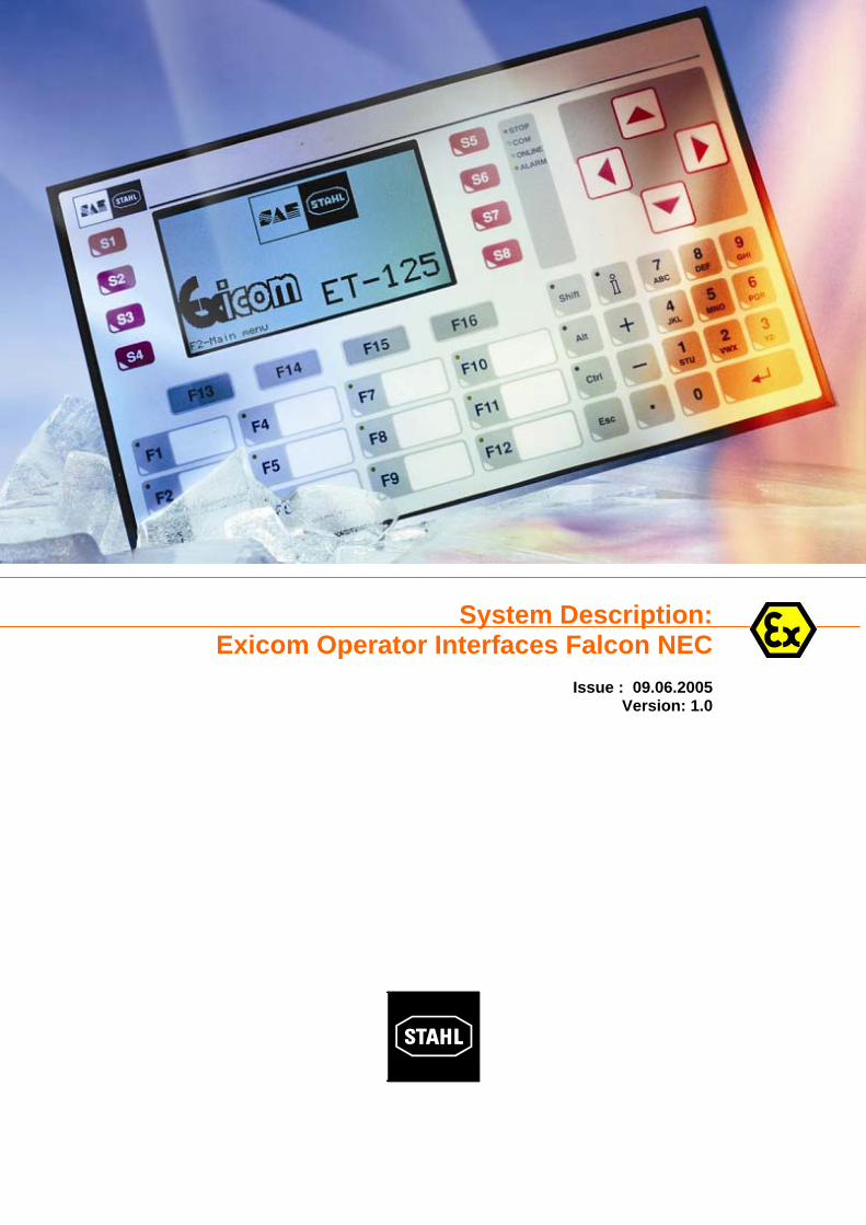
System Description: Exicom Operator Interfaces Falcon NEC
Issue : 09.06.2005
Version: 1.0

System Description Exicom Operator Interfaces Falcon NEC
Page 2 of 17 © R. STAHL HMI Systems GmbH/ SystemdescriptionExicomFalconNEC-1-1.doc/ 09.06.2005
Publisher and copyright holder: R. STAHL HMI SYSTEMS GMBH Im Gewerbegebiet Pesch 14 D-50767 Cologne http://www.sae-stahl.de E-mail:[email protected] Tel.: +49/(0)221/59808-200 Fax: +49/(0)221/59808-260 • All rights reserved. • This document may not be reproduced in whole or in part except with the written
consent of the publisher. • This document may be subject to technical changes. Although this manual has been produced with all due diligence, it may still contain errors, for which R. STAHL HMI Systems GmbH does not accept any liability. Cologne, dated 09.06.2005 Contact Information for North America R.Stahl Inc., 9001 Knight Road Houston TX 77054 Tel: 800-782-4357 Fax: 713-792-9301 E-Mail: [email protected] Web: rstahl.com Company background: Founded in 1998 under the name SAE-STAHL, R. STAHL HMI Systems GmbH today is a wholly owned subsidiary of the R. STAHL technology group and part of its explosion protection division. We specialise in the development and production of operating and monitoring systems both for standard industrial application and for use in hazardous areas. At present, STAHL HMI is the only company worldwide that offers the full range of both types of application. Our clients benefit from product lines with clearly outlined areas of application, separate device performance classes and a personal service. We operate on a global basis, and thus local representatives are available to customers worldwide to provide competent service and support.

Exicom Operator Interfaces Falcon NEC System Description
© R. STAHL HMI Systems GmbH/ SystemdescriptionExicomFalconNEC-1-1.doc/ 09.06.2005 page 3 of 17
System description
General information In all areas of industry, reliable operating and monitoring systems are becoming increasingly important. In the field of operator interfaces and visualization systems, R. STAHL HMI SYSTEMS GMBH in Cologne is the only supplier capable of offering the complete range of applications for both industrial and hazardous areas. Devices for use in hazardous areas are called “Exicom”, those for general purpose applications “ProVicom”. The product range contains:
• Operator Interfaces – integrated hardware and software products
• Open HMI – systems with open operating systems like Windows XP embedded
• Remote HMI – modern remote PC terminals
• Mobile HMI – portable devices Operator Interfaces Exicom Falcon With a wide variety of functions, these devices provide optimum visualization. Their active communication concept in combination with integrated functionality reduces the workload of the automation system.

System Description Exicom Operator Interfaces Falcon NEC
Page 4 of 17 © R. STAHL HMI Systems GmbH/ SystemdescriptionExicomFalconNEC-1-1.doc/ 09.06.2005
Exicom Falcon highlights Installation in hazardous areas worldwide International certificates for installation in hazardous areas are available, in particular ATEX (zone 1, 2 and 22) and NEC (class I, div.1 and div.2). Backlit displays Due to the ongoing development of display technology, STAHL HMI is able to offer displays with additional lighting features even for intrinsically safe devices.
• monochrome transflective LC displays • Wide display angles and font sizes of up to 1.2”, 30 mm • Optimum contrast due to black/white display • Perfect readability outside (transflective) as well as in unlit rooms (white LED
backlighting) • Increased temperature range • Font size of up to 1.2”, 30 mm for improved readability from great distances
Function key LEDs (ET-65 and ET-125) Increased temperature range Developed for installation in rough industrial environments, some with marine certification, increased temperature ranges and in combination with field housings made by R.STAHL, the operator interfaces can be installed almost anywhere.
• -4oF…+140oF (T4), –20°C...+60°C (T4) • -4oF…+158oF (T3), –20°C...+70°C (T3) • Field housings available with breather gland and heater (-22/40oF…, -30/40°C…)
Compatibility with older systems With regard to installation, software and functionality, the new systems are compatible with the old ET-4A, ET-9752 and ET-6 systems. Please note, however, the statutory requirements concerning new installations, replacements and repairs on the basis of NEC installations and ATEX 100a and ATEX 137 (installation). Engineering with SPSPlus WIN All Operator Interfaces use the SPSPlus WIN for the project design. This tool enables fast, efficient and cost-effective project design. Changing from one device to another is very simple. Connectivity with most automation systems A particular advantage of our systems is their seamless connectivity to most major automation systems. Generally, there is free access to all objects within an automation system with no limitation to arrays. For an up-to-date list of available systems, please refer to our homepage: www.STAHL-HMI.de New software features and enhancements
• Increased number of alarms from 240 to 512 with 32 alarms simultaneously active • Dynamic histogram protocol with up to 1,000 messages (previously 170) • 25 dynamic elements per page (variables, bar charts,…) (previously 15) • Improved input style (calculator style)
o Display of floating point (real) numerals important for control circuit images • Control of backlight via automation device • Indexing for optimum visualization of similar structures (reduces the number of process
images)

Exicom Operator Interfaces Falcon NEC System Description
© R. STAHL HMI Systems GmbH/ SystemdescriptionExicomFalconNEC-1-1.doc/ 09.06.2005 page 5 of 17
Products Exicom ET-65 Product details Intrinsically safe operator interface for installation in Zone 1, Zone 22 (ATEX), class 1, zone 1 and class 1 div. 1 (NEC). - TEXT performance class - Power supply via 9381/10 or 9143/10 - Serial data transfer via fieldbus isolator
9185/11-45-10 - Connections via screw terminals - Operating system software, engineering with SPSPlusWIN Technical details Display and keyboard
Display LCD monochrome transflective
Cover Transparent foil
Lighting LED backlight
with additional power supply 9381/10
Display size 5.3” x 1.6”, 134mm x 40.4mm
Resolution 240 x 64 pixels
Font size variable 0.2″-1.2″ 5-30 mm
Memory configuration Main memory 128 Kbyte Data memory 448 Kbyte
Keyboard Polyester membrane on
FR4 material > 1 million actions
Function keys 16 Alpha and system keys 23
Soft keys 4 Key / system LEDs 16 / 4
Interfaces Interfaces ET-65
Communication RS-422
Readers
Options: Barcode scanner, Wiegand reader, Proximity reader
Input: 8 binary inputs 3.3 V / 2 mA
Auxiliary power Nominal values
8 – 12.5 V 180 mA
Interfaces Signal isolator
Serial RS-232, RS-422/485
Fieldbus
Profibus with 9185/11-46-10
MPI with MPI-Box SSW7-RK512-RS-232
Ethernet TCP/IP, UDP with SK-Cobox
Ambient conditions
Ambient temperature
Operation: -4oF - +158oF (140oF at T4)-20°C - +70°C(+60° at T4)
Storage -22oF - +176oF -30°C - +80°C
Humidity 90% at 104oF, 40°C, without condensation
Vibration 10...55Hz (1 min.): 1.5 mm, XYZ (per 2 h)
Shock 50 G, 11 ms
Dimensions
Front (W x H) 11.5” x 5.75” 290 x 146mm2
Cut-out (W x H x D)
10.83″ x 5.16″ x 2.95″ 275 x 131 x 75mm3
Explosion protection
ATEX With power supply 9143/10
e II 2G EEx ia IIC T4, Ta = -20°C ... +60 oC ex II 2G EEx ia IIC T3,
Ta = -20°C ... +70 oC ex II 3 D IP65 T125°C
FM With power supply 9381/10
Class I, Zone 1, AEx ia IIC T4 Class I, II, III, Division 1, Groups
ABCDEFG; T4
System Description Exicom Operator Interfaces Falcon NEC
Page 6 of 17 © SAE-STAHL GMBH SystemdescriptionExicomFalconNEC-1-1.doc/ 09.06.2005
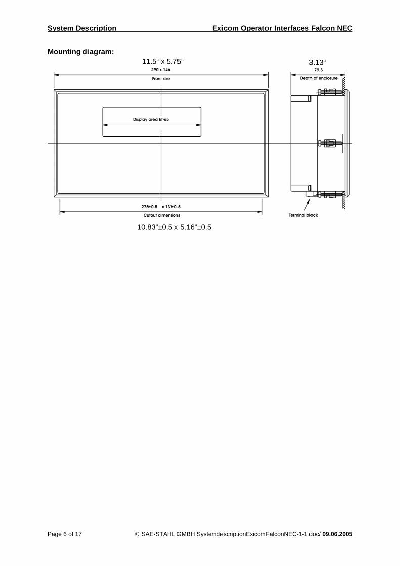
Mounting diagram:
11.5“ x 5.75“ 3.13“
10.83“±0.5 x 5.16“±0.5

Exicom Operator Interfaces Falcon NEC System Description
© SAE-STAHL GMBH SystemdescriptionExicomFalconNEC-1-1.doc/ 09.06.2005 Page 7 of 17
Exicom ET-75 Product details Intrinsically safe operator interface for installation in Zone 1, Zone 22 (ATEX), class 1, zone 1 and class 1 div. 1 (NEC). - GRAPHIC performance class - Power supply via 9381/10 or 9143/10 - Serial data transfer via fieldbus isolator
9185/11-45-10 - Connections via screw terminals - Operating system software, engineering with SPSPlusWIN - System compatibility with Exicom ET-9752 Technical details Display and keyboard
Display LCD monochrome transflective
Cover Transparent foil
Lighting LED backlight
with additional power supply 9381/10
Display size 4.5” x 2.5”, 114mm x 64mm
Resolution 240 x 128 pixels
Font size variable 0.2″-1.2″, 5-30 mm
Memory configuration Main memory 128 Kbyte Data memory 448 Kbyte
Keyboard Polyester membrane on
FR4 material > 1 million actions
Function keys 8 Alpha and system keys 23
Soft keys -
Key / system LEDs - / 4 + 4
Interfaces Interfaces ET-75
Communication RS-422
Readers
Options: Barcode scanner, Wiegand reader, Proximity reader
Input: 8 binary inputs 3.3 V / 2 mA
Auxiliary power Nominal values
8 – 12.5 V 180 mA
Interfaces Signal isolator
Serial RS-232, RS-422/485
Fieldbus
Profibus with 9185/11-46-10
MPI with MPI-Box SSW7-RK512-RS-232
Ethernet TCP/IP, UDP with SK-Cobox
Ambient conditions
Ambient temperature
Operation: -4oF - +158oF (140oF at T4) -20°C - +70°C (+60° for T4)
Storage -22oF - +176oF -30°C - +80°C
Humidity 90% at 104oF, 40°C, without condensation
Vibration 10...55Hz (1 min.): 1.5 mm, XYZ (per 2 h)
Shock 50 G, 11 ms
Dimensions
Front (W x H) 11.5” x 5.75” 290 x 146mm2
Cut-out (W x H x D)
10.83″ x 5.16″ x 2.95″ 275 x 131 x 75mm3
Explosion protection
ATEX With power supply 9143/10
e II 2G EEx ia IIC T4, Ta = -20°C ... +60 oC ex II 2G EEx ia IIC T3,
Ta = -20°C ... +70 oC ex II 3 D IP65 T125°C
FM With power supply 9381/10
Class I, Zone 1, AEx ia IIC T4Class I, II, III, Division 1, Groups ABCDEFG; T4

System Description Exicom Operator Interfaces Falcon NEC
Page 8 of 17 © SAE-STAHL GMBH SystemdescriptionExicomFalconNEC-1-1.doc/ 09.06.2005
Mounting diagram:
11.5“ x 5.75“ 3.13“
10.83“±0.5 x 5.16“±0.5
Exicom Operator Interfaces Falcon NEC System Description
© SAE-STAHL GMBH SystemdescriptionExicomFalconNEC-1-1.doc/ 09.06.2005 Page 9 of 17
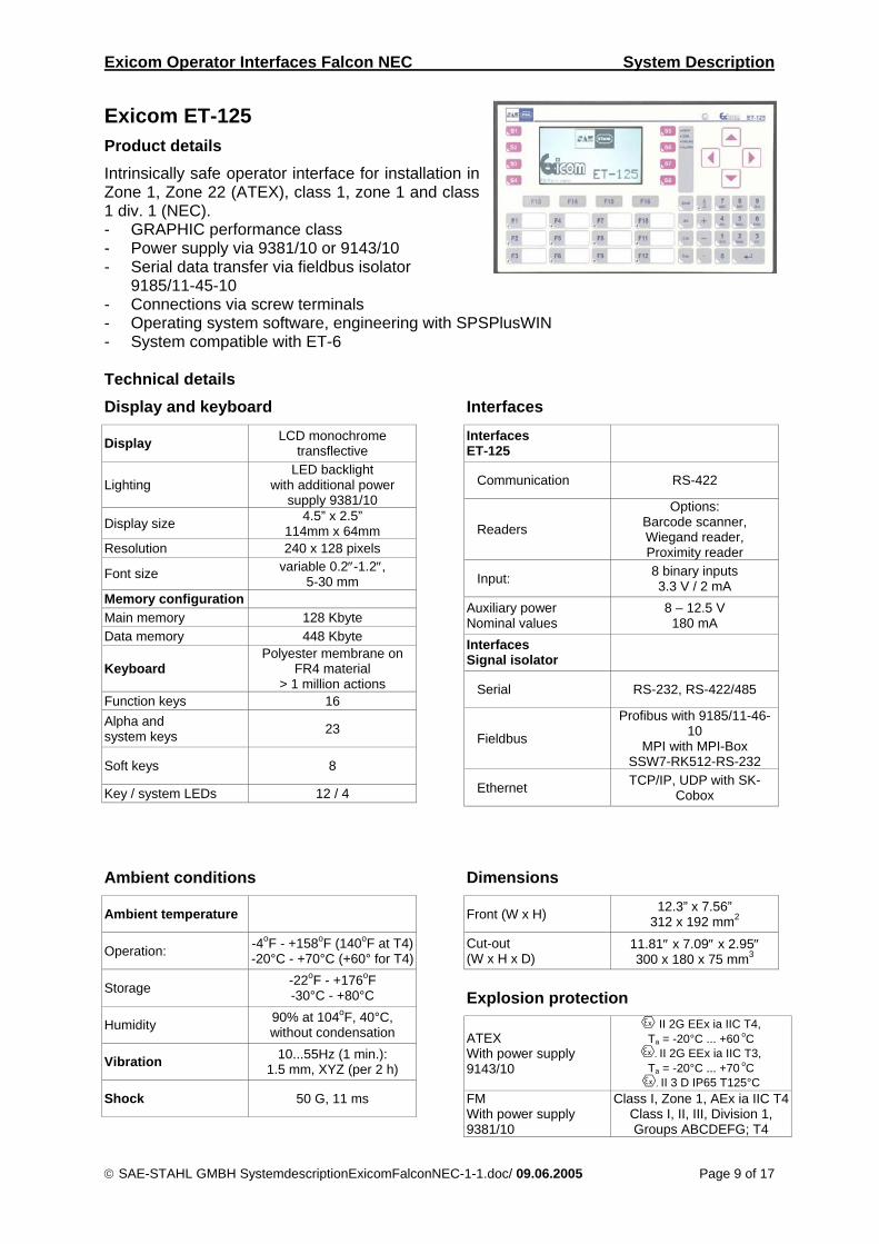
Exicom ET-125 Product details Intrinsically safe operator interface for installation in Zone 1, Zone 22 (ATEX), class 1, zone 1 and class 1 div. 1 (NEC). - GRAPHIC performance class - Power supply via 9381/10 or 9143/10 - Serial data transfer via fieldbus isolator
9185/11-45-10 - Connections via screw terminals - Operating system software, engineering with SPSPlusWIN - System compatible with ET-6 Technical details Display and keyboard
Display LCD monochrome transflective
Lighting LED backlight
with additional power supply 9381/10
Display size 4.5” x 2.5” 114mm x 64mm
Resolution 240 x 128 pixels
Font size variable 0.2″-1.2″, 5-30 mm
Memory configuration Main memory 128 Kbyte Data memory 448 Kbyte
Keyboard Polyester membrane on
FR4 material > 1 million actions
Function keys 16 Alpha and system keys 23
Soft keys 8
Key / system LEDs 12 / 4
Interfaces Interfaces ET-125
Communication RS-422
Readers
Options: Barcode scanner, Wiegand reader, Proximity reader
Input: 8 binary inputs 3.3 V / 2 mA
Auxiliary power Nominal values
8 – 12.5 V 180 mA
Interfaces Signal isolator
Serial RS-232, RS-422/485
Fieldbus
Profibus with 9185/11-46-10
MPI with MPI-Box SSW7-RK512-RS-232
Ethernet TCP/IP, UDP with SK-Cobox
Ambient conditions
Ambient temperature
Operation: -4oF - +158oF (140oF at T4) -20°C - +70°C (+60° for T4)
Storage -22oF - +176oF -30°C - +80°C
Humidity 90% at 104oF, 40°C, without condensation
Vibration 10...55Hz (1 min.): 1.5 mm, XYZ (per 2 h)
Shock 50 G, 11 ms
Dimensions
Front (W x H) 12.3” x 7.56” 312 x 192 mm2
Cut-out (W x H x D)
11.81″ x 7.09″ x 2.95″ 300 x 180 x 75 mm3
Explosion protection
ATEX With power supply 9143/10
e II 2G EEx ia IIC T4, Ta = -20°C ... +60 oC ex II 2G EEx ia IIC T3,
Ta = -20°C ... +70 oC ex II 3 D IP65 T125°C
FM With power supply 9381/10
Class I, Zone 1, AEx ia IIC T4Class I, II, III, Division 1, Groups ABCDEFG; T4

System Description Exicom Operator Interfaces Falcon NEC
Page 10 of 17 © SAE-STAHL GMBH SystemdescriptionExicomFalconNEC-1-1.doc/ 09.06.2005
Mounting diagram: 12.3“ x 7.56“ 3.13“
11.81“±0.5 x 7.09“±0.5
Exicom Operator Interfaces Falcon NEC System Description
© SAE-STAHL GMBH SystemdescriptionExicomFalconNEC-1-1.doc/ 09.06.2005 Page 11 of 17
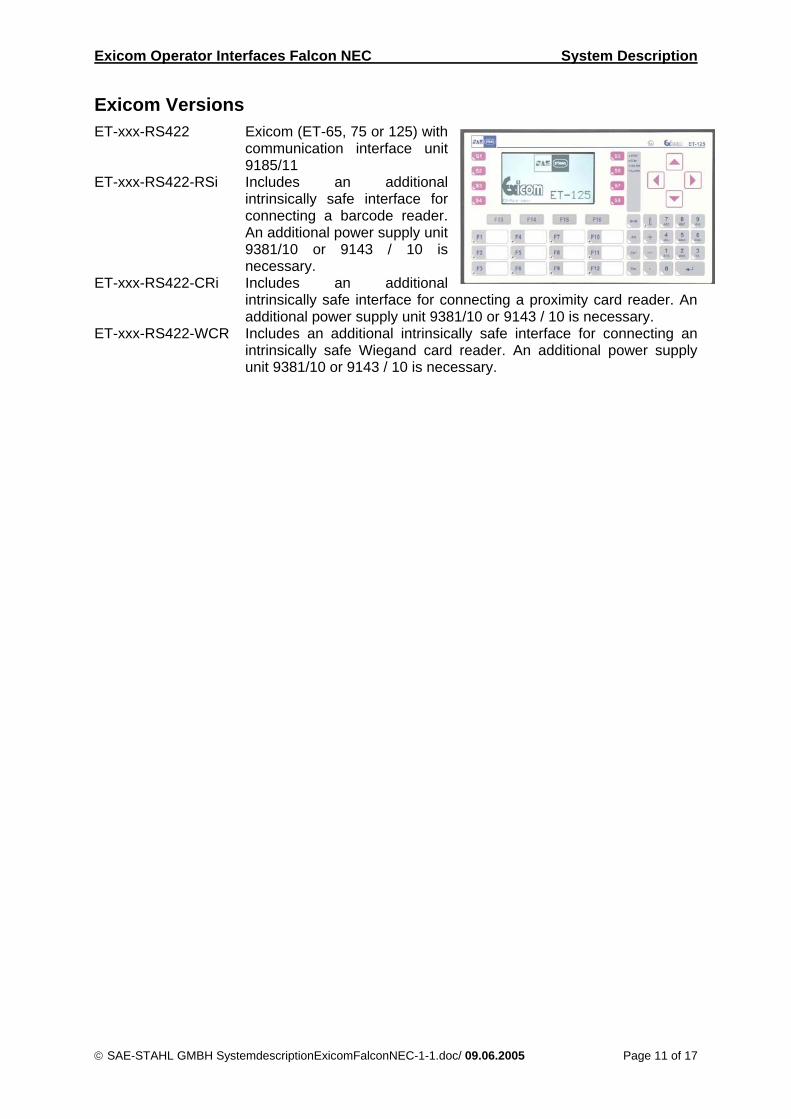
Exicom Versions ET-xxx-RS422 Exicom (ET-65, 75 or 125) with
communication interface unit 9185/11
ET-xxx-RS422-RSi Includes an additional intrinsically safe interface for connecting a barcode reader. An additional power supply unit 9381/10 or 9143 / 10 is necessary.
ET-xxx-RS422-CRi Includes an additional intrinsically safe interface for connecting a proximity card reader. An additional power supply unit 9381/10 or 9143 / 10 is necessary.
ET-xxx-RS422-WCR Includes an additional intrinsically safe interface for connecting an intrinsically safe Wiegand card reader. An additional power supply unit 9381/10 or 9143 / 10 is necessary.

System Description Exicom Operator Interfaces Falcon NEC
Page 12 of 17 © SAE-STAHL GMBH SystemdescriptionExicomFalconNEC-1-1.doc/ 09.06.2005
Accessories 9185/11-45-10, Fieldbus Isolator
Signal isolator for the intrinsically safe operator terminals ET-65, ET-75 and ET-125 - Intrinsically safe serial connection to the operator terminal - Connections via Sub-D - System compatibility with the Exicom ET-9752 and ET-6 as a
replacement for the 9373/21. In combination with the 9381/10 power supply it can also replace the ET-SV/3.
Power supply 9381/10-120-200 (NEC Installations) Power supply for the operation of the intrinsically safe ET-65, ET-75 and ET-125 operator terminals, the backlight and the readers. - 9381/10-120-200-10 24V DC - 9381/10-120-200-50 10-230 V AC - Connections via screw terminals - System compatibility with Exicom ET-9752, and ET-6. In combination with the 9185/11-
45-10 signal isolator it can also replace the ET-SV/3. This power supply unit is not available for use in an installation according to ATEX. Power supply 9143/10- (ATEX Installations)
Power supply for the operation of the intrinsically safe ET-65, ET-75 and ET-125 operator terminals, the backlight and the readers. Operator terminals and backlight: - 9143/10-114-200-10 24V DC - 9143/10-114-200-20 10-230 V AC Readers: - 9143/10-104-220-10 24V DC - 9143/10-104-220-20 10-230 V AC
- Connections via screw terminals - System compatiblewith the Exicom ET-9752 and ET-6. In combination with the 9185/11-
45-10 signal isolator it can also replace the ET-SV/3. This power supply unit is not available for use in an installation according to NEC.
Exicom Operator Interfaces Falcon NEC System Description
© SAE-STAHL GMBH SystemdescriptionExicomFalconNEC-1-1.doc/ 09.06.2005 Page 13 of 17
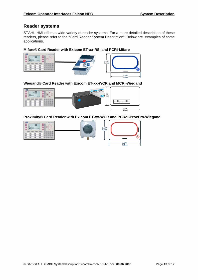
Reader systems STAHL-HMI offers a wide variety of reader systems. For a more detailed description of these readers, please refer to the “Card Reader System Description”. Below are examples of some applications. Mifare® Card Reader with Exicom ET-xx-RSi and PCRi-Mifare Wiegand® Card Reader with Exicom ET-xx-WCR and MCRi-Wiegand Proximity® Card Reader with Exicom ET-xx-WCR and PCRdi-ProxPro-Wiegand
System Description Exicom Operator Interfaces Falcon NEC
Page 14 of 17 © SAE-STAHL GMBH SystemdescriptionExicomFalconNEC-1-1.doc/ 09.06.2005
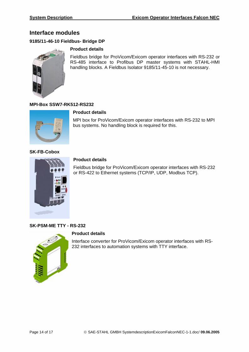
Interface modules 9185/11-46-10 Fieldbus- Bridge DP
Product details Fieldbus bridge for ProVicom/Exicom operator interfaces with RS-232 or RS-485 interface to Profibus DP master systems with STAHL-HMI handling blocks. A Fieldbus Isolator 9185/11-45-10 is not necessary.
MPI-Box SSW7-RK512-RS232 Product details MPI box for ProVicom/Exicom operator interfaces with RS-232 to MPI bus systems. No handling block is required for this.
SK-FB-Cobox Product details Fieldbus bridge for ProVicom/Exicom operator interfaces with RS-232 or RS-422 to Ethernet systems (TCP/IP, UDP, Modbus TCP).
SK-PSM-ME TTY - RS-232 Product details Interface converter for ProVicom/Exicom operator interfaces with RS-232 interfaces to automation systems with TTY interface.
Exicom Operator Interfaces Falcon NEC System Description
© SAE-STAHL GMBH SystemdescriptionExicomFalconNEC-1-1.doc/ 09.06.2005 Page 15 of 17
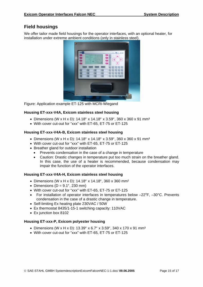
Field housings We offer tailor made field housings for the operator interfaces, with an optional heater, for installation under extreme ambient conditions (only in stainless steel).
Figure: Application example ET-125 with MCRi-Wiegand Housing ET-xxx-V4A, Exicom stainless steel housing
• Dimensions (W x H x D): 14.18″ x 14.18″ x 3.59″, 360 x 360 x 91 mm³ • With cover cut-out for “xxx” with ET-65, ET-75 or ET-125
Housing ET-xxx-V4A-B, Exicom stainless steel housing
• Dimensions (W x H x D): 14.18″ x 14.18″ x 3.59″, 360 x 360 x 91 mm³ • With cover cut-out for “xxx” with ET-65, ET-75 or ET-125 • Breather gland for outdoor installation
• Prevents condensation in the case of a change in temperature • Caution: Drastic changes in temperature put too much strain on the breather gland.
In this case, the use of a heater is recommended, because condensation may impair the function of the operator interfaces.
Housing ET-xxx-V4A-H, Exicom stainless steel housing
• Dimensions (W x H x D): 14.18″ x 14.18″, 360 x 360 mm² • Dimensions (D = 9.1″, 230 mm) • With cover cut-out for “xxx” with ET-65, ET-75 or ET-125 • For installation of operator interfaces in temperatures below –22oF, –30°C. Prevents
condensation in the case of a drastic change in temperature. • Self-limiting Ex heating plate 230VAC / 50W • Ex thermostat 8435/1-15-1 switching capacity: 110VAC • Ex junction box 8102
Housing ET-xxx-P, Exicom polyester housing
• Dimensions (W x H x D): 13.39″ x 6.7″ x 3.59″, 340 x 170 x 91 mm³ • With cover cut-out for “xxx” with ET-65, ET-75 or ET-125

System Description Exicom Operator Interfaces Falcon NEC
Page 16 of 17 © SAE-STAHL GMBH SystemdescriptionExicomFalconNEC-1-1.doc/ 09.06.2005
Systems / couplings Exicom general power supply diagram Hazardous area Safe area 24V/110-230V 1
2*
3*
1. Power supply 9381/10-120-200 2. optional 9381/10-120-200 power supply for backlight 3. optional 9381/10-120-200 power supply for readers (scanner, Wiegand effect reader,
etc.) for device with appropriate interface (optional) 1 and 2. For ATEX installations use the 9143/10-114-200 3. For ATEX installations use the 9143/10-104-220
General signal route diagram (coupling) Hazardous area Safe area RS-232 or RS-485/422
RS-422
Up to 8 operator interfaces dependant on the protocol driver and its interface features
Optional interface module: MPI-Bus MPI-Box SSW7-RK512-RS-232 Ethernet SK- Cobox DR1/IAP* Profibus 9185/11-46-10 Fieldbus Bridge DP* TTY SK-PSM-ME TTY-RS-232 * replaces 9185/11-45-10 and supports only one device in the Ex area

Exicom Operator Interfaces Falcon NEC System Description
© SAE-STAHL GMBH SystemdescriptionExicomFalconNEC-1-1.doc/ 09.06.2005 Page 17 of 17
Software Design
Physical connection z.B. TTY
Communication protocol z.B. 3964R/RK512
Data area (e.g. DB /DW)
Application
SPS
9185
Physical connection RS 422
Communication protocol z.B. 3964R/RK512
Data area
Application buffer 480 KByte Flash EPROM
Pages, Fonts
ExicomDisplay
Keys
Protocol buffer
Control LED´s
Display • Graphic displays capable of displaying 3 different sized fonts simultaneously. • Display of bitmaps (not for ET-65 and MT-65) Communication • Transparent active check by the terminal via the control protocol. Communication
programming is therefore no longer required. • Implementation of several protocols within one operator interface (can be switched in
the system configuration). Advancing, Moving, Positioning Function and cursor keys are transferred directly and quickly to the PLC or DCS. Displaying, parameter setting, dosing, regulating • Simple and convenient generation of display and parameter setting menus • 25 optional process variables, in suitable format, per process diagram
♦ numerical data formats with limits and scaling ♦ bar chart and pointer chart with direct link to process variables (GRAPHIC only) ♦ Bi-directional bar chart with dynamic operating point (GRAPHIC only) ♦ all scaleable values from the automation system
• The read out and data conversion is done automatically in the terminal • Direct input via barcode (scanner) Monitoring and Checking Fault processing per individual bit with representation as new value, first value or priority. Recording functions. Menu Structures • Simple generation of menu structures (parameter setting masks, tree structures)
without PLC program. • Direct activation of internal functions via function key. Programming • Generation of process diagrams, fault texts etc. by means of PC program for Windows
95/98/NT/2000/XP • Generation or changing of fonts. Various national alphabets are possible (e.g. Cyrillic,
Greek, Japanese...). • Import of pixel graphics in bitmap format.