System Clock Manual Version 2 - ABB Ltd · INSUM® MCU Parameter Description Software revision 2.1...
22
ABB Protect IT – MNS Motor Management INSUM System Clock Manual Version 2.3
-
Upload
truonghuong -
Category
Documents
-
view
219 -
download
1
Transcript of System Clock Manual Version 2 - ABB Ltd · INSUM® MCU Parameter Description Software revision 2.1...

ABB
ProtectIT – MNS Motor Management INSUM
System Clock Manual Version 2.3


INSUM®
MCU Parameter Description
Software revision 2.1
1 1TGC 901080 M0202 Edition July 2003
INSUM® System Clock Manual
Version 2.3

INSUM®
MCU Parameter Description Software Version 2.1
2 1TGC 901080 M0202 Edition July 2003
NOTICE The information in this document is subject to change without notice and should not be construed as a commitment by ABB Schaltanlagentechnik GmbH. ABB Schaltanlagentechnik GmbH assumes no responsibility for any errors that may appear in this document. In no event shall ABB Schaltanlagentechnik GmbH be liable for direct, indirect, special, incidental, or consequential damages of any nature or kind arising from the use of this document, nor shall ABB Schaltanlagentechnik GmbH be liable for incidental or consequential damages arising from use of any software or hardware described in this document. This document and parts thereof must not be reproduced or copied without ABB Schaltanlagentechnik GmbH’s written permission, and the contents thereof must not be imparted to a third party nor be used for any unauthorized purpose. Permission to translate the document shall be obtained from ABB Schaltanlagentechnik GmbH. The translated document shall be sent to ABB Schaltanlagentechnik GmbH together with the confirmation that the content of the document is the same. The software described in this document is furnished under a license and may be used, copied, or disclosed only in accordance with the terms of such license. TRADEMARKS MNS and INSUM are registered trademarks of ABB Schaltanlagentechnik GmbH Microsoft, Windows and Windows NT are registered trademarks of Microsoft Corporation. Echelon, LON, LONWORKS, LonTalk, Neuron are trademarks of Echelon Corporation registered in U.S. and other countries. Reference document Ref.No.: 1TGB 350019 R1.1

INSUM® System Clock Manual
Version 2.3
ABB 3 1TGC 901080 M0202 Edition July 2003
1 General Information ...........................................................................................................4
1.1 Introduction ................................................................................................................4 1.2 Objective ....................................................................................................................4 1.3 Related Documents ...................................................................................................4
2 Operation ............................................................................................................................5 2.1 General ......................................................................................................................5 2.2 Slave Mode ................................................................................................................5 2.3 Master Mode ..............................................................................................................5
3 Hardware Installation .........................................................................................................6 3.1 Hardware Characteristics...........................................................................................6 3.2 Indications and Pushbuttons......................................................................................6 3.3 Self Installation on the LON network..........................................................................6 3.4 Hardware installation using Hopf GPS System .........................................................7
3.4.1 Structure........................................................................................................7 3.4.2 Description ....................................................................................................7
3.5 Hardware installation without GPS System ...............................................................8 3.5.1 Structure........................................................................................................8 3.5.2 Description ....................................................................................................8
4 Configuration......................................................................................................................9 4.1 Application using Hopf GPS System..........................................................................9
4.1.1 Configuration of Hopf GPS System...............................................................9 4.1.2 Configuration of System Clock in Slave mode ..............................................9
4.2 Application without GPS System ...............................................................................9 4.2.1 Configuration of System Clock in Master mode ............................................9 4.2.2 Configuration of System Clock in Slave mode ............................................10
5 Accuracy of time and time stamp within INSUM...........................................................11 5.1 Time accuracy in the INSUM system.......................................................................11
5.1.1 MCU internal ...............................................................................................11 5.1.2 Between MCUs ...........................................................................................11 5.1.3 Transmission and internal delay (System Clock) ........................................11 5.1.4 Conclusion...................................................................................................11
5.2 Slave mode ..............................................................................................................11 5.3 Master mode ............................................................................................................11
6 Alarm and Maintenance functions..................................................................................12 6.1 Lifesign signal ..........................................................................................................12 6.2 Running on RTC / GPS...........................................................................................12 6.3 ‘No connection’ detection.........................................................................................12 6.4 No valid time detection.............................................................................................12 6.5 Detection Master/ Slave mode.................................................................................12
7 Parameter Configuration of Hopf GPS System .............................................................13 7.1 Configuration of serial parameter interface 1...........................................................13 7.2 Configuration of serial parameter interface 2...........................................................13 7.3 Configuration of mode of reception (GPS reception quality) ...................................13 7.4 Configuration of optical coupler 1 ............................................................................13 7.5 Configuration of optical coupler 2 ............................................................................13 7.6 Configuration of optical coupler 3 ............................................................................13
8 Annex A:Technical Data ..................................................................................................14 8.1 Mechanical Data ......................................................................................................14 8.2 General Electrical Characteristics............................................................................14 8.3 Electromagnetic Compatibility..................................................................................14 8.4 Insulation test...........................................................................................................15 8.5 Environmental Testing .............................................................................................15
9 Annex B - INSUM Terms and Abbreviations..................................................................16 Index ........................................................................................................................................19

INSUM® System Clock Manual
4 ABB 1TGC 901080 M0202 Edition July 2003
Notes: 1 General Information 1.1 Introduction The task of the System Clock is to guarantee that the system time is the same at all connected INSUM devices (system time). It sends cyclically a time information via the INSUM internal LON network to the connected field devices (MCU, ITS, PR112) on the same ICU. This enables the field devices to provide time stamped messages. The System Clock works with the MCU devices version 2.1 onwards. Support of clock setting functions via MMI is provided with INSUM Release 2.3. A software update of MMI, Gateways and INSUM OS to Release 2.3 is recommended if the System Clock is used. 1.2 Objective This Manual describes the INSUM System Clock device functions, handling and functions. Further on it provides detailed information on the implementation of the System Clock into the INSUM System. 1.3 Related Documents ABB INSUM Documentation: 1TGC 901007 B0201 INSUM Technical Information 1TGC 901021 M0201 INSUM MCU Users Guide 1TGC 901026 M0201 INSUM MCU Parameter Description 1TGC 901034 M0201 INSUM MMI Operating Instruction 1TGC 901030 M0201 INSUM MMI Quick Guide 1TGC 901042 M0201 INSUM Modbus Gateway Manual 1TGC 901052 M0201 INSUM Profibus Gateway Manual 1TGC 901060 M0201 INSUM Ethernet Gateway Manual 1TGC 901090 M0201 INSUM Control Access Guide 1TGC 901091 M0201 INSUM Failsafe Guide 1TGC 901092 M0201 INSUM Dual Redundancy Guide 1TGC 901093 M0201 INSUM Network Management Guide SACE RH 0080 Rev.l PR112/ PD-L LON Works Interface V2.0 1SEP 407948 P0001 Users Manual Intelligent Tier Switch (ITS) Technical Documentation Hopf GmbH Germany: Technical Description - GPS Satellite Radio Controlled Clock 6870 System Information GPS

INSUM® System Clock Manual
5 ABB 1TGC 901080 M0202 Edition July 2003
Notes: 2 Operation 2.1 General The System Clock module can operate in two different modes depending on the kind of receiving/sending the time information. The respective modes are called Slave and Master and can be set via MMI (from software version 2.3 onwards). The type of mode depends on the installation of the hardware and its function. For Installation of Hardware see chapter 3. 2.2 Slave Mode If the System Clock is configured as a Slave it gets the time information from a serial interface. In that mode an additional hardware is required, which provides the needed time information. On one hand, the Hopf GPS System 6870 can be used to ensures a very accurate time. The time
base is synchronized by a global installed satellite system (GPS). On the other hand, for lower requirements on absolute accuracy, one System Clock in the switchgear
can run in Master mode. The received time is changed into a domain wide broadcast LON NV and published to all connected subnets of one ICU backplane.
2.3 Master Mode If the System Clock is configured as a Master the device itself generates time information by using an internal RTC with lower accuracy. This information is published as NV and provided via RS422 additionally.

INSUM® System Clock Manual
6 ABB 1TGC 901080 M0202 Edition July 2003
Notes: 3 Hardware Installation 3.1 Hardware Characteristics The mechanical setup of the System Clock is like any other ICU component, mounted on the backplane, plug-in type. The device has to be connected to one extension plate and draws power from the backplane.
Figure1: System Clock Module Front Plate 3.2 Indications and Pushbuttons System Clock Indications
Power: A green LED indicates that the 24VDC-power supply for the module is available
Receive error: A steady shining yellow LED indicates an error depending on System Clock mode
Sync. pulse: A flashing yellow LED indicates that the System Clock is sending time updates
GPS active: A steady shining yellow LED indicates that the module is receiving a valid GPS time information from GPS device (only in Slave mode available)
Service/Stat: A yellow LED indicates the Service/Status of the NEURON (LON Communication Chip)
System Clock Pushbuttons
GPS config.: Configures the connected Hopf GPS System 6870 (only in Slave mode available)
Service/Req: The service button will cause the System Clock to broadcast a service pin message on the network
3.3 Self Installation on the LON network As soon as the connection to the backplane is made the System Clock gets the subnet/ node address 05/05 by self installation. Do not change it if not necessary. If the device is started for the first time, it is running in Slave mode. After power up the clock starts with the last chosen mode.
Power Receive errorGPS active
INSUM Clock
Service/Stat.
GPS config.
Service/Req. Sync. pulse
INSUM® System Clock Manual
7 ABB 1TGC 901080 M0202 Edition July 2003
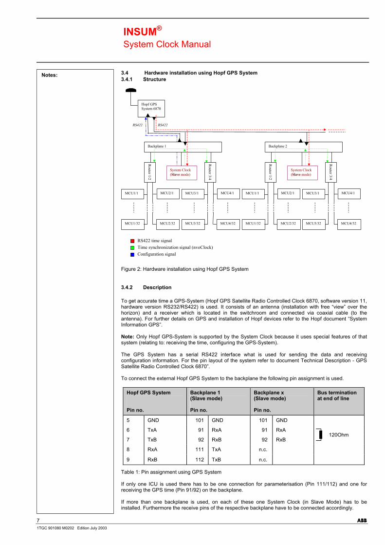
Notes: 3.4 Hardware installation using Hopf GPS System 3.4.1 Structure
RS422RS422
Hopf GPSSystem 6870
System Clock(Slave mode)
Router 1/2
MCU1/1
MCU1/32
MCU2/1
MCU2/32
Router 3/4
MCU3/1
MCU3/32
MCU4/1
MCU4/32
System Clock(Slave mode)
Router 1/2
MCU1/1
MCU1/32
MCU2/1
MCU2/32
Router 3/4
MCU3/1
MCU3/32
MCU4/1
MCU4/32
Backplane 2Backplane 1
RS422 time signalTime synchronization signal (nvoClock)Configuration signal
Figure 2: Hardware installation using Hopf GPS System 3.4.2 Description
To get accurate time a GPS-System (Hopf GPS Satellite Radio Controlled Clock 6870, software version 11, hardware version RS232/RS422) is used. It consists of an antenna (installation with free “view” over the horizon) and a receiver which is located in the switchroom and connected via coaxial cable (to the antenna). For further details on GPS and installation of Hopf devices refer to the Hopf document “System Information GPS”. Note: Only Hopf GPS-System is supported by the System Clock because it uses special features of that system (relating to: receiving the time, configuring the GPS-System). The GPS System has a serial RS422 interface what is used for sending the data and receiving configuration information. For the pin layout of the system refer to document Technical Description - GPS Satellite Radio Controlled Clock 6870”. To connect the external Hopf GPS System to the backplane the following pin assignment is used.
Hopf GPS System Pin no.
Backplane 1 (Slave mode) Pin no.
Backplane x (Slave mode) Pin no.
Bus termination at end of line
5 GND 101 GND 101 GND
6 TxA 91 RxA 91 RxA
7 TxB 92 RxB 92 RxB 120Ohm
8 RxA 111 TxA n.c.
9 RxB 112 TxB n.c.
Table 1: Pin assignment using GPS System If only one ICU is used there has to be one connection for parameterisation (Pin 111/112) and one for receiving the GPS time (Pin 91/92) on the backplane. If more than one backplane is used, on each of these one System Clock (in Slave Mode) has to be installed. Furthermore the receive pins of the respective backplane have to be connected accordingly.

INSUM® System Clock Manual
8 ABB 1TGC 901080 M0202 Edition July 2003
Notes: Note: Only one System Clock must have a connection to parameterise the GPS System. It is recommended to use the module near the GPS receiver module. The maximum number of System Clock modules is 32 whereby the last one has to get a bus termination for RS422. The RS422 lines have to have a maximum length of 500m whereas the sum of all stub lengths is max. 6.60m. 3.5 Hardware installation without GPS System 3.5.1 Structure
RS422
System Clock (Master mode)
Router 1/2
MCU1/1
MCU1/32
MCU2/1
MCU2/32
Router 3/4
MCU3/1
MCU3/32
MCU4/1
MCU4/32
System Clock (Slave mode)
Router 1/2
MCU1/1
MCU1/32
MCU2/1
MCU2/32
Router 3/4
MCU3/1
MCU3/32
MCU4/1
MCU4/32
Backplane 2 Backplane 1
Time synchronization signal (nvoClock)RS422 time signal
Figure 3: Hardware installation without GPS System 3.5.2 Description If the requirement to the absolute accuracy is low the internal RTC of the System Clock can be used to provide the system with the time information. In that case one System Clock has to run in Master mode. If only one ICU is in use, no additional wiring is necessary for that backplane. If more than one backplane is used, the System Clock offers the possibility to distribute the generated time information via RS422 to enable other System Clocks (in Slave mode) to process the sent time. In that case, on each of these backplanes a System Clock (in Slave mode) has to be installed. Furthermore the transmit pins (111/112) of the backplane containing the sending System Clock have to be connected to the receive pins (91/92) of the respective backplanes. The following table shows the corresponding pin assignment.
Backplane 1 (Master mode)
Pin no.
Backplane 2 (Slave mode)
Pin no.
Backplane x (Slave mode)
Pin no.
Bus termination at end of line
101 GND 101 GND 101 GND
91 n.c. n.c. n.c n.c. n.c.
92 n.c. n.c. n.c. n.c. n.c.
111 TxA 91 RxA 91 RxA
112 TxB 92 RxB 92 RxB
120Ohm
Table 2: Pin assignment without a GPS System Note: The maximum number of modules is 32 whereby the last one has to get a bus termination for RS422. The RS422 line maximum length is 500m whereas the summation of all stub lengths is max. 6.60m.

INSUM® System Clock Manual
9 ABB 1TGC 901080 M0202 Edition July 2003
Notes: 4 Configuration After the hardware installation the System Clock has to be configured depending on the particular application. 4.1 Application using Hopf GPS System 4.1.1 Configuration of Hopf GPS System Hopf GPS System and System Clock communicate to each other by using a serial connection (RS422). To allow a working connection both devices have to have the same transfer parameters (transfer rate, number of data bits, number of stop bits, kind of parity). To set the Hopf GPS System to default settings, different steps have to be done. 1. Connect the Hopf GPS System to the power supply and to the backplane 2. Press the Def button on the GPS System until the CLK-LED is off 3. The default parameters are: baudrate: 9600; data bit: 8; stop bit: 1; parity: no
After this initialization a serial communication between GPS System and the System Clock is possible. All other settings are done by System Clock (refer next paragraph). 4.1.2 Configuration of System Clock in Slave mode If the System Clock is running as Slave, it can receive time signal via RS422 and supply the connected devices with the generated output NV (nvoClock). If a System Clock is used the first time, the default setting is Slave mode. No configuration is required. The following steps are necessary to change the mode: 1. Connect the System Clock to the backplane 2. Change the System Clock mode to Slave using the MMI: Select System Configuration and enter Select Mode, change it to Slave and enter Press function key Send Escape the System Clock menu
Pressing the 'GPS config' button on the front panel of the device for approximately 3 sec (all three LED’s switch ON and OFF) configures the Hopf GPS System (exclusive the communication parameter). For more detail refer to the Appendix of this document. Attention: To use the configuration feature the output of System Clock has to be connected in an appropriate manner (refer to chapter Hardware installation). Note: If more than one System Clock is used, all devices have to run in Slave mode and can be installed on every backplane subject to the condition that all backplanes are linked together accordingly (refer to chapter Hardware installation). 4.2 Application without GPS System 4.2.1 Configuration of System Clock in Master mode If the System Clock is running in Master mode, it generates the time signal by using an internal RTC. The created NV nvoClock is send to all connected devices and additional the time information is supplied via RS422 to enable other System Clocks (in Slave mode) to handle it. The following steps are necessary to change the mode: 1. Connect the System Clock to the backplane 2. Change the System Clock mode to Master using the MMI Select System Configuration and enter Select Mode, change it to Master and enter Press function key Send Escape the System Clock menu

INSUM® System Clock Manual
10 ABB 1TGC 901080 M0202 Edition July 2003
Notes: Now the System Clock is configured as Master. If the time sent by the module is not correct or the Receive Error LED is shining (indicates an invalid RTC time) set new time and date with the following steps: 3. Set new date and time using the MMI Select System Configuration and enter Select Date/Time and enter Change the value via encoder wheel and the position with and function keys Press function key Send Escape the System Clock menu
Attention: To ensure a error free running of System Clock and all connected devices use always UTC for system time. Note: If more than one System Clock is used, all additional devices has to run in Slave mode (see above) and can be installed on each backplane provided that all backplanes are linked together (refer to chapter Hardware installation). 4.2.2 Configuration of System Clock in Slave mode If the System Clock is running as Slave, it can receive time signal via RS422 and supply the connected devices with the generated output NV (nvoClock). If a System Clock is used the first time, the default setting is Slave mode. No configuration is required. The following steps have to be done to change the mode: 1. Connect the System Clock to the backplane 2. Change the System Clock mode to Slave using the MMI Select System Configuration and enter Select Mode, change it to Slave and enter Press function key Send Escape the System Clock menu

INSUM® System Clock Manual
11 ABB 1TGC 901080 M0202 Edition July 2003
Notes: 5 Accuracy of time and time stamp within INSUM 5.1 Time accuracy in the INSUM system If the System Clock is used within an INSUM system, the following deviations of time within and between MCU’s do exists: 5.1.1 MCU internal The first deviation is the difference between the correct UTC (world time) and MCU-time. The longer the MCU runs free (without synchronization signal) the higher the difference between both times raises. A deviation of 1ms/s (MCU time <-> GPS time) exists in the MCU. In dependency of the desired time accuracy, time synchronization signals have to be generated. Sending synchronization messages more frequently leads to lower total inaccuracy. Note: Sending the time signal more frequently increases the bus load on the INSUM system! The synchronization of MCUs is done every 5 seconds. The time deviation of 5 ms is compensated and does not affect the time stamp. 5.1.2 Between MCUs Another deviation is the temporal difference between all MCU-times. This fact has got two reasons. On one hand the internal clocks of the MCU’s run apart by free running (<0,1ms/s). On the other hand there is an aspect of receiving the time signal (sent by System Clock). When time synchronization message is received by MCU, internal clock is set given according to the new value. The internal cycles of all MCU’s don’t work synchronous. So there is a difference between the “fastest” MCU (discerned nvoClock first) and the “slowest” MCU (discerned nvoClock last). The deviation is typically <35ms. This deviation can not be compensated. Note: By sending the time signal every 5 seconds, this deviation is minimized. 5.1.3 Transmission and internal delay (System Clock) The last inaccuracy is the transmission time of the time stamp from the Hopf GPS System through System Clock and Router to the MCU. Altogether the delay time is < 10ms and can be compensated in the sent message nvoClock. The same applies if a System Clock is used as Master. 5.1.4 Conclusion The existing accuracy of time signal distribution is presented in the table below. Deviation UTC <-> MCU-time < 1ms/s compensated
Deviation MCU-time <-> MCU-time < 35ms
Time for transmission < 10ms compensated
Table 3. Time deviation Only the deviation UTC <-> MCU-time and the time for transmission are compensated by the System Clock by correcting received time information. For time accuracy depending on the System Clock modes see below: 5.2 Slave mode The accuracy of the time stamp sent on the LON network and distributed to all MCU's on that network by the System Clock (Slave mode) depends on internal delays and delays caused by transmission through the Routers. This system inherit delay is compensated by the sent NV (nvoClock). Note: If the System Clock is used in an INSUM system the accuracy depends on the different factors mentioned in paragraph 5.1. 5.3 Master mode The accuracy of the time information sent by the System Clock (Master mode) depends mainly on the used RTC crystal. The provided accuracy is +/- 20ppm.
INSUM® System Clock Manual
12 ABB 1TGC 901080 M0202 Edition July 2003
Notes: 6 Alarm and Maintenance functions In addition to the main function, System Clock performs some additional system tests to verify the system integrity and the valid time signal. The status of the System Clock is shown by LEDs on the front panel of the System Clock module. 6.1 Lifesign signal The device is sending a Lifesign signal (nvoLifeSign) cyclically. It is used to detect if the module has a physical connection to the backplane and to identify if the device is running. The temporal interval between two signals is constant and can not be changed. 6.2 Running on RTC / GPS The System Clock always shows the running mode by LED 'GPS active'. That means the System Clock receives the signal from the GPS unit. The yellow LED indicates the status of synchronization. If the LED is shining the System Clock runs with GPS information. Note: The 'GPS active' LED is only in Slave mode available. 6.3 ‘No connection’ detection If the System Clock is running as Slave and does not get a time signal via RS422 within 5 seconds, the connection to a time sending device (Hopf GPS System or System Clock Master mode) could be broken. The System Clock indicates this situation by a shining 'Receive error' LED. In that case the cable connection has to be checked. 6.4 No valid time detection If the System Clock is running as Master, but the on board RTC does not provide a valid time it is indicated by a shining 'Receive error' LED. To reset the error the user has to set the RTC time and date using the MMI as described in chapter Configuration. 6.5 Detection Master/ Slave mode It is possible to detect the mode of the System Clock by pressing the button 'GPS config'. In case of Master setting all three indication LEDs are flashing three times.
INSUM® System Clock Manual
13 ABB 1TGC 901080 M0202 Edition July 2003
Notes: 7 Parameter Configuration of Hopf GPS System The following parameters are set during configuration: 7.1 Configuration of serial parameter interface 1
• output UTC • transmission every second • transmission with control characters • transmission with ETX on second change • transmission with second forerun • transmission sequence of control characters CR/LF • standard string date and time
7.2 Configuration of serial parameter interface 2
• output UTC • transmission every second • transmission with control characters • transmission with ETX on second change • transmission with second forerun • transmission sequence of control characters CR/LF • standard string date and time
7.3 Configuration of mode of reception (GPS reception quality)
• 3/D reception Note: This mode allows the calculation of the accurate position and consequently the accurate time.
7.4 Configuration of optical coupler 1
• Mode 5 (one shot) • Hour: 0 • Second: 0 • Day: 0 • Month: 0 • Year: 0 • Cycle time: 0 Note: These settings never allow an output.
7.5 Configuration of optical coupler 2
• Mode 5 (one shot) • Hour: 0 • Second: 0 • Day: 0 • Month: 0 • Year: 0 • Cycle time: 0 Note: These settings never allow an output.
7.6 Configuration of optical coupler 3
• Mode 5 (one shot) • Hour: 0 • Second: 0 • Day: 0 • Month: 0 • Year: 0 • Cycle time: 0 Note: These settings never allow an output.
INSUM® System Clock Manual
14 ABB 1TGC 901080 M0202 Edition July 2003
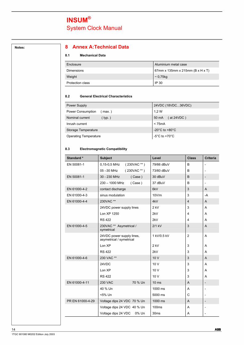
Notes: 8 Annex A:Technical Data 8.1 Mechanical Data Enclosure Aluminium metal case
Dimensions 67mm x 135mm x 215mm (B x H x T)
Weight ~ 0,75kg
Protection class IP 30 8.2 General Electrical Characteristics Power Supply 24VDC (18VDC...36VDC)
Power Consumption ( max. ) 1,2 W
Nominal current ( typ. ) 50 mA ( at 24VDC )
Inrush current < 75mA
Storage Temperature -20°C to +80°C
Operating Temperature -5°C to +70°C 8.3 Electromagnetic Compatibility Standard * Subject Level Class Criteria
EN 50081-1 0,15-0,5 MHz ( 230VAC ** ) 79/66 dBuV B -
05 –30 MHz ( 230VAC ** ) 73/60 dBuV B -
EN 50081-1 30 - 230 MHz ( Case ) 30 dBuV B -
230 – 1000 MHz ( Case ) 37 dBuV B -
EN 61000-4-2 contact discharge 6kV 3 A
EN 61000-4-3 sinus modulation 10V/m 3 -A
EN 61000-4-4 230VAC ** 4kV 4 A
24VDC power supply lines 2 kV 3 A
Lon XP 1250 2kV 4 A
RS 422 2kV 4 A
EN 61000-4-5 230VAC ** Asymetrical / symetrical
2/1 kV 3 A
24VDC power supply lines, asymetrical / symetrical
1 kV/0.5 kV 2 A
Lon XP 2 kV 3 A
RS 422 2kV 3 A
EN 61000-4-6 230 VAC ** 10 V 3 A
24VDC 10 V 3 A
Lon XP 10 V 3 A
RS 422 10 V 3 A
EN 61000-4-11 230 VAC 70 % Un 10 ms A -
40 % Un 1000 ms A -
<5% Un 5000 ms C -
PR EN 61000-4-29 Voltage dips 24 VDC 70 % Un 1000 ms A -
Voltage dips 24 VDC 40 % Un 100ms A -
Voltage dips 24 VDC 0% Un 30ms A -

INSUM® System Clock Manual
15 ABB 1TGC 901080 M0202 Edition July 2003
Notes: 8.4 Insulation test According IEC 60255-5 chap. 4 Subject Reference Point Level Class
24VDC Ground plane ± 0.8 kV 3
24VDC Internal bus lines ± 0.8 kV 3
Bus lines Ground plane ± 0.8 kV 3
8.5 Environmental Testing Subject International European
Vibration (sinusodial) IEC 255-21-1
Shock and bump IEC 255-21-2
Cold IEC 68-2-1 EN 60068-2-1
Dry heat IEC 68-2-2 EN 60068-2-2
Vibration (sinusodial) IEC 68-2-6 EN 60068-2-6
Damp heat, cyclic IEC 68-2-30 EN 60068-2-30

INSUM® System Clock Manual
16 ABB 1TGC 901080 M0202 Edition July 2003
Notes: 9 Annex B - INSUM Terms and Abbreviations
Abbreviation Term Explanation / Comments
Alarm Alarm is defined as status transition from any state to abnormal state. Status transition to abnormal state can be data crossing over the predefined alarm limit.
Backplane INSUM backbone, holds following INSUM devices: Router, Gateways, Clock, Power Supply. Part of the INSUM Communication Unit, see ICU
CA Control Access A function of INSUM system that allows definition of operating privileges for each device level (e.g. PCS, Gateway, field device)
CAT Control Access Table Table containing control access privileges
CB Circuit Breaker Circuit breaker unit (here: ABB SACE Emax with electronic release PR112-PD/LON)
CT Current Transformer Current Transformer
DCS Distributed Control System see also PCS
Eth Ethernet Ethernet is a local area network (LAN) technology. The Ethernet standard specifies the physical medium, access control rules and the message frames.
Event An event is a status transition from one state to another.
It can be defined as alarm, if the state is defined as abnormal or as warning as a pre-alarm state.
FD Field Device Term for devices connected to the LON fieldbus (e.g. motor control units or circuit breaker protection)
FU Field Unit see Field Device
GPI General Purpose Input Digital input on MCU for general use
GPO General Purpose Output Digital output on MCU for general use
GPS Global Positioning System System to detect local position, universal time and time zone, GPS technology provides accurate time to a system
GW Gateway A Gateway is used as an interface between LON protocol in INSUM and other communication protocols (e.g. TCP/IP, Profibus, Modbus)
HMI Human Machine Interface Generic expression for switchgear level communication interfaces to field devices, either switchboard mounted or hand held
ICU INSUM Communications Unit INSUM Communications Unit consists of devices such as backplane, Gateways, Routers, System Clock and Power Supply. It provides the communication interface within INSUM and between INSUM and control systems.
Formerly used expressions: SGC, SU
INSUM INSUM Integrated System for User optimized Motor Management. The concept of INSUM is to provide a platform for integration of smart components, apparatus and software tools for engineering and operation of the motor control switchgea
INSUM OS INSUM Operator Station Tool to parameterise, monitor and control devices in the INSUM system
ITS Integrated Tier Switch The Intelligent Tier Switch is an ABB SlimLine switch fuse with integrated sensors and microprocessor based electronics for measurement and surveillance
LON Local Operating Network LON is used as an abbreviation for LonWorks network. A variation of LON is used as a switchgear bus in the INSUM system
LonTalk LonTalk protocol Fieldbus communication protocol used in LonWorks networks
Notes:

INSUM® System Clock Manual
17 ABB 1TGC 901080 M0202 Edition July 2003
Notes: Abbreviation Term Explanation / Comments
LonWorks LonWorks network A communication network built using LonWorks network technology, including e.g. Neuron chip and LonTalk protocol
MCU Motor Control Unit Motor Control Unit is a common name for a product range of electronic motor controller devices (field device) in INSUM. A MCU is located in a MNS motor starter, where its main tasks are protection, control and monitoring of motor and the related motor starter equipment.
MMI Man Machine Interface The switchgear level INSUM HMI device to parameterize and control communication and field devices.
MNS MNS ABB Modular Low Voltage Switchgear
Modbus, Modbus RTU Fieldbus communication protocol
NV,nv LON Network Variable Network variable is a data item in LonTalk protocol application containing max. 31 bytes of data.
Nvi, nvi LON Network Variable input LON bus input variable
Nvo, nvo LON Network Variable output LON bus output variable
OS Operator Station see INSUM OS
PCS Process Control System High level process control system
PLC Programmable Local Controller
Low level control unit
PR Programmable Release Circuit breaker protection/release unit (here: ABB SACE Emax PR112-PD/LON)
Profibus DP Fieldbus communication protocol with cyclic data transfer
Profibus DP-V1 Fieldbus communication protocol, extension of Profibus DP allowing acyclic data transfer and multi master.
PTB Physikalisch-Technische Bundesanstalt
Authorized body in Germany to approve Ex-e applications.
PTC Positive Temperature Coefficient
A temperature sensitive resistor used to detect high motor temperature and to trip the motor if an alarm level is reached.
RCU Remote Control Unit Locally installed control device for motor starter, interacting directly with starter passing MCU for local operations.
Router Connection device in the LON network to interconnect different LON subnets. Part of the INSUM Communications Unit.
RTC Real Time Clock Part of the INSUM System Clock and and optionally time master of the INSUM system
SCADA Supervisory Control and Data Acquisition
SGC Switchgear Controller Former term used for INSUM Communications Unit
SU Switchgear Unit Former term used for INSUM Communications Unit
System Clock INSUM device providing time synchronisation between a time master and all MCUs. Part of the INSUM Communication Unit, see ICU
TCP/IP Transmission Control Protocol /Internet Protocol
TCP/IP is a high-level, connection oriented, reliable, full duplex communication protocol developed for integration of the heterogenous systems.
TFLC Thermal Full Load Current See MCU Parameter Description for explanation
TOL Thermal Overload See MCU Parameter Description for explanation
Trip A consequence of an alarm activated or an external trip command from another device to stop the motor or trip the circuit breaker.

INSUM® System Clock Manual
18 ABB 1TGC 901080 M0202 Edition July 2003
Notes: Abbreviation Term Explanation / Comments
UTC Coordinated Universal Time Coordinated Universal Time is the international time standard, formerly referred to as Greenwich Meridian Time (GMT). Zero (0) hours UTC is midnight in Greenwich England, which lies on the zero longitudinal meridian. Universal time is based on a 24 hours clock.
VU Voltage Unit Voltage measurement and power supply unit for MCU 2
Wink The Wink function enables identification of a device on the LON network. When a device receives a Wink-message via the fieldbus, it responds with a visual indication (flashing LED)
INSUM® System Clock Manual
19 ABB 1TGC 901080 M0202 Edition July 2003
Notes: Index
Abbreviations 16 Accuracy 11 Alarm functions 12 Configuration 9
of Hopf GPS System 9 of System Clock in Master Mode 9 of System Clock in Slave Mode 9, 10 Parameters of Hopf GPS System 13
Documents 4 Electrical Characteristics 14 Electromagnetic Compatibility 14 Environmental Testing 15 Hardware Characteristics 6 Indications 6 Installation
Self Installation 6 using Hopf GPS System 7 without GPS system 8
Insulation test 15 Lifesign signal 12 Maintenance functions 12 Master Mode 5, 8
Accuracy 11 Mechanical Data 14 Modes 5 Operation 5 Parameters 13 Purpose 4 Pushbuttons 6 Slave Mode 5, 8 Technical Data 14 Terms 16

Editor: DEAST/TBPublication No: 1TGC901080M0202
ABB Schaltanlagentechnik GmbHWallstadter Str. 59D - 68526 Ladenburg / Germany
Related Products, News, Local Contacts:www.abb.com/mns