SYSMAST - prosoft-technology.com · without receiving this configuration block. 2.2.3 File 30h and...
64
Corporate Office 1675 Chester Ave. Fourth Floor Bakersfield, CA 93301 (661) 716-5100 Phone (661) 716-5101 Fax 3100/3101-SYS Revision 1.5 3150/3151-SYS Revision 1.5 February 1996 Systronics Communication Module ______________________________________________________ USER MANUAL
Transcript of SYSMAST - prosoft-technology.com · without receiving this configuration block. 2.2.3 File 30h and...

Corporate Office1675 Chester Ave.
Fourth FloorBakersfield, CA 93301(661) 716-5100 Phone
(661) 716-5101 Fax
3100/3101-SYSRevision 1.5
3150/3151-SYSRevision 1.5
February 1996
Systronics Communication Module
______________________________________________________
USER MANUAL

TABLE OF CONTENTS
I. Card Overview ...................................................................................................... 1II. Systronics VSAT Programming Considerations.................................................... 3
2.1 Systronics VSAT Communications............................................................ 32.1.1 Command/Reply Cycle ............................................................... 32.1.2 Report by Exception ................................................................... 32.1.3 Command Types in the Systronics Slave ................................... 42.1.4 Command Error Checking .......................................................... 42.1.5 Data Integrity .............................................................................. 4
2.2 Module Memory Layout............................................................................. 42.2.1 Data Memory .............................................................................. 42.2.2 Communications Configuration Parameters ............................... 52.2.3 File 30h and 3Ch Configuration Values...................................... 5
III. SYS Module Theoretical Operation....................................................................... 73.1 Moving Data to the Module ....................................................................... 7
3.1.1 Communications Configuration Parameters ............................... 83.1.2 Moving Register Data (Block ID Codes 0-4) ............................... 113.1.3 File 30h and 3Ch Setup Data (Block ID Codes 5&6) .................. 13
3.2 Receiving Write Data from a Host............................................................. 143.2.1 Setpoint Select Command (File # 21h) ....................................... 143.2.2 Momentary Control Command (File # 1Dh) ................................ 153.2.3 Accumulator Reset Command (File # 44h) ................................. 153.2.4 Multi-Streaming File Data Setup (File #30h) ............................... 163.2.5 VSAT Timer File Setup ( File #3Ch) ........................................... 163.2.6 Write Real Time Clock ( File #05h) ............................................. 163.2.7 Pulse Train Control Select File ( File #2Ch)................................ 16
3.3 Module Status ........................................................................................... 173.3.1 Slave Error Code Table .............................................................. 173.3.2 Error Status Codes ..................................................................... 19
IV Configuring the Module......................................................................................... 214.1 Hardware Overview................................................................................... 214.2 Module Jumper Configurations ................................................................. 21
4.2.1 3100/3101 for the 1771 Platform................................................ 214.2.2 3150/3151 for the 1746 Platform................................................ 22
4.3 Firmware Installation Procedure ( 3101 & 3151 ) ...................................... 234.3.1 1771-DB Revision B Module....................................................... 234.3.2 1746-BAS Module ...................................................................... 23
V. Systronics Slave Commands ................................................................................ 255.1 Systronics Command Structure................................................................. 25
5.1.1 File # 14h - Read Analog Data ................................................... 255.1.2 File # 19h - Read Status Data .................................................... 255.1.3 File # 47h - Read Current End of Batch Data - 32 bit ................. 255.1.4 File # 37h - Read Accumulator Data - 32 bit............................... 255.1.5 File # 1Dh - Momentary Control Select ....................................... 255.1.6 File # 21h - Setpoint Select ........................................................ 265.1.7 File # 23h - Execute Selected Control File.................................. 265.1.8 File # 30h - Multi-file Streaming Data Setup ............................... 26

5.1.9 File # 3Fh - Multi-file Streaming Data ......................................... 265.1.10 File # 3Ch - VSAT Timer Setup ................................................ 265.1.11 File # 3Eh - 20 msec Timer....................................................... 265.1.12 File # 41h - Analog Deviation Limits ......................................... 265.1.13 File # 44h - Accumulator Reset Commands ............................. 275.1.14 File # 4Bh - Tank Levels ........................................................... 275.1.15 File # 2Ch - Pulse Train Control Select File .............................. 27
VI Hardware Diagnostics ........................................................................................... 296.1 3100/3101 PLC Platform........................................................................... 296.2 3150/3151 SLC Platform........................................................................... 30
VII Support, Service and Warranty............................................................................. 337.1 Technical Support ..................................................................................... 337.2 Service and Repair.................................................................................... 337.3 Warranty ................................................................................................... 34
7.3.1 General Warranty Policy............................................................. 347.3.2 Limitation of Liability ................................................................... 347.3.3 Hardware Product Warranty Details ........................................... 34
APPENDICES
Appendix APLC-5 Example Ladder LogicSLC Example Ladder Logic
Appendix BDefinitions of RS-232C Handshaking SignalsRS-232C Cable ConfigurationRS-422/RS-485 Cable Configuration
Appendix C3100/3101 Jumper diagrams3150/3151 Jumper diagrams
Appendix DProduct Revision History
Appendix ESystronics Protocol Specification
(Provided by Conoco)

Revised 06/26/98 1
I. Card Overview
The ProSoft Technology, Inc. Systronics VSAT Slave firmware upgrade givesAllen-Bradley 1771 and 1746 I/O compatible processors the ability to interfaceto a Systronics VSAT Master device on up to two ports per module. Theproduct includes the following capabilities:
• Foxboro / Systronics Minimote RTU Protocol
• Two fully configurable serial ports, each capable of supportingthe full implementation of the protocol
• Binary Data Stream with CRC-16 Error Checking
• Supported File Numbers:14h Analog Data19h Status Data37h Accumulator Data - 32 bit1Dh Momentary Control Select21h Setpoint Select23h Execute Selected Control File2Ch Pulse Train Control File30h Multi-file Streaming Data Setup3Fh Multi-file Streaming Data3Ch VSAT Timer Setup3Eh 20 msec Timer41h Analog Deviation Limits44h Accumulator Reset Commands47h 32 bit Accumulator Current End of Batch4Bh Tank Levels
• Master Broadcast Addressing to Slaves (#127)
• Software configuration (From PLC)Address : 1 to 126Parity : None, odd, or even,Stop Bit : 1 or 2Baud Rate : 300 TO 38,400
• Hardware RS-232C handshaking for modem and radioapplications
• RS-422/RS-485 compatible for multi-drop applications

2 Revised 06/26/98
(This page intentionally left blank)
Revised 06/26/98 3
II. Systronics VSAT Programming Considerations
2.1 Systronics VSAT CommunicationsThe ProSoft Systronics VSAT Slave module runs the SystronicsMinimote protocol. This capability allows the module to communicatedata from a PLC/SLC to a Systronics Master and vice-versa. Themodule supports both point-to-point as well as multi-dropimplementations.
The following discusses the functional capabilities of the Prosoft card.
2.1.1 Command/Reply CycleSuccessful communications between a Systronics Slave and aMaster will always consist of the following two transactions:
Command: Message from master giving instruction to slave.
Reply: Response to command.
A slave station will respond to a master issued command inseveral ways.
Data Message: If the command was executed by the slave,the response message will include the data requested, or anacknowledgement that the command was executed.
Error Message: If the command could not be executed bythe slave, for whatever reason, an error response message istransmitted to the master.
No Reply: If the master does not detect a reply withinits timeout period, the master should re-transmit the command,before a time out error is issued. If the Slave could not decodethe message or an error occurred preventing the Slave fromrecognizing the message, no response will be issued.
2.1.2 Report by ExceptionThe Systronics Slave may also report by exception. Any changenoted in the Status bits (19h) or Analog values exceedingdeviation limits (14h) will generate a message from the slave tothe master. This message will transmit the current Status orcurrent Analog data to the master.
Timing for the transmission of these messages is configuredusing file 3Ch. File 3Fh is multiple file report command which willreturn all data on a periodic basis, as determined by the userconfiguration in file 3Ch.
4 Revised 06/26/98
2.1.3 Command Types in the Systronics SlaveThe Systronics Slave can respond to two types of commandsfrom the master; read data and write data. These are discussedcollectively in Section V since some command types are bothread and write types.
2.1.4 Command Error CheckingWhen the Systronics Slave cannot execute a command, an errorcode is generated and returned to the master. Error codesgenerated at the slave will usually be indicative of an illegalfunction, an illegal address, bad data, or the inability to completea transaction because of a network problem.
2.1.5 Data IntegrityAs in all good protocols, there must exist a level of data integritychecking to verify, with some degree of assurance, the quality ofthe transmitted data. The Systronics protocol supports two typesof error checking:
• 16 bit cyclic redundancy check (CRC-16)• One bit parity check
A key criteria to keep in mind when implementing anetwork is to make sure that the master and all the slavesare configured with the same error checking method.
CRC-16: When the master generates a message, a 16 bit CRCvalue is added to the end of the transmitted packet. The CRCvalue is generated using a series of bit shifts and manipulations.The receiving station executes the same calculation on the dataand verifies the transmitted CRC. Any discrepancy will cause themessage to be disregarded.
Parity: Parity checking can be added as an additional level ofdata security. If parity checking is selected, even or odd paritycan be implemented.
2.2 Module Memory LayoutThis section explains the different segments of the memory which areutilized in the PLC and in the Systronics Slave module.
2.2.1 Data MemoryData is transferred from the PLC/SLC to the moduleasynchronously from the Master's data read requests. Thisallows the application ladder logic to manipulate and position thedata as needed before transfer to the module. Since the modulestores the data from the ladder logic in local memory, readrequests from the Master are serviced immediately.
Revised 06/26/98 5
The data registers are moved over the backplane between themodule and the processor using the standard Block Transferread and write functions, in the case of a PLC, and M0/M1 filetransfers in the case of an SLC.
The module controls the data which is transferred from themodule to the PLC/SLC during a read (BTR or M1 instruction)from the module. Being a slave module, the only time valid 'data'is transferred to the ladder logic is when a write command isissued from the Master.
When writing data from the ladder logic to the module (BTW orM0 instruction), the ladder logic controls the data written to themodule. Appendix A contains a PLC5 and a SLC programshowing an example of the logic to transfer data registers to andfrom the module. Section III discusses the transfer mechanism indetail, as well as several important relationships between PLC /SLC addressing, module addressing, and protocol addressing.
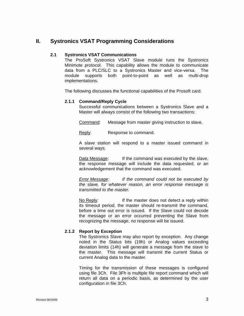
The relationship between the Systronics addressing and theprocessor’s addressing is shown in the figure below. Theprocessor programs in Appendix A are designed to support thisdata table configuration. In order to modify the flow and / ordirections of the data, the example ladder logic needs to bemodified.
Filetype File #’s Valid Addresses PLC / SLC Addresses16 bit registers 14h 0 - 61 N12:0 - N12:4916 bit binary 19h 0 - 123 N12:50 - N12:9932 bit acc EOBatch 47h 0 - 15 N12:100 - N12:14932 bit accumulator 37h 0 - 31 N12:150 - N12:199Tank Levels 4Bh 0 - 31 N12:200 - N12:249Momentary Control 1Dh Bit:0 - 255 B13:0 - B13:15
Card 0 - 15Setpoint Select 21h Reg:0 - 4095 N11:0 - N11:32Accumulator Reset 44h 1 -2 B13:16 - B13:17
Relationship between Systronics addressing & PLC / SLC DataTables
2.2.2 Communications Configuration ParametersThe communications configuration parameter data block containsthe information necessary for the module to set up the module'scommunications ports. On power up, the module will not proceedwithout receiving this configuration block.
2.2.3 File 30h and 3Ch Configuration ValuesThe configuration values for File 30h (Multi-File Streaming DataSetup) and File 3Ch (VSAT Timer Setup) are stored in theprocessor data image. This image may be edited manually aswell as being updated by downloads from a host.

6 Revised 06/26/98
(This page intentionally left blank)

Revised 06/26/98 7
III. SYS Module Theoretical Operation
Data transfers between the processor and the ProSoft Technology moduleoccur using the Block Transfer commands, in the case of the PLC, and M0/M1data transfer commands, in the case of the SLC. These commands transfer upto 64 physical registers per transfer. The logical data length changesdepending on the data transfer function.
The following discussion details the data structures used to transfer the differenttypes of data between the ProSoft Technology module and the processor. Theterm 'Block Transfer' is used generically in the following discussion to depict thetransfer of data blocks between the processor and the ProSoft Technologymodule. Although a true Block Transfer function does not exist in the SLC, wehave implemented a pseudo-block transfer command in order to assure dataintegrity at the block level. Examples of the PLC and SLC ladder logic areincluded in Appendix A.
In order for the ProSoft Technology module to function, the PLC mustbe in the RUN mode, or in the REM RUN mode. If in any other mode(Fault/PGM), the block transfers between the PLC and the module willstop, and communications will halt until block transfers resume. [Note: PLC Version ONLY ]
3.1 Moving Data to the Module
This section discusses how to transfer Data, Status and Analog data tothe ProSoft module.
Data transfer to the module from the processor is executed through theBlock Transfer Write function. The different types of data which aretransferred require slightly different data block structures, but the basicdata structure is:
WORD DESCRIPTION0 Block ID code1-63 Data
In a PLC, the BTW length must be configured for 64 words. In anSLC, the M0 file should be configured for 64 words. Otherwise moduleoperation will be unpredictable.
where:
BLOCK ID CODE: A block identifier code between 0-6 and 255 invalue. This code is used by the ProSoft module to determine what to dowith the data block. Valid codes are:
8 Revised 06/26/98
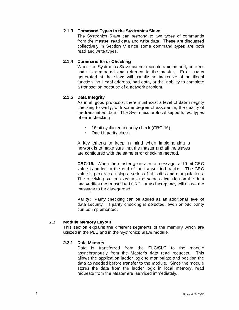
CODE DESCRIPTION0-6 File and Data Identifier
255 Communication Configuration Parameters
DATA: The data to be written to the module. The structure of the datais dependent on the block ID code. Sections 3.1.1 and 3.1.2 providedetails on the different structures.
3.1.1 Communications Configuration ParametersThe ProSoft Technology firmware communication parametersmust be configured at least once when the card is first poweredup, and any time thereafter when the parameters must bechanged.
On power up, the module enters into a logical loop waiting toreceive configuration data from the processor. While waiting, themodule sets the first word of the BTR buffer to 255, telling theprocessor that the module must be configured before anythingelse will be done. The module will continuously perform blocktransfers until the communications configuration parametersblock is received. Upon receipt, the module will begin execution.
Transferring the Communications Configuration Parametersto the module will force a reset of the communication port, aswell as dropping DTR to reset any attached hardware.
The configuration data block structure which must be transferredfrom the processor to the module is as follows:
DataWord Description
Block ID Header = 255Port 1
0 N[]:0 Port Configuration Word1 N[]:1 Address (if configured as a Slave)2 N[]:2 Baud Rate3 N[]:3 RTS to TxD Delay
4 N[]:4 RTS off Delay5 N[]:5 Message Response Timeout6 N[]:6 Inter-character timing7 N[]:7 Momentary Select Count8 N[]:8 Setpoint Select Count9 N[]:9 Setpoint Table Initialize
Port 210 N[]:10 Port Configuration Word11 N[]:11 Address (if configured as a Slave)12 N[]:12 Baud Rate13 N[]:13 RTS to TxD Delay
Revised 06/26/98 9
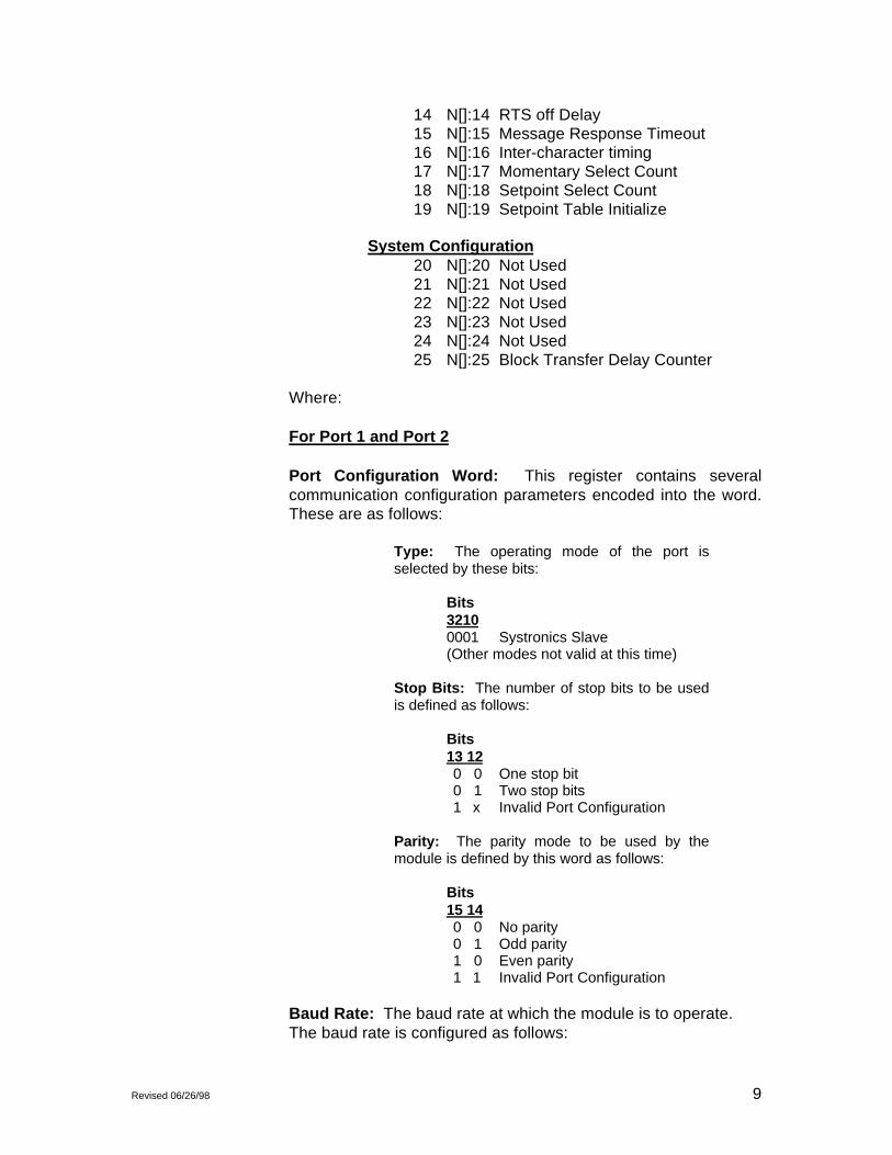
14 N[]:14 RTS off Delay15 N[]:15 Message Response Timeout16 N[]:16 Inter-character timing17 N[]:17 Momentary Select Count18 N[]:18 Setpoint Select Count19 N[]:19 Setpoint Table Initialize
System Configuration20 N[]:20 Not Used21 N[]:21 Not Used22 N[]:22 Not Used23 N[]:23 Not Used24 N[]:24 Not Used25 N[]:25 Block Transfer Delay Counter
Where:
For Port 1 and Port 2
Port Configuration Word: This register contains severalcommunication configuration parameters encoded into the word.These are as follows:
Type: The operating mode of the port isselected by these bits:
Bits32100001 Systronics Slave(Other modes not valid at this time)
Stop Bits: The number of stop bits to be usedis defined as follows:
Bits13 120 0 One stop bit0 1 Two stop bits1 x Invalid Port Configuration
Parity: The parity mode to be used by themodule is defined by this word as follows:
Bits15 140 0 No parity0 1 Odd parity1 0 Even parity1 1 Invalid Port Configuration
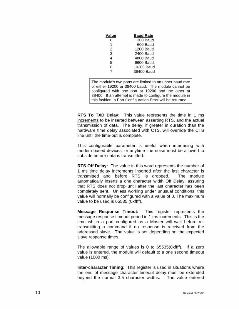
Baud Rate: The baud rate at which the module is to operate.The baud rate is configured as follows:
10 Revised 06/26/98
Value Baud Rate 0 300 Baud 1 600 Baud 2 1200 Baud 3 2400 Baud 4 4800 Baud 5 9600 Baud 6 19200 Baud 7 38400 Baud
The module’s two ports are limited to an upper baud rateof either 19200 or 38400 baud. The module cannot beconfigured with one port at 19200 and the other at38400. If an attempt is made to configure the module inthis fashion, a Port Configuration Error will be returned.
RTS To TXD Delay: This value represents the time in 1 msincrements to be inserted between asserting RTS, and the actualtransmission of data. The delay, if greater in duration than thehardware time delay associated with CTS, will override the CTSline until the time-out is complete.
This configurable parameter is useful when interfacing withmodem based devices, or anytime line noise must be allowed tosubside before data is transmitted.
RTS Off Delay: The value in this word represents the number of1 ms time delay increments inserted after the last character istransmitted and before RTS is dropped. The moduleautomatically inserts a one character width Off Delay, assuringthat RTS does not drop until after the last character has beencompletely sent. Unless working under unusual conditions, thisvalue will normally be configured with a value of 0. The maximumvalue to be used is 65535 (0xffff).
Message Response Timout: This register represents themessage response timeout period in 1 ms increments. This is thetime which a port configured as a Master will wait before re-transmitting a command if no response is received from theaddressed slave. The value is set depending on the expectedslave response times.
The allowable range of values is 0 to 65535(0xffff). If a zerovalue is entered, the module will default to a one second timeoutvalue (1000 ms).
Inter-character Timing: This register is used in situations wherethe end of message character timeout delay must be extendedbeyond the normal 3.5 character widths. The value entered

Revised 06/26/98 11
represents the number of 1 ms intervals of ‘no transmission’which will be counted prior to accepting a message. Thisparameter will be useful in satallite or packet radio installationwhere a data transmission may be split between two packets.Increasing this value beyond the system’s packet handling timewill eliminate timeout errors.
Momentary Select Count: Valid values are from 0 - 32. Thisparameter informs the Systronics host how many 8 point cards ofI/O this station contains.
Setpoint Select Count: Valid values range from 0 -32. Thisparameter informs the Systronics host of how many setpoints thisstation will accept.
Setpoint Table Initialization: If equal to 1 (or LSB = 1),initializes setpoint write table to 0’s.
System Configuration
Block Transfer Delay Counter: This value is used by themodule to slow down the block transfer loading between themodule and the processor. Excessive Block Transfers can slowdown the response time of the SYS’s communication ports. Thisparameter has been provided to allow the Block Transfer timingto be determined on an application basis. A value of 0 isnormally used at the factory and is recommended as a startingpoint.
3.1.2 Moving Register Data (Block ID Codes 0-4)The movement of data to the module is executed through a blocktransfer write with the following structure:
Word 0 : Block IDWord 1 : Entity CountWord 2-63 : Data
where:
Block ID: The Block ID is used by the module to decodewhich file the data is intended for. The relationship betweenblock ID number and file type is as follows:
Block ID File Type0 14h - Analog Data1 19h - Status Data2 47h - 32 bit Accum Current End of Batch3 37h - 32 bit Accumulator4 4Bh - Tank Level - BCD

12 Revised 06/26/98
Entity Count: This value represents the size of the file data blockthat is available to the master. The master uses this value todetermine how many registers values to request. Valid valuesare as follows:
Block ID Entity Count0 0 to 621 0 to 1242 0 to 313 0 to 314 0 to 31
Data: This field contains the data that is to be transmitted to themaster if a request is received. The data structures are asfollows:
Block ID 0: Analog DataWord 2: 16 bit integer dataWord 3: 16 bit integer dataWord 63: 16 bit integer data
Block ID 1: Status DataThe status data is arranged as follows within a word, starting atword 2:
Word X : High byte : Entry #1 Hold forLow byte : Entry #2 verification
Block ID 2: 32 bit Accumulator Current End of BatchWord 2: Rollover Flags (1-16)Word 3: Shift Flags (1-16)Word 3: Accum # 1 ( Value / 10000)Word 4: Accum # 1 ( Value MOD 10000)Word 5: Accum # 2 ( Value / 10000)Word 6: Accum # 2 ( Value MOD 10000)Word 34: Accum # 16( Value / 10000)Word 35: Accum # 16( Value MOD 10000)
Block ID 3: 32 Bit AccumulatorWord 2: Accum # 1 ( Value / 10000)Word 3: Accum # 1 ( Value MOD 10000)Word 4: Accum # 2 ( Value / 10000)Word 5: Accum # 2 ( Value MOD 10000)Word 62: Accum # 31( Value / 10000)Word 63: Accum # 31( Value MOD 10000)
Block ID 4: Tank LevelWord 2: Level #1 - 16ths of inchesWord 3: Level #2 - 16ths of inchesWord 4: Level #3 - 16ths of inchesWord 5: Level #4 - 16ths of inchesWord 31: Level #31 - 16ths of inchesWord 32: Level #32 - 16ths of inches

Revised 06/26/98 13
3.1.3 File 30h and 3Ch Setup Data (Block ID Codes 5&6)The movement of data to the module is executed through a blocktransfer write with the following structure:
Word 0 : Block ID 5 & 6Word 1-51 : Data Block
where:
Block ID: The Block ID is used by the module to decodewhich file the data is intended for. The relationship betweenblock ID number and file type is as follows:
Block ID File Type5 30h - Multi-File Streaming Data Setup6 3Ch- VSAT Timer Setup
Data: This field contains the data that is to be transmitted to themaster if a request is received. The data structures are asfollows:
Block ID 5: Setup Data for Port 1 and 2Word 1 File Number to read - Entry 0, Port 1Word 2 Starting Entry to read - Entry 0, Port 1Word 3 Number of Entries - Entry 0, Port 1 - -Word 22 File Number to read - Entry 7, Port 1Word 23 Starting Entry to read - Entry 7, Port 1Word 24 Number of Entries - Entry 7, Port 1Word 25 File Number to read - Entry 0, Port 2Word 26 Starting Entry to read - Entry 0, Port 2Word 27 Number of Entries - Entry 0, Port 2 - -Word 46 File Number to read - Entry 7, Port 2Word 47 Starting Entry to read - Entry 7, Port 2Word 48 Number of Entries - Entry 7, Port 2
Block ID 6: VSAT Timer Setup - Port 1 and 2Word 1 File Number to send - Entry 0, Port 1Word 2 Preset Timer Value - Entry 0, Port 1 - -Word 15 File Number to send - Entry 7, Port 1Word 16 Preset Timer Value - Entry 7, Port 1Word 17 File Number to send - Entry 0, Port 2Word 18 Preset Timer Value - Entry 0, Port 2 - -Word 31 File Number to send - Entry 7, Port 2Word 32 Preset Timer Value - Entry 7, Port 2

14 Revised 06/26/98
3.2 Receiving Write Data from a Host
This section discusses how to get data written to the ProSoft module bya Master into the processor.
The transfer of data from the ProSoft Technology module to theprocessor is executed through the Block Transfer Read function. Threedifferent types of data are moved from the module into the processor.
The data structure for the block transfer depends on the type of blockdata. Note that the module supports the direct control and select modesof writes.
In a PLC, the BTR length must be configured for 64 words.In a SLC, the M1 file must be configured for 64 words.Otherwise module operation will be unpredictable.
3.2.1 Setpoint Select Command (File # 21h)In order to allow the transfer of variable length data fields into anypart of the Processor’s data table (i.e.: to support variable lengthregister writes) the Read data block from the module is structuredas follows:
WORD DESCRIPTION 0 Setpoint Write (bit 0) = 1 1 Register address 2 - 33 Setpoint Data Values
where:
Register Write: This word (bit) is used to tell the Processorthat a new register write command has been issued by a Masterand to transfer the data that follows into the Processor’s datatable. When the write command is received by the slave module,bit 0 of the word 0 is set. Once the transfer is complete, theSystronics module resets the bit.
Bit 0 can then be used by the Processor logic to condition thetransfer of data from the BTR buffer into the Processor’s datatable. Note that the Processor application program need notreset the bit.
Register Address: This register represents the offset addressinto which the write data block will start to be written. Thisregister can be used to point directly into the Processor’s datatable, as in the Appendix A example. The register address iscalculated as follows:
Address: (I/O card x 2) + (point - 1)

Revised 06/26/98 15
Data: A table of up to 32 values containing the results of thewrite commands from the Systronics master. Write commandsfrom a host are received into this table at the addressed position.The entire table is moved with each write. This table may beinitialized to 0 by setting the Setpoint Table Initialization Bit andissuing a module configuration.
3.2.2 Momentary Control Command (File # 1Dh)In order to set a bit within the Processor’s data table, the ReadData Block has been structured as follows:
WORD DESCRIPTION 0 Bit Set (bit 1) = 2 1 - 16 Binary image (16 words)
where:
BIT SET: Word 0, bit 1 of the data block is used to tell theProcessor that a new bit set/reset command has been receivedfrom the master. When the “Bit Set/Reset” bit is set, (bit 1 = 1),the ladder logic is enabled to act on the Processor’s data table.The exact action that the Processor will take is dependent on thenext two words. Note that the Systronics slave module will resetthis bit after the transfer, and therefore the application need notreset the bit.
BINARY IMAGE: The bit wrtie command is received by themodule and is used to set the appropriate bit in the 16 wordimage. The active 16 words are moved to the ladder logic. Oncethe block has been moved, the bit is immediately reset in themodule’s image so that on the next write command the lastwritten bit will no longer be set.
3.2.3 Accumulator Reset Command (File # 44h)In order to reset the 16 and 32 bit Accumulators, the Read DataBlock is structrured as follows:
WORD DESCRIPTION 0 Bit Set (bit 2) = 4 1-2 Reset Accumulator Bit Image
where:
BIT SET: Word 0, bit 2 of the data block is used to tell theProcessor that an Accumulator Reset command has beenreceived from the Systronics master.
RESET ACCUMULATOR BIT IMAGE: When an AccumulatorReset command is received by the module, a bit in the ‘Reset BitAccumulator Image’ is set, corresponding to the addressed

16 Revised 06/26/98
accumulator. The ladder logic should use the bit, with a ‘ONS’(One Shot) to trigger the reset logic. Once the block has beenmoved, the bit is immediately reset in the module’s image so thaton the next write command the last written bit will no longer beset.
3.2.4 Multi-Streaming File Data Setup (File #30h)When a File 30h write is received from the host, whether a partialfile write or a complete file write, the File 30h image that ismaintained in the module is moved down to the processor. Theladder logic can selectively store this data to assure that underpower up conditions, the slave still maintains reportingcapabilities. (Note that the data for both ports is moved to theprocessor no matter which port the write comes in on).
WORD DESCRIPTION0 File 30h write = 51-48 Per structure detailed in Section 3.1.3
3.2.5 VSAT Timer File Setup ( File #3Ch)When a File 3Ch write is received from the host, whether a partialfile write or a complete file write, the File 3Ch image that ismaintained in the module is moved down to the processor. Theladder logic can selectively store this data to assure that underpower up conditions, the slave still maintains reportingcapabilities. (Note that the data for both ports is moved to theprocessor no matter which port the write comes in on).
WORD DESCRIPTION0 File 3Ch write = 61-32 Per structure detailed in Section 3.1.3
3.2.6 Write Real Time Clock ( File #05h)When a File 05h write is received from the host, whether a partialfile write or a complete file write, the File 05h image that ismaintained in the module is moved down to the processor. Theladder logic can selectively store this data to assure that underpower up conditions, the slave still maintains reportingcapabilities. (Note that the data for both ports is moved to theprocessor no matter which port the write comes in on).
WORD DESCRIPTION0 File 05h write = 71-32 Per structure detailed in Section 3.1.3
3.2.7 Pulse Train Control Select File ( File #2Ch)When a File 2Ch write is received from the host, the datareceived from the host is moved to the ladder logic. (Note that the

Revised 06/26/98 17
data for both ports is moved to the processor no matter whichport the write comes in on).
WORD DESCRIPTION0 File 2Ch write = 81 Point Address2 Pulse Train Count3 Pulse train period
Note that the SYS module is limited to receiving one Pulsecommand per transmission.
Point Address: This register represents the point addresswhich is being commanded to pulse by the host. This registercan be used to point directly into the Processor’s data table. Theregister address is calculated as follows:
Address: (I/O card x 2) + (point - 1)
Pulse Train Count: Number of pulse cycles as commanded bythe host
Pulse Train Period: The pulse period, in milliseconds, ascommanded by the host
3.3 Module StatusThis section discusses how to get module status data from the moduleinto the processor.
3.3.1 Slave Error Code TableThe SYS Module monitors the status of all Slave port commands.This status is communicated to the processor in the form of aSlave Error Code Table.
The Slave Error Code Table is initialized to zero on power up,and every time the module receives the 255 configuration datablock.
The Slave Error Table is a 20 word block. The Table is returnedto the ladder logic anytime the BTR Block ID is equal to 0.
The structure of the data block is as follows:
WORD DESCRIPTIONPort 10 Current port status1 Last transmitted error condition2 Total Messages to this slave3 Total Msg responses from this slave4 Total Msgs seen by this slave
18 Revised 06/26/98
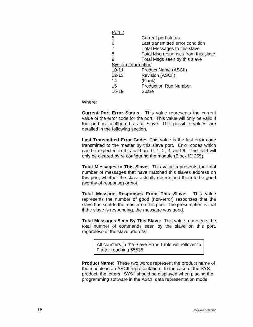
Port 25 Current port status6 Last transmitted error condition7 Total Messages to this slave8 Total Msg responses from this slave9 Total Msgs seen by this slaveSystem Information10-11 Product Name (ASCII)12-13 Revision (ASCII)14 (blank)15 Production Run Number16-19 Spare
Where:
Current Port Error Status: This value represents the currentvalue of the error code for the port. This value will only be valid ifthe port is configured as a Slave. The possible values aredetailed in the following section.
Last Transmitted Error Code: This value is the last error codetransmitted to the master by this slave port. Error codes whichcan be expected in this field are 0, 1, 2, 3, and 6. The field willonly be cleared by re configuring the module (Block ID 255).
Total Messages to This Slave: This value represents the totalnumber of messages that have matched this slaves address onthis port, whether the slave actually determined them to be good(worthy of response) or not.
Total Message Responses From This Slave: This valuerepresents the number of good (non-error) responses that theslave has sent to the master on this port. The presumption is thatif the slave is responding, the message was good.
Total Messages Seen By This Slave: This value represents thetotal number of commands seen by the slave on this port,regardless of the slave address.
All counters in the Slave Error Table will rollover to0 after reaching 65535
Product Name: These two words represent the product name ofthe module in an ASCII representation. In the case of the SYSproduct, the letters ‘ SYS ‘ should be displayed when placing theprogramming software in the ASCII data representation mode.

Revised 06/26/98 19
Revision : These two words represent the product revision levelof the firmware in an ASCII representation. An example of thedata displayed would be ‘1.20’ when placing the programmingsoftware in the ASCII data representation mode.
Blank: Not used at this time
Production Run Number: This number represents the ‘batch’number that your particular chip belongs to. This number shouldappear as a number equal or greater than 1. This should helpthe factory determine when the User’s chip was created.
3.3.2 Error Status CodesThe Error Codes returned in the Slave Error Code Table reflectthe outcome of the commands and responses executed by themodule. Note that in all cases, if a zero is returned, there wasnot an error. Valid Error Status Codes are as follows:
Code Description0 All OK
The module is operating as desired.
1 Illegal FunctionAn illegal function code request has beenreceived from the master
253 Port 1 DCD not ActivePort 1 of the module has been designatedthe VSAT port and requires the DCD signalto operate correctly
254 Checksum ErrorThe slave determined that the messagechecksum was in error, and thereforediscarded the message
255 TX Hardware Time-outA time-out has occurred in the transmissionof the command from the master, and thecommand has been aborted. This error isusually an indication that the CTS signal isnot being received by the module.

20 Revised 06/26/98
(This page intentionally left blank)
Revised 06/26/98 21
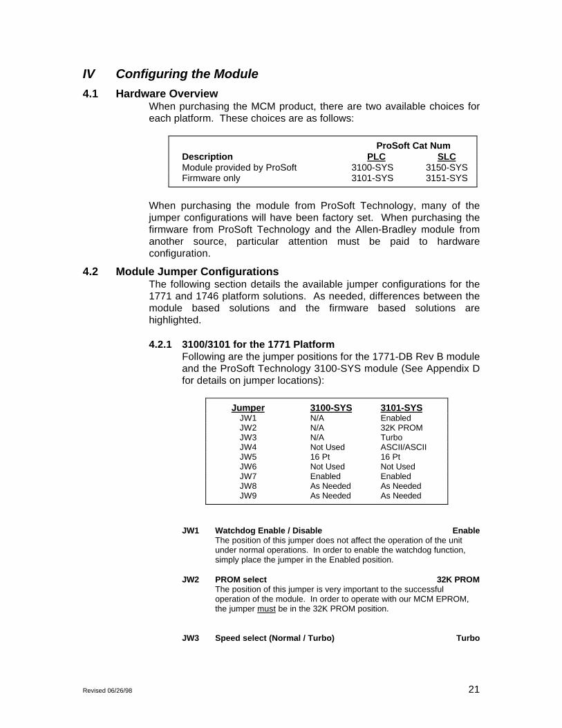
IV Configuring the Module
4.1 Hardware OverviewWhen purchasing the MCM product, there are two available choices foreach platform. These choices are as follows:
ProSoft Cat NumDescription PLC SLCModule provided by ProSoft 3100-SYS 3150-SYSFirmware only 3101-SYS 3151-SYS
When purchasing the module from ProSoft Technology, many of thejumper configurations will have been factory set. When purchasing thefirmware from ProSoft Technology and the Allen-Bradley module fromanother source, particular attention must be paid to hardwareconfiguration.
4.2 Module Jumper ConfigurationsThe following section details the available jumper configurations for the1771 and 1746 platform solutions. As needed, differences between themodule based solutions and the firmware based solutions arehighlighted.
4.2.1 3100/3101 for the 1771 PlatformFollowing are the jumper positions for the 1771-DB Rev B moduleand the ProSoft Technology 3100-SYS module (See Appendix Dfor details on jumper locations):
Jumper 3100-SYS 3101-SYSJW1 N/A EnabledJW2 N/A 32K PROMJW3 N/A TurboJW4 Not Used ASCII/ASCIIJW5 16 Pt 16 PtJW6 Not Used Not UsedJW7 Enabled EnabledJW8 As Needed As NeededJW9 As Needed As Needed
JW1 Watchdog Enable / Disable EnableThe position of this jumper does not affect the operation of the unitunder normal operations. In order to enable the watchdog function,simply place the jumper in the Enabled position.
JW2 PROM select 32K PROMThe position of this jumper is very important to the successfuloperation of the module. In order to operate with our MCM EPROM,the jumper must be in the 32K PROM position.
JW3 Speed select (Normal / Turbo) Turbo
22 Revised 06/26/98
The position of this jumper does not affect the operation of the unitunder normal operations. Unless there are reasons not to operate inthe Turbo mode, we recommend operating in the Turbo mode.
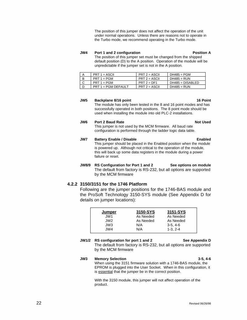
JW4 Port 1 and 2 configuration Position AThe position of this jumper set must be changed from the shippeddefault position (D) to the A position. Operation of the module will beunpredictable if the jumper set is not in the A position.
A PRT 1 = ASCII PRT 2 = ASCII DH485 = PGMB PRT 1 = PGM PRT 2 = ASCII DH485 = RUNC PRT 1 = PGM PRT 2 = DF1 DH485 = DISABLEDD PRT 1 = PGM DEFAULT PRT 2 = ASCII DH485 = RUN
JW5 Backplane 8/16 point 16 PointThe module has only been tested in the 8 and 16 point modes and hassuccessfully operated in both positions. The 8 point mode should beused when installing the module into old PLC-2 installations.
JW6 Port 2 Baud Rate Not UsedThis jumper is not used by the MCM firmware. All baud rateconfiguration is performed through the ladder logic data table.
JW7 Battery Enable / Disable EnabledThis jumper should be placed in the Enabled position when the moduleis powered up. Although not critical to the operation of the module,this will back up some data registers in the module during a powerfailure or reset.
JW8/9 RS Configuration for Port 1 and 2 See options on moduleThe default from factory is RS-232, but all options are supportedby the MCM firmware
4.2.2 3150/3151 for the 1746 PlatformFollowing are the jumper positions for the 1746-BAS module andthe ProSoft Technology 3150-SYS module (See Appendix D fordetails on jumper locations):
Jumper 3150-SYS 3151-SYSJW1 As Needed As NeededJW2 As Needed As NeededJW3 N/A 3-5, 4-6JW4 N/A 1-3, 2-4
JW1/2 RS configuration for port 1 and 2 See Appendix DThe default from factory is RS-232, but all options are supportedby the MCM firmware
JW3 Memory Selection 3-5, 4-6When using the 3151 firmware solution with a 1746-BAS module, theEPROM is plugged into the User Socket. When in this configuration, itis essential that the jumper be in the correct position.
With the 3150 module, this jumper will not affect operation of theproduct.

Revised 06/26/98 23
JW4 Mode Configuration 1-3, 2-4When using the 3151 firmware solution with a 1746-BAS module, it isessential that the jumper be in the correct position.
With the 3150 module, this jumper will not affect operation of theproduct.
4.3 Firmware Installation Procedure ( 3101 & 3151 )The following section details the available jumper configurations for the1771 and 1746 platform solutions. As needed, differences between themodule based solutions and the firmware based solutions arehighlighted.
4.3.1 1771-DB Revision B ModuleThe firmware installation steps are as follows:
1. Remove the card cover from the module
2. Plug the ProSoft Technology EPROM into themodule's User Socket. Align the notches on theEPROM plastic carrier with the notches in theUser socket. Make sure the EPROM is wellseated
3. Replace the card cover
4. Turn the module over and locate the identi-fication sticker in the unused indent. Thissticker will be important should the module everrequire service.
4.3.2 1746-BAS ModuleThe firmware installation steps are as follows:
1. Plug the ProSoft Technology EPROM into themodule's User Socket. Align the notches on theEPROM plastic carrier with the notches in theUser socket. Make sure the EPROM is wellseated
2. Remove the plastic lens cover from the 1746-BAS module and slip on the new cover providedwith the firmware. Make sure the cover is firmlyaffixed to the module
Once the firmware has been installed and the module’s jumpershave been verified, the hardware is ready to be inserted into theI/O rack.

24 Revised 06/26/98
(This page intentionally left blank)

Revised 06/26/98 25
V. Systronics Slave Commands
The ProSoft Technology Systronics Slave module supports several data readand write commands. The decision on which command to use is madedepending on the type of data being addressed, and the level of Systronicssupport in the slave and master equipment. The following sections detail thedifferent commands supported by the module.
5.1 Systronics Command StructureThe Systronics Slave module supports the following commands. Asstated in earlier sections, the data for responding to read commands istaken directly out of module memory, while write data from the Master issent directly to the processor ladder logic, bypassing the module memorytable.
5.1.1 File # 14h - Read Analog DataThe Systronics Slave module supports the transfer of up to 62words in this file. In the normal protocol, this data would belimited to 12 bit signal analog values. The module will transfer 16bit values unaltered from the PLC to the host.
5.1.2 File # 19h - Read Status DataThe Systronics Slave module supports the transfer of up to 62words (124 bytes) of status data. The data values may betransferred in from a binary file or from an integer file.
5.1.3 File # 47h - Read Current End of Batch Data - 32 bitThe Systronics Slave module transfers up to 16 32-bitaccumulator values. The accumulator data is organized such thatthe ladder logic can operate with two stacked counters. The lowword counter is a 0 to 9999 counter, while the high counterincrements each 10000th count. The data is organized in theform of 2 integers, where the first integer is the high word (Value /10000) and the second integer is the low word (Value MOD10000).
5.1.4 File # 37h - Read Accumulator Data - 32 bitThe module transfers 31 32-bit numbers to the master. Theaccumulator data is organized such that the ladder logic canoperate with two stacked counters. The low word counter is a 0to 9999 counter, while the high counter increments each 10000thcount. The data is organized in the form of 2 integers, where thefirst integer is the high word (Value / 10000) and the secondinteger is the low word (Value MOD 10000).
5.1.5 File # 1Dh - Momentary Control SelectThis function is used to set a bit in the processor. The processorladder logic must provide the timing control to operate the output

26 Revised 06/26/98
for the required duration. This command is most often used withthe “Execute Selected File” command (File # 23h), although themodule does support the Direct Control feature. In the protocol,the card# - 1 is used to point into a 32 byte array, where theselect point value is OR’d.
Address = (card# - 1)
5.1.6 File # 21h - Setpoint SelectThis function is used to write a value into a word in the processor.The module develops a word address using the followingequation:
Address = (card# - 1) x 2 + (point - 1)
This address is used to point into a word array where the setpointvalue is placed.
5.1.7 File # 23h - Execute Selected Control FileThe module supports the single data register write command.The data value and destination address written from the masterwill be transferred directly to the processor. Use of the data isdependent on the ladder logic to actually move the data from theBTR buffer to the correct data location.
5.1.8 File # 30h - Multi-file Streaming Data SetupThis function is used by Action routine to create a multiple filestream for transmission to a master, unused entries must be setto 00h. Up to 8 blocks of data can be defined in any order.
5.1.9 File # 3Fh - Multi-file Streaming DataThis file contains the actual data defined by the multi-file 30h.
5.1.10 File # 3Ch - VSAT Timer SetupUsed by Action routine to create up to 8 separate timers used tosend data to the master without being polled. Odd entries 1through 15 are used to specify a preset timer value in seconds.When this value is non-zero, a transmission will be scheduledwhen the timer’s counter decrements to zero. Upon reachingzero, the file number specified will be sent back to the master andthe timer will be reset to the preset value.
Entries 2 through 5 are special cases which will transmit onlywhen a change of status or analogs has taken place.
5.1.11 File # 3Eh - 20 msec TimerThis file contains a 20 msec timer which will rollover at 65535.
5.1.12 File # 41h - Analog Deviation Limits

Revised 06/26/98 27
Used by analog report by exception. The deviation limits aredefaulted to 4 on powerup.
5.1.13 File # 44h - Accumulator Reset CommandsThis file contains the command to reset both the 16-bit and 32-bitaccumulators.
5.1.14 File # 4Bh - Tank LevelsThe module transfers 31 tank level values to the master. Theladder logic places a value in each of the word registersrepresenting the tank level in 1/16th inch increments. Themodule automatically translates this value into the BCD formatrequired to support the protocol.
5.1.15 File # 2Ch - Pulse Train Control Select FileThe module accepts the pulse train control command from thehost and transfers the control information to the ladder logic forexecution.

28 Revised 06/26/98
(This page left intentionally blank)
Revised 06/26/98 29
VI Hardware Diagnostics
Several hardware diagnostics capabilities have been implemented using theLED indicator lights on the front of the module. The following sections explainthe meaning of the individual LEDs for both the PLC and the SLC platforms.
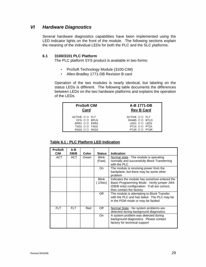
6.1 3100/3101 PLC PlatformThe PLC platform SYS product is available in two forms:
• ProSoft Technology Module (3100-CIM)• Allen-Bradley 1771-DB Revision B card
Operation of the two modules is nearly identical, but labeling on thestatus LEDs is different. The following table documents the differencesbetween LEDs on the two hardware platforms and explains the operationof the LEDs.
ProSoft CIM A-B 1771-DBCard Rev B Card
ACTIVE ¡ ¡ FLT ACTIVE ¡ ¡ FLTCFG ¡ ¡ BPLN DH485 ¡ ¡ BTLO
ERR1 ¡ ¡ ERR2 LED1 ¡ ¡ LED2TXD1 ¡ ¡ TXD2 PT1X ¡ ¡ PT2XRXD2 ¡ ¡ RXD2 PT1R ¡ ¡ PT2R
Table 6.1 : PLC Platform LED Indication
ProSoftCIM
A-BDB/B Color Status Indication
ACT ACT Green Blink(Fast)
Normal state : The module is operatingnormally and successfully Block Transferringwith the PLC
On The module is receiving power from thebackplane, but there may be some otherproblem
Blink( 1/Sec)
Indicates the module has somehow entered theBasic Programming Mode. Verify jumper JW4(DB/B only) configuration. If all are correct,then contact the factory
Off The module is attempting to Block Transferwith the PLC and has failed. The PLC may bein the PGM mode or may be faulted
FLT FLT Red Off Normal State : No system problems aredetected during background diagnostics
On A system problem was detected duringbackground diagnostics. Please contactfactory for technical support

30 Revised 06/26/98
Table 6.1 : PLC Platform LED Indication (Cont’d)
ProSoftName
DBName Color Status Indication
CFG DH485 Green Off Normal state : No configuration related activityis occurring at this time
Blink This light blinks every time a ModuleConfiguration block (ID = 255) is received fromthe processor ladder logic
On The light is on continuously whenever aconfiguration error is detected. The error couldbe in the Port Configuration data or in theSystem Configuration data. See Section 4 fordetails
BPLN BTLO Red Off Normal State : When this light is off and theACT light is blinking quickly, the module isactively Block Transferring data with the PLC
On Indicates that Block Transfers between the PLCand the module have failed.( Not activated inthe initial release of the product)
ERR1ERR2
LED1LED2
Amber Off Normal State : When the error LED is off andthe related port is actively transferring data,there are no communication errors
Blink Periodic communication errors are occurringduring data communications. See Section 4 todetermine the error condition
On This LED will stay on under several conditions:• CTS input is not being satisfied• Port Configuration Error• System Configuration Error• Unsuccessful comm on MCM slave• Recurring error condition on MCM master
Tx1Tx2
PT1XPT2X
Green Blink The port is transmitting data.
Rx1Rx2
PT1RPT2R
Green Blink The port is receiving data
6.2 3150/3151 SLC PlatformThe PLC platform SYS product is available in two forms:
• ProSoft Technology Module (3150-CIM)• Allen-Bradley 1746-BAS card
Operation of the two modules is nearly identical and labeling on thestatus LEDs is the same. The following table documents the differences

Revised 06/26/98 31
between LEDs on the two hardware platforms and explains the operationof the LEDs.
3150-SYS
COMMUNICATIONS
ACT
CFG
PRT1
PRT2
FAULT
BPLN
ERR1
ERR2
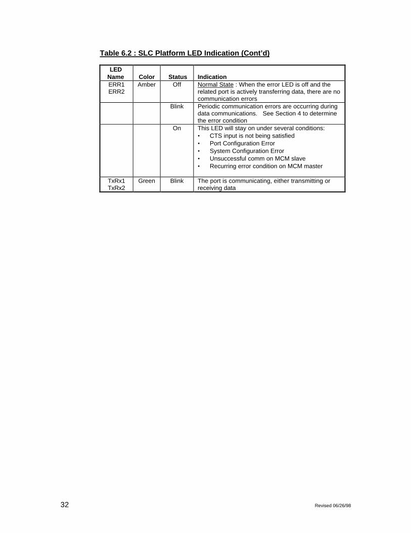
Table 6.2 : SLC Platform LED Indication
LEDName Color Status Indication ACT Green Blink
(Fast)Normal state : The module is operating normallyand successfully Block Transferring with the SLC
On The module is receiving power from the backplane,but there may be some other problem
Blink( 1/Sec)
Indicates the module has somehow entered theBasic Programming Mode. Verify jumper JW3 (BASonly) configuration. If all are correct, then contactthe factory
Off The module is attempting to Block Transfer with theSLC and has failed. The SLC may be in the PGMmode or may be faulted (Not in initial release)
FLT Red Off Normal State : No system problems are detectedduring background diagnostics
On A system problem was detected during backgrounddiagnostics. Please contact factory for technicalsupport
CFG Green Off Normal state : No configuration related activity isoccurring at this time
Blink This light blinks every time a Module Configurationblock (ID = 255) is received from the processorladder logic
On The light is on continuously whenever aconfiguration error is detected. The error could be inthe Port Configuration data or in the SystemConfiguration data. See Section 4 for details
BPLN Red Off Normal State : When this light is off and the ACTlight is blinking quickly, the module is actively BlockTransferring data with the SLC
On Indicates that Block Transfers between the SLC andthe module have failed
32 Revised 06/26/98
Table 6.2 : SLC Platform LED Indication (Cont’d)
LEDName Color Status IndicationERR1ERR2
Amber Off Normal State : When the error LED is off and therelated port is actively transferring data, there are nocommunication errors
Blink Periodic communication errors are occurring duringdata communications. See Section 4 to determinethe error condition
On This LED will stay on under several conditions:• CTS input is not being satisfied• Port Configuration Error• System Configuration Error• Unsuccessful comm on MCM slave• Recurring error condition on MCM master
TxRx1TxRx2
Green Blink The port is communicating, either transmitting orreceiving data

Revised 06/26/98 33
VII Support, Service and Warranty
7.1 Technical SupportProSoft Technology survives on its ability to provide meaningful supportto its customers. Should any questions or problems arise, please feelfree to contact us at:
ProSoft Technology, Inc.9801 Camino MediaSuite 105 Bakersfield, CA 93311(805) 664-7208(800) 326-7066(805) 664-7233 (fax)E-Mail : [email protected]
Before calling for support, please prepare yourself for the call. In orderto provide the best and quickest support possible, we will most likely askfor the following information (you may wish to fax it to us prior to calling):
1. Product Serial and Version Number2. Configuration Information
- Communication Configuration- Master Command List- Jumper positions
3. System hierachy4. Physical connection information
- RS-232, 422 or 485- Cable configuration
5. Module Operation- Block Transfers operation- LED patterns
An after-hours answering service (on the Bakersfield number) can patchyou to one our qualified technical and/or application support engineers atany time to answer the questions that are important to you.
7.2 Service and RepairThe ProSoft card is an electronic product, designed and manufactured tofunction under somewhat adverse conditions. As with any product,through age, misapplication, or any one of many possible problems, thecard may require repair.
The ProSoft product has a one year parts and labor warranty accordingto the limits specified in the warranty. Replacement and/or returns
34 Revised 06/26/98
should be directed to the distributor from whom the product waspurchased. If you need to return the card for repair, it is first necessaryto obtain an RMA number from ProSoft Technology. Please call thefactory for this number and display the number prominently on theoutside of the shipping carton used to return the card.
7.3 Warranty
7.3.1 General Warranty PolicyProSoft Technology, Inc. (Hereinafter referred to as ProSoft) warrants that theProduct shall conform to and perform in accordance with published technicalspecifications and the accompanying written materials, and shall be free ofdefects in materials and workmanship, for the period of time herein indicated,such warranty period commencing upon receipt of the Product.
This warranty is limited to the repair and/or replacement, at ProSoft's election,of defective or non-conforming Product, and ProSoft shall not be responsible forthe failure of the Product to perform specified functions, or any other non-conformance caused by or attributable to: (a) any misapplication of misuse ofthe Product; (b) failure of Customer to adhere to any of ProSoft's specificationsor instructions; (c) neglect of, abuse of, or accident to, the Product; or (d) anyassociated or complementary equipment or software not furnished by ProSoft.
Limited warranty service may be obtained by delivering the Product to ProSoftand providing proof of purchase or receipt date. Customer agrees to insure theProduct or assume the risk of loss or damage in transit, to prepay shippingcharges to ProSoft, and to use the original shipping container or equivalent.Contact ProSoft Customer Service for further information.
7.3.2 Limitation of LiabilityEXCEPT AS EXPRESSLY PROVIDED HEREIN, PROSOFT MAKES NOWARRANT OF ANY KIND, EXPRESSED OR IMPLIED, WITH RESPECT TOANY EQUIPMENT, PARTS OR SERVICES PROVIDED PURSUANT TO THISAGREEMENT, INCLUDING BUT NOT LIMITED TO THE IMPLIEDWARRANTIES OF MERCHANT ABILITY AND FITNESS FOR A PARTICULARPURPOSE. NEITHER PROSOFT OR ITS DEALER SHALL BE LIABLE FORANY OTHER DAMAGES, INCLUDING BUT NOT LIMITED TO DIRECT,INDIRECT, INCIDENTAL, SPECIAL OR CONSEQUENTIAL DAMAGES,WHETHER IN AN ACTION IN CONTRACT OR TORT (INCLUDINGNEGLIGENCE AND STRICT LIABILITY), SUCH AS, BUT NOT LIMITED TO,LOSS OF ANTICIPATED PROFITS OR BENEFITS RESULTING FROM, ORARISING OUT OF, OR IN CONNECTION WITH THE USE OR FURNISHINGOF EQUIPMENT, PARTS OR SERVICES HEREUNDER OR THEPERFORMANCE, USE OR INABILITY TO USE THE SAME, EVEN IFPROSOFT OR ITS DEALER'S TOTAL LIABILITY EXCEED THE PRICE PAIDFOR THE PRODUCT.
Where directed by State Law, some of the above exclusions or limitations maynot be applicable in some states. This warranty provides specific legal rights;other rights that vary from state to state may also exist. This warranty shall notbe applicable to the extent that any provisions of this warranty is prohibited byany Federal, State or Municipal Law that cannot be preempted.
7.3.3 Hardware Product Warranty DetailsWarranty Period : ProSoft warranties hardware product for a period of one (1)year.
Warranty Procedure : Upon return of the hardware Product ProSoft will, at itsoption, repair or replace Product at no additional charge, freight prepaid, except

Revised 06/26/98 35
as set forth below. Repair parts and replacement Product will be furnished onan exchange basis and will be either reconditioned or new. All replaced Productand parts become the property of ProSoft. If ProSoft determines that theProduct is not under warranty, it will, at the Customer's option, repair theProduct using current ProSoft standard rates for parts and labor, and return theProduct freight collect.

36 Revised 06/26/98
(This page intentionally left blank)

APPENDIX A-1
PLC-5 Example Ladder Logic
APPENDIX A-2
SLC-5/02 Example Ladder Logic


APPENDIX B
CABLE DIAGRAMS
RS-232-
RS-422-
RS-485
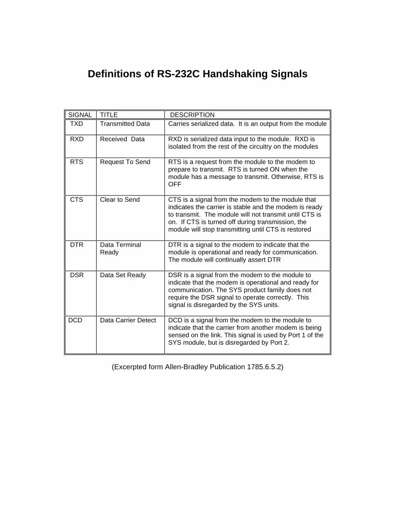
Definitions of RS-232C Handshaking Signals
SIGNAL TITLE DESCRIPTION TXD Transmitted Data Carries serialized data. It is an output from the module
RXD Received Data RXD is serialized data input to the module. RXD isisolated from the rest of the circuitry on the modules
RTS Request To Send RTS is a request from the module to the modem toprepare to transmit. RTS is turned ON when themodule has a message to transmit. Otherwise, RTS isOFF
CTS Clear to Send CTS is a signal from the modem to the module thatindicates the carrier is stable and the modem is readyto transmit. The module will not transmit until CTS ison. If CTS is turned off during transmission, themodule will stop transmitting until CTS is restored
DTR Data TerminalReady
DTR is a signal to the modem to indicate that themodule is operational and ready for communication.The module will continually assert DTR
DSR Data Set Ready DSR is a signal from the modem to the module toindicate that the modem is operational and ready forcommunication. The SYS product family does notrequire the DSR signal to operate correctly. Thissignal is disregarded by the SYS units.
DCD Data Carrier Detect DCD is a signal from the modem to the module toindicate that the carrier from another modem is beingsensed on the link. This signal is used by Port 1 of theSYS module, but is disregarded by Port 2.
(Excerpted form Allen-Bradley Publication 1785.6.5.2)
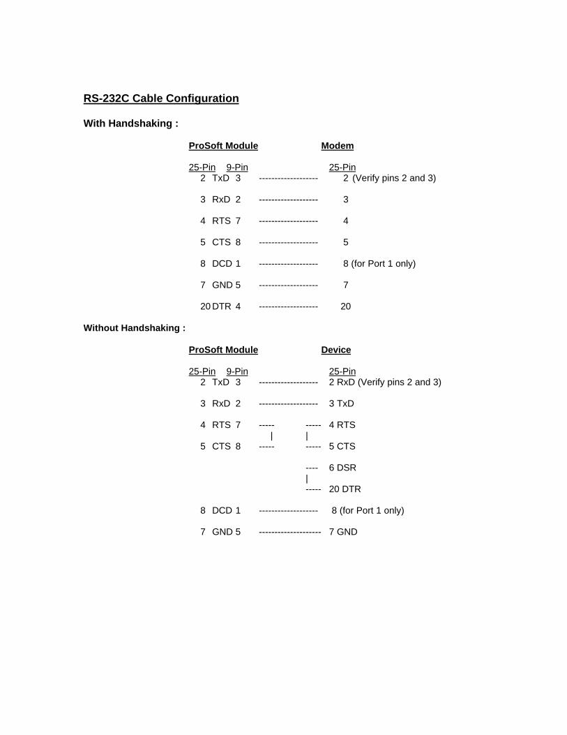
RS-232C Cable Configuration
With Handshaking :
ProSoft Module Modem
25-Pin 9-Pin 25-Pin2 TxD 3 ------------------- 2 (Verify pins 2 and 3)
3 RxD 2 ------------------- 3
4 RTS 7 ------------------- 4
5 CTS 8 ------------------- 5
8 DCD 1 ------------------- 8 (for Port 1 only)
7 GND 5 ------------------- 7
20 DTR 4 ------------------- 20
Without Handshaking :
ProSoft Module Device
25-Pin 9-Pin 25-Pin2 TxD 3 ------------------- 2 RxD (Verify pins 2 and 3)
3 RxD 2 ------------------- 3 TxD
4 RTS 7 ----- ----- 4 RTS| |
5 CTS 8 ----- ----- 5 CTS
---- 6 DSR |
----- 20 DTR
8 DCD 1 ------------------- 8 (for Port 1 only)
7 GND 5 -------------------- 7 GND

B-3

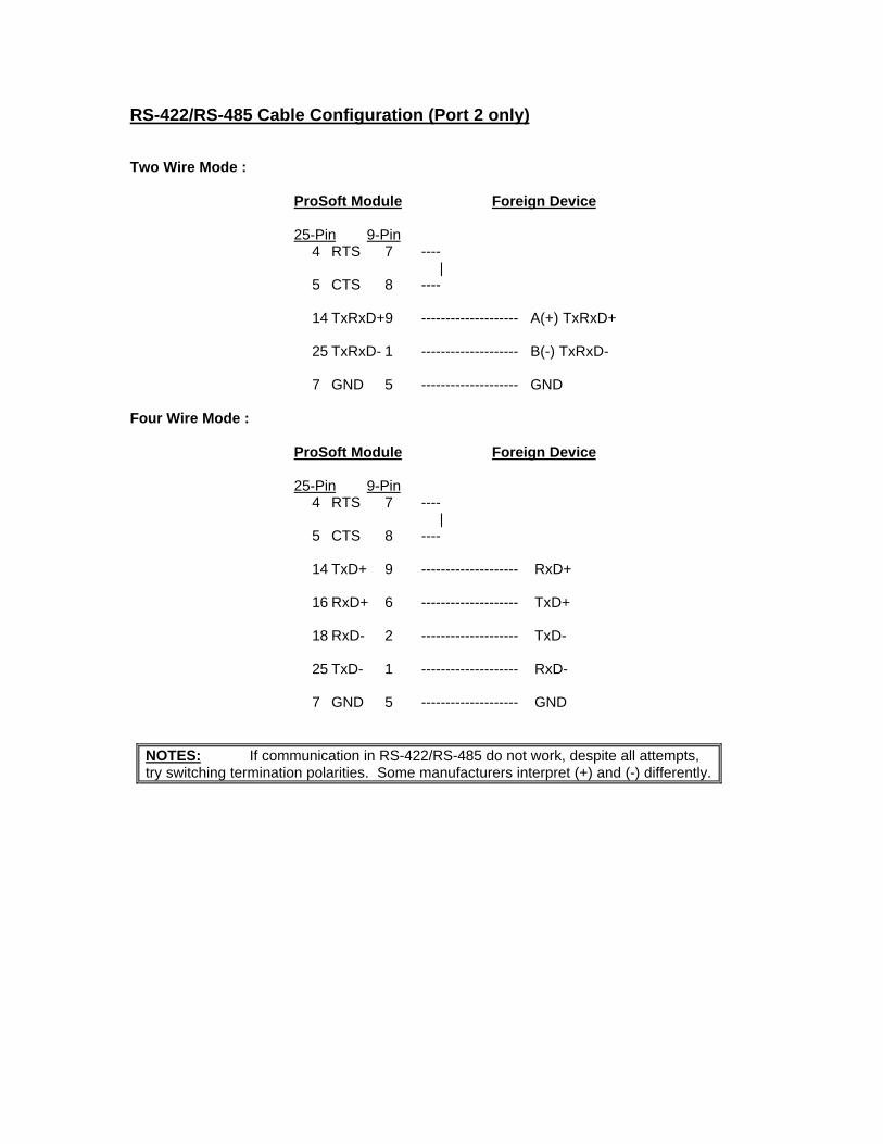
RS-422/RS-485 Cable Configuration (Port 2 only)
Two Wire Mode :
ProSoft Module Foreign Device
25-Pin 9-Pin4 RTS 7 ----
|5 CTS 8 ----
14 TxRxD+9 -------------------- A(+) TxRxD+
25 TxRxD- 1 -------------------- B(-) TxRxD-
7 GND 5 -------------------- GND
Four Wire Mode :
ProSoft Module Foreign Device
25-Pin 9-Pin4 RTS 7 ----
|5 CTS 8 ----
14 TxD+ 9 -------------------- RxD+
16 RxD+ 6 -------------------- TxD+
18 RxD- 2 -------------------- TxD-
25 TxD- 1 -------------------- RxD-
7 GND 5 -------------------- GND
NOTES: If communication in RS-422/RS-485 do not work, despite all attempts,try switching termination polarities. Some manufacturers interpret (+) and (-) differently.

APPENDIX C
Jumper Configurations
1771 Platform- 3100 Module- 1771-DB Revision B Module
1746 Platform- 3150 Module- 1746-BAS Module

3100 Module from ProSoft TechnologyThe 3100 module from ProSoft Technology is shipped from the factory as a completeunit including any applicable firmware resident in the module.
All jumper configurations have been preset for the module to pass a functional test atthe factory. Verify jumper placement with Section 2 of the manual for applicationspecific changes.

1771-DB Revision B Module from Allen-BradleyThe 3101 firmware solution is installed into an Allen-Bradley 1771-DB Revision Bmodule. To successfully operate the module, the firmware must be installed and thejumpers must be configured.
Section 2 of the manual details the correct positioning for the jumpers.
In addition, Section 2 also details the steps necessary to install the firmware chip. TheProSoft Technology firmware is shipped in a plastic carrier to help minimize erroneousinstallations.
The following diagrams help to identify the physical location of the jumpers on themodule and location of the firmware socket.
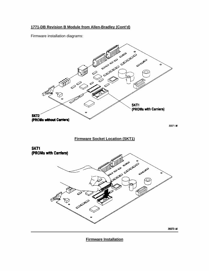
1771-DB Revision B Module from Allen-Bradley (Cont’d)
Firmware installation diagrams:
Firmware Socket Location (SKT1)
Firmware Installation
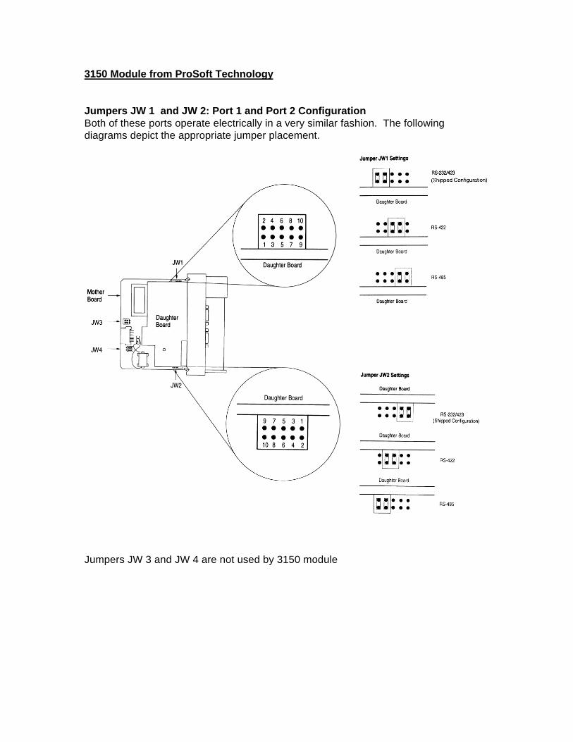
3150 Module from ProSoft Technology
Jumpers JW 1 and JW 2: Port 1 and Port 2 ConfigurationBoth of these ports operate electrically in a very similar fashion. The followingdiagrams depict the appropriate jumper placement.
Jumpers JW 3 and JW 4 are not used by 3150 module

1746-BAS Module from Allen-Bradley
Jumpers JW 1 and JW 2: Port 1 and Port 2 ConfigurationBoth of these ports operate electrically in a very similar fashion. The followingdiagrams depict the appropriate jumper placement.
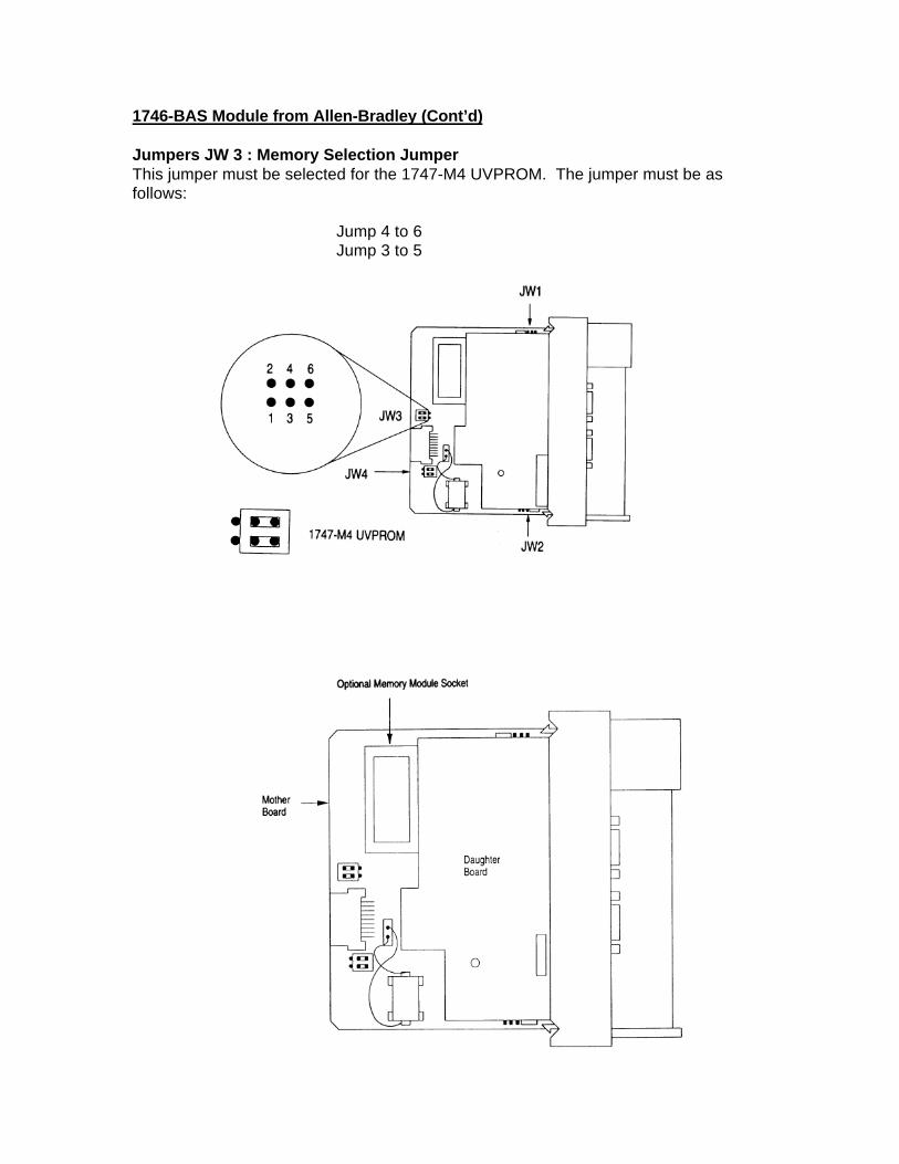
1746-BAS Module from Allen-Bradley (Cont’d)
Jumpers JW 3 : Memory Selection JumperThis jumper must be selected for the 1747-M4 UVPROM. The jumper must be asfollows:
Jump 4 to 6Jump 3 to 5

1746-BAS Module from Allen-Bradley (Cont’d)
Jumpers JW 4 : Module Port ConfigurationThis jumper must be selected as follows:
Jump 2 to 4Jump 1 to 3


APPENDIX D
Product Revision History

(This page intentionally left blank)

Product Revision History
07/11/95 Revision 2.0Initial release of product with dual port capabilityAdded 4Bh support in this release of protocol driver also

(This page intentionally left blank)

APPENDIX E
Systronics ProtocolCommand Structure
Function Code Description


![Quick3270 configuration file description - DN-Computing configuration.pdf · Quick3270 configuration file description 3/53 Configuration file sections or registry sub-key. [General]](https://static.fdocuments.us/doc/165x107/5c2d6ca109d3f2e90b8bae80/quick3270-configuration-file-description-dn-configurationpdf-quick3270-configuration.jpg)