
SYSMAC PROGRAMMABLE CONTROLLERS C200H (CPU01 … · SYSMAC Programmable Controllers C200H...
173
Cat. No. W111-E1-10 INSTALLATION GUIDE SYSMAC Programmable Controllers C200H (CPU01-E/03-E/11-E)
Transcript of SYSMAC PROGRAMMABLE CONTROLLERS C200H (CPU01 … · SYSMAC Programmable Controllers C200H...

Cat. No. W111-E1-10
INSTALLATION GUIDE
SYSMACProgrammable Controllers
C200H(CPU01-E/03-E/11-E)


C200H Programmable Controllers(CPU01-E/03-E/11-E)
Installation Guide
Revised January 2001

Terms and Conditions of Sale1. Offer; Acceptance. These terms and conditions (these "Terms") are deemed
part of all quotes, agreements, purchase orders, acknowledgments, price lists,catalogs, manuals, brochures and other documents, whether electronic or inwriting, relating to the sale of products or services (collectively, the "Products")by Omron Electronics LLC and its subsidiary companies (“Omron”). Omronobjects to any terms or conditions proposed in Buyer’s purchase order or otherdocuments which are inconsistent with, or in addition to, these Terms.
2. Prices; Payment Terms. All prices stated are current, subject to change with-out notice by Omron. Omron reserves the right to increase or decrease priceson any unshipped portions of outstanding orders. Payments for Products aredue net 30 days unless otherwise stated in the invoice.
3. Discounts. Cash discounts, if any, will apply only on the net amount of invoicessent to Buyer after deducting transportation charges, taxes and duties, and willbe allowed only if (i) the invoice is paid according to Omron’s payment termsand (ii) Buyer has no past due amounts.
4. Interest. Omron, at its option, may charge Buyer 1-1/2% interest per month orthe maximum legal rate, whichever is less, on any balance not paid within thestated terms.
5. Orders. Omron will accept no order less than $200 net billing. 6. Governmental Approvals. Buyer shall be responsible for, and shall bear all
costs involved in, obtaining any government approvals required for the impor-tation or sale of the Products.
7. Taxes. All taxes, duties and other governmental charges (other than generalreal property and income taxes), including any interest or penalties thereon,imposed directly or indirectly on Omron or required to be collected directly orindirectly by Omron for the manufacture, production, sale, delivery, importa-tion, consumption or use of the Products sold hereunder (including customsduties and sales, excise, use, turnover and license taxes) shall be charged toand remitted by Buyer to Omron.
8. Financial. If the financial position of Buyer at any time becomes unsatisfactoryto Omron, Omron reserves the right to stop shipments or require satisfactorysecurity or payment in advance. If Buyer fails to make payment or otherwisecomply with these Terms or any related agreement, Omron may (without liabil-ity and in addition to other remedies) cancel any unshipped portion of Prod-ucts sold hereunder and stop any Products in transit until Buyer pays allamounts, including amounts payable hereunder, whether or not then due,which are owing to it by Buyer. Buyer shall in any event remain liable for allunpaid accounts.
9. Cancellation; Etc. Orders are not subject to rescheduling or cancellationunless Buyer indemnifies Omron against all related costs or expenses.
10. Force Majeure. Omron shall not be liable for any delay or failure in deliveryresulting from causes beyond its control, including earthquakes, fires, floods,strikes or other labor disputes, shortage of labor or materials, accidents tomachinery, acts of sabotage, riots, delay in or lack of transportation or therequirements of any government authority.
11. Shipping; Delivery. Unless otherwise expressly agreed in writing by Omron:a. Shipments shall be by a carrier selected by Omron; Omron will not drop ship
except in “break down” situations.b. Such carrier shall act as the agent of Buyer and delivery to such carrier shall
constitute delivery to Buyer;c. All sales and shipments of Products shall be FOB shipping point (unless oth-
erwise stated in writing by Omron), at which point title and risk of loss shallpass from Omron to Buyer; provided that Omron shall retain a security inter-est in the Products until the full purchase price is paid;
d. Delivery and shipping dates are estimates only; ande. Omron will package Products as it deems proper for protection against nor-
mal handling and extra charges apply to special conditions.12. Claims. Any claim by Buyer against Omron for shortage or damage to the
Products occurring before delivery to the carrier must be presented in writingto Omron within 30 days of receipt of shipment and include the original trans-portation bill signed by the carrier noting that the carrier received the Productsfrom Omron in the condition claimed.
13. Warranties. (a) Exclusive Warranty. Omron’s exclusive warranty is that theProducts will be free from defects in materials and workmanship for a period oftwelve months from the date of sale by Omron (or such other period expressedin writing by Omron). Omron disclaims all other warranties, express or implied.(b) Limitations. OMRON MAKES NO WARRANTY OR REPRESENTATION,EXPRESS OR IMPLIED, ABOUT NON-INFRINGEMENT, MERCHANTABIL-
ITY OR FITNESS FOR A PARTICULAR PURPOSE OF THE PRODUCTS.BUYER ACKNOWLEDGES THAT IT ALONE HAS DETERMINED THAT THEPRODUCTS WILL SUITABLY MEET THE REQUIREMENTS OF THEIRINTENDED USE. Omron further disclaims all warranties and responsibility ofany type for claims or expenses based on infringement by the Products or oth-erwise of any intellectual property right. (c) Buyer Remedy. Omron’s sole obli-gation hereunder shall be, at Omron’s election, to (i) replace (in the formoriginally shipped with Buyer responsible for labor charges for removal orreplacement thereof) the non-complying Product, (ii) repair the non-complyingProduct, or (iii) repay or credit Buyer an amount equal to the purchase price ofthe non-complying Product; provided that in no event shall Omron be responsi-ble for warranty, repair, indemnity or any other claims or expenses regardingthe Products unless Omron’s analysis confirms that the Products were prop-erly handled, stored, installed and maintained and not subject to contamina-tion, abuse, misuse or inappropriate modification. Return of any Products byBuyer must be approved in writing by Omron before shipment. Omron Compa-nies shall not be liable for the suitability or unsuitability or the results from theuse of Products in combination with any electrical or electronic components,circuits, system assemblies or any other materials or substances or environ-ments. Any advice, recommendations or information given orally or in writing,are not to be construed as an amendment or addition to the above warranty.See http://oeweb.omron.com or contact your Omron representative for pub-lished information.
14. Limitation on Liability; Etc. OMRON COMPANIES SHALL NOT BE LIABLEFOR SPECIAL, INDIRECT, INCIDENTAL, OR CONSEQUENTIAL DAMAGES,LOSS OF PROFITS OR PRODUCTION OR COMMERCIAL LOSS IN ANYWAY CONNECTED WITH THE PRODUCTS, WHETHER SUCH CLAIM ISBASED IN CONTRACT, WARRANTY, NEGLIGENCE OR STRICT LIABILITY.Further, in no event shall liability of Omron Companies exceed the individualprice of the Product on which liability is asserted.
15. Indemnities. Buyer shall indemnify and hold harmless Omron Companies andtheir employees from and against all liabilities, losses, claims, costs andexpenses (including attorney's fees and expenses) related to any claim, inves-tigation, litigation or proceeding (whether or not Omron is a party) which arisesor is alleged to arise from Buyer's acts or omissions under these Terms or inany way with respect to the Products. Without limiting the foregoing, Buyer (atits own expense) shall indemnify and hold harmless Omron and defend or set-tle any action brought against such Companies to the extent based on a claimthat any Product made to Buyer specifications infringed intellectual propertyrights of another party.
16. Property; Confidentiality. Any intellectual property in the Products is the exclu-sive property of Omron Companies and Buyer shall not attempt to duplicate itin any way without the written permission of Omron. Notwithstanding anycharges to Buyer for engineering or tooling, all engineering and tooling shallremain the exclusive property of Omron. All information and materials suppliedby Omron to Buyer relating to the Products are confidential and proprietary,and Buyer shall limit distribution thereof to its trusted employees and strictlyprevent disclosure to any third party.
17. Export Controls. Buyer shall comply with all applicable laws, regulations andlicenses regarding (i) export of products or information; (iii) sale of products to“forbidden” or other proscribed persons; and (ii) disclosure to non-citizens ofregulated technology or information.
18. Miscellaneous. (a) Waiver. No failure or delay by Omron in exercising any rightand no course of dealing between Buyer and Omron shall operate as a waiverof rights by Omron. (b) Assignment. Buyer may not assign its rights hereunderwithout Omron's written consent. (c) Law. These Terms are governed by thelaw of the jurisdiction of the home office of the Omron company from whichBuyer is purchasing the Products (without regard to conflict of law princi-ples). (d) Amendment. These Terms constitute the entire agreement betweenBuyer and Omron relating to the Products, and no provision may be changedor waived unless in writing signed by the parties. (e) Severability. If any provi-sion hereof is rendered ineffective or invalid, such provision shall not invalidateany other provision. (f) Setoff. Buyer shall have no right to set off any amountsagainst the amount owing in respect of this invoice. (g) Definitions. As usedherein, “including” means “including without limitation”; and “Omron Compa-nies” (or similar words) mean Omron Corporation and any direct or indirectsubsidiary or affiliate thereof.
Certain Precautions on Specifications and Use1. Suitability of Use. Omron Companies shall not be responsible for conformity
with any standards, codes or regulations which apply to the combination of theProduct in the Buyer’s application or use of the Product. At Buyer’s request,Omron will provide applicable third party certification documents identifyingratings and limitations of use which apply to the Product. This information byitself is not sufficient for a complete determination of the suitability of the Prod-uct in combination with the end product, machine, system, or other applicationor use. Buyer shall be solely responsible for determining appropriateness ofthe particular Product with respect to Buyer’s application, product or system.Buyer shall take application responsibility in all cases but the following is anon-exhaustive list of applications for which particular attention must be given:(i) Outdoor use, uses involving potential chemical contamination or electricalinterference, or conditions or uses not described in this document.(ii) Use in consumer products or any use in significant quantities.(iii) Energy control systems, combustion systems, railroad systems, aviationsystems, medical equipment, amusement machines, vehicles, safety equip-ment, and installations subject to separate industry or government regulations.(iv) Systems, machines and equipment that could present a risk to life or prop-erty. Please know and observe all prohibitions of use applicable to this Prod-uct. NEVER USE THE PRODUCT FOR AN APPLICATION INVOLVING SERIOUSRISK TO LIFE OR PROPERTY OR IN LARGE QUANTITIES WITHOUTENSURING THAT THE SYSTEM AS A WHOLE HAS BEEN DESIGNED TO
ADDRESS THE RISKS, AND THAT THE OMRON’S PRODUCT IS PROP-ERLY RATED AND INSTALLED FOR THE INTENDED USE WITHIN THEOVERALL EQUIPMENT OR SYSTEM.
2. Programmable Products. Omron Companies shall not be responsible for theuser’s programming of a programmable Product, or any consequence thereof.
3. Performance Data. Data presented in Omron Company websites, catalogsand other materials is provided as a guide for the user in determining suitabil-ity and does not constitute a warranty. It may represent the result of Omron’stest conditions, and the user must correlate it to actual application require-ments. Actual performance is subject to the Omron’s Warranty and Limitationsof Liability.
4. Change in Specifications. Product specifications and accessories may bechanged at any time based on improvements and other reasons. It is our prac-tice to change part numbers when published ratings or features are changed,or when significant construction changes are made. However, some specifica-tions of the Product may be changed without any notice. When in doubt, spe-cial part numbers may be assigned to fix or establish key specifications foryour application. Please consult with your Omron’s representative at any timeto confirm actual specifications of purchased Product.
5. Errors and Omissions. Information presented by Omron Companies has beenchecked and is believed to be accurate; however, no responsibility is assumedfor clerical, typographical or proofreading errors or omissions.

!
!
!
v
Notice:OMRON products are manufactured for use according to proper procedures by a qualified operatorand only for the purposes described in this manual.
The following conventions are used to indicate and classify precautions in this manual. Always heedthe information provided with them. Failure to heed precautions can result in injury to people or dam-age to property.
DANGER Indicates an imminently hazardous situation which, if not avoided, will result in death orserious injury.
WARNING Indicates a potentially hazardous situation which, if not avoided, could result in death orserious injury.
Caution Indicates a potentially hazardous situation which, if not avoided, may result in minor ormoderate injury, or property damage.
OMRON Product ReferencesAll OMRON products are capitalized in this manual. The word “Unit” is also capitalized when it refersto an OMRON product, regardless of whether or not it appears in the proper name of the product.
The abbreviation “Ch,” which appears in some displays and on some OMRON products, often means“word” and is abbreviated “Wd” in documentation in this sense.
The abbreviation “PC” means Programmable Controller and is not used as an abbreviation for any-thing else.
Visual AidsThe following headings appear in the left column of the manual to help you locate different types ofinformation.
Note Indicates information of particular interest for efficient and convenient operationof the product.
1, 2, 3... 1. Indicates lists of one sort or another, such as procedures, checklists, etc.
© OMRON, 1990All rights reserved. No part of this publication may be reproduced, stored in a retrieval system, or transmitted, in anyform, or by any means, mechanical, electronic, photocopying, recording, or otherwise, without the prior written permis-sion of OMRON.
No patent liability is assumed with respect to the use of the information contained herein. Moreover, because OMRON isconstantly striving to improve its high-quality products, the information contained in this manual is subject to changewithout notice. Every precaution has been taken in the preparation of this manual. Nevertheless, OMRON assumes noresponsibility for errors or omissions. Neither is any liability assumed for damages resulting from the use of the informa-tion contained in this publication.

vi
TABLE OF CONTENTS
vii
PRECAUTIONS . . . . . . . . . . . . . . . . . . . . . . . . . . . . . . . . . 1 Intended Audience . . . . . . . . . . . . . . . . . . . . . . . . . . . . . . . . . . . . . . . . . . . . . . . . . . . . . . . . . . . 2 General Precautions . . . . . . . . . . . . . . . . . . . . . . . . . . . . . . . . . . . . . . . . . . . . . . . . . . . . . . . . . . 3 Safety Precautions . . . . . . . . . . . . . . . . . . . . . . . . . . . . . . . . . . . . . . . . . . . . . . . . . . . . . . . . . . . 4 Operating Environment Precautions . . . . . . . . . . . . . . . . . . . . . . . . . . . . . . . . . . . . . . . . . . . . . 5 Application Precautions . . . . . . . . . . . . . . . . . . . . . . . . . . . . . . . . . . . . . . . . . . . . . . . . . . . . . .
SECTION 1Introduction . . . . . . . . . . . . . . . . . . . . . . . . . . . . . . . . . . . .
1-1 What is a Control System? . . . . . . . . . . . . . . . . . . . . . . . . . . . . . . . . . . . . . . . . . . . . . . . . . 1-2 The Role of the PC . . . . . . . . . . . . . . . . . . . . . . . . . . . . . . . . . . . . . . . . . . . . . . . . . . . . . . . 1-3 How Does a PC Work? . . . . . . . . . . . . . . . . . . . . . . . . . . . . . . . . . . . . . . . . . . . . . . . . . . . .
SECTION 2Description . . . . . . . . . . . . . . . . . . . . . . . . . . . . . . . . . . . . .
2-1 CPU Rack . . . . . . . . . . . . . . . . . . . . . . . . . . . . . . . . . . . . . . . . . . . . . . . . . . . . . . . . . . . . . . 2-2 CPU . . . . . . . . . . . . . . . . . . . . . . . . . . . . . . . . . . . . . . . . . . . . . . . . . . . . . . . . . . . . . . . . . . 2-3 Expansion I/O Rack . . . . . . . . . . . . . . . . . . . . . . . . . . . . . . . . . . . . . . . . . . . . . . . . . . . . . . 2-4 Power Supply . . . . . . . . . . . . . . . . . . . . . . . . . . . . . . . . . . . . . . . . . . . . . . . . . . . . . . . . . . . 2-5 I/O Units . . . . . . . . . . . . . . . . . . . . . . . . . . . . . . . . . . . . . . . . . . . . . . . . . . . . . . . . . . . . . . . 2-6 Memory Units . . . . . . . . . . . . . . . . . . . . . . . . . . . . . . . . . . . . . . . . . . . . . . . . . . . . . . . . . . .
SECTION 3Assembly Instructions . . . . . . . . . . . . . . . . . . . . . . . . . . . .
3-1 Mounting the Units . . . . . . . . . . . . . . . . . . . . . . . . . . . . . . . . . . . . . . . . . . . . . . . . . . . . . . . 3-2 Memory Packs . . . . . . . . . . . . . . . . . . . . . . . . . . . . . . . . . . . . . . . . . . . . . . . . . . . . . . . . . . 3-3 System Configurations . . . . . . . . . . . . . . . . . . . . . . . . . . . . . . . . . . . . . . . . . . . . . . . . . . . .
SECTION 4System Connections . . . . . . . . . . . . . . . . . . . . . . . . . . . . . .
4-1 IR Word Allocation . . . . . . . . . . . . . . . . . . . . . . . . . . . . . . . . . . . . . . . . . . . . . . . . . . . . . . 4-2 Remote I/O . . . . . . . . . . . . . . . . . . . . . . . . . . . . . . . . . . . . . . . . . . . . . . . . . . . . . . . . . . . . . 4-3 Maximum Current and Power Supplied . . . . . . . . . . . . . . . . . . . . . . . . . . . . . . . . . . . . . . . 4-4 I/O Connections . . . . . . . . . . . . . . . . . . . . . . . . . . . . . . . . . . . . . . . . . . . . . . . . . . . . . . . . .
SECTION 5Installation Environment . . . . . . . . . . . . . . . . . . . . . . . . .
5-1 Installation Environment . . . . . . . . . . . . . . . . . . . . . . . . . . . . . . . . . . . . . . . . . . . . . . . . . . 5-2 Mounting Requirements . . . . . . . . . . . . . . . . . . . . . . . . . . . . . . . . . . . . . . . . . . . . . . . . . . . 5-3 Duct Work . . . . . . . . . . . . . . . . . . . . . . . . . . . . . . . . . . . . . . . . . . . . . . . . . . . . . . . . . . . . . 5-4 Preventing Noise . . . . . . . . . . . . . . . . . . . . . . . . . . . . . . . . . . . . . . . . . . . . . . . . . . . . . . . .
SECTION 6Power Considerations . . . . . . . . . . . . . . . . . . . . . . . . . . . .
6-1 Grounding . . . . . . . . . . . . . . . . . . . . . . . . . . . . . . . . . . . . . . . . . . . . . . . . . . . . . . . . . . . . . . 6-2 Insulation . . . . . . . . . . . . . . . . . . . . . . . . . . . . . . . . . . . . . . . . . . . . . . . . . . . . . . . . . . . . . . 6-3 Emergency Stop . . . . . . . . . . . . . . . . . . . . . . . . . . . . . . . . . . . . . . . . . . . . . . . . . . . . . . . . . 6-4 Wiring . . . . . . . . . . . . . . . . . . . . . . . . . . . . . . . . . . . . . . . . . . . . . . . . . . . . . . . . . . . . . . . . .
SECTION 7Safety Considerations . . . . . . . . . . . . . . . . . . . . . . . . . . . .
7-1 Interlock Circuits . . . . . . . . . . . . . . . . . . . . . . . . . . . . . . . . . . . . . . . . . . . . . . . . . . . . . . . . 7-2 Wiring . . . . . . . . . . . . . . . . . . . . . . . . . . . . . . . . . . . . . . . . . . . . . . . . . . . . . . . . . . . . . . . . .

TABLE OF CONTENTS
viii
AppendicesA Inspection and Maintenance . . . . . . . . . . . . . . . . . . . . . . . . . . . . . . . . . . . . . . . . . . . . . . . . . . B Specifications . . . . . . . . . . . . . . . . . . . . . . . . . . . . . . . . . . . . . . . . . . . . . . . . . . . . . . . . . . . . . . C Standard Models . . . . . . . . . . . . . . . . . . . . . . . . . . . . . . . . . . . . . . . . . . . . . . . . . . . . . . . . . . . D Programming Console Operation . . . . . . . . . . . . . . . . . . . . . . . . . . . . . . . . . . . . . . . . . . . . . . E Programming Instructions . . . . . . . . . . . . . . . . . . . . . . . . . . . . . . . . . . . . . . . . . . . . . . . . . . . .
Glossary . . . . . . . . . . . . . . . . . . . . . . . . . . . . . . . . . . . . . . . Index . . . . . . . . . . . . . . . . . . . . . . . . . . . . . . . . . . . . . . . . . . Revision History . . . . . . . . . . . . . . . . . . . . . . . . . . . . . . . . .

ix
About this Manual:
This manual explains how to install a C-series C200H Programmable Controller(CPU01-E/03-E/11-E).
Section 1 is an introduction to Programmable Controllers. General information about what a Programma-ble Controller can do and how a Programmable Controller works is provided.
Section 2 provides a description of all the components of the C200H. The names of all the individual partsof each Unit are given.
Section 3 explains how to assemble the C200H. A detailed description of how to mount each Unit is pro-vided.
Section 4 outlines the system connections involved in installing a C200H Programmable Controller Sys-tem. All I/O, including Remote I/O, are included.
Section 5 contains the requirements for the installation environment of the C200H. Suggestions for pre-venting electrical noise are included.
Section 6 explains the power considerations involved in installing the C200H.
Section 7 lists safety considerations that should be kept in mind while installing the C200H.
Appendixes, a Glossary, and an Index are also provided.
WARNING Failure to read and understand the information provided in this manual may result inpersonal injury or death, damage to the product, or product failure. Please read eachsection in its entirety and be sure you understand the information provided in the sectionand related sections before attempting any of the procedures or operations given.
!


xi
PRECAUTIONS
This section provides general precautions for using the Programmable Controller (PC) and related devices.
The information contained in this section is important for the safe and reliable application of the Programmable Con-troller. You must read this section and understand the information contained before attempting to set up or operate aPC system.
1 Intended Audience . . . . . . . . . . . . . . . . . . . . . . . . . . . . . . . . . . . . . . . . . . . . . . . . . . . . . . . . . . . . 2 General Precautions . . . . . . . . . . . . . . . . . . . . . . . . . . . . . . . . . . . . . . . . . . . . . . . . . . . . . . . . . . . 3 Safety Precautions . . . . . . . . . . . . . . . . . . . . . . . . . . . . . . . . . . . . . . . . . . . . . . . . . . . . . . . . . . . . 4 Operating Environment Precautions . . . . . . . . . . . . . . . . . . . . . . . . . . . . . . . . . . . . . . . . . . . . . . 5 Application Precautions . . . . . . . . . . . . . . . . . . . . . . . . . . . . . . . . . . . . . . . . . . . . . . . . . . . . . . . .
!
!
!
!
!
3Safety Precautions
xii
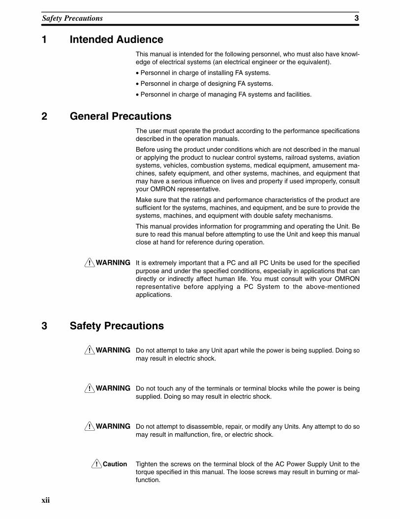
1 Intended AudienceThis manual is intended for the following personnel, who must also have knowl-edge of electrical systems (an electrical engineer or the equivalent).
• Personnel in charge of installing FA systems.
• Personnel in charge of designing FA systems.
• Personnel in charge of managing FA systems and facilities.
2 General PrecautionsThe user must operate the product according to the performance specificationsdescribed in the operation manuals.
Before using the product under conditions which are not described in the manualor applying the product to nuclear control systems, railroad systems, aviationsystems, vehicles, combustion systems, medical equipment, amusement ma-chines, safety equipment, and other systems, machines, and equipment thatmay have a serious influence on lives and property if used improperly, consultyour OMRON representative.
Make sure that the ratings and performance characteristics of the product aresufficient for the systems, machines, and equipment, and be sure to provide thesystems, machines, and equipment with double safety mechanisms.
This manual provides information for programming and operating the Unit. Besure to read this manual before attempting to use the Unit and keep this manualclose at hand for reference during operation.
WARNING It is extremely important that a PC and all PC Units be used for the specifiedpurpose and under the specified conditions, especially in applications that candirectly or indirectly affect human life. You must consult with your OMRONrepresentative before applying a PC System to the above-mentionedapplications.
3 Safety Precautions
WARNING Do not attempt to take any Unit apart while the power is being supplied. Doing somay result in electric shock.
WARNING Do not touch any of the terminals or terminal blocks while the power is beingsupplied. Doing so may result in electric shock.
WARNING Do not attempt to disassemble, repair, or modify any Units. Any attempt to do somay result in malfunction, fire, or electric shock.
Caution Tighten the screws on the terminal block of the AC Power Supply Unit to thetorque specified in this manual. The loose screws may result in burning or mal-function.

!
!
!
!
!
5Application Precautions
xiii
4 Operating Environment Precautions
Caution Do not operate the control system in the following places:
• Locations subject to direct sunlight.
• Locations subject to temperatures or humidity outside the range specified inthe specifications.
• Locations subject to condensation as the result of severe changes in tempera-ture.
• Locations subject to corrosive or flammable gases.
• Locations subject to dust (especially iron dust) or salts.
• Locations subject to exposure to water, oil, or chemicals.
• Locations subject to shock or vibration.
Caution Take appropriate and sufficient countermeasures when installing systems in thefollowing locations:
• Locations subject to static electricity or other forms of noise.
• Locations subject to strong electromagnetic fields.
• Locations subject to possible exposure to radioactivity.
• Locations close to power supplies.
Caution The operating environment of the PC System can have a large effect on the lon-gevity and reliability of the system. Improper operating environments can lead tomalfunction, failure, and other unforeseeable problems with the PC System. Besure that the operating environment is within the specified conditions at installa-tion and remains within the specified conditions during the life of the system.
5 Application PrecautionsObserve the following precautions when using the PC System.
WARNING Always heed these precautions. Failure to abide by the following precautionscould lead to serious or possibly fatal injury.
• Always ground the system to 100 Ω or less when installing the Units. Not con-necting to a ground of 100 Ω or less may result in electric shock.
• Always turn OFF the power supply to the PC before attempting any of the fol-lowing. Not turning OFF the power supply may result in malfunction or electricshock.
• Mounting or dismounting Power Supply Units, I/O Units, CPU Units,Memory Cassettes, or any other Units.
• Assembling the Units.
• Setting DIP switches or rotary switches.
• Connecting or wiring the cables.
• Connecting or disconnecting the connectors.
Caution Failure to abide by the following precautions could lead to faulty operation of thePC or the system, or could damage the PC or PC Units. Always heed these pre-cautions.
• Fail-safe measures must be taken by the customer to ensure safety in theevent of incorrect, missing, or abnormal signals caused by broken signal lines,momentary power interruptions, or other causes.
5Application Precautions
xiv
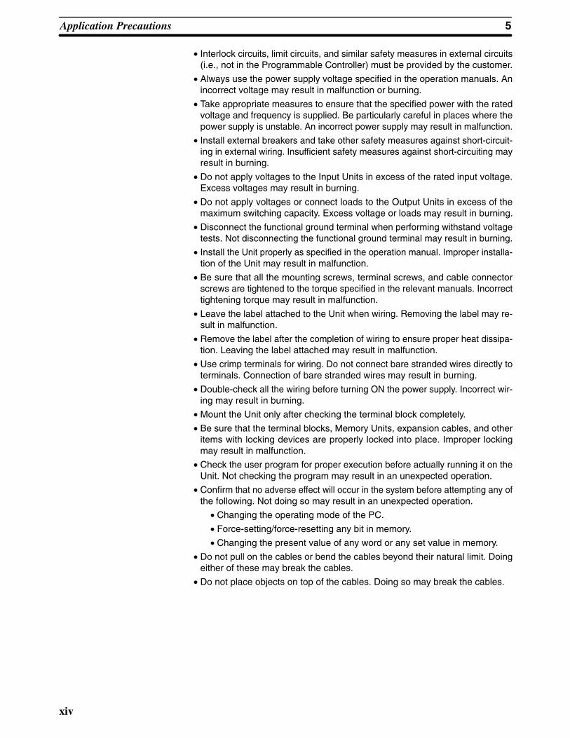
• Interlock circuits, limit circuits, and similar safety measures in external circuits(i.e., not in the Programmable Controller) must be provided by the customer.
• Always use the power supply voltage specified in the operation manuals. Anincorrect voltage may result in malfunction or burning.
• Take appropriate measures to ensure that the specified power with the ratedvoltage and frequency is supplied. Be particularly careful in places where thepower supply is unstable. An incorrect power supply may result in malfunction.
• Install external breakers and take other safety measures against short-circuit-ing in external wiring. Insufficient safety measures against short-circuiting mayresult in burning.
• Do not apply voltages to the Input Units in excess of the rated input voltage.Excess voltages may result in burning.
• Do not apply voltages or connect loads to the Output Units in excess of themaximum switching capacity. Excess voltage or loads may result in burning.
• Disconnect the functional ground terminal when performing withstand voltagetests. Not disconnecting the functional ground terminal may result in burning.
• Install the Unit properly as specified in the operation manual. Improper installa-tion of the Unit may result in malfunction.
• Be sure that all the mounting screws, terminal screws, and cable connectorscrews are tightened to the torque specified in the relevant manuals. Incorrecttightening torque may result in malfunction.
• Leave the label attached to the Unit when wiring. Removing the label may re-sult in malfunction.
• Remove the label after the completion of wiring to ensure proper heat dissipa-tion. Leaving the label attached may result in malfunction.
• Use crimp terminals for wiring. Do not connect bare stranded wires directly toterminals. Connection of bare stranded wires may result in burning.
• Double-check all the wiring before turning ON the power supply. Incorrect wir-ing may result in burning.
• Mount the Unit only after checking the terminal block completely.
• Be sure that the terminal blocks, Memory Units, expansion cables, and otheritems with locking devices are properly locked into place. Improper lockingmay result in malfunction.
• Check the user program for proper execution before actually running it on theUnit. Not checking the program may result in an unexpected operation.
• Confirm that no adverse effect will occur in the system before attempting any ofthe following. Not doing so may result in an unexpected operation.
• Changing the operating mode of the PC.
• Force-setting/force-resetting any bit in memory.
• Changing the present value of any word or any set value in memory.
• Do not pull on the cables or bend the cables beyond their natural limit. Doingeither of these may break the cables.
• Do not place objects on top of the cables. Doing so may break the cables.

1
SECTION 1Introduction
This section provides general information about Programmable Controllers (PCs) and how they fit into a Control System.
1-1 What is a Control System? . . . . . . . . . . . . . . . . . . . . . . . . . . . . . . . . . . . . . . . . . . . . . . . . . . 1-2 The Role of the PC . . . . . . . . . . . . . . . . . . . . . . . . . . . . . . . . . . . . . . . . . . . . . . . . . . . . . . . .
1-2-1 Input Devices . . . . . . . . . . . . . . . . . . . . . . . . . . . . . . . . . . . . . . . . . . . . . . . . . . . . . 1-2-2 Output Devices . . . . . . . . . . . . . . . . . . . . . . . . . . . . . . . . . . . . . . . . . . . . . . . . . . .
1-3 How Does a PC Work? . . . . . . . . . . . . . . . . . . . . . . . . . . . . . . . . . . . . . . . . . . . . . . . . . . . . .

1-1SectionWhat is a Control System?
2
1-1 What is a Control System?A Control System is the electronic equipment needed to control a particularprocess. It may include everything from a process control computer, if one isused, to the factory computer, down through the PCs (and there may be many ofthem networked together) and then on down through the network to the controlcomponents: the switches, stepping motors, solenoids, and sensors whichmonitor and control the mechanical operations.
PC PC PC
PCs
Process Control Computer
Factory Computer
Control Components
A Control System can involve very large applications where many different mod-els of PC are networked together or it could be an application as small as a singlePC controlling a single output device.

1-1SectionWhat is a Control System?
3
A Position Control System
Position Control Unit
Signal line forServomotordriver control
Hand-held ProgrammingConsole
Control switch
Control panel
Powersource
Powersource
DC Servomotor Driver
DC Servomotor
DC Servomotor
DC ServomotorDriver
PC
Input Unit
In the typical Control System example shown above, a PC controls the move-ment of the workpiece bed across two horizontal axes using Limit Switches andServomotors to monitor and control movement.

1-2SectionThe Role of the PC
4
1-2 The Role of the PCThe PC is the part of the Control System that directly controls the manufacturingprocess. According to the program stored in its memory, the PC accepts datafrom the input devices connected to it, and uses this data to monitor the con-trolled system. When the program calls for some action to take place, the PCsends data to the output devices connected to it, to cause that action to takeplace. The PC may be used to control a simple, repetitive task, or it may be con-nected to other PCs, or to a host computer in order to integrate the control of acomplex process.
1-2-1 Input DevicesPCs can receive input from either automated or manual devices. The PC couldreceive data from the user via a pushbutton switch, keyboard, or similar device.Automated input could come from a variety of devices: microswitches, timers,encoders, photosensors, and so on. Some devices, like the Limit Switch shownbelow, turn ON or OFF when the equipment actually makes contact with it. Otherdevices, like the Photoelectric Switch and Proximity Switch shown below, useother means, such as light or inductance, in order to get information about theequipment being monitored.
Photoelectric Switch Limit Switch
Proximity Switch

1-2SectionThe Role of the PC
5
1-2-2 Output DevicesA PC can output to a myriad of devices for use in automated control. Almost any-thing that you can think of could be controlled (perhaps indirectly) by a PC. Someof the most common devices are motors, Solenoids, Servomotors, SteppingMotors, valves, switches, indicator lights, buzzers, and alarms. Some of theseoutput devices; such as the motors, Solenoids, Servomotors, Stepping Motors,and valves; affect the controlled system directly. Others; such as the indicatorlights, buzzers, and alarms; provide output to notify personnel.
SolenoidServomotor
Stepping Motor

1-3SectionHow Does a PC Work?
6
1-3 How Does a PC Work?PCs operate by monitoring input signals and providing output signals. Whenchanges are detected in the signals, the PC reacts, through the user-pro-grammed internal logic, to produce output signals. The PC continually cycles theprogram in its memory to achieve this control.
Block Diagram of PC
Power Supply
Input OutputCPU
Memory
ProgrammingDevice
Signalsfromswitches,sensors,etc.
Signals toSolenoids,motors,etc.
A program for your applications must be designed, and stored in the PC. Thisprogram is then executed as part of the cycle of internal operations of the PC.
CycleWhen a PC operates, that is, when it executes its program to control an externalsystem, a series of operations are performed inside the PC. These internal op-erations can be broadly classified into the following four categories:
1, 2, 3... 1. Common (or overseeing) processes, such as watchdog timer operation andtesting the program memory.
2. Data input and output.
3. Instruction execution.
4. Peripheral device servicing.
Cycle TimeThe total time required for a PC to perform all these internal operations is calledthe cycle time. The flowchart and diagram on the following page illustrate theseinternal operations for a typical PC.
Timing is one of the most important factors in designing a Control System. Foraccurate operations, it is necessary to have answers to such questions as these:
• How long does it take for the PC to execute all the instructions in its memory?
• How long does it take for the PC to produce a control output in response to agiven input signal?
The cycle time of the PC can be automatically calculated and monitored, but it isnecessary to have an understanding of the timing relationships within the PC foreffective System design and programming.

1-3SectionHow Does a PC Work?
7
PC Operation Flowchart
Check OK?
Services peripherals
Power application
No
Yes
Checks I/O Units
Resets watchdog timer
Clears data areas andresets System counters
Checks hardware andprogram memory
Sets error flag andlights indicator
Error or alarm?
Error
Alarm
PCcycletime
Initialprocessingon powerapplication
Commonprocesses
Servic-ingperiph-eraldevices
Instructionexecution
Inputrefreshing
IR data to Output Units Resets watchdog timerand program counter
Proceses remote I/O
Resets watchdog timer
Resets watchdog timer
End of program?No
Yes
Input Unit data to IR area
Executes program
End of program?No
Yes
Remoteproces-sing
Outputrefresh-ing


9
SECTION 2Description
This section provides information about the individual Units that make up a PC. The names of all the parts of a Unit are given,followed by any details that apply to that Unit alone. For a description of how the Units fit together to become a PC, refer toSection 3 Assembly Instructions. For information about the model numbers of any of the parts described in this section, refer toAppendix C Standard Models.
2-1 CPU Rack . . . . . . . . . . . . . . . . . . . . . . . . . . . . . . . . . . . . . . . . . . . . . . . . . . . . . . . . . . . . . . . 2-2 CPU . . . . . . . . . . . . . . . . . . . . . . . . . . . . . . . . . . . . . . . . . . . . . . . . . . . . . . . . . . . . . . . . . . . 2-3 Expansion I/O Rack . . . . . . . . . . . . . . . . . . . . . . . . . . . . . . . . . . . . . . . . . . . . . . . . . . . . . . . 2-4 Power Supply . . . . . . . . . . . . . . . . . . . . . . . . . . . . . . . . . . . . . . . . . . . . . . . . . . . . . . . . . . . . 2-5 I/O Units . . . . . . . . . . . . . . . . . . . . . . . . . . . . . . . . . . . . . . . . . . . . . . . . . . . . . . . . . . . . . . . .2-6 Memory Units . . . . . . . . . . . . . . . . . . . . . . . . . . . . . . . . . . . . . . . . . . . . . . . . . . . . . . . . . . .

2-1SectionCPU Rack
10
2-1 CPU RackThe following figure shows the names of all the parts of a CPU Rack. There arefour models of Backplanes available with 3, 5, 8 and 10 slots for I/O Units. Youcan use any of these Backplanes to build a CPU or Expansion I/O Rack. Howev-er, the C200H-OC225/OD212/OD21A 16-point Output Unit and C200H-B7AO1B7A Interface Unit must be mounted to a C200H-BC��1-V1/V2 Backplane.
Backplane mountingscrews (four, with4-mm dia. heads)
CPUI/O Units
I/O Connecting Cable connectorConnects CPU Rack to Expansion I/O RackWhen not used, cover with a cap.
This connector not used:Cover with a cap.
Backplane

2-2SectionCPU
11
2-2 CPU
The CPU is available in three models. The C200H-CPU01-E and C200H-CPU11-E both run on 100 to 120 or 200 to 240 VAC, and the C200H-CPU03-Eruns on 24 VDC. The C200H-CPU11-E is unique in that it connects the SYSMACLINK Unit or SYSMAC NET Link Unit to the CPU. These two Units are mountedto either of the two slots located directly to the left of the the CPU and connectedto the CPU via a bus connector. A separate Unit, the Bus Connector Unit, is re-quired to connect the SYSMAC NET Link Unit or the SYSMAC LINK Unit to theCPU.
Also note that model C200H-CPU11-E has an additional battery connected tothe CPU.
Note If you are using the SYSMAC LINK Unit or SYSMAC NET Link Unit in yourC200H system, use model C200H-CPU11-E as the CPU. Otherwise, the linkUnits cannot be used.
C200H-CPU01-E/03
Power fuseIndicators
Detachableterminal block
Peripheral devicemounting hole
Handheld Programming Console connector Remove cover to gain access to connector.
Programming Console connector(Peripheral device connector)Remove cover to gain access to connector; store cov-er in cover storage slot.
Programming Consoleconnector cover storage slot
Memory Packconnector

2-2SectionCPU
12
C200H-CPU11-E
MemoryPackconnector
Bus connectorAvailable only with theC200H-CPU11-E.Used to connect thisUnit to a SYSMACLINK Unit or SYSMACNET Link Unit.
Programming Con-sole connector cov-er storage slot
Indicators
Programming Console connector(Peripheral device connector)
Power fuseMF51NR (5.2 dia. x 20mm) 2A 250 V
Battery compart-ment
Handheld Program-ming Console con-nector
The following figure shows the indicators that are located on the front panel ofthe three CPU models.
RUN indicator (green)Lights when the PC isoperating normally.
POWER (green)Lights when power issupplied to the CPU.
OUT INHIBIT (red)Lights when the Load OFFflag (SR bit 25215) turns ON,at which time all the outputsare turned OFF.
ALARM (blinking red)Blinks if an error occurs thatdoes not stop the CPU.
ERROR (solid red)Lights if an error occurs that stops theCPU, at which time the RUN indicatorturns OFF and the outputs are turnedOFF.
CPU Indicators

2-2SectionCPU
13
All three CPU models are equipped with two connectors for peripheral devices.One is used for the Handheld Programming Console or the Data Access Con-sole; the other is used for the CPU-Mounting Programming Console. TheC200H-CPU11-E, however, has a third connector that is used for connecting theSYSMAC LINK Unit or the SYSMAC NET Link Unit to the CPU.
To connect the Handheld Programming Console to the CPU, a ConnectingCable is required, as shown in the following diagram.
Note If you are using the SYSMAC LINK Unit or SYSMAC NET Link Unit in your sys-tem, you must use model C200H-CPU11-E as the CPU. The other two modelsmentioned above are not equipped with the appropriate connectors.
Cable Connection
Connecting Cable
HandheldProgramming Console
The CPU-mounting Programming Console can be mounted directly to the CPUand does not require a Connecting Cable. To mount the CPU-Mounting Pro-gramming Console (or any other peripheral device) directly to the CPU, followthe steps below.
The CPU-mounting Programming Console, when mounted to the CPU, coversthe two I/O Units located directly to the left of the CPU. For this reason it is impor-tant to know which shapes can be mounted to these slots.
Notice, in the following diagram, that the two I/O Units mounted directly to the leftof the CPU are A-shape Units. The CPU-mounting Programming Console canbe mounted to the CPU provided A-shape I/O Units are mounted to these twoslots. Make sure the protective covers of the two I/O Units are in place to avoidelectrical interference with the CPU.
Because the surface of B-shape and E-shape I/O Units protrudes a few centime-ters from surface of the CPU, B-shape and E-shape I/O Units cannot bemounted to the two slots to the left of the CPU unless a Programming ConsoleBase Unit is first mounted to the CPU to increase the mounting height of the Pro-gramming Console.
Peripheral DeviceConnectors
Direct Mounting

2-2SectionCPU
14
If you are using the C200H-CPU11-E, a SYSMAC LINK Unit or a SYSMAC LINKUnit can be mounted to either of the two slots to the left of the CPU. They are thenconnected to the CPU with the Bus Connector Unit.
Peripheraldevice
CPU Rack
A-shape I/O Units
1, 2, 3... 1. Remove the cover from the peripheral device connector with a standardscrewdriver.
2. Connect the CPU-Mounting Programming Console to the peripheral deviceconnector.
3. Attach the CPU-Mounting Programming Console to the CPU by tighteningthe mounting screws.

2-3SectionExpansion I/O Rack
15
2-3 Expansion I/O RackThe Backplane used to construct a CPU Rack is also used to construct an Ex-pansion I/O Rack. An Expansion I/O Rack is identical to a CPU Rack, except theCPU has been replaced with a Power Supply. The parts of an Expansion I/ORack are shown in the following diagram.
I/O Connecting Cable Connector.Connects Expansion I/O Rack to next Expansion I/O Rack. When not used, cover with a cap.
Backplane mounting screws(four, with 4-mm dia. heads)
Power SupplyBackplane
I/O Units
I/O Connecting Cable ConnectorConnects Expansion I/O Rack to pre-ceding Expansion I/O Rack or to CPU.

2-4SectionPower Supply
16
2-4 Power SupplyThe Power Supply used for Expansion I/O Racks is available in two models. Oneruns on 100 to 120 or 200 to 240 VAC, and the other runs on 24 VDC.
AC Power SupplyPOWERindicator (green) Lights when power issupplied to Power Supply
Power fuse 2 A 250 V(5.2-dia. x 20) MF51NR
Voltage selector terminalsShort: 100 to 120 VACOpen: 200 to 240 VAC
Terminals for externalconnections
NC
NC
GR
LG
AC Input
+ 24 VDC0.3 output
2-4SectionPower Supply
17
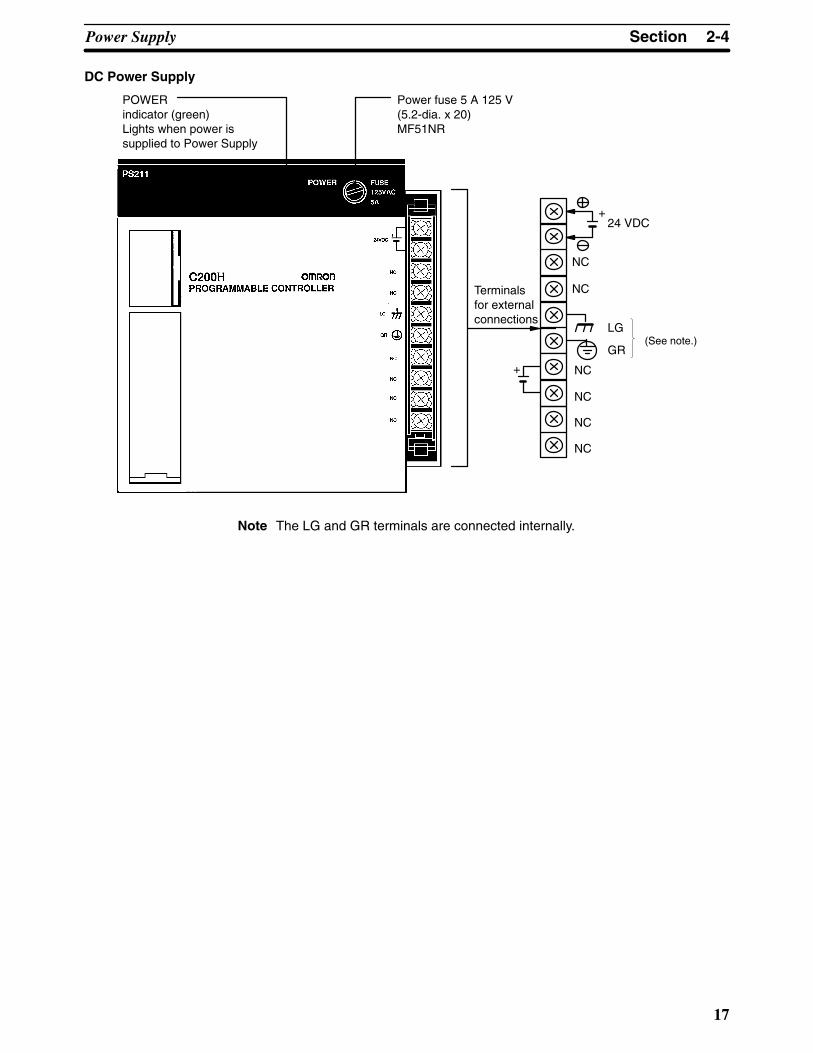
DC Power Supply
+
Terminalsfor externalconnections
POWERindicator (green) Lights when power issupplied to Power Supply
Power fuse 5 A 125 V(5.2-dia. x 20)MF51NR
NC
NC
GR
LG
24 VDC
NC
NC
NC
NC
+
(See note.)
Note The LG and GR terminals are connected internally.
2-5SectionI/O Units
18
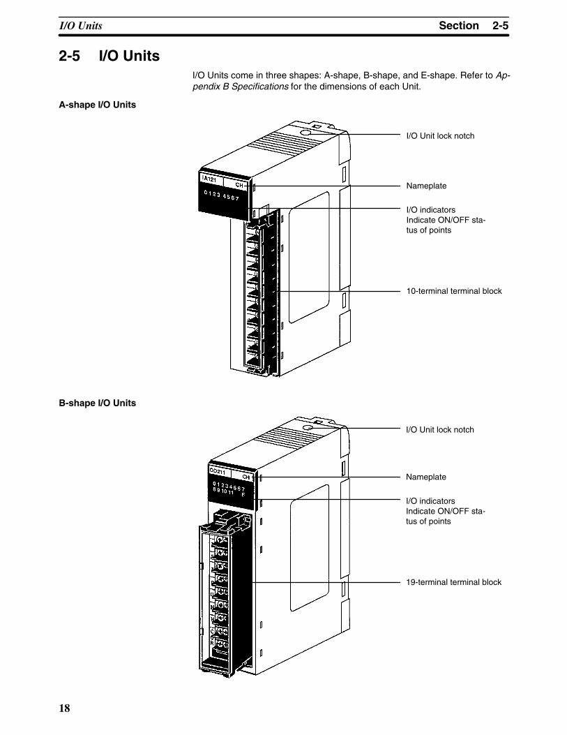
2-5 I/O UnitsI/O Units come in three shapes: A-shape, B-shape, and E-shape. Refer to Ap-pendix B Specifications for the dimensions of each Unit.
A-shape I/O Units
I/O Unit lock notch
Nameplate
I/O indicatorsIndicate ON/OFF sta-tus of points
10-terminal terminal block
B-shape I/O Units
I/O Unit lock notch
Nameplate
I/O indicatorsIndicate ON/OFF sta-tus of points
19-terminal terminal block

2-6SectionMemory Units
19
E-shape I/O Units
I/O Unit lock notch
Nameplate
I/O indicatorsIndicate ON/OFFstatus of points
10-terminal terminal block
2-6 Memory UnitsThere are three types of Memory Units, having three different types of memory.The three types of memory are EPROM, EEPROM, and RAM.
Memory Model Capacity Maximumprogram size
Backup Clock1
EPROM C200H-MP831 8K words 6,974 words --- NO
EEPROM C200H-ME431 4K words 2,878 words
C200H-ME831 8K words 6,974 words
RAM C200H-MR431 4K words 2,878 words Battery NO
C200H-MR831 8K words 6,974 words
C200H-MR432 4K words 2,878 words Capacitor
C200H-MR832 8K words 6,974 words
Fixed DM area(DM 1000 to DM 1999)
I/O table (see note)
UM (ladder program area)
Contents for Memory Unit Registration
Note I/O tables are also saved in the Memory Unit at the time of creation. Therefore, ifthe Memory Unit is set to write-protect, it will be impossible to create an I/O table.

2-6SectionMemory Units
20
The data that you wish to store in an EPROM Unit must first be written to anEPROM Chip, using the PROM Writer. Then the EPROM Chip must be mountedto the inside of the EPROM Unit. Once this has been done, the data cannot bechanged. In addition, the data will be retained indefinitely when the power isturned OFF.
Data can be stored in the EEPROM Unit while the Unit is mounted to the PC. Thedata is retained indefinitely when the power is turned OFF.
Data can be randomly written to and read from the RAM Unit. However, the Unitrequires battery or capacitor back-up in order to retain the information when thepower is OFF. Units with battery back-up can retain their data for approximatelyfive years at room temperature (25°C). Units with capacitor back-up retain theirdata for approximately 20 days at room temperature, but the length of time va-ries with temperature as shown below.
20
10
7
125 50 80
Ambient temperature (°C)
Capacitorback-up time(days)
Two switches are provided on Memory Units, as shown below.
12ON OFF
Write-enable switch(SW1)
Initial mode selector(SW2)
SW1 (the write enable switch) only has an effect if the Unit is a RAM Unit or EE-PROM Unit. Peripheral devices can only write data to these Memory Units ifSW1 is ON. When you wish to write data to this Memory Unit, make sure SW1 isset to the ON position. After you have finished writing the data to the MemoryUnit, turn SW1 to the OFF position so that the data will be protected from anyfurther changes. If you try to write data to the Memory Unit while SW1 is in theOFF position, the message “DISABLED ROM” will appear on the ProgrammingConsole.
SW2 Selects what operating mode the PC will be in when power is applied to theSystem. If there is no peripheral device connected to the CPU, the PC will enterRUN mode when power is applied. If a Programming Console is connected tothe CPU, the PC will enter the mode that the Programming Console is set to. If aperipheral device other than the Programming Console is connected to theCPU, the PC will enter the mode specified by SW2.
The C200H-CPU11-E, unlike the other two CPU models, has an additional bat-tery connected to the CPU. A flag, assigned to the bits listed in the followingtable, indicates where battery failure occurred (in the RAM Unit or in the CPU)and in which Unit.
EPROM Unit
EEPROM Unit
RAM Unit
Switches on MemoryUnits
Battery Failure Flag

2-6SectionMemory Units
21
Model Bit Function
C200H-CPU01-E/03 25308 Battery failure in RAM Unit
C200H-CPU11-E 25308 Battery failure in RAM Unit orCPU
AR2404 Battery failure in CPU
In the following table, the ON/OFF status of the bits indicate where battery failuretook place in the C200H-CPU11-E. For example, when bit 25308 is ON the bat-tery in the CPU failed.
25308 AR2404 Unit in which the battery failed
ON ON CPU
ON OFF RAM Unit


23
SECTION 3Assembly Instructions
When we speak of a PC, we usually think of it as a single object. But actually even the simplest PCs are usually composed ofseveral different devices. In fact a single PC can be physically spread throughout a building, but we still call it one PC.
3-1 Mounting the Units . . . . . . . . . . . . . . . . . . . . . . . . . . . . . . . . . . . . . . . . . . . . . . . . . . . . . . . . 3-2 Memory Packs . . . . . . . . . . . . . . . . . . . . . . . . . . . . . . . . . . . . . . . . . . . . . . . . . . . . . . . . . . . 3-3 System Configurations . . . . . . . . . . . . . . . . . . . . . . . . . . . . . . . . . . . . . . . . . . . . . . . . . . . . .

3-1SectionMounting the Units
24
3-1 Mounting the UnitsThere is no single Unit that can be said to constitute a Rack PC. To build a RackPC, we start with a Backplane. The Backplane for the C200H is shown below.
C200H Backplane
The Backplane is a simple device having two functions. The first is to providephysical support for the Units to be mounted to it. The second is to provide theconnectors and electrical pathways necessary for connecting the Unitsmounted to it.
The core of the PC is the CPU. The CPU contains the program consisting of theseries of steps necessary for the control task. The CPU has a built-in power sup-ply, and fits into the rightmost position of the Backplane.
The CPU of the C200H has no I/O points built in. So, in order to complete the PCwe need to mount one or more I/O Units to the Backplane. Mount the I/O Unit tothe Backplane by locking the top of the I/O Unit into the slot on the Backplane androtating the I/O Unit downwards as shown in the following diagram. Press downon the yellow tab at the bottom of the slot, press the I/O Unit firmly into position,and then release the yellow tab.
3-1SectionMounting the Units
25
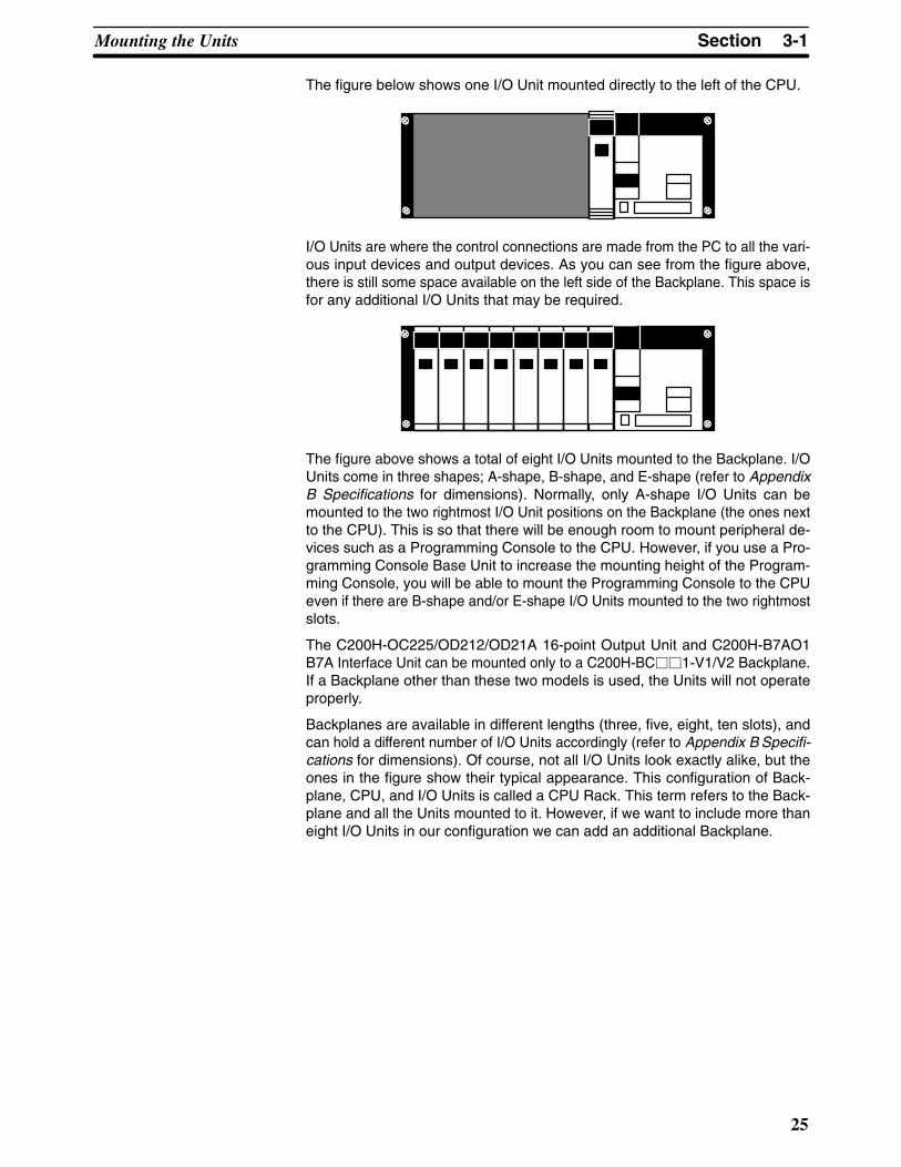
The figure below shows one I/O Unit mounted directly to the left of the CPU.
I/O Units are where the control connections are made from the PC to all the vari-ous input devices and output devices. As you can see from the figure above,there is still some space available on the left side of the Backplane. This space isfor any additional I/O Units that may be required.
The figure above shows a total of eight I/O Units mounted to the Backplane. I/OUnits come in three shapes; A-shape, B-shape, and E-shape (refer to AppendixB Specifications for dimensions). Normally, only A-shape I/O Units can bemounted to the two rightmost I/O Unit positions on the Backplane (the ones nextto the CPU). This is so that there will be enough room to mount peripheral de-vices such as a Programming Console to the CPU. However, if you use a Pro-gramming Console Base Unit to increase the mounting height of the Program-ming Console, you will be able to mount the Programming Console to the CPUeven if there are B-shape and/or E-shape I/O Units mounted to the two rightmostslots.
The C200H-OC225/OD212/OD21A 16-point Output Unit and C200H-B7AO1B7A Interface Unit can be mounted only to a C200H-BC��1-V1/V2 Backplane.If a Backplane other than these two models is used, the Units will not operateproperly.
Backplanes are available in different lengths (three, five, eight, ten slots), andcan hold a different number of I/O Units accordingly (refer to Appendix B Specifi-cations for dimensions). Of course, not all I/O Units look exactly alike, but theones in the figure show their typical appearance. This configuration of Back-plane, CPU, and I/O Units is called a CPU Rack. This term refers to the Back-plane and all the Units mounted to it. However, if we want to include more thaneight I/O Units in our configuration we can add an additional Backplane.

3-1SectionMounting the Units
26
This Backplane has I/O Units mounted to it, but it has no CPU of its own. Theadditional Backplane must also have an Expansion I/O Power Supply mountedto its rightmost position. This configuration of additional Backplane, ExpansionI/O Power Supply, and I/O Units is called an Expansion I/O Rack.
The CPU Rack and Expansion I/O Rack shown above are connected by a Con-necting Cable (the length of Cable between individual Racks can be up to 10 m,but the total length of Cable between all Racks must be within 12 m).
Remember that this whole configuration is still referred to as one PC. It is possi-ble to add up to two Expansion I/O Racks to one CPU Rack. When installing I/OConnecting Cables, cover any unused connectors with the caps provided.

3-2SectionMemory Packs
27
3-2 Memory PacksThe CPU has a removable Memory Pack that stores the user program. MemoryPacks are available with three types of memory; EPROM, EEPROM, and RAM(refer to Section 2-6 Memory Packs). If this is your first C200H, then you musthave a RAM Pack in order to write and test the program you are going to use. Ifthis is not your first C200H and you have a complete, tested program already,you can copy the program to an EPROM or EEPROM Pack for use on thisC200H. The EEPROM chip can be written to without removing the chip from theMemory Pack by using an appropriate peripheral device (refer to Appendix CStandard Models). The EPROM Chip may be programmed using a PROM Writ-er or a FIT Ladder Pack. Then the EPROM Chip must be mounted inside theEPROM Pack.
Note Only PROM Writer Model C500-PRW06 may be used with the SYSMAC C200H.
After the data has been written to the EPROM Chip, mount it to the inside of theEPROM Pack by following these steps.
1, 2, 3... 1. Remove the cover of the EPROM Pack as shown below.
2. Unlock the holding bracket and slide it upward to remove it as shown below
3. Pull the printed circuit board out of the EPROM Pack.
How to Mount anEPROM Chip to theMemory Pack

3-2SectionMemory Packs
28
4. On the printed circuit board there is a socket for the EPROM Chip. On thesocket you will find a notch. Align the notch on the socket with the notch onthe EPROM Chip and mount the EPROM Chip to the socket as shown be-low.
Notch
5. Reassemble the EPROM Pack in the reverse order of disassembly. Duringreassembly, ensure that the circuit board is inserted along the guides on thetop and bottom of the Pack housing and that the projections on the housingfit into the holes in the holding bracket. Be sure to lock the holding bracketinto the right side of the housing. When reassembled, the Pack should ap-pear as shown below.
Circuit board guide
Bracket
Hole
Holding bracket
Circuit board
Circuit board guide
!
3-3SectionSystem Configurations
29
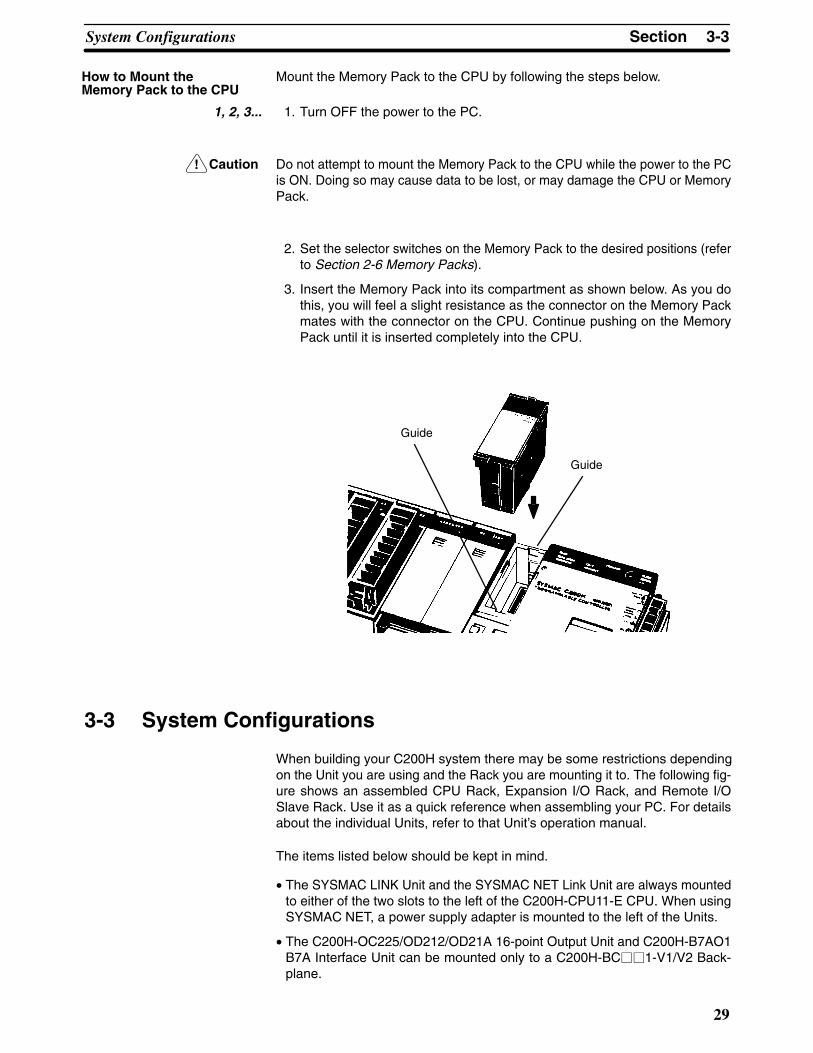
Mount the Memory Pack to the CPU by following the steps below.
1, 2, 3... 1. Turn OFF the power to the PC.
Caution Do not attempt to mount the Memory Pack to the CPU while the power to the PCis ON. Doing so may cause data to be lost, or may damage the CPU or MemoryPack.
2. Set the selector switches on the Memory Pack to the desired positions (referto Section 2-6 Memory Packs).
3. Insert the Memory Pack into its compartment as shown below. As you dothis, you will feel a slight resistance as the connector on the Memory Packmates with the connector on the CPU. Continue pushing on the MemoryPack until it is inserted completely into the CPU.
Guide
Guide
3-3 System Configurations
When building your C200H system there may be some restrictions dependingon the Unit you are using and the Rack you are mounting it to. The following fig-ure shows an assembled CPU Rack, Expansion I/O Rack, and Remote I/OSlave Rack. Use it as a quick reference when assembling your PC. For detailsabout the individual Units, refer to that Unit’s operation manual.
The items listed below should be kept in mind.
• The SYSMAC LINK Unit and the SYSMAC NET Link Unit are always mountedto either of the two slots to the left of the C200H-CPU11-E CPU. When usingSYSMAC NET, a power supply adapter is mounted to the left of the Units.
• The C200H-OC225/OD212/OD21A 16-point Output Unit and C200H-B7AO1B7A Interface Unit can be mounted only to a C200H-BC��1-V1/V2 Back-plane.
How to Mount theMemory Pack to the CPU

3-3SectionSystem Configurations
30
Special I/O Units
•Up to ten Special I/OUnits can be mounted.•Mount Special I/O Unitsto any slot on the CPURack (except the twoslots to the left of theCPU) or the ExpansionI/O Rack.
Host Link Unit and Remote I/O Master Unit
•Up to two Units can bemounted.•Host Link Units and Re-mote I/O Master Unitscan be mounted to anyslot on the CPU Rack(except the two slots tothe left of the CPU) or thethe Expansion I/O Rack.
I/O Units
•I/O Units available with 5, 8,12, or 16 points. •Units available with 10- or19-terminal terminal blocks.•Units with 5 and 8 pointshave 10-terminal terminalblocks and Units with 10 and12 points have 19-terminalterminal blocks.•There are some restrictionson the mounting position of19-terminal I/O Units (refer toAppendix B Specifications).
Memory Packs
•RAM, EPROM, or EE-PROM Packs available.•EEPROM requires an op-tional EEPROM Chip.•EPROM requires a sepa-rately available EPROMChip.
CPUBuilt-in power supply
I/O Unit CoverFor 10-terminal block I/O Units
Backplane3-, 5-, 8-, 10-slot types available
I/O Connecting Cable
•Available in lengths from 30 cm to 1 m.•Total length of I/O Connecting Cablesbetween all Racks must not exceed 12 m.
Optical Fiber Cable or Wire Cable
Up to two Expansion I/ORacks can be connected toone CPU Rack.
Expansion I/O Racks
Expansion I/O Power Supply
Up to five Units can be connected.
Remote I/O Slave Unit
Backplane3-, 5-, or 8-slot types available
Power supply built-inRemote I/O Slave Unit
SYSMAC NET LINK Unit and SYSMAC LINK Unit
• Use up to two Units, mounted to either ofthe two slots to the left of the CPU. •When using either of these two Units theuse of peripheral devices is limited. Refer toSection 4-3 Maximum Current and PowerSupplied.

31
SECTION 4System Connections
In the preceding sections we have covered what all the parts of a PC are and how they should be assembled. This sectionprovides detailed information about the types of considerations involved in making all of the PC connections. Also includedin this section are considerations that should be kept in mind when using the C200H-CPU11-E as the CPU.
4-1 IR Word Allocation . . . . . . . . . . . . . . . . . . . . . . . . . . . . . . . . . . . . . . . . . . . . . . . . . . . . . . . 4-2 Remote I/O . . . . . . . . . . . . . . . . . . . . . . . . . . . . . . . . . . . . . . . . . . . . . . . . . . . . . . . . . . . . . . 4-3 Maximum Current and Power Supplied . . . . . . . . . . . . . . . . . . . . . . . . . . . . . . . . . . . . . . . . 4-4 I/O Connections . . . . . . . . . . . . . . . . . . . . . . . . . . . . . . . . . . . . . . . . . . . . . . . . . . . . . . . . . .

4-1SectionIR Word Allocation
32
4-1 IR Word AllocationEach slot of the Backplane is assigned a hardware word number. This word isaccessible for I/O use only in the given slot. However, standard I/O Units areavailable in 5-, 8-, 12-, and 16-point models. If an I/O Unit other than a 16-pointmodel is mounted, the unused points of that word are accessible only as “workbits” (refer to the C200H Operation Manual). The number of I/O bits available forthe entire system, therefore, varies according to the model of I/O Units used, aswell as the model of Backplanes used. The figure below shows the relationshipbetween the model of I/O Unit and work bits. The shaded bits can only be usedas work bits.
00010203
04
00010203
0405
0607
00010203
0405
0607080910
11
00010203
0405
0607080910
1112
131415
5-point Unit 8-point Unit 12-point Unit 16-point Unit
05
0607080910
1112
131415
080910
1112
131415
12
131415

4-1SectionIR Word Allocation
33
The CPU Rack begins with word 000 at the leftmost slot. The first Expansion I/ORack begins with word 010, and the second Expansion I/O Rack with word 020.The first word of each Rack is fixed, regardless of the model of Backplane used.As with the I/O bits unused by individual I/O Units, the bits of the I/O words un-used by a Backplane can be used as work bits. The following figure shows therelationship between the model of Backplane and I/O words. The shaded bitscan only be used as work bits.
000 005001 002 003 004 006 007 008 009
00
15
00
15
00
15
00
15
00
15
00
15
00
15
00
15
00
15
00
15
000 005001 002 003 004 006 007 008 009
00
15
00
15
00
15
00
15
00
15
00
15
00
15
00
15
00
15
00
15
000 005001 002 003 004 006 007 008 009
00
15
00
15
00
15
00
15
00
15
00
15
00
15
00
15
00
15
00
15
C200H-BC031 Backplane
C200H-BC051-V1 Backplane
C200H-BC081-V1 Backplane
Word
bits
Word
bits
Word
bits
Note The C200H-OC225/OD212/OD21A 16-point Output Unit and C200H-B7AO1B7A Interface Unit can be mounted only to a C200H-BC 1-V1/V2 Backplane.
For example, if a PC consists of three 8-slot Racks with 8-point I/O Unitsmounted to all I/O Unit mounting positions, the number of I/O points for the entirePC will be:
8 points x 8 slots x 3 Racks = 192 points
If a PC consists of three 8-slot Racks with the I/O Unit mounting positions equallydivided between 16-point Input Units and 12-point Output Units, the number ofI/O points for the entire PC will be:
Input points = 16 points x 4 slots x 3 Racks = 192 pointsOutput points = 12 points x 4 slots x 3 Racks = 144 pointsTotal I/O points = 192 + 144 = 336

4-2SectionRemote I/O
34
The following figure shows the word allocation for a fully expanded C200H withthree 8-slot Backplanes.
word000
word005
word001
word002
word003
word004
word006
word007
CPU
word010
word015
word011
word012
word013
word014
word016
word017
word020
PowerSupply
word025
word021
word022
word023
word024
word026
word027
PowerSupply
4-2 Remote I/OThere are limits to how long the normal wiring between the PC and its ExpansionI/O Racks can be. A Remote I/O Unit can extend this distance greatly, so that thePC and its Expansion I/O Racks can even be located in separate buildings.There are two types of Remote I/O Systems, optical and wired.
By locating a Rack farther from the CPU Rack, a Remote I/O System eliminatesthe time and mess in wiring (or changing wiring) to many devices that are sepa-rated from the CPU Rack. Although all I/O points must ultimately be wired indi-vidually, the question is one of distance: Do you want to wire dozens of terminalsall the way across a factory complex or do you want to run a single cable for mostof the distance and then wire individual terminals locally? A PC with an Expan-sion I/O System is called an Expanded PC.
I/O words 100 through 199 and DM words 1000 through 1999 are allocated toSpecial I/O Units. There are limitations to the number and model of Special I/OUnits that can be mounted to a Remote I/O Slave Rack. Provided no other mod-els of Special I/O Units are mounted to a Remote I/O Slave Rack, the maximumnumber of Special I/O Units that can be mounted is shown below for each model.
Group Units Total number
A High-speed Counter, Position Control (NC111/NC112), ASCII, Analog I/O, ID Sensor,Fuzzy Logic Unit
4 Units
B High-density and Mixed I/O, Cam Positioner,Temperature Control, PID Control, Heat/CoolTemperature Control
8 Units
C Temperature Sensor, Voice 6 Units
D Position Control (NC221) 2 Units
When using a combination of A, B, C, and D Units on a Remote I/O Slave Rack,the number of each model of Unit being used must satisfy the following two for-mulas.
3A + B + C + 6D 12A + B + C + D 8
4-3SectionMaximum Current and Power Supplied
35
In addition, when PC Link Units are used, a maximum of ten Special I/O Unitsand PC Link Units total can be mounted to one Expanded PC. When a High-den-sity I/O Unit is mounted to a Remote I/O Slave Rack, the RM001-PV1 or RM201Remote I/O Master Unit must be used.
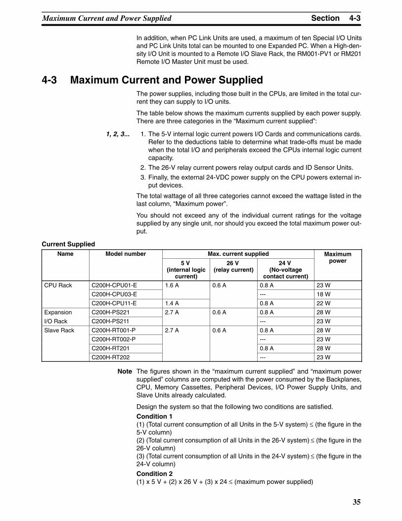
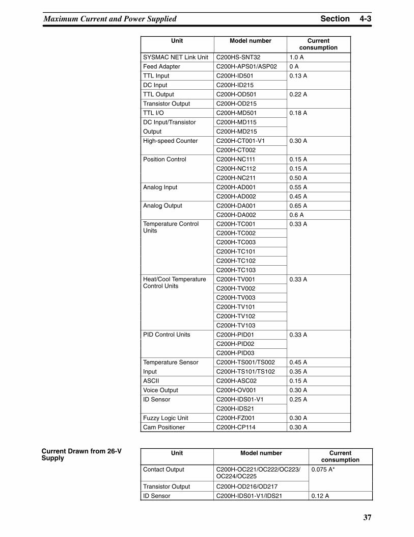
4-3 Maximum Current and Power SuppliedThe power supplies, including those built in the CPUs, are limited in the total cur-rent they can supply to I/O units.
The table below shows the maximum currents supplied by each power supply.There are three categories in the “Maximum current supplied”:
1, 2, 3... 1. The 5-V internal logic current powers I/O Cards and communications cards.Refer to the deductions table to determine what trade-offs must be madewhen the total I/O and peripherals exceed the CPUs internal logic currentcapacity.
2. The 26-V relay current powers relay output cards and ID Sensor Units.
3. Finally, the external 24-VDC power supply on the CPU powers external in-put devices.
The total wattage of all three categories cannot exceed the wattage listed in thelast column, “Maximum power”.
You should not exceed any of the individual current ratings for the voltagesupplied by any single unit, nor should you exceed the total maximum power out-put.
Current SuppliedName Model number Max. current supplied Maximum
5 V (internal logic
current)
26 V (relay current)
24 V (No-voltage
contact current)
power
CPU Rack C200H-CPU01-E 1.6 A 0.6 A 0.8 A 23 W
C200H-CPU03-E --- 18 W
C200H-CPU11-E 1.4 A 0.8 A 22 W
Expansion C200H-PS221 2.7 A 0.6 A 0.8 A 28 W
I/O Rack C200H-PS211 --- 23 W
Slave Rack C200H-RT001-P 2.7 A 0.6 A 0.8 A 28 W
C200H-RT002-P --- 23 W
C200H-RT201 0.8 A 28 W
C200H-RT202 --- 23 W
Note The figures shown in the “maximum current supplied” and “maximum powersupplied” columns are computed with the power consumed by the Backplanes,CPU, Memory Cassettes, Peripheral Devices, I/O Power Supply Units, andSlave Units already calculated.
Design the system so that the following two conditions are satisfied.
Condition 1(1) (Total current consumption of all Units in the 5-V system) ≤ (the figure in the5-V column)(2) (Total current consumption of all Units in the 26-V system) ≤ (the figure in the26-V column)(3) (Total current consumption of all Units in the 24-V system) ≤ (the figure in the24-V column)
Condition 2(1) x 5 V + (2) x 26 V + (3) x 24 ≤ (maximum power supplied)

4-3SectionMaximum Current and Power Supplied
36
Deductions Table
CPU11-E 5-Vconsumption (I/O card)
CPU01/03-E 5-Vconsumption (I/O card)
Peripheral device deductions
≤ 1.4 A ≤ 1.6 A None
> 1.4 A, but ≤ 1.7 A > 1.6 A, but ≤ 1.9 A PROM Writer and CPU-mounting Host Link Unit
> 1.7 A, but ≤ 1.9 A > 1.9 A, but ≤ 2.1 A PROM Writer, CPU-mounting Host Link Unit, Peripheral InterfaceUnit
> 1.9 A, but ≤ 2.1 A > 2.1 A, but ≤ 2.3 A PROM Writer, CPU-mounting Host Link Unit, Peripheral InterfaceUnit, and Printer Interface Unit
Unit Model number Currentconsumption
DC Input C200H-ID211 0.01 A each
C200H-ID212
No-Voltage Contact C200H-ID001
Input C200H-ID002
AC Input C200H-IA121
C200H-IA122/IA122V
C200H-IA221
C200H-IA222/IA222V
AC/DC Input C200H-IM211
C200H-IM212
Contact Output C200H-OC221
C200H-OC222
C200H-OC223
C200H-OC224
C200H-OC225 0.05 A
Transistor Output C200H-OD411 0.14 A
C200H-OD211 0.16 A
C200H-OD212 0.18 A
C200H-OD213 0.14 A
C200H-OD214
C200H-OD216 0.01 A each
C200H-OD217
C200H-OD21A 0.16 A
Triac Output C200H-OA121-E 0.14 A
C200H-OA122-E 0.18 A
C200H-OA223 0.18 A
C200H-OA222V 0.20 A
C200H-OA224 0.27 A
Analog Timer Unit C200H-TM001 0.06 A
B7A Interface Unit C200H-B7AI1 0.10 A
C200H-B7AO1
Host Link C200H-LK101-PV1 0.25 A
C200H-LK201-V1 0.15 A
C200H-LK202-V1 0.25 A
PC Link C200H-LK401 0.35 A
Remote Master C200H-RM001-PV1 0.20 A
C200H-RM201 0.25 A
SYSMAC LINK Unit C200HW-SLK13/SLK14/SLK23/SLK24
0.8 A
Current Drawn from 5-VSupply
4-3SectionMaximum Current and Power Supplied
37
Unit Currentconsumption
Model number
SYSMAC NET Link Unit C200HS-SNT32 1.0 A
Feed Adapter C200H-APS01/ASP02 0 A
TTL Input C200H-ID501 0.13 A
DC Input C200H-ID215
TTL Output C200H-OD501 0.22 A
Transistor Output C200H-OD215
TTL I/O C200H-MD501 0.18 A
DC Input/Transistor C200H-MD115
Output C200H-MD215
High-speed Counter C200H-CT001-V1 0.30 A
C200H-CT002
Position Control C200H-NC111 0.15 A
C200H-NC112 0.15 A
C200H-NC211 0.50 A
Analog Input C200H-AD001 0.55 A
C200H-AD002 0.45 A
Analog Output C200H-DA001 0.65 Ag
C200H-DA002 0.6 A
Temperature ControlU i
C200H-TC001 0.33 AUnits C200H-TC002
C200H-TC003
C200H-TC101
C200H-TC102
C200H-TC103
Heat/Cool TemperatureC l U i
C200H-TV001 0.33 AControl Units C200H-TV002
C200H-TV003
C200H-TV101
C200H-TV102
C200H-TV103
PID Control Units C200H-PID01 0.33 A
C200H-PID02
C200H-PID03
Temperature Sensor C200H-TS001/TS002 0.45 A
Input C200H-TS101/TS102 0.35 A
ASCII C200H-ASC02 0.15 A
Voice Output C200H-OV001 0.30 A
ID Sensor C200H-IDS01-V1 0.25 A
C200H-IDS21
Fuzzy Logic Unit C200H-FZ001 0.30 A
Cam Positioner C200H-CP114 0.30 A
Unit Model number Currentconsumption
Contact Output C200H-OC221/OC222/OC223/OC224/OC225
0.075 A*
Transistor Output C200H-OD216/OD217
ID Sensor C200H-IDS01-V1/IDS21 0.12 A
Current Drawn from 26-VSupply

4-3SectionMaximum Current and Power Supplied
38
Note *With all eight bits on simultaneously.
Unit Model number Currentconsumption
No-Voltage Contact Input Units
C200H-ID001/ID002 0.06 A
The total power consumption for each Rack can be obtained from the followingformulas:
Total power consumption for each Unit + 7 (8)0.6 x 0.55 (1)
CPU Rack = (VA)
7 = CPU power consumption, (8) = Power consumption of the CPU11-E0.6 = 60% efficiency0.55 (1) = Power rate (Number in parentheses: when CPU03-E is used.)
Total power consumption for each Unit + 20.6 x 0.55 (1)
All other Racks = (VA)
2 = I/O Power Supply Unit (Remote I/O Slave Unit) power consumption0.6 = 60% efficiency0.55 (1) = Power rate (Number in parentheses: when PS211, RT002-P or RT202is used.)
Assume that four Contact Output Units, three No-Voltage Contact Input Units,and one Host Link Unit are mounted to a Rack, along with CPU01-E. The follow-ing table shows how the total power consumption is calculated.
Voltage Current consumption Power consumption
5 V (1) 0.01 x 7 + 0.25 = 0.32 A (≤ 1.6 A) (1) x 5 V = 1.6 W
26 V (2) 0.075 x 4 = 0.30 A (≤ 0.6 A) (2) x 26 V = 7.8 W
24 V (3) 0.06 x 3 + 0.3 = 0.48 A (≤ 0.8 A) (3) x 24 V = 11.52 W
Total --- 20.92 W (≤ 23 W)
Assume that six DC Input Units and two High-speed Counter Units are mountedto a Rack, along with the PS221 Power Supply. The following table shows howthe total power consumption is calculated.
Voltage Current consumption Power consumption
5 V (1) 0.01 x 6 + 0.3 x 2 = 0.66 A (≤ 2.7 A) (1) x 5 V = 3.3 W
26 V (2) 0 (2) 0
24 V (3) Service power supply = 0.8 A (≤ 0.8A) (3) x 24 V = 19.2 W
Total --- 22.5 W (≤ 28 W)
Assume that the following Units are mounted to a Rack to which a C200H-CPU11-E is mounted. The following table shows how the total power consump-tion is calculated.
Voltage Current consumption Power consumption
5 V (1) 0.01 x 6 + 0.18 = 0.24 A (≤ 1.1 A) (1) x 5 V = 1.2 W
26 V (2) 0.075 x 4 = 0.30 A(≤0.6 A) (2) x 26V = 7.8 W
24 V (3) 0.06 x 2 + 0.3 = 0.42 A(≤0.8 A) (3) x 24 V = 10.08 W
Total --- 19.08 W (≤ 20.5 W)
• Peripheral Interface Unit (IP006)
• SYSMAC LINK Units (SLK22): 1
• Contact Output Units (OC221): 6
• No-Voltage Contact Input Units (ID001): 2
Current Drawn from 24-VSupply
Calculation Examples
Example 1
Example 2
Example 3

4-3SectionMaximum Current and Power Supplied
39
• High-density and Mixed I/O Units (MD215): 1
• Current for MD215: 0.3 A
Assume that the following Units are mounted to a rack to which is mounted theC200H-CPU11-E. The following table shows how the total power consumptionis calculated.
Voltage Current consumption Power consumption
5 V (1) 0.01 x 5 + 0.3 x 1 = 0.35 A (≤ 0.7 A) (1) x 5 V = 1.75 W
26 V (2) 0 (2) 0
24 V (3) Current=0.5 A(≤0.8 A) (3) x 24 V = 12 W
Total --- 13.75 W (≤ 18.5 W)
• Peripheral Interface Unit (IP006)
• SYSMAC NET Link Units (SNT32): 1
• Central Power Supply Adapter (Current 0): 1
• DC Input Units (ID212): 5
• High-speed Counter Units (CT002): 1
• Current for ID212: 0.5 A
The total power consumption for each Rack can be obtained from the followingformulas:
• CPU Rack: Total power consumption for each Unit + 7 (8) 0.6 x 0.55 (1)
• Expansion I/O Power Supply/Remote I/O Slave Unit:
0.6 x 0.55 (1)Total power consumption for each Unit + 2 (VA)
(VA)
Where:7 = Power consumption of the CPU, (8) = Power consumption of the CPU11-E, 0.6 = 60% efficiency, and 0.55 (1) = Power rate (Number in parentheses: when CPU03-E is used.)
Where:2 = Power consumption of the I/O Power Supply orRemote I/O Slave Unit, 0.6 = 60% efficiency, and0.55 (1) = Power rate (Number in parentheses: whenPS211, RT002-P or RT202 is used.)
Example 4
Calculation of PowerConsumption for EachRack (Examples)

4-4SectionI/O Connections
40
4-4 I/O Connections
Connect the I/O Devices to the I/O Units using AWG 22 (cross-sectional area of0.3 mm2) for 19-terminal terminal blocks and AWG 22 to 18 lead wire (cross-sec-tional area of 0.3 to 0.75 mm2) for 10 terminal terminal blocks. The terminalshave screws with 3.5-mm diameter heads and self-raising pressure plates. Con-nect the lead wires to the terminals as shown below. Tighten the screws with atorque of 0.8 N � m.
If you wish to attach solderless type terminals to the ends of the lead wires, useterminals having the dimensions shown below.
7 mm max.7 mm max.
The terminal block of an I/O Unit can be removed by loosening the mountingscrews. You do not have to remove the lead wires from the terminal block in or-der to remove it from an I/O Unit.
Locks for terminal block.Unlock to remove the terminalblock from the I/O Unit. Makesure the terminal block islocked securely after wiring iscomplete.
Terminal Block

4-4SectionI/O Connections
41
A C200H-COV11 Cover is provided as an I/O Unit cover for Units that use 10Pterminal block connectors. After the I/O wiring has been completed, slide thecover up from the bottom, as shown in the illustration below.
Attach
Remove I/O Unit cover
If a two-wire sensor is used with a 12-VDC or 24-VDC input device, make surethat the following conditions are satisfied. Malfunctions will occur if these condi-tions are not satisfied.• The relationship between the PC ON voltage and the sensor residual voltage is
as follows:VON � VCC – VR
• The relationship between the PC ON current and the sensor control output(load current) is as follows:
IOUT (min) � ION � IOUT (max)ION = (VCC – VR – 1.5 (PC internal residual voltage))/RIN
Connect R bleeder resistance if ION is less than IOUT (min).The constant for bleeder resistance is determined by the following equation.
R � (VCC – VR)/(IOUT (min) – ION)Power W ��(VCC – VR)2/R � 4 (margin)
• The relationship between the PC OFF current and sensor leakage current is asfollows:
IOFF � Ileak
Refer to the information on input and output leakage current on page 56 fordetails.
The value of IOFF depends on the Unit used. For Input Units that have an unspe-cified OFF current, however, the value of IOFF is always 1.8 mA.
VCC: Power supply voltage VR: Sensor output residual voltage
VON: PC ON voltage IOUT: Sensor control output (load current)
ION: PC OFF current Ileak: Sensor leakage current
IOFF: PC OFF current R: Bleeder resistance
RIN: PC input impedance
Two-wire sensor
DC Input Unit
VR R
VCC
RIN
The following are examples of how to connect I/O devices to I/O Units. Duringwiring, work slowly and carefully. If an input device is connected to an OutputUnit, damage may result. Check all I/O devices to make sure they meet the spec-ifications (refer to Appendix B Specifications).
I/O Unit Cover
DC Two-wire SensorConnection Precautions
Wiring Examples

4-4SectionI/O Connections
42
DC Input Units
COM
Contact output
IN DC input
When using the configuration shown below, the sensor and Input Unit shouldreceive their power from the same supply.
+
COM
NPN current output
IN DC input
0 V
Output
7 mA SensorPowerSupply
Currentregulator
+
COM
NPN open-collector output
SensorPowerSupply
IN DC input
0 V
Output
7 mA
+
COM
PNP current output
SensorPowerSupply
IN AC/DC input
0 V
Output
7 mA0 V
The circuit below should be used for I/O devices having a voltage output.
0 V
Output
+COM
Voltage output
SensorPowerSupply
IN DC input
The circuit below should NOT be used for I/O devices having a voltage output.
0 V
Output
+
COM
Voltage output
IN DC input
SensorPowerSupply
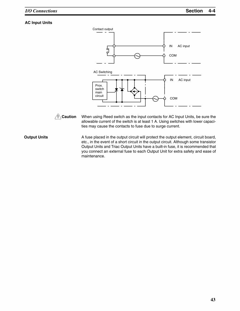
!
4-4SectionI/O Connections
43
AC Input Units
COM
Contact output
IN AC input
COM
AC Switching
IN AC input
Prox.switchmaincircuit
Caution When using Reed switch as the input contacts for AC Input Units, be sure theallowable current of the switch is at least 1 A. Using switches with lower capaci-ties may cause the contacts to fuse due to surge current.
A fuse placed in the output circuit will protect the output element, circuit board,etc., in the event of a short circuit in the output circuit. Although some transistorOutput Units and Triac Output Units have a built-in fuse, it is recommended thatyou connect an external fuse to each Output Unit for extra safety and ease ofmaintenance.
Output Units


45
SECTION 5Installation Environment
This section details the necessary environment and conditions for installation of the PC. For specific instructions on mountingUnits and wiring for I/O and power, refer to Section 2-4 Power Supply and Section 3-3 System Configurations.
5-1 Installation Environment . . . . . . . . . . . . . . . . . . . . . . . . . . . . . . . . . . . . . . . . . . . . . . . . . . . 5-2 Mounting Requirements . . . . . . . . . . . . . . . . . . . . . . . . . . . . . . . . . . . . . . . . . . . . . . . . . . . . 5-3 Duct Work . . . . . . . . . . . . . . . . . . . . . . . . . . . . . . . . . . . . . . . . . . . . . . . . . . . . . . . . . . . . . . 5-4 Preventing Noise . . . . . . . . . . . . . . . . . . . . . . . . . . . . . . . . . . . . . . . . . . . . . . . . . . . . . . . . .
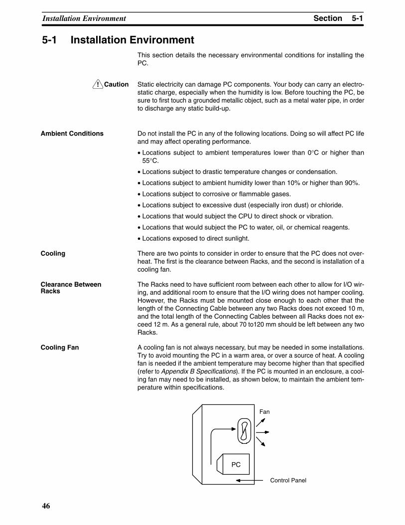
!
5-1SectionInstallation Environment
46
5-1 Installation EnvironmentThis section details the necessary environmental conditions for installing thePC.
Caution Static electricity can damage PC components. Your body can carry an electro-static charge, especially when the humidity is low. Before touching the PC, besure to first touch a grounded metallic object, such as a metal water pipe, in orderto discharge any static build-up.
Do not install the PC in any of the following locations. Doing so will affect PC lifeand may affect operating performance.
• Locations subject to ambient temperatures lower than 0°C or higher than55°C.
• Locations subject to drastic temperature changes or condensation.
• Locations subject to ambient humidity lower than 10% or higher than 90%.
• Locations subject to corrosive or flammable gases.
• Locations subject to excessive dust (especially iron dust) or chloride.
• Locations that would subject the CPU to direct shock or vibration.
• Locations that would subject the PC to water, oil, or chemical reagents.
• Locations exposed to direct sunlight.
There are two points to consider in order to ensure that the PC does not over-heat. The first is the clearance between Racks, and the second is installation of acooling fan.
The Racks need to have sufficient room between each other to allow for I/O wir-ing, and additional room to ensure that the I/O wiring does not hamper cooling.However, the Racks must be mounted close enough to each other that thelength of the Connecting Cable between any two Racks does not exceed 10 m,and the total length of the Connecting Cables between all Racks does not ex-ceed 12 m. As a general rule, about 70 to120 mm should be left between any twoRacks.
A cooling fan is not always necessary, but may be needed in some installations.Try to avoid mounting the PC in a warm area, or over a source of heat. A coolingfan is needed if the ambient temperature may become higher than that specified(refer to Appendix B Specifications). If the PC is mounted in an enclosure, a cool-ing fan may need to be installed, as shown below, to maintain the ambient tem-perature within specifications.
PC
Fan
Control Panel
Ambient Conditions
Cooling
Clearance BetweenRacks
Cooling Fan

5-2SectionMounting Requirements
47
5-2 Mounting Requirements
The PC consists of from one to three Racks. Each Rack must be mounted verti-cally, that is with the printing on the front panels oriented as it would normally beread. The Racks should be mounted one above the other with the CPU Rackuppermost as shown below.
CPU Rack
Expansion Rack
Expansion Rack
These connectorsare not used.Cover them withcaps.
The C200H is approved by Underwriters Laboratories under the condition that,“The device must be mounted vertically for ventilation purposes”.
The PC may be mounted using DIN Rail if desired. This type of mounting is notrequired, and the PC may be directly mounted to any sturdy support meeting theenvironmental specifications (refer to Appendix B Specifications). If you want tomount the PC on DIN Rail, you can order a DIN Rail from OMRON (refer to Ap-pendix B Standard Models). DIN Rails come in the two heights shown below.
7.3-mm Height
16-mm Height
DIN Rail Mounting

5-2SectionMounting Requirements
48
The DIN Rail Mounting Bracket shown below is necessary for mounting the PCto the DIN Rail.
Procedure
1, 2, 3... 1. The following diagram is a view of the back of the Backplane. Attach oneMounting Bracket to the left and right sides of the Backplane as shown be-low.
DIN Rail MountingBracket
There are two Back-plane mountingscrews each on theleft and right sides ofthe Backplane. Usethese screws to at-tach the DIN RailMounting Brackets tothe Backplane.
Backplane
2. Mount the Backplane to the DIN Rail so that the claws on the MountingBrackets fit into the upper portion of the DIN Rail as shown below.
DIN Rail Mounting Bracket
DIN RailThis claw fits into the DIN Rail
Backplane
DIN Rail MountingBracket

5-3SectionDuct Work
49
3. Loosen the screws attaching the Mounting Brackets to the Backplane. Slidethe Backplane upward as shown below so that the Mounting Bracket andBackplane clamp securely onto the DIN Rail. Tighten the screws.
DIN Rail Mounting Bracket
DIN Rail
Slide this screw to the top of theprojection and then tighten it.Projections
Hold-down bracket
5-3 Duct Work
If power cables carrying more than 10 A 400 V, or 20 A 220 V must be run along-side the I/O wiring (that is, in parallel with it), at least 300 mm must be left be-tween the power cables and the I/O wiring as shown below.
Low current cable
Control cable
Power cable
300 mm min.
300 mm min.
1
2
3
Grounding at resistanceof less than 100 W
Where: 1 = I/O wiring2 = General control wiring3 = Power cables

5-4SectionPreventing Noise
50
If the I/O wiring and power cables must be placed in the same duct (for example,where they are connected to the equipment), they must be shielded from eachother using grounded metal plates.
Metal plate (iron)
1 2 3
200 mm min.
Grounding at resistanceof less than 100 �
Where: 1 = I/O wiring2 = General control wiring3 = Power cables
5-4 Preventing NoiseIn order to prevent noise from interfering with the operation of the PC, use AWG14 twisted-pair cables (cross-sectional area of at least 2 mm2). Avoid mountingthe PC close to high-power equipment, and make sure the point of installation isat least 200 mm away from power cables as shown in the following diagram.
PC
200 mm min.
200 mm min.
Power lines
Whenever possible, use wiring conduit to hold the I/O wiring. Standard wiringconduit should be used, and it should be long enough to completely contain theI/O wiring and keep it separated from other cables.

51
SECTION 6Power Considerations
Use a commercially available 100 to 120 VAC, 200 to 240 VAC, or 24 VDC power source, according to the model of PC youare using (refer to Appendix B Specifications). Expansion I/O Racks, if used, must also be connected to the power source. Ifpossible, use independent power sources for the PC, input devices, and output devices. All Racks of the PC may be connectedto one power source.
6-1 Grounding . . . . . . . . . . . . . . . . . . . . . . . . . . . . . . . . . . . . . . . . . . . . . . . . . . . . . . . . . . . . . . . 6-2 Insulation . . . . . . . . . . . . . . . . . . . . . . . . . . . . . . . . . . . . . . . . . . . . . . . . . . . . . . . . . . . . . . . 6-3 Emergency Stop . . . . . . . . . . . . . . . . . . . . . . . . . . . . . . . . . . . . . . . . . . . . . . . . . . . . . . . . . . 6-4 Wiring . . . . . . . . . . . . . . . . . . . . . . . . . . . . . . . . . . . . . . . . . . . . . . . . . . . . . . . . . . . . . . . . . .

6-3SectionEmergency Stop
52
6-1 GroundingThe Line Ground (LG) terminal is a noise-filtered neutral terminal that does notnormally require grounding. If electrical noise is a problem, however, this termi-nal should be connected to the Ground (GR) terminal.
To avoid electrical shock, attach a grounded (earth ground) AWG 14 wire (cross-sectional area of at least 2 mm2) to the GR terminal. The resistance to groundmust be less than 100 �. Do not use a wire longer than 20 m. Care must be tak-en, because ground resistance is affected by environmental conditions such assoil composition, water content, time of year, and the length of time since thewire was laid underground.
PC operation may be adversely affected if the ground wire is shared with otherequipment, or if the ground wire is attached to the metal structure of a building.When using an Expansion I/O Rack, the Rack must also be grounded to the GRterminal. The same ground can be used for all connections.
6-2 InsulationIf a separate ground is being supplied to different Racks, Insulating Plates mustbe used to insulate the Racks from each other. Insulating Plates are supplied asan accessory (refer to Appendix B Specifications).
6-3 Emergency StopAn external relay should be used to form an emergency stop circuit that turns thepower to the PC OFF in the event of an emergency. An emergency stop routinein the PC program is not sufficient to ensure safety. The circuit shown below is anexample of an emergency stop circuit.
MCB1
Power section
Control section
CR1MCB2
PC RUN output
CR1
PC
DC input/output
Surgesuppressor
Twisted
Transformer ornoise filter
+
-
DC voltageregulator
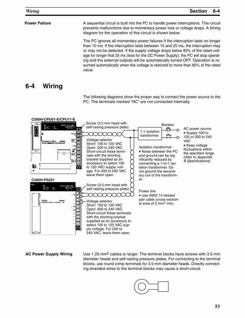
6-4SectionWiring
53
A sequential circuit is built into the PC to handle power interruptions. This circuitprevents malfunctions due to momentary power loss or voltage drops. A timingdiagram for the operation of this circuit is shown below.
The PC ignores all momentary power failures if the interruption lasts no longerthan 10 ms. If the interruption lasts between 10 and 25 ms, the interruption mayor may not be detected. If the supply voltage drops below 85% of the rated volt-age for longer that 25 ms (less for the DC Power Supply), the PC will stop operat-ing and the external outputs will be automatically turned OFF. Operation is re-sumed automatically when the voltage is restored to more than 85% of the ratedvalue.
6-4 Wiring
The following diagrams show the proper way to connect the power source to thePC. The terminals marked “NC” are not connected internally.
1:1 isolationtransformer
Voltage selectorShort: 100 to 120 VACOpen: 200 to 240 VACShort-circuit these termi-nals with the shortingbracket supplied as anaccessory to select 100to 120 VAC supply volt-age. For 200 to 240 VACleave them open.
Voltage selectorShort: 100 to 120 VACOpen: 200 to 240 VACShort-circuit these terminalswith the shorting bracketsupplied as an accessory toselect 100 to 120 VAC sup-ply voltage. For 200 to240 VAC, leave them open.
Isolation transformer• Noise between the PCand ground can be sig-nificantly reduced byconnecting a 1-to-1 iso-lation transformer. Donot ground the second-ary coil of the transform-er.
Power line• Use AWG 14 twistedpair cable (cross-section-al area of 2 mm2 min).
AC power source• Supply 100 to120 or 200 to 240VAC• Keep voltagefluctuations withinthe specified range(refer to AppendixB Specifications)
Screw (3.5 mm head withself-raising pressure plate)
Screw (3.5 mm head withself-raising pressure plate)
Breaker
C200H-CPU01-E/CPU11-E
C200H-PS221
AC Power Supply Wiring Use 1.25-mm2 cables or larger. The terminal blocks have screws with 3.5-mmdiameter heads and self-raising pressure plates. For connecting to the terminalblocks, use round crimp terminals for 3.5-mm diameter heads. Directly connect-ing stranded wires to the terminal blocks may cause a short-circuit.
Power Failure

!
6-4SectionWiring
54
Caution Tighten the AC Power Supply terminals on the terminal blocks to the torque of0.8 N � m. Insufficient tightening may cause short-circuiting, malfunction, orburning.
Voltage selectorShort: 100 to 120 VACOpen: 200 to 240 VACShort-circuit these terminalswith the shorting bracketsupplied as an accessory toselect 100 to 120 VAC sup-ply voltage. For 200 to 240VAC, leave them open.
Power line• Use AWG 14 twistedpair cable (cross-section-al area of 2 mm2 min).
Screw (3.5 mm head withself-raising pressure plate)
• Supply 24 VDC• Keep voltagefluctuations withinthe specified range(refer to AppendixB Specifications)
Screw (3.5 mm head withself-raising pressure plate)
Breaker
C200H-CPU03-E
C200H-PS211
Power Supply Wiring Use 1.25-mm2 cables or larger. The terminal blocks have screws with 3.5-mmdiameter heads and self-raising pressure plates. For connecting to the terminalblocks, use round crimp terminals for 3.5-mm diameter heads. Directly connect-ing stranded wires to the terminal blocks may cause a short-circuit.
Tighten the terminals on the terminal blocks to the torque of 0.8 N � m.

55
SECTION 7Safety Considerations
There are certain safety requirements to be considered when installing the PC. Some of these, such as the emergency stopcircuit (refer to Section 2-4 Power Supply), are part of the initial wiring. The considerations described below should be kept inmind when operating the PC and when connecting I/O devices to the PC.
7-1 Interlock Circuits . . . . . . . . . . . . . . . . . . . . . . . . . . . . . . . . . . . . . . . . . . . . . . . . . . . . . . . . . 7-2 Wiring . . . . . . . . . . . . . . . . . . . . . . . . . . . . . . . . . . . . . . . . . . . . . . . . . . . . . . . . . . . . . . . . . .

7-2SectionWiring
56
7-1 Interlock CircuitsWhen the PC controls an operation such as the clockwise and counterclockwiseoperation of a motor, provide an external interlock such as the one shown belowto prevent both the forward and reverse outputs from turning ON at the sametime.
PC
MC2
MC1
00501
00502
MC1
MC2
Motor clockwise
Motor counterclockwise
Interlock circuit
This circuit prevents outputs MC1 and MC2 from ever both being ON at the sametime. Even if the PC is programmed improperly or malfunctions, the motor is pro-tected.
7-2 Wiring
The 24 VDC output of the CPU and Expansion I/O Power Supply may be used topower other devices. The output current of these supplies is limited to 0.3 A. Aseparate power supply must be provided if the devices being powered require ahigher current.
When two-wire sensors, such as photoelectric sensors, proximity sensors, orlimit switches with LEDs, are connected to the PC as input devices, the input bitmay be turned ON erroneously by leakage current. In order to prevent this, con-nect a bleeder resistor across the input as shown below.
Sensor
Inputpowersupply
Bleederresistor
R PC
If the leakage current is less than 1.3 mA, there should be no problem. If the leak-age current is greater than 1.3 mA, determine the value and rating for thebleeder resistor using the following formulas.
7.22.4 x I – 3––––––R = k� max.
W =2.3R––– W min.
I = leakage current in mA
Power Supply Output
Input Leakage Current

7-2SectionWiring
57
If there is a possibility of leakage current causing a transistor or triac to malfunc-tion, connect a bleeder resistor across the output as shown below.
PC Load power supply
OUT
COM
Bleeder resistor
LR
Determine the value and rating for the bleeder resistor using the following for-mula.
Eon
I–––R
Where
Eon = ON voltage of the load
I = leakage current in mA
R = bleeder resistance
When connecting a transistor or triac Output Unit to an output device having ahigh surge current (such as an incandescent lamp), care must be taken to avoiddamage to the Output Unit. The transistor and triac Output Units are capable ofwithstanding a surge current of ten times the rated current. If the surge currentfor a particular device exceeds this amount, use the circuit shown below to pro-tect the Output Unit.
R
L
+
OUT
COM
Another way of protecting the Output Unit lets the load draw a small current(about one third the rated current) while the output is OFF, significantly reducingthe surge current. This circuit (shown below) not only reduces the surge current,but also reduces the voltage across the load at the same time.
RL
+
OUT
COM
When connecting TTL circuits to transistor Output Units, it is necessary to con-nect a pull-up resistor and a CMOS IC between the two. This is because of theresidual voltage left on the transistor output after the output turns OFF.
Output Leakage Current
Output Surge Current
Transistor OutputResidual Voltage

7-2SectionWiring
58
When an inductive load is connected to an I/O Unit, it is necessary to connect asurge suppressor or diode in parallel with the load as shown below. This is sothat the back EMF generated by the load will be absorbed.
Relay Output UnitTransistor Output Unit
LOUT
COM
Surge suppressor
LOUT
COM
Relay Output UnitTriac Output Unit
+
Diode
Be sure to take appropriate measures when any electrical device likely to pro-duce noise is connected to the PC as a load. Devices generating noise of morethan 1,200 V (such as electromagnetic relays and valves) require noise sup-pression. For noise sources running off of AC power, connect a diode in parallelwith the coil of each device.
When mounting a CPU Rack and an Expansion I/O Rack together on a mountingplate, be sure to provide a solid ground the mounting plate. The mounting platemust be plated with a highly conductive surface in order to ensure noise immu-nity.
Inductive Load SurgeSuppressor
Electrical Noise
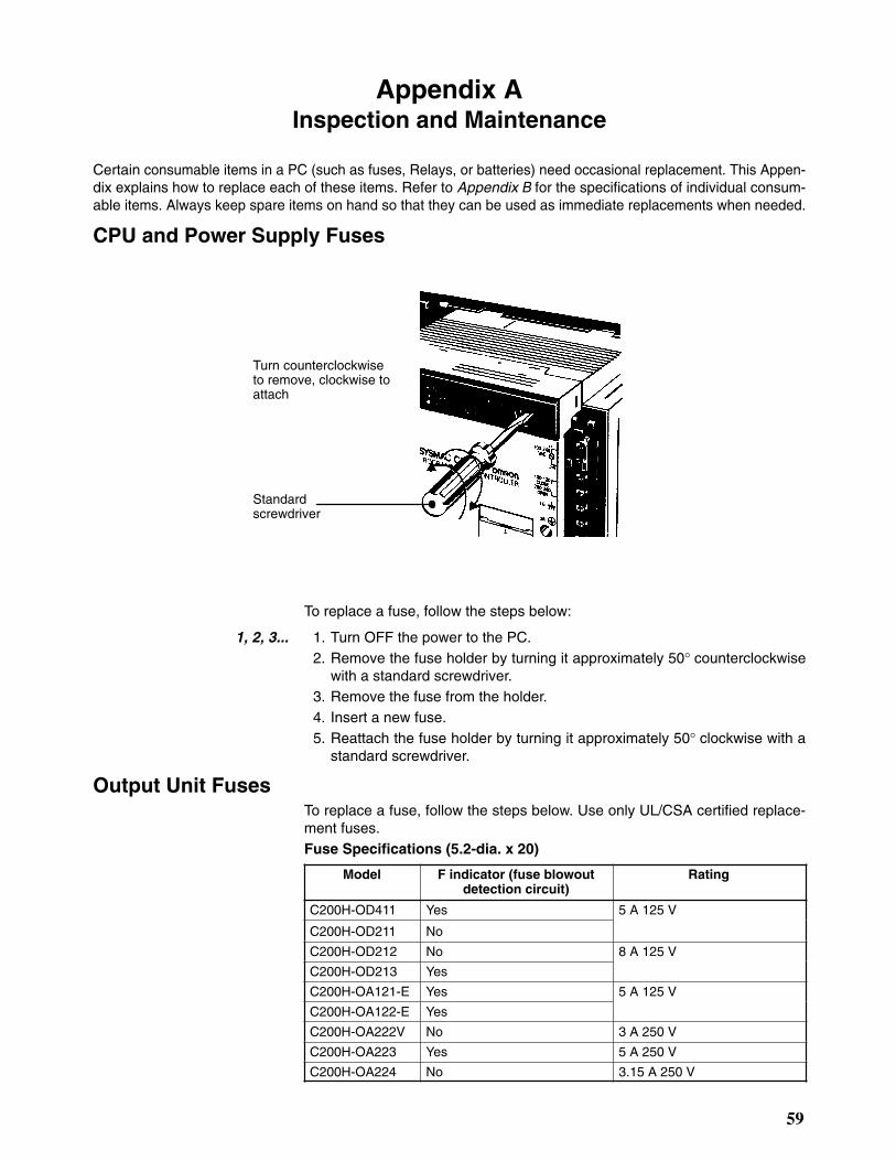
59
Appendix AInspection and Maintenance
Certain consumable items in a PC (such as fuses, Relays, or batteries) need occasional replacement. This Appen-dix explains how to replace each of these items. Refer to Appendix B for the specifications of individual consum-able items. Always keep spare items on hand so that they can be used as immediate replacements when needed.
CPU and Power Supply Fuses
Standardscrewdriver
Turn counterclockwiseto remove, clockwise toattach
To replace a fuse, follow the steps below:
1, 2, 3... 1. Turn OFF the power to the PC.2. Remove the fuse holder by turning it approximately 50° counterclockwise
with a standard screwdriver.3. Remove the fuse from the holder.4. Insert a new fuse.5. Reattach the fuse holder by turning it approximately 50° clockwise with a
standard screwdriver.
Output Unit FusesTo replace a fuse, follow the steps below. Use only UL/CSA certified replace-ment fuses.Fuse Specifications (5.2-dia. x 20)
Model F indicator (fuse blowoutdetection circuit)
Rating
C200H-OD411 Yes 5 A 125 V
C200H-OD211 No
C200H-OD212 No 8 A 125 V
C200H-OD213 Yes
C200H-OA121-E Yes 5 A 125 V
C200H-OA122-E Yes
C200H-OA222V No 3 A 250 V
C200H-OA223 Yes 5 A 250 V
C200H-OA224 No 3.15 A 250 V

Appendix AInspection and Maintenance
60
1, 2, 3... 1. Turn OFF the power to the PC.
2. Detach the terminal block by unlocking the lock levers at the top and bottomof the terminal block.
3. While pushing down the lock lever on the Backplane with a screwdriver asshown below, remove the Output Unit.
4. Remove the screw from the top of the Unit (Phillips screwdriver).
5. Detach the case from the Unit (flat-blade screwdriver).
6. Pull out the printed circuit board.
7. Insert a new fuse. A spare fuse is provided inside the rear of the case whenthe Unit is delivered.
8. Reassemble in reverse order of assembly.
Output Unit RelaysTo replace a Relay, follow the steps below:
1, 2, 3... 1. Turn OFF the power to the PC.
2. Detach the terminal block by unlocking the lock levers at the top and bottomof the terminal block.

Appendix AInspection and Maintenance
61
3. While pushing down the lock lever on the Backplane with a screwdriver asshown below, remove the Output Unit.
4. Remove the screw from the top of the Unit (Phillips screwdriver).
5. Detach the case from the Unit (flat-blade screwdriver).
6. Pull out the printed circuit board. The Relays are placed on the PC boards ofindividual Units as shown in the figures below.
OC221/OC224
1234567
0
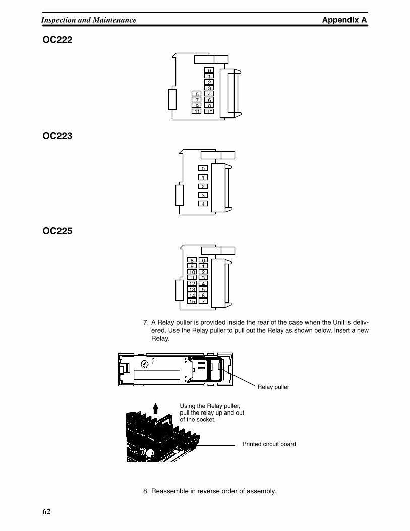
Appendix AInspection and Maintenance
62
OC222
123467
0
5
810
911
OC223
1
2
3
4
0
OC225
1234567
09101112131415
8
7. A Relay puller is provided inside the rear of the case when the Unit is deliv-ered. Use the Relay puller to pull out the Relay as shown below. Insert a newRelay.
Relay puller
Printed circuit board
Using the Relay puller,pull the relay up and outof the socket.
8. Reassemble in reverse order of assembly.
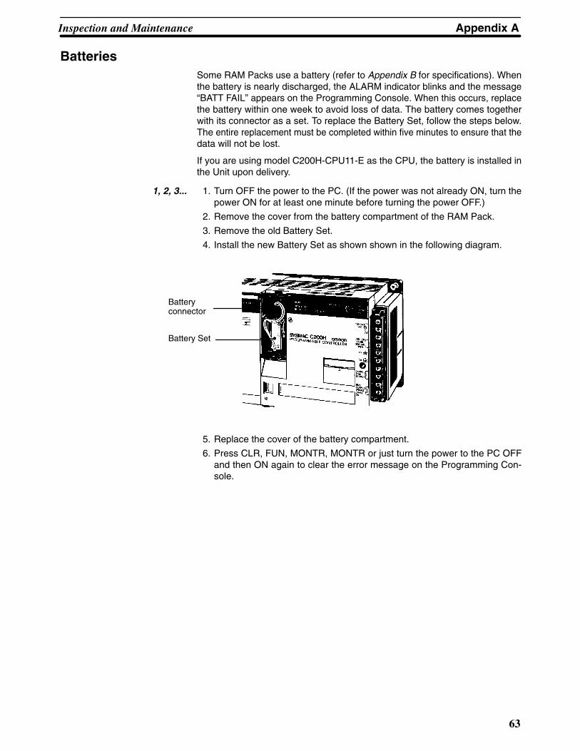
Appendix AInspection and Maintenance
63
BatteriesSome RAM Packs use a battery (refer to Appendix B for specifications). Whenthe battery is nearly discharged, the ALARM indicator blinks and the message“BATT FAIL” appears on the Programming Console. When this occurs, replacethe battery within one week to avoid loss of data. The battery comes togetherwith its connector as a set. To replace the Battery Set, follow the steps below.The entire replacement must be completed within five minutes to ensure that thedata will not be lost.
If you are using model C200H-CPU11-E as the CPU, the battery is installed inthe Unit upon delivery.
1, 2, 3... 1. Turn OFF the power to the PC. (If the power was not already ON, turn thepower ON for at least one minute before turning the power OFF.)
2. Remove the cover from the battery compartment of the RAM Pack.
3. Remove the old Battery Set.
4. Install the new Battery Set as shown shown in the following diagram.
Batteryconnector
Battery Set
5. Replace the cover of the battery compartment.
6. Press CLR, FUN, MONTR, MONTR or just turn the power to the PC OFFand then ON again to clear the error message on the Programming Con-sole.


!
65
Appendix BSpecifications
The following series of figures and tables provides a complete set of specifications for each Unit of the C200H.Note that I/O Units may take on one of three different shapes. Thus I/O Units are sometimes referred to as A-shapeI/O Units, B-shape, or E-shape I/O Units. Refer to the figures at the end of the I/O Unit specifications for the exactdimensions of these three shapes of I/O Unit.
General Specifications
Item C200H-CPU01-E, CPU11-E/PS221 C200H-CPU03/PS211
Supply Voltage 100 to 120/200 to 240 VAC selectable50/60 Hz
24 VDC
Operating Voltage Range 85 to 132/170 to 264 VAC 20.4 to 26.4 VDC
Power Consumption 120 VA max. per Rack (Backplane) 40 W max. per Rack (Backplane)
Surge Current Approx. 5 times the normal current
Output Capacity CPU Rack: 3 A 5 VDC (1.6 A supplied to I/O Units)Refer to Section 4-4 Special Considerations for C200H-CPU11
Expansion I/O Unit Rack: 3 A 5 VDC (2.7 A supplied to I/O Units)
Fuse 2 A 250 V 5.2 dia. x 20 (MF51NR) 2 A 125 V 5.2 dia. x 20 (MF51NR)
24 VDC Output 0.3 A 24 VDC +10%/–20% None
Dielectric Strength 2,000 VAC 50/60 Hz for 1 minute betweenAC terminals and housing 500 VAC 50/60Hz for 1 minute between DC terminals andhousing leakage current: 10 mA max.
See Caution.
Noise Immunity 1,000 Vp-p, pulse width: 100 ns to 1 �s, rise time: 1 ns
Vibration Mechanical durability: 10 to 35 Hz, 1 mm double amplitude (24.5 m/s2) in X, Y, and Zdirections, for 2 hours each (When mounted on DIN Rail, 16.7 Hz, 1 mm doubleamplitude (4.9 m/s2) in X, Y, and Z directions, for 1 hour each) Malfunction durability: 2 to 55 Hz, 19.6 m/s2, in X, Y, and Z directions, for 20 minuteseach (When mounted on DIN Rail, 2 to 55 Hz, 2.94 m/s2, in X, Y, and Z directions, for 20minutes each)
Shock 98 m/s2 in X, Y, and Z directions, 3 times each
Ambient Temperature Operating: 0° to 55°C (0° to 45°C for Programming Console) Storage: –20° to 65°CHumidity 35 to 85% RH (without condensation)
Atmosphere Must be free of the following:• Corrosive gases• Abrupt temperature changes• Direct sunlight• Dust, salt, or metal filings• Water, oil, or chemicals
Grounding Less than 100 �
Degree of Protection Mounted in a panel
Weight 6 kg max.
Caution When conducting an insulation resistance or dielectric strength test, disconnect the power supplyterminals from the LG and GR terminals. Do not conduct a dielectric strength test on the C200H-CPU03-E, PS211, RT002-P, or RT202 Units. The power supply input line and internal circuit of the24 VDC Power Supply are not isolated from each other. If a dielectric strength test is conducted,the Power Supply will be damaged.
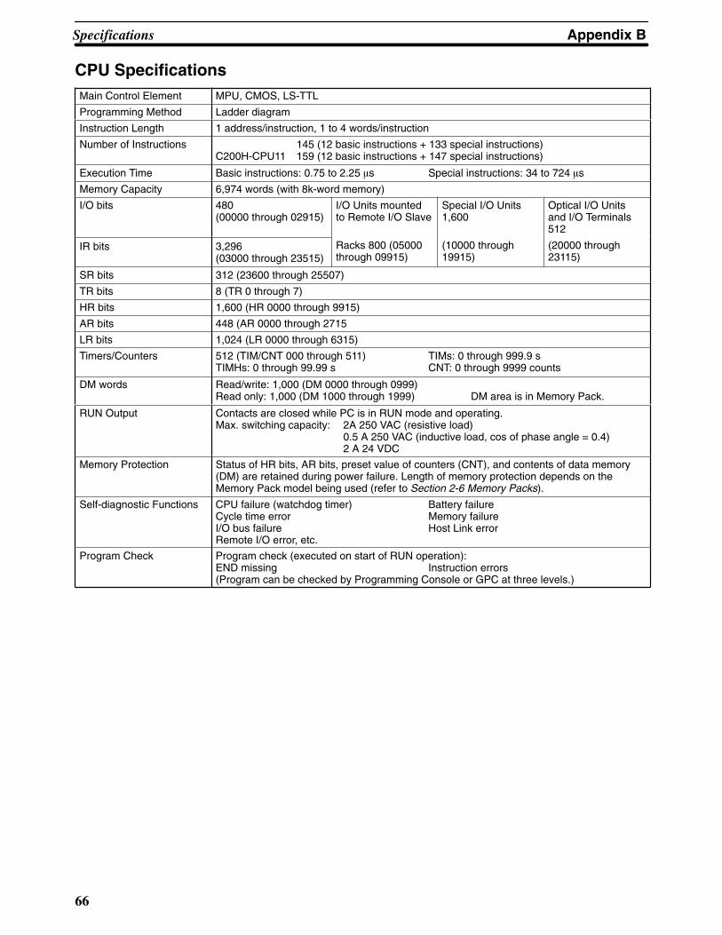
Appendix BSpecifications
66
CPU SpecificationsMain Control Element MPU, CMOS, LS-TTL
Programming Method Ladder diagram
Instruction Length 1 address/instruction, 1 to 4 words/instruction
Number of Instructions 145 (12 basic instructions + 133 special instructions)C200H-CPU11 159 (12 basic instructions + 147 special instructions)
Execution Time Basic instructions: 0.75 to 2.25 �s Special instructions: 34 to 724 �s
Memory Capacity 6,974 words (with 8k-word memory)
I/O bits 480(00000 through 02915)
I/O Units mountedto Remote I/O Slave
Special I/O Units1,600
Optical I/O Unitsand I/O Terminals512
IR bits 3,296(03000 through 23515)
Racks 800 (05000through 09915)
(10000 through19915)
(20000 through23115)
SR bits 312 (23600 through 25507)
TR bits 8 (TR 0 through 7)
HR bits 1,600 (HR 0000 through 9915)
AR bits 448 (AR 0000 through 2715
LR bits 1,024 (LR 0000 through 6315)
Timers/Counters 512 (TIM/CNT 000 through 511) TIMs: 0 through 999.9 sTIMHs: 0 through 99.99 s CNT: 0 through 9999 counts
DM words Read/write: 1,000 (DM 0000 through 0999)Read only: 1,000 (DM 1000 through 1999) DM area is in Memory Pack.
RUN Output Contacts are closed while PC is in RUN mode and operating.Max. switching capacity: 2A 250 VAC (resistive load)
0.5 A 250 VAC (inductive load, cos of phase angle = 0.4)2 A 24 VDC
Memory Protection Status of HR bits, AR bits, preset value of counters (CNT), and contents of data memory(DM) are retained during power failure. Length of memory protection depends on theMemory Pack model being used (refer to Section 2-6 Memory Packs).
Self-diagnostic Functions CPU failure (watchdog timer) Battery failureCycle time error Memory failureI/O bus failure Host Link errorRemote I/O error, etc.
Program Check Program check (executed on start of RUN operation):END missing Instruction errors(Program can be checked by Programming Console or GPC at three levels.)

Appendix BSpecifications
67
AC Input Unit C200H-IA121Rated Input Voltage 100 to 120 VAC 50/60 Hz
Operating Input Voltage 85 to 132 VAC 50/60 Hz
Input Impedance 9.7 k� (50 Hz), 8 k� (60 Hz)
Input Current 10 mA typical (at 100 VAC)
ON Voltage 60 VAC min.
OFF Voltage 20 VAC max.
ON Response Time 35 ms max. (at 100 VAC, 25°C)
OFF Response Time 55 ms max. (at 100 VAC, 25°C)
No. of Circuits 1 (8 points/common)
Internal Current Consumption 10 mA 5 VDC max.
Weight 250 g max.
Dimensions A-shape
Circuit Configuration
IN
IN
COM
Internalcircuit
100 to 120 VAC
470 �
Input LED indicator
0.33 �F
330 k�
910 �
Terminal Connections
COM
A0
A1
A2
A3
A4
A5
A6
A7
A8
A9
0
1
2
3
4
5
6
7
NC
100 to 120 VAC

Appendix BSpecifications
68
AC Input Unit C200H-IA122/IA122VRated Input Voltage 100 to 120 VAC 50/60 Hz
Operating Input Voltage 85 to 132 VAC 50/60 Hz
Input Impedance 9.7 k� (50 Hz), 8 k� (60 Hz)
Input Current 10 mA typical (at 100 VAC)
ON Voltage 60 VAC min.
OFF Voltage 20 VAC max.
ON Response Time 35 ms max. (at 100 VAC, 25°C)
OFF Response Time 55 ms max. (at 100 VAC, 25°C)
No. of Circuits 1 (16 points/common)
Internal Current Consumption 10 mA 5 VDC max.
Weight IA122: 300 g max.IA122V: 400 g max.
Dimensions B-shape
Circuit Configuration
IN
IN
COM
Internalcircuit
100 to 120 VAC
470 �
Input LED indicator
0.33 �F
330 k�
910 �
Terminal Connections
A0
A1
A2
A3
A4
A5
A6
A7
A8
B0
B1
B2
B3
B4
B5
B6
B7
B8
B9COM
1
3
5
7
9
11
13
15NC
0
2
4
6
8
10
12
14
NC
100 to 120 VAC

Appendix BSpecifications
69
AC Input Unit C200H-IA221Rated Input Voltage 200 to 240 VAC 50/60 Hz
Operating Input Voltage 170 to 264 VAC 50/60 Hz
Input Impedance 21 k� (50 Hz), 18 k� (60 Hz)
Input Current 10 mA typical (at 200 VAC)
ON Voltage 120 VAC min.
OFF Voltage 40 VAC max.
ON Response Time 35 ms max. (at 200 VAC, 25°C)
OFF Response Time 55 ms max. (at 200 VAC, 25°C)
No. of Circuits 1 (8 points/common)
Internal Current Consumption 10 mA 5 VDC max.
Weight 250 g max.
Dimensions A-shape
Circuit Configuration
IN
IN
COM
Internalcircuit
200 to 240 VAC
Input LED indicator
820 W (IA221)0.15 �F
680 k�
910 �
Terminal Connections
COM
A0
A1
A2
A3
A4
A5
A6
A7
A8
A9
0
1
2
3
4
5
6
7
NC
100 to 120 VAC
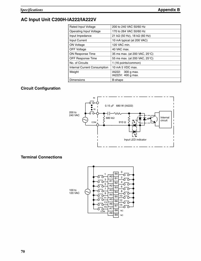
Appendix BSpecifications
70
AC Input Unit C200H-IA222/IA222VRated Input Voltage 200 to 240 VAC 50/60 Hz
Operating Input Voltage 170 to 264 VAC 50/60 Hz
Input Impedance 21 k� (50 Hz), 18 k� (60 Hz)
Input Current 10 mA typical (at 200 VAC)
ON Voltage 120 VAC min.
OFF Voltage 40 VAC max.
ON Response Time 35 ms max. (at 200 VAC, 25°C)
OFF Response Time 55 ms max. (at 200 VAC, 25°C)
No. of Circuits 1 (16 points/common)
Internal Current Consumption 10 mA 5 VDC max.
Weight IA222: 300 g max.IA222V: 400 g max.
Dimensions B-shape
Circuit Configuration
IN
IN
COM
Internalcircuit
200 to 240 VAC
Input LED indicator
680 W (IA222)0.15 �F
680 k�
910 �
Terminal Connections
A0
A1
A2
A3
A4
A5
A6
A7
A8
B0
B1
B2
B3
B4
B5
B6
B7
B8
B9COM
1
3
5
7
9
11
13
15NC
0
2
4
6
8
10
12
14
NC
100 to 120 VAC

Appendix BSpecifications
71
No-Voltage Contact Input Unit C200H-ID001
Input Voltage No-voltage contact/NPN output type (negativecommon)
Input Impedance 3 k�
Input Current 7 mA typical
ON Voltage (14.4 VDC min.)
OFF Voltage (5.0 VDC max.)
ON Response Time 1.5 ms max. (no-voltage contact, at 25°C)
OFF Response Time 1.5 ms max. (no-voltage contact, at 25°C)
No. of Circuits 1 (8 points/common)
Internal Current Consumption 10 mA 5 VDC max.
Weight 200 g max.
Dimensions A-shape
Circuit Configuration
Internal 24 VDCpower supply
+
–
IN
IN
COM
Internalcircuit
3 k�
0.01 �F
Input LED indicator
1.8
k�
0.3 A24 VDC
Powersupply
CPU, Expansion I/O PowerSupply, Remote I/O Slave Unit
Current
Note The power is supplied to the Input Units from the 24 VDC output of the Power Supply of the CPU, ExpansionI/O Unit, or Remote I/O Unit. Never connect 24 VDC output terminals to the input terminals or COM termi-nals.
Terminal Connections
COM
A0
A1
A2
A3
A4
A5
A6
A7
A8
A9
0
1
2
3
4
5
6
7
NC
Current(NPN output)

Appendix BSpecifications
72
No-Voltage Contact Input Unit C200H-ID002
Input Voltage No-voltage contact/NPN output type (positivecommon)
Input Impedance 3 k�
Input Current 7 mA typical
ON Voltage (14.4 VDC min.)
OFF Voltage (5.0 VDC max.)
ON Response Time 1.5 ms max. (no-voltage contact, at 25°C)
OFF Response Time 1.5 ms max. (no-voltage contact, at 25°C)
No. of Circuits 1 (8 points/common)
Internal Current Consumption 10 mA 5 VDC max.
Weight 200 g max.
Dimensions A-shape
Circuit Configuration
Internal 24 VDCpower supply
+
–
IN
IN
COM
Internalcircuit
3 k�
0.01 �F
Input LED indicator
1.8k�
0.3 A24 VDC
Powersupply
CPU, Expansion I/O PowerSupply, Remote I/O Slave Unit
Current
Note The power is supplied to the Input Units from the 24 VDC output of the Power Supply of the CPU, ExpansionI/O Unit, or Remote I/O Unit. Never connect 24 VDC output terminals to the input terminals or COM termi-nals.
Terminal Connections
COM
A0
A1
A2
A3
A4
A5
A6
A7
A8
A9
0
1
2
3
4
5
6
7
NC
Current(PNP output)

Appendix BSpecifications
73
DC Input Unit C200H-ID211Rated Input Voltage 12 to 24 VDC
Operating Input Voltage 10.2 to 26.4 VDC
Input Impedance 2 k�
Input Current 10 mA (at 24 VDC)
ON Voltage 10.2 VDC min.
OFF Voltage 3.0 VDC max.
ON Response Time 1.5 ms max. (at 24 VDC, 25°C)
OFF Response Time 1.5 ms max. (at 24 VDC, 25°C)
No. of Circuits 1 (8 point/common)
Internal Current Consumption 10 mA 5 VDC max.
Weight 200 g max.
Dimensions A-shape
Circuit Configuration
IN
IN
COM
Internalcircuit
12 to 24 VDC
2 k�
0.01 �F
Input LED indicator
1.8
k�
Terminal Connections
COM
12 to 24 VDC
A0
A1
A2
A3
A4
A5
A6
A7
A8
A9
0
1
2
3
4
5
6
7
NC

Appendix BSpecifications
74
DC Input Unit C200H-ID212Rated Input Voltage 24 VDC
Operating Input Voltage 20.4 to 26.4 VDC
Input Impedance 3 k�
Input Current 7 mA (at 24 VDC)
ON Voltage 14.4 VDC min.
OFF Voltage 5.0 VDC max.
ON Response Time 1.5 ms max. (at 24 VDC, 25°C)
OFF Response Time 1.5 ms max. (at 24 VDC, 25°C)
No. of Circuits 1 (16 points/common)
Internal Current Consumption 10 mA 5 VDC max.
Weight 300 g max.
Dimensions B-shape
Circuit Configuration
IN
IN
COM
Internalcircuit
24 VDC
3 k�
0.01 �F
Input LED indicator
1.8k�
Terminal Connections
A0
A1
A2
A3
A4
A5
A6
A7
A8
B0
B1
B2
B3
B4
B5
B6
B7
B8
B9COM
24 VDC
1
3
5
7
9
11
13
15NC
0
2
4
6
8
10
12
14
NC

Appendix BSpecifications
75
AC/DC Input Unit C200H-IM211Rated Input Voltage 12 to 24 VDC
Operating Input Voltage 10.2 to 26.4 VDC
Input Impedance 2 k�
Input Current 10 mA typical (at 24 VDC)
ON Voltage 10.2 VDC min.
OFF Voltage 3.0 VDC max.
ON Response Time 15 ms max. (at 24 VDC, 25°C)
OFF Response Time 15 ms max. (at 24 VDC, 25°C)
No. of Circuits 1 (8 points/common)
Internal Current Consumption 10 mA 5 VDC max.
Weight 200 g max.
Dimensions A-shape
Circuit Configuration
IN
IN
COM
Internalcircuit
12 to24 VAC/DC
2 k�
0.01 �F
Input LED indicator
1.8k�
Terminal Connections
COM
A0
A1
A2
A3
A4
A5
A6
A7
A8
A9
0
1
2
3
4
5
6
7
NC
12 to 24 VAC/DC
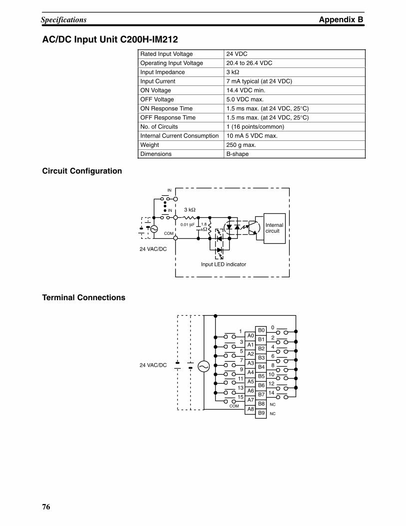
Appendix BSpecifications
76
AC/DC Input Unit C200H-IM212Rated Input Voltage 24 VDC
Operating Input Voltage 20.4 to 26.4 VDC
Input Impedance 3 k�
Input Current 7 mA typical (at 24 VDC)
ON Voltage 14.4 VDC min.
OFF Voltage 5.0 VDC max.
ON Response Time 1.5 ms max. (at 24 VDC, 25°C)
OFF Response Time 1.5 ms max. (at 24 VDC, 25°C)
No. of Circuits 1 (16 points/common)
Internal Current Consumption 10 mA 5 VDC max.
Weight 250 g max.
Dimensions B-shape
Circuit Configuration
IN
IN
COM
Internalcircuit
24 VAC/DC
3 k�
0.01 �F
Input LED indicator
1.8k�
Terminal Connections
A0
A1
A2
A3
A4
A5
A6
A7
A8
B0
B1
B2
B3
B4
B5
B6
B7
B8
B9COM
1
3
5
7
9
11
13
15NC
0
2
4
6
8
10
12
14
NC
24 VAC/DC

Appendix BSpecifications
77
Triac Output Unit C200H-OA222V
Max. Switching Capacity 0.3 A 250 VAC, 50/60 Hz (2 A/Unit)
Min. Switching Capacity 10 mA (resistive load)/40 mA (inductive load)10 VAC
Leakage Current 3 mA (100 VAC) max./6 mA (200 VAC) max.
Residual Voltage 1.2 V max.
ON Response Time 1/2 of load frequency or less.
OFF Response Time 1/2 of load frequency or less.
No. of Circuits 1 (12 points/common)
Internal Current Consumption 200 mA 5 VDC max.
Fuse Rating 3 A 250 V (5.2-dia.x20)
Power for External Supply N/A
Weight 400 g max.
Dimensions B-shape
Circuit Configuration
L
Internalcircuit
OUT
COM
OUTOutput indicator
L
250 VAC max.
Fuse: 3 A 250 V (5.2-dia.x20) MF51SH (JIS)
Fuse
Note No blown fuse detector circuit is provided.
Terminal Connections
A0
A1
A2
A3
A4
A5
A6
A7
A8
B0
B1
B2
B3
B4
B5
B6
B7
B8
B9COM
1
3
5
7
9
11
NC
0
2
4
6
8
10
NC
NC
NC
NC250 VAC max. (0.3 A max., 2 A/Unit)
L
L
L
L
L
L
L
L
L
L
L
L
NC

Appendix BSpecifications
78
Triac Output Unit C200H-OA121-EMax. switching capacity 1 A 120 VAC, 50/60 Hz (4 A/Unit)
Min. switching capacity 10 mA (resistive load)/40 mA (inductive load)10 VAC
Leakage Current 3 mA (100 VAC) max.
Residual Voltage 1.2 V max.
ON Response Time 1 ms max.
OFF Response Time 1/2 of load frequency or less.
No. of Circuits 1 (8 points/common)
Internal Current Consumption 140 mA 5 VDC max.
Fuse Rating 5 A 125 V (5.2-dia.x20)
Power for External Supply N/A
Weight 250 g max.
Dimensions A-shape
Circuit Configuration
Internalcircuit
L
OUT
COM
OUTOutput LEDindicator
L
120 VAC max.
F LED
Fuse blowoutdetection circuit
Fuse: 5 A 125 V (5.2-dia.x20) GGS (Nagasawa)
Fuse
Note When the fuse blows F LED lights and bit 08 turns ON. Bits 08 through15 cannot be used as work bits.
Terminal Connections
A0A1
A2A3A4
A5A6A7
A8A9
0123
456
7
L
L
L
L
L
L
L
L
COM
NC
120 VAC max(1 A max. 4 A/Unit)

Appendix BSpecifications
79
Triac Output Unit C200H-OA122-EMax. Switching Capacity 1.2 A 120 VAC, 50/60 Hz (4 A/Unit)
Max. Inrush Current 15 A (pulse width: 100 ms)30 A (pulse width: 10 ms)
Min. Switching Capacity 100 mA 10 VAC/50 mA 24 VAC/10 mA 100 VACmin.
Leakage Current 1.5 mA (120 VAC) max.
Residual Voltage 1.5 VAC max. (50 to 1,200 mA)/ 5 VAC max. (10 to50 mA)
ON Response Time 1 ms max.
OFF Response Time 1/2 of load frequency+1 ms or less.
No. of Circuits 1 (8 points/common)
Internal Current Consumption 180 mA 5 VDC max.
Fuse Rating 5 A 125 V (5.2-dia.x20)
Power for External Supply N/A
Weight 300 g max.
Dimensions E-shape
Circuit Configuration
L
Internalcircuit
OUT
COM
OUTOutput indicator
L
120 VAC max.
Fuse: 5 A 125 V (5.2-dia.x20) GGS (Nagasawa)
Fuse
F indicator
Fuse blowoutdetection circuit
Note When the fuse blows, the F indicator lights and bit 08 turns ON. Bits 08 through 15 cannot be used as workbits.
Terminal Connections
A0
A1
A2
A3
A4
A5
A6
A7
A8
A9
0
1
2
3
4
5
6
7
L
L
L
L
L
L
L
L
COM
120 VAC max.(1.2 A max. 4 A/Unit)
NC

Appendix BSpecifications
80
Triac Output Unit C200H-OA223Max. Switching Capacity 1.2 A 250 VAC, 50/60 Hz (4 A/Unit)
Max. Inrush Current 15 A (pulse width: 100 ms)30 A (pulse width: 10 ms)
Min. Switching Capacity 100 mA 10 VAC/50 mA 24 VAC/10 mA 100 VACmin.
Leakage Current 1.5 mA (120 VAC) max./3 mA (240 VAC) max.
Residual Voltage 1.5 VAC max. (50 to 1,200 mA)/ 5 VAC max. (10 to50 mA)
ON Response Time 1 ms max.
OFF Response Time 1/2 of load frequency+1 ms or less.
No. of Circuits 1 (8 points/common)
Internal Current Consumption 180 mA 5 VDC max.
Fuse Rating 5 A 250 V (5.2-dia.x20)
Power for External Supply N/A
Weight 300 g max.
Dimensions E-shape
Circuit Configuration
L
Internalcircuit
OUT
COM
OUTOutput indicator
L
250 VAC max.
Fuse: 5 A 250 V (5.2-dia.x20) HT (SOC)
Fuse
F indicator
Fuse blowoutdetection circuit
Note When the fuse blows F LED lights and bit 08 turns ON. Bits 08 through15 cannot be used as work bits.
Terminal Connections
A0
A1
A2
A3
A4
A5
A6
A7
A8
A9
0
1
2
3
4
5
6
7
L
L
L
L
L
L
L
L
COM
250 VAC max.(1.2 A max. 4 A/Unit)
NC
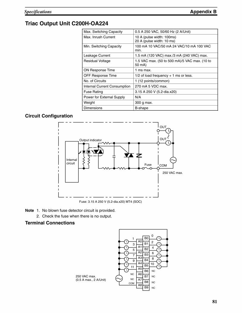
Appendix BSpecifications
81
Triac Output Unit C200H-OA224Max. Switching Capacity 0.5 A 250 VAC, 50/60 Hz (2 A/Unit)
Max. Inrush Current 10 A (pulse width: 100ms)20 A (pulse width: 10 ms)
Min. Switching Capacity 100 mA 10 VAC/50 mA 24 VAC/10 mA 100 VACmin.
Leakage Current 1.5 mA (120 VAC) max./3 mA (240 VAC) max.
Residual Voltage 1.5 VAC max. (50 to 500 mA)/5 VAC max. (10 to50 mA)
ON Response Time 1 ms max.
OFF Response Time 1/2 of load frequency + 1 ms or less.
No. of Circuits 1 (12 points/common)
Internal Current Consumption 270 mA 5 VDC max.
Fuse Rating 3.15 A 250 V (5.2-dia.x20)
Power for External Supply N/A
Weight 300 g max.
Dimensions B-shape
Circuit Configuration
L
Internalcircuit
OUT
COM
OUTOutput indicator
L
250 VAC max.
Fuse: 3.15 A 250 V (5.2-dia.x20) MT4 (SOC)
Fuse
Note 1. No blown fuse detector circuit is provided.2. Check the fuse when there is no output.
Terminal Connections
A0
A1
A2
A3
A4
A5
A6
A7
A8
B0
B1
B2
B3
B4
B5
B6
B7
B8
B9COM
1
3
5
7
9
11
NC
0
2
4
6
8
10
NC
NC
NC
NC250 VAC max. (0.5 A max., 2 A/Unit)
L
L
L
L
L
L
L
L
L
L
L
L
NC

Appendix BSpecifications
82
Contact Output Unit C200H-OC221Max. switching capacity 2 A 250 VAC (cos of phase angle = 1), 2 A
250 VAC (cos of phase angle = 0.4), 2 A 24 VDC 8 A/Unit
Min. switching capacity 10 mA 5 VDC
Relay G6B-1174P-FD-US (24 VDC) w/socket
Service Life of Relay Electrical: 500,000 operations (resistive load)/100,000 operations (inductive load) Mechanical: 50,000,000 operations
ON Response Time 10 ms max.
OFF Response Time 10 ms max.
No. of Circuits 1 (8 points/common)
Internal Current Consumption 10 mA 5 VDC max. 75 mA 25 VDC (8 points ONsimultaneously.)
Weight 250 g max.
Dimensions A-shape
Circuit Configuration
Internalcircuit
L
L
OUT
COM
OUTOutput LED indicator
250 VAC 24 VDC max.
Terminal Connections
COM
A0
A1
A2
A3
A4
A5
A6
A7
A8
A9
0
1
2
3
4
5
6
7
NC
250 VAC 24 VDC max. (inductive load: 2 A resistive load: 2 A) (8 A/Unit)
L
L
L
L
L
L
L
L

Appendix BSpecifications
83
Contact Output Unit C200H-OC222Max. switching capacity 2 A 250 VAC (cos of phase angle = 1), 2 A
250 VAC (cos of phase angle = 0.4), 2 A 24 VDC 8 A/Unit
Min. switching capacity 10 mA 5 VDC
Relay G6B-1174P-FD-US (24 VDC) w/socket
Service Life of Relay Electrical: 500,000 operations (resistive load)/100,000 operations (inductive load)Mechanical: 50,000,000 operations
ON Response Time 10 ms max.
OFF Response Time 10 ms max.
No. of Circuits 1 (12 points/common) 8 points max. can be ONsimultaneously.
Internal Current Consumption 10 mA 5 VDC max. 75 mA 25 VDC (8 points ONsimultaneously.)
Weight 300 g max.
Dimensions B-shape
Circuit Configuration
Internalcircuit
L
L
OUT
COM
OUTOutput LED indicator
250 VAC24 VDC max.
Terminal Connections
A0
A1
A2
A3
A4
A5
A6
A7
A8
B0
B1
B2
B3
B4
B5
B6
B7
B8
B9COM
1
3
5
7
9
11
NC
0
2
4
6
8
10
NC
NC
NC
NC
NC
250 VAC 24 VDC max. (inductive load: 2 A resistive load: 2 A) (8 A/Unit)
L
L
L
L
L
L
L
L
L
L
L
L

Appendix BSpecifications
84
Contact Output Unit C200H-OC223Max. switching capacity 2 A 250 VAC (cos of phase angle = 1), 2 A
250 VAC (cos of phase angle = 0.4), 2 A 24 VDC10 A/Unit
Min. switching capacity relay 10 mA 5 VDC
Service Life of Relay Electrical: 500,000 operations (resistive load)/100,000 operations (inductive load) Mechanical: 50,000,000 operations
ON Response Time 10 ms max.
OFF Response Time 10 ms max.
No. of Circuits 5 independent contacts
Internal Current Consumption 10 mA 5 VDC max. 75 mA 25 VDC (8 points ONsimultaneously.)
Weight 250 g max.
Dimensions A-shape
Circuit Configuration
Internalcircuit
L
Output LED indicator
250 VAC24 VDC max.
OUT
OUT
Terminal Connections
250VAC 24 VDC max. (inductive load: 2 A resistive load: 2 A) (8 A/Unit)
A0
A1
A2
A3
A4
A5
A6
A7
A8
A9
0
c0
1
c1
2
c2
3
c3
4
c4
L
L
L
L
L

Appendix BSpecifications
85
Contact Output Unit C200H-OC224
Max. switching capacity 2 A 250 VAC (cos of phase angle = 1), 2 A250 VAC (cos of phase angle = 0.4), 2 A 24 VDC16 A/Unit
Min. switching capacity relay 10 mA 5 VDC
Service Life of Relay Electrical: 500,000 operations (resistive load)/100,000 operations (inductive load) Mechanical: 50,000,000 operations
ON Response Time 10 ms max.
OFF Response Time 10 ms max.
No. of Circuits 8 independent contacts
Internal Current Consumption 10 mA 5 VDC max. 75 mA 25 VDC (8 points ONsimultaneously.)
Weight 300 g max.
Dimensions B-shape
Circuit Configuration
Internalcircuit
L
Output LED indicator
250 VAC24 VDC max.
OUT
OUTc
Terminal Connections
B0
B1
B2
B3
B4
B5
B6
B7
B8
B9
A0
A1
A2
A3
A4
A5
A6
A7
A8
c0
c1
c2
c3
c4
c5
c6
c7
L
L
L
L
L
L
L
L
0
1
2
3
4
5
6
7
250 VAC 24VDC max. (in-ductive load: 2A resistiveload: 2 A) (16A/Unit)
NC
NCNC

Appendix BSpecifications
86
Contact Output Unit C200H-OC225Max. switching capacity 2 A 250 VAC (cos of phase angle = 1), 2 A
250 VAC (cos of phase angle = 0.4), 2 A 24 VDC 8 A/Unit
Min. switching capacity 10 mA 5 VDC
Relay G6B-1174P-FD-US (24 VDC) w/socket
Service Life of Relay Electrical: 500,000 operations (resistive load)/100,000 operations (inductive load)Mechanical: 50,000,000 operations
ON Response Time 10 ms max.
OFF Response Time 10 ms max.
No. of Circuits 1 (16 points/common) 8 points max. can be ONsimultaneously.
Internal Current Consumption 50 mA 5 VDC max. 75 mA 25 VDC (8 points ONsimultaneously.)
Weight 400 g max.
Dimensions B-shape
Circuit Configuration
Internalcircuit
L
L
OUT
COM
OUTOutput LED indicator
250 VAC24 VDC max.
Terminal Connections
A0A1
A2A3A4
A5A6A7
A8
B0
B1B2B3
B4B5B6
B7B8B9COM
1
357
911
NC
0
246
810
NC
250 VAC 24 VDC max. (inductive load: 2 A resistive load: 2 A) (8 A/Unit)
L
L
L
L
L
L
L
L
L
L
L
L
15
L
L
121314L
L
Note This Unit must be mounted to a C200H-BC��1-V1/V2 Backplane.

Appendix BSpecifications
87
Transistor Output Unit C200H-OD211Max. switching capacity 0.3 A 24 VDC +10%/–15% (2 A/Unit)
Min. switching capacity None
Leakage Current 0.1 mA max.
Residual Voltage 1.4 V max.
ON Response Time 0.2 ms max.
OFF Response Time 0.3 ms max.
No. of Circuits 1 (12 points/common)
Internal Current Consumption 160 mA 5 VDC max.
Fuse Rating 5 A 125 V (5.2-dia.x20)
Power for External Supply 25 mA 24 VDC +10%/–15% max.
Weight 300 g max.
Dimensions B-shape
Circuit Configuration
Internalcircuit
L
OUT
COM
OUT
Output LED indicator
L
+ V
Fuse: GGS (Nagasawa)
24 VDC
Fuse
Note No blown fuse detector circuit is provided.
Terminal Connections
A0
A1
A2
A3
A4
A5
A6
A7
A8
B0
B1
B2
B3
B4
B5
B6
B7
B8
B9COM (0 V)
1
3
5
7
9
11
NC
0
2
4
6
8
10
NC
NC
NC
NC
24 VDC (0.3 A max., 2 A/Unit)
L
L
L
L
L
L
L
L
L
L
L
L
+ 24 VDC
Note Be sure to supply power to B9; otherwise current will leak through the load while the output is OFF.

Appendix BSpecifications
88
Transistor Output Unit C200H-OD212
Max. switching capacity 0.3 A 24 VDC +10%/–15% (4.8 A/Unit)
Min. switching capacity None
Leakage Current 0.1 mA max.
Residual Voltage 1.4 V max.
ON Response Time 0.2 ms max.
OFF Response Time 0.3 ms max.
No. of Circuits 1 (16 points/common)
Internal Current Consumption 180 mA 5 VDC max.
Fuse Rating 8 A 125 V (5.2-dia.x20)
Power for External Supply 35 mA 24 VDC +10%/–15% max.
Weight 350 g max.
Dimensions B-shape
Circuit Configuration
Internalcircuit
L
OUT
COM
OUTOutput LED indicator
L
+ V
Fuse: GGS (Nagasawa)
24 VDCFuse
Note No blown fuse detector circuit is provided.
Terminal Connections
A0
A1
A2
A3
A4
A5
A6
A7
A8
B0
B1
B2
B3
B4
B5
B6
B7
B8
B9COM (0 V)
1
3
5
7
9
11
NC
0
2
4
6
8
10
24 VDC (0.3 A max )
L
L
L
L
L
L
L
L
L
L
L
L
+ 24 VDC
L
L
13
15
L
L
12
14
Note 1. Be sure to supply power to B9; otherwise current will leak through the load while the output is OFF.
2. This Unit must be mounted to a C200H-BC��1-V1/V2 Backplane.
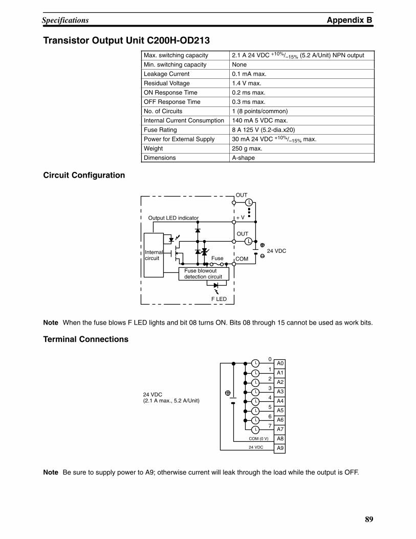
Appendix BSpecifications
89
Transistor Output Unit C200H-OD213Max. switching capacity 2.1 A 24 VDC +10%/–15% (5.2 A/Unit) NPN output
Min. switching capacity None
Leakage Current 0.1 mA max.
Residual Voltage 1.4 V max.
ON Response Time 0.2 ms max.
OFF Response Time 0.3 ms max.
No. of Circuits 1 (8 points/common)
Internal Current Consumption 140 mA 5 VDC max.
Fuse Rating 8 A 125 V (5.2-dia.x20)
Power for External Supply 30 mA 24 VDC +10%/–15% max.
Weight 250 g max.
Dimensions A-shape
Circuit Configuration
Internalcircuit
L
OUT
COM
OUT
Output LED indicator
L
+ V
24 VDC
Fuse blowoutdetection circuit
Fuse
F LED
Note When the fuse blows F LED lights and bit 08 turns ON. Bits 08 through 15 cannot be used as work bits.
Terminal Connections
24 VDC (2.1 A max., 5.2 A/Unit)
L
L
L
L
L
L
L
L
A0
A1
A2
A3
A4
A5
A6
A7
A8
A9
0
1
2
3
4
5
6
7
COM (0 V)
24 VDC
Note Be sure to supply power to A9; otherwise current will leak through the load while the output is OFF.
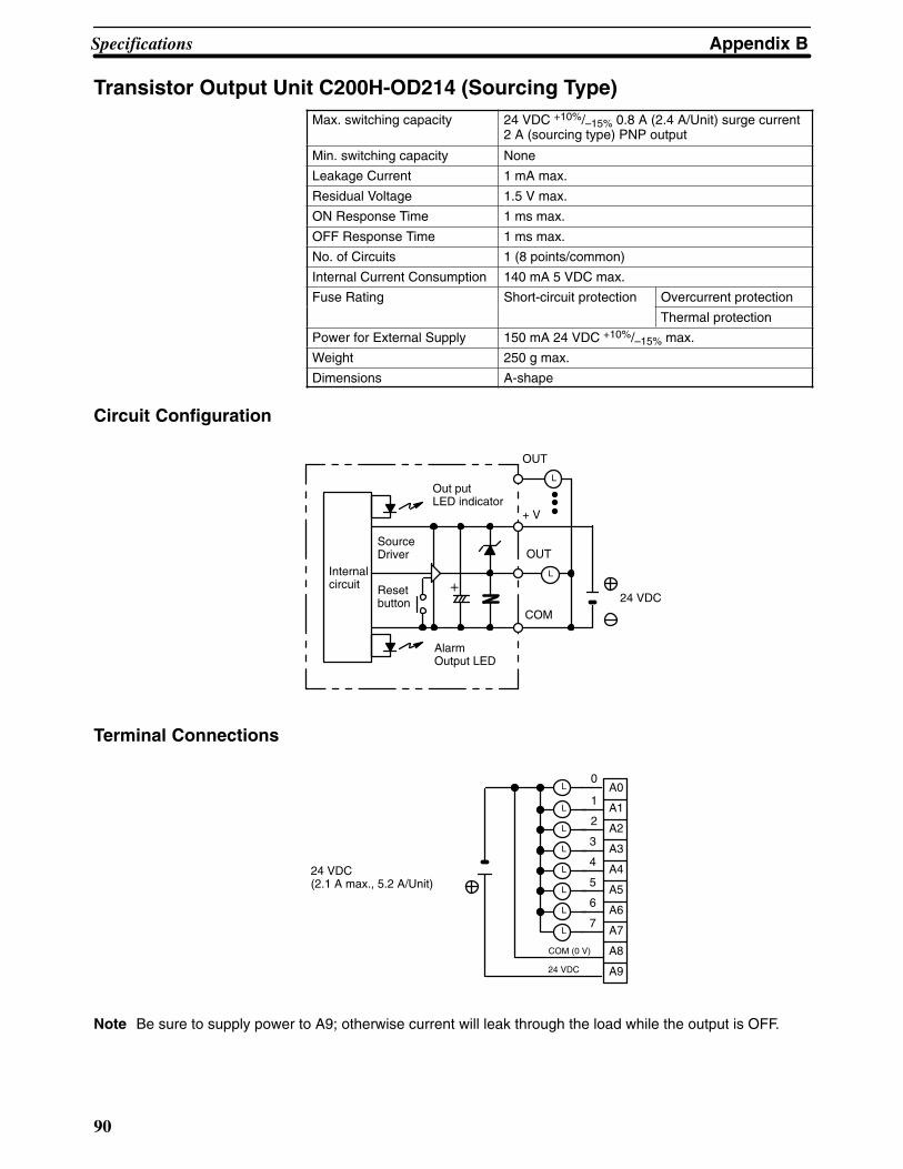
Appendix BSpecifications
90
Transistor Output Unit C200H-OD214 (Sourcing Type)Max. switching capacity 24 VDC +10%/–15% 0.8 A (2.4 A/Unit) surge current
2 A (sourcing type) PNP output
Min. switching capacity None
Leakage Current 1 mA max.
Residual Voltage 1.5 V max.
ON Response Time 1 ms max.
OFF Response Time 1 ms max.
No. of Circuits 1 (8 points/common)
Internal Current Consumption 140 mA 5 VDC max.
Fuse Rating Short-circuit protection Overcurrent protection
Thermal protection
Power for External Supply 150 mA 24 VDC +10%/–15% max.
Weight 250 g max.
Dimensions A-shape
Circuit Configuration
Internalcircuit
COM
OUT
L
+ V
24 VDCResetbutton
SourceDriver
+
AlarmOutput LED
Out put LED indicator
OUT
L
Terminal Connections
L
L
L
L
L
L
L
L
24 VDC (2.1 A max., 5.2 A/Unit)
A0
A1
A2
A3
A4
A5
A6
A7
A8
A9
0
1
2
3
4
5
6
7
COM (0 V)
24 VDC
Note Be sure to supply power to A9; otherwise current will leak through the load while the output is OFF.
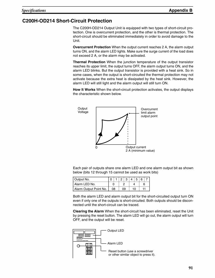
Appendix BSpecifications
91
C200H-OD214 Short-Circuit ProtectionThe C200H-OD214 Output Unit is equipped with two types of short-circuit pro-tection. One is overcurrent protection, and the other is thermal protection. Theshort-circuit should be eliminated immediately in order to avoid damage to theUnit.
Overcurrent Protection When the output current reaches 2 A, the alarm outputturns ON, and the alarm LED lights. Make sure the surge current of the load doesnot exceed 2 A, or the alarm may be activated.
Thermal Protection When the junction temperature of the output transistorreaches its upper limit, the output turns OFF, the alarm output turns ON, and thealarm LED blinks. But the output transistor is provided with a heat sink. So insome cases, when the output is short-circuited the thermal protection may notactivate because the extra heat is dissipated by the heat sink. However, thealarm LED will still light and the alarm output will still turn ON.
How It Works When the short-circuit protection activates, the output displaysthe characteristic shown below.
Overcurrentlimit alarmoutput point
Output current 2 A (minimum value)
0
OutputVoltage
Each pair of outputs share one alarm LED and one alarm output bit as shownbelow (bits 12 through 15 cannot be used as work bits)
Output No. 0 1 2 3 4 5 6 7
Alarm LED No. 0 2 4 6
Alarm Output Point No. 08 09 10 11
Both the alarm LED and alarm output bit for the short-circuited output turn ONeven if only one of the outputs is short-circuited. Both outputs should be discon-nected until the short-circuit can be traced.
Clearing the Alarm When the short-circuit has been eliminated, reset the Unitby pressing the reset button. The alarm LED will go out, the alarm output will turnOFF, and the output will be reset.
Reset button (use a screwdriveror other similar object to press it).
Output LED
Alarm LED

Appendix BSpecifications
92
Programming Example If there is a short-circuit in an output, we want the pro-gram to turn that output OFF. Assume that the Unit is mounted at word 000. Aprogram to turn OFF output bits 00 and 01 is shown below.
00000
00001
A
B
00008
00008
Since alarm output bit 08 covers both output bits 00 and 01, both these outputsare forced OFF as soon as output bit 08 turns ON (bits A and B can be any otherbits required in the program).

Appendix BSpecifications
93
Transistor Output Unit C200H-OD216Max. switching capacity 0.3 A 5 to 24 VDC
Min. switching capacity 10 mA 5 VDC
Leakage Current 0.1 mA max.
Residual Voltage 1.5 V max.
ON Response Time 1.5 ms max.
OFF Response Time 2 ms max.
No. of Circuits 1 (8 points/common) positive common (sourcingtype)
Internal Current Consumption 10 mA 5 VDC max. 75 mA 25 VDC (8 points ONsimultaneously.)
Fuse Rating None
Power for External Supply N/A
Weight 250 g max.
Dimensions A-shape
Circuit Configuration
OutputLED indicator
OUT
OUT
COM
InternalCircuit
5 to 24 VDC
L
L
Terminal Connections
A0
A1
A2
A3
A4
A5
A6
A7
A8
A9
0
1
2
3
4
5
6
7
COM
5 to 24 VDC
NC
L
L
L
L
L
L
L
L

Appendix BSpecifications
94
Transistor Output Unit C200H-OD217Max. switching capacity 0.3 A 5 to 24 VDC
Min. switching capacity 10 mA 5 VDC
Leakage Current 0.1 mA max.
Residual Voltage 1.5 V max.
ON Response Time 1.5 ms max.
OFF Response Time 2 ms max.
No. of Circuits 1 (12 points/common) positive common (sourcingtype)
Internal Current Consumption 10 mA 5 VDC max. 75 mA 25 VDC (8 points ONsimultaneously.)
Fuse Rating None
Power for External Supply N/A
Weight 300 g max.
Dimensions B-shape
Circuit Configuration
Internalcircuit
OutputLED indicator
OUT
OUT
COM
L
L
5 to 24 VDC
Terminal Connections
A0
A1
A2
A3
A4
A5
A6
A7
A8
1
3
5
7
9
11
COM
5 to 24 VDC
NC
B0
B1
B2
B3
B4
B5
B6
B7
B8
B9
NC
NC
NC
NC
NC
0
2
4
6
8
10
L
L
L
L
L
L
L
L
L
L
L
L

Appendix BSpecifications
95
Transistor Output Unit C200H-OD411Max. switching capacity 12 to 48 VDC 1 A (3 A/Unit)
Min. switching capacity None
Leakage Current 0.1 mA max.
Residual Voltage 1.4 V max.
ON Response Time 0.2 ms max.
OFF Response Time 0.3 ms max.
No. of Circuits 1 (8 points/common)
Internal Current Consumption 140 mA 5 VDC max.
Fuse Rating 5 A 125 V (5.2-dia.x20)
Power for External Supply 30 mA 12 to 48 VDC max.
Weight 250 g max.
Dimensions A-shape
Circuit Configuration
Internalcircuit
L
OUT
COM
OUT
L
F LED
Fuse blowoutdetection circuit
V
Fuse
12 to 48 VDC
Output LED indicator
Note When the fuse blows F LED lights and bit 08 turns ON. Bits 08 through 15 cannot be used as work bits.
Terminal Connections
A0
A1
A2
A3
A4
A5
A6
A7
A8
A9
0
1
2
3
4
5
6
7
L
L
L
L
L
L
L
L
COM (0 V)
12 to 48 VDC
12 to 48 VDC(1 A max., 3 A/Unit)
Note Be sure to supply power to A9; otherwise current will leak through the load while the output is OFF.
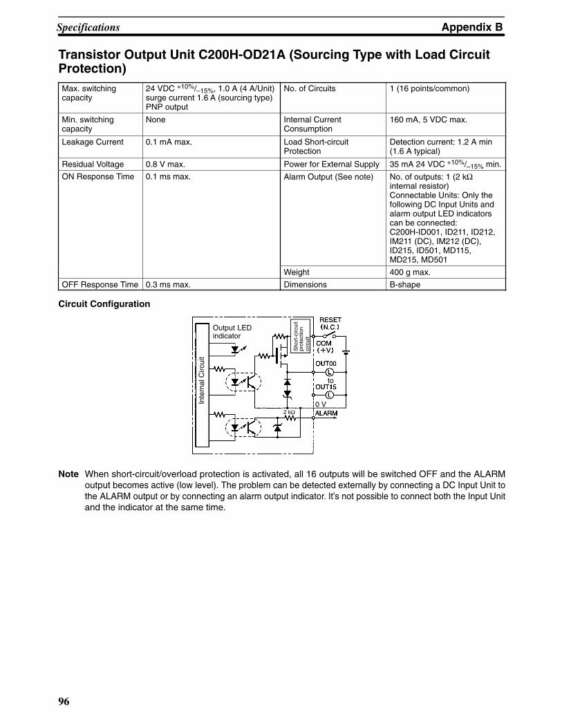
Appendix BSpecifications
96
Transistor Output Unit C200H-OD21A (Sourcing Type with Load CircuitProtection)Max. switchingcapacity
24 VDC +10%/–15%, 1.0 A (4 A/Unit)surge current 1.6 A (sourcing type)PNP output
No. of Circuits 1 (16 points/common)
Min. switchingcapacity
None Internal CurrentConsumption
160 mA, 5 VDC max.
Leakage Current 0.1 mA max. Load Short-circuitProtection
Detection current: 1.2 A min (1.6 A typical)
Residual Voltage 0.8 V max. Power for External Supply 35 mA 24 VDC +10%/–15% min.
ON Response Time 0.1 ms max. Alarm Output (See note) No. of outputs: 1 (2 kΩinternal resistor)Connectable Units: Only thefollowing DC Input Units andalarm output LED indicatorscan be connected:C200H-ID001, ID211, ID212,IM211 (DC), IM212 (DC),ID215, ID501, MD115,MD215, MD501
Weight 400 g max.
OFF Response Time 0.3 ms max. Dimensions B-shape
Circuit Configuration
Inte
rnal
Circ
uit
Output LEDindicator
0 V2 kΩ
to
Sho
rt-c
ircui
tpr
otec
tion
circ
uit
Note When short-circuit/overload protection is activated, all 16 outputs will be switched OFF and the ALARMoutput becomes active (low level). The problem can be detected externally by connecting a DC Input Unit tothe ALARM output or by connecting an alarm output indicator. It’s not possible to connect both the Input Unitand the indicator at the same time.

Appendix BSpecifications
97
Terminal Connections
+24 VDC
24 VDC
Note 1. When the ALARM output turns ON, remove the cause of the high current and then shut off the externalpower supply for approx. 1 second. After confirming that the cause has been removed, turn ON the pow-er supply again to reset the output. As shown in the diagram, it is recommended that a relay or switch thatturns ON or OFF only the external power supply be connected right before the B9 (+V). Check that thisrelay or switch has a contact capacity higher than the external power supply current consumption(35 mA + load current min.).
2. This Unit must be mounted to a C200H-BC��1-V1/V2 Backplane.
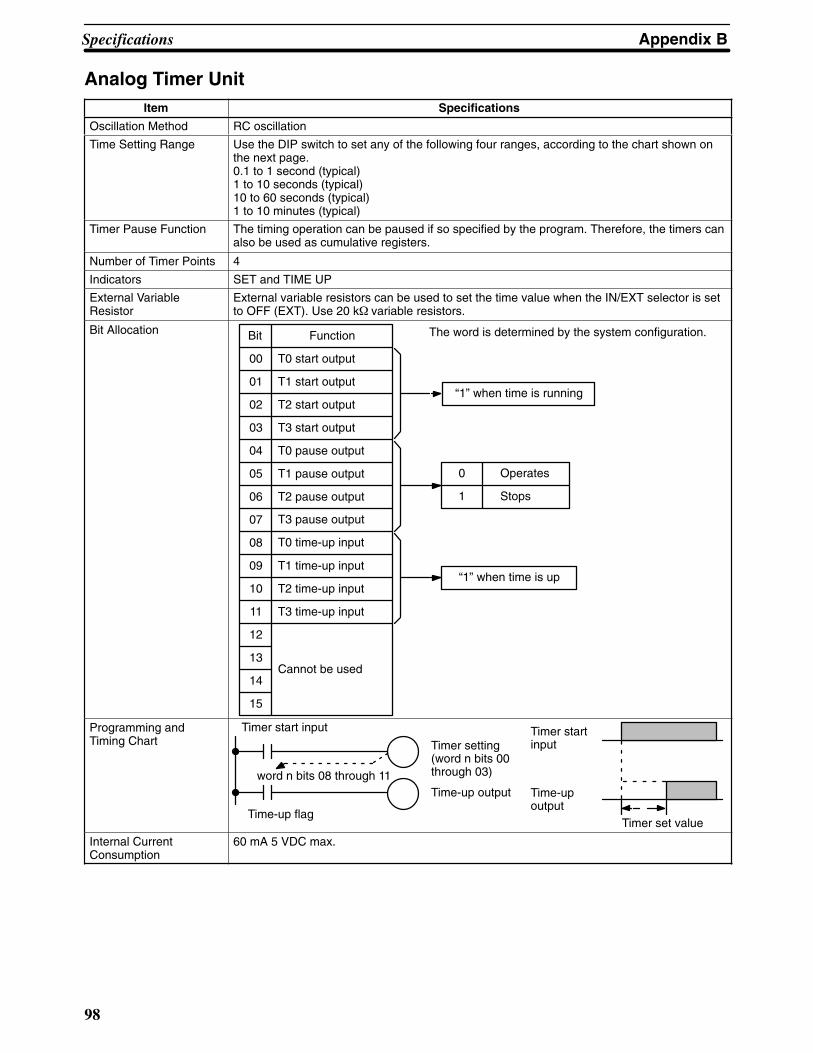
Appendix BSpecifications
98
Analog Timer UnitItem Specifications
Oscillation Method RC oscillation
Time Setting Range Use the DIP switch to set any of the following four ranges, according to the chart shown onthe next page.0.1 to 1 second (typical)1 to 10 seconds (typical)10 to 60 seconds (typical)1 to 10 minutes (typical)
Timer Pause Function The timing operation can be paused if so specified by the program. Therefore, the timers canalso be used as cumulative registers.
Number of Timer Points 4
Indicators SET and TIME UP
External VariableResistor
External variable resistors can be used to set the time value when the IN/EXT selector is setto OFF (EXT). Use 20 k� variable resistors.
Bit Allocation Function
T0 start output
T1 start output
T2 start output
T3 start output
T0 pause output
T1 pause output
T2 pause output
T3 pause output
T0 time-up input
T1 time-up input
T2 time-up input
T3 time-up input
Cannot be used
Bit
00
01
02
03
04
05
06
07
08
09
10
11
12
13
14
15
“1” when time is running
0
1
Operates
Stops
“1” when time is up
The word is determined by the system configuration.
Programming andTiming Chart
Timer start input
word n bits 08 through 11
Time-up flag
Time-up output
Timer setting(word n bits 00through 03)
Timer startinput
Time-up output
Timer set value
Internal CurrentConsumption
60 mA 5 VDC max.
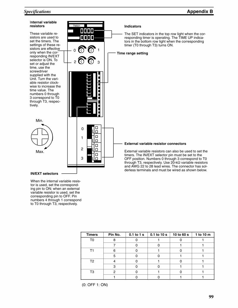
Appendix BSpecifications
99
TM001
0
1
2
3
0 1
2 3
Min.
Max.
Internal variableresistors
These variable re-sistors are used toset the timers. Thesettings of these re-sistors are effectiveonly when the cor-responding IN/EXTselector is ON. Toset or adjust thetime, use thescrewdriversupplied with theUnit. Turn the vari-able resistor clock-wise to increase thetime value. Thenumbers 0 through3 correspond to T0through T3, respec-tively.
Indicators
The SET indicators in the top row light when the cor-responding timer is operating. The TIME UP indica-tors in the bottom row light when the correspondingtimer (T0 through T3) turns ON.
Time range setting
External variable resistor connectors
External variable resistors can also be used to set thetimers. The IN/EXT selector pin must be set to theOFF position. Numbers 0 through 3 correspond to T0through T3, respectively. Use 20-k� variable resistorsand AWG 22 to 28 lead wires. The connector has sol-derless terminals and must be wired as shown below.
IN/EXT selectors
When the internal variable resis-tor is used, set the correspond-ing pin to ON; when an externalvariable resistor is used, set thecorresponding pin to OFF. Pinnumbers 4 through 1 correspondto T0 through T3, respectively.
Timers Pin No. 0.1 to 1 s 0.1 to 10 s 10 to 60 s 1 to 10 m
T0 8 0 1 0 1
7 0 0 1 1
T1 6 0 1 0 1
5 0 0 1 1
T2 4 0 1 0 1
3 0 0 1 1
T3 2 0 1 0 1
1 0 0 1 1
(0: OFF 1: ON)

!
Appendix BSpecifications
100
Caution Ensure that the external variable resistor connectors are open when using the internal variableresistor.
External variableresistor connector
External variableresistor
B7A Interface Unit C200H-B7A�1 (Basic I/O Unit Type)The B7A Interface Unit used with the B7A Link Terminal allows the transmission and reception of 16-point I/O dataover two wires.
The following B7A Interface Unit and B7A Link Terminal models are available.
B7A Interface Unit B7A Link Terminals
16-point input: C200H-B7AI1 B7A-T6�1 (Screw terminal models)B7A-T6D2 (Modular models)
16-point output: C200H-B7AO1 B7A-R6��1 (Screw terminal models)B7A-R6A52 (Modular models)
Mount the B7A Interface Unit to the C200H-BC��1-V1 or C200H-BC��1-V2 Backplane.
Note If the B7A Interface Unit is connected to the C200H-CPU03-E or C200H-PS211, supply 24 VDC from anindependent power supply to the B7A Interface Unit or use a transformer to separate the power supply lineto the B7A Interface Unit from the power supply lines to the CPU and I/O Power Supply Unit.
12 to 24 VDC
I/O indicator
Connection terminals for the B7A Link Terminal:
Connect this terminal to the SIG terminal of theB7A Link Terminal.
Connect this terminal to the negative power ter-minal of the B7A Link Terminal.
Supply 12 to 24 VDC.
ERR indicator
Connection terminals
I/O IndicatorIndicates the ON or OFF status of input from the B7A Link Terminal or the ONand OFF status of output to the B7A Link Terminal.ERR IndicatorIncorporated by the B7AI1 and lit when the B7AI1’s data transmission or recep-tion is abnormal.

!
Appendix BSpecifications
101
Connection TerminalsSIG: Connects to the SIG terminal of the B7A Link Terminal.V–: Connects to the negative power terminal of the B7A Link Terminal.
Caution If the terminals are not connected correctly, the internal circuitry of the B7A Link Terminal will bedamaged.
Note 1. The transmission cable must be a VCTF cable with a thickness of 0.75 mm2 minimum.
2. Do not wire power lines or high-tension lines along with the transmission cable in the same conduit.
Input Mode SelectorThe B7AI1 incorporates an input mode selector on the back panel of the Unit,with which the following modes can be set.
Input mode 15 points + 1 error 16 points
Function Fifteen-point input from the B7A LinkTerminal is effective. Bit 15 is used astransmission error bit.
Sixteen-point input from the B7A LinkTerminal is effective.
Switch setting Upper side Lower side
Bit no.ll i
00 to 14 Input 00 to input 14 Input 00 to input 14allocation 15 Transmission error bit Input 15
Status of input indicator lamp 15 Not used Lit when input 15 is ON. Not lit wheninput 15 is OFF.
Status of the ERR indicator Lit when there is a transmission error and OFF during normal transmission
The ERR indicator is lit when an error occurs. If the error is corrected, the ERR indicator is OFF at the next trans-mission cycle.
When there is a transmission error, the B7A Link Terminal will hold the data just before the occurrence of the trans-mission error. If there is a transmission error because the B7A Link Terminal is turned off, however, data 0 is trans-mitted in the first transmission cycle when the B7A Link Terminal is turned on again.
Transmission errors between the C200H-B7A01 and B7A Link Terminal are detected by the B7A Link Terminalonly. Check the ERR indicator and error bit for any error.
Performance Specification
Item C200H-B7AI1 C200H-B7AO1
I/O points 16 points or 15 points and 1 errorinput
16 output points
Transmission distance 500 m max. if power is supplied to the Interface Unit and B7A Link Terminalseparately.100 m max. if power is supplied to the Interface Unit and B7A Link Terminalfrom a single power supply.
Transmission delay Typ. 19.2 ms, 31 ms max.
Minimum input time (see note 2) --- 16 ms
Internal current consumption 5 VDC, 100 mA max.
External power supply (see note 1) 12 to 24 VDC ±10%, 10 mA min. 12 to 24 VDC ±10%, 30 mA min.
Weight 200 g max.
Note 1. The external power supply capacity does not include the capacity required by the B7A Link Terminal.
2. The minimum input time is the minimum time required to read input signals from the CPU. Be sure thatthe ON/OFF width of signals sent to B7A Interface Unit output relays is at least 16 ms.

Appendix BSpecifications
102
DimensionsRacksThe dimensions shown below are for both the CPU Rack and Expansion I/O Rack. The C dimension for the Pro-gramming Console will increase by 30mm when the Programming Console Adapter C200H-BP001 is used, andwill increase by 50 mm when the Programming Console Adapter C200H-BP002 is used.
130 118
AW
7.56.5
M-4screws
505491
270.5
C200H-BC101
Model A W
C200H-BC031 246 260
C200H-BC051-V1 316 330
C200H-BC081-V1 421 435
C200H-BC101 491 505
135
DC
Peripheraldevice
CPU Unit D
C200H-CPU01/02/03 118
C200H-CPU11 143

Appendix BSpecifications
103
Mounted Unit C
CPU01/03 CPU11
Programming Console 148 173
Other peripheral devices 160 185
B-shape I/O Units 145 145
E-shape I/O Units 138 138
I/O Units The dimensions shown below are for the three shapes of I/O Units mentioned throughout these specifications.
x
x
101
118
xx
35
130 Back-plane
A-shape I/O Units
145
128
Back-plane
xx
xx
xx
xx
35
130
B-shape I/O Units

Appendix BSpecifications
104
138
121
x
x
xx
35
130
E-shape I/O Units
Bac
kpla
ne
Backplane Insulation PlatesThe dimensions shown below are for Backplane Insulation Plates.
135 118 110
DA
E
Insulation plate mounting screwsFour screws with 5-mm diametershafts are provided.
PC mounting screwsFour screws with 4-mm diameterheads are provided.
12 dia
10
6
5 dia
B
C
Specifications Model D E C A B
3 slots C200H-ATT31 210 261 --- 246 ---
5 slots C200H-ATT51 280 331 --- 316 ---
8 slots C200H-ATT81 385 436 --- 421 ---
10 slots C200H-ATTA1 455 506 227.5 491 270.5
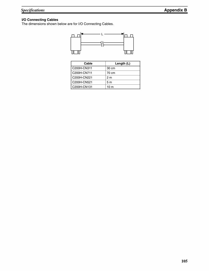
Appendix BSpecifications
105
I/O Connecting CablesThe dimensions shown below are for I/O Connecting Cables.
L
Cable Length (L)
C200H-CN311 30 cm
C200H-CN711 70 cm
C200H-CN221 2 m
C200H-CN521 5 m
C200H-CN131 10 m

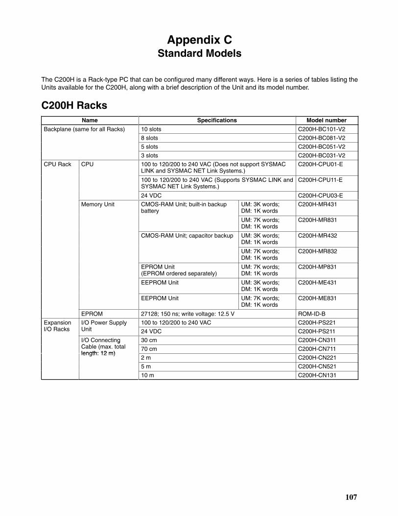
107
Appendix CStandard Models
The C200H is a Rack-type PC that can be configured many different ways. Here is a series of tables listing theUnits available for the C200H, along with a brief description of the Unit and its model number.
C200H RacksName Specifications Model number
Backplane (same for all Racks) 10 slots C200H-BC101-V2
8 slots C200H-BC081-V2
5 slots C200H-BC051-V2
3 slots C200H-BC031-V2
CPU Rack CPU 100 to 120/200 to 240 VAC (Does not support SYSMACLINK and SYSMAC NET Link Systems.)
C200H-CPU01-E
100 to 120/200 to 240 VAC (Supports SYSMAC LINK andSYSMAC NET Link Systems.)
C200H-CPU11-E
24 VDC C200H-CPU03-E
Memory Unit CMOS-RAM Unit; built-in backupbattery
UM: 3K words; DM: 1K words
C200H-MR431
UM: 7K words; DM: 1K words
C200H-MR831
CMOS-RAM Unit; capacitor backup UM: 3K words; DM: 1K words
C200H-MR432
UM: 7K words; DM: 1K words
C200H-MR832
EPROM Unit (EPROM ordered separately)
UM: 7K words; DM: 1K words
C200H-MP831
EEPROM Unit UM: 3K words; DM: 1K words
C200H-ME431
EEPROM Unit UM: 7K words; DM: 1K words
C200H-ME831
EPROM 27128; 150 ns; write voltage: 12.5 V ROM-ID-B
ExpansionI/O R k
I/O Power SupplyU i
100 to 120/200 to 240 VAC C200H-PS221I/O Racks
yUnit 24 VDC C200H-PS211
I/O ConnectingC bl ( l
30 cm C200H-CN311gCable (max. totallength: 12 m)
70 cm C200H-CN711length: 12 m)
2 m C200H-CN221
5 m C200H-CN521
10 m C200H-CN131

Appendix CStandard Models
108
C200H I/O UnitsName Specifications Model number
Input Units AC Input Unit 8 pts 100 to 120 VAC C200H-IA121
16 pts 100 to 120 VAC C200H-IA122/IA122V
8 pts 200 to 240 VAC C200H-IA221
16 pts 200 to 240 VAC C200H-IA222/IA222V
DC Input Unit 8 pts No-voltage contact; NPN C200H-ID001
8 pts No-voltage contact; PNP C200H-ID002
8 pts 12 to 24 VDC C200H-ID211
16 pts 24 VDC C200H-ID212
AC/DC Input Unit 8 pts 12 to 24 VAC/DC C200H-IM211
16 pts 24 VAC/DC C200H-IM212
OutputU i
Relay Output Unit 8 pts 2 A, 250 VAC/24 VDC (For resistive loads) C200H-OC221Units 12 pts 2 A, 250 VAC/24 VDC (For resistive loads) C200H-OC222
16 pts 2 A, 250 VAC/24 VAC (For resistive loads) C200H-OC225
5 pts 2 A, 250 VAC/24 VDC (For resistive loads)Independent commons
C200H-OC223
8 pts 2 A, 250 VAC/24 VDC (For resistive loads)Independent commons
C200H-OC224
Triac Output Unit 8 pts 1 A, 120 VAC C200H-OA121-E
8 pts 1.2 A, 120 VAC C200H-OA122-E
8 pts 1.2 A, 250 VAC C200H-OA223
12 pts 0.3 A, 250 VAC C200H-OA222V
12 pts 0.5 A, 250 VAC C200H-OA224
Transistor OutputU i
8 pts 1 A, 12 to 48 VDC C200H-OD411Unit 12 pts 0.3 A, 24 VDC C200H-OD211
16 pts 0.3 A, 24 VDC C200H-OD212
8 pts 2.1 A, 24 VDC C200H-OD213
8 pts 0.8 A, 24 VDC; sourcing type (PNP); withload short protection
C200H-OD214
8 pts 5 to 24 VDC; sourcing type (PNP) C200H-OD216
12 pts 5 to 24 VDC; sourcing type (PNP) C200H-OD217
16 pts 1 A, 24 VDC; sourcing type (PNP); with loadshort protection
C200H-OD21A
Analog Timer Unit 4 timerpts
0.1 to 1 s, 1 to 10 s, 10 to 60 s, or 1 min to10 min (switchable)
C200H-TM001
Variable ResistorConnector (RelatedProduct)
Connector with lead wire (2 m) for 1 externalresistor
C4K-CN223
B7A Interface Units (Basic I/O Units)
15 or16 inputpts
Connects to B7A Link Terminals. C200H-B7AI1
16 out-put pts
C200H-B7AO1
Note The C200H-OC225/OD212/OD21A 16-point Output Unit and the C200H-B7AO1 B7A Interface Unit mustbe mounted to a C200H-BC��1-V1/V2 Backplane.

Appendix CStandard Models
109
C200H Special I/O UnitsAll of the following are classified as Special I/O Units except for the ASCII Unit, which is an Intelligent I/O Unit.
Name Specifications Model number
High-den-sity I/OUnits
DC InputUnits
32 pts 5 VDC (TTL inputs); with high-speed input function C200H-ID501
32 pts 24 VDC; with high-speed inputs C200H-ID215
TransistorOutput Units
32 pts 0.1 A, 24 VDC (usable as 128-point dynamic outputunit)
C200H-OD215
32 pts 35 mA, 5 VDC (TTL outputs) (usable as 128-pointdynamic output unit)
C200H-OD501
DC Input/TransistorOutput Units
16 input/16 output pts
12-VDC inputs; with high-speed input function0.1 A , 12-VDC outputs (usable as 128-point dynam-ic input unit)
C200H-MD115
16 input/16 output pts
24-VDC inputs; with high-speed input function0.1 A , 24-VDC outputs (usable as 128-point dynam-ic input unit)
C200H-MD215
16 input/16 output pts
5 VDC (TTL inputs); with high speed input function35 mA, 5 VDC Output (TTL outputs) (usable as128-point dynamic input unit)
C200H-MD501
Analog I/OUnits
Analog InputUnit
1 to 5/0 to 10 V; 4 inputs C200H-AD001
4 to 20 mA, 1 to 5/0 to 10/–10 to 10 V; 8 inputs C200H-AD002
Analog OutputU i
1 to 5/0 to 10 V; 2 outputs C200H-DA001gUnit 4 to 20 mA, –10 to 10 V; 4 outputs C200H-DA002
Temperature Sensor Units Thermocouple (K(CA) or J(IC)) (switchable); 4 inputs C200H-TS001
Thermocouple (K(CA) or L(Fe-CuNi)) (switchable);4 inputs
C200H-TS002
Platinum resistance thermometer (JPt) (switchable), DIN stan-dards; 4 inputs
C200H-TS101
Platinum resistance thermometer (Pt) (switchable);4 inputs
C200H-TS102
Temperature Control Units Thermocou-l
Transistor output C200H-TC001ple Voltage output C200H-TC002
Current output C200H-TC003
Platinum re-i
Transistor output C200H-TC101sistancethermometer
Voltage output C200H-TC102thermometer
Current output C200H-TC103
Heat/Cool TemperatureC l U i
Thermocou-l
Transistor output C200H-TV001Control Units ple Voltage output C200H-TV002
Current output C200H-TV003
Platinum re-i
Transistor output C200H-TV101sistancethermometer
Voltage output C200H-TV102thermometer
Current output C200H-TV103
PID Control Units Transistor output C200H-PID01
Voltage output C200H-PID02
Current output C200H-PID03
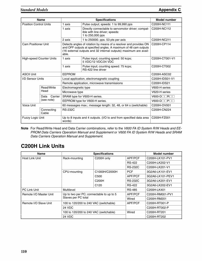
Appendix CStandard Models
110
Name Model numberSpecifications
Position Control Units 1 axis Pulse output; speeds: 1 to 99,990 pps C200H-NC111
1 axis Directly connectable to servomotor driver; compat-ible with line driver; speeds: 1 to 250,000 pps
C200H-NC112
2 axis 1 to 250000. pps. 53 pts per axis C200H-NC211
Cam Positioner Unit Detects angles of rotation by means of a resolver and provides ONand OFF outputs at specified angles. A maximum of 48 cam outputs(16 external outputs and 32 internal outputs) maximum are avail-able.
C200H-CP114
High-speed Counter Units 1 axis Pulse input; counting speed: 50 kcps; 5 VDC/12 VDC/24 VDC
C200H-CT001-V1
1 axis Pulse input; counting speed: 75 kcps; RS-422 line driver
C200H-CT002
ASCII Unit EEPROM C200H-ASC02
I/D Sensor Units Local application, electromagnetic coupling C200H-IDS01-V1
Remote application, microwave transmissions C200H-IDS21
Read/WriteH d
Electromagnetic type V600-H seriesHead Microwave type V620-H series
Data Carrier( )
SRAM type for V600-H series. V600-D��R��
(see note) EEPROM type for V600-H series. V600-D��P��
Voice Unit 60 messages max.; message length: 32, 48, or 64 s (switchable) C200H-OV001
ConnectingCable
RS-232C C200H-CN224
Fuzzy Logic Unit Up to 8 inputs and 4 outputs. (I/O to and from specified data areawords)
C200H-FZ001
Note For Read/Write Head and Data Carrier combinations, refer to the V600 FA ID System R/W Heads and EE-PROM Data Carriers Operation Manual and Supplement or V600 FA ID System R/W Heads and SRAMData Carriers Operation Manual and Supplement.
C200H Link UnitsName Specifications Model number
Host Link Unit Rack-mounting C200H only APF/PCF C200H-LK101-PV1
RS-422 C200H-LK202-V1
RS-232C C200H-LK201-V1
CPU-mounting C1000H/C2000H PCF 3G2A6-LK101-EV1
C500 APF/PCF 3G2A6-LK101-PEV1
C200H RS-232C 3G2A6-LK201-EV1
C120 RS-422 3G2A6-LK202-EV1
PC Link Unit Multilevel RS-485 C200H-LK401
Remote I/O Master Unit Up to two per PC; connectable to up to 5Sl PC l
APF/PCF C200H-RM001-PV1Slaves per PC total Wired C200H-RM201
Remote I/O Slave Unit 100 to 120/200 to 240 VAC (switchable) APF/PCF C200H-RT001-P
24 VDC C200H-RT002-P
100 to 120/200 to 240 VAC (switchable) Wired C200H-RT201
24 VDC C200H-RT202

Appendix CStandard Models
111
Optional Products
Name Specifications Model number
I/O Unit Cover Cover for 10-pin terminal block C200H-COV11
Terminal Block Cover Short protection for 10-pin terminal block C200H-COV02
Short protection for 19-pin terminal block C200H-COV03
Connector Cover Protective cover for unused I/O Connecting Cable connectors C500-COV01
Space Unit Used for vacant slots C200H-SP001
Battery Set For C200H RAM Memory Unit only C200H-BAT09
Relay 24 VDC G6B-1174P-FD-US DC24
Backplane Insulation Plate For 10-slot Backplane C200H-ATTA1
For 8-slot Backplane C200H-ATT81
For 5-slot Backplane C200H-ATT51
For 3-slot Backplane C200H-ATT31
I/O Bracket For 5-slot Backplane C200H-ATT53
For 8-slot Backplane C200H-ATT83
For 3-slot Backplane C200H-ATT33
Memory Unit Lock Fitting To secure Memory Unit to CPU C200H-ATT03
External Connector Solder terminal; 40 pin with connector cover C500-CE401
Solderless terminal; 40 pin with connector cover (crimp-type) C500-CE402
Pressure welded terminal; 40 pin C500-CE403
Solder terminal; 40 pin with connector cover (right-angle type)
C500-CE404
Solderless terminal; 40 pin with connector cover(right-angle type)
C500-CE405
Solder terminal; 24 pin with connector cover C500-CE241
Solderless terminal; 24 pin with connector cover (crimp-type) C500-CE242
Pressure welded terminal; 24 pin C500-CE243
Optical Units
Name Specifications Model no.
Optical I/O Unit No-voltage Input Unit 8 pts. 100 to 120 VACl
APF/PCF 3G5A2-ID001-PEpower supply PCF 3G5A2-ID001-E
AC/DC Input Unit 12 to 24 VAC/DC 8 pts. APF/PCF 3G5A2-IM211-PE
PCF 3G5A2-IM211-E
AC Input Unit 100 to 120 VAC 8 pts. APF/PCF 3G5A2-IA121-PE
PCF 3G5A2-IA121-E
Relay Output Unit 2A, 250 VAC/24 VDC( / l k ) 8
100 to 120/200 to240 VAC
APF/PCF 3G5A2-OC221-PE,(w/relay socket) 8 pts. 240 VAC power
supplyPCF 3G5A2-OC221-E
Triac Output Unit 1A, 100 to 120/200 to240 VAC (w/built-in
supplyAPF/PCF 3G5A2-OA222-PE
240 VAC (w/built-insurge killer) 8 pts. PCF 3G5A2-OA222-E
Transistor Output Unit 0.3 A, 12 to 48 VDC 8 pts.
APF/PCF 3G5A2-OD411-PE
Repeater Unit Connected between 32nd and 33rd Unitswhen connecting more than 33 Units in a
APF/PCF 3G5A2-RPT01-PEwhen connecting more than 33 Units in aRemote Subsystem; power supply: 85 to250 VAC.
PCF 3G5A2-RPT01-E

Appendix CStandard Models
112
Link AdaptersName Specifications Model no.
Link Adapter 3 RS-422 connectors 3G2A9-AL001
3 optical connectors (APF/PCF) 3G2A9-AL002-PE
3 optical connectors (PCF) 3G2A9-AL002-E
1 connector for RS-232C; 2 for RS-422 3G2A9-AL003
1 connector each for APF/PCF, RS-422, and RS-232C 3G2A9-AL004-PE
1 connector each for PCF, RS-422, and RS-232C 3G2A9-AL004-E
1 connector each for APF/PCF and APF 3G2A9-AL005-PE
1 connector each for PCF and AGF 3G2A9-AL005-E
1 connector for APF/PCF; 2 for AGF 3G2A9-AL006-PE
1 connector for PCF; 2 for AGF 3G2A9-AL006-E
O/E converter; 1 connector for RS-485, 1 connector each for APF/PCF B500-AL007-PE
Used for on-line removal of FIT or SYSMAC NET Link Units from theSYSMAC NET Link System, SYSMAC NET Optical Link Adapter 3connectors for APF/PCF.
B700-AL001
DIN ProductsName Specifications Model number
DIN Track Mounting Bracket 1 set (1 included) C200H-DIN01
DIN Track Length: 50 cm; height: 7.3 cm PFP-50N
Length: 1 m; height: 7.3 cm PFP-100N
Length: 1 m; height: 16 mm PFP-100N2
Optical Fiber CablePlastic Optical Fiber Cable (APF) APF stands for “All-Plastic Fiber”. This cablecan be used to connect only Units having the suffix “-P” in their model number.The maximum length is 20 m. The 3G5A2-PF002 cable comes without connec-tors and must be assembled by the user.
Product Description Model no.
Plastic Optical Fiber Cable Cable only (optical connectors not provided) Order in units of 5 m for cable less than 100 m, or in units of200 m or 500 m.
3G5A2-PF002
Optical Connector A 2 pcs (brown),for plastic Optical fiber 10 m long max. 3G5A2-CO001
Optical Connector B 2 pcs (black) for plastic Optical fiber 8 to 20 m long 3G5A2-CO002
Plastic Optical Fiber Cable 1 m, w/optical connector A provided at both ends 3G5A2-PF101

Appendix CStandard Models
113
Plastic-Clad Optical Fiber Cable (PCF) PCF stands for “Plastic-Clad Fiber”.This cable can be used to connect any Units. The maximum length for Units hav-ing the suffix “-P” in their model number is 200 m. The maximum length for Unitswithout the suffix “-P” in their model number is 800 m.
Product Description Model no.Optical Fiber Cable(f i d )
0.1 m, w/connector Ambient temperature: –10° to 70°C 3G5A2-OF011(for indoors) 1 m, w/connector 3G5A2-OF101
2 m, w/connector 3G5A2-OF201
3 m, w/connector 3G5A2-OF301
5 m, w/connector 3G5A2-OF501
10 m, w/connector 3G5A2-OF111
20 m, w/connector 3G5A2-OF211
30 m, w/connector 3G5A2-OF311
40 m, w/connector 3G5A2-OF411
50 m, w/connector 3G5A2-OF511
Optical Fiber Cable(f d )
1 to 500 m (Order in Units of 10 m) Ambient temperature: –10° to 70°C 3G5A2-OF002(for outdoors) 501 to 800 m (Order in Units of 10 m) Ambient temperature: 0° to 55°C
(Must not be subjected to directsunlight)
Crystal Optical Fiber Cable (AGF) AGF stands for “All-Glass Fiber”. Crystaloptical fiber cable is not available from OMRON.
Cable LengthThe connectors may be difficult to attach to the cables. Therefore, always leavea little extra length when cutting the cable. The lengths given for pre-assembledcables are as shown below.
Fiber length (m)
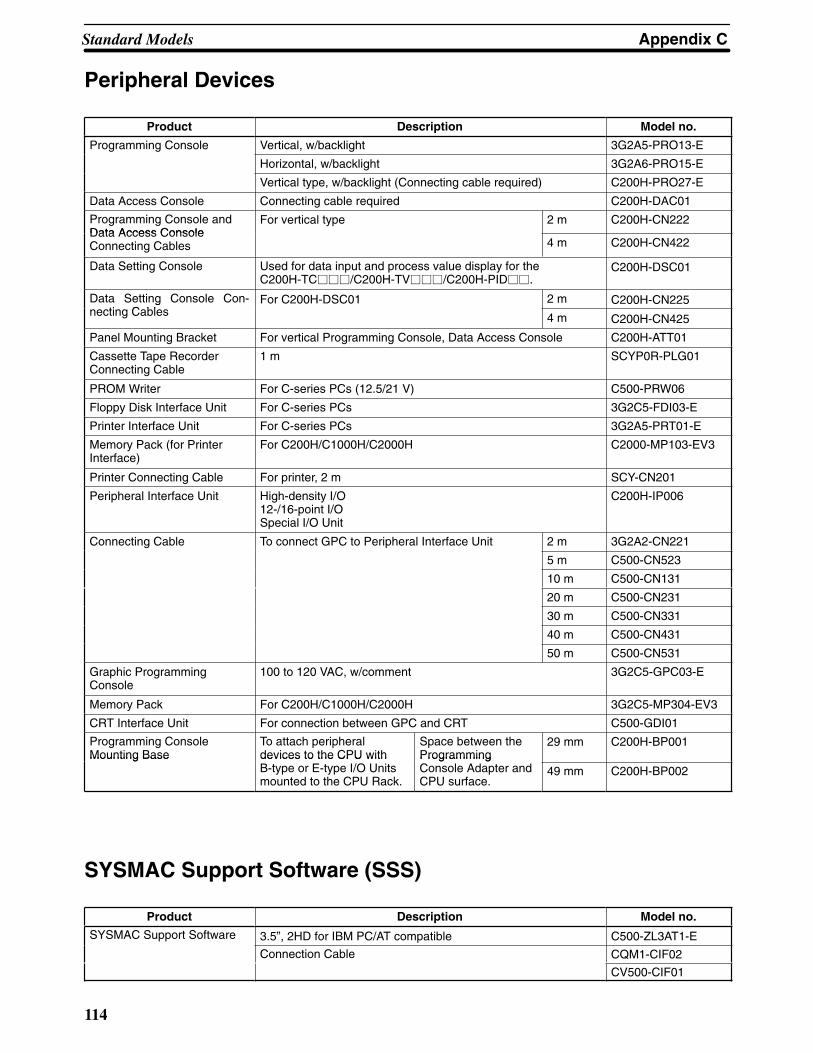
Appendix CStandard Models
114
Peripheral Devices
Product Description Model no.
Programming Console Vertical, w/backlight 3G2A5-PRO13-E
Horizontal, w/backlight 3G2A6-PRO15-E
Vertical type, w/backlight (Connecting cable required) C200H-PRO27-E
Data Access Console Connecting cable required C200H-DAC01
Programming Console andData Access Console
For vertical type 2 m C200H-CN222Data Access ConsoleConnecting Cables 4 m C200H-CN422
Data Setting Console Used for data input and process value display for theC200H-TC���/C200H-TV���/C200H-PID��.
C200H-DSC01
Data Setting Console Con-ti C bl
For C200H-DSC01 2 m C200H-CN225gnecting Cables 4 m C200H-CN425
Panel Mounting Bracket For vertical Programming Console, Data Access Console C200H-ATT01
Cassette Tape RecorderConnecting Cable
1 m SCYP0R-PLG01
PROM Writer For C-series PCs (12.5/21 V) C500-PRW06
Floppy Disk Interface Unit For C-series PCs 3G2C5-FDI03-E
Printer Interface Unit For C-series PCs 3G2A5-PRT01-E
Memory Pack (for PrinterInterface)
For C200H/C1000H/C2000H C2000-MP103-EV3
Printer Connecting Cable For printer, 2 m SCY-CN201
Peripheral Interface Unit High-density I/O12-/16-point I/OSpecial I/O Unit
C200H-IP006
Connecting Cable To connect GPC to Peripheral Interface Unit 2 m 3G2A2-CN221
5 m C500-CN523
10 m C500-CN131
20 m C500-CN231
30 m C500-CN331
40 m C500-CN431
50 m C500-CN531
Graphic ProgrammingConsole
100 to 120 VAC, w/comment 3G2C5-GPC03-E
Memory Pack For C200H/C1000H/C2000H 3G2C5-MP304-EV3
CRT Interface Unit For connection between GPC and CRT C500-GDI01
Programming ConsoleMounting Base
To attach peripheraldevices to the CPU with
Space between theProgramming
29 mm C200H-BP001Mounting Base devices to the CPU with
B-type or E-type I/O Unitsmounted to the CPU Rack.
ProgrammingConsole Adapter andCPU surface.
49 mm C200H-BP002
SYSMAC Support Software (SSS)
Product Description Model no.
SYSMAC Support Software 3.5”, 2HD for IBM PC/AT compatible C500-ZL3AT1-E
Connection Cable CQM1-CIF02
CV500-CIF01

Appendix CStandard Models
115
SYSMAC LINK Unit/SYSMAC NET Link UnitIf you are using any of the Units listed in the table below, they must be mounted toa CPU Rack that uses model C200H-CPU11-E as the CPU. Otherwise, theseUnits will not operate properly.
Name Specifications Model number
SYSMAC LINK Unit Wired via coaxial cable.Must be mounted to leftmost 2 slots on Rack
ith C200H CPU11 E
918 datalink words
C200HW-SLK23
with C200H-CPU11-E 2,966 datalink words
C200HW-SLK24
Wired via optical fiber cable.Bus Connection Unit required separately. Mayb d ith APS P S l U it
918 datalink words
C200HW-SLK13q y y
be used with APS Power Supply Unit. 2,966 datalink words
C200HW-SLK14
Terminator One required for each node at ends of System C1000H-TER01
Attachment Stirrup Provided with SYSMAC LINK Unit C200H-TL001
F Adapter --- C1000H-CE001
F Adapter Cover --- C1000H-COV01
CommunicationsC bl
Coaxial cables Manufactured by Hitachi ECXF5C-2VCable Manufactured by Fujigura 5C-2V
Auxiliary Power Sup-ply Unit
For use with the C200H-SLK13/SLK14 C200H-APS03
SYSMAC NET Link Unit Must be mounted to leftmost 2 slots on Rack withC200H-CPU11-E
C200HS-SNT32
Power SupplyAd
Required when supplying power from CentralP S l
For 1 Unit C200H-APS01yAdapter
q y gPower Supply For 2 Units C200H-APS02
Power Cable Connects Power Supply Adapter and SYS-MAC NET Li k U i
For 1 Unit C200H-CN111yMAC NET Link Unit For 2 Units C200H-CN211
Bus Connection Unit Connects SYSMAC LINK Unit or SYSMACNET Li k U i CPU
For 1 Unit C200H-CE001NET Link Unit to CPU For 2 Units C200H-CE002


117
Appendix DProgramming Console Operation
System OperationsOperation Mode Key Sequence
RUN MON. PROG.
Data AllClear
NO NO YES PLAY
SETNOT
REC
RESETMONTR
HR
DM
CNT
CLR
[Address]
Retained ifpressed
PartialClear
All Clear
I/O TableRegister
NO NO YESCLR FUN SHIFT
*CH B D
79 1 3 WRITECHG
I/O TableVerify
YES YES YESCLR FUN SHIFT
*CH
VER VER
I/O TableRead
YES YES YES
MONTR SHIFT
SHIFT
CLR FUN*
CHSHIFT
[0-7]
Rack no. Unit no.
[0-7]
SettingAddress
YES YES YESCLR [Address]
ErrorMessageRead
YES YES YESMONTRCLR FUN MONTR

Appendix DProgramming Console Operation
118
Programming OperationsOperation Mode Key Sequence
RUN MON. PROG.
SettingAddress
YES YES YES
[Address]CLR
ProgramRead
YES YES YES Addresscurrentlydisplayed
Search YES YES YES
HR
CNT
CLR [Instruction] SRCH SRCH
CLR SHIFTCONT
#
SHIFT
LR
HR
TIM
[Address]
SRCH SRCH
(AR)
CLR
InstructionInsert andInstructionDelete
NO NO YES Locateposition in programthen enter
[Instruction] INS
Instructioncurrentlydisplayed
DEL
ProgramCheck
NO NO YESCLR SRCH
B1
C2
A
0 SRCH SRCH
CLR
To check up to END (01)
To abort
(0, 1, 2: check level)

Appendix DProgramming Console Operation
119
Monitoring and Data Change Operations
Operation Mode Key Sequence
RUN MON. PROG.
Monitor YES YES YES
CLR SHIFT
SHIFT
CONT
#
*CH
HR
LR
SHIFT HR
LD
OUT
TIM
CNT
DM
SHIFT CLR
CLR
[Address]
(Monitor Clear)
MONTR
3 WordMonitor
NO NO YES
EXTBit/Hexmonitor in progress
ForcedSet/Reset
NO YES YES PLAY
SET
REC
RESET
SHIFT
SHIFT
PLAY
SET
REC
RESET
NOT
MONTR
PVChange 1
NO YES YES Change or Timer/Countercurrently displayed
WRITECHG [Data]
PVChange 2
NO YES YESB
A
1
0
CHGChange currentlydisplayed in binary
WRITE
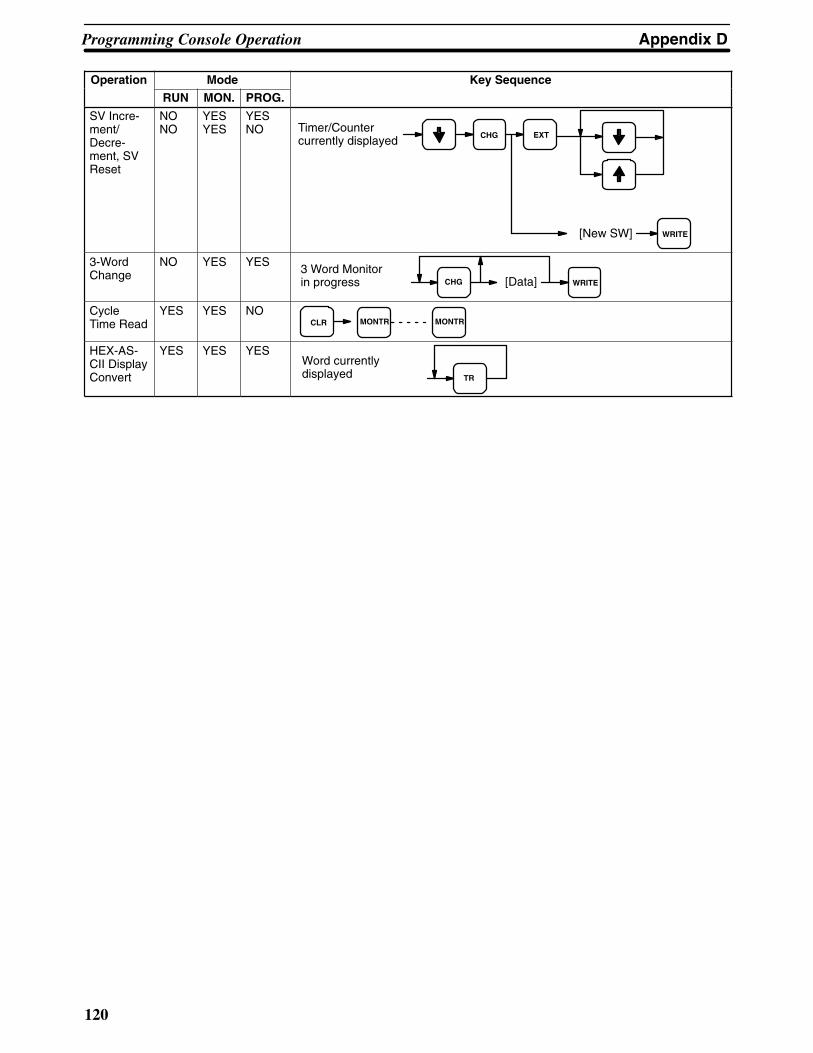
Appendix DProgramming Console Operation
120
Operation Key SequenceMode
PROG.MON.RUN
SV Incre-ment/Decre-ment, SVReset
NONO
YESYES
YESNO Timer/Counter
currently displayedEXTCHG
WRITE[New SW]
3-WordChange
NO YES YES3 Word Monitorin progress CHG WRITE[Data]
CycleTime Read
YES YES NOCLR MONTR MONTR
HEX-AS-CII DisplayConvert
YES YES YESWord currentlydisplayed TR

Appendix DProgramming Console Operation
121
Cassette Tape Operations
OperationMode
RUN MON. PROG.Key Sequence
CLR
NO NO YESCassetteTapeWrite
EXTA
0 [File no.] [Start address]
[Stop address] Start recording with the tape recorder.
Wait for about 5 seconds. (Cancel with the CLR key.)
WRITE
WRITEREC
RESETSHIFT
CassetteTapeRead
CassetteTapeVerify
DM<–>CassetteTape
NO NO YES
NO NO YES
NO NO YES
CLR WRITEEXT [File no.] [Start address]
REC
RESETSHIFTStart tape recorder
playback.
Wait for about 5 seconds.
CLR WRITEEXT [File no.] [Start address]
Wait for about 5 seconds.
VER
CLR EXT
B1 [File no.]
VER
Start tape recorderplayback.
Start tape recorderplayback.
Start tape recorderrecording. SHIFT
5 second tape leader
REC
RESET
PLAY
SETSHIFT
A
0
A
0


123
IR SR HR TR AR LR TC DM #
00000 to 23515 23600 to 25507 HR 0000 to 9915 TR 0 to 7 AR 0000 to 2715 LR 0000 to 6315 TC 000 to 511 Read/Wr: DM 0000 to DM 0999Rd only: DM 1000 to DM 1999
0000 to 9999or 0000 to FFFF
These footnote tables show the actual ranges of all data areas. Bit numbers are provided (except for DM and TC areas); remove the rightmost two digits for word numbers.Data Areas
Appendix EProgramming Instructions
Basic InstructionsName
MnemonicSymbol Function Operand Data Areas
ANDAND B
Logically ANDs the status of the desig-nated bit with the current execution condi-tion.
B:IRSRHRARLRTC
AND LOADAND LD
Logically ANDs the resultant executionconditions of the preceding logic blocks.
None
AND NOTAND NOT
B
Logically ANDs the inverse of the desig-nated bit with the current execution condi-tion.
B:IRSRHRARLRTC
COUNTERCNT
CNT N
SV
CP
R
A decrementing counter. SV: 0 to 9999;CP: count pulse; R: reset input. The TC bitis entered as a constant.
N:TC
SV:IRHRARLRDM#
LOADLD
B
Defines the status of bit B as the executioncondition for subsequent operations in theinstruction line.
B:IRSRHRARLRTCTR
LOAD NOTLD NOT
B
Defines the status of the inverse of bit B asthe execution condition for subsequent op-erations in the instruction line.
B:IRSRHRARLRTC

Appendix EProgramming Instructions
124
IR SR HR TR AR LR TC DM #
00000 to 23515 23600 to 25507 HR 0000 to 9915 TR 0 to 7 AR 0000 to 2715 LR 0000 to 6315 TC 000 to 511 Read/Wr: DM 0000 to DM 0999Rd only: DM 1000 to DM 1999
0000 to 9999or 0000 to FFFF
These footnote tables show the actual ranges of all data areas. Bit numbers are provided (except for DM and TC areas); remove the rightmost two digits for word numbers.Data Areas
NameMnemonic
Operand Data AreasFunctionSymbol
OROR
B
Logically ORs the status of the designatedbit with the current execution condition.
B:IRSRHRARLRTC
OR LOADOR LD
Logically ORs the resultant execution con-ditions of the preceding logic blocks.
None
OR NOTOR NOT
B
Logically ORs the inverse of the desig-nated bit with the execution condition.
B:IRSRHRARLRTC
OUTPUTOUT
B
Turns ON B for an ON execution condition;turns OFF B for an OFF execution condi-tion.
B:IRSRHRARLRTR
OUTPUT NOTOUT NOT
B
Turns OFF B for an ON execution condi-tion; turns ON B for an OFF execution con-dition.
B:IRSRHRARLR
TIMERTIM
TIM N
SV
ON-delay (decrementing) timer operation.Set value: 000.0 to 999.9 s. The same TCbit cannot be assigned to more than onetimer/counter. The TC bit is entered as aconstant.
N:TC
SV:IRHRARLRDM#
Special Instructions
NameMnemonic
Symbol Function Operand Data Areas
NO OPERATIONNOP(00)
None
Nothing is executed and program opera-tion moves to the next instruction.
None

Appendix EProgramming Instructions
125
IR SR HR TR AR LR TC DM #
00000 to 23515 23600 to 25507 HR 0000 to 9915 TR 0 to 7 AR 0000 to 2715 LR 0000 to 6315 TC 000 to 511 Read/Wr: DM 0000 to DM 0999Rd only: DM 1000 to DM 1999
0000 to 9999or 0000 to FFFF
These footnote tables show the actual ranges of all data areas. Bit numbers are provided (except for DM and TC areas); remove the rightmost two digits for word numbers.Data Areas
NameMnemonic
Operand Data AreasFunctionSymbol
ENDEND(01)
END(01)
Required at the end of each program. In-structions located after END(01) will not beexecuted.
None
INTERLOCKIL(02)INTERLOCK CLEARILC(03)
IL(02)
ILC(03)
If an interlock condition is OFF, all outputsand all timer PVs between the currentIL(02) and the next ILC(03) are turned OFFor reset, respectively. Other instructionsare treated as NOP. Counter PVs are main-tained. If the execution condition is ON, ex-ecution continues normally.
None
JUMPJMP(04)JUMP ENDJME(05)
NJMP(04)
JME(05) N
When the execution condition for theJMP(04) instruction is ON, all instructionsbetween JMP(04) and the correspondingJME(05) are to be ignored or treated asNOP(00). For direct jumps, the corre-sponding JMP(04) and JME(05) instruc-tions have the same N value in the range01 through 99. Direct jumps are usableonly once each per program (i.e., N is 01through 99 can be used only once each)and the instructions between the JUMPand JUMP END instructions are ignored;00 may be used as many times as neces-sary, instructions between JMP 00 and thenext JME 00 are treated as NOP, thus in-creasing cycle time, as compared with di-rect jumps.
N:00 to 99(not applicable forC��P, C��K, orC120 PCs)
FAILURE ALARM(@)FAL(06)
FAL(06) N
Assigns a failure alarm code to the givenexecution condition.When N can be givena value between 01 and 99 to indicate thata non-fatal error (i.e., one that will not stopthe CPU) has occurred. This is indicatedby the PC outputting N (the FAL number)to the FAL output area. To reset the FALarea, N can be defined as 00. This willcause all previously recorded FAL num-bers in the FAL area to be deleted. FALdata sent after a 00 will be recorded in thenormal way. The same code numbers canbe used for both FAL(06) and FALS(07).
N:00 to 99
SEVERE FAILUREALARMFALS(07) FALS(07) N
A fatal error is indicated by outputting N tothe FAL output area and the CPU isstopped. The same FAL numbers are usedfor both FAL(06) and FALS(07).
N:01 to 99
STEP DEFINESTEP(08)
STEP(08) B
When used with a control bit (B), definesthe start of a new step and resets the pre-vious step. When used without B, it definesthe end of step execution.
B:IRHRARLR
STEP STARTSNXT(09)
SNXT(09) B
Used with a control bit (B) to indicate theend of the step, reset the step, and start thenext step which has been defined with thesame control bit.
B:IRHRARLR

Appendix EProgramming Instructions
126
IR SR HR TR AR LR TC DM #
00000 to 23515 23600 to 25507 HR 0000 to 9915 TR 0 to 7 AR 0000 to 2715 LR 0000 to 6315 TC 000 to 511 Read/Wr: DM 0000 to DM 0999Rd only: DM 1000 to DM 1999
0000 to 9999or 0000 to FFFF
These footnote tables show the actual ranges of all data areas. Bit numbers are provided (except for DM and TC areas); remove the rightmost two digits for word numbers.Data Areas
NameMnemonic
Operand Data AreasFunctionSymbol
SHIFT REGISTERSFT(10) I
P
R
SFT(10)StE
Creates a bit shift register for data from thestarting word (St) through to the endingword (E). I: input bit; P: shift pulse; R: resetinput. St must be less than or equal to E. Stand E must be in the same data area.
E St15 1500
IN00
St/E:IRHRARLR
KEEPKEEP(11)
S
KEEP(11)
BR
Defines a bit (B) as a latch, controlled bythe set (S) and reset (R) inputs.
B:IRHRARLR
REVERSIBLECOUNTERCNTR (12)
II
DI
RN
SV
CNTR(12)
Increases or decreases the PV by onewhenever the increment input (II) or decre-ment input (DI) signals, respectively, gofrom OFF to ON. SV: 0 to 9999; R: resetinput. Each TC bit can be used for one tim-er/counter only. The TC bit is entered as aconstant.
N:TC
SV:IRSRHRARLRDM#
DIFFERENTIATE UPDIFU(13)DIFFERENTIATEDOWNDIFD(14)
DIFU(13)
DIFD(14)
B
B
DIFU(13) turns ON the designated bit (B)for one cycle on reception of the leading(rising) edge of the input signal; DIFD(14)turns ON the bit for one cycle on receptionof the trailing (falling) edge.
B:IRHRARLR
HIGH-SPEED TIMERTIMH(15)
TIMH(15) N
SV
A high-speed, ON-delay (decrementing)timer. SV: 00.02 to 99.99 s. Each TC bit canbe assigned to only one timer or counter.The TC bit is entered as a constant.
N:TC
SV:IRSRHRARLRHR#
WORD SHIFT(@)WSFT(16)
WSFT(16)
ESt
The data in the words from the startingword (St) through to the ending word (E),is shifted left in word units, writing all zerosinto the starting word. St must be less thanor equal to E, and St and E must be in thesame data area.
St/E:IRHRARLRDM

Appendix EProgramming Instructions
127
IR SR HR TR AR LR TC DM #
00000 to 23515 23600 to 25507 HR 0000 to 9915 TR 0 to 7 AR 0000 to 2715 LR 0000 to 6315 TC 000 to 511 Read/Wr: DM 0000 to DM 0999Rd only: DM 1000 to DM 1999
0000 to 9999or 0000 to FFFF
These footnote tables show the actual ranges of all data areas. Bit numbers are provided (except for DM and TC areas); remove the rightmost two digits for word numbers.Data Areas
NameMnemonic
Operand Data AreasFunctionSymbol
REVERSIBLE WORDSHIFT(@)RWS(17)(CPU11)
RWS(17)
EStC
Creates and controls a reversiblenon-synchronous word shift register be-tween St and E. Exchanges the content ofa word containing zero with the content ofeither the preceding or following word, de-pending on the shift direction. Bits 13, 14,and 15 of control word C determine themode of operation of the register accord-ing to the following: The shift direction isdetermined by bit 13 (OFF shifts thenon-zero data to higher addressed words;ON to lower addressed words). Bit 14 isthe register enable bit (ON for shift en-abled). Bit 15 is the reset bit (if bit 15 is ON,the register will be set to zero between Stand E when the instruction is executedwith bit 14 also ON). St and E must be inthe same data area.
C:IRSRHRARLRTCDM#
St/E:IRSRHRARLRTCDM
CYCLE TIME(@)SCAN(18)(CPU11)
SCAN(18)Mi
––––––
Sets the minimum cycle time, Mi, in tenthsof milliseconds. The possible settingrange is from 0 to 999.0 ms. If the actualcycle time is less than the time set usingSCAN(18), the CPU will wait until the des-ignated time has elapsed before startingthe next cycle.
Mi:IRSRHRARLRTCDM#
–––:Not used.
MULTI-WORD COMPARE(@)MCMP(19)(CPU11)
MCMP(19)
DS2
S1
Compares the data within a block of 16words of 4-digit hexadecimal data (S1 toS1+15) with that in another block of 16words (S2 to S2+15) on a word-by-wordbasis. If the words are not in agreement,the bit corresponding to unmatched wordsturns ON in the result word, D. Bits corre-sponding to words that are equal areturned OFF.
S1/S2:IRSRHRARLRTCDM
D:IRSRHRARLRTCDM
COMPARE(@)CMP(20)
CMP(20)Cp1Cp2
Compares the data in two 4-digit hexadeci-mal words (Cp1 and Cp2) and outputs re-sult to the GR, EQ, or LE Flags.
Cp1/Cp2:IRSRHRARLRTCDM#
MOVE(@)MOV(21)
MOV(21)SD
Transfers data from source word, (S) todestination word (D).
S:IRSRHRARLRTCDM#
D:IRHRARLRDM

Appendix EProgramming Instructions
128
IR SR HR TR AR LR TC DM #
00000 to 23515 23600 to 25507 HR 0000 to 9915 TR 0 to 7 AR 0000 to 2715 LR 0000 to 6315 TC 000 to 511 Read/Wr: DM 0000 to DM 0999Rd only: DM 1000 to DM 1999
0000 to 9999or 0000 to FFFF
These footnote tables show the actual ranges of all data areas. Bit numbers are provided (except for DM and TC areas); remove the rightmost two digits for word numbers.Data Areas
NameMnemonic
Operand Data AreasFunctionSymbol
MOVE NOT(@)MVN(22)
MVN(22)SD
Transfers the inverse of the data in thesource word (S) to destination word (D).
S:IRSRHRARLRTCDM#
D:IRHRARLRDM
BCD-TO-BINARY(@)BIN(23)
BIN(23)SR
Converts 4-digit, BCD data in source word(S) into 16-bit binary data, and outputsconverted data to result word (R).
S
x100
x101
x102
x103
x160
x161
x162
x163
(BCD) (BIN)R
S:IRSRHRARLRTCDM
R:IRHRARLRDM
BINARY-TO-BCD(@)BCD(24)
BCD(24)SR
Converts binary data in source word (S)into BCD, and outputs converted data toresult word (R).
x160
x161
x162
x163
x101
x102
x103
S R(BIN) (BCD)
x100
S:IRSRHRARLRDM
R:IRHRARLRDM
ARITHMETIC SHIFTLEFT(@)ASL(25)
ASL(25)Wd
Each bit within a single word of data (Wd)is shifted one bit to the left, with zero writtento bit 00 and bit 15 moving to CY.
Wd
15 00
CY 0
Wd:IRHRARLRDM
ARITHMETIC SHIFTRIGHT(@)ASR(26)
ASR(26)Wd
Each bit within a single word of data (Wd)is shifted one bit to the right, with zero writ-ten to bit 15 and bit 00 moving to CY.
0 Wd CY
15 00
Wd:IRHRARLRDM
ROTATE LEFT(@)ROL(27)
ROL(27)Wd
Each bit within a single word of data (Wd)is moved one bit to the left, with bit 15 mov-ing to carry (CY), and CY moving to bit 00.
15 00CYWd
Wd:IRHRARLRDM

Appendix EProgramming Instructions
129
IR SR HR TR AR LR TC DM #
00000 to 23515 23600 to 25507 HR 0000 to 9915 TR 0 to 7 AR 0000 to 2715 LR 0000 to 6315 TC 000 to 511 Read/Wr: DM 0000 to DM 0999Rd only: DM 1000 to DM 1999
0000 to 9999or 0000 to FFFF
These footnote tables show the actual ranges of all data areas. Bit numbers are provided (except for DM and TC areas); remove the rightmost two digits for word numbers.Data Areas
NameMnemonic
Operand Data AreasFunctionSymbol
ROTATE RIGHT(@)ROR(28)
ROR(28)Wd 15 00
CY Wd
Each bit within a single word of data (Wd)is moved one bit to the right, with bit 00moving to carry (CY), and CY moving to bit15.
Wd:IRHRARLRDM
COMPLEMENT(@)COM(29)
COM(29)Wd
Inverts bit status of one word (Wd) of data,changing 0s to 1s, and vice versa.
Wd Wd
Wd:IRHRARLRDM
BCD ADD(@)ADD(30)
ADD(30)AuAdR
CY CY
Adds two 4-digit BCD values (Au and Ad)and content of CY, and outputs the result tothe specified result word (R).
Au + Ad + R
Au/Ad:IRSRHRARLRTCDM#
R:IRHRARLRDM
BCD SUBTRACT(@)SUB(31)
SUB(31)MiSuR
Subtracts both the 4-digit BCD subtrahend(Su) and content of CY, from the 4-digitBCD minuend (Mi) and outputs the resultto the specified result word (R).
CYMi – Su – R CY
Mi/Su:IRSRHRARLRTCDM#
R:IRHRARLRDM
BCD MULTIPLY(@)MUL(32)
MUL(32)MdMrR
Multiplies the 4-digit BCD multiplicand(Md) and 4-digit BCD multiplier (Mr), andoutputs the result to the specified resultwords (R and R + 1). R and R + 1 must bein the same data area.
Md x Mr R + 1 R
Md/Mr:IRSRHRARLRTCDM#
R:IRHRARLRDM
BCD DIVIDE(@)DIV(33)
R
DIV(33)DdDr
Divides the 4-digit BCD dividend (Dd) bythe 4-digit BCD divisor (Dr), and outputsthe result to the specified result words. Rreceives the quotient; R + 1 receives theremainder. R and R + 1 must be in thesame data area.
R + 1 RDd ÷ Dr
Dd/Dr:IRSRHRARLRTCDM#
R:IRHRARLRDM
LOGICAL AND(@)ANDW(34)
ANDW(34)I1I2R
Logically ANDs two 16-bit input words (I1and I2) and sets the bits in the result word(R) if the corresponding bits in the inputwords are both ON.
I1/I2:IRSRHRARLRTCDM#
R:IRHRARLRDM

Appendix EProgramming Instructions
130
IR SR HR TR AR LR TC DM #
00000 to 23515 23600 to 25507 HR 0000 to 9915 TR 0 to 7 AR 0000 to 2715 LR 0000 to 6315 TC 000 to 511 Read/Wr: DM 0000 to DM 0999Rd only: DM 1000 to DM 1999
0000 to 9999or 0000 to FFFF
These footnote tables show the actual ranges of all data areas. Bit numbers are provided (except for DM and TC areas); remove the rightmost two digits for word numbers.Data Areas
NameMnemonic
Operand Data AreasFunctionSymbol
LOGICAL OR(@)ORW(35)
ORW(35)I1I2R
Logically ORs two 16-bit input words (I1and I2) and sets the bits in the result word(R) when one or both of the correspondingbits in the input words is/are ON.
I1/I2:IRSRHRARLRTCDM#
R:IRHRARLRDM
EXCLUSIVE OR(@)XORW(36) XORW(36)
I1I2R
Exclusively ORs two 16-bit input words (I1and I2) and sets the bits in the result word(R) when the corresponding bits in inputwords differ in status.
I1/I2:IRSRHRARLRTCDM#
R:IRHRARLRDM
EXCLUSIVE NOR(@)XNRW(37)
I1I2R
XNRW(37)
Exclusively NORs two 16-bit input words(I1 and I2) and sets the bits in the resultword (R) when the corresponding bits inboth input words have the same status.
I1/I2:IRSRHRARLRTCDM#
R:IRHRARLRDM
INCREMENT(@)INC(38)
INC(38)Wd
Increments the value of a 4-digit BCD word(Wd) by one, without affecting carry (CY).
Wd:IRHRARLRDM
DECREMENT(@)DEC(39)
DEC(39)Wd
Decrements the value of a 4-digit BCDword by 1, without affecting carry (CY).
Wd:IRHRARLRDM
SET CARRY(@)STC(40)
STC(40)
Sets the Carry Flag (i.e., turns CY ON). None
CLEAR CARRY(@)CLC(41)
CLC(41)
Clears the Carry Flag (i.e, turns CY OFF). None
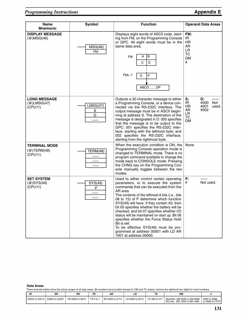
Appendix EProgramming Instructions
131
IR SR HR TR AR LR TC DM #
00000 to 23515 23600 to 25507 HR 0000 to 9915 TR 0 to 7 AR 0000 to 2715 LR 0000 to 6315 TC 000 to 511 Read/Wr: DM 0000 to DM 0999Rd only: DM 1000 to DM 1999
0000 to 9999or 0000 to FFFF
These footnote tables show the actual ranges of all data areas. Bit numbers are provided (except for DM and TC areas); remove the rightmost two digits for word numbers.Data Areas
NameMnemonic
Operand Data AreasFunctionSymbol
DISPLAY MESSAGE(@)MSG(46)
MSG(46)FM
Displays eight words of ASCII code, start-ing from FM, on the Programming Consoleor GPC. All eight words must be in thesame data area.
FM
FM+ 7
C D
A B
D P
ABCD........DP
FM:IRHRARLRTCDM#
LONG MESSAGE(@)LMSG(47)(CPU11) LMSG(47)
SD
–––
Outputs a 32-character message to eithera Programming Console, or a device con-nected via the RS-232C interface. Theoutput message must be in ASCII begin-ning at address S. The destination of themessage is designated in D: 000 specifiesthat the message is to be output to theGPC; 001 specifies the RS-232C inter-face, starting with the leftmost byte; and002 specifies the RS-232C interface,starting from the rightmost byte.
S:IRHRARLRTCDM
D:#000#001#002
–––:Notused.
TERMINAL MODE(@)TERM(48)(CPU11)
TERM(48)–––––––––
When the execution condition is ON, theProgramming Console operation mode ischanged to TERMINAL mode. There is noprogram command available to change themode back to CONSOLE mode. Pressingthe CHNG key on the Programming Con-sole manually toggles between the twomodes.
None
SET SYSTEM(@)SYS(49)(CPU11)
SYS(49)P
––––––
Used to either control certain operatingparameters, or to execute the systemcommands that can be executed from theAR area. The contents of the leftmost 8 bits (i.e., bits08 to 15) of P determine which functionSYS(49) will have. If they contain A3, thenbit 00 specifies whether the battery will bechecked, and bit 07 specifies whether I/Ostatus will be maintained on start up. Bit 06specifies whether the Force Status HoldBit is set. To be effective SYS(49) must be pro-grammed at address 00001 with LD AR1001 at address 00000.
P:#
–––:Not used.

Appendix EProgramming Instructions
132
IR SR HR TR AR LR TC DM #
00000 to 23515 23600 to 25507 HR 0000 to 9915 TR 0 to 7 AR 0000 to 2715 LR 0000 to 6315 TC 000 to 511 Read/Wr: DM 0000 to DM 0999Rd only: DM 1000 to DM 1999
0000 to 9999or 0000 to FFFF
These footnote tables show the actual ranges of all data areas. Bit numbers are provided (except for DM and TC areas); remove the rightmost two digits for word numbers.Data Areas
NameMnemonic
Operand Data AreasFunctionSymbol
BINARY ADD(@)ADB(50)
ADB(50)AuAdR
Adds the 4-digit augend (Au), 4-digit ad-dend (Ad), and content of CY and outputsthe result to the specified result word (R).
Ad
Au
+
+ CY
R
CY
Au/Ad:IRSRHRARLRTCDM#
R:IRHRARLRDM
BINARY SUBTRACT(@)SBB(51) SBB(51)
MiSuR
Subtracts the 4-digit hexadecimal subtra-hend (Su) and content of carry, from the4-digit hexadecimal minuend (Mi), and out-puts the result to the specified result word(R).
Mi
Su
CY
R
CY
–
–
Mi/Su:IRSRHRARLRTCDM#
R:IRHRARLRDM
BINARY MULTIPLY(@)MLB(52)
MLB(52)MdMrR
Multiplies the 4-digit hexadecimal multipli-cand (Md) and 4-digit multiplier (Mr), andoutputs the 8-digit hexadecimal result tothe specified result words (R and R+1). Rand R+1 must be in the same data area.
Md
Mr
R
R+1
X
Quotient
Remainder
Md/Mr:IRSRHRARLRTCDM#
R:IRHRARLRDM
BINARY DIVIDE(@)DVB(53)
DVB(53)DdDrR
Divides the 4-digit hexadecimal dividend(Dd) by the 4-digit divisor (Dr), and outputsresult to the designated result words ( Rand R + 1). R and R + 1 must be in the samedata area.
DdDr
R
R + 1
÷
Quotient
Remainder
Dd/Dr:IRSRHRARLRTCDM#
R:IRHRARLR

Appendix EProgramming Instructions
133
IR SR HR TR AR LR TC DM #
00000 to 23515 23600 to 25507 HR 0000 to 9915 TR 0 to 7 AR 0000 to 2715 LR 0000 to 6315 TC 000 to 511 Read/Wr: DM 0000 to DM 0999Rd only: DM 1000 to DM 1999
0000 to 9999or 0000 to FFFF
These footnote tables show the actual ranges of all data areas. Bit numbers are provided (except for DM and TC areas); remove the rightmost two digits for word numbers.Data Areas
NameMnemonic
Operand Data AreasFunctionSymbol
DOUBLE BCD ADD(@)ADDL(54)
ADDL(54)AuAdR
Adds two 8-digit values (2 words each) andthe content of CY, and outputs the result tothe specified result words. All words forany one operand must be in the same dataarea.
Au + 1
+ Ad + 1
+
CY R + 1
CY
Au
Ad
R
Au/Ad:IRSRHRARLRTCDM
R:IRHRARLRDM
DOUBLE BCD SUBTRACT(@)SUBL(55)
SUBL(55)MiSuR
Subtracts both the 8-digit BCD subtrahendand the content of CY from an 8-digit BCDminuend, and outputs the result to the spe-cified result words. All words for any oneoperand must be in the same data area.
Mi + 1 Mi
– Su + 1 Su
–
CY R + 1 R
CY
Mi/Su:IRSRHRARLRTCDM
R:IRHRARLRDM
DOUBLE BCD MULTIPLY(@)MULL(56) MULL(56)
MdMrR
Multiplies the 8-digit BCD multiplicand and8-digit BCD multiplier, and outputs the re-sult to the specified result words. All wordsfor any one operand must be in the samedata area.
Md + 1 Md
Mr + 1 Md
R + 3 R + 2 R + 1 R
X
Md/Mr:IRSRHRARLRTCDM
R:IRHRARLRDM

Appendix EProgramming Instructions
134
IR SR HR TR AR LR TC DM #
00000 to 23515 23600 to 25507 HR 0000 to 9915 TR 0 to 7 AR 0000 to 2715 LR 0000 to 6315 TC 000 to 511 Read/Wr: DM 0000 to DM 0999Rd only: DM 1000 to DM 1999
0000 to 9999or 0000 to FFFF
These footnote tables show the actual ranges of all data areas. Bit numbers are provided (except for DM and TC areas); remove the rightmost two digits for word numbers.Data Areas
NameMnemonic
Operand Data AreasFunctionSymbol
DOUBLE BCD DIVIDE(@)DIVL(57) DIVL(57)
DdDrR
Divides the 8-digit BCD dividend by an8-digit BCD divisor, and outputs the resultto the specified result words. All words forany one operand must be in the same dataarea.
Dd + 1 Dd
Dr + 1 Dr
R + 1 R
R + 3 R + 2
Quotient
Remainder
÷
Dd/Dr:IRSRHRARLRTCDM
R:IRHRARLRDM
DOUBLEBCD-TO-DOUBLEBINARY (@)BINL(58) BINL(58)
SR
Converts the BCD value of the two sourcewords (S: starting word) into binary andoutputs the converted data to the two resultwords (R: starting word). All words for anyone operand must be in the same dataarea.
S
S + 1
R
R + 1
S:IRSRHRARLRTCDM
R:IRHRARLRDM
DOUBLEBINARY-TO-DOUBLEBCD(@)BCDL(59)
BCDL(59)SR
Converts the binary value of the twosource words (S: starting word) into eightdigits of BCD data, and outputs the con-verted data to the two result words (R:starting result word). Both words for anyone operand must be in the same dataarea.
S
S + 1
R
R + 1
S:IRSRHRARLRDM
R:IRHRARLRDM
DOUBLE COMPARECMPL(60)(CPU11) CMPL(60)
S1S2
Compares the 8-digit hexadecimal valuesin words S1+1 and S1 with the values inS2+1 and S2, and indicates the result usingthe Greater Than, Less Than, and EqualFlags in the AR area. S1+1 and S2+1 areregarded as the most significant data ineach pair of words.
S1,S2:IRSRHRARLRTCDM

Appendix EProgramming Instructions
135
IR SR HR TR AR LR TC DM #
00000 to 23515 23600 to 25507 HR 0000 to 9915 TR 0 to 7 AR 0000 to 2715 LR 0000 to 6315 TC 000 to 511 Read/Wr: DM 0000 to DM 0999Rd only: DM 1000 to DM 1999
0000 to 9999or 0000 to FFFF
These footnote tables show the actual ranges of all data areas. Bit numbers are provided (except for DM and TC areas); remove the rightmost two digits for word numbers.Data Areas
NameMnemonic
Operand Data AreasFunctionSymbol
COLUMN-TO-WORD(@)CTW(63)(CPU11) CTW(63)
SCD
Fetches data from the same numbered bit(C) in 16 consecutive words (where S is theaddress of the first source word), andcreates a 4-digit word by consecutivelyplacing the data in the bits of the destina-tion word, D. The bit from word S is placed into bit 00 ofD, the bit from word S+1 is placed into bit01, etc.
S
S+1
S+15
0
1
0
0
1
0
00
01
15
Bit C D
S:IRSRHRARLRTCDM
C:IRSRHRARLRTCDM#
D:IRSRHRARLRTCDM
WORD-TO-COLUMN(@)WTC(64)(CPU11) WTC(64)
SDC
Places bit data from the source word (S),consecutively into the same numberedbits of the 16 consecutive destinationwords (where D is the address of the firstdestination word). Bit 00 from word S is placed into bit C ofword D, bit 01 from word S is placed intobit C of word D+1, etc.
D
D+1
D+15
1
1
0
1
1
0
00
01
15
Bit CS
S:IRSRHRARLRTCDM
D:IRSRHRARLRTCDM
C:IRSRHRARLRTCDM#
HOURS-TO-SECONDS(@)HTS(65)(CPU11)
HTS(65)SR
–––
Converts a time given in hours/minutes/seconds (S and S+1) to an equivalent timein seconds only (R and R+1). S and S+1must be BCD and within one data area. Rand R+1 must also be within one dataarea.
S:IRSRHRARLRTCDM
R:IRSRHRARLRTCDM
–––:Notused.
SECONDS-TO-HOURS(@)STH(66)(CPU11)
STH(66)SR
–––
Converts a time given in seconds (S andS+1) to an equivalent time in hours/minu-tes/seconds (R and R+1). S and S+1 mustbe BCD between 0 and 35,999,999, andwithin the same data area. R and R+1must also be within one data area.
S:IRSRHRARLRTCDM
R:IRSRHRARLRTCDM
–––:Notused.

Appendix EProgramming Instructions
136
IR SR HR TR AR LR TC DM #
00000 to 23515 23600 to 25507 HR 0000 to 9915 TR 0 to 7 AR 0000 to 2715 LR 0000 to 6315 TC 000 to 511 Read/Wr: DM 0000 to DM 0999Rd only: DM 1000 to DM 1999
0000 to 9999or 0000 to FFFF
These footnote tables show the actual ranges of all data areas. Bit numbers are provided (except for DM and TC areas); remove the rightmost two digits for word numbers.Data Areas
NameMnemonic
Operand Data AreasFunctionSymbol
BIT COUNTER(@)BCNT(67) BCNT(67)
NSBR
Counts the number of ON bits in one ormore words (SB is the beginning sourceword) and outputs the result to the speci-fied result word (R). N gives the number ofwords to be counted. All words in which bitare to be counted must be in the same dataarea.
N:IRSRHRARLRTCDM
R:IRHRARLRTCDM
SB:IRSRHRARLRTCDM
BLOCK COMPARE(@)BCMP(68)
BCMP(68)S
CBR
Compares a 1-word binary value (S) withthe 16 ranges given in the comparisontable (CB is the starting word of the com-parison block). If the value falls within anyof the ranges, the corresponding bits in theresult word (R) will be set. The comparisonblock must be within one data area.
S
CB CB+1CB+2 CB+3CB+4 CB+5
CB+30 CB+31
101
0
Lower limit Upper limit
Lower limit ≤ S ≤ Upper limit 1
Result
S:IRSRHRARLRTCDM#
CB:IRSRHRLRTCDM
R:IRHRARLRTCDM
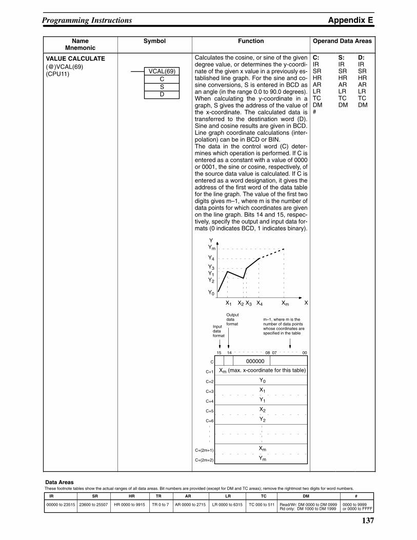
Appendix EProgramming Instructions
137
IR SR HR TR AR LR TC DM #
00000 to 23515 23600 to 25507 HR 0000 to 9915 TR 0 to 7 AR 0000 to 2715 LR 0000 to 6315 TC 000 to 511 Read/Wr: DM 0000 to DM 0999Rd only: DM 1000 to DM 1999
0000 to 9999or 0000 to FFFF
These footnote tables show the actual ranges of all data areas. Bit numbers are provided (except for DM and TC areas); remove the rightmost two digits for word numbers.Data Areas
NameMnemonic
Operand Data AreasFunctionSymbol
VALUE CALCULATE(@)VCAL(69)(CPU11) VCAL(69)
CSD
Xm (max. x-coordinate for this table)
Y0
X1
Y1
X2
Y2
Xm
Ym
Calculates the cosine, or sine of the givendegree value, or determines the y-coordi-nate of the given x value in a previously es-tablished line graph. For the sine and co-sine conversions, S is entered in BCD asan angle (in the range 0.0 to 90.0 degrees).When calculating the y-coordinate in agraph, S gives the address of the value ofthe x-coordinate. The calculated data istransferred to the destination word (D).Sine and cosine results are given in BCD.Line graph coordinate calculations (inter-polation) can be in BCD or BIN.The data in the control word (C) deter-mines which operation is performed. If C isentered as a constant with a value of 0000or 0001, the sine or cosine, respectively, ofthe source data value is calculated. If C isentered as a word designation, it gives theaddress of the first word of the data tablefor the line graph. The value of the first twodigits gives m–1, where m is the number ofdata points for which coordinates are givenon the line graph. Bits 14 and 15, respec-tively, specify the output and input data for-mats (0 indicates BCD, 1 indicates binary).
Y
XXmX4X3X2X1
Ym
Y4
Y3Y1Y2
Y0
15 14 08 07 00
000000
Inputdataformat
Outputdataformat
m–1, where m is thenumber of data pointswhose coordinates arespecified in the table
C
C+1
C+2
C+3
C+4
C+5
C+6
C+(2m+1)
C+(2m+2)
C:IRSRHRARLRTCDM#
S:IRSRHRARLRTCDM
D:IRSRHRARLRTCDM

Appendix EProgramming Instructions
138
IR SR HR TR AR LR TC DM #
00000 to 23515 23600 to 25507 HR 0000 to 9915 TR 0 to 7 AR 0000 to 2715 LR 0000 to 6315 TC 000 to 511 Read/Wr: DM 0000 to DM 0999Rd only: DM 1000 to DM 1999
0000 to 9999or 0000 to FFFF
These footnote tables show the actual ranges of all data areas. Bit numbers are provided (except for DM and TC areas); remove the rightmost two digits for word numbers.Data Areas
NameMnemonic
Operand Data AreasFunctionSymbol
BLOCK TRANSFER(@)XFER(70)
XFER(70)NSD
Moves the content of several consecutivesource words (S gives the address of thestarting source word) to consecutive desti-nation words (D is the starting destinationword). All source words must be in thesame data area, as must all destinationwords. Transfers can be within one dataarea or between two data areas, but thesource and destination words must notoverlap.
S
S + 1
D
D + 1
S+N–1 D+N–1
No. ofWords
N:IRSRHRARLRTCDM#
S :IRHRARLRTCDM
D:IRSRHRARLRTCDM#
BLOCK SET(@)BSET(71)
BSET(71)SStE
Copies the content of one word or constant(S) to several consecutive words (from thestarting word, St, through to the endingword, E). St and E must be in the samedata area.
S St
E
St/E:IRHRARLRTCDM
S:IRSRHRARLRTCDM#
SQUARE ROOT(@)ROOT(72)
ROOT(72)SqR
Computes the square root of an 8-digitBCD value (Sq and Sq + 1) and outputs thetruncated 4-digit, integer result to the spe-cified result word (R). Sq and Sq + 1 mustbe in the same data area.
Sq+1 Sq
R
Sq:IRSRHRARLRTCDM
R:IRHRARLRDM
DATA EXCHANGE(@)XCHG(73)
XCHG(73)E1E2
Exchanges the contents of two words (E1and E2).
E1 E2
E1/E2:IRHRARLRTCDM

Appendix EProgramming Instructions
139
IR SR HR TR AR LR TC DM #
00000 to 23515 23600 to 25507 HR 0000 to 9915 TR 0 to 7 AR 0000 to 2715 LR 0000 to 6315 TC 000 to 511 Read/Wr: DM 0000 to DM 0999Rd only: DM 1000 to DM 1999
0000 to 9999or 0000 to FFFF
These footnote tables show the actual ranges of all data areas. Bit numbers are provided (except for DM and TC areas); remove the rightmost two digits for word numbers.Data Areas
NameMnemonic
Operand Data AreasFunctionSymbol
ONE DIGIT SHIFT LEFT(@)SLD(74)
SLD(74)StE
Shifts all data, between the starting word(St) and ending word (E), one digit (fourbits) to the left, writing zero into the right-most digit of the starting word. St and Emust be in the same data area.
E
St
St + 1
0
St/E:IRHRARLRDM
ONE DIGIT SHIFTRIGHT(@)SRD(75)
SRD(75)ESt
0 St
Shifts all data, between starting word (St)and ending word (E), one digit (four bits) tothe right, writing zero into the leftmost digitof the ending word. St and E must be in thesame data area.
E
E – 1
St/E:IRHRARLRDM
4-TO-16 DECODER(@)MLPX(76)
MLPX(76)SDiR
Converts up to four hexadecimal digits inthe source word (S), into decimal valuesfrom 0 to 15, and turns ON the correspond-ing bit(s) in the result word(s) (R). There isone result word for each converted digit.Digits to be converted are designated byDi. (The rightmost digit specifies the firstdigit. The next digit to the left gives thenumber of digits to be converted minus 1.The two leftmost digits are not used.)
S 0 to F
R
0015
S:IRSRHRARLRTCDM
Di:IRHRARLRTCDM#
R:IRHRARLRDM
16-TO-4 ENCODER(@)DMPX(77)
DMPX(77)SRDi
Determines the position of the leftmost ONbit in the source word(s) (starting word: S)and turns ON the corresponding bit(s) inthe specified digit of the result word (R).One digit is used for each source word.Digits to receive the converted values aredesignated by Di. (The rightmost digitspecifies the first digit. The next digit to leftgives the number of words to be convertedminus 1. The two leftmost digits are notused.)
S
15 00
0 to FR
S:IRSRHRARLRTCDM
R:IRHRARLRDM
Di:IRHRARLRTCDM#

Appendix EProgramming Instructions
140
IR SR HR TR AR LR TC DM #
00000 to 23515 23600 to 25507 HR 0000 to 9915 TR 0 to 7 AR 0000 to 2715 LR 0000 to 6315 TC 000 to 511 Read/Wr: DM 0000 to DM 0999Rd only: DM 1000 to DM 1999
0000 to 9999or 0000 to FFFF
These footnote tables show the actual ranges of all data areas. Bit numbers are provided (except for DM and TC areas); remove the rightmost two digits for word numbers.Data Areas
NameMnemonic
Symbol Function Operand Data Areas
7-SEGMENT DECODER(@)SDEC(78)
SDEC(78)SDiD
Converts hexadecimal values from thesource word (S) into 7-segment displaydata. Results are placed in consecutivehalf-words, starting at the first destinationword (D). Di gives digit and destination de-tails. (The rightmost digit gives the first digitto be converted. The next digit to the leftgives the number of digits to be convertedminus 1. If the next digit is 1, the first con-verted data is transferred to left half of thefirst destination word. If it is 0, the transferis to the right half).
S
D 0 to F
S:IRSRHRARLRTCDM
Di:IRHRARLRTCDM#
D:IRHRARLRDM
FLOATING POINT DIVIDE(@)FDIV(79) FDIV(79)
DdDrR
Divides one floating point value by anotherand outputs a floating point result. Therightmost seven digits of each set of twowords (eight digits) are used for mantissa,and the leftmost digit is used for the expo-nent and its sign (Bits 12 to 14 give the ex-ponent value, 0 to 7. If bit 15 is 0, the expo-nent is positive; if it’s 1, the exponent isnegative).
÷
Dd + 1 Dd
Dr + 1 Dr
R + 1 R
Dd/Dr:IRSRHRARLRTCDM
R:IRHRARLRDM
SINGLE WORD DISTRIBUTE(@)DIST(80) DIST(80)
SDBsOf
Moves one word of source data (S) to thedestination word whose address is givenby the destination base word (DBs) plusoffset (Of).
S Base (DBs)+
Offset (OF)
(S) (DBs + Of)
S:IRSRHRARLRTCDM#
DBs:IRHRARLRTCDM
Of:IRHRARLRTCDM#

Appendix EProgramming Instructions
141
IR SR HR TR AR LR TC DM #
00000 to 23515 23600 to 25507 HR 0000 to 9915 TR 0 to 7 AR 0000 to 2715 LR 0000 to 6315 TC 000 to 511 Read/Wr: DM 0000 to DM 0999Rd only: DM 1000 to DM 1999
0000 to 9999or 0000 to FFFF
These footnote tables show the actual ranges of all data areas. Bit numbers are provided (except for DM and TC areas); remove the rightmost two digits for word numbers.Data Areas
NameMnemonic
Operand Data AreasFunctionSymbol
DATA COLLECT(@)COLL(81)
COLL(81)SBsOfD
Extracts data from the source word andwrites it to the destination word (D). Thesource word is determined by adding theoffset (Of) to the address of the sourcebase word (SBs).
Base (DBs)+
Offset (OF)
(SBs+Of) (D)
SBs:IRSRHRARLRTCDM
Of:IRHRARLRTCDM#
D:IRHRARLRTCDM
MOVE BIT(@)MOVB(82)
MOVB(82)SBiD
Transfers the designated bit of the sourceword or constant (S) to the designated bitof the destination word (D). The rightmosttwo digits of the bit designator (Bi) specifythe source bit. The two leftmost digitsspecify the destination bit.
S
D
S:IRSRHRARLRDM#
Bi:IRHRARLRTCDM#
D:IRHRARLRDM
MOVE DIGIT(@)MOVD(83)
MOVD(83)SDiD
Moves hexadecimal content of up to fourspecified 4-bit source digit(s) from thesource word to the specified destinationdigit(s) (S gives the source word address.D specifies the destination word). Specificdigits within the source and destinationwords are defined by the Digit Designator(Di) digits. (The rightmost digit gives thefirst source digit. The next digit to the leftgives the number of digits to be moved.The next digit specifies the first digit in thedestination word.)
S
D
15 00
S:IRSRHRARLRTCDM#
Di:IRHRARLRTCDM#
D:IRSRHRARLRTCDM

Appendix EProgramming Instructions
142
IR SR HR TR AR LR TC DM #
00000 to 23515 23600 to 25507 HR 0000 to 9915 TR 0 to 7 AR 0000 to 2715 LR 0000 to 6315 TC 000 to 511 Read/Wr: DM 0000 to DM 0999Rd only: DM 1000 to DM 1999
0000 to 9999or 0000 to FFFF
These footnote tables show the actual ranges of all data areas. Bit numbers are provided (except for DM and TC areas); remove the rightmost two digits for word numbers.Data Areas
NameMnemonic
Operand Data AreasFunctionSymbol
REVERSIBLE SHIFTREGISTER(@)SFTR(84) SFTR(84)
CStE
Shifts bits in the specified word or series ofwords either left or right. Starting (St) andending words (E) must be specified. Con-trol word (C) contains shift direction, resetinput, and data input. (Bit 12: 0 = shift right,1 = shift left. Bit 13 is the value shifted intothe source data, with the bit at the oppositeend being moved to CY. Bit 14: 1 = shift en-abled, 0 = shift disabled. If bit 15 is ONwhen SFTR(89) is executed with an ONcondition, the entire shift register and CYwill be set to zero.) St and E must be in thesame data area and St must be less thanor equal to E.
CY
E St
15
00
CY
E
IN
St IN
001112131415
Not usedC
00 15 00
15 00 15
St/E/C:IRHRARTCLRDM
TABLE COMPARE(@)TCMP(85)
TCMP(85)CDTBR
Compares a 4-digit hexadecimal value(CD) with values in table consisting of 16words (TB: is the first word of the compari-son table). If the value of CD falls withinany of the comparison ranges, corre-sponding bits in result word (R) are set (1for agreement, and 0 for disagreement).The table must be entirely within the onedata area.
CD Tb
Tb + 1
Tb + 13Tb + 14
Tb + 15
1: agreement0: disagreement
0
1
10
1
R
0
CD:IRSRHRARLRTCDM#
TB/R:IRHRARLRTCDM

Appendix EProgramming Instructions
143
IR SR HR TR AR LR TC DM #
00000 to 23515 23600 to 25507 HR 0000 to 9915 TR 0 to 7 AR 0000 to 2715 LR 0000 to 6315 TC 000 to 511 Read/Wr: DM 0000 to DM 0999Rd only: DM 1000 to DM 1999
0000 to 9999or 0000 to FFFF
These footnote tables show the actual ranges of all data areas. Bit numbers are provided (except for DM and TC areas); remove the rightmost two digits for word numbers.Data Areas
NameMnemonic
Operand Data AreasFunctionSymbol
ASCII CONVERT(@)ASC(86)
ASC(86)SDiD
Converts hexadecimal digits from thesource word (S) into 8-bit ASCII values,starting at leftmost or rightmost half of thestarting destination word (D). The right-most digit of Di designates the first sourcedigit. The next digit to the left gives thenumber of digits to be converted. The nextdigit specifies the whether the data is to betransferred to the rightmost (0) or leftmost(1) half of the first destination word. Theleftmost digit specifies parity:
0: none,1: even, or2: odd.
S
D 8-bitdata
0 to F
15 08 07 00
S:IRSRHRARLRTCDM
Di:IRHRLRTCDM#
D:IRHRLRDM
INTERRUPT CONTROL(@)INT(89)
INT(89)CCND
Controls programmed (scheduled) inter-rupts and interrupts from Interrupt InputUnits. Each PC can have up to 4 IIUs. N de-fines the source of the interrupt: 000 to 003designate the no. of the IIU; 004 desig-nates a scheduled interrupt. In IIUs, bits 00to 07 identify the interrupting subroutine,higher bits are not used. Bit 00 of Unit 0 cor-responds to interrupt subroutine 00,through to bit 07 of Unit 3 which corre-sponds to subroutine 31. CC is the controlcode, the meaning of which depends onthe value of N, as follows:
CC N = 000 to 003 N = 004
000
001
002
Masks and unmasks in-terrupt bits for the desig-nated Unit (N) accordingto the data in D. Bits cor-responding to ON bits inD are masked, those cor-responding to OFF bitsare unmasked. Maskedbits are recorded and willbe executed when theyare unmasked (unlesspreviously cleared).
Clears the masked inter-rupt bits of the designatedUnit (N) according to thecorresponding ON bits inD. The subroutines corre-sponding to bits clearedin this manner will not beexecuted when the bit isunmasked.
Copies the mask status ofthe designated IIU to D.
The interrupt timeinterval is set ac-cording to the datain D (00.01 to99.99 s) The deci-mal point is notentered. The in-terrupt is can-celled if D is00.00.
The time to thefirst interrupt is setaccording to thedata in D (00.01 to99.99 s) The deci-mal point is notentered. The in-terrupt is can-celled if D is00.00.
Copies the time in-terval data to D.
CC:000 to002
N:000 to004
D:IRHRARLRTCDM#

Appendix EProgramming Instructions
144
IR SR HR TR AR LR TC DM #
00000 to 23515 23600 to 25507 HR 0000 to 9915 TR 0 to 7 AR 0000 to 2715 LR 0000 to 6315 TC 000 to 511 Read/Wr: DM 0000 to DM 0999Rd only: DM 1000 to DM 1999
0000 to 9999or 0000 to FFFF
These footnote tables show the actual ranges of all data areas. Bit numbers are provided (except for DM and TC areas); remove the rightmost two digits for word numbers.Data Areas
NameMnemonic
Operand Data AreasFunctionSymbol
NETWORK SEND(@)SEND(90)(CPU11) SEND(90)
SDC
Transfers data from n source words (S isthe starting word) to the destination words(D is the first address) in node N of the spe-cified network (in a SYSMAC LINK or NETLink System). The format of the controlwords varies depending on the type of sys-tem. In both types of systems, the first con-trol word (C) gives the number of words tobe transferred. For NET Link Systems, in word C+1, bit 14specifies the system (0 for system 1, and1 for system 0), and the rightmost 7 bits de-fine the network number. The left half ofword C+2 specifies the destination port(00: NSB, 01/02: NSU), and the right halfspecifies the destination node number. Ifthe destination node number is set to 0,data is transmitted to all nodes. For SYSMAC LINK Systems, the right halfof C+1 specifies the response monitoringtime (default 00: 2 s, FF: monitoring dis-abled), the next digit to the left gives themaximum number of re-transmissions (0to 15) that the PC will attempt if no re-sponse signal is received. Bit 13 specifieswhether a response is needed (0) or not(1), and bit 14 specifies the system number(0 for system 1, and 1 for system 0). Theright half of C+2 gives the destination nodenumber. If this is set to 0, the data will besent to all nodes.
C
C+1
C+2
C
C+1
NET Link
SYSMAC LINK
n: no. of words to be transmitted (0 to 1000)
0X00 0000 Network no. (0 to 127)
Destination port no. Destination node no.(0 to 126)
n: no. of words to be transmitted, 0 to 1000
0XX0 Re-trans-missions
Response monitor time(0.1 to 25.4 s)
0000 Destination node no.(0 to 62)
0000C+2
Destination node NSource N
S
S+1
S+n–1
D
D+1
D+n–1
S:IRSRHRARLRTCDM
D/C:IRHRARLRTCDM
SUBROUTINE ENTER(@)SBS(91)
SBS(91) N
Calls subroutine N. Moves program opera-tion to the specified subroutine.
N:00 to 99

Appendix EProgramming Instructions
145
IR SR HR TR AR LR TC DM #
00000 to 23515 23600 to 25507 HR 0000 to 9915 TR 0 to 7 AR 0000 to 2715 LR 0000 to 6315 TC 000 to 511 Read/Wr: DM 0000 to DM 0999Rd only: DM 1000 to DM 1999
0000 to 9999or 0000 to FFFF
These footnote tables show the actual ranges of all data areas. Bit numbers are provided (except for DM and TC areas); remove the rightmost two digits for word numbers.Data Areas
NameMnemonic
Operand Data AreasFunctionSymbol
SUBROUTINE STARTSBN(92)
SBN(92) N
Marks the start of subroutine N. N:00 to 99
RETURNRET(93) RET(93)
Marks the end of a subroutine and returnscontrol to the main program.
None
WATCHDOG TIMER REFRESH(@)WDT(94) WDT(94) T
Sets the maximum and minimum limits forthe watchdog timer (normally 0 to 130 ms).New limits:Maximum time = 130 + (100 x T)Minimum time = 130 + (100 x (T–1))
T:0 to 63
I/O REFRESH(@)IORF(97)
IORF(97)StE
Refreshes all I/O words between the start(St) and end (E) words. Only I/O wordsmay be designated. Normally these wordsare refreshed only once per cycle, but re-freshing words before use in an instructioncan increase execution speed. St must beless than or equal to E.
St/E:IR

Appendix EProgramming Instructions
146
IR SR HR TR AR LR TC DM #
00000 to 23515 23600 to 25507 HR 0000 to 9915 TR 0 to 7 AR 0000 to 2715 LR 0000 to 6315 TC 000 to 511 Read/Wr: DM 0000 to DM 0999Rd only: DM 1000 to DM 1999
0000 to 9999or 0000 to FFFF
These footnote tables show the actual ranges of all data areas. Bit numbers are provided (except for DM and TC areas); remove the rightmost two digits for word numbers.Data Areas
NameMnemonic
Operand Data AreasFunctionSymbol
NETWORK RECEIVE(@)RECV(98)(CPU11) RECV(98)
SDC
n: no. of words to be transmitted, 0 to 1000
Response monitor time(0.1 to 25.4 s)
Source node no.(0 to 62)
n: no. of words to be transmitted (0 to 1000)
Network no. (0 to 127)
Source node no.(0 to 126)
Transfers data from the source words (S isthe first word) from node N of the specifiednetwork (in a SYSMAC LINK or NET LinkSystem) to the destination words startingat D. The format of the control words va-ries depending on the type of system. Inboth types of systems, the first controlword (C) gives the number of words to betransferred.For NET Link Systems, in the second word(C+1), bit 14 specifies the system (0 forsystem 1, and 1 for system 0), and therightmost 7 bits define the network num-ber. The left half of word C+2 specifies thesource port (00: NSB, 01/02: NSU), andthe right half specifies the source nodenumber.For SYSMAC LINK Systems, the right halfof C+1 specifies the response monitoringtime (default 00: 2 s, FF: monitoring dis-abled), the next digit to the left gives themaximum number of re-transmissions (0to 15) that the PC will attempt if no re-sponse signal is received. Bit 13 specifieswhether a response is needed (0) or not(1), and bit 14 specifies the system num-ber (0 for system 1, and 1 for system 0).The right half of C+2 gives the sourcenode number.
C
C+1
C+2
C
C+1
NET Link
SYSMAC LINK
0X00 0000
Source port no.(NSB: 00, NSU: 01/02)
0XX0 Re-trans-missions
0000 0000C+2
Destination nodeSource node N
S
S+1
S+n–1
D
D+1
D+n–1
S:IRSRHRARLRTCDM
C/D:IRHRARLRTCDM

147
Glossary
ASCII code [A(merican) S(tandard) C(ode for) I(nformation) I(nterchange)] A standardcomputer code used to facilitate the interchange of information among vari-ous types of data-processing equipment.
ASCII Unit An Intelligent I/O Unit. The ASCII Unit has its own CPU and 16 kilobytes ofmemory. This Unit enables communication between the PC and any otherdevice which uses ASCII code. The ASCII Unit can be programmed in BA-SIC.
Backplane A base to which Units are mounted to form a Rack. Backplanes provide aseries of connectors for these Units along with wiring to connect them to theCPU and Power Supply. Backplanes also provide connectors used to con-nect them to other Backplanes. In some Systems, different Backplanes areused for different Racks; in other Systems, Racks differ only by the Unitsmounted to them.
back-up A copy of existing data which is valuable if data is accidentally erased.
baud rate Transfer speed between two devices in a system measured in bits persecond. For example, an optical sensor might be configured to send its infor-mation to the FIT at 9600 baud. It is important for both of the devices to beset to the same baud rate.
bit The smallest piece of information that can be represented on a computer. Abit has the value of either zero or one, corresponding to the electrical signalsON and OFF. A bit is one binary digit.
central processing unit A device that is capable of storing a program and data, and executing the setof instructions contained in the program. In a PC System, the central pro-cessing unit executes the program, processes I/O signals, communicateswith external devices, etc.
communication cable Cable used to transfer data between components of a control system andconforming to the RS-232C or RS-422 standards.
Control System All of the hardware and software components used to control other devices.A Control System includes the PC System, the PC programs, and all I/O de-vices that are used to control or obtain feedback from the controlled system.
counter A PC function that counts the number of occurrences of a certain event.
CPU An acronym for central processing unit.
cycle time The total time it takes the PC to perform internal operations, i.e., reset thewatchdog timer, read the program, receive input data, send output data, andexecute instructions. Cycle time is monitored by the watchdog timer withinthe PC, and if it takes longer than a certain specified amount of time, an errormessage may be generated, or the CPU may just stop. Cycle times will differdepending on the configuration of the system.
data area An area in the PC’s memory that is designed to hold a specific type of data,e.g., the LR area is designed to hold common data in a PC Link System.

Glossary
148
data disk Floppy disk used to store information such as programs or I/O tables. Thedata disk should be used in drive B of the FIT.
data link Allows for the connection of up to 32 PCs in a Net Link System where each iscontributing information to a common memory area. Data links may be estab-lished in the LR and/or DM memory areas.
debugging The process of checking for errors in a program.
default condition The original condition of a function or system. For example, the FIT’s defaultcondition is to start from its hard drive, but this default condition can bechanged so that it starts from a floppy disk drive.
distributed control An automation concept in which control of each portion of an automated sys-tem is located near the devices actually being controlled, i.e., control is de-centralized and “distributed” over the system. Distributed control is a conceptbasic to PC Systems.
EEPROM [E(lectrically) E(rasable) P(rogrammable) R(ead) O(nly) M(emory)] A type ofROM in which stored data can be erased and reprogrammed. This is accom-plished using a special control lead connected to the EEPROM chip and canbe done without having to remove the EEPROM chip from the device inwhich it is mounted.
electrical noise Electric ‘static’ that can disturb electronic communications. The ‘snow’ thatcan appear on a TV screen is an example of the effects of electrical noise.
EPROM [E(rasable) P(rogrammable) R(ead) O(nly) M(emory)] A type of ROM inwhich stored data can be erased, by ultraviolet light or other means, and re-programmed.
Expansion I/O Unit An I/O Unit for a Package-type PC that provides more I/O points to the PC.
factory computer A general-purpose computer, usually quite similar to a business computer,that is used in automated factory control.
flag A bit that is turned ON and OFF automatically by the system in order to pro-vide status information.
High-speed Counter A Special I/O Unit. A High Speed Counter Unit counts independently of thePC’s cycle time. This allows counting of very short, fast signals.
host computer A computer that is used to transfer data to or receive data from a PC in aHost Link system. The host computer is used for data management andoverall system control. Host computers are generally small personal or busi-ness computers.
IBM PC/XT or AT,
or compatibles A computer that has similar architecture to, and is logically compatible withan IBM PC/XT computer; and that can run software designed for that com-puter.
instruction line A succession of instructions which begins with a load instruction at the leftbus bar and ends at a right bus bar.
Glossary
149
interface An interface is the conceptual boundary between systems or devices andusually involves changes in the way the communicated data is represented.Interface devices such as NSBs perform operations such as changing thecoding, format, or speed of data.
I/O devices The devices which are connected to the terminals on I/O Units, Special I/OUnits, or Intelligent I/O Units. I/O devices may be part of the Control System ifthey function to help control other devices, or they may be part of the con-trolled system if they interact directly with it.
I/O point The place at which an input signal enters the PC System or an output signalleaves the PC System. In physical terms, an I/O point corresponds to termi-nals or connector pins on a Unit; in terms of programming, an I/O point corre-sponds to an I/O bit in the IR area.
I/O table Diagram written to the IR memory area listing the type of I/O units controlledby a PC. It must be cleared before programming or when I/O units arechanged. Tables can be read, verified, or transferred to a EPROM.
I/O Unit The most basic type of Unit mounted to a Backplane. I/O Units include InputUnits and Output Units, each of which is available in a range of specifica-tions. I/O Units do not include Special I/O Units, Link Units, etc.
Limit Switch A switch that detects when an object has reached the limit of its movementby actually making contact with the object. Limit Switches are fitted to electricelevators, traveling cranes, etc. to indicate when a certain part of the equip-ment has traveled to the specified limit.
Link Unit Any of the Units used to connect a PC to a Link System. These are RemoteI/O Units, I/O Link Units, PC Link Units, Host Link Units, and Net Link Units.
operating mode The Display Terminal Unit can operate in five different modes: Page Read,Terminal, Dynamic Scan, Read/Write, and Self-Diagnosis.
page One complete Display Terminal Unit screen. Two hundred screens can bestored on one RAM card.
parallel interface The parallel interface uses the RS-232 connector, but is not serial communi-cation. When parallel mode is selected as the communication mode, up to 16Display Terminal Units can be connected to a PC in parallel.
PC An acronym for Programmable Controller.
PCB An acronym for printed circuit board.
PC Link Unit A Unit used to connect two or more PCs together so that they can exchangedata through their LR areas.
Photoelectric Switch A switch that uses light to detect the presence of an object.
Power Supply A Unit that mounts to a Backplane in a Rack PC. It provides power at thevoltage required by the other Units on the Rack.
printed circuit board A board onto which electrical circuits are printed for mounting into a comput-er or electrical device.

Glossary
150
Programmable Controller A small, computer-like device that can control peripheral equipment, such asan electric door or quality control devices, based on programming and pe-ripheral input devices. Any process that can be controlled using electricalsignals can be controlled by a PC. PCs can be used independently or net-worked together into a system to control more complex operations.
programming device A peripheral device used to write programs and to input a program to a PC orto alter or monitor a program already stored in the PC. There are dedicatedprogramming devices, such as Programming Consoles, and there are non-dedicated programming devices, such as a host computer.
PROM [P(rogrammable) R(ead) O(nly) M(emory)] A type of ROM into which the pro-gram or data may be written after manufacture, by a customer, but which isfixed from that time on.
PROM Writer A PROM Writer is a device used to write data to ROM, PROM, and EPROMstorage chips.
Proximity Switch A switch that uses magnetic induction to measure the distance of a metallicobject from the front of the switch.
Rack PC A PC that is composed of Units mounted to one or more Racks. This configu-ration is the most flexible, and most large PCs are Rack PCs. A Rack PC isthe opposite of a Package-type PC, which has all of the basic I/O, storage,and control functions built into a single package.
RAM [R(andom) A(ccess) M(emory)] RAM will not retain data when power is dis-connected. Therefore data should not be stored in RAM.
register/registered Storing text and graphics in the RAM/ROM card from a personal computer orthe ASCII Unit. Graphics that have been written to the RAM/ROM card arereferred to as registered messages.
Remote I/O Unit A Unit that extends the distance an Expansion I/O Unit can be from the CPU.
ROM [R(ead) O(nly) M(emory)] A type of digital storage that cannot be written to. AROM chip is manufactured with its program or data already stored in it, and itcan never be changed. However, the program or data can be read as manytimes as desired.
switching capacity The voltage/current that relay can switch ON and OFF.
stepping motor An output device that rotates according to signals from the Control System.The rotation is very precise and occurs in pre-defined “steps”.
switch An input device that sends either an ON or OFF signal to the Control System.A switch can be operated either by a person or by the movement of a pieceof equipment or material.
system configuration The arrangement in which Units in a System are connected. This term refersto the conceptual arrangement and wiring together of all the devices neededto comprise the System. In OMRON terminology, system configuration isused to describe the arrangement and connection of the Units comprising aControl System that includes one or more PCs.

Glossary
151
Unit In OMRON PC terminology, the word Unit is capitalized to indicate any prod-uct sold for a PC System. though most of the names of these products endwith the word Unit, not all do, e.g., a Remote Terminal is referred to in a col-lective sense as a Unit. Context generally makes any limitations of this wordclear.
watchdog timer A special timer inside the CPU that monitors the PC’s cycle time. The watch-dog timer sets a flag if the cycle time becomes longer than a certain specifiedvalue. This is useful if the correct operation of your System depends on acertain maximum cycle time.
word In digital circuits, a group of bits. Usually a word consists of four, eight, orsixteen bits. In C-series PCs, a word consists of sixteen bits. Words can beused to store data, or they can be used for I/O.
work bits Bits in the IR area that are not being used for input or output. These bits canbe used in the program in any way desired.


153
Index
���
Assemblybackplane, , connecting cable, CPU,Expansion I/O Unit, I/O Units,mounting the Units,
Backplane, IR word allocation, ,
Backplane Insulating Plates,
Battery, Memory Packs, replacement,
�
C200H-CPU1 1battery, replacement, power consumption, calculation examples,
Cables,
control components,
Control System,
Coolingclearance between Racks, cooling fan,
CPU,C200H-CPU01/03, C200H-CPU1 1, indicators, Peripheral Device Connectors,
cable connection, direct mounting,
wiring,
CPU Rack,
Current consumption24-V supply, 26-V supply, 5-V supply, calculation examples,
cycle,
cycle time,
���
Duct workI/O wiring,power cables,
electrostatic charge,
Emergency stop circuit,
Expansion I/O Rack,
��
factory computer,
FuseCPU and power supply, replacement, Output, replacement, Output Units,
Groundingground terminal, line ground terminal, wire,
humidity,
��
I/O Devices, connections,
I/O points, calculating the number of,
I/O Unit Cover,
I/O Units,A-shape, B-shape, connections, E-shape,
input devices,
installation, environment, ambient conditions,
Insulating plates,
IR word allocation, work bits,
Limit Switch,
�
Memory Packsassembly, battery failure flag, EEPROM chip,EEPROM Pack,EPROM chip
how to mount, mounted to the printed circuit board,
EPROM Pack,how to mount to CPU, RAM Pack,switches,
Mounting requirements, DIN Rail mounting,
16-mm DIN Rail, 7.3-mm DIN Rail, DIN Rail mounting bracket, procedure,

Index
154
��
Noisecables, I/O wiring,
output devices,
Output Units, external fuse,
�
PCblock diagram, flow chart, operation, role of,
Photoelectric Switch,
Power source, wiring,
Power supply, AC power supply, DC power supply, wiring,
precautions, general,
process control computer,
Programming Console, Hand–held,
Proximity Switch,
�
Relay, printed circuit board,
Relays, Output Unit, replacement,
Remote I/O, PC Link Units,Special I/O Units, word allocation,
�
Sequential circuit (for power failure),
Servomotor,
servomotor drivers,
servomotors,
Solenoid,
Special I/O Units, Remote I/O Slave Rack,
static electricity, preventing,
stepping motor,
system configuration,
System Configurations, Expansion I/O Racks, Host Link Unit, I/O Connecting cable, Memory Packs, Optical Fiber Cable, Remote I/O Master Unit, Remote I/O Slave Unit, Special I/O Units, Standard I/O Units, SYSMAC Link Unit,
�
Terminal block,
terminal block, wiring,
�
WiringAC Input Units, DC Input Units, examples, I/O devices, I/O Units,terminal blocks,
word allocation, for expanded PC,
work bits,

155
Revision History
A manual revision code appears as a suffix to the catalog number on the front cover of the manual.
Cat. No. W111-E1-10
Revision code
The following table outlines the changes made to the manual during each revision. Page numbers refer to theprevious version.
Revision code Date Revised content
6 July 1989 Corrections to pages: 3, 6, 16 to 18, 21, 23, 26, 27, 31, 32, 33, 41, 51, 52, 53, 57,58, and 60.
7 February 1990 Entire manual reorganized and reproduced.
8 October 1990 Revision of text and inclusion of new product information (C200H-CPU11-E, SYS-MAC NET, SYSMAC LINK, C200H-OC225, and C200H-OD212)Corrections to pages: 7, 10, 12, 13, 15, 16, 23, 27, 28, 34 to 39, 61, 63, 64, 82,85, 94, 97 to 100, 103, 104.
8A May 1991 Pages 33 to 38: Completely redone.Page 102: Backplane model numbers revised.Page 103: BC031-V1 and BC101-V1 added to note at bottom of page.Page 104: Microwave ID Sensor and Analog I/O Units added.Page 110: Terminal Resistor and Power Supply Adapter model numbers re-vised.The manuals has also been reformatted, changing page numbers slightly.
8B May 1992 Page 7: PC Operation Flowchart redone.Page 27: The section reference in the second line corrected to Section 2-6Memory Packs.Page 28: “Optical Fiber Cable” in the lower left corner corrected to “OpticalFiber Cable or Wire Cable”.Pages 113 to 128: The following instructions are missing from Appendix EProgramming Instructions: LMSG(47), TERM(48), SYS(49), CMPL(60),CTW(63), WTC(64), HTS(65), STH(66), VAL(69), SEND(90), and RECV(98).(These instructions were originally added in revision 8, but inadvertentlyomitted from revision 8A.)
8C December 1993 Multipoint I/O changed to High-density I/O throughout the manual. Scan timechanged to cycle time throughout the manual.Page 10: Model number corrections made in the first paragraph of CPU.Page 28: Reference corrected for SYSMAC NET Link Unit and SYSMAC LINKUnit.Page 32: Table updated.Page 33: Note added, 1.4 V corrected to 1.4 A in the top table.Pages 34, 35: Models added and updated.Page 37: Calculation of power consumption corrected.Page 38: I/O Unit Cover description added.Page 42: Ambient conditions added.Page 79: “8 A/Unit” in Terminal Connections changed to “16 A/Unit”.Page 82: Max. switching capacity changed.Page 92: B7A Interface Unit specifications added.Pages 97 to 105: Appendix C completely updated.

Revision History
156
Revision code Revised contentDate
9 February 1999 References to C200H-OA221 removed throughout the manual.Pages 10, 23, 27, 31, 34, 92: C200H-OD21A added.Pages 10, 23, 27, 31, 82, 84: Backplane model information corrected.Pages 13, 19, 23, 63, 98. 99: Added information on E-shape I/O Units.Page 18: Number of terminals for B-shape I/O Units corrected.Pages 34: Model numbers of SYSMAC LINK and SYSMAC NET Link Unitschanged. C200H-OA224 added.Pages 34, 66: C200H-IA222V added.Pages 34, 76: C200H-OA222V added. C200H-OA222 removed.Pages 34, 78: C200H-OA122-E added. C200H-OA224/OA223 added.Pages 35: Analog I/O Units added/corrected.Pages 39 to 40: Precautions for connecting DC two-wire sensors added.Page 41: Caution added.Page 57: Fuse specifications table added.Pages 60, 61: Added step to procedures.Page 63: Power consumption and dielectric strength corrected, and surge cur-rent added.Pages 73 to 76: Specifications for C200H-ID218 and C200H-ID219 DC InputUnits added.Page 77: Circuit configuration corrected for C200H-OA121-E.Pages 84, 85: Circuit configurations changed for C200H-OD212 andC200H-OD213.Pages 95, 96: B7A Interface Unit information modified.Page 99: Insulation plate mounting dimensions corrected.Pages 100 to 111: Standard models list updated.
10 January 2001 Page xii: Minor change made to last caution.Page xiii: Changes made to wording of information on grounding and mount-ing.Pages 16, 17: Minor changes made to graphics.Page 17: Information on LG and GR terminals added.Page 19: “Pack” changed to “Unit” in several places. Information on MemoryUnits added.Page 37: Minor change to last sentence.Pages 51, 52: Information on power supply wiring added.Page 63: S.I. data replaced with metric equivalent.


W111-E1-10

Mouser Electronics
Authorized Distributor
Click to View Pricing, Inventory, Delivery & Lifecycle Information: Omron:
C200H-OC222 C200H-ID001 C200H-ID002 C200H-OA122-E