SYSMAC CS1W-SPU01/SPU02-V2 CJ1W-SPU01-V2 SYSMAC SPU …
63
OPERATION MANUAL Cat. No. V236-E1-02 SYSMAC CS1W-SPU01/SPU02-V2 CJ1W-SPU01-V2 SYSMAC SPU Units
Transcript of SYSMAC CS1W-SPU01/SPU02-V2 CJ1W-SPU01-V2 SYSMAC SPU …

Cat. No. V236-E1-02
OPERATION MANUAL
SYSMACCS1W-SPU01/SPU02-V2CJ1W-SPU01-V2SYSMAC SPU Units

CS1W-SPU01/SPU02-V2 CJ1W-SPU01-V2SYSMAC SPU UnitsOperation ManualRevised November 2008

iv

Notice:OMRON products are manufactured for use according to proper procedures by a qualified operatorand only for the purposes described in this manual.
The following conventions are used to indicate and classify precautions in this manual. Always heedthe information provided with them. Failure to heed precautions can result in injury to people or dam-age to property.
!DANGER Indicates an imminently hazardous situation which, if not avoided, will result in death orserious injury. Additionally, there may be severe property damage.
!WARNING Indicates a potentially hazardous situation which, if not avoided, could result in death orserious injury. Additionally, there may be severe property damage.
!Caution Indicates a potentially hazardous situation which, if not avoided, may result in minor ormoderate injury, or property damage.
OMRON Product ReferencesAll OMRON products are capitalized in this manual. The word “Unit” is also capitalized when it refers toan OMRON product, regardless of whether or not it appears in the proper name of the product.
The abbreviation “Ch,” which appears in some displays and on some OMRON products, often means“word” and is abbreviated “Wd” in documentation in this sense.
The abbreviation “PLC” means Programmable Controller. “PC” is used, however, in some Program-ming Device displays to mean Programmable Controller.
Visual AidsThe following headings appear in the left column of the manual to help you locate different types ofinformation.
Note Indicates information of particular interest for efficient and convenient opera-tion of the product.
1,2,3... 1. Indicates lists of one sort or another, such as procedures, checklists, etc.
v

Trademarks and CopyrightsAdobe®, Adobe Acrobat®, and Adobe Reader® are registered trademarks of Adobe Systems Incorpo-rated.
Microsoft® and Windows® registered trademarks of the Microsoft Corporation.
Ethernet® a registered trademark of the XEROX Corporation.FINS, SYSMAC, and FinsGateway are registered trademarks of the OMRON Corporation.Other product names and company names in this manual are trademarks or registered trademarks oftheir respective companies.
The copyright of the SYSMAC SPU Unit belongs to OMRON Corporation.
OMRON, 2007All rights reserved. No part of this publication may be reproduced, stored in a retrieval system, or transmitted, in any form, orby any means, mechanical, electronic, photocopying, recording, or otherwise, without the prior written permission ofOMRON.
No patent liability is assumed with respect to the use of the information contained herein. Moreover, because OMRON is con-stantly striving to improve its high-quality products, the information contained in this manual is subject to change withoutnotice. Every precaution has been taken in the preparation of this manual. Nevertheless, OMRON assumes no responsibilityfor errors or omissions. Neither is any liability assumed for damages resulting from the use of the information contained inthis publication.
vi

Unit Versions of CS/CJ-series SYSMAC SPU Units
Unit Versions A “Unit version” has been introduced to manage SYSMAC SPU Units in theCS/CJ Series according to differences in functionality accompanying Unitupgrades.
Notation of Unit Versions on Products
The Unit version is given to the right of the lot number on the nameplate of theapplicable SYSMAC SPU Units, as shown below.
Checking the Unit Version from the SPU-Console
A SYSMAC SPU Unit’s version can be checked from the SPU Console byclicking the Unit Information Tab and displaying the System Information TabPage. The unit version appears next to the model number in the Product Infor-mation Area. The unit version can be checked from the CX-Programmer (Ver.4.0 or higher) by selecting Unit Manufacturing Information.
Functions Supported by SYSMAC SPU Units According to Unit VersionsCS1W-SPU01/02-V2 and CJ1W-SPU01-V2
Note 1. The CS1W-SPU01/02 and CS1W-SPU01/02-V2 use the same hardware.The system program of the CS1W-SPU01/02 can be upgraded to version2.1 to obtain the same functionality as the CS1W-SPU01/02-V2.
2. The CJ1W-SPU01 and CJ1W-SPU01-V2 use the same hardware. Thesystem program of the CJ1W-SPU01 can be upgraded to version 2.1 to ob-tain the same functionality as the CJ1W-SPU01-V2.
3. The system program can be updated to update the unit version. Refer toAppendix E Updating the System Program in the SPU-Console Ver. 2.1Operation Manual for information on updating the system program.
CS1W-SPU01-V2
CPU UNIT
Lot No. 050615 Ver.2.1
OMRON Corporation MADE IN JAPAN
Lot No.
SPU UnitProduct nameplate
Unit versionExample for Unit Ver. 2.1
Unit version ofSYSMAC SPU Unit
Function
Unit Ver. 1.0 Unit Ver. 1.2 Unit Ver. 1.3 Unit Ver. 2.0 Unit Ver. 2.1
Data Storage Mode added as a sam-pling operating mode.
Not supported Supported
Scaling function for collection data Not supported Supported
Recording without specifying the number of records
Not supported Supported
Terminology changes Sampling Con-dition setting
Record Condition setting
Recipe function Not supported Supported
Expanded recipe function Not supported Not supported Supported
Copy option Not supported Supported
CHANNEL_BLOCK data type added Not supported Supported
FTP communications Not supported Not supported Supported
vii

SPU-Console Compatibility with Unit Versions of SYSMAC SPU UnitsCS1W-SPU01/02-V2 and CJ1W-SPU01-V2
Note 1. SPU-Console versions lower than version 2.0 cannot connect to SYSMACSPU Units with unit versions of 2.0 or later.
SPU-Console version 2.0 can connect to SYSMAC SPU Units with unitversions of 2.0 or later.
2. SPU-Console version 2.1 can be connected to SYSMAC SPU Units withunit versions earlier than 2.1, but the SPU-Console’s operations will be lim-ited to SPU-Console operations for the lower unit version.
3. Microsoft .NET Framework 1.1 is required to connect to SYSMAC SPUUnits with unit versions 1.0, 1.2, or 1.3.
Unit version ofSYSMAC SPU Unit
SPU-Console version
Unit Ver. 1.0 Unit Ver. 1.2 Unit Ver. 1.3 Unit Ver. 2.0 Unit Ver. 2.1
SPU-Console Ver. 1.0 Can be con-nected.
Cannot be con-nected.
Cannot be con-nected.
Cannot be con-nected.
Cannot be con-nected.
SPU-Console Ver. 1.2 Can be con-nected, but operates as the unit version that is the same as the unit version of the Unit. (Operates as SPU-Console Ver. 1.0.)
Can be con-nected.
Cannot be con-nected.
Cannot be con-nected.
Cannot be con-nected.
SPU-Console Ver. 1.3 Can be con-nected, but operates as the unit version that is the same as the unit version of the Unit. (Operates as SPU-Console Ver. 1.2.)
Can be con-nected.
Cannot be con-nected.
Cannot be con-nected.
SPU-Console Ver. 2.0 Can be con-nected, but operates as the unit version that is the same as the unit version of the Unit. (Operates as SPU-Console Ver. 1.3.)
Can be con-nected.
Can be con-nected.
SPU-Console Ver. 2.1 Can be con-nected, but operates as the unit version that is the same as the unit version of the Unit. (Operates as SPU-Console Ver. 2.0.)
Can be con-nected.
viii

TABLE OF CONTENTS
PRECAUTIONS . . . . . . . . . . . . . . . . . . . . . . . . . . . . . . . . . . . xvii1 Intended Audience . . . . . . . . . . . . . . . . . . . . . . . . . . . . . . . . . . . . . . . . . . . . . . . . . . . . . . . . . xviii
2 General Precautions . . . . . . . . . . . . . . . . . . . . . . . . . . . . . . . . . . . . . . . . . . . . . . . . . . . . . . . . xviii
3 Safety Precautions . . . . . . . . . . . . . . . . . . . . . . . . . . . . . . . . . . . . . . . . . . . . . . . . . . . . . . . . . xix
4 Operating Environment Precautions . . . . . . . . . . . . . . . . . . . . . . . . . . . . . . . . . . . . . . . . . . . xix
5 Application Precautions. . . . . . . . . . . . . . . . . . . . . . . . . . . . . . . . . . . . . . . . . . . . . . . . . . . . . xx
6 Conformance to EC Directives . . . . . . . . . . . . . . . . . . . . . . . . . . . . . . . . . . . . . . . . . . . . . . . xxiii
SECTION 1Overview and Specifications . . . . . . . . . . . . . . . . . . . . . . . . . 1
1-1 Overview of the SYSMAC SPU Unit . . . . . . . . . . . . . . . . . . . . . . . . . . . . . . . . . . . . . . . . . . 2
1-2 SYSMAC SPU Unit Features . . . . . . . . . . . . . . . . . . . . . . . . . . . . . . . . . . . . . . . . . . . . . . . . 4
1-3 Product Configuration . . . . . . . . . . . . . . . . . . . . . . . . . . . . . . . . . . . . . . . . . . . . . . . . . . . . . . 6
1-4 Specifications. . . . . . . . . . . . . . . . . . . . . . . . . . . . . . . . . . . . . . . . . . . . . . . . . . . . . . . . . . . . . 6
SECTION 2Installation and Wiring . . . . . . . . . . . . . . . . . . . . . . . . . . . . . 13
2-1 Part Names and Functions . . . . . . . . . . . . . . . . . . . . . . . . . . . . . . . . . . . . . . . . . . . . . . . . . . . 14
2-2 Mounting to the Backplane . . . . . . . . . . . . . . . . . . . . . . . . . . . . . . . . . . . . . . . . . . . . . . . . . . 20
2-3 Connecting the LAN Cable . . . . . . . . . . . . . . . . . . . . . . . . . . . . . . . . . . . . . . . . . . . . . . . . . . 21
2-4 Connecting the Power Failure Signal . . . . . . . . . . . . . . . . . . . . . . . . . . . . . . . . . . . . . . . . . . 21
2-5 Handling a PC Card or Memory Card . . . . . . . . . . . . . . . . . . . . . . . . . . . . . . . . . . . . . . . . . . 23
2-6 Initial Settings for the SYSMAC SPU Unit. . . . . . . . . . . . . . . . . . . . . . . . . . . . . . . . . . . . . . 25
SECTION 3Troubleshooting and Maintenance . . . . . . . . . . . . . . . . . . . . 27
3-1 Seven-segment Display . . . . . . . . . . . . . . . . . . . . . . . . . . . . . . . . . . . . . . . . . . . . . . . . . . . . . 28
3-2 Restrictions and Precautions . . . . . . . . . . . . . . . . . . . . . . . . . . . . . . . . . . . . . . . . . . . . . . . . . 29
3-3 Inspection and Unit Replacement Precautions . . . . . . . . . . . . . . . . . . . . . . . . . . . . . . . . . . . 32
3-4 Restarting the SYSMAC SPU Unit . . . . . . . . . . . . . . . . . . . . . . . . . . . . . . . . . . . . . . . . . . . 33
Index. . . . . . . . . . . . . . . . . . . . . . . . . . . . . . . . . . . . . . . . . . . . . 35
Revision History . . . . . . . . . . . . . . . . . . . . . . . . . . . . . . . . . . . 37
ix

x

About this Manual:
This manual describes the installation and operation of the CS1W-SPU01, CS1W-SPU02, and CJ1W-SPU01 SYSMAC SPU Units and includes the sections described below.
Please read this manual and all related manuals listed in the following table, and be sure you under-stand the information provided before attempting to install or operate a SYSMAC SPU Unit. Be sure toread the precautions provided in the following section.
Precautions provide general precautions for using the SYSMAC SPU Unit, Programmable Controller,and related devices.
Section 1 provides an overview of the SYSMAC SPU Units and their functionality and provides Unitspecifications.
Section 2 describes how to install and wire the SYSMAC SPU Units.
Section 3 provides maintenance and inspection information.
Name Cat. No. Contents
CS1W-SPU01-V2/SPU02-V2CJ1W-SPU01-V2SYSMAC SPU Units Operation Manual (this manual)
V236 Describes the installation and operation of the SYSMAC SPU Units.
WS02-SPTC1-V2SPU-Console Ver. 2.1 Operation Manual
V237 Describes the installation and operation of the SYSMAC SPU-Console Ver. 2.1.
WS02-EDMC1-V2SYSMAC SPU Data Management Mid-dleware User’s Manual
V232 Describes the installation and operation of the SYSMAC SPU Data Management Middleware (EDMS).
!WARNING Failure to read and understand the information provided in this manual may result in per-sonal injury or death, damage to the product, or product failure. Please read each sectionin its entirety and be sure you understand the information provided in the section andrelated sections before attempting any of the procedures or operations given.
xi

xii

Read and Understand this ManualPlease read and understand this manual before using the product. Please consult your OMRON representative if you have any questions or comments.
Warranty and Limitations of Liability
WARRANTY
OMRON's exclusive warranty is that the products are free from defects in materials and workmanship for a period of one year (or other period if specified) from date of sale by OMRON.
OMRON MAKES NO WARRANTY OR REPRESENTATION, EXPRESS OR IMPLIED, REGARDING NON-INFRINGEMENT, MERCHANTABILITY, OR FITNESS FOR PARTICULAR PURPOSE OF THE PRODUCTS. ANY BUYER OR USER ACKNOWLEDGES THAT THE BUYER OR USER ALONE HAS DETERMINED THAT THE PRODUCTS WILL SUITABLY MEET THE REQUIREMENTS OF THEIR INTENDED USE. OMRON DISCLAIMS ALL OTHER WARRANTIES, EXPRESS OR IMPLIED.
LIMITATIONS OF LIABILITY
OMRON SHALL NOT BE RESPONSIBLE FOR SPECIAL, INDIRECT, OR CONSEQUENTIAL DAMAGES, LOSS OF PROFITS OR COMMERCIAL LOSS IN ANY WAY CONNECTED WITH THE PRODUCTS, WHETHER SUCH CLAIM IS BASED ON CONTRACT, WARRANTY, NEGLIGENCE, OR STRICT LIABILITY.
In no event shall the responsibility of OMRON for any act exceed the individual price of the product on which liability is asserted.
IN NO EVENT SHALL OMRON BE RESPONSIBLE FOR WARRANTY, REPAIR, OR OTHER CLAIMS REGARDING THE PRODUCTS UNLESS OMRON'S ANALYSIS CONFIRMS THAT THE PRODUCTS WERE PROPERLY HANDLED, STORED, INSTALLED, AND MAINTAINED AND NOT SUBJECT TO CONTAMINATION, ABUSE, MISUSE, OR INAPPROPRIATE MODIFICATION OR REPAIR.
xiii
Application Considerations
SUITABILITY FOR USE
OMRON shall not be responsible for conformity with any standards, codes, or regulations that apply to the combination of products in the customer's application or use of the products.
At the customer's request, OMRON will provide applicable third party certification documents identifying ratings and limitations of use that apply to the products. This information by itself is not sufficient for a complete determination of the suitability of the products in combination with the end product, machine, system, or other application or use.
The following are some examples of applications for which particular attention must be given. This is not intended to be an exhaustive list of all possible uses of the products, nor is it intended to imply that the uses listed may be suitable for the products:
• Outdoor use, uses involving potential chemical contamination or electrical interference, or conditions or uses not described in this manual.
• Nuclear energy control systems, combustion systems, railroad systems, aviation systems, medical equipment, amusement machines, vehicles, safety equipment, and installations subject to separate industry or government regulations.
• Systems, machines, and equipment that could present a risk to life or property.
Please know and observe all prohibitions of use applicable to the products.
NEVER USE THE PRODUCTS FOR AN APPLICATION INVOLVING SERIOUS RISK TO LIFE OR PROPERTY WITHOUT ENSURING THAT THE SYSTEM AS A WHOLE HAS BEEN DESIGNED TO ADDRESS THE RISKS, AND THAT THE OMRON PRODUCTS ARE PROPERLY RATED AND INSTALLED FOR THE INTENDED USE WITHIN THE OVERALL EQUIPMENT OR SYSTEM.
PROGRAMMABLE PRODUCTS
OMRON shall not be responsible for the user's programming of a programmable product, or any consequence thereof.
xiv
Disclaimers
CHANGE IN SPECIFICATIONS
Product specifications and accessories may be changed at any time based on improvements and other reasons.
It is our practice to change model numbers when published ratings or features are changed, or when significant construction changes are made. However, some specifications of the products may be changed without any notice. When in doubt, special model numbers may be assigned to fix or establish key specifications for your application on your request. Please consult with your OMRON representative at any time to confirm actual specifications of purchased products.
DIMENSIONS AND WEIGHTS
Dimensions and weights are nominal and are not to be used for manufacturing purposes, even when tolerances are shown.
PERFORMANCE DATA
Performance data given in this manual is provided as a guide for the user in determining suitability and does not constitute a warranty. It may represent the result of OMRON's test conditions, and the users must correlate it to actual application requirements. Actual performance is subject to the OMRON Warranty and Limitations of Liability.
ERRORS AND OMISSIONS
The information in this manual has been carefully checked and is believed to be accurate; however, no responsibility is assumed for clerical, typographical, or proofreading errors, or omissions.
xv

xvi
PRECAUTIONS
This section provides general precautions for using the CS1W-SPU01-V2, CS1W-SPU02-V2, and CJ1W-SPU01-V2SYSMAC SPU Units.
The information contained in this section is important for the safe and reliable application of SYSMAC SPU Units.You must read this section and understand the information contained before attempting to set up or operate aSYSMAC SPU Unit.
1 Intended Audience . . . . . . . . . . . . . . . . . . . . . . . . . . . . . . . . . . . . . . . . . . . . . xviii2 General Precautions . . . . . . . . . . . . . . . . . . . . . . . . . . . . . . . . . . . . . . . . . . . . xviii3 Safety Precautions. . . . . . . . . . . . . . . . . . . . . . . . . . . . . . . . . . . . . . . . . . . . . . xix4 Operating Environment Precautions . . . . . . . . . . . . . . . . . . . . . . . . . . . . . . . . xix5 Application Precautions . . . . . . . . . . . . . . . . . . . . . . . . . . . . . . . . . . . . . . . . . xx6 Conformance to EC Directives . . . . . . . . . . . . . . . . . . . . . . . . . . . . . . . . . . . . xxiii
6-1 Applicable Directives . . . . . . . . . . . . . . . . . . . . . . . . . . . . . . . . . . . . xxiii6-2 Concepts . . . . . . . . . . . . . . . . . . . . . . . . . . . . . . . . . . . . . . . . . . . . . . xxiii
xvii

Intended Audience 1
1 Intended AudienceThis manual is intended for the following personnel, who must also haveknowledge of electrical systems (an electrical engineer or the equivalent).
• Personnel in charge of installing FA systems.
• Personnel in charge of designing FA systems.
• Personnel in charge of managing FA systems and facilities.
2 General PrecautionsThe user must operate the product according to the performance specifica-tions described in the operation manuals.
Before using the product under conditions which are not described in themanual or applying the product to nuclear control systems, railroad systems,aviation systems, vehicles, combustion systems, medical equipment, amuse-ment machines, safety equipment, and other systems, machines, and equip-ment that may have a serious influence on lives and property if usedimproperly, consult your OMRON representative.
Make sure that the ratings and performance characteristics of the product aresufficient for the systems, machines, and equipment, and be sure to providethe systems, machines, and equipment with double safety mechanisms.
This manual provides information for programming and operating the Unit. Besure to read this manual before attempting to use the Unit and keep this man-ual close at hand for reference during operation.
!WARNING It is extremely important that a PLC and all PLC Units be used for the speci-fied purpose and under the specified conditions, especially in applications thatcan directly or indirectly affect human life. You must consult with your OMRONrepresentative before applying a PLC System to the above-mentioned appli-cations.
xviii

Safety Precautions 3
3 Safety Precautions
!WARNING Do not attempt to disassemble, repair, or modify any Units. Any attempt to doso may result in malfunction, fire, or electric shock.
!WARNING Do not touch any of the terminals or terminal blocks while the power is beingsupplied. Doing so may result in electric shock.
!WARNING Fail-safe measures must be taken by the customer to ensure safety in theevent of incorrect, missing, or abnormal signals caused by broken signal lines,momentary power interruptions, or other causes. Abnormal operation mayresult in serious accidents.
!WARNING Interlock circuits, limit circuits, and similar safety measures must be providedin external circuits. (i.e., not in the CPU Unit.) Abnormal operation may resultin serious accidents.
!Caution Execute online editing only after confirming that no adverse effects will becaused by extending the cycle time. Otherwise, the input signals may not bereadable.
!Caution Confirm safety at the destination node before transferring a program toanother node or changing contents of the I/O memory area. Doing either ofthese without confirming safety may result in injury.
!Caution Tighten the screws on the terminal block of the AC Power Supply Unit to thetorque specified in the operation manual. The loose screws may result inburning or malfunction.
4 Operating Environment Precautions
!Caution Do not operate the Unit in the following locations:
• Locations subject to direct sunlight.
• Locations subject to temperatures or humidity outside the range specifiedin the specifications.
• Locations subject to condensation as the result of severe changes in tem-perature.
• Locations subject to corrosive or flammable gases.
• Locations subject to dust (especially iron dust) or salts.
• Locations subject to exposure to water, oil, or chemicals.
• Locations subject to shock or vibration.
xix

Application Precautions 5
!Caution Install the SYSMAC SPU Unit correctly as described in the CS Series Pro-grammable Controllers Operation Manual or CJ Series Programmable Con-trollers Operation Manual.
!Caution Take appropriate and sufficient countermeasures when installing systems inthe following locations:
• Locations subject to static electricity or other forms of noise.
• Locations subject to strong electromagnetic fields.
• Locations subject to possible exposure to radioactivity.
• Locations close to power supplies.
5 Application PrecautionsObserve the following precautions when using the SYSMAC SPU Unit.
!WARNING Always heed these precautions. Failure to abide by the following precautionscould lead to serious or possibly fatal injury.
• Always connect to a ground of 100 Ω or less when installing the Units. Notconnecting to a ground of 100 Ω or less may result in electric shock.
• Always turn OFF the power supply to the CPU Unit before attempting anyof the following. Not turning OFF the power supply may result in malfunc-tion or electric shock.
• Mounting or dismounting SYSMAC SPU Units, CPU Units, or MemoryCassettes.
• Assembling the Units.
• Setting DIP switches or rotary switches.
• Connecting cables or wiring the system.
• Connecting or disconnecting connectors.
!Caution Failure to abide by the following precautions could lead to faulty operation ofthe SYSMAC SPU Unit or the system, or could damage the SYSMAC SPUUnit. Always heed these precautions.
• Always use the power supply voltages specified in the operation manuals.An incorrect voltage may result in malfunction or burning.
• Take appropriate measures to ensure that the specified power with therated voltage and frequency is supplied. Be particularly careful in placeswhere the power supply is unstable. An incorrect power supply may resultin malfunction.
• Install external breakers and take other safety measures against short-cir-cuiting in external wiring. Insufficient safety measures against short-cir-cuiting may result in burning.
• Install the Unit away from equipment that generates strong, high-fre-quency noise.
• Do not apply voltages to the Input Units in excess of the rated input volt-age. Excess voltages may result in burning.
xx

Application Precautions 5
• Do not apply voltages or connect loads to the Output Units in excess ofthe maximum switching capacity. Excess voltage or loads may result inburning.
• Disconnect the GR terminal from the LG terminal on the Power SupplyUnit when performing insulation resistance tests or withstand voltagetests. Not disconnecting the GR terminal may result in burning.
• Do not attempt to disassemble, repair, or modify any Units. Any attempt todo so may result in malfunction, fire, or electric shock.
• Do not drop the SYSMAC SPU Unit or subject it to abnormal shock orvibration.
• Make sure that all SYSMAC SPU Unit and CPU Unit mounting screws,terminal block screws, and cable connector screws are tightened to thetorque specified in the relevant manuals. Incorrect tightening torque mayresult in malfunction.
• Leave the label attached to the Unit when wiring. Removing the label mayresult in malfunction if foreign matter enters the Unit.
• Remove the label after the completion of wiring to ensure proper heat dis-sipation. Leaving the label attached may result in malfunction.
• Use crimp terminals for wiring. Do not connect bare stranded wiresdirectly to terminals. Connection of bare stranded wires may result inburning.
• Double-check all wiring and switch settings before turning ON the powersupply. Incorrect wiring may result in burning.
• Wire all connections correctly.
• Mount Units only after checking terminal blocks and connectors com-pletely.
• Make sure that the terminal blocks, Memory Units, expansion cables, andother items with locking devices are locked in place.
• Check the user program for proper execution before actually running it onthe Unit. Not checking the program may result in unexpected operation.
• After replacing a SYSMAC SPU Unit or CPU Unit, resume operation onlyafter transferring to the new SYSMAC SPU Unit or CPU Unit the contentsof the DM Area, HR Area, and other data required for resuming operation.Not doing so may result in an unexpected operation.
• Do not place objects on top of the cables or other wiring lines. Doing somay break the cables.
• Always use the power supply voltages specified in the operation manuals.An incorrect voltage may result in malfunction or burning.
• Do not pull on the cables or bend the cables beyond their natural limit.Doing either of these may break the cables.
• Confirm that no adverse effect will occur in the system before attemptingany of the following. Not doing so may result in an unexpected operation.
• Changing the operating mode of the CPU Unit (including the StartupMode setting).
• Force-setting/force-resetting any bit in memory.
• Changing the present value of any word or any set value in memory.
• Touch the Unit only after first touching a grounded metal object to dis-charge any static electricity from your body.
• Do not remove the Memory Card while the CARD indicator is lit. Doing somay damage the files on the Memory Card.
xxi

Application Precautions 5
• Do not turn OFF the power supply while Memory Card data is beingaccessed. Doing so may damage the files on the Memory Card.
• Maintain the operating environment for the Memory Cards (such as theambient operating temperature and other conditions). Request operatingenvironment conditions from the manufacture of the card.
OMRON is not responsible for the operation of any memory cards pro-duced by other manufacturers.
• We recommend making a backup of the PC Card or Memory Card to pre-vent loosing the data inadvertently, e.g., by mistakenly deleting it.
• Only Memory Cards can be used in the PC Card slot in the CS-seriesSYSMAC SPU Unit. Modem cards and Ethernet cards, which are notMemory Cards, cannot be used. Do not insert anything but MemoryCards into the Memory Card slot.
• Make sure that the Memory Card is in the guides when inserting it. Faultyoperation may result if the Memory Card is not in the guides.
• After inserting the Memory Card, always lock it in place with the MemoryCard fittings or cover. The Memory Card may become disconnected if it isnot locked in place, causing faulty operation.
• Always confirm that the Memory Card is facing the correct directionbefore inserting it. If a Memory Card is forced into the slot in the wrongdirection, the Memory Card or guides may be damaged.
• Always confirm the command number displayed on the 7-segment displaybefore pressing the ENTER button. Faulty operation may result if the com-mand number is incorrect.
• Never restart or turn OFF the power to the SYSMAC SPU Unit whilechanging settings such as the sampling settings. “P1,” “P2,” and through“PE” will be displayed on the 7-segment display while sampling settingsare being changed. The SYSMAC SPU Unit is restarted or turned OFFbefore completing the change operation, the system file being changedmay be damaged.
• Do not turn OFF the power supply to the Unit while transferring the Unitparameters or other data. Doing so may result in incorrect data beingtransferred to the Unit or the Unit may malfunction.
• With the CJ1W-SPU01-V2, do not connect anything other than a UPS tothe COMM port. Doing so may inadvertently shut down the SYSMACSPU Unit.
• Before using FTP communications, use the CONFIRM FTP CONNEC-TION command (command 61) to make sure that FTP communicationsare enabled. Data will not be transferred if FTP communications are notenabled.
• Do not disconnect the Ethernet cable during FTP communications. Also,do not turn OFF the power supply to any hub during FTP communica-tions. The file being transferred with FTP will not be correct, possiblycausing malfunctions.
• When transferring a recipe file with FTP, be sure there is sufficient spaceavailable in the Memory Card. If there is not sufficient space, malfunctionsmay occur.
• If the results of executing the CONFIRM FTP CONNECTION command(command 61) shows that FTP communications are not enabled, checkthe FTP server settings. They may be restricting FTP communications.
xxii

Conformance to EC Directives 6
6 Conformance to EC Directives
6-1 Applicable Directives• EMC Directives
• Low Voltage Directive
6-2 ConceptsEMC DirectivesOMRON devices that comply with EC Directives also conform to the relatedEMC standards so that they can be more easily built into other devices or theoverall machine. The actual products have been checked for conformity toEMC standards (see the following note). Whether the products conform to thestandards in the system used by the customer, however, must be checked bythe customer.
EMC-related performance of the OMRON devices that comply with EC Direc-tives will vary depending on the configuration, wiring, and other conditions ofthe equipment or control panel on which the OMRON devices are installed.The customer must, therefore, perform the final check to confirm that devicesand the overall machine conform to EMC standards.
Note Applicable EMS (Electromagnetic Susceptibility) and EMI (ElectromagneticInterference) Standards in the EMC (Electromagnetic Compatibility) stan-dards are as follows:
Low Voltage DirectiveAlways ensure that devices operating at voltages of 50 to 1,000 V AC and 75to 1,500 V DC meet the required safety standards for the PLC (EN 61131-2).
Unit EMS EMI
CS1W-SPU01-V2 EN 61000-6-2 EN 61000-6-4(Radiated emission: 10-m regulations)
CJ1W-SPU02-V2
CJ1W-SPU01-V2
xxiii

xxiv
Conformance to EC Directives 6

SECTION 1Overview and Specifications
This section provides an overview of the SYSMAC SPU Units and their functionality and provides Unit specifications.
1-1 Overview of the SYSMAC SPU Unit . . . . . . . . . . . . . . . . . . . . . . . . . . . . . . . 2
1-2 SYSMAC SPU Unit Features . . . . . . . . . . . . . . . . . . . . . . . . . . . . . . . . . . . . . 4
1-3 Product Configuration . . . . . . . . . . . . . . . . . . . . . . . . . . . . . . . . . . . . . . . . . . . 6
1-4 Specifications. . . . . . . . . . . . . . . . . . . . . . . . . . . . . . . . . . . . . . . . . . . . . . . . . . 6
1-4-1 SYSMAC SPU Unit Specifications. . . . . . . . . . . . . . . . . . . . . . . . . . 6
1-4-2 SPU-Console (Setting/Monitoring Software) Specifications . . . . . . 10
1-4-3 SYSMAC SPU Unit Sampling Specifications . . . . . . . . . . . . . . . . . 11
1

Overview of the SYSMAC SPU Unit Section 1-1
1-1 Overview of the SYSMAC SPU Unit A SYSMAC SPU Unit is a CS/CJ-series CPU Bus Unit that periodically andautomatically collects the specified I/O memory data from the CPU Unit andstores it in a Memory Card in CSV-format files.
The SYSMAC SPU Unit has two modes that can be selected to suit the appli-cation: Data Storage Mode and Sampling Mode. The SYSMAC SPU Unit’sfunctions are different in these two modes.
• Data Storage Mode (Unit Ver. 1.2 or Later)
In this mode, the SYSMAC SPU Unit records the specified I/O memorydata from the CPU Unit when a particular event occurs. This mode canrecord data when a particular bit goes ON or at a particular time. In addi-tion, it is also possible to record data at a fixed time after the event occurs,although the time interval is not as precise as it is in Sampling Mode. A rec-ipe function is also supported to enable writing numeral and textual data tothe memory areas of the CPU Unit at the same time. This is useful for re-tooling and reproducing equipment status.
Data Storage Mode is the default operating mode for a SYSMAC SPU Unitwith unit version 2.0 or higher.
• Sampling Mode
In this mode, the SYSMAC SPU Unit samples the specified I/O memorydata from the CPU Unit at regular time intervals. The time intervals arenearly constant, so the data can be recorded at particular times and morereliable information can be reproduced from the collected data.
Either of these modes can be selected after the SYSMAC SPU Unit isinstalled.
A personal computer can be connected to the LAN port on the SYSMAC SPUUnit to use the SPU-Console SPU Basic Software to set the variable settings,collection pattern settings, set and control the CPU Unit, and display trendgraphs.
A Windows 2000 or XP computer on a Windows network can also access theSYSMAC SPU Unit via Ethernet to share the files saved in the Memory Cardin the SYSMAC SPU Unit.
The SYSMAC SPU Unit thus enables collecting and saving large quantities ofdigital data without affecting the control operation of the PLC merely by add-ing a SYSMAC SPU Unit, providing an easy means to see trends in processdata, analyze relationships between data and quality, and achieve other data/system management applications.
2

Overview of the SYSMAC SPU Unit Section 1-1
Note (1) Data Storage Mode Operation:Data can be collected when a particular event occurs, such as a memoryevent (e.g., when a data area word equals a set value) or scheduled event(e.g., at a specified date and time). When the Basic Collection Pattern isused, sampling can also be executed using the following procedures.
(a) Sampling can be started manually from the SYSMAC SPU Unitor SPU-Console.
(b) Sampling can be started automatically when the SYSMAC SPUUnit is started.
(c) Sampling can be executed from the ladder program.
(2) Sampling Mode Operation:Sampling can be started and stopped using the following methods.
(a) Sampling can be controlled manually from the SYSMAC SPUUnit or SPU-Console.
(b) Sampling can be started automatically when the SYSMAC SPUUnit is started.
(c) Sampling can be executed from the ladder program.
SPU Unit CS-series CPU Unit
Ethernet
Memory Card
Sharing files via Windows network
Mynetwork
I/O memory
Sampling
Setting/Monitoring SoftwareSPU-Console
CPU Unit
Enter button
SPU UnitSelect switch
Memory Card
I/O memory
Starting/stopping sampling, etc.
D00000
···
D00099
Example
CSV files
Sampling at the specified interval (realtime or normal)
Event memory
When an I/O memory addressbecomes a specific value
3

SYSMAC SPU Unit Features Section 1-2
1-2 SYSMAC SPU Unit FeaturesAutomatic Data Collection from CPU Unit without Any Special Programming
The specified data from the I/O memory in the CPU Unit can be automaticallysampled and saved without altering the ladder program in the CPU Unit.
No External Data Collection Device Required
A SYSMAC SPU Unit can be easily added whenever required to enable datacollection and sampling. An external data collection device is not required.
Easily Set Data Collection and Sampling Parameters with SPU Basic Software
• Data collection and sampling parameters are easily set from the SPU-Console Basic Software.
• The SPU-Console dynamically creates windows based on setting infor-mation in the SYSMAC SPU Unit. There is no need to select the model.
High-speed Sampling at Precise Sampling Periods (Sampling Mode)
Data Storage Mode: Basic Pattern
Data can be collected at high-speed and at very precise intervals from theCPU Unit’s I/O memory areas (CIO, WR, HR, DM, and EM Areas).
Examples:25 sampling items: 5 ms250 sampling items: 10 msThese times may not be possible for some settings.
Note Sampling is not possible at intervals that are faster than the CPUUnit’s cycle time.
This mode allows the operation of the system (factors such as analog datachanges or timing of logical sequences) to be tracked very accurately innearly realtime time intervals.
Sampling Mode: Realtime Sampling
Data can be collected at high-speed and at very precise intervals from theCPU Unit’s I/O memory areas (CIO, WR, HR, DM, and EM Areas).
Examples:25 sampling items: 5 ms250 sampling items: 10 ms500 sampling items: 20 msThese times may not be possible for some settings.
Note Sampling is not possible at intervals that are faster than the CPUUnit’s cycle time.
This mode allows the operation of the system (factors such as analog datachanges or timing of logical sequences) to be tracked very accurately innearly realtime time intervals.
Sampling Triggered by an Event (Data Storage Mode, Unit Ver. 1.2 or Later)
Data sampling can be started or stopped when a bit or word in the CPU Unit’sdata area reaches a certain value (e.g., a specified bit goes ON or a wordequals 100) or at scheduled times (e.g., at 17:00 or every hour).
Event-triggered sampling can be used to easily record operations under cer-tain conditions, to provide a snapshot of device status when an error occurs,to understand temporal changes in operation, to periodically collect devicedata, or to achieve many other jobs based on data in the CPU Unit.
User-settable Data Recording Conditions
The SYSMAC SPU Unit can be set to record the collected data only when aparticular condition is satisfied, such as while a specified bit is ON or a speci-fied word equals a specified set value. This feature can be used in both Sam-pling Mode and Data Storage Mode.
4

SYSMAC SPU Unit Features Section 1-2
Scaling Function(Unit Ver. 1.2 or Later)
The collected data can be scaled in the SYSMAC SPU Unit before beingrecorded. Both linear equation conversion and upper/lower limit conversionare supported.
High-volume Storage of CSV-format Data
• Data is saved in CSV format so that it can be easily imported for analysisin Excel, databases, or other software.
• With a CS-series SYSMAC SPU Unit, data is stored in a Memory Cardmounted in the PC card slot of the SYSMAC SPU Unit using an HMC-AP001 Memory Card Adapter. With a CJ-series SYSMAC SPU Unit, datais stored in a Memory Card mounted directly in the Memory Card slot ofthe SYSMAC SPU Unit. If the HMC-EF583 is used, large-capacity storageof 512 MB is possible.
Sampling Data Concurrency
During each cycle of the CPU Unit, data is transferred from the CPU Unit tothe SYSMAC SPU Unit in a single batch and the data is written to files in theMemory Card to ensure data concurrency. Data is transferred to the SYSMACSPU Unit during the I/O refresh period of the CPU Unit.
Windows Network Supported
Shared folders on a Windows network can be used to share files with a Win-dows 2000 or XP computer. The CSV files containing the results of samplingon the Memory Card mounted in the PC card slot of the SYSMAC SPU Unitcan be easily read from a Windows 2000/XP computer. In addition, the WS02-EDMC1 SYSMAC SPU Data Management Middleware (sold separately) canbe used to automatically collect data files at the computer.
Write Recipes without Programming (Data Storage Mode, Unit Version 2.0 or Later)
When a write request is received from the CPU Unit, manufacturing parame-ters (numeric and textual data) can be written to I/O memory in the CPU Unit.This function is ideal for easily achieving tool changes and other applications.
CPU Bus Unit Area Support
The ladder program in the CPU Unit can be used to manipulate the SYSMACSPU Unit by setting commands from the CPU Unit to the SYSMAC SPU Unitin the CPU Bus Unit Area in the CPU Unit. The status of the SYSMAC SPUUnit is also stored in the CPU Bus Unit Area.
FTP Communications (Unit Version 2.1 or Later)
You can send the files copied with the copy option to an FTP server. You canalso receive recipe files from a host computer using FTP communicationswhen a trigger occurs (e.g., when a bit turns ON).
5

Product Configuration Section 1-3
1-3 Product ConfigurationThe SYSMAC SPU Units and related products are listed in the following table.
Note CS1W-SPU01/02-V2 only.
1-4 Specifications
1-4-1 SYSMAC SPU Unit SpecificationsGeneral Specifications CS1W-SPU01/SPU02-V2 SYSMAC SPU Units: Specifications conform to the
general specifications of the SYSMAC CS-series CPU Units.
CJ1W-SPU01-V2 SYSMAC SPU Units: Specifications conform to the generalspecifications of the SYSMAC CJ-series CPU Units.
Functional and Performance Specifications
Model Name Specification
CS1W-SPU01-V2 SYSMAC SPU Unit One LAN port
CS1W-SPU02-V2 SYSMAC SPU Unit Two LAN ports
CJ1W-SPU01-V2 SYSMAC SPU Unit One LAN port
WS02-SPTC1-V2 SPU-Console (SPU Basic Software)
SPU Unit Setting Software
HMC-EF183 Memory Card Flash memory, 128-MB
HMC-EF283 Memory Card Flash memory, 256-MB
HMC-EF583 Memory Card Flash memory, 512-MB
HMC-AP001 Memory Card Adapter Adapts a Memory Card for use in a PC card slot. (See note.)
Item Specification
Unit model number CS1W-SPU01/02-V2 CJ1W-SPU01-V2
Applicable CPU Units CS Series CJ Series
Unit classification CPU Bus Unit
Unit number 0 to F
Mounting location CPU Backplane or CS-series Expansion Backplane (Cannot be mounted to C200H Expansion I/O Rack or SYSMAC BUS Remote I/O Slave Rack.)
CPU Backplane or CJ-series Expansion Backplane
No. of Units per PLC 16 Unit max.
Interfaces PC card slot PC card Type II, 1 slot (Conforms to PC Card Standard Release 8.0.)
Used by mounting Memory Card (see note) and HMC-AP001 Memory Card Adapter.
Memory Card slotUsed by mounting a Memory Card (see note).
COMM port For future expansion Connects to an uninterruptive power supply (UPS) for detection of power failure.
Ethernet (LAN) ports
CS1W-SPU01-V2: One port (10/100Base-TX, RJ45 Modular Connector)CS1W-SPU02-V2: Two ports (10/100Base-TX, RJ45 Modular Connectors)
CJ1W-SPU01: One port (10/100Base-TX, RJ45 Modular Connector)
UPS power fail-ure input
24 VDC (+10%/−15%) inputConnect the power failure signal output line from the UPS.
None (UPS connected to COMM port.)
6

Specifications Section 1-4
Note Memory Card: HMC-EF@@@ Memory Card from OMRON or commerciallyavailable compact flash card. Normal operation may not be possible with com-mercially available compact flash cards depending on the manufacturer andmodel of the card.
Settings and operation
Unit number switch (UNIT)
Rotary switch: Sets the unit number of the Unit as a CPU Bus Unit.
Select switch (SELECT)
Toggle switch: Sets the number of the command to execute.
Enter button (ENTER)
Pushbutton switch: Confirms and starts execution of the command number set using the select switch.
DIP switch (DIPSW)
DIP switch: System settings
Card button Pressed to release the Memory Card inserted in the PC card slot. The Memory Card can then be removed.
Pressed to release the Memory Card inserted in the Memory Card slot. The Memory Card can then be removed.
Indica-tions
LED indicators RUN, ERC, ERH, COMM, LAN1, LAN2, CARD, and PF-IN (See note.)
Note PF-IN: CS1W-SPU01/SPU02-V2 only.
7-segment dis-play
• Displays error information and operating status of the SYSMAC SPU Unit.• Displays the command number set on the select switch. • Displays the IP address.• Display other information.
Functions • Sampling• Saving files• Network communications• Recipe function
Operating modes Data Storage Mode and Sampling Mode (Either mode can be selected with the Change Operating Mode command.)
Current consumption CS1W-SPU01-V2:5 VDC, 560 mA max. (SYSMAC SPU Unit only)
Other: Memory Card (HMC-EF@@@): 120 mA max.(Supplied from Power Supply Unit.)
CJ1W-SPU01-V2:5 VDC, 560 mA max. (SYSMAC SPU Unit only)
Other: Memory Card (HMC-EF@@@): 120 mA max.(Supplied from Power Supply Unit.)
CS1W-SPU02-V2:5 VDC, 700 mA max. (SYSMAC SPU Unit only)Other: Memory Card (HMC-EF@@@): 120 mA max.
(Supplied from Power Supply Unit.)
Dimensions (mm) CS1W-SPU01/SPU02-V2:35 × 130 × 101 mm (W × H × D)
CJ1W-SPU01-V2:51 × 90 × 65 mm (W × H × D)
Weight CS1W-SPU01-V2:280 g max. (including enclosed connector)
CJ1W-SPU01-V2:180 g max.
CS1W-SPU02-V2:290 g max. (including enclosed connector)
Item Specification
7

Specifications Section 1-4
Detailed Specifications (Same for CS1W-SPU01-V2/02-V2 and CJ1W-SPU01-V2)
Item Specification
Sampling Sampling Mode Sampling patterns Realtime sampling: 1 patternNormal sampling: Up to 3 patterns
Starting methods Any one of the following methods can be used:• Start automatically when SYSMAC SPU Unit is started.• Start with an SPU-Console operation.• Start with the SYSMAC SPU Unit’s front-panel command buttons.
(Specify the command number.) • Start from the CPU Unit’s ladder program.
Interval User-specified intervals:Realtime sampling: 5 ms min.Normal sampling: 100 ms min.
Note In both cases, the sampling cannot be performed faster than the CPU Unit’s cycle time. The actual sampling interval will always be longer than the CPU Unit’s cycle time even if the sampling interval is set shorter than the cycle time.
Data Storage Mode(Unit Ver. 1.2 or later)
Data Collection Patterns
Basic Collection Pattern: 1 pattern (required)Data Collection Patterns: Up to 64 patterns
Starting methods Basic Collection Pat-tern (required)
Any one of the following methods can be used:
• Start when a specified event occurs. (Use a memory event or scheduled event. For details, see the description of Data Collection Patterns 1 to 64 below.)
• Start automatically when SYSMAC SPU Unit is started.
• Start with an SPU-Console operation.• Start with the SYSMAC SPU Unit’s front-
panel command buttons. (Specify the com-mand number.)
• Start from the CPU Unit’s ladder program.
Data Collection Pat-terns 1 to 64
Either of the following methods can be used to start when an event occurs:• Memory events:
Start when a CPU Unit bit or word value matches a specified condition. Up to 500 memory events can be specified.
• Scheduled events:Start at a specified time or time interval. Up to 16 scheduled events can be specified.
Interval User-specified intervals:Basic Collection Pattern: 5 ms min.Data Collection Patterns: 100 ms min.
Note1. The Data Collection Patterns use the data collected by the Basic
Collection Pattern, so the data will be collected at the Basic Collec-tion Pattern’s interval even if the Data Collection Pattern’s interval is set shorter than the Basic Collection Pattern’s interval.
2. The actual Basic Collection Pattern interval will always be longer than the CPU Unit’s cycle time even if the sampling interval is set shorter than the cycle time.
Data Storage Mode (Unit Ver. 2.0 or later)
Copy option Basic Collection Pattern: Cannot be set.Data Collection Patterns: Up to 10 patterns.
8

Specifications Section 1-4
Sampling, continued
Shared Sam-pling Mode and Data Storage Mode settings
Applicable CPU Unit I/O memory areas
CIO Area, WR Area, HR Area, AR Area, DM Area, and EM Area banks 0 to C
Specifying I/O memory areas
Specify the desired CPU Unit I/O memory area (data area) with a variable.The data type can be specified with the variable. The variables can be managed in groups.
Variable data types BOOL, INT, UINT, DINT, UDINT, REAL, LREAL, STRING, CHANNEL, UINT BCD, UDINT BCD, WORD, DWORD, CHANNEL BLOCK
Record Condition setting
Set whether or not to use a record condition.
If a record condition is used, sampling data is stored within the SYS-MAC SPU Unit only when the record condition is met. For example, sampling data can be recorded only while a specified bit is ON or a specified word contains a particular value (comparison).
Data exchange with the CPU Unit
CPU Bus Unit Area• CPU Unit to SYSMAC SPU Unit: Command execution (such as
starting/stopping sampling, clearing a sampling file, or saving a sam-pling file).
• SYSMAC SPU Unit to CPU Unit: SYSMAC SPU Unit status informa-tion
Saving files Collected data file format
CSV files Indices (record number), time stamps (hh:mm:ss:ms), ns, sampling indices (serial numbers starting at 0 when sampling is started), data for each symbol delimited with comma, records delimited with carriage returns
Record contents
Number of sam-pling result records stored in one file
Any one of the following methods can be used.• The number of records can be specified.• A time period can be specified. (The number of records is calculated
automatically from the time period and interval between samples.)• With a version 1.2 or later SYSMAC SPU Unit, the number of
records can be left unspecified. (In this case, data is added to the file until data collection is stopped. Records are added to one file from the start of data collection until the end.)
Scaling Instead of directly storing the values collected from the CPU Unit’s I/O memory, the collected values can be scaled with a linear equation or upper/lower limit range before storage (unit version 1.2 or later).
File size 2 GB per file
Record size Specified by user.
Number of records Specified by user or calculated automatically.
Saving method Data can be saved to a single file or multiple files (up to 1,200 files).
Network communications Windows network shared folders
Files in the Memory Card inserted in the PC card slot in the SYSMAC SPU Unit can be shared with a Windows 2000/XP personal computer.
FTP server FTP server provided.
FINS communica-tions
• FINS server to execute FINS command• Routing to transfer FINS messages
Item Specification
9

Specifications Section 1-4
1-4-2 SPU-Console (Setting/Monitoring Software) Specifications
Recipe function
Data Storage Mode (Unit Ver. 2.0 or later)
Number of fields 10,000
Recipe files File format: CSVThe file size is restricted by the size of file that can be stored in the recipe folder.
Records: Specified by the user.
Number of records No limit, but restricted by the file size that can be stored in the recipe folder.
Writing method Conversion method: Each field is written to the specified address in the specified data type.
Continuous region method: Data written to continuos memory addresses.
Searching for rec-ipe keys
Searching within files: The text string that was passed as the key is searched for in the target search columns in the recipe files and the rows for any matches that are found are extracted as recipe data.Searching for file names: The text string that was passed as the key is searched for in the recipe file names (i.e., a search is made for key.csv), and the files with matching files names are used as recipe files just like previous versions.
Key list search: A search is made for recipe keys with the method used for unit version 2.0.
Item Specification
Model number WS02-SPTC1-V2 (SPU-Console Ver. 2.0)
System require-ments
Computer hardware Computer that meets the system requirements for Microsoft Windows XP Pro-fessional
CD-ROM drive Required for installation.
Display Super VGA (800 × 600) or better high-resolution video adapter and monitor
Mouse Must conform to the models supported by the applicable OS.
Network card A separate Ethernet network card is required for computers that do not have a LAN port.
OS Microsoft Windows 2000 ProfessionalMicrosoft Windows XP Home Edition
Microsoft Windows XP ProfessionalMicrosoft Windows Vista
Application platform Microsoft.NET Framework Version 1.1
Microsoft.NET Framework Version 2.0
Communications platform FinsGateway Version 2003
Functions Unit information, Unit setup, variable settings, collection pattern settings, event settings, and trend graphs
Unit information Monitor SYSMAC SPU Unit operating status and error information are displayed.
Operation Operations, such as starting sampling
Unit setup IP network settings
FINS network settings
Variable settings Setting items to sample (by specifying I/O memory addresses using variables)
Collection Pattern settings Collection pattern settings (interval, specification of save filename, etc.)
Event settings (for Data Storage Mode)
Memory Event Set the condition as a change in the CPU Unit’s memory status, such as a specified bit going ON.
Schedule Event Set a scheduled event, such as a specified time or time difference.
Trend graphs Historical trends CSV files are read and displayed.
Realtime trends
(Sampling Mode)
Current sampling data is read and displayed in trend graphics in real time.
Item Specification
10

Specifications Section 1-4
Note (1) SPU-Console versions lower than version 2.0 cannot connect to SYS-MAC SPU Units with unit versions of 2.0 or later.
SPU-Console version 2.0 can connect to SYSMAC SPU Units with unit versions of 2.0 or later.
(2) SPU-Console version 2.1 can be connected to SYSMAC SPU Units withunit versions earlier than 2.1, but the SPU-Console’s operations will belimited to SPU-Console operations for the lower unit version.
(3) Microsoft .NET Framework 1.1 is required to connect to SYSMAC SPUUnits with unit versions 1.0, 1.2, or 1.3.
1-4-3 SYSMAC SPU Unit Sampling SpecificationsSampling Capacity The sampling capacity of the SYSMAC SPU Unit varies with the following fac-
tors:
• Operating Mode (Data Storage Mode or Sampling Mode)
• Sampling period
• Quantity of variables recorded as sampling data
• Number of files used to save sampled data
• Writing speed of media where sampling data is saved
• Number of samplings that are set
• CPU Unit cycle time
There are no predetermined restrictions on these factors for SYSMAC SPUUnit sampling. It is assumed that the required sampling will be tested on theactual system to confirm applicability. We recommend that the above factorsbe studied and tested sufficiently before using the sampling function in anactual system to determine suitable settings.
Examples:
• When precise sampling periods are required, use Sampling Mode.
• To shorten the sampling period:
• Reduce the quantity of sampling data.
• Reduce the number of sets of data being sampled.
• Use a faster storage media.
• To record a large volume of sampling data:
• Increase the sampling period.
Realtime Sampling Characteristic
Data Storage Mode
In Data Storage Mode, only the Basic Collection Pattern reads data from theCPU Unit’s I/O memory to the SYSMAC SPU Unit. The other Data CollectionPatterns (patterns 1 to 64) use the data collected by the Basic Collection Pat-tern and record the data when the corresponding event condition setting ismet.
Data Collection Patterns 1 to 64 use the data collected by the Basic CollectionPattern, so the interval settings for the Data Collection Patterns must belonger than the interval setting for the Basic Collection Pattern.
We recommend thoroughly testing the settings in trial operation before usingthe data collection functions in actual operation.
11

Specifications Section 1-4
Sampling Mode
With realtime sampling, sampling is performed by the SYSMAC SPU Unit asmuch as possible according to the sampling settings. The following condi-tions, however, may prevent sampling from being performed at completelyfixed intervals. Be sure to consider possible affects of this on the application inadvance.
• Offset between the timer accuracy and the time of the SYSMAC SPU Unit
• Changes in the sampling period during compensation by the time com-pensation function with the CPU Unit
• Delays caused by system traffic, particularly concentrated access to thestorage media
To handle these problems, the SYSMAC SPU Unit provides time stamps withsampling data. We recommend that tests be performed in advance so that theresults of sampling are not radically different from those for fixed-interval sam-pling.
Relationship to Cycle Time of CPU Unit
• The SYSMAC SPU Unit collects I/O memory data during the I/O refreshperiod of the CPU Unit. The cycle time of the CPU Unit, however, will belonger when the SYSMAC SPU Unit is sampling I/O memory. The affectof the SYSMAC SPU Unit on the CPU Unit cycle time depends on theseries of CPU Unit, as given below.
• CS1 CPU Units: 1.0 ms + No. of words sampled × 1 µs
• CS1-H CPU Units: 0.2 ms + No. of words sampled × 0.8 µs
• CJ1-H CPU Units: 0.2 ms + No. of words sampled × 0.8 µs
• CJ1M CPU Units: 0.2 ms + No. of words sampled × 0.8 µs
• The sampling period of the SYSMAC SPU Unit cannot be shorter than thecycle time of the CPU Unit. This is because the SYSMAC SPU Unit usesthe I/O refresh period of the CPU Unit’s cycle time to collect data. If asampling period is set that is shorter than the cycle time of the CPU Unit,I/O memory will be collected and sampled at an period equivalent to thecycle time of the CPU Unit.
• When the CPU Unit is in PROGRAM mode, the CPU Unit’s cycle time willbe longer so it may not be possible to read the data within the set timeinterval.
Sampling File Size • The maximum size of one data collection file or sampling file is 2 GB.
• If sufficient space cannot be secured in advance for the sampling settings,the disk may become full during sampling, causing an error.
• Depending on the file sizes, time may be required to change data collec-tion (sampling) settings to secure space in advance.
Note To use a sampling period that is as close as possible to the cycle time of theCPU Unit, set a sampling period that is a few milliseconds shorter than theCPU Unit cycle time.
12

SECTION 2Installation and Wiring
This section describes how to install and wire the SYSMAC SPU Units.
2-1 Part Names and Functions . . . . . . . . . . . . . . . . . . . . . . . . . . . . . . . . . . . . . . . . 14
2-1-1 Part Names . . . . . . . . . . . . . . . . . . . . . . . . . . . . . . . . . . . . . . . . . . . . 14
2-1-2 Indicators . . . . . . . . . . . . . . . . . . . . . . . . . . . . . . . . . . . . . . . . . . . . . . 15
2-1-3 Seven-segment Display . . . . . . . . . . . . . . . . . . . . . . . . . . . . . . . . . . . 16
2-1-4 Setting the Unit Number . . . . . . . . . . . . . . . . . . . . . . . . . . . . . . . . . . 16
2-1-5 Setting the DIP Switch . . . . . . . . . . . . . . . . . . . . . . . . . . . . . . . . . . . 17
2-1-6 Select Switch and Enter Button. . . . . . . . . . . . . . . . . . . . . . . . . . . . . 17
2-1-7 Starting CPU Unit Operation Immediately upon Power Application 18
2-1-8 Dimensions . . . . . . . . . . . . . . . . . . . . . . . . . . . . . . . . . . . . . . . . . . . . 20
2-2 Mounting to the Backplane . . . . . . . . . . . . . . . . . . . . . . . . . . . . . . . . . . . . . . . 20
2-3 Connecting the LAN Cable . . . . . . . . . . . . . . . . . . . . . . . . . . . . . . . . . . . . . . . 21
2-4 Connecting the Power Failure Signal . . . . . . . . . . . . . . . . . . . . . . . . . . . . . . . 21
2-5 Handling a PC Card or Memory Card . . . . . . . . . . . . . . . . . . . . . . . . . . . . . . . 23
2-5-1 CS1W-SPU01/SPU02-V2 . . . . . . . . . . . . . . . . . . . . . . . . . . . . . . . . . 23
2-5-2 CJ1W-SPU01-V2 . . . . . . . . . . . . . . . . . . . . . . . . . . . . . . . . . . . . . . . 24
2-6 Initial Settings for the SYSMAC SPU Unit. . . . . . . . . . . . . . . . . . . . . . . . . . . 25
13

Part Names and Functions Section 2-1
2-1 Part Names and FunctionsThe names and function of SYSMAC SPU Unit parts are described in thissection. The meaning of indicators and the display is also described.
2-1-1 Part NamesThe parts of the SYSMAC SPU Unit are listed below.
CS1W-SPU01/SPU02-V2
Here, the CS1W-SPU02-V2, which has two LAN ports, is taken as an exam-ple. The CS1W-SPU01-V2 has only one LAN port.
SPU02 CSCSRUNRUNERCERCERHERHCOMMCOMM
Unit numberswitch
Enter button
Select switch
DIP switch
7-segment display
Card eject button
PC card slot
LAN ports(CS1W-SPU01-V2: One port,CS1W-SPU02-V2: Two ports)
PF-IN terminals
COMM port
Indicators
Card button
Card indicator
LAN indicator
Card holder
PF-IN indicator
Recognition retry switch
Name Function
Unit number switch (UNIT NO.)
Sets the unit number of the SYSMAC SPU Unit as a one-digit hexadecimal value.
Do not set the same unit number for more than one CPU Bus Unit under the same CPU Unit.
DIP switch (DIP SW) Used for system settings.
Card button (CARD SW) Press this button to allow the Memory Card inserted in the PC card slot to be removed.
Card eject button Press to remove the PC card.
Card holder Holds the PC card.
Select switch Sets the command to be executed. The command number will be displayed on the seven-segment display.
Enter button Executes the command set using the select switch.
Indicators The following indicators show the operating status of the Unit: RUN, ERC, ERH, and COMM.
Seven-segment display Displays error information and the operating status of the SYSMAC SPU Unit. Displays the command number when the select switch is operated.
Displays the IP address and other results of command execution.
LAN indicator Indicates the operating status of the LAN port.
Card indicator Indicates the operating status of the PC card.
PF-IN indicator Lights when the power failure input is received from a UPS or other device.
PC card slot A slot used to insert a card conforming to PC Card Type II.
Communications ports LAN1/LAN2
LAN communications ports. Connect to 10Base-T/100Base-TX cables.
COMM port For future expansion.
14

Part Names and Functions Section 2-1
CJ1W-SPU01-V2
2-1-2 Indicators
PF-IN terminals Connected to the power failure input from a UPS or other device.
Recognition retry switch Refer to 2-1-7 Starting CPU Unit Operation Immediately upon Power Application.
Name Function
Select switch
DIN Track mounting pins
Enter button
Back of Unit
7-segment display
Card eject button
Memory Card slot
DIP switch
LAN port
Indicators
Unit number switch
Card button
COMM port(Power interrupt signal input)
UNITUNITNO.NO.
CARDCARDSWSW
UNITNO.
RUNERCERHCOMM
CARDSW
ENTER
SPU01
DIP
SW
COMM
CARD
LAN
LAN
Name Function
Unit number switch (UNIT NO.)
Sets the unit number of the SYSMAC SPU Unit as a one-digit hexadecimal value. Do not set the same unit number for more than one CPU Bus Unit under the same CPU Unit.
DIP switch (DIP SW) Used for system settings.
Card button (CARD SW) Press this button to allow the Memory Card inserted in the Memory Card slot to be removed.
Card eject button Press to remove the Memory Card.
Select switch Sets the command to be executed. The command number will be displayed on the seven-segment display.
Enter button Executes the command set using the select switch.
Indicators The following indicators show the operating status of the Unit: RUN, ERC, ERH, COMM, CARD, and LAN.
Seven-segment display Displays error information and the operating status of the SYSMAC SPU Unit.
Displays the command number when the select switch is operated.Displays the IP address and other results of command execution.
Memory Card slot The slot used to insert a Memory Card.
LAN port LAN communications port. Connects to 10Base-T/100Base-TX cables.
COMM port Connects to the power failure signal from an uninterruptive power supply (UPS).
Name Color Function
RUN indicator Green Lit when the SYSMAC SPU Unit is operating normally.
ERC indicator Red Lit when there is a controller error.
ERH indicator Red Lit when there is a host error.
COMM indicator Orange Lit when communications are active on the COMM port (for future expansion).
LAN indicator Green Lit when a LAN cable is connected. Flashing when data is being sent or received.
15

Part Names and Functions Section 2-1
2-1-3 Seven-segment DisplayThe seven-segment display shows error information and operating conditionsof the SYSMAC SPU Unit. It also displays command numbers when the selectswitch is manipulated, as well as command execution results.
The seven-segment display shows alphanumeric characters and symbols.Alphabet characters are displayed as shown below.
2-1-4 Setting the Unit NumberSet the unit number switch to a unique unit number for each CPU Bus Unitmounted under the same CPU Unit. Use a small, flat-blade screwdriver andbe careful not to damage the slot. The default setting is 0.
Note Turn the power supply OFF before setting the unit number. Always create the I/O tables in the CPU Unit after setting the unit number forthe first time or after changing the unit number.
Card indicator Green CS1W-SPU01/SPU02-V2: Lit when the PC card is being used. Not lit when the PC card is not being used.
CJ1W-SPU01-V2: Lit when the Memory Card is being used. Not lit when the Memory Card is not being used.
Orange CS1W-SPU01/SPU02-V2: Lit when the PC card is being accessed. CJ1W-SPU01-V2: Lit when the Memory Card is being accessed.
PF-IN indicator Red Lit when the power failure input is being received from a UPS or other device. (CS1W-SPU01/SPU02-V2 only.)
Name Color Function
Setting range
0 to F
01234 5 6789ABCDE
FUNITNO.
0123456789ABCDEF
CS1W-SPU01/02-V2
Setting range
0 to F
CJ1W-SPU01-V2
16
Part Names and Functions Section 2-1
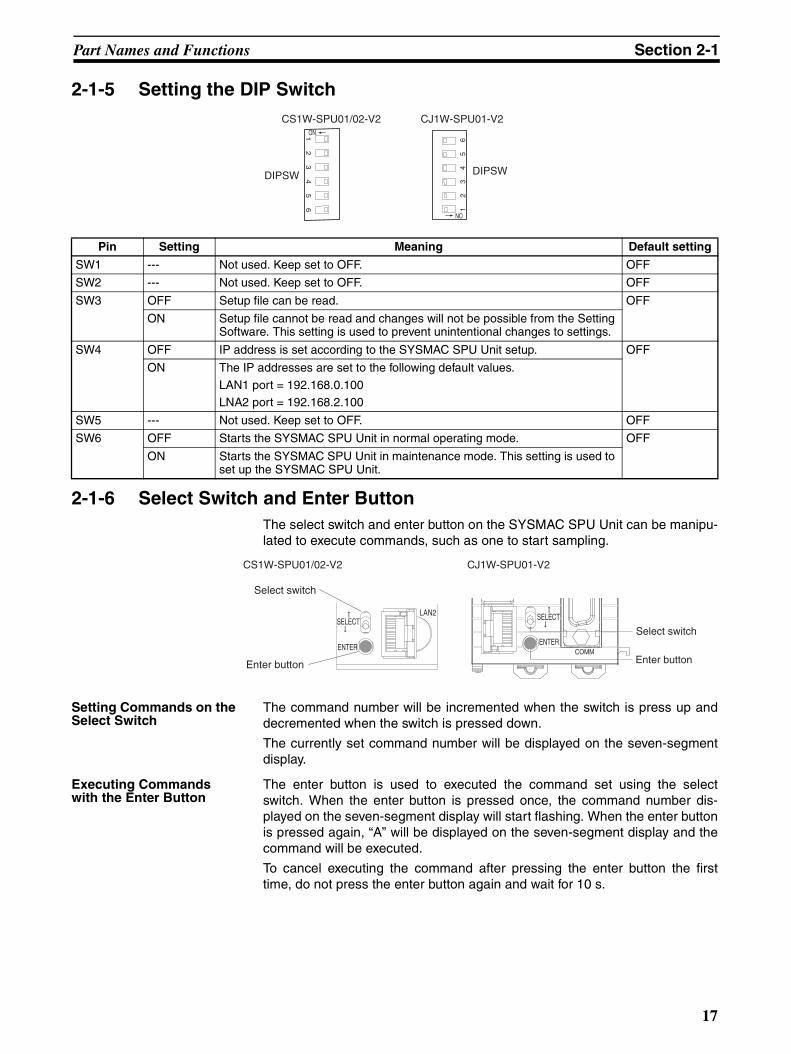
2-1-5 Setting the DIP Switch
2-1-6 Select Switch and Enter ButtonThe select switch and enter button on the SYSMAC SPU Unit can be manipu-lated to execute commands, such as one to start sampling.
Setting Commands on the Select Switch
The command number will be incremented when the switch is press up anddecremented when the switch is pressed down.
The currently set command number will be displayed on the seven-segmentdisplay.
Executing Commands with the Enter Button
The enter button is used to executed the command set using the selectswitch. When the enter button is pressed once, the command number dis-played on the seven-segment display will start flashing. When the enter buttonis pressed again, “A” will be displayed on the seven-segment display and thecommand will be executed.
To cancel executing the command after pressing the enter button the firsttime, do not press the enter button again and wait for 10 s.
12
34
56
ON
12
34
56
ON
DIPSW
CS1W-SPU01/02-V2 CJ1W-SPU01-V2
DIPSW
Pin Setting Meaning Default setting
SW1 --- Not used. Keep set to OFF. OFF
SW2 --- Not used. Keep set to OFF. OFF
SW3 OFF Setup file can be read. OFF
ON Setup file cannot be read and changes will not be possible from the Setting Software. This setting is used to prevent unintentional changes to settings.
SW4 OFF IP address is set according to the SYSMAC SPU Unit setup. OFF
ON The IP addresses are set to the following default values.
LAN1 port = 192.168.0.100LNA2 port = 192.168.2.100
SW5 --- Not used. Keep set to OFF. OFF
SW6 OFF Starts the SYSMAC SPU Unit in normal operating mode. OFF
ON Starts the SYSMAC SPU Unit in maintenance mode. This setting is used to set up the SYSMAC SPU Unit.
Select switch
Enter button
Select switch
Enter buttonCOMM
LAN2
CS1W-SPU01/02-V2 CJ1W-SPU01-V2
17

Part Names and Functions Section 2-1
The main commands are listed below. Refer to Section 6 Executing Com-mands in the SPU-Console Ver. 2.0 Operation Manual (Cat. No. V237).
2-1-7 Starting CPU Unit Operation Immediately upon Power Application If a SYSMAC SPU Unit is mounted to a PLC, a minimum of one second isrequired for SYSMAC SPU Unit initialization, and the CPU Unit will remain onstandby until initialization has been completed. This means that the CPU Unitwill not start operation when the power supply is turned ON even if the startupmode of the CPU Unit is set to RUN or MONITOR mode.
When using a CS1-H CPU Unit, the recognition retry switch on the SYSMACSPU Unit can be turned ON to omit waiting for the completion of initializationand start operation of the CPU Unit as soon as the power supply is turnedON. If this is done, the SYSMAC SPU Unit will initially not participate in PLCoperation.
Note With the CJ1W-SPU01-V2, the recognition retry function is always ON, and isnot a switch. To use this function, however, the Startup Condition setting in thePLC Setup for the CS1-H, CJ1-H, or CJ1M CPU Unit must be changed toDon’t Wait. Use the following procedure.
Command number
Command Function
01 Start basic collection Starts collecting data for the basic collection pat-tern.
02 Stop basic collection Stops collecting data for the basic collection pat-tern.
03 Save the sampled data
Saves the sampled data file and settings file in a ZIP file.
04 Clear the sampled data
Deletes contents of the data file.
05 Display the IP address (LAN1)
Displays the IP address of LAN1 on the seven-segment display.
06 Display the IP address (LAN2)
Displays the IP address of LAN2 on the seven-segment display.
07 Display the unit name
Displays the name of the Unit on the seven-seg-ment display.
08 Display the FINS address
Displays the FINS address of the Ethernet Com-munications Unit on the seven-segment display.
09 Display of Memory Card used space (%)
Displays the percentage of the Memory Card capacity that has been used.
10 Error display Displays any errors that exist.
11 Forced clear of error Clears the record of any errors that exist.
18

Part Names and Functions Section 2-1
1,2,3... 1. Turn ON the recognition retry switch on the back of the SYSMAC SPU Unit.
If the CPU Unit is in RUN or MONITOR mode after the power supply isturned ON, operation will depend on the setting of the recognition retry but-ton as follows:
OFF: CPU Unit will remain on standby until initialization of the SYSMACSPU Unit has been completed.
ON: The CPU Unit will not go on standby and execution of the ladder pro-gram will be started. This function can be used only for a CS1-H CPUUnit.
This operation is not required with the CJ1W-SPU01-V2, for which recognitionretry processing is always ON.
Note Keep this switch turned OFF when the SYSMAC SPU Unit is mounted underany CPU Unit other than a CS1-H CPU Unit. If this switch is turned ON forother CPU Units, a unit number duplication error will occur.
2. For both the CS1W-SPU01/SPU02-V2 and the CJ1W-SPU01-V2, set thefollowing setting in the PLC Setup from the CX-Programmer.
Set PLC Setup - Execution Settings - Startup Condition to Don’t Wait.
For details on the startup condition, refer to 7-1-2 PLC Setup Settings inthe CS Series PLC Operation Manual (Cat. No. W339) and in the CJ Se-ries PLC Operation Manual (Cat. No. W393).
Back of Unit
Recognition retry button
(Default: OFF)
ON
19

Mounting to the Backplane Section 2-2
2-1-8 DimensionsCS1W-SPU01-V2 and CS1W-SPU02-V2
CJ1W-SPU01-V2
2-2 Mounting to the Backplane
CS1W-SPU01/SPU02-V2
The SYSMAC SPU Unit is used mounted to the CPU Backplane. Refer to theCS Series PLC Operation Manual (Cat. No. W339) for instructions on mount-ing to the Backplane.
The SYSMAC SPU Unit must be counted as a CS-series CPU Bus Unit. Amaximum of 16 CS-series CPU Bus Units can be mounted to one PLC.
After mounting the SYSMAC SPU Unit to the Backplane and setting the unitnumber, turn ON the power supply to the PLC and create the I/O tables. Use aProgramming Device, such as a Programming Console or the CX-Program-mer, to create the I/O tables.
Note The maximum current consumption for CS1W-SPU01-V2 and CS1W-SPU02-V2 SYSMAC SPU Units is 560 mA and 700 mA respectively. Make sure that
10135
130
20 Unit: mm
51
94.8
659Unit: mm
20

Connecting the LAN Cable Section 2-3
the total current consumption of all the Units mounted to the same CPU Back-plane or Expansion Backplane does not exceed the maximum output capacityof the Power Supply Unit.
CJ1W-SPU01-V2 Connect the SYSMAC SPU Unit horizontally with the other Units. For detailson connecting Units together, refer to the CJ Series PLC Operation Manual(Cat. No. W393).
When mounting other CJ-series CPU Bus Units at the same time, the totalnumber of CJ-series CPU Bus Units must not exceed 16.
After the Units have been connected together and the unit numbers set, turnON the power supply to the CPU Unit.
Note The maximum current consumption for an CJ1W-SPU01-V2 SYSMAC SPUUnit is 560 mA. Make sure that the total current consumption of all the Unitsmounted to the same CPU Backplane or Expansion Backplane does notexceed the maximum output capacity of the Power Supply Unit.
2-3 Connecting the LAN CableThis section describes how to connect the LAN cable.
Connect a LAN cable conforming to 10Base-T or 100Base-TX to the LAN1port on the SYSMAC SPU Unit.
Note Use a 100Base-TX-conforming cable when connecting with 100Base-TXEthernet.
2-4 Connecting the Power Failure Signal
CS1W-SPU01/SPU02-V2
Connect the power failure signal output line from a UPS or other device to thepower failure input terminals on the SYSMAC SPU Unit.
Note Tighten the cable screws to a torque of 0.3 N·m.
Signal Input Specifications
Item Specification
Rated input voltage 24 VDC (+10% / −15%)
Input impedance 2 kΩInput current 10 mA (typical)
ON voltage 17.4 V min.
OFF voltage 5 V max.
Signals
IN
COM
MC1.5/2-STF-3.81
(Phoenix Contact)
Inte
rnal
circ
uits
2 KΩ
510 Ω
IN
COM
24 VDC
Input indicator
21
Connecting the Power Failure Signal Section 2-4
Uninterruptive Power Supply for Checking Operation
• BU70XS (OMRON) operating temperature range: 0 to 40°C• BU606F (OMRON) operating temperature range: 0 to 55°C
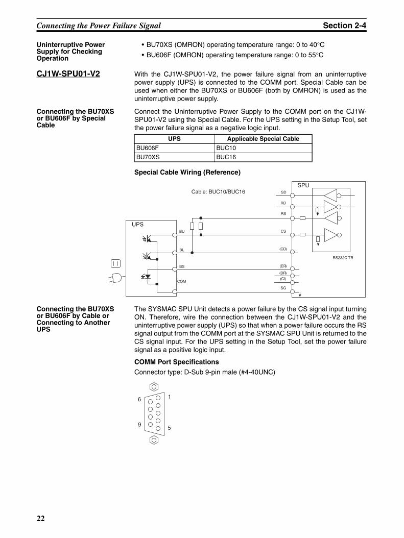
CJ1W-SPU01-V2 With the CJ1W-SPU01-V2, the power failure signal from an uninterruptivepower supply (UPS) is connected to the COMM port. Special Cable can beused when either the BU70XS or BU606F (both by OMRON) is used as theuninterruptive power supply.
Connecting the BU70XS or BU606F by Special Cable
Connect the Uninterruptive Power Supply to the COMM port on the CJ1W-SPU01-V2 using the Special Cable. For the UPS setting in the Setup Tool, setthe power failure signal as a negative logic input.
Special Cable Wiring (Reference)
Connecting the BU70XS or BU606F by Cable or Connecting to Another UPS
The SYSMAC SPU Unit detects a power failure by the CS signal input turningON. Therefore, wire the connection between the CJ1W-SPU01-V2 and theuninterruptive power supply (UPS) so that when a power failure occurs the RSsignal output from the COMM port at the SYSMAC SPU Unit is returned to theCS signal input. For the UPS setting in the Setup Tool, set the power failuresignal as a positive logic input.
COMM Port Specifications
Connector type: D-Sub 9-pin male (#4-40UNC)
UPS Applicable Special Cable
BU606F BUC10
BU70XS BUC16
UPS BU
SPU
COM
RS232C TR
CS
(ER)
SG
RS
(CD) BL
BS
RD
SD
(DR)
(CI)
Cable: BUC10/BUC16
1
5
6
9
22

Handling a PC Card or Memory Card Section 2-5
Connector Pin Arrangement
Connection Example 1: Connecting the BU606F with Cable
Connection Example 2: Connecting the BU70XS with Cable
2-5 Handling a PC Card or Memory Card
2-5-1 CS1W-SPU01/SPU02-V2
Inserting a PC Card This section describes how to insert a PC card into the PC card slot on theSYSMAC SPU Unit.
1,2,3... 1. Loosen the screw on the card holder and move the holder out of the way.
2. Press the PC card firmly to the back of the card slot.
Note Be sure the PC card is facing the correct direction.
“PC” will flash on the seven-segment display and the card indicator willlight when the PC card can be used.
Pin No. Abbrev. Signal name I/O
1 NC Not used. ---
2 RD Receive Data Input
3 SD Send Data Output
4 NC Not used. ---
5 SG Signal Ground ---
6 NC Not used. ---
7 RS Request to Send Output
8 CS Clear to Send Input
9 NC Not used. ---
Shell FG Shield
UPS
SPU
RS232C TR
Pin 2: BU
Pin 7: RS
Pin 8: CS
Pin 4: COM
Pin 8: BU
Pin 7: RS
Pin 8: CS
Pin 5: COM
UPS
SPU
RS232C TR
23
Handling a PC Card or Memory Card Section 2-5
3. Place the card holder on the PC card and tighten the screw on the cardholder.
Removing a PC Card This section describes how to remove a PC card from the PC card slot on theSYSMAC SPU Unit.
1,2,3... 1. Press the card button for at least 2 seconds.
“PC” will flash on the seven-segment display and the card indicator will goout when the PC card can be removed.
2. Loosen the screw on the card holder and move the holder out of the way.
3. Make sure that the card indicator is not lit and then press the card eject but-ton.
4. Remove the PC card from the PC card slot.
Formatting a PC Card This section describes how to format a PC card for use with the SYSMACSPU Unit.
A PC card can also be used if it is formatted on a personal computer using theFAT32 format.
1,2,3... 1. Insert the PC card as described above in Inserting a PC Card.
2. Be sure that the card indicator is lit and then press the select switch to se-lect command 31.
3. Press the enter button once. “31” will flash on the seven-segment display.
4. Press the enter button again.
“PC” will flash on the seven-segment display while the PC card is being for-matted. When formatting has been completed, “- -” (hyphens) will be dis-played on the seven-segment display.
2-5-2 CJ1W-SPU01-V2
Inserting a Memory Card
This section describes how to insert a Memory Card into the Memory Cardslot on the SYSMAC SPU Unit.
1,2,3... 1. Remove the card cover.
2. Press the Memory Card firmly to the back of the card slot.
Note Be sure the Memory Card is facing the correct direction.“PC” will flash on the seven-segment display and the card indicator will lightwhen the PC card can be used.
3. Replace the card cover.
Removing a Memory Card
This section describes how to remove a Memory Card from the Memory Cardslot on the SYSMAC SPU Unit.
1,2,3... 1. Press the card button for at least 2 seconds.“PC” will flash on the seven-segment display and the card indicator will goout when the Memory Card can be removed.
2. Remove the card cover.
3. Make sure that the card indicator is not lit and then press the card eject but-ton.
4. Remove the Memory Card from the Memory Card slot.
24

Initial Settings for the SYSMAC SPU Unit Section 2-6
Formatting a Memory Card
This section describes how to format a Memory Card for use with the SYS-MAC SPU Unit.
A Memory Card can also be used if it is formatted on a personal computerusing the FAT32 format.
1,2,3... 1. Insert the Memory Card as described above in Inserting a Memory Card.
2. Be sure that the card indicator is lit and then press the select switch to se-lect command 31.
3. Press the enter button once. “31” will flash on the seven-segment display.
4. Press the enter button again. “PC” will flash on the seven-segment displaywhile the Memory Card is being formatted. When formatting has beencompleted, “- -” (hyphens) will be displayed on the seven-segment display.
2-6 Initial Settings for the SYSMAC SPU UnitInitial software settings must be made to use the SYSMAC SPU Unit. To makethe initial settings, network parameters are set, product information is regis-tered, and system data is transferred.
Initial settings are made using the Initial Setting Wizard in the SPU-ConsoleBasic Software installed on a personal computer. For details, refer to Section3 Initial Settings of the SYSMAC SPU Unit in the SPU-Console Ver. 2.1 Oper-ation Manual (Cat. No. V237).
25
Initial Settings for the SYSMAC SPU Unit Section 2-6
26

27
SECTION 3Troubleshooting and Maintenance
This section provides maintenance and inspection information.
3-1 Seven-segment Display . . . . . . . . . . . . . . . . . . . . . . . . . . . . . . . . . . . . . . . . . . 28
3-2 Restrictions and Precautions . . . . . . . . . . . . . . . . . . . . . . . . . . . . . . . . . . . . . . 29
3-3 Inspection and Unit Replacement Precautions . . . . . . . . . . . . . . . . . . . . . . . . 32
3-3-1 Inspections . . . . . . . . . . . . . . . . . . . . . . . . . . . . . . . . . . . . . . . . . . . . 32
3-3-2 Unit Replacement Precautions . . . . . . . . . . . . . . . . . . . . . . . . . . . . . 33
3-4 Restarting the SYSMAC SPU Unit. . . . . . . . . . . . . . . . . . . . . . . . . . . . . . . . . 33

Seven-segment Display Section 3-1
3-1 Seven-segment Display
Refer to the descriptions of the commands in the SYSMAC WS02-SPTC1-V2SPU-Console Ver. 2.1 Operation Manual (Cat. No. V237) for details on theCONFIRM FTP CONNECTION command for FTP settings.
Seven-segment display Meaning
03 to 67 Lit The SYSMAC SPU Unit is operating.
-S Lit The SYSMAC SPU Unit is idle. (Sampling Mode)
-D Lit The SYSMAC SPU Unit is idle. (Data Storage Mode)
--- Flashing The sampling program is running in the SYS-MAC SPU Unit.
PC Flashing PC card or Memory Card insertion processing is being performed. PC card or Memory Card removal processing is being performed.
NG Flashing PC card or Memory Card removal processing failed and use of the PC card or Memory Card was forcibly disabled. The PC card or Memory Card can be removed.
NM Lit The SYSMAC SPU Unit was started in Mainte-nance Mode. (Pin 6 on the DIP switch is ON.)
N2 Lit Automatically obtaining an IP address failed. Check to see if the LAN cable is connected cor-rectly and if the system is set up to obtain addresses from the DHCP.
41 Lit Turn OFF DIP switch pins 5 and 6.
66 Lit Turn OFF DIP switch pin 5.
Clockwise rotation Periodic data collection or sampling is being per-formed.
P<number>/PE Flashing Data collection or sampling is being set.
AA Lit Data collection or sampling data is being saved.
C<number>/CE Flashing Data collection or sampling data is being cleared.
B<number>/BE Flashing Data collection or sampling settings are being backed up.
M<number>/ME Flashing Operating Mode is being changed.
R<number>/RE Flashing Data collection or sampling settings are being restored.
T<number>/TE Flashing System check values are being optimized.
U<number>/UE Flashing SYSMAC SPU Unit settings are being changed.
SD/RV/00 to 99 Lit The number of the setting is displayed in the upper digit and the item being checked is dis-played in the lower digit when executing the CONFIRM FTP CONNECTION command for FTP settings (command 61).
0E to 9E Flashing The number of a setting that may not be correct when executing the CONFIRM FTP CONNEC-TION command for FTP settings (command 61) is displayed in the upper digit and "E" is dis-played in the lower digit to indicate an error.
28

Restrictions and Precautions Section 3-2
3-2 Restrictions and PrecautionsA) Never restart the SYSMAC SPU Unit or turn OFF the power supply to the
PLC when changing settings such as the data collection (sampling) set-tings. “P1,” “P2,” … “PE” will be displayed on the 7-segment display whensampling settings are being changed. If the SYSMAC SPU Unit isrestarted or the power supply is turned OFF when sampling settings arebeing changed, the system or files being changed may be corrupted.
B) Sampling Capacity
The sampling capacity of the SYSMAC SPU Unit varies with the followingfactors:
• Sampling Operating Mode (Sampling Mode or Data Storage Mode)
• Sampling period
• Quantity of variables recorded as sampling data
• Number of files used to save sampled data
• Writing speed of media where sampling data is saved
• Number of samplings that are set
• CPU Unit cycle time
There are no predetermined restrictions on these factors for SYSMACSPU Unit sampling. It is assumed that the required sampling will be testedon the actual system to confirm applicability. We recommend that theabove factors be studied and tested sufficiently before using the samplingfunction in an actual system to determine suitable settings.
Examples:
• When precise sampling periods are required, use Sampling Mode.
• To shorten the sampling period:
• Reduce the quantity of sampling data.
• Reduce the number of sets of data being sampled.
• Use a faster storage media.
• To record a large volume of sampling data:
• Increase the sampling period.
C) Time Compensation Function
The SYSMAC SPU Unit reads the time from the CPU Unit at startup andsets its own timer. If the two times differ by more than 1 second during op-eration, one of the following operations is performed.
• If the time difference is 5 seconds or less, the time in the SYSMAC SPUUnit is gradually shifted to agree with the CPU Unit’s time.
• If the time difference is more the 5 seconds, the SYSMAC SPU Unit’s timeis reset to agree with the CPU Unit’s time.
D) Realtime Sampling Characteristic
With realtime sampling, sampling is performed by the SYSMAC SPU Unitas much as possible according to the sampling settings. The following con-ditions, however, may prevent sampling from being performed at complete-ly fixed intervals. Be sure to consider possible affects of this on theapplication in advance.
• Offset between the timer accuracy and the time of the SYSMAC SPUUnit
29
Restrictions and Precautions Section 3-2
• Changes in the sampling period during compensation by the time com-pensation function with the CPU Unit
• Delays caused by system traffic, particularly concentrated access tothe storage media
To handle these problems, the SYSMAC SPU Unit provides time stampswith sampling data. We recommend that tests be performed in advance sothat the results of sampling are not radically different from those for fixed-interval sampling.
E) Relationship to Cycle Time of CPU Unit
• The SYSMAC SPU Unit collects I/O memory data during the I/O re-fresh interval of the CPU Unit. The cycle time of the CPU Unit, howev-er, will be longer when the SYSMAC SPU Unit is sampling I/O memory.The affect of the SYSMAC SPU Unit on the CPU Unit cycle time de-pends on the series of CPU Unit, as given below.
• CS1 CPU Units: 1.0 ms + No. of words sampled × 1 µs
• CS1-H CPU Units: 0.2 ms + No. of words sampled × 0.8 µs
• CJ1-H CPU Units: 0.2 ms + No. of words sampled × 0.8 µs
• CJ1M CPU Units: 0.2 ms + No. of words sampled × 0.8 µs
• The sampling period of the SYSMAC SPU Unit cannot be shorter thanthe cycle time of the CPU Unit. This is because the SYSMAC SPU Unituses the I/O refresh period of the CPU Unit’s cycle time to collect data.If a sampling period is set that is shorter than the cycle time of the CPUUnit, I/O memory will be sampled at an interval equivalent to the cycletime of the CPU Unit.
• When the CPU Unit is in PROGRAM mode, the CPU Unit’s cycle timewill be longer so it may not be possible to read the data within the settime interval.
F) Data Collection (Sampling) File Size
• The maximum size of one data collection (sampling) file is 2 GB.
• If sufficient space cannot be secured in advance for the data collection(sampling) settings, the disk may become full during data collection(sampling), causing an error.
• Depending on the file sizes, time may be required to change data col-lection (sampling) settings to secure space in advance.
• When saving data without a specified number of records, the file sizewill continuously increase until data collection is stopped. Be sure thatthere is enough available memory for the data.
• The file cannot be copied if there is insufficient space available even ifthe copy option has been selected in Data Storage Mode.
G) A long period of time may be required to search for a SYSMAC SPU Uniton the Windows network depending on the proxy server settings in Win-dows Internet Explorer. Change the Windows proxy server setting to oneof the following settings from Internet Explorer: Tools - Internet Options -Connections Tab - LAN Settings - Proxy Server.
• Clear the selection to use the proxy server for LAN.
• Click the Details Button and set the IP address of the SYSMAC SPUUnit so that the proxy server is not used for it.
30

Restrictions and Precautions Section 3-2
H) Executing SYSMAC SPU Unit Commands from the CPU Unit
The SYSMAC SPU Unit with unit version 2.0 or later supports functionsthat allow specific words in the CPU Bus Unit Area of the CPU Unit to beused to specify commands to be executed and to provide SYSMAC SPUUnit status in the CPU Unit. These words are automatically read and writ-ten by the SYSMAC SPU Unit. Be sure to allocate words in the CPU Unitto the SYSMAC SPU Unit carefully so that the control program will not beaffected adversely. To maintain compatibility, the status area that was setwith SYSMAC SPU Units with unit version 1.3 or earlier can also be used.(The status area is set using Status Area Settings on the SPU-Console’sVariable Settings Menu.)
I) Never delete the files and folders in the Journal folder, which is a Win-dows network-shared folder. Data collection (sampling) may not be possi-ble if these folders or files are deleted. If any of these folder or files isdeleted, perform the procedure to set data collection (sampling) from theSPU-Console.
J) The SYSMAC SPU Unit operates on UTC (coordinated universal time), sothe creation date of the network-shared folder may not be appropriate forthe local time. Before using the SYSMAC SPU Unit, change the time zonein the SPU-Console’s Unit settings.
K) When using an FTP server, select an FTP server that supports the FTPcommands in the FTP command list. Refer to the SYSMAC WS02-SPTC1-V2 SPU-Console Ver. 2.1 Operation Manual (Cat. No. V237) for alist of the FTP commands.
31

Inspection and Unit Replacement Precautions Section 3-3
3-3 Inspection and Unit Replacement PrecautionsPeriodic inspections are required to ensure using the SYSMAC SPU Unitunder optimum conditions.
3-3-1 InspectionsInspection Items The main functional components of the SYSMAC SPU Unit are semiconduc-
tors. There are no components that will stop functioning all of a sudden whena specific life is reached, but the components may deteriorate depending onthe operating environment. Periodic inspections are thus very important.
Inspection Period
Inspections should normally be performed every six months to one year. Theinspection period must, however, be based on the ambient conditions.
Inspection Items
Corrective measures must be performed to maintain the following items withinthe criteria.
Tools Required for Inspection
The following items are used during inspection.
Items Normally Required
Both flat-blade and Phillips screwdrivers
Circuit tester or voltage meter
Industrial alcohol and cotton cloth
Items Sometimes Required
Synchroscope
Oscilloscope with pen recorder
Thermometer and hygrometer
Inspection Items
Inspection Criteria
Ambient envi-ronment
Inspect the ambient temperature and the temperature inside the control panel.
0 to 55°C
Inspect the ambient humidity and the humidity inside the control panel.
10% to 90% (with no con-densation)
Inspect for the collection of dust. There must be no dust.
Installation Inspect the mounting of the SYSMAC CPU Unit.
The Unit must not be loose.
Inspect the LAN cables to be sure they are inserted properly.
The Unit must not be loose.
Inspect the LAN cables for abnormali-ties.
There must be no abnor-malities in the exterior appearance.
Inspect the PC card holder to be sure it is secure.
The Unit must not be loose.
32

Restarting the SYSMAC SPU Unit Section 3-4
3-3-2 Unit Replacement PrecautionsIf a faulty SYSMAC SPU Unit is discovered during inspections, the SYSMACSPU Unit will need to be replaced. Observe the following precautions whenreplacing a SYSMAC SPU Unit.
Always turn OFF the power supply before replacing the Unit.
After replacing the Unit, check the new Unit to be sure it is operating correctly.
• When returning a fault Unit for repairs, provide as many details on thenature of the problem as possible, attach the information to the Unit, andreturn it to your OMRON representative.
• If contact faults are discovered, use a cotton cloth wetted in industrial-quality alcohol to clean the contacts and then remove all lint from the con-tacts before mounting the Unit.
All SYSMAC SPU Unit parameters can be backed up in the Memory Card byexecuting command number 21 (Save Settings to Memory Card). This file canthen be read after replacing the SYSMAC SPU Unit by executing commandnumber 22 (Read Settings from Memory Card) to easily make the proper set-tings for any Unit.
3-4 Restarting the SYSMAC SPU Unit The SYSMAC SPU Unit can be restarted by itself without turning OFF thepower supply to the CPU Unit. For some applications, it is difficult to turn OFFthe power supply to the entire PLC. The methods described here can be usedto restart only the SYSMAC SPU Unit.
There are three different ways that can be used to restart the SYSMAC SPUUnit.
1,2,3... 1. Execute SYSMAC SPU Unit command number 12 (Restart Unit). This is the most recommended method.
2. Turn ON the CPU Bus Unit Restart Bit allocated to the SYSMAC SPU Unitin the Auxiliary Area in the CPU Unit.If you use this method, be careful not to restart the wrong Unit by turningON the wrong bit.
3. Turn ON pin 6 on the DIP switch on the SYSMAC SPU Unit and press theENTER button for a few seconds. “NM” will be displayed on the 7-segment display after restarting. Turn OFFpin 6 on the DIP switch and then execute SYSMAC SPU Unit commandnumber 12 (Restart unit). This method can be used to force-restart the SYSMAC SPU Unit. Usingthis method is not recommended because all processing for saving sam-pling data to files will be force-ended.
33

Restarting the SYSMAC SPU Unit Section 3-4
34

Index
Aapplications precautions, xx
BBackplane, 20
Ccard button, 14, 15
card eject button, 14
card holder, 14
card indicator, 14
commands, 17
CPU Unit
standby, 18
CPU Unit cycle time
relationship, 12
crimp terminals, xxi
cycle time, 12
Ddata collection, 3data collection patterns, 8dimensions, 20
DIP switch, 17
EEC Directives, xxiii
electromagnetic fields, xx
EMC Directives, xxiii
EMI Standard, xxiii
EMS Standard, xxiii
enter button, 17
Iindicators, 14
card, 14
LAN, 14
PF-IN, 14
initial settings, 25
inspections, 32
installation
location, xix
LLAN cable, 21
LAN indicator, 14
locking devices
precautions, xxi
Low Voltage Directive, xxiii
MMemory Cards, 6
Nnoise, xx
Oonline editing, xix
operating environment
precautions, xix
Ppart names, 14
PC card slot, 23, 24
PF-IN indicator, 14
PF-IN terminals, 15
power failure signal
connecting, 21
power supply, xx
precautions, xx, xxi
precautions, xvii, 29
applications, xx
general, xviii
operating environment, xix
power supply, xx
safety, xix
Unit replacement, 32
product configuration, 6
35

Index
Rradioactivity, xx
Read Settings from Memory Card, 33
realtime characteristics, 11
recognition retry switch, 18
replacing Units
precautions, xxi
restarting, 33
restrictions, 29
Ssafety precautions, xix
sampling
specifications, 11
sampling file size, 12
sampling settings
backing up, 33
restoring, 33
Save Settings to Memory Card, 33
select switch, 17
seven-segment display, 16, 28
short-circuits
precautions, xx
signals
precautions, xix
specifications
realtime characteristics, 11
sampling, 11
SPU-Console, 10
SYSMAC SPU Unit, 6SPU-Console, 6
specifications, 10
Startup Condition, 18
static electricity, xx
Tterminal blocks, xix
transferring programs, xix
Uunit number, 16
duplication error, 19
switch, 16
Unit replacement
precautions, 32
UPS, 21
36

Revision History
A manual revision code appears as a suffix to the catalog number on the front cover of the manual.
The following table outlines the changes made to the manual during each revision. Page numbers refer to theprevious version.
Revision code Date Revised content
01 June 2007 Original production
02 November 2008 Added information on improvements to the recipe function and FTP communica-tions.
Cat. No. V236-E1-02
Revision code
37

Revision History
38


OMR
OMRIndus
RegioOMROWegaThe NTel: (3
ContrPLC DShiokoKyoto,Tel: (8
Authorized Distributor:ON Corporationtrial Automation Company
nal Headquarters
OMRON ELECTRONICS LLCOne Commerce Drive Schaumburg, IL 60173-5302 U.S.A.Tel: (1) 847-843-7900/Fax: (1) 847-843-7787
OMRON ASIA PACIFIC PTE. LTD.No. 438A Alexandra Road # 05-05/08 (Lobby 2), Alexandra Technopark, Singapore 119967Tel: (65) 6835-3011/Fax: (65) 6835-2711
OMRON (CHINA) CO., LTD.
ol Devices Division H.Q.ivisionji Horikawa, Shimogyo-ku, 600-8530 Japan1) 75-344-7084/Fax: (81) 75-344-7149
In the interest of product improvement, specifications are subject to change without notice.
Cat. No. V236-E1-02ON Industrial Automation Global: www.ia.omron.comPrinted in Japan
1108
N EUROPE B.V.laan 67-69-2132 JD Hoofddorpetherlands1)2356-81-300/Fax: (31)2356-81-388
Room 2211, Bank of China Tower, 200 Yin Cheng Zhong Road, PuDong New Area, Shanghai, 200120, ChinaTel: (86) 21-5037-2222/Fax: (86) 21-5037-2200
© OMRON Corporation 2007 All Rights Reserved.