SYSMAC CJ-series CJ1M CPU Units (with Ethernet … · SYSMAC CJ-series CJ1M CPU Units (with...
13
CSM_CJ1M-CPU-ETN_DS_E_2_2 1 SYSMAC CJ-series CJ1M CPU Units (with Ethernet function) CJ1M-CPU1@-ETN A Micro CJ1M CPU Unit with Built-in Ethernet Newly Released! • SYSMAC CJ-series CPU Unit with the functionality of an Ethernet Unit. Features • Compact 90 × 65 mm (H × D) dimensions are first class in the industry. • SYSMAC CJ-series CPU Unit with the functionality of an Ethernet Unit. • The CPU functional element has the same functionality as a CJ1M-CPU11/12/13. The enables effective usage of legacy applications. • High-capacity Memory Cards up to 128 MB can be installed, and used to backup the program and system settings, or log customer data. • The large instruction set can support diverse applications. Four types of programming are supported (ladder, structured text, sequential function charts, and instruction lists), with approximately 400 instructions and 800 instruction variations. • These CJ-series CPU Units support structured programming using function blocks, which can improve the customer's program development resources. • The various protection functions provide improved security to protect valuable software resources and property. • The CPU Units are compatible with the CX-One Integrated Tool Package. Information for each component can be linked, and the system's data can be integrated into one database. The software can provide total support from PLC settings to network startup. CJ1M-CPU11-ETN
Transcript of SYSMAC CJ-series CJ1M CPU Units (with Ethernet … · SYSMAC CJ-series CJ1M CPU Units (with...

CSM_CJ1M-CPU-ETN_DS_E_2_2
1
SYSMAC CJ-series CJ1M CPU Units (with Ethernet function)
CJ1M-CPU1@-ETNA Micro CJ1M CPU Unit with Built-in Ethernet Newly Released!• SYSMAC CJ-series CPU Unit with the functionality of
an Ethernet Unit.
Features• Compact 90 × 65 mm (H × D) dimensions are first class in the industry.• SYSMAC CJ-series CPU Unit with the functionality of an Ethernet Unit.• The CPU functional element has the same functionality as a CJ1M-CPU11/12/13. The enables effective usage of legacy applications.• High-capacity Memory Cards up to 128 MB can be installed, and used to backup the program and system settings, or log customer data.• The large instruction set can support diverse applications. Four types of programming are supported (ladder, structured text, sequential function
charts, and instruction lists), with approximately 400 instructions and 800 instruction variations.• These CJ-series CPU Units support structured programming using function blocks, which can improve the customer's program development
resources.• The various protection functions provide improved security to protect valuable software resources and property.• The CPU Units are compatible with the CX-One Integrated Tool Package. Information for each component can be linked, and the system's data
can be integrated into one database. The software can provide total support from PLC settings to network startup.
CJ1M-CPU11-ETN
CJ1M-CPU1@-ETN
2
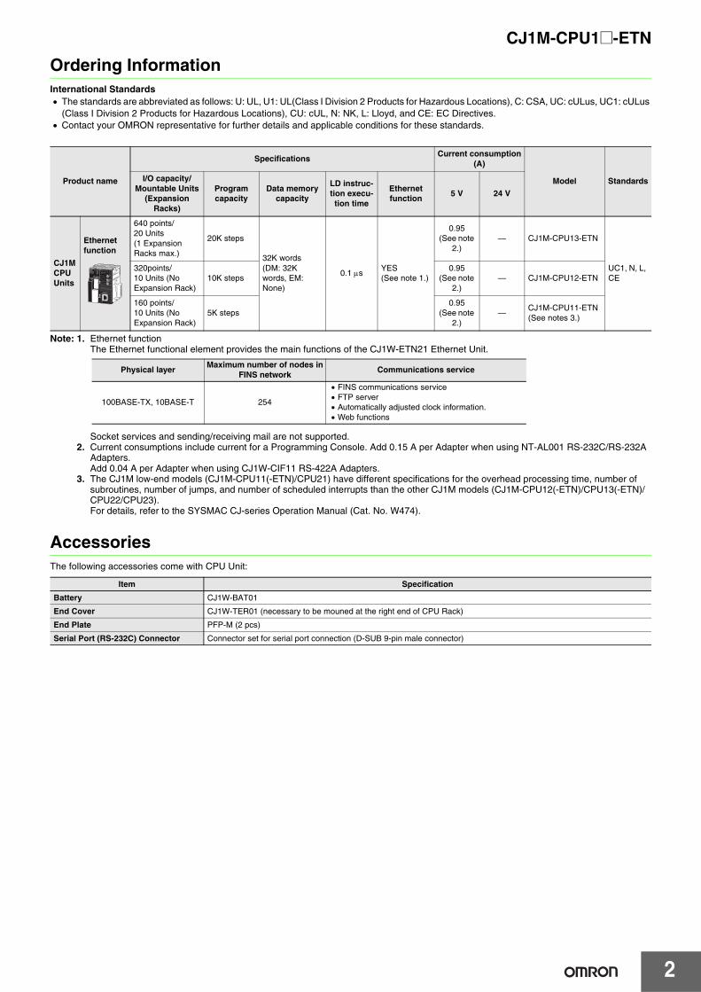
Ordering InformationInternational Standards• The standards are abbreviated as follows: U: UL, U1: UL(Class I Division 2 Products for Hazardous Locations), C: CSA, UC: cULus, UC1: cULus
(Class I Division 2 Products for Hazardous Locations), CU: cUL, N: NK, L: Lloyd, and CE: EC Directives.• Contact your OMRON representative for further details and applicable conditions for these standards.
Note: 1. Ethernet functionThe Ethernet functional element provides the main functions of the CJ1W-ETN21 Ethernet Unit.
Socket services and sending/receiving mail are not supported.2. Current consumptions include current for a Programming Console. Add 0.15 A per Adapter when using NT-AL001 RS-232C/RS-232A
Adapters.Add 0.04 A per Adapter when using CJ1W-CIF11 RS-422A Adapters.
3. The CJ1M low-end models (CJ1M-CPU11(-ETN)/CPU21) have different specifications for the overhead processing time, number of subroutines, number of jumps, and number of scheduled interrupts than the other CJ1M models (CJ1M-CPU12(-ETN)/CPU13(-ETN)/CPU22/CPU23). For details, refer to the SYSMAC CJ-series Operation Manual (Cat. No. W474).
AccessoriesThe following accessories come with CPU Unit:
Product name
SpecificationsCurrent consumption
(A)
Model StandardsI/O capacity/Mountable Units
(Expansion Racks)
Program capacity
Data memory capacity
LD instruc-tion execu-tion time
Ethernet function
5 V 24 V
CJ1M CPU Units
Ethernet function
640 points/20 Units(1 Expansion Racks max.)
20K steps
32K words(DM: 32K words, EM: None)
0.1 μsYES(See note 1.)
0.95 (See note
2.)— CJ1M-CPU13-ETN
UC1, N, L, CE
320points/10 Units (No Expansion Rack)
10K steps0.95
(See note 2.)
— CJ1M-CPU12-ETN
160 points/10 Units (No Expansion Rack)
5K steps0.95
(See note 2.)
—CJ1M-CPU11-ETN(See notes 3.)
Physical layerMaximum number of nodes in
FINS networkCommunications service
100BASE-TX, 10BASE-T 254
• FINS communications service• FTP server• Automatically adjusted clock information.• Web functions
Item Specification
Battery CJ1W-BAT01
End Cover CJ1W-TER01 (necessary to be mouned at the right end of CPU Rack)
End Plate PFP-M (2 pcs)
Serial Port (RS-232C) Connector Connector set for serial port connection (D-SUB 9-pin male connector)

3
CJ1M-CPU1@-ETN
Common Specifications
Item Specifications
Control method Stored program
I/O control method Cyclic scan and immediate processing are both possible.
Programming Languages Ladder Logic (LD), Sequential Function Charts (SFC), Structured Text (ST), and Mnemonic.
CPU processing mode Normal Mode or Peripheral Servicing Priority Mode
Instruction length 1 to 7 steps per instruction
Ladder instructions Approx. 400 (3-digit function codes)
Execution timeBasic instructions 0.10 μs min.
Special instructions 0.15 μs min.
Overhead timeCJ1M-CPU12-ETN/CPU13-ETN :CJ1M-CPU11-ETN :
0.5 ms min.0.7 ms min.
Unit connection method No Backplane: Units connected directly to each other.
Mounting method DIN Track (screw mounting not possible)
Maximum number of connectable Units
Total of 19 Units, including 9 Units on CPU Rack and 10 Units on one Expansion Rack.(The built-in Ethernet port on the CPU Unit must be allocated to a slots 0, and is counted as one Unit.
Maximum number of Expansion Racks
• CJ1M-CPU13-ETN: 1 max. (An I/O Control Unit is required on the CPU Rack and an I/O Interface Unit is required on the Expansion Rack.)
• CJ1M-CPU11-ETN/12-ETN:Expansion is not possible.
Number of tasks
288 (cyclic tasks: 32, interrupt tasks: 256)With CJ1-H or CJ1M CPU Units, interrupt tasks can be defined as cyclic tasks called extra cyclic tasks. Including these, up to 288 cyclic tasks can be used.Note 1. Cyclic tasks are executed each cycle and are controlled with TKON(820) and TKOF(821) instructions.
2. The following 4 types of interrupt tasks are supported.Power OFF interrupt tasks: 1 max.Scheduled interrupt tasks : 2 max.I/O interrupt tasks: 32 max.External interrupt tasks: 256 max.
Interrupt types
Scheduled Interrupts: Interrupts generated at a time scheduled by the CPU Units built-in timer.I/O Interrupts: Interrupts from Interrupt Input Units.Power OFF Interrupts (See note): Interrupts executed when the CPU Units power is turned OFF.External I/O Interrupts: Interrupts from the Special I/O Units or CPU Bus Units.Note: Not supported when the CJ1W-PD022 Power Supply Unit is mounted.
Calling subroutines from more than one task
Supported (called global subroutines).
CIO (Core I/O) Area
I/O Area
2,560: CIO 000000 to CIO 015915 (160 words from CIO 0000 to CIO 0159)The setting of the first word can be changed from the default (CIO 0000) so that CIO 0000 to CIO 0999 can be used.I/O bits are allocated to Basic I/O Units.
The CIO Area can be used as work bits if the bits are not used as shown here.
Link Area3,200 (200 words): CIO 10000 to CIO 119915 (words CIO 1000 to CIO 1199)Link bits are used for data links and are allocated to Units in Controller Link Systems.
CPU Bus Unit Area 6,400 (400 words): CIO 150000 to CIO 189915 (words CIO 1500 to CIO 1899)CPU Bus Unit bits store the operating status of CPU Bus Units. (25 words per Unit, 16 Units max.)
Special I/O Unit Area
15,360 (960 words): CIO 200000 to CIO 295915 (words CIO 2000 to CIO 2959)Special I/O Unit bits are allocated to Special I/O Units. (10 words per Unit, 96 Units max.)
Serial PLC Link Area (CJ1M CPU Units only)
1,440 (90 words): CIO 310000 to CIO 318915 (words CIO 3100 to CIO 3189)
DeviceNet Area
9,600 (600 words): CIO 320000 to CIO 379915 (words CIO 3200 to CIO 3799)DeviceNet bits are allocated to Slaves for DeviceNet Unit remote I/O communi-cations when the Master function is used with fixed allocations.
The following words are allocated to the Master function even when the DeviceNet Unit is used as a Slave.
Fixed allocation setting 1Outputs: CIO 3200 to CIO 3263
Inputs: CIO 3300 to CIO 3363
Fixed allocation setting 2Outputs: CIO 3400 to CIO 3463
Inputs: CIO 3500 to CIO 3563
Fixed allocation setting 3Outputs: CIO 3600 to CIO 3663
Inputs: CIO 3700 to CIO 3763
Fixed allocation setting 1Outputs: CIO 3370 (Slave to Master)Inputs: CIO 3270 (Master to Slave)
Fixed allocation setting 2Outputs: CIO 3570 (Slave to Master)
Inputs: CIO 3470 (Master to Slave)
Fixed allocation setting 3Outputs: CIO 3770 (Slave to Master)
Inputs: CIO 3670 (Master to Slave)

4
CJ1M-CPU1@-ETN
CIO (Core I/O) Area Internal I/O Area
4,800 bits (300 words): CIO 120000 to CIO 149915 (words CIO 1200 to CIO 1499)37,504 (2,344 words): CIO 380000 to CIO 614315 (words CIO 3800 CIO 6143)These bits in the CIO Area are used as work bits in programming to control program execution. They cannot be used for external I/O.
Work Area8,192 bits (512 words): W00000 to W51115 (W000 to W511)Controls the programs only. (I/O from external I/O terminals is not possible.)Note: When using work bits in programming, use the bits in the Work Area first before using bits from other areas.
Holding Area
8,192 bits (512 words): H00000 to H51115 (H000 to H511) Holding bits are used to control the execution of the program, and maintain their ON/OFF status when the PLC is turned OFF or the operating mode is changed.Note: The Function Block Holding Area words are allocated from H512 to H1535. These words can be used only for
the function block instance area (internally allocated variable area).
Auxiliary AreaRead only: 7,168 bits (448 words): A00000 to A44715 (words A000 to A447)Read/write: 8,192 bits (512 words): A44800 to A95915 (words A448 to A959)Auxiliary bits are allocated specific functions.
Temporary Area16 bits (TR0 to TR15)Temporary bits are used to temporarily store the ON/OFF execution conditions at program branches.
Timer Area 4,096: T0000 to T4095 (used for timers only)
Counter Area 4,096: C0000 to C4095 (used for counters only)
DM Area
32 Kwords: D00000 to D32767Used as a general-purpose data area for reading and writing data in word units (16 bits). Words in the DM Areamaintain their status when the PLC is turned OFF or the operating mode is changed.Internal Special I/O Unit DM Area: D20000 to D29599 (100 words × 96 Units)Used to set parameters for Special I/O Units.CPU Bus Unit DM Area: D30000 to D31599 (100 words × 16 Units) Used to set parameters for CPU Bus Units.
EM Area None
Index Registers
IR0 to IR15Store PLC memory addresses for indirect addressing. Index registers can be used independently in each task. One register is 32 bits (2 words).Setting to use index registers either independently in each task or to share them between tasks.
Task Flag Area
32 (TK0000 to TK0031)Task Flags are read-only flags that are ON when the corresponding cyclic task is executable and OFF when the corresponding task is notexecutable or in standby status.
Trace Memory 4,000 words (trace data: 31 bits, 6 words)
File Memory• Memory Cards: Compact flash memory cards can be used (MS-DOS format).• OMRON Memory Cards can be used.
Function Specifications
Constant cycle time 1 to 32,000 ms (Unit: 1 ms)
Cycle time monitoring Possible (Unit stops operating if the cycle is too long): 10 to 40,000 ms (Unit: 10 ms)
I/O refreshingCyclic refreshing, immediate refreshing, refreshing by IORF(097).Note: ORF(097) refreshes I/O bits allocated to Basic I/O Units and Special I/O Units.
Timing of special refreshing for CPU Bus Units
Data links for Controller Link Units remote I/O for DeviceNet Units, and other special refreshing for CPU Bus Units is performed at the following times:I/O refresh period and when the CPU BUS UNIT I/O REFRESH (DLNK(226)) instruction is executed.
I/O memory holding when changing operating modes
Depends on the ON/OFF status of the IOM Hold Bit in the Auxiliary Area.
Load OFFAll outputs on Output Units can be turned OFF when the CPU Unit is operating in RUN, MONITOR, or PROGRAM mode.
Timer/Counter PV refresh method
BCD or binary (CX-Programmer Ver. 3.0 or higher).
Input response time setting
Time constants can be set for inputs from Basic I/O Units.The time constant can be increased to reduce the influence of noise and chattering or it can be decreased to detect shorter pulses on the inputs.
Mode setting at power-up
Possible.Note: By default, the CPU Unit will start in RUN mode if a Programming Console is not connected.
Flash memory (CJ1-H and CJ1M CPU Units only)
• The user program and parameter area data (e.g., PLC Setup) are always backed up automatically in flash memory.(automatic backup and restore.)
• CPU Units with unit version 3.0 or later only:When downloading projects from CX-Programmer Ver. 5.0 or higher, symbol table files (including CX-Programmer symbol names, I/O comments), comment files (CX-Programmer rung comments, other comments), and program index files (CX-Programmer section names, section comments, or program comments) are stored in comment memory within the flash memory.
Item Specifications

CJ1M-CPU1@-ETN
5
Function Specifications
Memory Card functions
Automatically reading programs (autoboot) from the Memory Card when the power is turned ON.
Possible.
Program replacement during PLC operation
Possible.
Format in which data is stored in Memory Card
User program: Program file format PLC Setup and other parameters:Data file format I/O memory: Data file format (binary format), text format, or CSV format
Functions for which Memory Card read/write is supported
User program instructions, Programming Devices (including CX-Programmer and Programming Consoles), Host Link computers, AR Area control bits, easy backup operation
Filing Memory Card data and the EM (Extended Data Memory) Area can be handled as files.
DebuggingControl set/reset, differential monitoring, data tracing (scheduled, each cycle, or when instruction is executed), instruction error tracing, storing location generating error when a program error occurs.
Online editingUser programs can be overwritten in program-block units when the CPU Unit is in MONITOR or PROGRAM mode.This function is not available for block programming areas.With the CX-Programmer, more than one program block can be edited at the same time.
Program protectionOverwrite protection: Set using DIP switch.Copy protection: Password set using CX-Programmer or Programming Consoles.
Error checkUser-defined errors (i.e., user can define fatal errors and non-fatal errors)The FPD(269) instruction can be used to check the execution time and logic of each programming block.Note: FAL and FALS instructions can be used with the CJ1-H and CJ1M CPU Units to simulate errors.
Error logUp to 20 errors are stored in the error log. Information includes the error code, error details, and the time the error occurred.Note: CJ1M CPU Unit can be set so that user-defined FAL errors are not stored in the error log.
Serial communications
Built-in peripheral port: Programming Device (including Programming Console) connections, Host Links, NT Links, Serial Gateway (CompoWay/F master)Built-in RS-232C port: Programming Device (excluding Programming Console) connections, Host Links, no-protocol communications, NT Links, Modbus-RTU Slave, Serial Gateway (CompoWay/F master or Modbus master)
Serial Communications Unit (sold separately): Protocol macros, Host Links, NT Links
Clock
Provided on all models.
Note: Used to store the time when power is turned ON and when errors occur.
Power OFF detection time
AC Power Supply Unit: 10 to 25 ms (not fixed)DC Power Supply Unit PD025: 2 to 5 ms; PD022: 2 to 10 ms
Power OFF detection delay time
0 to 10 ms (user-defined, default: 0 ms)Note: Not supported when the CJ1W-PD022 Power Supply Unit is mounted.
Memory protection
Held Areas: Holding bits, contents of Data Memory and Extended Data Memory, and status of the counter Completion Flags and present values.Note: If the IOM Hold Bit in the Auxiliary Area is turned ON, and the PLC Setup is set to maintain the IOM Hold Bit
status when power to the PLC is turned ON, the contents of the CIO Area, the Work Area, part of the AuxiliaryArea, timer Completion Flag and PVs, Index Registers, and the Data Registers will be saved for up to 20 days.
Sending commands to a Host Link computer
FINS commands can be sent to a computer connected via the Host Link System by executing Network Communications Instructions from the PLC.
Remote programming and monitoring
Host Link communications can be used for remote programming and remote monitoring through a Controller Link System or Ethernet network.
Communicating across network levels
Remote programming and monitoring from Support Software and FINS message communications can be performed across different network levels, even for different types of network.Pre-Ver. 2.0 : Three levelsVersion 2.0 or later : Eight levels for Controller Link and Ethernet networks (See note.), three levels for other networks.Note: To communicate across eight levels, the CX-Integrator or the CX-Net in Programmer version 4.0 or higher must
be used to set the routing tables.
Storing comments in CPU Unit
I/O comments can be stored as symbol table files in the Memory Card, EM file memory, or comment memory (see note).Note: Comment memory is supported for CX-Programmer version 5.0 or higher and CS/CJ-series CPU Units with unit
version 3.0 or later only.
Program checkProgram checks are performed at the beginning of operation for items such as no END instruction and instruction errors.CX-Programmer can also be used to check programs.
Control output signals RUN output: The internal contacts will turn ON (close) while the CPU Unit is operating (CJ1W-PA205R).
Battery life Battery Set for CJ1M CPU Units: CJ1W-BAT01
Self-diagnostics CPU errors (watchdog timer), I/O bus errors, memory errors, and battery errors.
Other functions Storage of number of times power has been interrupted. (Stored in A514.)
Item Specifications
Accuracy: Ambient temperature Monthly error
55°C −3.5 min to +0.5 min
25°C −1.5 min to +1.5 min
0°C −3 min to +1 min

CJ1M-CPU1@-ETN
6
Ethernet Functional Element Transfer Specifications
Note: The system settings for Ethernet are in the CPU Bus Unit System Setup Area in the CPU Unit.
Item Specifications
Model CJ1M-CPU11-ETN CJ1M-CPU12-ETN CJ1M-CPU13-ETN
Media access method CSMA/CD
Modulation method Baseband
Transmission paths Star form
Baud rate 100 Mbit/s (100Base-TX), 10 Mbit/s (10Base-T)
Transmission media100 Mbit/s
Unshielded twisted-pair (UDP) cable Categories: 5, 5eShielded twisted-pair (STP) cable Categories: 100 Ω at 5, 5e
10 Mbit/sUnshielded twisted-pair (UDP) cable Categories: 3, 4, 5, 5eShielded twisted-pair (STP) cable Categories: 100 Ω at 3, 4, 5, 5e
Transmission distance 100 m (distance between hub and node)
Number of cascade connections There are no restrictions with the use of switching hubs.
CPU Bus Unit System Setup Area capacity 994 bytes

7
CJ1M-CPU1@-ETN
Comparison between Ethernet Functional Elements and Ethernet UnitsThe following table shows the differences between CJ1M CPU Units with Ethernet Functions and CJ-series Ethernet Units.
Unit Versions
Item CJ-series Ethernet Unit CJ1M CPU Units with Ethernet
Model number CJ1W-ETN21CJ1M-CPU11-ETNCJ1M-CPU12-ETNCJ1M-CPU13-ETN
Physical layer 100BASE-TX, 10BASE-T Same
Number of nodes on FINS network 254 Same
Removing Ethernet functional element Possible Not possible
Server specification Specification by IP address or host name specifications (DNS client function)
Same
Communicationsservice
FINS communicationsservice
FINS/UDPFINS/TCP
Same
FTP server function The CPU Unit’s file memory (Memory Card or EM file memory) can be read/written.
The CPU functional element’s file memory (Memory Card only) can be read/written.
Automatic clock information adjustment
The CPU Unit’s internal clock data can be automatically adjusted to the clock data received from the SNTP server
Same
Web functions The Unit settings can be made and status can be read from a Web browser using the Web server.
Same
Mail functions Mail send functionsMail receive functions Not possible
Socket service function TCP socket servicesUDP socket services Not possible
FINS commands
RESET Same
CONTROLLER DATA READ SameResponds to CJ1W-ETN21
CONTROLLER STATUS READ Same
ECHOBACK TEST Same
BROADCAST TEST (READ RESULTS) Same
BROADCAST TEST (SEND TEST DATA) Same
ERROR LOG READ Same
ERROR LOG CLEAR Same
REQUEST TO OPEN UDP SOCKET Not possible
REQUEST TO RECEIVE UDP SOCKET Not possible
REQUEST TO SEND UDP SOCKET Not possible
REQUEST TO CLOSE UDP SOCKET Not possible
REQUEST TO OPEN TCP SOCKET (PASSIVE) Not possible
REQUEST TO OPEN TCP SOCKET (ACTIVE) Not possible
REQUEST TO RECEIVE TCP SOCKET Not possible
REQUEST TO SEND TCP SOCKET Not possible
REQUEST TO CLOSE TCP SOCKET Not possible
EXECUTE PING COMMAND Same
REQUEST TO CHANGE REMOTENODE FOR FINS/TCP CONNECTION Same
REQUEST TO READ STATUS FORFINS/TCP CONNECTION
Same
IP ADDRESS TABLE WRITE Same
IP ADDRESS WRITE Same
IP ADDRESS TABLE READ Same
IP ROUTING TABLE READ Same
PROTOCOL STATUS READ Same
MEMORY STATUS READ Same
SOCKET STATUS READ Same
ADDRESS DATA READ Same
IP ADDRESS READ Same
Units ModelsUnit Version
CPU Functional element Ethernet Functional element
CJ1M CPU Unit (with Ethernet Function) CJ1M-CPU1@-ETN Unit Version 4.0
Unit Version 1.4
Unit Version 1.5

CJ1M-CPU1@-ETN
8
Functions Supported for Unit Versions of CJ1M CPU Units with EthernetFunctions Supported for Unit Version 4.0 or LaterCX-Programmer version 7.0 or higher must be used to enable using the functions added for unit version 4.0.
More functions will be supported if you use CX-Programmer version 7.2 or higher.
User programs that contain functions supported only by CPU Units with unit version 4.0 or later cannot be used on CS/CJ-series CPU Units with unit version 3.0 or earlier.
An error message will be displayed if an attempt is made to download programs containing unit version 4.0 functions to a CPU Unit with a unit
version of 3.0 or earlier, and the download will not be possible.
If an object program file (.OBJ) using these functions is transferred to a CPU Unit with a unit version of 3.0 or earlier, a program error will occur
when operation is started or when the unit version 4.0 function is executed, and CPU Unit operation will stop.
Functions Supported for Version 1.5 or Later of the Ethernet Functional ElementCX-Programmer version 8.2 or higher must be used to enable using the functions added for Ethernet functional element version 1.5.
Unit Versions and Programming DevicesThe following tables show the relationship between unit versions and CX-Programmer versions.
Unit Versions and Programming Devices
Device Type SettingThe unit version does not affect the setting made for the device type on the CX-Programmer. Select the device type as shown in the following table regardless of the unit version of the CPU Unit.
Note: Select the CPU type either CPU11, CPU12, or CPU13 as the CPU type for CJ1M.
CPU Unit CJ1M CPU Unit with Ethernet
Models CJ1M-CPU1@-ETN
Unit version
FunctionUnit version 4.0 or later Other unit versions
Online editing of function blocksNote: Online editing is not supported by CX-Simulator.
OK —
Input-output variables for function blocks OK —
Text strings (STRING data type) for function blocks OK —
New application instructionsNumber-Text String Conversion Instructions:NUM4, NUM8, NUM16, STR4, STR8, and STR16 OK —
TEXT FILE WRITE (TWRIT) OK —
Using ST language in task programs OK with CX-Programmer Ver.7.2 or later —
Using SFC language in task programs OK with CX-Programmer Ver.7.2 or later —
CPU Unit type CJ1M CPU Unit (with Ethernet function)
Model CJ1M-CPU1@-ETN
Unit version
Function
Ethernet Functional Element with unit version 1.5 or later Other unit versions
Using subnet mask settings to enable CIDR OK with CX-Programmer Ver.8.2 or later —
CPU Functional Element Functions
CX-ProgrammerProgramming
ConsoleVer. 3.3 Ver. 4.0 Ver. 5.0Ver. 6.0 Ver. 7.0 or later
Unit Ver.4.0 Functions added for unit version 4.0
Using new functions — — — OK
No restrictionsNot using new functions OK OK OK OK
Ethernet Functional Element Functions
CX-Programmer Programming ConsoleVer. 8.1 Ver. 8.2 or later
Unit Ver.1.5 Functions added for unit version 1.5
Using new functions — OK
No restrictionsNot using new functions OK OK
Series CPU Unit group CPU Unit model Device type setting on CX-Programmer Ver. 4.0 or higher
CJ-Series CJ1M CPU Units (with Ethernet function) CJ1M-CPU1@-ETN CJ1M
9
CJ1M-CPU1@-ETN
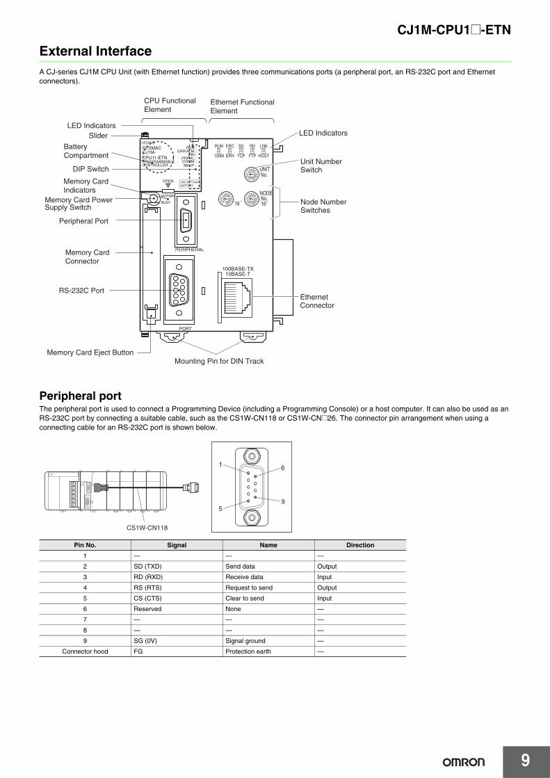
External InterfaceA CJ-series CJ1M CPU Unit (with Ethernet function) provides three communications ports (a peripheral port, an RS-232C port and Ethernet connectors).
Peripheral portThe peripheral port is used to connect a Programming Device (including a Programming Console) or a host computer. It can also be used as an RS-232C port by connecting a suitable cable, such as the CS1W-CN118 or CS1W-CN@26. The connector pin arrangement when using a connecting cable for an RS-232C port is shown below.
Pin No. Signal Name Direction
1 — — —
2 SD (TXD) Send data Output
3 RD (RXD) Receive data Input
4 RS (RTS) Request to send Output
5 CS (CTS) Clear to send Input
6 Reserved None —
7 — — —
8 — — —
9 SG (0V) Signal ground —
Connector hood FG Protection earth —
CONTROLLER
CJ1M-CPU11-ETN
SYSMAC
PROGRAMMABLE
ERR/ALMRUN
COMM
INHPRPHL
OPEN
PERIPHERAL
BUSY
MCPWR
PORT
´16 1
0123456789ABCDEF
0123456789ABCDEF
UNIT No.
RUN ERC SD RD
ERH TCP FTP HOST
100BASE-TX10BASE-T
0123456789ABCEF
NODE No.´16 0
100M
LNK
BKUP
SW SETTINGBATTERY
LED Indicators
BatteryCompartment
Memory Card Power Supply Switch
Memory Card Eject Button
Peripheral Port
DIP Switch
Memory CardIndicators
RS-232C Port
Mounting Pin for DIN Track
Unit Number Switch
Node Number Switches
EthernetConnector
Memory CardConnector
CPU Functional Element
Ethernet Functional Element
LED IndicatorsSlider
5
1
9
6
CS1W-CN118

10
CJ1M-CPU1@-ETN
RS-232C Port
Note: Baud rates for the RS-232C are specified only up to 19.2 kbps. The CJ-Series supports serial communications from 38.4 kbps to 115.2 kbps, but some computers cannot support these speeds. Lower the baud rate if necessary.
Note: Do not use the 5-V power from pin 6 of the RS-232C port for anything but the NT-AL001-E Link Adapter. Using this power supply for any other external device may damage the CPU Unit or the external device.
Ethernet ConnectorsThe following standards and specifications apply to the connectors for the Ethernet twisted-pair cable.• Electrical specifications: Conforming to IEEE802.3 standards.• Connector structure: RJ45 8-pin Modular Connector
(conforming to ISO 8877)
Item Specification
Communications method Half duplex
Synchronization Start-stop
Baud rate 0.3/0.6/1.2/2.4/4.8/9.6/19.2/38.4/57.6/115.2 kbps(See note.)
Transmission distance 15 m max.
Interface EIA RS-232C
Protocol Host Link, NT Link, 1:N, No-protocol, or Peripheral Bus
Pin No. Signal Name Direction
1 FG Protection earth —
2 SD (TXD) Send data Output
3 RD (RXD) Receive data Input
4 RS (RTS) Request to send Output
5 CS (CTS) Clear to send Input
6 5V Power supply —
7 DR (DSR) Data set ready Input
8 ER (DTR) Data terminal ready Output
9 SG (0V) Signal ground —
Connector hood FG Protection earth —
Pin No. Signal Name Direction
1 TD+ Transmission data + Output
2 TD- Transmission data - Output
3 RD+ Reception data + Input
4 — Not used. —
5 — Not used. —
6 RD- Reception data - Input
7 — Not used. —
8 — Not used. —
Hood FG Frame ground —
5
1
9
6

11
CJ1M-CPU1@-ETN
Demensions (Unit : mm)
CJ1M CPU Unit (with Ethernet function)CJ1M-CPU11-ETN/CPU12-ETN/CPU13-ETN
BKUP
SW SETTINGBATTERY
CONTROLLER
CJ1MCPU11-ETN
SYSMAC
PROGRAMMABLE
ERR/ALMRUN
COMM
INHPRPHL
OPEN
PERIPHERAL
BUSY
MCPWR
PORT
62
2.7
2.7
90
UNIT No.
100BASE-TX10BASE-T
NODE No.x160x16
1
0123456789ABCDEF
0123456789ABCDEF 012
3456789ABCDEF
RUN ERC SD RD
ERH TCP FTP HOST100M
LNK
6573.9

CJ1M-CPU1@-ETN
12
Related ManualsCat. No. Model Manual Application Description
W441 CJ1M-CPU1@-ETN
CJ-series CJ1M CPU Unit (with Ethernet function)Operation Manual
Information on CPU Units with Ethernet, including an overview, specifications, and maintenance
Describes the following for CJ1M CPU Units with Ethernet function• Overview and features• Basic system configurationAlso refer to the Operation Manual (W393) and Ethernet Units Operation Manual (W420 and W421)
W393
CJ1H-CPU@@H-RCJ1G-CPU@@CJ1M-CPU@@CJ1G-CPU@@PCJ1G/H-CPU@@H
SYSMAC CJ/NSJ Series Operation Manual
Basic specifications on CJ-series PLCs, including an overview, designing, installation, and maintenance
Describes the following for CJ-series CPU Units• Overview and features• System configuration• Mounting and setting procedure• Remedies for errorsAlso refer to the Programming Manual (W394)
W394
CS1G/H-CPU@@HCS1G/H-CPU@@-EV1CS1D-CPU@@HCS1D-CPU@@SCJ1H-CPU@@H-RCJ1G/H-CPU@@HCJ1G-CPU@@CJ1G-CPU@@PCJ1M-CPU@@NSJ@@-@@@@@-@@@
SYSMAC CS/CJ/NSJ Series Programming Manual
Information on all of the PLCs in the CS/CJ Series
This manual describes programming and other methods to use the functions of the CS/CJ-series and NSJ-series PLCs.
W474
CS1@-CPU@@@-@@CJ1@-CPU@@@-@@CJ2@-CPU@@-@@@NSJ@@-@@@@@-@@@
CS/CJ/NSJ-seriesInstructions Reference Manual
Information on instructions
Describes each programming instruction in detail.Also refer to the Software User’s Manual for the CPU Units when you do programming.
W342
CJ2H-CPU6@-EIPCJ2H-CPU6@CS1G/H-CPU@@HCS1G/H-CPU@@-V1CS1D-CPU@@HCS1D-CPU@@SCS1W-SCU@@-V1CS1W-SCB@@-V1CJ1H-CPU@@H-RCJ1G/H-CPU@@HCJ1G-CPU@@PCJ1M-CPU@@CJ1G-CPU@@CJ1W-SCU@@-V1CP1H-X@@@@-@CP1H-XA@@@@-@CP1H-Y@@@@-@CP1E-@@@@@-@NSJ@-@@@@@-@@@
CS/CJ/CP/NSJ-series Communications Command Reference Manual
Information on communications for CS/CJ/CP-series CPU Units and NSJ-series Controllers
Describes C-mode commands and FINS commands Refer to this manual for a detailed description of commands for communications with the CPU Unit using C mode commands or FINS commands.Note: This manual describes the communications commands
that are addressed to CPU Units. The communications path that is used is not relevant and can include any of the fol-lowing: serial ports on CPU Units, communications ports on SerialCommunications Units/Boards, and Communications Units. For communications commands addressed to Spe-cial I/O Units or CPU Bus Units, refer to the operation man-ual for the related Unit.
W341CQM1H-PRO01-ECQM1-PRO01-EC200H-PRO27-E
SYSMAC CS/CJ Series Programming Consoles Operation Manual
Programming Console operating procedure
Provides information on how to program and operate CS/CJ-series PLCs using a Programming Console.
W420 CS1W-ETN21CJ1W-ETN21
Ethernet Units Operation Manual Construction of Networks
Information when using an Ethernet Unit
Provides information on operating and installing 100Base-TX Ethernet Units, including details on basic settings and FINS communications.Refer to the Communications Commands Reference Manual (W342) for details on FINS commands that can be sent to CS-series and CJ-series CPU Units when using the FINS communications service.
W421 CS1W-ETN21CJ1W-ETN21
Ethernet Units Operation Manual Construction of Applications
Provides information on constructing host applications for 100Base-TX Ethernet Units, including functions for sending/receiving mail, socket service, automatic clock adjustment, FTP server functions, and FINS communications.
W446
WS02-CXPC@-V@
CX-Programmer Operation Manual Support Software for
Windows computersCX-Programmer operating procedure
Describes operating procedures for the CX-Programmer.Also refer to the Software User’s Manual (W473) and Instructions Reference Manual (W474) when you do programming.W447
CX-Programmer Operation Manual Functions Blocks
W464 CXONE-AL@@D-V@
CS/CJ/CP/NSJ-seriesCX-Integrator Network Configuration Software Operation Manual
Network setup and monitoring Describes the operating procedures for the CX-Integrator.
W463 CXONE-AL@@D-V@ CX-One Setup Manual Installing software from the CX-One
Provides an overview of the CX-One FA Integrated ToolPackage and describes the installation procedure.

Terms and Conditions Agreement Read and understand this catalog. Please read and understand this catalog before purchasing the products. Please consult your OMRON representative if you have any questions or comments. Warranties. (a) Exclusive Warranty. Omron’s exclusive warranty is that the Products will be free from defects in materials and workmanship for a period of twelve months from the date of sale by Omron (or such other period expressed in writing by Omron). Omron disclaims all other warranties, express or implied. (b) Limitations. OMRON MAKES NO WARRANTY OR REPRESENTATION, EXPRESS OR IMPLIED, ABOUT NON-INFRINGEMENT, MERCHANTABILITY OR FITNESS FOR A PARTICULAR PURPOSE OF THE PRODUCTS. BUYER ACKNOWLEDGES THAT IT ALONE HAS DETERMINED THAT THE PRODUCTS WILL SUITABLY MEET THE REQUIREMENTS OF THEIR INTENDED USE. Omron further disclaims all warranties and responsibility of any type for claims or expenses based on infringement by the Products or otherwise of any intellectual property right. (c) Buyer Remedy. Omron’s sole obligation hereunder shall be, at Omron’s election, to (i) replace (in the form originally shipped with Buyer responsible for labor charges for removal or replacement thereof) the non-complying Product, (ii) repair the non-complying Product, or (iii) repay or credit Buyer an amount equal to the purchase price of the non-complying Product; provided that in no event shall Omron be responsible for warranty, repair, indemnity or any other claims or expenses regarding the Products unless Omron’s analysis confirms that the Products were properly handled, stored, installed and maintained and not subject to contamination, abuse, misuse or inappropriate modification. Return of any Products by Buyer must be approved in writing by Omron before shipment. Omron Companies shall not be liable for the suitability or unsuitability or the results from the use of Products in combination with any electrical or electronic components, circuits, system assemblies or any other materials or substances or environments. Any advice, recommendations or information given orally or in writing, are not to be construed as an amendment or addition to the above warranty. See http://www.omron.com/global/ or contact your Omron representative for published information. Limitation on Liability; Etc. OMRON COMPANIES SHALL NOT BE LIABLE FOR SPECIAL, INDIRECT, INCIDENTAL, OR CONSEQUENTIAL DAMAGES, LOSS OF PROFITS OR PRODUCTION OR COMMERCIAL LOSS IN ANY WAY CONNECTED WITH THE PRODUCTS, WHETHER SUCH CLAIM IS BASED IN CONTRACT, WARRANTY, NEGLIGENCE OR STRICT LIABILITY. Further, in no event shall liability of Omron Companies exceed the individual price of the Product on which liability is asserted. Suitability of Use. Omron Companies shall not be responsible for conformity with any standards, codes or regulations which apply to the combination of the Product in the Buyer’s application or use of the Product. At Buyer’s request, Omron will provide applicable third party certification documents identifying ratings and limitations of use which apply to the Product. This information by itself is not sufficient for a complete determination of the suitability of the Product in combination with the end product, machine, system, or other application or use. Buyer shall be solely responsible for determining appropriateness of the particular Product with respect to Buyer’s application, product or system. Buyer shall take application responsibility in all cases. NEVER USE THE PRODUCT FOR AN APPLICATION INVOLVING SERIOUS RISK TO LIFE OR PROPERTY OR IN LARGE QUANTITIES WITHOUT ENSURING THAT THE SYSTEM AS A WHOLE HAS BEEN DESIGNED TO ADDRESS THE RISKS, AND THAT THE OMRON PRODUCT(S) IS PROPERLY RATED AND INSTALLED FOR THE INTENDED USE WITHIN THE OVERALL EQUIPMENT OR SYSTEM. Programmable Products. Omron Companies shall not be responsible for the user’s programming of a programmable Product, or any consequence thereof. Performance Data. Data presented in Omron Company websites, catalogs and other materials is provided as a guide for the user in determining suitability and does not constitute a warranty. It may represent the result of Omron’s test conditions, and the user must correlate it to actual application requirements. Actual performance is subject to the Omron’s Warranty and Limitations of Liability. Change in Specifications. Product specifications and accessories may be changed at any time based on improvements and other reasons. It is our practice to change part numbers when published ratings or features are changed, or when significant construction changes are made. However, some specifications of the Product may be changed without any notice. When in doubt, special part numbers may be assigned to fix or establish key specifications for your application. Please consult with your Omron’s representative at any time to confirm actual specifications of purchased Product. Errors and Omissions. Information presented by Omron Companies has been checked and is believed to be accurate; however, no responsibility is assumed for clerical, typographical or proofreading errors or omissions.
2016.4
In the interest of product improvement, specifications are subject to change without notice.
OMRON Corporation Industrial Automation Company http://www.ia.omron.com/
(c)Copyright OMRON Corporation 2016 All Right Reserved.