Synthetic Sling Failure Evaluations and Recommendations - …/67531/metadc934439/... · Synthetic...
45
RP P-RPT-42583 Revision 0 Synthetic Sling Failure - Evaluations and Recommendations Prepared for the U.S. Department of Energy Assistant Secretary for Environmental Management Contractor for the U.S. Department of Energy Office of River Protection under Contract DE-AC27-08RV14800 Approved for Public Release; Further Dissemination Unlimited
-
Upload
trinhthien -
Category
Documents
-
view
233 -
download
0
Transcript of Synthetic Sling Failure Evaluations and Recommendations - …/67531/metadc934439/... · Synthetic...
RPP-RPT-42583Revision 0
Synthetic Sling Failure Evaluations andRecommendations
Prepared for the U.S. Department of EnergyAssistant Secretary for Environmental ManagementContractor for the U.S. Department of EnergyOffice of River Protection under Contract DE-AC27-08RV14800
Approved for Public Release;Further Dissemination Unlimited

RPP-RPT-42583Revision 0
Synthetic Sling Failure - Evaluationsand Recommendations
C. S. HendersonT. C. MackeyWashington River Protection Solutions
Date Published
October 2009
Prepared for the U.S. Department of EnergyAssistant Secretary for Environmental Management
Contractor for the U.S. Department of EnergyOffice of River Protection under Contract DE-AC27-08RV14800
~. washington river~ protectionso/utionsP.O. Box 850Richland, Washington
Approved for Public Release;Further Dissemination Unlimited

TRADEMARK DISCLAIMERReference herein to any specific commercial product, process,or service by trade name, trademark, manufacturer, orotherwise, does not necessarily constitute or imply itsendorsement, recommendation, or favoring by the UnitedStates Government or any agency thereof or its contractors orsubcontractors.
This report has been reproduced from the best available copy.
Printed in the United Slales of America
RPP-RPT-42583Revision 0
RPP-RPT-42583, Rev. 0
EXECUTIVE SUMMARY
The information and evaluations provided in this report were compiled to address the recurringproblem of synthetic sling failure. As safety is the number one priority in all work aspects, asolution must be devised to prevent accidents from occurring. A total of thirteen cases regardingsynthetic sling failure were evaluated in order to determine their causes, effects, and preventativemeasures. From the collected data, it was found that all cases in which the synthetic slingcontacted the edge of its load resulted in sling failure.
It is required that adequate synthetic sling protection devices be used to protect slings in any liftwhere the sling comes in direct contact with the edge or comer of its load. However, there areno consensus codes or standards stating the type, material, or purpose of the type of protectivedevice used to protect the sling from being cut. Numerous industry standards and codes providevague descriptions on how to protect synthetic slings. Without a clear, concise statement of howto protect synthetic slings, it is common for inadequate materials and sling protection devices tobe used in an attempt to meet the intent of these requirements. The use of an inadequate slingprotection device is the main cause of synthetic sling failure in all researched cases.
Commercial sling protection devices come in many shapes and sizes, and have a variety ofnames, as well as advertised uses. "Abrasion pads" and ''wear protectors" are two differentnames for products with the same intended purpose. There is no distinguishable way todetermine the extent of sling protection which these devices will provide, or what specificscenarios they are made for. This creates room for error in a field where error is unacceptable.
This report provides a recommended action for hoisting and rigging activities which requiresynthetic slings to contact a load, as well as recommended changes to industry standards whichwill benefit overall industry safety.
1
RPP-RPT-42583, Rev. 0
TABLE OF CONTENTS
1.0 BACKGROUND 1
2.0 PURPOSE 1
3.0 INCIDENTS 1
4.0 METHOD OF ANALYSIS 3
5.0 SUMMARY OF RESULTS 4
6.0 CONCLUSION 4
7.0 RECOMMENDATIONS 5
8.0 REFERENCES 6
APPENDIX A - SLING FAILURE INCIDENTS AND ANALYSIS TABLE 7
APPENDIX B - NEW YORK CRANE ACCIDENT REPORT 10
APPENDIX C - INCIDENT DESCRIPTIONS AND LESSONS LEARNED 13
APPENDIX D - DOE OPERATING EXPERIENCE SUMMARY 22
APPENDIX E - DOE OPERATING EXPERIENCE SUMMARY 28
APPENDIX F - INCIDENT DESCRIPTIONS AND LESSONS LEARNED 31
APPENDIX G - NAVY CRANE CENTER TECHNICAL BULLETIN 34
APPENDIX H - INCIDENT DESCRIPTIONS AND LESSONS LEARNED 38
APPENDIX 1- SLINGMAX TECHNICAL BULLETIN AND DATA CHARTS .40
11

RPP-RPT-42583, Rev. 0
1.0 BACKGROUND
It is common rigging practice to use crane slings in both basket and choker configurations.These rigging options can be used for a variety of sling types including synthetic, wire mesh, orwire rope, which are all used on an ordinary basis. However, when the object to be liftedcontains an edge or comer, these configurations subject the sling to immense pressure at thepoints of contact between the edge and the sling. There have been numerous accidents whichhave occurred due to underestimating or overlooking this fact. Appendix A provides a table of12 researched cases. In multiple cases, a synthetic sling was used over an edge with a slingprotection device, and both the sling and protection failed.
Sling protection devices are available on the market, which are meant to protect both the slingand the load from being damaged. Almost all protection on the market is designed to prevent"scuffing" or "abrasion" due to friction. Protection comes in a variety ofnames including"softeners," "wear pads," and "abrasion protection." For clarity, these devices will be referred toas "sling protection devices."
2.0 PURPOSE
The purpose of this report is to provide information and a recommended action for any lift inwhich the sling comes in contact with the lifted load or an edge or comer. Failure of a sling andits protection device due to placement over an edge is a huge safety concern. One major pointwhich must be stressed is that abrasion resistance and cut resistance are not the same thing.ASME B30.9-2006, section 4.10Ad, states that "Slings in contact with edges, comers,protrusions, or abrasive surfaces shall be protected with a material of sufficient strength,thickness, and construction to prevent damage." Using an abrasion resistant protective device inan application where cut resistance is required would not meet the intent of this standard. If anabrasion resistant protective device is used for edge protection instead of a cut resistant device,there is a chance of both sling and protection failure.
3.0 INCIDENTS
The first incident studied occurred on March 15, 2008, and involved the collapse of a towercrane in Manhattan, New York (App. B). A company was hired to erect a tower crane on a highrise construction project. During a "jumping" process used to increase the height of the crane,the four slings which were being utilized to install the lateral support collar at the 18th floorabruptly snapped. The catastrophic accident resulted in seven fatalities and extensive damage tothe surrounding area. The contractor was accused ofnegligent rigging practices. He allegedlyused four slings to support the collar when the manufacturer recommended that eight slings beused. The four slings, which were tied around the edges of the crane tower, were not protectedwith any sort ofpadding which caused severe cuts to the slings. On top of this, one of the slings
1
RPP-RPT-42583, Rev. 0
had pre-existing damage to it and should not have been used. All three of these practicescontributed to the accident.
In 2003, there was a tragic report of a foreman killed during installation of a conveyor beltcounterweight (App. C). A crane was used to hoist 13,370 lbs. of steel plates which were to beused for the counterweight. The connecting rods failed to align with the holes in the supportframe. The foreman was making an attempt to line the rods up when the slings carrying the loadfailed. He was struck by the plates and killed. No sling protection device was used to protect theslings from the edges of the plates. The slings failed due to cutting at the point where theycontacted the edge of the plate.
On September 15, 2008, at the Hanford Solid Waste Facility, a waste cask was dropped about4 inches due to failure of the synthetic slings (App. D). No protective padding was used toprotect the slings from the edges of the cask. Luckily, there were no injuries, and the caskremained undamaged. Protective devices to protect the slings were not used because the lifteditem was wrapped in plastic. Sling contact with the lifted item was not considered a hazard. Thesling was cut by an edge of cask which was underneath the plastic.
In an incident at the National Renewable Energy Lab in February of2005, a metal frame holdinga forklift weighing 5,100 lbs. was dropped when the load shifted and an unprotected edge cut oneof the slings (App. E). Once again, no protection was used on the edges in contact with theslings during the lift.
On November 4,2008, a synthetic sling failure caused a 13,400 lb. steel plate to be droppedduring construction of new laboratories at PNNL. (Ref 14). The unsettling thing about this caseis that sling protection was used during the lift. Three of the pads were store bought. The fourthwas a section of old synthetic sling, which is a common practice in industry. Unfortunately,these protection devices were inadequate to protect the sling from being sliced in halfby theedges of the steel plate. In a follow up investigation of the incident, no specific criteria for thetype ofprotection to be used with synthetic slings was found in any of the researched industryguides, lifting manuals, or regulatory citations.
On June 8, 2009, an 8,700 lb. piece of equipment was dropped at the Idaho National Laboratory(App. G). The cause of failure was, once again, a cut sling. Commercial sling protection,constructed of reinforced rubber, was used in three difference places on each of the two syntheticslings used during the lift. These protective devices, like a majority ofprotective devices on themarket, were designed to prevent "scuffing" and "abrasion." They were completely useless inprotecting the sling from the edges of the load, and both the protection and sling were sliced intwo where they contacted the edge of the load.
In another similar case involving rubber "abrasive" protection, a girder was dropped duringinstallation of a double girder bridge crane in 2007 (App. H). The protective devices used weredesigned to protect the sling and load from "chafing," and once again the exact same outcomewas reached. The edges of the girder cut through both the sling and the rubber protectiondevices, and the load was dropped.
2

RPP-RPT-42583, Rev. 0
In 2001 at Brookhaven National Laboratory, a Large Hadron Collider magnet was dropped4.5 feet (App. E). Again, "anti-chafing" type protection was used when it was clear that anticutting protection was needed due to sharp edges. The inadequate sling protection devices failedalong the edge of the magnet, the sling was cut, and the load crashed to the ground.
In October of 2004, a 65,000 lb. crane trolley was dropped during its replacement, and fell 4 feet(App. I). There were five protective devices used during the lift, and it is suspected that at leastone was not placed correctly. The edge of the trolley support beam cut the sling and the trolleyfell. The cause of this accident was due either to improper inspection of the lift configurationbefore the lift was made, inadequate protection of the sling by the protective devices, or both.
In an incident at the Idaho Reactor Technology Complex, a 5,400 lb. concrete ring fell while itwas being unloaded from a truck (App. E). The synthetic slings used in the lift were arranged ina choker configuration, and old pieces of fire hose were used to protect them from the edges ofthe ring. The fire hose and slings were cut by the edges of the concrete ring, and the load wasdropped.
A 26,000 lb. piece of equipment was dropped at Rocky Flats in Colorado during a test lift(App. E). Gloves were used for protection, and a raised metal edge on the equipment made shortwork ofboth the gloves and sling. The sling was cut, and the equipment fell to the ground.
4.0 METHOD OF ANALYSIS
After performing research on various brands of commercial sling protection devices, it wasdiscovered that a majority of companies do not offer protection which is designed to be cutresistant. There are four major manufacturers of sling protective devices. Of these, only onecompany offers protection specifically designed to prevent the sling from being cut, along withtesting information and a maximum rated load for which the sling protection would work. Theother companies merely provided images oftheir products, and stated that they worked for wearand abrasion protection.
Many sling protection devices provided basically the same type of protection. The productoffers sew on and/or Velcro wrap around type protection made ofvarious materials which aredesigned to reduce and prevent damage to the sling incurred by "abrasion" and "general wear."The most common materials used in construction were typically nylon or leather. There was noguarantee on the effectiveness of protection against either abrasion or cutting. Most offered thesame warning: "Wear protection may not prevent cutting or other sling damage," and gave noinformation on the protection rating..
After speaking with engineering at multiple sling protection device manufacturers, it wasconcluded that the protection they sold was to be used to the maximum rating of the sling itself.Representatives from each company said that their protection was not rated, and the ultimateeffectiveness could vary depending upon the lifting application. This leaves room foruncertainty which is unacceptable when a failed lift could prove life threatening to the workersinvolved.
3

RPP-RPT-42583, Rev. 0
If using sling protection devices, ensure they are specifically designated to protect slings frombeing cut by the edges of a load. One company offers products are constructed using Dyneema®polyethylene fiber, a common material used in bullet proof armor, safety gloves, and cables andrope where strength and durability are crucial. This company gave test results for abrasion andcutting, as well as a maximum protection rating of 25,000 Ibs. per inch of sling width for theirComerMax cut protection products.
5.0 SUMMARY OF RESULTS
Failure to use protective padding, as was witnessed in several of the described cases, does notcomply with multiple regulations including ASME B30.9, 29 CFR 1910, and WAC 296-2429419. These codes/standards basically state the same requirement in regards to the use ofprotective padding during lifts: edges in contact with slings must be padded with material ofsufficient strength to protect the sling.
This requirement that "materials of sufficient strength be used" is too broad and creates a hugeproblem. There is no way to determine if the padding selected for use is of sufficient strength toprotect the sling unless some sort of information is provided, such as a sling protection loadrating. A high majority of sling protection device manufacturers on the market do not supplyinformation on the effectiveness of their products. Without this information, a blind decision isultimately being made in hopes that the chosen protection will not fail.
Another issue which must be addressed is the inconsistent naming of protective devices. Invarious reports and marketing ads, sling protection devices are given a variety of namesincluding wear pads, softeners, sling protectors, comer protectors, abrasion pads, chaffing gear,scuffpads, and wear sleeves. With such an assortment of names, it is impossible to select anappropriate cut resistant sling protection device.
There is no way to determine if an edge calls for the use of cut resistant sling protection device.Any edge has the potential of cutting a sling if the contact point between the edge and sling issubjected to enough pressure. The only circumstance which a synthetic sling would be safe frompotential cutting would be a case in which the load is completely smooth and circular.
6.0 CONCLUSION
There is no requirement that sling protection devices be rated, or built to any specifications. Inorder to improve industry safety, this must be change. Too many accidents have occurredbecause "abrasion resistant" protection devices were used in cases which required "cut resistant"protection devices. There is no way to distinguish how sharp an edge must be in order to call fora cut resistant protection device instead of abrasion resistant protection device. A requirementmust be made that all sling protection devices be cut resistant, and that a protection load ratingon this cut resistance must be supplied by the manufacturer. The use of random material should
4
RPP-RPT-42583, Rev. 0
be prohibited, and only approved cut resistant protection devices should be used in any liftingapplication. This will eliminate any confusion on the question of what type of protection shouldbe used in what scenario. If these measures are taken, safe and successful lifts can be made with100% certainty that a synthetic sling failure will not occur due to inadequate protection of thesling.
The industry must also conform to one general name when referencing sling protection devices.There are too many variable names which are used regularly and create confusion. "Chaffinggear," "softeners," "scuffpads," and "wear pads" could all have different meanings to differentpeople. A common industry name must be established in order to eliminate any potentialconfusion, so that everyone involved in a project or lift are on the same page.
The table provided (App. A) shows twelve fairly recent incidents involving sling failures. Sixout of twelve of these accidents occurred due to inadequate sling protection which led to paddingand sling failure. Three of the twelve accidents occurred because of failure to use slingprotection. This problem must be addressed, and appropriate measures must be taken to ensurethat slings stay protected from the possibility ofbeing cut by a load.
7.0 RECOMMENDATIONS
Safety should be the number one priority in any hoisting and rigging application, and adequatemeasures should be taken to ensure the highest level of safety in all aspects. A requirementneeds to be established to require the use ofonly approved cut resistant sling protection devicesin all lifting applications. Industry standards need to be established that require sling protectiondevices to be cut resistant. The manufacturers must supply a clear protection load rating withtheir protective devices so they may be used safely. With a protection rating, a rigger will knowexactly how heavy a load he can handle without slicing a sling. The sling protection should alsobe required to have a single, standard, unambiguous industry name in order to eliminate potentialconfusion when using sling protection devices.
Unless an alternate configuration may be used in which sling contact with the load or edge isavoided by the sling altogether, the recomm ended solution is to use cut protection, or any cutresistant sling protection device which specifies a sling protection load rating and is backed bytesting and data. These protection devices should be used in all applications where the slingcomes in contact with a load, unless the load is circular and has no edges. If these actions aretaken, a lift can be made in confidence that there will not be a failure due to inadequatelyprotected slings.
5
RPP-RPT-42583, Rev. 0
8.0 REFERENCES
1. ASME B30.9-2006, Slings
2. ASME B30.26-2004, Rigging Hardware
3. DOE-STD-1190-2007, Hoisting and Rigging Standard
4. DOE-RL-92-36, Hanford site Hoisting and Rigging Manual
5. 29 CFR 1910, Occupational Safety and Health Standards
6. WAC 296-24-29419, Safe Operating Practices
7. www.iandisling.com
8. www.lni.wa.gov
9. www.dsm.com
10. www.lift-all.com
11. www.lift-in.com
12. www.caldwellinc.com
13. www.msha.gov
14. Pacific Northwest National Laboratory. "Critique MinuteslNotes," Event Number: SCPNSO-PNNL-PNNLBOPER-2008-0024. ATS # 39419.1. 11/06/08. Phone: 1-888-3757665.
6

------~--_._- ------
RPP-RPT-42583, Rev. 0
APPENDIX A-SLING FAILURE INCIDENTS AND ANALYSIS TABLE
7
RPP-RPT-42583, Rev. 0
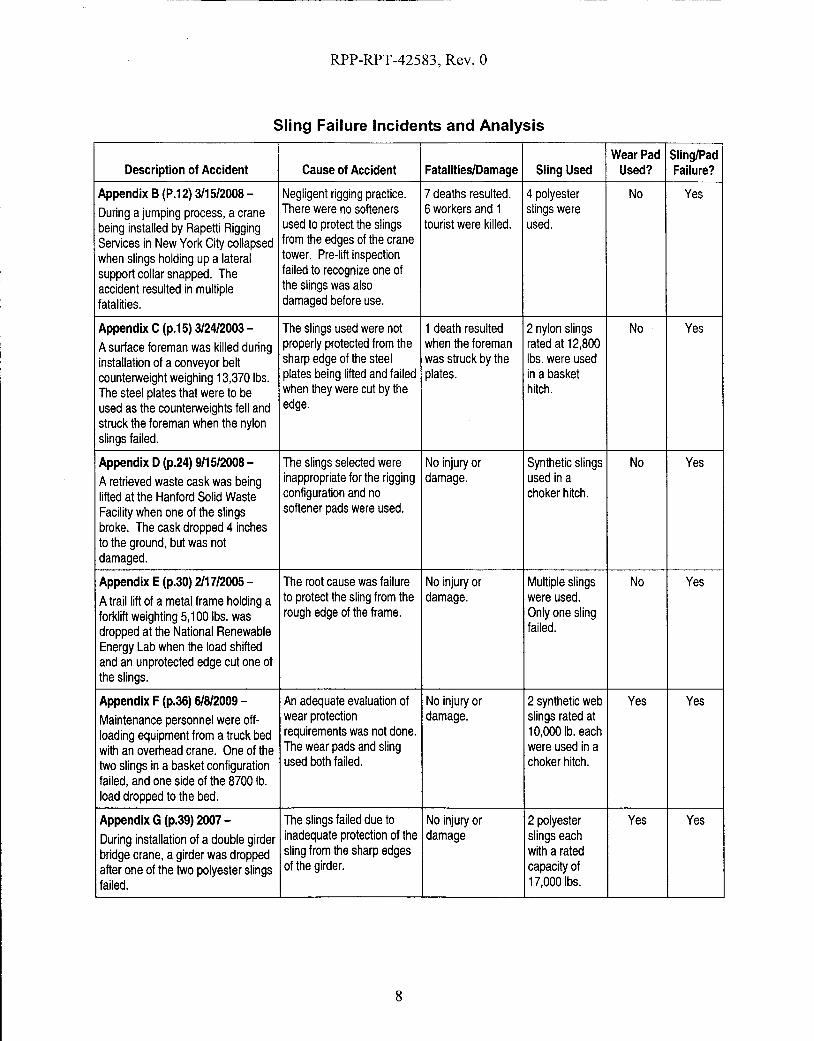
Sling Failure Incidents and Analysis
Wear Pad Sling/PadDescription of Accident Cause of Accident Fatalities/Damage Sling Used Used? Failure?
Appendix B(P.12) 3115/2008- Negligent rigging practice. 7deaths resulted. 4 polyester No YesDuring a jumping process, a crane There were no softeners 6 workers and 1 slings were
being installed by Rapetti Rigging used to protect the slings tourist were killed. used.
Services in New York City collapsed from the edges of the crane
when slings holding up a lateral tower. Pre-lift inspection
support collar snapped. The failed to recognize one of
accident resulted in multiple the slings was also
fatalities. damaged before use.
Appendix C(p.15) 3124/2003 - The slings used were not 1death resulted 2 nylon slings No Yes
Asurface foreman was killed during properly protected from the when the foreman rated at 12,800installation of aconveyor belt sharp edge of the steel was struck by the Ibs. were used
counterweight weighing 13,370 Ibs. plates being lifted and failed plates. in a basketThe steel plates that were to be when they were cut by the hitch.
used as the counterweights fell and edge.
struck the foreman when the nylonslings failed.
Appendix D(p.24) 9/15/2008- The slings selected were No injury or Synthetic slings No YesA retrieved waste cask was being inappropriate for the rigging damage. used in a
lifted at the Hanford Solid Waste configuration and no choker hitch.
Facility when one of the slings softener pads were used.
broke. The cask dropped 4 inchesto the ground, but was notdamaged.
Appendix E(p.30) 2117/2005 - The root cause was failure No injury or Multiple slings No YesAtrail lift of a metal frame holding a to protect the sling from the damage. were used.
forklift weighting 5,100 Ibs. was rough edge of the frame. Only one sling
dropped at the National Renewable failed.
Energy Lab when the load shiftedand an unprotected edge cut one ofthe slings.
Appendix F (p.36) 61812009 - An adequate evaluation of No injury or 2 synthetic web Yes YesMaintenance personnel were off- wear protection damage. slings rated at
loading equipment from a truck bed requirements was not done. 10,000 lb. each
with an overhead crane. One of the The wear pads and sling were used in atwo slings in a basket configuration used both failed. choker hitch.
failed, and one side of the 8700 lb.load dropped to the bed.
Appendix G(p.39) 2007 - The slings failed due to No injury or 2 polyester Yes Yes
During installation of adouble girder inadequate protection of the damage slings eachbridge crane, agirder was dropped sling from the sharp edges with a ratedafter one of the two polyester slings of the girder. capacity offailed. 17,000Ibs.
8

RPP-RPT-42583, Rev. 0
Sling Failure Incidents and Analysis
Wear Pad Sling/PadDescription of Accident Cause of Accident Fatalities/Damage Sling Used Used? Failure?
Appendix E(p.30) 8129/2001 - Inadequate protection was No injury or 2 synthetic Yes Yes
ALarge Hadron Collider magnet used to protect the slings damage. slings were
was dropped 4.5 feet at the from the sharp edges of the used. OnlyBrookhaven National Laboratory magnet. one was cut.
when one of the slings was cut.
Appendix H(p.42) 10/24/2004- Wear pads were improperly No injury. The 3 synthetic Yes Yes
During replacement of a 65,000 lb. installed and at least 1pad concrete floor was slings were
crane trolley, a synthetic sling failed was not in position to shattered and a used.
and one end of the trolley dropped protect the sling. The edge structural analysis
four feet to the floor. There were no of the trolley support beam was conducted.
injuries, but the concrete floor was cut the sling and the trolley
shattered. fell.
Appendix E(p.30) 7/11/2005- Asharp inner edge on the No injury or 2synthetic Yes Yes
A5,400 lb. concrete ring was ring cut through the padding damage. slings 20 feet in
dropped at the Idaho Reactor and one of the slings. This length were
Technology Complex while it was caused the second sling to used in a
being unloaded from a truck. also fail. choker hitch.
Appendix E(p.30) 8130/2002 - The weight of the No injury or No. info. Yes Yes
A26,000 lb. piece of equipment equipment was damage.
dropped 6 inches at Rocky Flats underestimated and the
when a test lift was being padding used to protect the
performed. sling from a raised metalridge was inadequate.
Appendix D(p.24) 9/24/2008 - The load was torque down Technician 2 synthetic N/A Yes
An overloaded synthetic sling failed during installation. The received minor slings each
at the Waste Isolation Pilot Plant operator accidently tried to injury from being rated at 3,200
and struck atechnician while trying lift the load instead of shipped by the Ibs.
to load an empty shipping cask onto lowering it which lifted the sling.
a trailer. load and the truck trailerand caused one of the twosynthetic slings to snap.
Appendix D(p.24) 8119/2008- Drawings/specification No injury or Eye bolts were N/A Yes
A6,000 lb. shield window liner fell 3 lacked the correct rigging damage. used along with
feet after two lifting eye nut configurations. Eye bolt a 3,000 lb.
assemblies sheared off from the top shoulder was not flush rated chain
of the liner due to side loading against the liner reducing hoist.
stresses. the overall strength.
9
RPP-RPT-42583, Rev. 0
APPENDIXB-NEW YORK CRANE ACCIDENT REPORT
District Attorney-New York District. News Release. January 5,2009.http://manhattanda.org/whatsnew/press/2009-01-05.shtml
10

RPP-RPT-42583, Rev. 0
New York County District Attorney's Office Robert M. Morgenthau, District Attorney
NEWS RELEASEJanuary 5, 2009
DISTRICT ADORNEY - NEW YORK COUNTY
Contact: Alicia Maxey Greene212-335-9400
Manhattan District Attorney Robert M. Morgenthau announced today the indictment of a tower cranerigger and his company on homicide and related charges in the crane collapse on March 15, 2008, thatcaused the deaths of seven people.
WILLIAM RAPEDI, 48, and RAPEDI RIGGING SERVICES INC. have been indicted on multiple charges ofmanslaughter, criminally negligent homicide, assault, reckless endangerment and failure to file tax returns.
The investigation leading to today's indictment revealed that RAPEDI, a tower crane rigger licensed by theNew York City Department of Buildings, and his rigging company, RAPEDI RIGGING SERVICES, were hired toerect the tower crane at a high-rise construction site at 303 East 51st Street in Manhattan. According to theNew York City Building Code, only licensed riggers are permitted to oversee this type of work and they mustbe present at the job site whenever erection and dismantling occurs.
On March 15, 2008, RAPEDI and a rigging crew working under his supervision installed several additionalsections to the mast of the tower to increase the height of the crane, in a process known as "jumping." Thecrew consisted of RAPEDI, who was directing operations from the 18th floor of the building, crane operatorWayne Bleidner, crane oiler Anthony Mazza, as well as Brad Cohen, Clifford Canzona, John Della Porta,Santino Gallone, and Aaron Stephens.
As part of the jumping process, the crew had to install a steel "collar" around the mast of the crane andconnect it to the 18th floor with steel tie-beams for lateral support. While the collar is being connected tothe tie-beams, it must temporarily be suspended from the crane mast with "slings" - polyester straps withloops at each end that attach to both the mast and the collar. However, during the collar and beaminstallation that day, the four slings being used abruptly snapped, causing the collar to slide down thetower. The collar, which weighed approximately 12,000 pounds, slid down the mast and crashed into collarat the 9th floor with sufficient force to dislodge it. The two collars then slid further down the mast andcrashed into the third floor collar, dislodging that one as well, leaving the crane completely unsupported.
The impact of the three collars violently jostled the base of the crane and caused the entire crane to tipover and collapse against the roof of an apartment building across the street on the south side of 51st
Street. The top of the crane, including the cab and boom, broke away from the lower sections andcatapulted over the apartment building and landed farther to the south, completely demolishing atownhouse on East 50th Street. Crane operator Bleidner and rigging crew members Canzona, Cohen,Gallone, Mazza, and Stephens died in the collapse. Odin Torres, an occupant of the townhouse demolishedin the collapse, was also killed. Crew member Della Porta was seriously injured, as were John Gallego andJuan Perez, two other occupants of the townhouse.
The investigation revealed that RAPEDI's reckless and negligent rigging practices caused the failure of theslings and the collapse of the crane. RAPEDI violated numerous provisions of the New York City BuildingCode, federal regulations, industry standards and the manufacturer's specifications pertaining to the properuse of the polyester slings. In particular, one of the failed slings had substantial pre-existing damage,including cuts and severe discoloration that would have been obvious to RAPEDI and he properly inspected
11
RPP-RPT-42583, Rev. 0
the sling as mandated by the Building Code, federal regulations, and industry standards. Because the preexisting damage had substantially diminished the capacity of that sling, it should not have been used at all.
In addition, all four slings had been tied to the crane in a knot called a "choke," which has the weakest loadbearing capacity of the three standard knots used in this type of operation. The slings were also tiedaround sharp metal edges of the crane tower without any kind of protective padding, which was also aviolation of the Building Code, federal regulations, industry standards and warning labels on the slingsthemselves. The use of the slings without protective padding caused severe cuts to the slings, greatlyreducing their capacity and ultimately leading to their failure. Finally, the investigation revealed thatRAPEDI failed to follow the crane manufacturer's specifications that the collar should have been supportedby eight slings, not four.
During the course of the investigation into the crane collapse, an examination of the financial records ofRAPEDI RIGGING SERVICES INC. revealed that the company did not file a corporate income tax return inNew York City for the tax years 2006 and 2007, in violation of the New York City Administrative Code.
RAPEDI and RAPEDI RIGGING SERVICES INC., are charged with seven counts of Manslaughter in theSecond Degree, a class C felony, which is punishable by up to 15 years in state prison, seven counts ofCriminally Negligent Homicide, a class Efelony, which is punishable by up to 4 years in prison; three countsof Assault in the Second Degree, a class D felony, which is punishable by up to 7 years in prison; one countof Reckless Endangerment in the Second Degree, a class A misdemeanor, which is punishable by up to oneyear in jail; and two counts of Failure to File a Return or Report, in violation of the New Your CityAdministrative Code, an unclassified misdemeanor, which is punishable by up to one year in jail and a fineup to $20,000.
The defendants are scheduled to be arraigned today in Part 1 of New York State Supreme Court.
Mr. Morgenthau thanked New York City Department of Investigation Commissioner Rose Gill Hearn,Assistant Commissioner John Kantor, Inspector General Michael Carroll and Assistant Inspector GeneralEdward Zinser, and Occupational Safety and Health Administration Manhattan Area Office Director RichardMendelson.
Assistant District Attorneys Sean Sullivan, Carey Ng and Deborah Hickey, all of whom are assigned to theRackets Bureau, are handling the prosecution of this case under the supervision of Eric Seidel, Chief of theRackets Bureau and Patrick J. Dugan, Chief of the Investigation Division. Investigators Jack Patterson andJonathan Savel also worked on the investigation, under the supervision of Investigation Bureau Chief JosephPennisI. Paralegals Michael Morris and Aaron Teitelbaum also assisted.
Defendents' Information:
WILLIAM RAPEDI, 9/6/1960129 Atlantic AvenueMassapequa Park, New York
RAPEDI RIGGING SERVICES, INC.129 Atlantic AvenueMassapaqua Park, New York
http://manhattanda.org/whatsnew/press/2009-01-05.shtml
12
6/22/2009

RPP-RPT-42583, Rev. 0
APPENDIXC-INCIDENT DESCRIPTIONS AND LESSONS LEARNED
United States Department of Labor, Mine Safety and Health Administration:Metal and Nonmetal Mine Safety and Health. "Report ofInvestigation:
Underground Nonmetal Mine (Limestone) Fatal Machinery Accident, March 24,2003."http://www.msha.gov/FATALSI2003/ft103m05.pdf
13

RPP-RPT-42583, Rev. 0
OVERVIEW
On March 24,2003, James G. Carey, surface foreman, age 46, was fatally injured when he wasstruck by a conveyor belt counterweight that was being installed. A crane was lifting steel platesthat were to be used as the counterweights. The victim was positioning the plates when therigging failed and the plates crushed him.
The accident occurred because the procedures used to install the counterweight were inadequate.When the connecting rod failed to align with the holes in the support frame cross-member, thevictim positioned himselfunder the suspended counterweight to drive the rod into position. Thenylon rigging straps, used to lift the steel counterweight, became damaged on the strap edges ofthe plates. The damaged rigging then failed and the counterweight fell.
GENERALINFO~ATION
JS&G Underground Mine #1, a limestone operation owned and operated by Joliet Sand & GravelCompany, was located in Joliet, Will County, Illinois. The principal operating officials wereGeorge Comerford, Jr., president; and Rob~rt Archibald, vice president. The mine was nonnallyoperated three, 8-hour shifts, six days a week. Total mine employment was 28 persons.
Limestone was mined underground using the room and pillar method. Headings were drilled,blasted, and loaded into haul trucks with front-end loaders. The trucks hauled the rock to theprimary crusher underground. The crushed rock was conveyed to surface via the declineconveyor belt and further processed at the mill, where it was sized, stockpiled and sold forconstruction aggregate.
The last regular inspection at this operation was completed February6, 2003. Another inspectionwas conducted following this investigation.
DESCRIPTION OF THE ACCIDENT
On the day of the accident, James G. Carey, surface foreman (victim), reported for work at7:00 am, his nonnal starting time. Michael H. Campbell, crane operator; Kevin Appleton,maintenance; and William Ferguson, maintenance; were the surface crew and Carey was theirsupervisor.
The surface crew went about normal maintenance duties until lunchtime, when they learned thata belt splicing crew had finished splicing the decline conveyor belt. After finishing their lunch,the surface crew traveled to the area of the decline conveyor belt take-up pulley to install a newcounterweight system.
The crew arrived at the decline conveyor take-up system and started assembling thecounterweight on top of two concrete blocks that were positioned directly under the take-up
14
RPP-RPT-42583, Rev. a
pulley. The counterweight consisted of 14 steel plates designed to be held together and attachedto the take-up pulley with three threaded steel rods.
Carey calculated the load and selected two nylon web straps to attach to the plates. The strapswere 12 feet long, 2 inches wide, and were rated for 12,800 pounds each in a basketconfiguration, which was used. Reportedly the straps were new and were removed from theirpackaging and Carey positioned them around the plates. The straps were then attached to chains,already in place, which in tum attached to steel cable slings hung from a crane. Carey thendirected Campbell to lift the load. After several attempts to line up the three bolts with theirrespective holes in the take-up pulley frame, Carey directed Campbell to lower the counterweighton the concrete blocks. Carey then repositioned the straps. One of the end bolts was removedand the other had dropped out. It was thought that it would be easier to thread the center bolt,attach the nut, then install the other two bolts. The crane operator was again directed to raise theweight.
As the counterweight plates were lifted into position, Appleton, who was working from a manliftbasket above the take-up pulley frame, was to install the nuts. When the hanger bolt would notgo through the frame, Carey moved underneath the counterweight and used a sledgehammer todrive the bolt through. During this activity, the nylon slings failed and the counterweight struckCarey.
Campbell, Ferguson, and Appleton ran to aid Carey and 911 was called. Emergency personnelarrived and, because of the massive head trauma, they called the county coroner who arrived andpronounced the victim dead at 5:29 p.m.
INVESTIGATION OF THE ACCIDENT
MSHA was notified ofthe accident at 6:05 p.m. on March 24,2003, by a telephone call fromDan Foltywienwicz, risk manager, to Steven Richetta, assistant district manager. Aninvestigation was started the next day. An order was issued pursuant to section 103(k) of themine act to ensure the safety of miners.
An MSHA accident investigation team conducted a physical inspection of the accident scene,interviewed employees, and reviewed conditions and work procedures relevant to the accident.MSHA conducted the investigation with the assistance of mine management and employees.
DISCUSSION
Decline Conveyor
Crushed limestone ofminus la-inch size was conveyed from the primary crusher underground tothe surface by a series of conveyor belts. Sequentially, the material left the crusher on a shortbelt that dumped onto the transfer conveyor belt. At the end of the transfer belt, the materialdumped onto a decline conveyor belt. The 1,100-foot-long decline conveyor belt transported the
15
RPP-RPT-42583, Rev. 0
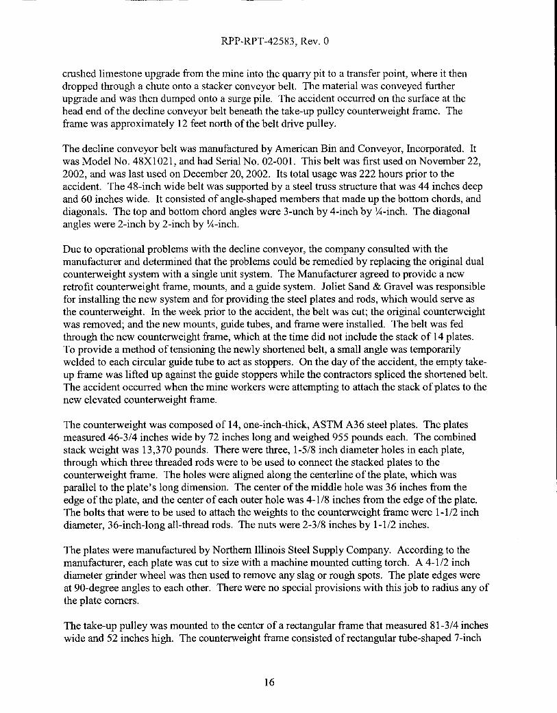
crushed limestone upgrade from the mine into the quarry pit to a transfer point, where it thendropped through a chute onto a stacker conveyor belt. The material was conveyed furtherupgrade and was then dumped onto a surge pile. The accident occurred on the surface at thehead end of the decline conveyor belt beneath the take-up pulley counterweight frame. Theframe was approximately 12 feet north of the belt drive pulley.
The decline conveyor belt was manufactured by American Bin and Conveyor, Incorporated. Itwas Model No. 48XI021, and had Serial No. 02-001. This belt was first used on November 22,2002, and was last used on December 20, 2002. Its total usage was 222 hours prior to theaccident. The 48-inch wide belt was supported by a steel truss structure that was 44 inches deepand 60 inches wide. It consisted of angle-shaped members that made up the bottom chords, anddiagonals. The top and bottom chord angles were 3-unch by 4-inch by y,j-inch. The diagonalangles were 2-inch by 2-inch by y,j-inch.
Due to operational problems with the decline conveyor, the company consulted with themanufacturer and determined that the problems could be remedied by replacing the original dualcounterweight system with a single unit system. The Manufacturer agreed to provide a newretrofit counterweight frame, mounts, and a guide system. Joliet Sand & Gravel was responsiblefor installing the new system and for providing the steel plates and rods, which would serve asthe counterweight. In the week prior to the accident, the belt was cut; the original counterweightwas removed; and the new mounts, guide tubes, and frame were installed. The belt was fedthrough the new counterweight frame, which at the time did not include the stack of 14 plates.To provide a method of tensioning the newly shortened belt, a small angle was temporarilywelded to each circular guide tube to act as stoppers. On the day of the accident, the empty takeup frame was lifted up against the guide stoppers while the contractors spliced the shortened belt.The accident occurred when the mine workers were attempting to attach the stack of plates to thenew elevated counterweight frame.
The counterweight was composed of 14, one-inch-thick, ASTM A36 steel plates. The platesmeasured 46-3/4 inches wide by 72 inches long and weighed 955 pounds each. The combinedstack weight was 13,370 pounds. There were three, 1-5/8 inch diameter holes in each plate,through which three threaded rods were to be used to connect the stacked plates to thecounterweight frame. The holes were aligned along the centerline of the plate, which wasparallel to the plate's long dimension. The center of the middle hole was 36 inches from theedge of the plate, and the center of each outer hole was 4-1/8 inches from the edge of the plate.The bolts that were to be used to attach the weights to the counterweight frame were 1-1/2 inchdiameter, 36-inch-long all-thread rods. The nuts were 2-3/8 inches by 1-1/2 inches.
The plates were manufactured by Northem Illinois Steel Supply Company. According to themanufacturer, each plate was cut to size with a machine mounted cutting torch. A 4-1/2 inchdiameter grinder wheel was then used to remove any slag or rough spots. The plate edges wereat 90-degree angles to each other. There were no special provisions with this job to radius any ofthe plate comers.
The take-up pulley was mounted to the center of a rectangular frame that measured 81-3/4 incheswide and 52 inches high. The counterweight frame consisted of rectangular tube-shaped 7-inch
16

RPP-RPT-42583, Rev. 0
by 5-inch by 3/8-inch top and bottom cross members and 5-inch by 5-inch by 3/8-inch verticalmembers, which fit over the 3-1/2-inch diameter circular slide tubes. The bottom cross memberwas predrilled with three holes for attaching the three threaded rods. Predrilled plates measuring8-inches by 5-inches by Y2-inch were welded at the three hole locations along the bottom crossmember.
Rigging
The bottom cross member of the counterweight frame was measured to be 96 inches from theground. Two concrete blocks, 2-feet by 2-feet by 6-feet were stacked between the counterweightguide tubes. The steel plates were then stacked one at a time on top of the 48-inch high blockplatform'prior to lifting them as a whole. Therefore, the 14-inch high stack ofplates needed tobe lifted approximately 34 inches in order to be bolted to the bottom cross member ofthecounterweight frame.
A P&H Model R-150 crane, Serial No. 33146, was used to lift the counterweight. It had anextending boom ranging in length from 24 feet to 60 feet and a maximum lifting capacity of 15tons. The crane was positioned along the west side of the conveyor with its outriggers fullyextended. The left front (northeast) outrigger was resting on two steel bearing plates to spreadthe load into a soft muddy area on the ground. For this lift, the crane's operating radius was 241/2 feet. According to the load chart posted on the crane, at this operating radius it had acapacity of 15,500 pounds. This capacity was limited by the stability of the crane againsttipping; not its structural competence. The crane was not equipped with a load indicating gauge.
Reportedly, the hoisting equipment consisted of a combination of wire ropes, chains, andsynthetic nylon slings. Starting from the tip ofthe crane boom, a four part line was connected tothe crane block. A 5-inch by 10-inch master link from a four-leg wire rope bridle was loopedover the crane hook. The four wire ropes were 5/8 inches in diameter and were 20 feet long.The hooks located at the end of each wire rope had a 10,000-pound working load limit. Two ofthe four wire ropes were strung down through the conveyor truss structure, while the other twowire ropes wrapped back up and were hooked onto the master link. With two wire ropes, therated capacity was approximately 14,000 pounds. Two metal chains were then draped over thewire rope end hooks that hung down through the conveyor truss structure. The chains hungdown around the take-up pulley, which was mounted to the counterweight frame. Each chain,which was made by ACCO, measured 16 feet long and had a 7,1 OO-pound working load limit. Ina basket lift configuration, similar to how it was draped over the wire rope hook, each chain hada capacity of 14,200 pounds. Finally, two nylon slings were wrapped around the counterweightplates in a basket configuration and attached to each chain hook.
Based on rub markings on the take-up pulley and on a diagonal (angle-shaped) brace in the topchord of the truss, it did not appear that it was a straight vertical pick up through thecounterweight frame and truss. In addition, the boom tip of the crane was positionedapproximately 1 foot to the west of the centerline ofthe conveyor belt. This off-center alignmentand interface may have caused a slightly unbalanced load to be applied to one of the nylonslings.
17
RPP-RPT-42583, Rev. 0
Accident Scene
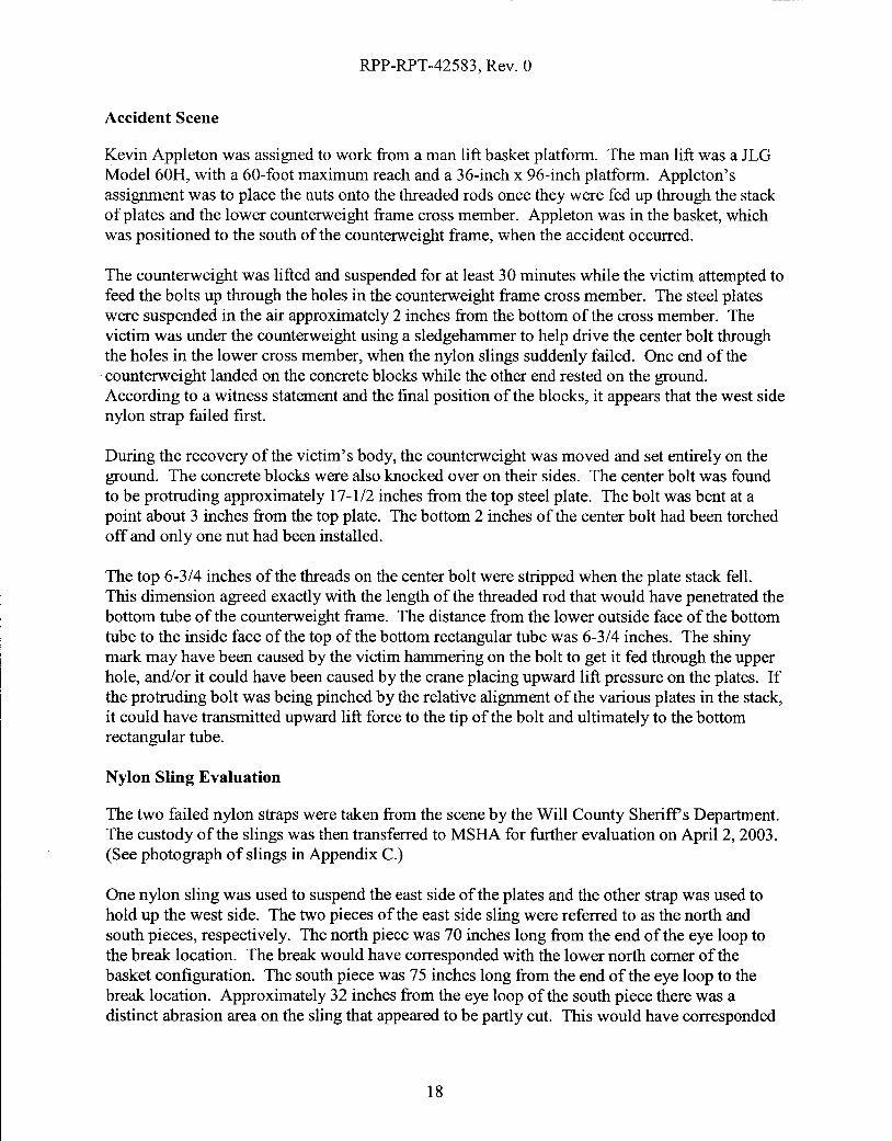
Kevin Appleton was assigned to work from a man lift basket platform. The man lift was a JLGModel60H, with a 60-foot maximum reach and a 36-inch x 96-inch platform. Appleton'sassignment was to place the nuts onto the threaded rods once they were fed up through the stackof plates and the lower counterweight frame cross member. Appleton was in the basket, whichwas positioned to the south of the counterweight frame, when the accident occurred.
The counterweight was lifted and suspended for at least 30 minutes while the victim attempted tofeed the bolts up through the holes in the counterweight frame cross member. The steel plateswere suspended in the air approximately 2 inches from the bottom ofthe cross member. Thevictim was under the counterweight using a sledgehammer to help drive the center bolt throughthe holes in the lower cross member, when the nylon slings suddenly failed. One end ofthe
.counterweight landed on the concrete blocks while the other end rested on the ground.According to a witness statement and the final position of the blocks, it appears that the west sidenylon strap failed first.
During the recovery ofthe victim's body, the counterweight was moved and set entirely on theground. The concrete blocks were also knocked over on their sides. The center bolt was foundto be protruding approximately 17-1/2 inches from the top steel plate. The bolt was bent at apoint about 3 inches from the top plate. The bottom 2 inches of the center bolt had been torchedoff and only one nut had been installed.
The top 6-3/4 inches ofthe threads on the center bolt were stripped when the plate stack fell.This dimension agreed exactly with the length of the threaded rod that would have penetrated thebottom tube of the counterweight frame. The distance from the lower outside face of the bottomtube to the inside face ofthe top of the bottom rectangular tube was 6-3/4 inches. The shinymark may have been caused by the victim hammering on the bolt to get it fed through the upperhole, and/or it could have been caused by the crane placing upward lift pressure on the plates. Ifthe protruding bolt was being pinched by the relative alignment of the various plates in the stack,it could have transmitted upward lift force to the tip of the bolt and ultimately to the bottomrectangular tube.
Nylon Sling Evaluation
The two failed nylon straps were taken from the scene by the Will County Sheriffs Department.The custody ofthe slings was then transferred to MSHA for further evaluation on April 2, 2003.(See photograph of slings in Appendix C.)
One nylon sling was used to suspend the east side of the plates and the other strap was used tohold up the west side. The two pieces of the east side sling were referred to as the north andsouth pieces, respectively. The north piece was 70 inches long from the end of the eye loop tothe break location. The break would have corresponded with the lower north comer of thebasket configuration. The south piece was 75 inches long from the end of the eye loop to thebreak location. Approximately 32 inches from the eye loop ofthe south piece there was adistinct abrasion area on the sling that appeared to be partly cut. This would have corresponded
18

RPP-RPT-42583, Rev. 0
to the south comer of the basket configuration. Likewise, evidence of yellow abraded nylonsling fibers was found adhering to the lower south edge of the east side of the stack ofplates.
The two pieces of the west side sling were also referred to as the north and south pieces,respectively. The north piece was 63-1/4 inches long from the end ofthe eye loop to the breaklocation. The break corresponded with the contact location of the lower north comer of thebasket configuration. The south piece was 82-112 inches long from the end of the eye loop to thebreak location. Approximately 40-1/2 inches from the eye loop on the south piece, there was adistinct abrasion area on the sling where it had started to be cut. This would have correspondedto the south comer of the basket configuration.
On April 23, 2003, an identical sling from the same manufacturer was tested at Safety Sling inPittsburgh, Pennsylvania. The tension load to break the sling was nearly 32,000 pounds. Thiswas at the expected factor of safety for a sling of this width. A direct pull test showed that afailure from tension overload is clearly different than the type ofrelatively abrupt tears thatoccurred when the slings were used around unprotected sharp plate comers on the day of theaccident. The failure surface of the tested sling had no distinct edge and had considerably morefraying than the accident slings.
Training and Experience
The victim had 8 years mining experience, all at this mine. He had received training inaccordance with 30 CFR, Part 48.
ROOT CAUSE ANALYSIS
Causal Factor - The nylon straps used to lift the steel plates were not protected from the sharpmetal edges of the steel.
Corrective Action - Always refer to manufacturer's recommendations, hazard alerts andwarnings. The nylon straps had labels stamped with warning to protect straps from sharp edgesand rough loads.
Causal Factor - The victim was working under a suspended load.
Corrective Action - Procedures should be established to ensure suspended loads are properlysupported prior to persons working under them. Management should review their safetyprogram and implement a job task analysis before maintenance work is performed.
Causal Factor - The conveyor belt was spliced together before the counterweight was installed.
Corrective Action - Review tasks that are performed infrequently to identify hazards that mayresult from work action sequence interruption. The counterweight installation should have beencompleted before the belt was spliced together. Design changes need to incorporate a safetyreview to insure such changes do not pose any unforeseen hazards. A job task analysis should be
19

RPP-RPT-42583, Rev. 0
developed to detect hazards and establish safe work procedures before performing maintenanceor repair work.
CONCLUSION
With respect to total load weight of 13,370 pounds, it does not appear that either the crane or therigging was used beyond their design capacity. However, the nylon slings wer~ not used inaccordance with the conditions indicated on the manufacturer's tag. The sharp edge comers ofthe counterweight plates cut through the west side sling first, instantly transferring the load to theeast side sling and the frictional interface between the threaded rod and the bottom tube of thecounterweight frame, neither of which could support the remaining load. The threaded rod bentand pulled out and the east side strap simultaneously broke, allowing the weights to fall on thevictim. The additional force caused by trying to lift the weight stack and feed its protruding boltthrough the hole may have contributed to the cutting of the slings.
A task analysis had not been conducted to identify possible hazards and establish safe proceduresto follow when installing the counterweight.
The difficulty posed by attempting to align and secure the counterweight ends was unexpectedand resulted in the victim positioning himself under the suspended load to drive the connectingrod into position. Failure to protect the nylon straps from damage caused by the edges ofthesteel plates contributed to the accident cause.
ENFORCEMENT ACTIONS
Order No. 6142021 was issued on March 25, 2003, under Section 103 (k) of the Mine Act:
A fatal accident occurred at this operation on March 24,2003, when a miner wasattempting to secure a hoisted gravity take-up pulley weight. This order is issued toassure the safety of persons at this operation and prohibits any work around the declineconveyor gravity take-up and P&H 15 ton crane, until MSHA determines that it is safe toresume normal operations as determined by an authorized representative of the Secretaryof Labor. The mine operator shall obtain approval from an authorized representative forall actions to recover and/or restore operations in the affected area.
This order was terminated on March 28,2003, after the conditions that contributed to theaccident no longer existed.
Citation No. 6155739 was issued on April 16,2003, under Section 104 (d)(I) of the Mine Act forviolation of30 CFR 57.16009:
A fatal accident occurred on March 24, 2003, at this operation when a supervisor wasstruck by a conveyor belt counterweight that was being installed. The victim waspositioned under the suspended counterweight using a hammer to guide a hanger bolt into
20

RPP-RPT-42583, Rev. 0
position when the nylon rigging straps failed. Failure to establish a procedure to installthe counterweight in a manner that would not require a miner to be positioned under thesuspended load to align the attachment bolts constitute more than ordinary negligenceand is an unwarrantable failure to comply with a mandatory standard.
This citation was terminated on June 26, 2003, after a mine operator devised a method to installthe counterweight that ensured persons would be clear of suspended loads. All personnel werere-instructed to stay clear of suspended loads.
Citation No. 6155740 was issued on April 16, 2003, under Section 104(a) ofthe Mine Act forviolation of30 CFR 57.16007b:
A fatal accident occurred on March 24,2003, at this operation when a supervisor wasstruck by a conveyor belt counterweight that was being installed. Nylon rigging strapshad been used to support the load, which consisted of 14 rectangular plates of steel thatweighed about 960 pounds each. The edges of the steel plates had sharp 90-degreeangles, which bore on the nylon straps, causing them to fail. These unprotected nylonslings were not suitable for this load with sharp edges. Labels on the slings warnedpersons to "Avoid sharp edges or rough loads" and to "Protect webbing from sharpedges".
The citation was terminated on June 26,2003, after the mine operator devis~d a method to installthe counterweight that ensured the use ofproper rigging. All personnel received rigging safetytraining on April 22, 2003 from a manufacturer of industrial rigging.
Approved by:
Felix A. QuintanaDistrict ManagerNorth Central District
Date:
21

RPP-RPT-425S3, Rev. 0
APPENDIXD-DOE OPERATING EXPERIENCE SUMMARY
DOE, Operating Experience Summary, Issue Number 200S-1 0, Article 1:"Three Recent Events Involved Failed Rigging and Lifting Hardware."
http://www.hss.energy.gov/csalanalysis/oesummary/oesummary200S/0ES 200S-10.pdf
22

NVJ
Three Recent Events InvolvedFailed Rigging and lifting Hardware
In i\ugust and Sept ember 2008. th ree events were reported10 ORT'S in which rigging (slings) and lifting hardware (eyebolls) failed. resulting in dropped luads. near misses, <Ind. inonl) lwent. minor injuries Lo a work or. I<;ach of th(~se ('vpntswas pnwent.ablp, anel all of tlwm could haVl~ had seriouseonsequenees.
On September ~4, ~008. at the Wasto Isolation Pilot ~llant.
an overloaded synthetic "ling failed (I<'igure 1·1) and struck awaste handling technicifln across the hflnd. forearm, and ('hest.The technicifln reeeiv(,d a minur injun' (redness of the skin)(ORPS Rppo/'I I·;~·!.CA FO··WTS·W! PP·211f1S·111112)
i\.ft(~r n~ll1ot.e handling personnel loadl-ld an empt.y shipping caskonto a trailer. an upper (rear) impact limiter was installed usingIwo slings and a ~:)·ton crane (Figure l·~). The aane operatorwas positioned on the northwest end of the trailer in clear viewof the operator spotting Ihe impacl Limiter into po"ition. Withthe impanlimiter in posit ion. two waste handling techniciflnsinst.alled bolt·s and torqued them, complet.ing installation ofthe limiter. The crane was maintaining approximately 2,i'i00pounds tension on the t.wo slings during the installation prucessRaeh synt hetie sling was rated at 8.200 pounds and hadsat israel ori I,v passe'lll a II prl),usl~ insp(~etions.
With the impact limiter installed, the workers positionedthemselves to lower the hoist so the rigging equipment eouldbe removed. When the spotter signaled Lhe crane operator tolower t.he hoist., t.he operator inadvcrl.ently moved the eont 1'01
stick t.o t.he hoist. (raise) position, instead of the position to lower
Figure 1·1. Worker holding failed synthetic sling
it, and rai~l~d the Imul higher. A Conlluct or Opprmions nwntorpositioned at the rear of the trai.l.lr notil:ed (hat both thl' caskilnd trail.:r werp bpginning to lift, but before he l:Ould cillI for astop. the slings broke and ~truck onl, of the tl~chn iciilllS. WorkWilS stopped and the scene was secured.
In it iaI investigation revea led that this event could have b(~en
attributed to inattent.ion 1.0 deLai I by the era ne operator,an improp()rly positioned load cell, or t.he lack or sufficientengineered barril~rs. The exuet causes will not Iw known untilthe Root Cause Analysis has b(~l,n l:Ompletl,d
On Sept('lmbl-~r Iii. 200R. at the I-Ianl()l'll Solid W,ISW F'<ll:ilit~·,
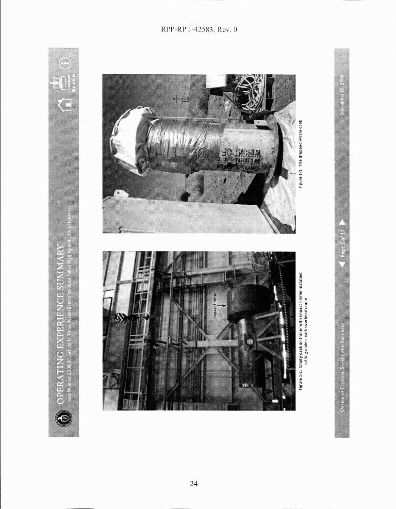
a !:ranI' WilS lilting a retrieved Wilstl~ eilsk when the slings used10 rig the cask to the erane broke. The waste cask d rappedapproximatel~.-4 inehes and landed in an upright position(I.'igure 1·;3). No one was injured. and the eask was notdamaged. (ORPS H,·pol·'. EM·Rf. .. f'lIM(;·SOI.lDWASTE·2110H.OIIOHj
;::0""0""0
?:J""0--l
I.j:::.NVl00'-.;J
;::0(1)
<o
'f tJ.:.
RPP-RPT-42583, Rev. 0
24

J"'~!'I~II.
~.~. ~?$i~1l1i
NVI
Investigators determined that the synthetic slings selected(Figure 1·4) were inappropriate for the rigging configuration,and softeners had not been used to cushion them. Bothconditions increased the potential for the slings to fail.
The load initiaUy was lifted approximately I foot to obtain theweight of the cask and was then lifted 3 feet for contaminationsurveys and removal of dirt. \~rhen the surveys were completed.the cask was raised approximately 4 feet to clear the racliolof,'icalcontrol barriel·. During these evolutions, personnel were within2 to 3leet of t.he cask. Fortunately, the sli ngs fniled when t.heyd.id; otherwise, personnel could have been seriously injured
Investigators determined that the riggers looked at the safeworking capacity of the sling'S in the basket con figuration(6,400 pou nds). not t.he choked configuration (2.400 pounds).However, they riggoed them in the choked configuration, with
Fle-ure 1-4. The cut sl1ne:
a total capacity of 4,800 pounds, even though the cask weighedapproximately 6.000 pounds. They cLid not make a secondcheck of t.he working capacity of the rigbring·. In adcLition. thesling'S were not protected by soft.eners at the flange interface,which created a sharp corner.
On Aug'ust 19,2008, fit the Hanford I ugh Levd Waste Par,ility,a 6.000-pound shield window liner toppleu3 feet to the gToundafter two lifting eye nut assemblies sheared ofI from the top ofthe window liner because of excessive side loading stJ·esses.Tron workers were at.tempting to lay the liner on its side whenthe J·jgging hardware failed (Figure 1-5). (ORPS Report EM-RP-
BNRP-RPPWTP-~008000J6;final report issued Sept.ember 30,2008)
The shield window liner had to be placed on its side to shortenthe logs and jacking bolts had to be added to help with its finalpositioning in a wall. The drop-forged, heavy-duty eye nuts
Fle:ure 1·5. WI ndow liner on Its side after eye nut stud failure
:::0'U'U
I
;;0""0>-J
I
+::NVI00GJ
;::::l(1)
<o

N0\
(l0,600-pound worklood rnting verticol pull) ond threaded studs(116.000 psi tensile strength) were installed according to themanufacturer's drawings and shipping instructions. The liftingeye nut wos threaded onto a metal stud that wos threoded into awelded flange on the liner.
The rig'ging for the eye nuts was positioned at opproximatelya 45-degTee angle, and the rigger was using a chain hoist toraise the legs off the ground when the shearing of the two studsoccurred. The riggers had successfully performed these sideloading lifts in the past on a similar sized window liner withno incident.
Invcstigotors learned that the drawings and specificationsprovided by Becht,el to the manufacturer lacked the correctrigging configurations and requirements. The drawings djdnot require the eye nut shoulder to be flush or seated with theHang'e of the shield window liner. The ch'awings left a o/s-inchexposcd neck (reveol) on the studs, reducing the overaLl strengthof the eye bolt osscmbly (Figure 1-6). Figure 1-7 shows one ofthe failed st.uds.
Investig'ators determined that there were no specificotions forshenr rating's fm· the studs and that a document review wouldhove identified the lack of lifting or rigging instructions andrestrictions. They olso determined that there were no materialhandling' directions for the window liners.
Investigators lenrned that the rigger used a chain hoist witha capacity of 3.000 pounds to lift the \vindow liner assembly,which weighed 6,000 pounds. The riggBr should hove used 0
chilln hoist \vith the capacity to motch the lift weight. After theconfig'uration of the stud bolts, the chain hoist became the nextwenkest link in the rigging' apparatus. The sling'S in use for t.hislift were not an issue.
Figure 1-6. Installed eye nut not shouldered to the flange
Figure 1-7. One of the four lifting flanges on the liner wlth a broken stud
?:''"0'"0
~'"0.....,I
.+::NVI00VJ
;;0(1)
-<o
Il;
•~
N--.l
The following guidance is from DOE·STD·1090-07, Hoistingund Rigg,:ng St,andcLrd (Form!?rly Hoisting and R,:ggingMannal).
Guidance for proper care and use of sling'S can be found inChapter 11, ,. Wire Rope and Slings." Section 11.3.1.4 of theStnnduru stutes thut overlouding shull be avnided, ns shallsudden dynamic loading that can buildup a momentaryoverload sufficient to bl'eak the sling. Section 11.3.5.i statesthat synthetic web slings can be cut by repeated use aroundsharp·cornered objects. The Standard identifies sever'altypes of protective devices that can be used to prevent slingdamage.
Chapter 12. "Rigging Hardware," provides requiTementsfor inspecting, testing, and using shackles, eyebolts, eyenuts, rings, wirc-rope clips, turnbuckles, rigging hooks, nndload-indicating devic.es used in hoisting and rigging'. Section12.5.1 of the Stnndnrd states that eye nuts shall only beused tor in·line loads.
These !?vents ltnderscore the importa.nce o( (allowing an apPl'Olicdli!t pla.n and ensuring that the rigging selection and Ii/linghru-dware are correctly and properly configu,red (01' the lift, ThePerson-in- Charge slwuld conduct a physical check of the load tolieri(y its configl.tral:ion a.nd placemenl- of rigging a.nd shol.tld (llsoensure that th!? load weight has been correctly calcula,ted.
KEYWORDS: Hoisting and rigging, sling, dropped load, near miss, eyebolt,eye nut
ISM CORE fUNCTIONS: Define the Scope of Work, Analyze the Hazards,
Develop and Implement Hazard Controls, Perform Work within Controls(0""0""0
~"'0--l
I+:0NVI00W
;;0(D
-<o
'II:

RPP-RPT-42583, Rev. 0
APPENDIXE-DOE OPERATING EXPERIENCE SUMMARY
DOE. Operating Experience Summary, Issue Number 2005-12, Article 1:"Sharp Edged Load Cuts Rigging Slings."
http://www.hss.energy.gov/csa/analysisloesummaryloesummary20051oes2005-12-screen.pdf
28
:f' fiI'
tv\,Q
Sharp-Edged LoadCuts Rigging SLings
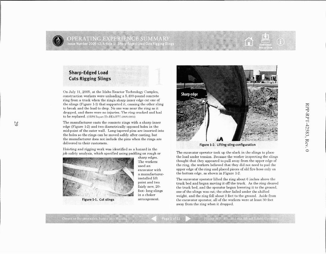
On July 11, 2005, at the Idaho Reactor Technology Complex,construction workers were unloading a 5,400-pound concretering from a truck when the ring's sharp inner edge cut one ofthe slings (Fig'ure 1-1) that supported it, causing the other slingto break and the load to drop. No one was near the ring as it(trapped, and there were no injuries. The ring cracked and hadto be replaced. (ORPS ReporllD--BEA-RTC-2005-0002)
The manufacturer casts the concrete rings with a sharp inneredge (Figure 1-2) and two diametrically opposed holes in themid-point of the outer wall. Long tapered pins are inserted intothe holes so the rings can be moved safely after casting, butthe manufacturer does not include the pins when the rings aredelivered to their customers.
Hoisting and rigging work was identified as a hazard in thejob safety analysis, which specified using padcling on roug'h or
sharp edges.The workersused anexcavator witha manufacturerinstalled liftpoint and twofairly new, 20foot- long slingsin a choker
Figure 1-1. Cut slings arra ngement.
FIgure 1-2. Lifting sling configuratIon
The excavator operator took up the slack in the sl ings to placethe load under tension. Because the worker inspecting the sling'Sthought that they appeared to pull away from the Lipper edg'e ofthe ring, the workers believed that they did not need to pad theupper edge of the ring and placed pieces of old fire hose only onthe bottom edge, as shown in Figure 1-2.
The excavator operator lifted the ring about 6 inches above thetruck bed and began moving it off the truck. As the ring clearedthe truck bed, and the operator began lowering it to the ground,one of the slings was cut; the other failed under the shiftedweight, and the ring fell about 3 feet to the ground. Aside fromthe excavator operator, all of the workers were at least 30 feetaway from the ring when it elI-opped.
;;0'i:I'i:I
~"'0....,I
.j::>.NVl00VJ
;;<:l(1)
<o
-.:

wo
Hoisting and rigging' work stopped so that the event could becritiqued. Work resumed after corrective actions (e.g., improvingwork planning and load inspection) were developed.
The OSHA Standard for Construction, 29 CFR 1926, containsrequirements for padding sling'S in section 2:; I(eW)): "Sling'Sshall be padded or protected from the sharp edg-es of theirloads." More specific guidance for using lining slin gs is found inthe DOE Standard I)()I·;'STI)- IODO-2001, Hoisting and Rigging(formerly Hoisting and Rigging Alanual). Chapter 11, "WireRope and Slings," describes how to protect slings from chafingor sharp edges using padding material such as corner saddles,burlap padding, wood blocks, and leather pads.
A search of ORPS yielded several other events caused by slingsthat failed on roug'h or sharp edges.
On February 17, 2005, at the National Renewable EnergyLaboratory, personnel were performing' a trial lift of a metalframe holding an extendable-boom forklift weig'hing about5,100 pounds when the load shifted une:o..'j)ectedly and anunprotected rough edge cut one of the slings. One side ofthe load dropped about 3 feet, but no injuries or damageresulted. The root cause was the rough edge that the workershad noticed, but neglected to protect against. (ORPS Report GO-·
NREL-NREL-2005-0002)
On August 30,2002, at Rocky Flats, as a subcontractor workgroup was performing a test lift of a 26,OOO·pound piece ofequipment, a raised metal ridge near the bottom of the basecut the slings, causing the piece to drop about 6 inches. Thequalified riggers who prepared the lift underestimated theweight of the piece and used leather work gloves to protectagainst the ridge, but the gloves proved to be inadequate.No one was injured, and there was no equipment orstructural damag·e. (ORPS RepOl·t RFO--I<HLL-NONPUOPS1.2002-0003;
OE Sununary 2002-20)
On August 29, 2001, at the Brookhaven NationalLaboratory, one end of a Large Hadron Collider magnetfell approximately 4\1, feet to a concrete 11001' when one oftwo slings was cut through because ofinadcquate chafingprotection against a sharp edg'c of the magnet. (ORPS Report
CH-BH-BNL-BNL·2001-0023; OE SWlUllary 2001-09)
These euents demonstrate the importance o/properly planningfor a lift. ShQ./p or rough edges should be padded or so/tenedeuen if they do not appear to be cutting into the sling. Riggersshould know the weight of the load and u.se padding materialsthat adeqlwtely protect slings from dr.unage.
KEYWORDS: Sling, rigging, near miss, sharp edge
ISM CORE FUNCTIONS: Identify the Hazards, Develop andImplement Hazard Controls
;;v
'"'"?:J>-0......,I
~tvVI00W
('j(0
<o
••tf~II!\:lr;.r..i.

RPP-RPT-42583, Rev. 0
APPENDIXF-INCIDENT DESCRIPTIONS AND LESSONS LEARNED
Battelle Energy Alliance, LLC. "Sling Failure During Hoisting and Rigging Activity."Lesson ID: INL-BEA-ID-2009-434. August 11,2009
31
RPP-RPT-42583, Rev. 0
Sling Failure During Hoisting and Rigging Activity
Priority Descriptor: Blue/ Information
Lesson ID: INL-BEA-ID-2009-434
Originator: Battelle Energy Alliance, LLC
Date: 8/6/2009
Lessons Learned Statement: Ensure wear protection padding used in Hoisting andRigging activities is selected based on the conditions of the lift. Not all types of wearprotection are appropriate in all applications. Use of the incorrect wear protection paddingresulted in synthetic sling failure.
Discussion: On June 8, 2009, Maintenance personnel were in the process of off-loadingequipment from a truck bed with an overhead crane. Maintenance personnel routinelyhandle this equipment successfully, and a standard rigging configuration has beendeveloped for this activity. However, this time the equipment was loaded on the truck bythe vendor, and it was placed upside down from the normal orientation. This preventedthe use of the standard rigging configuration. The alternate rigging arrangement consistedof two synthetic web slings, used in a choke type configuration. The slings were rated at10.000 pounds each in this configuration. Commercial wear protection pads constructed ofreinforced rubber approximately 6 inches by 11 inches, 1/8 inch thick were used in threedifferent places on each of the two slings (total of 6 pads). The wear protection pads werelocated in areas where the slings contacted the equipment being lifted. While initiallylifting the load, a pause was made at approximately 2 inches to check the wear protectionpositioning. While the check was being made, one ofthe synthetic slings failed (wassevered completely in two), and one side of the 8700 pound load dropped approximately2 inches back to the transportation trailer bed. The wear protection located at the point ofsling failure showed significant scuffing and had been cut completely through as well. Theother side of the load remained suspended with no apparent damage to the sling or wearprotection pads.
Analysis: Maintenance personnel routinely handle this equipment successfully, but whenthe equipment was loaded on the truck by the vendor, it was placed upside down from thenormal orientation. This prevented the use of the standard rigging configuration. Whilethe need to change the rigging configuration was recognized and the alternate riggingarrangement identified, an adequate evaluation of wear protection requirements was notdone. Upon investigation it was determined that the wear protection pads used weredesigned to prevent scuffing and abrasion, but were not adequate to prevent cutting of thesling.
32

RPP-RPT-42583. Rev. 0
ASME B30.9-2006, requires that edges in contact with slings be padded with materials ofsufficient strength to protect the sling. The edge need not be "razor" sharp to damage andcut the slings. Compression and tension, combined with a "moderate" edge and nonpositive sling to load engagement, i.e., the sling skipping across the load edge, can result insling damage. Therefore, it is important to protect slings from damaging load edges whichcontact the sling. It is also important to realize that wear protection devices will notperform equally well when subjected to abrasion or cutting. Abrasion protection materials,designs and technology should be different from those employed to provide protectionfrom the cutting.
Actions:
1. Ensure that hoisting and rigging personnel are trained in the selection and use ofwear protection devices.
2. When lift conditions change, ensure that wear protection devices are evaluated andthat wear protection devices are selected for the specific conditions of the lift.
Contact Name/Phone number: Layne T Wray/ 208-526-6995 / [email protected]
References: Occurrence Report NE-ID-BEA-SMC-2009-0005; ASME B30.9-2006;DOE-STD-1090
33
RPP-RPT-42583, Rev. a
APPENDIXG-NAVY CRANE CENTER TECHNICAL BULLETIN
NAVFAC. The Crane Comer: Navy Crane Center Technical Bulletin. 54th Edition, June 2007.https:llportal.navfac.navy.millportallpage/portalINAVFACINAVFAC WW PPINAVFAC NCC
PP/FILES/54EDWEB.PDF
34

RPP-RPT-42583, Rev. 0
THE CRANE CORNERNavy Crane Center Technical Bulletin
http://portal.navfac.navy.miUncc 54th Edition - June 2007Editor: (lST) 967-3816/DSN 387-38161m nfsh nee crane [email protected]
A WORD FROM TOPSIDESam Bevins
Thus far, in FY2007, Navy shore activities are showing a very positive trend in the reduction of craneaccidents. Through the first seven months of this fiscal year, crane accidents are down by almost 25 percentover the same time period last year. If our activities can continue this positive trend through the alwayschallenging summer months, we can have our best year yet for Navy lifting and handling safety.
One area of concern, however, is the percentage of accidents that involve the operation of mobile cranes. Wekeep a close watch on mobile crane accidents since they can have a greater potential for serious consequencesthan other types of cranes. Serious accidents, such as two blockings, contact with overhead power lines, andoverloads (with the resulting loss of stability) are a frequent threat with mobile crane operations. For FY04, 05,and 06, the percentages of accidents that involved mobile cranes consistently decreased from 39 to 33 to 28percent respectively. This year, this percentage has crept back to 37 percent. While our activities are reducingaccidents with other types of cranes, we are not seeing similar reductions in mobile crane accidents.
Some types of accidents are more common with mobile cranes than with other crane types. Wire rope damagewas reported on seven accidents. The wire rope may jump off a boom tip sheave or be damaged on the drumfrom mis-spooling due to improper operation. Two-blocking is an all too frequent occmrence, usually with noload on the hook as the crane is being set up for operation or shut down for transit at the end of the shift.Envirorunental conditions can have more of an effect on mobile cranes than other types of cranes. Wind andwave action were contributing factors in four of the accidents. Two common ship support lifts where mobilecrane accidents occur are brow lifts and shore power cable lifts. Five of the reported accidents occmred duringthese lifts.
Operational risk management is vital for every mobile crane operation Properly identifying and assessing allthe risks associated with the crane itself, the lift site, the load to be handled, the crane team, environmentalconditions, and other influencing factors can be a challenge.
Our video, Mobile Crane Safety, covers seven topics: laying a foundation for safety, teamwork, crane setup,understanding crane capacities, rigging considerations, safe operating procedures, and traveling and securingmobile cranes. The video is available at http://dodimagery.afis.osdmilJ(DAVIS/DITIS)(PIN806721).This isa worthwhile training aid to help ensure mobile crane lifts are properly planned and executed
Inside This IssueA Word From Topside. Page 1UFC 3-32Q-OlN, 'Neight Handling Equipment,Page 2Back-up Monitonng System, Page 2CSAs & EDMs. Page 3Second-Quarter FY07 Accident Report, Page 5NAVFAC P-307 Web Based Training. Page 7Crane Awareness torthe Summer Months, Page 72007 Weight Handling Improvement Conference.Page 8
Mobile crane safety is.critical to fleet readiness and to the personalsafety of everyone in the vicinity of a mobile crane operation. Takethe time to properly assess all the risks. Make the right riskdecisions. Let's have our best year yet for mobile crane safety.
35

RPP-RPT-42583, Rev. 0
of operational risk management (ORM) were not employed to mitigate the risks associated with possible windgusts on a day when the reported sustained wind conditions exceeded 15 mph.
Lessons Learned: Environmental factors (wind, rain, etc) must be considered prior to and during craneoperations. The operator and personnel performing rigging functions are responsible to ensure the load is safeto lift, properly secured, and properly controlled. Ifthere is doubt, stop the operation until conditions improveor request assistance.
PERSONAL INJURY
Accident: During removal of a brow, a rigger was struck in the head by a hinged walk ramp. A crane teamwas assigned to remove a brow and shore power cables from a ship that was preparing to get underway. Timeconstraints increased the operational tempo of the crane team. After successfully removing the shore powercables, the crane team used a four point pick to lift the brow. The brow had a hinged walk ramp on one end.An individual on the ships deck raised the walk ramp and held it until the brow was raised and rotated awayfrom the ship. As the brow was lowered to the ground, the walk ramp opened and struck one of the riggers inthe head. The ramp was not secured to the brow to prevent movement and the crane team did not check thecondition of the ramp prior to lifting the brow. Tag lines were not used. The injured rigger was standing inclose proximity to the suspended load. Personal protective equipment (hard hat) was worn and it likelyprevented serious injury.
Lessons Learned: Rigging personnel must make sure all latches, ramps, and other attachments are securedbefore the crane moves any equipment. Crane team personnel should avoid placing themselv~s in unsafepositions near suspended loads. The use of taglines reduces the need to be near a suspended load. Wearing ofpersonal protective equipment is an effective tool in reducing the potential for serious injury. Crane teamsupervision must ensure that work tempo does not degrade operational safety.
TWO-BLOCKINGS
Accident: During the operation of a category 4 truck mounted boom crane, it was two-blocked. The crane waspositioned with the boom to the rear and over the truck bed. The hook block was in the OEM designed stowedtravel position which deactivated the anti-two block function. In order to make a lift, the operator had toreposition the boom over the front of the truck. The operator raised the boom approximately 30 degrees andthen rotated the boom 180 degrees. During the movement, the operator two-blocked the crane. The subsequentinvestigation determined that the operator inadvertently operated the extend boom control when he intended tooperate the hoist down control. The force applied by the extension of the boom, damaged the wire rope. Thequalified operator had not operated the equipment for some time and failed to reacquaint himself with thecontrols or operational characteristics prior to starting the work or prior to any form of an operational check.
Lessons Learned: Trained operators must reacquaint themselves with the controls or operationalcharacteristics of the equipment, especially. After periods of non-operation. For mobile cranes that do notprovide protection against two blocking or when anti-two block functions are bypassed to stow or travel,activities must develop crane specific procedures to minimize the possibility of two-blocking.
SIGNIFICANT CONTRACTOR ACCIDENT
Accident: During the installation of a new double girder bridge crane, a girder was dropped after a rigging gearfailure. Several contractor employees sustained serious injuries. A contractor was utilizing a mobile hydrauliccrane to set the girder in place. The 22.5k pound girder was rigged with two 20 ft polyester round slings, eachwith a rated capacity of 17k pounds. After the girder had been suspended in a static position for approximately10 minutes, one of the two slings failed. The other sling likely failed due to overload. Both slings were
6
36

RPP-RPT-42583, Rev. 0
believed to have been protected by mbber matting that was used as chafing material. Based on the breaklocation and the condition of the chafing material, the most probable cause of the sling failure was due toinadequate protection ofthe sling from the sharp edges ofthe girder.
Lessons Learned: Synthetic slings can be easily cut at sharp corners or edges. Adequate chafmg protection isrequired for synthetic slings where there is a possibility ofthe sling being cut or otherwise damaged by the load.In the accidents noted above, the protection was inadequate. Chafing material must be of sufficient thicknessand strength to prevent sling damage. Synthetic rope slings and alternate yarn synthetic round slings require aspecific radius of curvature around sharp cornered objects (see NAVFAC P-307, section 14). This requirementalso applies to the minimum radius of curvature at corners of objects being lifted. With high stresses on theslings, soft chafing material may not maintain the minimum required radius or provide the required protection.Harder materials, such as split piping sections or special rounded shoes, are recommended. Sling manufacturersalso provide wear protection products that protect slings from sharp corners or edges. Also, ensure the riggingconfiguration is stable and slings cannot slide off the chafmg protection. In addition, ensure synthetic slings arenot excessively bunched in the bowl ofthe hook or in shackles. This can cause uneven loading on the syntheticfibers and failure of the sling. Finally, synthetic slings must be properly cared for and stored. Navy cranecenter auditors find more synthetic slings in poor condition than any of the other types of slings.
Weight handling program managers and safety officials are encouraged to review the above lessons learnedwith personnel performing lifting and handling functions and consider the potential risk of accidents occurringat your activity. OPNAVINST 3500.39B prescribes methods for assessing hazardous operations which shouldbe used in the planning and preparations of all WHE lifts.
E-mail submission of reports of accidents, unplanned occurrences and near misses is encouraged. The e-mailaddress is [email protected]. The reports must include a complete and concise situation description,corrective and preventive actions, probable cause and contributing factors, and an assessment of damage. Forequipment malfunction or failure, include siCifiC description of the component and the resulting effect orproblem caused by the malfunction or failure
NAVFAC P-307 Web Based Training
Two courses have been added to Navy Crane Center's growing list of web-based training courses: CraneRigger and Rigging Gear Inspection. This brings the total number of web-based training courses to five, whichalso includes: General Crane Safety Refresher, Category 2 Crane Safety Refresher, and Category 3 CraneSafety. Four more courses [General Crane Safety, Category 2 Crane Safety, Category 4 Crane Safety, and LoadTest Director] are scheduled to be converted to web-based format and made available online during the nextseveral months. Maintenance courses will be converted over the next 1-2 years. Web-based courses areavailable online through eLearning on Navy Knowledge Online (https:/lwww.nko.navy.mil). Traininginformation including course summaries, schedules, billeting, and online information can be viewed on NavyCrane Center's web site at https://portal.navfac.navv.millncc (click on training).•
CRANE AWARENESS FOR THE SUMMER MONTHS
As we approach the summer months, I again ask weight handling managers and supervisors to place a specialfocus on safe crane and rigging operations. Overall, the navy shore based crane accident statistics have beentrending downward as compared to last year and we have an opportunity to make FY07 the safest year onrecord. However, the summer months bring us a real challenge to maintain this downward trend. With theadded distractions associated with the warmer weather, maintaining a sharp focus on the critical job at handduring weight handling operations will be challenging. Surveillance of lifting and handling operations byexperienced personnel has proven to be an effective tool in accident prevention. During surveillances, look for
7
37
RPP-RPT-42583, Rev. 0
APPENDIXH-INCIDENT DESCRIPTIONS AND LESSONS LEARNED
Nuclear Regulatory Commission. "Browns Ferry Nuclear Plant-NRC Integrated Inspection Report." January 2005.
http://www.nrc.govINRR/OVERSIGHT/ASSESS/REPORTSlbf 2004005.pdf
38

RPP-RPT-42583, Rev. 0
b. Findings
Introduction: A Green self-revealing NCV was identified for the Failure to Comply with10 CFR 50 Appendix B, Criterion V, Instructions, Procedures and Drawings. As a resultof an inadequate procedure and poor human performance, a Reactor Building cranetrolley drop occurred.
Description: On October 24, licensee and contract personnel were conducting workusing we 04-716728-000, the implementing work document, for Design Change Notice(DCN) 60600 to upgrade the common Reactor Building 125-ton bridge crane. Part ofthe DCN was to replace the 65000-pound trolley with a new one. During the riggingprocess to remove and lower the old trolley from the overhead to the Unit 1 refuelingfloor, one synthetic sling failed and one end of the trolley dropped apprOXimately fourfeet to the concrete floor. The force associated with the drop resulted in the failure ofone of the two remaining slings on the other end of the trolley. Operations andengineering personnel immediately performed a series of detailed inspections anddetermined that no plant operability or safety issue resulted. The licensee determinedthat the event did not challenge the safe operation of Units 2 and 3 or cause entry intoany Limiting Conditions of Operation. The drop resulted in surface cracking and spallingof the concrete ceiling beneath the point of impact on the Unit 1 refueling floor. Thelicensee assembled a root cause investigation team to review the event and determineits root cause. The licensee also commissioned the services of an independentstructural engineer to analyze the structural integrity of the floor at the point of impact todetermine if the floor still met its design criteria.
The inspectors completed a walkdown of the affected areas, accompanied by a civilengineer from the licensee's staff, to view the craCked and spalled concrete from theceiling below the point of impact. The inspectors also toured the plant and the maincontrol rooms to assess the condition and status of safety-related systems. Theinspedors discussed the issue with licensee management, engineering, and operationspersonnel to assess immediate actions taken and gain an understanding of the detailedinspections completed by licensee personnel. The inspectors also assessedcompliance with the reporting requirements of NUREG-1022, Event ReportingGuidelines.
The inspectors later reviewed the licensee's root cause determination report to assessdetails, accuracy, and short and long term corrective actions. The inspectors noted thatthe root cause report was thorough, detailed, and comprehensive. The planned andcompleted actions were appropriate and comprehensive. The licensee identified severalroot and contributing causes. Root causes included i.nadequate work practices by thecontractor support personnel, and improper installation and verification of the rigging inthat the synthetic slings used in the Iifhvere not adequately protected.
The inspectors compared the root and contributing causes with information obtainedfrom the review of licensee work control documents, procedures, briefing papers listedin the attachment, and discussions with licensee personnel. The procedure to remove
Enclosure
39

RPP-RPT-42583, Rev. 0
the old trolley and install the new trolley was revised several times prior to itsimplementation. However, the rigging crew was not made aware of the final revisionand did not implement all of the requirements to use "softeners" to protect the slings andthat a line of sight be maintained to ensure that their effectiveness was maximized.
A single sling was rigged around the trolley support beam with five protective softeners.The softeners were verified at the beginning of the move but not during the move, asspecified by the rigging permit. Photographs showed that at least one softener at thetrolley beam was not in a position to protect the sling after the load was applied. As theold trolley was lowered close to the newtrolley, which was staged in preparation for itsinstallation, workers were concerned about possible interference between them. Thecontract project lead engineer determined that there would be additional clearance ifone end of the old trolley was lowered. There was no discussion or intervention by theTVA task manager, supervisor, or safety observer, even though at the pre-job briefing itwas emphasized that the load was to be maintained level. The trolley descent had beenhalted several times to level the load. \Nhen one end of the trolley was lowered, theedge of the trolley beam cut the single rigging sling and the trolley fell. Almostimmediately, one of the slings on the other end of the trolley failed and the trolley fell tothe refuel floor.
Analysis: The inspectors determined that the licensee's inadequate procedure and poorwork performance which resulted in the Reactor Building crane trolley drop thatoccurred on October 24, 2004, constituted a performance deficiency and a finding.This finding is greater than minor because it is associated with program and processattributes and affected the objective of the Initiating Event Cornerstone to limit thelikelihood of those events that upset plant stability and challenge critical safety functionsduring at-power operations. In addition, if left uncorrected, this finding would result in amore significant safety concern because structural damage to the refuel floor as well aspotential damage to the spent fuel pool would occur if the load had dropped from ahigher elevation. This finding did not represent an immediate safety concern. Thisfinding was evaluated using the SOP and was determined to be a finding of very lowsafety significance because no initiating event or transient actually occurred, there wasno permanent structural damage to the refuel floor, there was no functional degradation,and mitigating capability was not affected. The inspectors also determined that thecause of this finding was related to the human performance cross-eutting area.
Enforcement: 10 CFR SO Appendix B, Criterion V, states, in part, that activities affectingquality shall be prescribed by documented instructions, procedures, or drawings of atype appropriate to the circumstances and shall be accomplished in accordance withthese instructions, procedures, or drawings. Contrary to the above, inadequateprocedures (not using the latest approved revision to the procedure) and poor humanperformance resulted in the drop of the Reactor Building crane on October 24,2004.Because this failure to comply with 10 CFR SO, Appendix B, Criterion V, is of very lowsafety significance and has been entered into the 6censee's corrective action program,as PER 70752, this violation is being treated as an NCV, consistent with Section VI.A ofthe NRC Enforcement Policy: NCV 05000260, 29612004005-02, Inadequate Procedureand Poor Human Performance Resulted in a Drop of the Reactor Building Crane Trolley.
Enclosure
40