Revitalizing heritage and regions through branding Dr. J. Eshuis Erasmus University Rotterdam.

Synthesizing data-centric models from business processmodelsEshuis, H.; Van Gorp, P.M.E.
Published in:Computing
DOI:10.1007/s00607-015-0442-0
Published: 01/01/2016
Document VersionPublisher’s PDF, also known as Version of Record (includes final page, issue and volume numbers)
Please check the document version of this publication:
• A submitted manuscript is the author's version of the article upon submission and before peer-review. There can be important differencesbetween the submitted version and the official published version of record. People interested in the research are advised to contact theauthor for the final version of the publication, or visit the DOI to the publisher's website.• The final author version and the galley proof are versions of the publication after peer review.• The final published version features the final layout of the paper including the volume, issue and page numbers.
Link to publication
Citation for published version (APA):Eshuis, H., & Van Gorp, P. M. E. (2016). Synthesizing data-centric models from business process models.Computing, 98(4), 345-373. DOI: 10.1007/s00607-015-0442-0
General rightsCopyright and moral rights for the publications made accessible in the public portal are retained by the authors and/or other copyright ownersand it is a condition of accessing publications that users recognise and abide by the legal requirements associated with these rights.
• Users may download and print one copy of any publication from the public portal for the purpose of private study or research. • You may not further distribute the material or use it for any profit-making activity or commercial gain • You may freely distribute the URL identifying the publication in the public portal ?
Take down policyIf you believe that this document breaches copyright please contact us providing details, and we will remove access to the work immediatelyand investigate your claim.
Download date: 11. Jun. 2018

Computing (2016) 98:345–373DOI 10.1007/s00607-015-0442-0
Synthesizing data-centric models from business processmodels
Rik Eshuis · Pieter Van Gorp
Received: 11 January 2014 / Accepted: 19 January 2015 / Published online: 14 February 2015© The Author(s) 2015. This article is published with open access at Springerlink.com
Abstract Data-centric business process models couple data and control flow to spec-ifyflexible business processes.However, it canbedifficult to predict the actual behaviorof a data-centric model, since the global process is typically distributed over severaldata elements and possibly specified in a declarative way. We therefore envision adata-centric process modeling approach in which the default behavior of the processis first specified in a classical, imperative process notation, which is then transformedto a declarative, data-centric process model that can be further refined into a completemodel. To support this vision, we define a semi-automated approach to synthesize anobject-centric design from a business process model that specifies the flow of multiplestateful objects between activities. The object-centric design specifies in an imperativeway the life cycles of the objects and the object interactions. Next, we define a map-ping from an object-centric design to a declarative Guard-Stage-Milestone schema,which can be refined into a complete specification of a data-centric BPM system. Thesynthesis approach has been implemented and tested using a graph transformationtool.
Keywords Data-centric BPM · UML · Case management · Model transformation
Mathematics Subject Classification 68U01 · 68U31
R. Eshuis (B) · P. Van GorpEindhoven University of Technology, P.O. Box 513, 5600 MB Eindhoven, The Netherlandse-mail: [email protected]
P. Van Gorpe-mail: [email protected]
123

346 R. Eshuis, P. Van Gorp
1 Introduction
The classic way to model business processes is to specify atomic activities and theirordering in a flowchart-like, imperative process model. In recent years, data-centricmodeling paradigms have increasingly grown popular in research and industry as alter-native to the classic, activity-centric paradigm. Data-centric modeling approaches aimto have amore integrated perspective on business processes by treating data elements asfirst-class citizens next to process elements [22,29]. Moreover, data-centric modelingapproaches support the specification and execution of semi-structured, knowledge-intensive business processes [40], which are more difficult to support using classicprocess modeling.
These two paradigms are often positioned as alternatives, each having their ownmodeling techniques and implementation technologies. Data-centric approaches usefor instance statemachines [21,22,29,46] or business rules [7] asmodeling techniques,while activity-centric approaches use process flow models such as UML activity dia-grams [41] or BPMN [30], where each modeling technique is supported by dedicatedengines.
In this paper, we aim to combine the strengths of both approaches. An activity-centric model shows clearly the behavior of the process, while in a data-centric modelthe actual behavior is difficult to predict, either since the global process is distributedover different data elements or since the behavior is specified in a declarative way,for instance in the Guard-Stage-Milestone (GSM) approach [7]. Conversely, data-centric approaches enable more flexible ways of performing business processes thanactivity-centric approaches, which are typically rigid [33].
Given these strengths of both approaches, we envision the following high-leveldesignmethod for designing data-centric BPM systems. Initially, classic process mod-eling techniques are used to specify themain “default” scenarios of a process, allowingusers to understand and define exactly what the intended behavior is. In a later stage, adata-centric approach is used to actually realize a data-centric BPM system. The back-bone of the data-centric BPM system is the behavior specified by the default scenarios.In addition, extra behavior is specified for anticipated exceptional circumstances, forinstance by specifying business rules that are not in the main scenarios. This allowsactors to perform the process in the prescribed way for default scenarios, but respondin a flexible way to exceptional circumstances not covered by the default scenarios,which is one of the strengths of data-centric process management [33].
To support this way of working, a process model specifying the default scenariosneeds to be translated into a data-centric model. Such translations are currently lackingin the literature, as we elaborate in Sect. 7.
This paper outlines a semi-automated approach for creating a data-centric designfrom a business process model that specifies the main scenarios in which businessobjects interact. The approach uses synthesis rules that relate process model con-structs to object life cycle constructs. The resulting object-centric design can be usedas starting point for a data-centric process implementation. In particular, we showhow the constructed object life cycles can be translated to GSM schemas [19]. Theconstructed GSM schemas can be refined with additional “non-default” behavior suchas exceptions.
123

Synthesizing data-centric models 347
While the last phase of our proposed approach uses GSM schemas, the first phaseuses UML [41], since UML offers a coherent notation for specifying both activity-centric and data-centric models. To specify business process models that referenceobjects, we use UML activity diagramswith object flows.We use UML state machines(statecharts) to model communicating object life cycles, which specify an object-centric design. The key concepts of the GSM model have been incorporated in theemergingOMG standard on casemanagement [5]. Since ourmapping consumesUMLactivity diagrams as input, and produces GSM schemas expressible in CMMN viaUML state machines, it is very relevant to the OMG ecosystem of standard mod-eling languages. The synthesis rules defined on UML activity diagrams are directlyapplicable to any imperative process modeling language that uses a similar seman-tics for object flows as UML. As we explain in Sect. 7, the object-flow semantics ofBPMN [30] differs from UML [41].
The remainder of this paper is structured as follows. Section 2 summarizes a previ-ously developed approach for synthesizingoneobject life cycle fromabusiness processmodel that specifies different states of the object. This paper extends that approach tothe case of multiple objects of different types that interact with each other. Section 3presents synthesis rules that define coordination logic between multiple object lifecycles based on object-flow constraints from the activity diagram. Section 4 presentssynthesis rules that define execution logic of object life cycles based on control-flowconstraints from the activity diagram. Section 5 presents a mapping of the resultingobject-centric designs to GSM schemas. Section 6 discusses a prototypical referenceimplementation of the rule-based translation from activity diagrams to object-centricdesigns. Section 7 presents related work and Sect. 8 ends the paper with conclusions.
This paper revises and expands a workshop paper [10]. New parts of this paperare a mapping from object-centric designs to GSM schemas and a discussion of aprototypical reference implementation based on graph-transformations.
2 Preliminaries
We assume readers are familiar with UML activity diagrams [41] and UML statemachines [41]. Figure 1 shows an activity diagram of an ordering process that werefer to in the sequel. In previous work [9,11], we outlined an approach to synthesizea single object life cycle, expressed as a hierarchical UML state machine, from abusiness process model, expressed in a UML activity diagram. This paper builds uponthat approach. To make this paper self-contained, we briefly summarize our previousresults here and explain the extensions made in this paper.
Input to the synthesis approach is an activity diagramwith object nodes. Each objectnode references the same object but in a distinct state, identified by the modeler. Anactivity can have object nodes as input or output. An activity can only start if all itsinput object nodes are filled, and upon completion it fills all output object nodes [41].If an activity has multiple input or output object nodes that reference the same object,the object is in multiple states at the same time; then the object life cycle containsparallelism. Each parallel state specifies a partial view on the global state of the objectlife cycle [11]. Parallelism may lead to interference if concurrent tasks write the same
123

348 R. Eshuis, P. Van Gorp
Fig. 1 Activity diagram of ordering process
123

Synthesizing data-centric models 349
data element. In Sect. 4.6 we discuss how to deal with such interference. A singleobject node is exclusive: if multiple activities require an input object from the sameobject node, only one activity can read (consume) the object.
The synthesis approach consists of two steps. First, irrelevant nodes are filteredfrom the activity diagram. Object nodes are relevant, but activities are not. Controlnodes are only relevant if they influence the object nodes. Second, the filtered activitydiagram is converted into a UML state machine by constructing a state hierarchythat ensures that the behavior of the state machine induced by the state hierarchy isequivalent to the behavior of the filtered activity diagram. Each state machine has astart state (black dot) and one or more final states (bull’s eyes), which have no explicitcounterpart in the activity diagram.
A limitation of that approach [9,11] is that it assumes that all object nodes in anactivity diagram belong to the same object. If an activity references multiple differentobjects with different types, for each object a different version of the activity diagramspecific to that object can be created. While this ensures that for each object a statemachine skeleton can be created, the generated state machine skeletons are not yetexecutable, lacking coordination and execution logic.
This paper removes that limitation by defining coordination and execution synthesisrules that materialize state machine skeletons synthesized using the earlier definedapproach [9].
Figure 2 shows for some objects their life cycles that are generated using theapproach proposed in this paper. The earlier defined synthesis approach [9] is used toconstruct the skeletons of the life cycles, so the nodes and edges without labels. Theapproach defined in this paper in Sects. 3 and 4 adds annotation to the skeletons. Also,it refines some atomic states into composite states. We revisit the example in Sect. 4.6.
Activity diagrams also support a pin-style modeling of object flows: each activitycan have attached input and output pins that model input and output objects, respec-tively, of the activity. The basic pin style is equivalent to the object node style [41]:each object node translates into an output pin for each activity that produces objectsfor the object node and into an input pin for each activity that consumes objects fromthe object node. However, the general pin-style notation is more expressive, since itallows the specifications of alternative pin sets, called parameter sets [41]. The resultsin this paper carry over to the basic pin-style notation.
3 Synthesis rules for coordination logic
The translation from UML activity diagrams to communicating state machines thatspecify object life cycles is based on synthesis rules. Each synthesis rule translates abasic substructure in an activity diagram to a basic substructure of a state machine.The state machines constructed by applying the synthesis rules form an object-centricdesign, in which the objects collaboratively execute the process.
In this section, we focus on synthesis rules that define coordination logic. Eachsynthesis rule for coordination logic is defined on a substructure in an activity diagramthat has a single activity and multiple objects connected to the activity by object flows.One of the objects, called the coordinator, is responsible for orchestrating the other
123

350 R. Eshuis, P. Van Gorp
Fig. 2 State machines for objects from ordering process
123
Synthesizing data-centric models 351
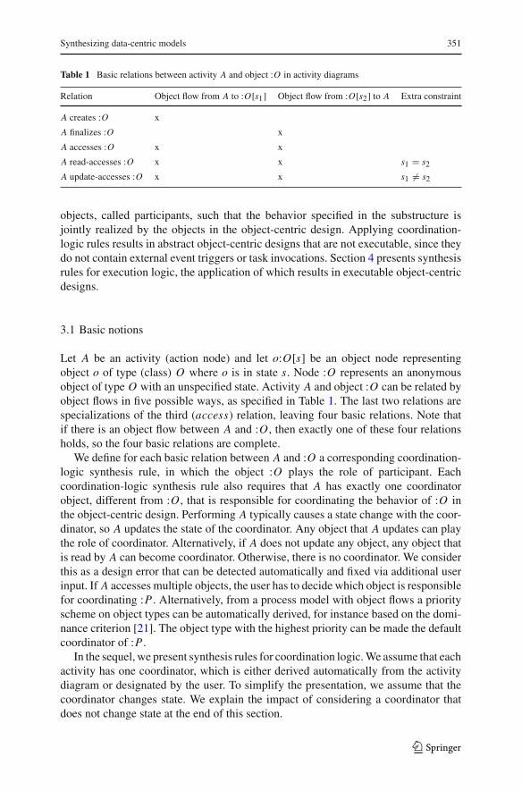
Table 1 Basic relations between activity A and object :O in activity diagrams
Relation Object flow from A to :O[s1] Object flow from :O[s2] to A Extra constraint
A creates :O x
A finalizes :O x
A accesses :O x x
A read-accesses :O x x s1 = s2A update-accesses :O x x s1 �= s2
objects, called participants, such that the behavior specified in the substructure isjointly realized by the objects in the object-centric design. Applying coordination-logic rules results in abstract object-centric designs that are not executable, since theydo not contain external event triggers or task invocations. Section 4 presents synthesisrules for execution logic, the application of which results in executable object-centricdesigns.
3.1 Basic notions
Let A be an activity (action node) and let o:O[s] be an object node representingobject o of type (class) O where o is in state s. Node :O represents an anonymousobject of type O with an unspecified state. Activity A and object :O can be related byobject flows in five possible ways, as specified in Table 1. The last two relations arespecializations of the third (access) relation, leaving four basic relations. Note thatif there is an object flow between A and :O , then exactly one of these four relationsholds, so the four basic relations are complete.
We define for each basic relation between A and :O a corresponding coordination-logic synthesis rule, in which the object :O plays the role of participant. Eachcoordination-logic synthesis rule also requires that A has exactly one coordinatorobject, different from :O , that is responsible for coordinating the behavior of :O inthe object-centric design. Performing A typically causes a state change with the coor-dinator, so A updates the state of the coordinator. Any object that A updates can playthe role of coordinator. Alternatively, if A does not update any object, any object thatis read by A can become coordinator. Otherwise, there is no coordinator. We considerthis as a design error that can be detected automatically and fixed via additional userinput. If A accesses multiple objects, the user has to decide which object is responsiblefor coordinating :P . Alternatively, from a process model with object flows a priorityscheme on object types can be automatically derived, for instance based on the domi-nance criterion [21]. The object type with the highest priority can be made the defaultcoordinator of :P .
In the sequel, we present synthesis rules for coordination logic.We assume that eachactivity has one coordinator, which is either derived automatically from the activitydiagram or designated by the user. To simplify the presentation, we assume that thecoordinator changes state. We explain the impact of considering a coordinator thatdoes not change state at the end of this section.
123

352 R. Eshuis, P. Van Gorp
Fig. 3 Synthesis rule for creation
Fig. 4 Synthesis rule for finalization
3.2 Creation
We consider the case that activity A creates an object of type P under coordinationof object :O . Figure 3 specifies the synthesis rule for creation. The activity diagramspecifies that by performing A, the state of :O moves from S1 to S2 and that anobject p:P is created whose first state is ini t . In the corresponding object life cycle,coordinator :O creates an object p of type P with action create(P) when movingfrom S1 to S2. Coordinator :O is also responsible for executing task A and waiting forits completion, but these details are defined by the synthesis rule for tasks in Sect. 4.
3.3 Finalization
Activity A finalizes object p:P under coordination of object :O by moving p:P intoits local end state, which has no successor state. Finalization does not mean that theobject is destroyed. The finalization is realized in the object life cycles (Fig. 4) byletting coordinator :O send a special event f inali ze to p:P , provided :P is indeedin the expected state T , modeled with guard condition p.in(T ). The f inali ze eventmoves the life cycle of p:P to the local end state. It might be that the life cycle of p:Phas multiple end states in different parallel branches; in that case, the other parallelbranches of the life cycle can still continue after this branch has been finalized.
3.4 Read-access
If activity A reads object p:P under coordination of :O , then :P does not change state.This means no transition is required in the object life cycle of p:P . However, the state
123

Synthesizing data-centric models 353
Fig. 5 Synthesis rule for read-access
Fig. 6 Synthesis rule for update-access
of P is a precondition for :O to change state, since A can only start if objects :O andp:P are present. Therefore, in Fig. 5 the coordinator state machine for :O can onlychange state if the current state of p:P is T .
3.5 Update-access
If activity A updates object p:P under coordination of :O , then both :O and p:P moveto a new state. The state change of p:P is triggered by :O . But coordinator :O mayonly generate an event for p:P if p has already reached the state that is preconditionto A. Figure 6 shows that :O generates an event toT 2 that triggers p:P to move to itsnext state, but only if p:P is currently in state T , since otherwise A cannot start.
3.6 Discussion
We next discuss two issues for the translation.
3.6.1 Coordinators with read-access
As explained in Sect. 3.1, the synthesis rules for coordination logic assume the coor-dinator changes state when activity A is performed. If the coordinator does not changestate, the rules need to be slightly adjusted. Denote the coordinator state with S. Allthe state machines for :O in the coordination rules can be adjusted by letting states S1and S2 become substates of composite state S. For instance, Fig. 7 shows the synthesis
123

354 R. Eshuis, P. Van Gorp
Fig. 7 Synthesis rule for update-access using coordinator with read-access
rule for update-access, modified from Fig. 6, in case the coordinator uses a read-accessfor A.
3.6.2 Multiple participants
In the discussion of the synthesis rules, we tacitly assumed that for each activity Athere is only one participant. In practice, however, there can be multiple participants.For instance, in Fig. 1 activity close order has coordinator o:Order and two partici-pants s:Shipment and b:Bill. In the case, the effects on the coordinator life cycle thatare obtained by applying the rule to each participant separately, must be combinedin the coordinator life cycle by joining all the guards and actions introduced for eachparticipant. For instance, in Fig. 2 the transition from dispatched to delivered for coor-dinator o:Order contains a conjunction of the guard conditions obtained by applyingthe finalization rule for both participants b:Bill and s:Shipment. Similarly, the transitiongenerates two events that are also the result of applying the finalization rule to eachparticipant.
4 Synthesis rules for execution logic
Synthesis rules for coordination logic only capture the object-flow constraints fromactivity diagrams. To capture control-flow constraints, we define synthesis rules forexecution logic. Each execution-logic synthesis rule translates a substructure whichcontains a basic control-flowconstruct (task, decision,merge, fork, join) into an object-centric design. These constructs are similar to the standard workflow patterns used inany process language [2].
4.1 Task
A task is invoked in an activity node. A typical distinction is between manual, auto-mated, and semi-automated tasks [1]. For this paper, we only consider automated tasks;we expect the generated designs can be adapted easily to other task types. Figure 8shows how a task invocation can be specified in an object-centric design. The coordina-
123

Synthesizing data-centric models 355
Fig. 8 Synthesis rule for tasks
tor :O is responsible for invoking task A; there its precondition state S1 is decomposedinto two states, where busy A denotes that activity A is being executed. The busy statecan be decomposed to model a more complex task life cycle, for instance allowingsuspension of a task [6]. However, we assume tasks are successful, so task abortion isnot considered. Upon completion, the coordinator moves to S2 and informs the otherobject p:P that it has to move to new state T 2. In Fig. 8, the underlying coordination-logic rule is update-access, but the synthesis rule for tasks can be combined with anycoordination-logic rule or be used independently if only a single object is involved.We discuss in Sect. 4.6 how the synthesis rule is applied to the example in Fig. 1.
4.2 Decision
An object node can have multiple outgoing flows. This represents exclusive (choice)behavior: exactly one of the outgoing flows is taken if the object node is active. Theactual decision is taken in the control flow, represented by a decision node.
Figure 9 shows the synthesis rule for decision nodes. In the activity diagram, stateS1 is precondition to both A and B; upon completion of either A or B object :O movesto S2 or S3. The object life cycle mimics this behavior. Upon entering state S1 of :O ,either A or B is invoked, where A can only be invoked if p:P is in state T 2. If A isinvoked, then also p:P must change state (update-access rule). As in the case of theprevious rule, the precondition state S1 is hierarchical. In this case, S1 contains thedecision logic to decide between A or B; note that this decision logic comes from thecontrol flow in the activity diagram.
4.3 Merge
Similar to the previous case, an object node with multiple incoming object flowsrepresents exclusive behavior: if one of the object flows is activated, the object node isentered. Again, the actual behavior is governed by control flow. The resulting synthesisrule for merge nodes shown in Fig. 10 is symmetric to the rule for decision nodes.
123

356 R. Eshuis, P. Van Gorp
Fig. 9 Synthesis rule for decision nodes
Fig. 10 Synthesis rule for merge nodes
Note that in the object life cycle for o:O states S1 and S2 are exclusive, so they cannotbe active in parallel at the same time.
4.4 Fork
So far, we have seen only sequential statemachines that do not contain any parallelism.However, an object can be in multiple states at the same time [16,41], each state beinga partial view of the global state. In activity diagrams, parallelism inside an objectlife cycle for object type O is introduced by an activity node that outputs multipleobject nodes belonging to O . Since activity nodes activate all outgoing object flows,all output object nodes are filled. Each output object node for O then represents aparallel branch in the life cycle for O . For examples, we refer to earlier work [9].
In the control flow of activity diagrams, parallelism is introduced by a fork node.Figure 11 shows how the resulting synthesis rule for fork nodes is specified. The
123

Synthesizing data-centric models 357
Fig. 11 Synthesis rule for fork nodes
state hierarchy is constructed using the approach we developed previously [9]. Thetwo concurrent states, separated with a dashed line, model the two parallel branchesstarted upon completion of A. The state hierarchy for S2 and S3 derives from thesynthesis rule for tasks. The state hierarchy for S1, also due to the task synthesis rule,is not shown to simplify the exposition.
4.5 Join
The rule for join nodes is symmetric to the one for fork nodes (Fig. 12). Complicatingfactor is to decide where in the life cycle task C should be invoked. Activity C syn-chronizes the parallel branches in the activity diagram. Similarly, the parallel branchesin the object life cycle for :O are only left if activity C completes. This implies thatin the life cycle for :O task C needs to be invoked in one of the parallel branches(since activity C is invoked only once in the activity diagram). But if C is invoked in abranch, the other parallel branch must be in the state that is precondition to C . Whichparallel branch is chosen to invoke C is arbitrary. In the figure, the task rule for C isapplied to S2. This means that C can only be invoked if the other parallel branch is instate S4.
4.6 Discussion
We highlight the most interesting issues of the translation defined in this section andthe previous one.
4.6.1 Interference
The synthesis rules for fork and join nodes introduce concurrency inside a businessobject, which may lead to interference if two concurrent tasks write the same data
123

358 R. Eshuis, P. Van Gorp
Fig. 12 Synthesis rule for join nodes
element. We do not handle interference in the approach, but interference can be pre-vented in different ways. First, orthogonal states can be required to access distinct dataelements. However, this may be too restrictive. Alternatively, if orthogonal states doaccess shared data elements, nested transactions [15] can be used by creating for eachstate a transaction and nesting a transaction t inside another transaction t ′ if the stateof t is descendant of the state of t ′ in the state machine. Nested transactions allow forrelaxed isolation between concurrent tasks in workflow management [45].
4.6.2 Order example
To obtain the state machines in Fig. 2 from the activity diagram in Fig. 1 all fourrules for coordination logic are required. Next, the task synthesis rule is used. Thedecision, merge, fork, and join control nodes in Fig. 1 all reference multiple objectsand therefore do not fit in any individual object life cycle. Consequently, the synthesisrules for these control nodes are not applicable for this example.
To derive the state machines in Fig. 2, first the activity diagram is copied andsliced per object type. Next, for each object type a flat state machine skeleton issynthesized using the approach defined in earlier work and summarized in Sect. 2.Then the coordination-logic rules are applied iteratively, which result in annotation ontransitions of the statemachines. Next, the synthesis rule for tasks is applied iteratively,which results in decomposition of the states that have been created for the object nodesin Fig. 1.
The decomposition of state dispatched in Fig. 2 is more complex than the otherstates because of activity send bill, where the coordinator o:Order uses a read-accessrather than update-access. Since send bill creates object bill, the synthesis rule forcreation needs to applied. Since the coordinator uses a read-access, a slightly modifiedversion of the rule in Fig. 3 is applied: S1 and S2 of coordinator :O are substates of thecomposite state S of :O , similar to the rule defined in Fig. 7. State init inside dispatched
123
Synthesizing data-centric models 359
in Fig. 2 resembles state S1 of object :O while send bill completed resembles S2. Next,state send bill completed is decomposed in order to invoke task receive arrival info,which needs to be executed after send bill.
4.6.3 Multiple start states
If an object life cycle has multiple start states that are created by parallel activities, thesynthesis approach will create multiple create actions. This results in multiple objectsrather than a single object with parallelism.
We consider multiple start states as a design error: two parallel activities that createthe same object :O suggest on the one hand that :O is created synchronously while onthe other hand the two activities execute independently from one another. This errorcan be repaired by merging the activities that create the object. Another option is toextend the object life cycle with a new, unique start state fromwhich the old start statescan be reached.
4.6.4 Multiple variables
The translation does not consider two different objects that reference the same objecttype but have different states. One option is to view such objects as two orthogonalaspects of the same object life cycle. Another option is to view the objects as indepen-dent subclasses of the object type, each subclass having its own life cycle. We deferfurther analysis of such models to future work.
5 From state machines to GSM schemas
We define a mapping from state machines constructed by the rules in Sects. 3 and 4to GSM schemas, a recent proposal for declarative, artifact-centric business processmanagement [7,19]. We introduce first the basics of GSM schemas, next the mapping,and finally the most salient features of the mapping.
5.1 GSM schemas
The core ingredients of a GSM schema are stages and milestones [19]. A milestonespecifies an operational business objective. A stage specifies a business activity per-formed to achieve a milestone. If a stage has multiple milestones, at most one of themcan be achieved at a time [19]. The GSM version we consider in this paper has beenpublished in citations [12,39] and allowsmilestones that are disconnected from stages.A GSM schema contains the following kind of rules:
– for each stage guard rules that specify when the stage is opened and terminationrules that specify when the stage is closed; and
– for each milestone achieving rules that specify when the milestone gets achievedand invalidation rules that specify when the milestone gets invalidated.
Each rule has the syntax ON e IF condition where e is an event and condition isa Boolean expression, possibly true. Both the ON-part and the IF-part are optional.
123

360 R. Eshuis, P. Van Gorp
Each change of a stage or milestone generates an event that can be referenced inrules. Event prefixes + and −indicate the kind of change: for milestone m event +moccurs if m gets achieved and −m occurs if m gets invalidated, and for stage S event+S occurs if S gets opened while −S occurs if S gets closed.
5.2 Mapping
To simplify the definition, we first identify two types of states for state machinesconstructed using the mapping defined in Sects. 3 and 4.
– In a busy state the system waits for an activity to complete. Each busy state doesnot contain any other states and has a label starting with “busy”.
– An object state corresponds directly to an object node in the activity diagram. Anobject state either contains no other states or is composite, without having anyparallel branches.
For instance, in the state machine of Bill (Fig. 2), state busy receiving payment isa busy state, while composite state unpaid and state paid are object states. The otherstates are neither busy nor object states.
By definition, a busy state is not an object state and vice versa. Based on thisclassification, we map state machines to GSM schemas. Object states are similar tomilestones while busy states are similar to stages. We exploit this correspondence inthe mapping defined below. However, not all properties of a generated state machinecan be captured in aGSMschema. By construction, a busy state is inside an object state(cf. Fig. 8). InGSM schemas, however, a stage cannot be nested inside amilestone, andtherefore the state machine hierarchy cannot be encoded directly in a GSM schema.
Wenowdefine amapping from statemachines as constructed using the rules definedin Sects. 3 and 4 to GSM schemas. We define the set of stages and milestones as wellas the rules that specify when the stages and milestones change status.
5.2.1 Stages
Each busy state in which task T is performed, maps into a stage ST in which T islaunched. By construction (cf. Fig. 8), the parent of the busy state is an object state thatmaps into a milestone m, defined below. The guard of ST becomes “ON +m”. If thebusy state follows a decision (cf. Fig. 9), the guard of ST is appended with “IF cond”,where cond is the condition of the decision branch in the state machine that leads tothe busy state for T . The termination rule of ST becomes “ON cpl(T )”.
For example, consider busy state busy completing order in Fig. 2,which is containedin object state open. We create a stage complete order, whose guard rule isON +open,for milestone open, and whose terminating rule is ON cpl(complete order).
5.2.2 Milestones
We define two sets of milestones with achieving and validating rules. For the first set,each state s that has an incoming transition t triggered by a completion event cpl(T ),
123

Synthesizing data-centric models 361
where T is a task, maps to a milestone ms . State s is either an object state (cf. Fig. 8)or a state containing parallel branches (cf. Fig. 11). An achieving rule “ON −ST ” isdefined for the milestone ms , so when the stage performing T is closed, the milestoneis achieved.
For example, for object state finalized in Fig. 2 a milestone finalized is created,whose achieving rule is ON −complete order, since the incoming transition of statefinalized has trigger cpl(complete order).
If s has an outgoing transitionwith trigger event cpl(T ) for some task T , then the tar-get state of the transitionmaps into amilestonem, as defined in the previous paragraph.The invalidating rule ofms becomes “ON+m”. For example, the invalidating rule formilestone open becomes ON +finalized. Otherwise, if s has no outgoing transitionwith trigger event cpl(T ) but is child of an object state forwhichmilestonem is created,milestone ms becomes invalid if parent milestone m becomes invalid, so the invali-dating rule of ms becomes “ON −m”. For instance, for state send bill completed inFig. 2 milestone send bill completed is created, whose parent milestone is dispatched.Therefore the invalidating rule for send bill completed becomesON −dispatched. Asanother example, for the milestonesmS2 andmS4 created for Fig. 12, the invalidatingrule becomes in both casesON−mc, wheremc is the milestone created for compositestate c in the figure. In all other cases, no invalidating rule is specified for ms .
For the second set, each object state s that has no incoming transition triggeredby a completion event maps into a milestone ms . Figure 11 contains two such objectstates: S2 and S3, which are both the initial states of a composite state that is enteredby a transition triggered by a completion event. Next, S2 and S3 are in parallel. Bydefinition of the first set of milestones, such a composite state c maps to milestonemc. In that case, the achieving rule ofms becomes “ON+mc”, so ifmc gets achieved,also ms gets achieved.
Alternatively, the object state s can have an incoming transition triggered by agenerated (non-completion) event e (cf. Fig. 6). In that case, the achieving rule formilestone ms becomes “ON e”. For example, for the Shipment object in Fig. 2 theachieving rule for milestone being shipped becomes ON leave.
Otherwise, the object state is the start state of the life cycle and the achieving ruleis trivially achieved by rule “IF true”.
The definition of the invalidating rule for milestone ms is similar to the one formilestones from the first set.
5.2.3 Example
Figures 13 and 14 show the stages and milestones and their rules for the Order arti-fact of Fig. 2 that are obtained by applying the translation defined above. Milestonesend bill completed has a different type of invalidating rule than the other milestones:the corresponding state send bill completed does not have an outgoing transition trig-gered by a completion event, but is contained inside an object state for whichmilestonedispatched is created. All milestones are from the first set, except openwhich belongsto the second set.
123

362 R. Eshuis, P. Van Gorp
Stages Guard rules Terminating rulescomplete order ON +open ON cpl(complete order)send shipment ON +finalized ON cpl(send shipment)send bill ON +dispatched ON cpl(send bill)receive arrival info ON +send bill completed ON cpl(receive arrival info)close order ON +delivered ON cpl(close order)
Fig. 13 Stages with their rules for Order artifact
Milestones Achieving rules Invalidating rulesopen IF true ON +finalizedfinalized ON -complete order ON +dispatcheddispatched ON -send shipment ON +deliveredsend bill completed ON -send bill ON -dispatcheddelivered ON -receive arrival info ON +closedclosed ON -close order
Fig. 14 Milestones with rules for Order artifact
5.3 Discussion
We next discuss the most salient features of the translation.
5.3.1 Refining
The constructed GSM schema is a skeleton that is to be further refined by adding dataattributes as well as additional stages, milestones and rules, for instance to incorporatehuman-centric behavior. To illustrate, suppose the companyof the order processwishesto allow that a customer cancels a finalized order that has not yet been paid by rejectinga sent bill. This means that an external cancellation event can occur which needs to beresponded to. Modeling the response by extending the global process model of Fig. 1results in a complex diagram with a lot of additional edges. In the GSM schema, onlya few local changes are required to model the response: extending the life cycle of theBill and Order artifacts with additional milestones that model cancellation plus newrules that specify the intended response if the cancellation event occurs.
5.3.2 Creation and communication
The GSM approach does not support explicit create and communication actions.Rather, GSM tasks are responsible for creating new artifacts and generating events thatare sent to other artifacts [20]. The tasks in the object-centric design of Fig. 2 do nothave this functionality. Consequently, the GSM schema for Order of which the coreelements are specified in Figs. 13 and 14 is less detailed than the object-centric modelforOrder in Fig. 2, at the expense of more complex GSM task implementations to real-ize the creation of artifacts and generation of events. For instance, a Shipment objectis created by the Order object in the design of Fig. 2, but in a GSM implementationtask Complete order should be responsible for creating the Shipment artifact instanceand returning an ID for this instance. Likewise, the generation of events leave, arriveand finalize by Order for Shipment in Fig. 2 must be implemented by GSM tasks.
123

Synthesizing data-centric models 363
5.3.3 Direct vs. indirect mapping
Anatural question iswhether a directmapping fromactivity diagrams toGSMschemaswould not be preferable. An obvious mapping would be to translate every activity withn outgoing object nodes into a stagewith nmilestones attached. However, themeaningof an activity in UML [41] is that it simultaneously produces n different objects, whilemilestones attached to a stage are exclusive [19], i.e., at most one milestone at atime can be true. Another mismatch is that an activity can produce different types ofobjects (artifacts), while a stage that encapsulates a task is always local to one artifact.These two mismatches between activity diagrams and GSM schemas considerablycomplicate defining a direct mapping from activity diagrams to GSM schemas.
Using an intermediate state machine model helps to resolve the two mismatchesas follows. The synthesis rules for fork and join nodes in Sects. 4.4 and 4.5 introducecomposite states containing parallel branches; these states translate into milestones.For instance, the composite state in Fig. 11 translates into amilestonem, since it has anincoming transition triggered by a completion event. Milestonem belongs to the stagein which task A is launched. The object states S2 and S3 translate into milestones fromthe second set, which get achieved if the milestonem gets achieved; they do not belongto any stage. This resolves the first mismatch. The second mismatch is resolved by thesynthesis rule for tasks, which allocates an activity to the coordinator of the activity.
6 Implementation
To evaluate the feasibility of the approach, we implemented the synthesis rules in aprototype. For the implementation, we build upon previous work on the transformationof Petri nets to UML state machines [43]. In turn, that line of work builds uponGrGen.NET [14], a generic graph transformation infrastructure not specific to BPM.In this section, we describe the overall architecture of our implementation. Appendixprovides a gentle introduction to the source code, to stimulate the reader to leverageour open source materials.
Figure 15 provides a dynamic view on the architecture of our implementation.Each thick arrow represents a step in the transformation process. At the most abstractlevel, the figure shows that the humanmodeler only interacts with a professional UMLeditor; all processing steps are automated.
Step 1© represents the step of exporting the inputUMLactivity diagram to a standardformat. Our current implementation supports XMI based on the UML metamodel inversion 2.2 from theObjectManagement Group. All examplemodels have been editedusing MagicDraw 16.6 but other tools conforming to the standard can be used too.Steps 2© to 9© are fully automated. Step 2© consists of a simple syntactic translation.The output of this step is an input script for GrGen.NET. In Step 3©, this script isexecuted by the GrGen.NET shell interpreter. This results in a graph representationof the UML activity diagram. The graph is typed according to the various elementsfrom the UML metamodel. The type graph is used to check among others whethercardinality constraints are satisfied in the input model.
123

364 R. Eshuis, P. Van Gorp
Fig.1
5Architectureof
theIm
plem
entatio
n
123

Synthesizing data-centric models 365
Step 4© is the start of the conceptual translation work. In this step, the graph rep-resenting the activity diagram is cloned once for each object type. Also, traceabilitylinks are generated between source and target elements. In Fig. 15, traceability linksare sketched as dotted edges. For the figure, we assume three object types, resultingin three copied UML instance graphs. The GrGen.NET platform provides checks forensuring that metamodel constraints are preserved throughout the cloning process.Finally, note that right before the cloning, it should be decided which object typesact as the Coordinators of the various activities. Our implementation can mark validCoordinators automatically or it can let an expert select among valid candidates. Fig-ure 15 does not show that since our prototype has no end-user oriented UI widgetsfor this optional interaction step. For industrial settings, one may build a user-friendlyUML tool plug-in for the Coordinator selection.
In Step 5©, the cloned activity diagrams are sliced per object type: first of all, onlyobject nodes of one specific type are preserved per slice. Additionally, filtering rulesremove gateways that are irrelevant for the sliced object life cycle. The filtering rulesare reused from [9] (since they were also needed for process flows involving just oneobject type) while the cloning and slicing rules are new for this paper.
The synthesis of filtered activity diagrams to state machines, defined in earlierwork [9], is implemented by first mapping activity diagrams to Petri nets (Step 6©)and next applying in Step 7© Petri-net reduction rules that construct a state machinewith state hierarchy [8,43] to the generated Petri nets. This results in a valid statemachine for a Petri net if the net has been reduced to exactly one place. As elaboratedin previous work [42], the tool chain generates end-to-end traceability links (fromactivity diagram elements to state machine elements), which is non-trivial given thedestructive effect of the Petri-net reduction rules that construct state hierarchy [8].The reduction rules can deal also with semi-structured processes involving cross-synchronizations between concurrent regions.
After the reduction rules [8,43] have completed, Step 7© performs additional sub-steps specific to this paper. First, it annotates the statemachineswith trigger, guard andeffect (action) labels. This is realized by rules that implement the new coordination-logic rules from Sect. 3. Finally, rules are executed for realizing the execution-logicrules from Sect. 4, e.g. inserting nested flows.
In Step 8©, the transformation chain dumps the generated state machines to a textfile. More specifically, the state machine instance graphs are mapped to text fragmentsbased on theUMLandXMI standards. In Step 9©, the human expert opens thatXMIfilein a professional UML editor. Tools such as MagicDraw implement automatic layoutalgorithms that perform well for life cycle models, since these tend to be simple instructure.
A strength of our architecture is its modularity: we incrementally build upon priorwork and we have avoided changes to the reused parts. As indicated above, the imple-mentation described in citation [43] has been reused in Step 6© and in the first phaseof Step 7©. The second phase of that latter step involves new rules (regarding Sects. 3and 4) but these additions are incremental. As a second example of modularity, thefiltering rules defined in citation [9] are applied without changes in the second phase ofStep 5©. The newcloning rules (cf. Step 4©) andfiltering rules (cf. phase twoof Step 5©)have been added incrementally to the transformation chain of prior work [9,43].
123

366 R. Eshuis, P. Van Gorp
In future work, we plan to implement the translation defined in Sect. 5. The targetlanguage will be CMMN [5]. Since the GSM constructs are directly supported inCMMN, we do not expect any implementation issues.
7 Related work
As stated in the introduction, in the last years a lot of research has been per-formed in the area of data-centric process modeling approaches such as businessartifacts [18,21,29,46], case management [3,40], data-driven process models that areexecutable [22,28,33] and process models with data flow [25,27,38,44]. Sanz [37]surveys previous work on integrating the data and process perspective in the field ofentity-relation modeling in connection to data-centric process modeling. This paperuses UML activity diagrams with object flows as data-centric process modeling nota-tion but we also show how the resulting object-centric designs can be mapped todeclarative, artifact-centric schemas [19].
We first discuss in detail existing transformation approaches between activity-centric and data-centric processmodels. Next, we discussmodeling approaches relatedto the ones used in this paper.
7.1 Transformation approaches
Related to this paper are approaches that distinguish between process and data modelsand bridge the gap by deriving a process model that is coherent with a predefined datamodel [17,35] or object behavior model [13,23,32]. This paper takes the oppositeroute: it considers a process model with data (object) flow and derives object behaviormodels that realize the process model.
More related are a few works [21,24,26,44] that define a translation betweenactivity-centric and object-centric process models, which consist of communicatingobject life cycles. As the process models in this paper, activity-centric process modelsmanipulate stateful business objects, where each step in a process model can leadto a change in one or more business objects. The main differences are therefore inthe considered data-centric process models. Both Kumaran et al. [21,24] and Meyerand Weske [26] use synchronized object life cycles, which are flat, sequential statemachines that synchronize on shared activities. Event communication between objectsand task invocations are not specified by these state machines. In contrast, the objectlife cycles (UML state machines) generated by our approach are hierarchical, allowparallelism, deal with task invocations, and use asynchronous event communication,in line with UML [41].
Because the modeling notation for object life cycles is more complex, also themapping to object life cycles defined in this paper is more involved than the othermappings [21,24,26], which are specified by relatively simple algorithms. We usesynthesis rules in Sects. 3 and 4 to avoid defining a single, complex algorithm.Kumaranet al. [21,24] focus on the problem how to identify the objects in the process modelfor which an object life cycle should be constructed, while we construct an objectlife cycle for every stateful object. Like us, Kumaran et al. derive object life cycles
123

Synthesizing data-centric models 367
from the syntax of process models, whereasMeyer andWeske [26] construct an objectlife cycle by processing each trace of a process model. Disadvantage of a trace-basedmapping is that the same nodes (activity or object nodes) can occur in multiple traces,resulting in object life cycles with duplicate states.
Next, Meyer and Weske [26] also consider an artifact-centric process model con-sisting of business rules. Each rule consists of a pre and postcondition on objects plusa set of tasks that manipulate objects to achieve the postcondition. Such a rule roughlycorresponds to a GSM stage whose guard is the precondition and a GSM milestonethat is achieved when the postcondition is fulfilled.
Wahler and Küster [44], based on earlier work [36], use as target implementationmodel a static set of predefined business objects that need to be “wired” together,where the activity-centric process model is used to derive the wiring relation. Theystudy how to design the wiring in such a way, by changing the process model, that theresulting wired object design has a low coupling. In contrast, this paper studies theproblem of deriving an object-centric design from a process model with object flows.The problem is then defining the set of business objects and their behavior, which areboth given in the approach of Wahler and Küster.
To the best of our knowledge, there is only one other paper that discusses a trans-lation into GSM schemas. Popova and Dumas [31] define a mapping from classicalPetri nets to GSM schemas. They focus on tasks, modeled by Petri net transitions, anddo not consider object flows. Therefore their mapping is not applicable to the UMLactivity diagrams we consider in this paper. Their translation is complicated by thepresence of invisible transitions in Petri nets, which do not occur in activity diagramsand state machines. Each visible Petri net transition maps to a stage with an accom-panying milestone that is achieved when the stage completes. Places are not used inthe translation. To mimic the token-flow of Petri nets faithfully in GSM schemas, theyneed to use complex rules. For example, if a Petri net transition consumes a tokenthat can also be consumed by another transition, then in the guard of the created stagetime stamps of milestone changes are compared. Our guard rules for stages are muchmore simple due to the more structured syntax of UML state machines: each transitionconnects two states that cannot be simultaneously active. Consequently, achieving themilestone created for the target state of a transition invalidates themilestone created forthe source state, as illustrated in Fig. 14 in Sect. 5. Drawback of UML state machinesis that unlike Petri nets, they cannot directly express cross-synchronization betweenparallel branches of an object life cycle. In previous work [11], we have defined aspecific translation rule based on event synchronization for such cases.
Bhattacharya et al. [4] propose a data-centric design methodology in which GSM-like schemas are constructed step by step. The focus is on defining different lifecycles for different artifacts from scratch, which may complicate for stakeholders theunderstanding of the overall default behavior. The approach we propose complementstheirs, since it allows to develop a global process model that specifies the defaultbehavior of the artifacts (objects). The mapping defined in Sect. 5 can be used togenerate starting definitions for the artifacts, which can be further refined by applyingthe methodology of Bhattacharya et al. [4].
123

368 R. Eshuis, P. Van Gorp
7.2 Modeling techniques
The first part of the approach is defined in the context of UML activity diagrams [41],which model business processes in an imperative, activity-centric way. The synthesisrules of Sects. 3 and 4 are directly applicable to any imperative process modelinglanguage that uses a similar semantics for object flows as UML activity diagrams; forinstance, an activity can only start if its input objects are present, so read-access ismandatory [34].
BPMN [30] supports a similar object-flow notation as UML activity diagrams, butthe BPMN semantics is different for some models. UML uses a token-flow semanticsfor objects. For instance, if an object node is read via an outgoing object flow, theobject (token) moves to the target of the object flow and is no longer available forother outgoing object flows of the object node, as explained in Sect. 2. WhereasBPMN uses a copy semantics for objects: if available, the input object of a BPMNobject flow, called data association, is copied to the output [30]. This implies thatif a BPMN object node, called data object, is read via an outgoing data association,the read object remains available for the other outgoing data associations. So whilea UML object node with multiple outgoing object flows specifies exclusive behavior,a BPMN data object with multiple outgoing data associations does not. However, ifin a BPMN model every data object has at most one incoming and one outgoing dataassociation, its behavior is similar to an activity diagram. The rules defined in thispaper can be applied to such BPMN models with little modification, only replacingthe UML activity diagram concepts by their BPMN counterparts.
As alternative for GSM schemas, case management [3,40] or object-aware processmanagement [22] could be used as target framework. A discussion of the similari-ties and differences between these approaches is outside the scope of this paper, butReichert and Weber present an overview [34]. Note that all these data-centric frame-works allow formuchmore fine-grained behavior than can be expressed inUML activ-ity diagrams [41] or related imperative process modeling notations like BPMN [30].For instance, enabling of an activity can depend on specific attribute values of multi-ple, related object instances. Such fine-grained behavior can be added by refining theinitial data-centric process design obtained by applying the synthesis approach.
Most data-centric process management approaches [3,19,22] also allow to designprocess models using an activity-centric style. For instance, it is possible in GSMschemas to use a flow-style modeling that resembles imperative, activity-centric mod-eling [19]. The default behavior of a business process can therefore also be modeleddirectly using a data-centric process modeling approach instead of UML activity dia-grams.However, these data-centric approacheswere never intended to develop impera-tive, activity-centricmodels: their strength is the flexible specification and execution ofdata-centric processes. While the strength of imperative process modeling techniqueslike UML activity diagrams is that they clearly and concisely specify default behaviorof a business process. For this reason, we propose to model the default behavior ofprocesses in an imperative, activity-centric way and have defined an approach to trans-form them in data-centric process models. The resulting data-centric process designscan be further refined and extended to deal with anticipated exceptional circumstances,which is the strength of data-centric process management approaches [3,19,22].
123

Synthesizing data-centric models 369
Finally, Meyer et al. [27] take a different approach to solve the tension betweenactivity-centric and data-centric process models. Based on a subset of requirementsidentified byKünzle andReichert [22], they address shortcomings ofBPMN in the areaof data-centric process management. In particular, they introduce BPMN annotationsto specify data-centric behavior and define SQL queries that realize these annotations.While their approach is supported by state-of-the-art process- and data-managementtechnology, it does not support the full range of options supported by data-centricapproaches [3,19,22].
8 Conclusion
We have presented a semi-automated approach that synthesizes an object-centricsystem design from a business process model that references multiple objects. Theapproach distinguishes between coordination-logic synthesis rules that realize object-flow constraints and execution-logic rules for control-flow constraints. The rules heav-ily use the state hierarchy for the object life cycles to establish a clear link with theprocess model constructs. We have implemented and tested the rules in a prototypebased on graph-transformation technology [14].
The resulting object-centric design can be used to perform the process in a flexibleway [32]. We showed this by mapping object life cycles to Guard-Stage-Milestoneschemas, which have inspired the emerging OMG standard on case management(CMMN) [5]. We expect the proposed translation carries over directly to CMMN.Future work includes connecting the prototype to CMMN tools.
The approach is defined in the context of UML [41], but we plan to define a similarapproach for BPMN [30]. As explained in Sect. 7, BPMN uses a similar object-flownotation as UML activity diagrams but with a different semantics in certain cases.
The approach can also be extended to deal with more advanced UML activitydiagram constructs, for instance activities that can be instantiated multiple times inparallel or iteratively to process a collection of objects. Object-aware frameworks likePHILharmonicFlows [22] support such functionality, but also allow much more fine-grained synchronization among multiple objects and activities. In line with designmethod proposed in Sect. 1, such fine-grained synchronization can then be added in arefinement step.
In this paper, we envision that the data-centric process design generated using theapproach can be further refined by specifying responses to exceptional circumstances.This does imply that these circumstances need to be anticipated [34]. For imperativeprocesses, adaptive process management technology has been proposed to deal withunanticipated events at run-time [34]. Though adaptive processmanagement still needsto be developed for data-centric processes [22,34], we do expect that it can deal in thefuture with unanticipated events for data-centric processes.
Open Access This article is distributed under the terms of the Creative Commons Attribution Licensewhich permits any use, distribution, and reproduction in any medium, provided the original author(s) andthe source are credited.
123

370 R. Eshuis, P. Van Gorp
Appendix: Source code and online demonstrator
We provide open access to the source code of the prototype via GitHub.1 That onlinerepository provides access to sources for steps 2© to 8© from Fig. 15. In particu-lar, folder ad2grgen contains a Java based tool for step 2©. Folder grgen2sc pro-vides rules and transformation scripts for the GrGen.NET platform [14]. Source fileUML23AD.grg contains the heart of the implementation. In the following, wewalk thereader through the implementation of one specific rule that is defined in that file. Thatshould provide sufficient insight for exploring the other rules online. Since installingthe GrGen.NET platform may be a burden to many readers, we also provide an onlinedemonstrator in the form of a remotely accessible virtual machine.2
1 rule Add_GuardsTriggersAndEffectsForCoordinator {2 c:UmlClass <-:smType - cbnS1:CentralBufferNode -:ObjectFlow -> a:ActivityNode -:ObjectFlow
-> cbnS2:CentralBufferNode -:smType -> c;
3 a -:Coordinator -> c;4 negative { a -:VisitedEdge -> c; }5 cbnS1 -:AN2SC -> s1:SC_State;6 cbnS2 -:AN2SC -> s2:SC_State;7 s1 -trans:SC_Transition -> s2;8 iterated {9 alternative {
10 UFR { // Generic for Update/Finalize/Read11 cbnT1:CentralBufferNode -:ObjectFlow -> a;12 scbnT1:State <-:inState - cbnT1 -:smType -> c2:UmlClass;13 cbnT1 -:AN2SC -> t1:SC_State;14 negative { cbnT1 -:VisitedEdge -> a; }15 alternative {16 Update { // Update Rule17 a -:ObjectFlow -> cbnT2:CentralBufferNode -:smType -> c2;18 cbnT2 -:inState -> scbnT2:State;19 cbnT2 -:AN2SC -> t2:SC_State;20 t1 -trans2:SC_Transition -> t2;21 modify {22 eval {23 trans.effect= cbnT2.name+’’.to’’+scbnT2.name+’’ ’’+trans.effect;24 trans2.trigger= ’’to’’+scbnT2.name+’’ ’’+trans.trigger;25 }26 }27 }28 Finalize { /* Finalize Rule omitted from paper */ }29 Read { /* Read Rule: no extra modify */ a -:ObjectFlow -> cbnT1; }30 }31 modify {32 cbnT1 -:VisitedEdge -> a;33 eval {34 trans.guard=’’[’’+cbnT1.name+’’.in(’’+scbnT1.name+’’)] ’’+trans.guard;35 }36 }37 }38 Create { // Create Rule39 a -:ObjectFlow -> cbnInit:CentralBufferNode;40 cbnInit -:smType -> typeOf_cbnInit:UmlClass;41 negative {42 cbnOther:CentralBufferNode -:ObjectFlow -> a;43 cbnOther -:smType -> typeOf_cbnInit;44 }45 modify {46 eval {47 trans.effect=cbnInit.name+’’:= create(’’+cbnInit._type+’’)’’;48 }49 }50 }51 }52 }53 modify {54 a -:VisitedEdge -> c;55 }56 }
The listing defines a graph transformation rule named “Add_GuardsTriggersAnd-EffectsForCoordinator”. The ruleshould be executed as long as possible during the
1 See https://github.com/pvgorp/AD2SC.2 See http://share20.eu/?page=ConfigureNewSession&vdi=Win7_AD2SC_i.vdi.
123

Synthesizing data-centric models 371
second phase of Step 7© in the transformation chain (cf. Fig. 15). The termination ofthe rule is handled by requiring in its matching part the absense of an edge (cf. line 4)of type VisitedEdge while generating exactly such a link in the side-effects part ofthe rule (cf. line 54). The example rule realizes the full behavior of the Coordinatorsynthesis rules from Sect. 3. Below, we further clarify the transformation languagesyntax by example. A comprehensive manual of the GrGen.NET syntax and executionenvironment is available online.3
Line 2 declares via “c:UmlClass” a node variable c of type UmlClass. Line 3specifies that this node should be the Coordinator for activity a, by requiring thatthere is a special edge from a to c (the expression “− : Coordinator− >” defines ananonymous variable for a directed edge of typeCoordinator). The creation of that edgeis handled by another rule, which is executed during Step 4© in in the transformationchain (cf. Fig. 15). Line 3 only checks for the existence of the edge. Line 2 also statesthat c is the type of two object nodes: cbnS1 (which has an outgoing object flow toactivity a) and cbnS2 (which has an incoming object flow starting from a). Together,lines 2 and 3 specify textually a rule that formally represents the shared parts of Figs. 3,4, 5 and 6.
Lines 5 to 7 further specify the matching part of the rule. The expressions “− :AN2SC− >” require the presence of traceability links from the two object nodes inthe activity diagram to their corresponding state machine elements (two nodes of typeSC_State). At line 7, the name “trans” is bound to the edge variable that representsthe transition between these states.
A detailed explanation of the remainder of the code is omitted for the sake ofbrevity. Do note that via constructs such as iterated, the rule is applied maximally tothe host graph, ensuring that it also works in case multiple update rules apply to thesame UML activity. Also note that via the alternative construct, the variation betweenthe different Coordination synthesis rules (cf. Figs. 3, 4, 5 and 6) is handled withoutduplicating code. Finally, note that all expressions within amodify clause realize side-effects. Within the example code, most side-effects relate to updating the labels withinthe state machine graph. For example, the expression on line 47 updates the effectattribute of the trans variable that was matched via the rule pattern on line 7.
References
1. van der Aalst WMP, van Hee KM (2002) Workflow management: models, methods, and systems. MITPress, USA
2. van der AalstWMP, ter Hofstede AHM,Kiepuszewski B, Barros AP (2003)Workflow patterns. DistribParallel Databases 14(1):5–51
3. van der Aalst WMP, Weske M, Grünbauer D (2005) Case handling: a new paradigm for businessprocess support. Data Knowl Eng 53(2):129–162
4. Bhattacharya K, Hull R, Su J (2009) A data-centric design methodology for business processes. In:Handbook ofResearch onBusiness ProcessManagement, Information Science Publishing, pp 503–531
5. Bizagi et al. (2013) Case Management Model and Notation (CMMN). Object Management Group,OMG Document Number dtc/2013-01-01
3 http://www.info.uni-karlsruhe.de/software/grgen/GrGenNET-Manual.
123

372 R. Eshuis, P. Van Gorp
6. CoalitionWM (1997)Workflowmanagement coalition workflow client application (interface 2) appli-cation programming interface (WAPI) specification
7. Damaggio E, Hull R, Vaculín R (2013) On the equivalence of incremental and fixpoint semantics forbusiness artifacts with guard-stage-milestone lifecycles. Inf Syst 38(4):561–584
8. Eshuis R (2009) Translating safe petri nets to statecharts in a structure-preserving way. In: CavalcantiA, Dams D (eds) FM. Lecture Notes in Computer Science, vol 5850. Springer, pp 239–255
9. Eshuis R, Van Gorp P (2012) Synthesizing object life cycles from business process models. In: AtzeniP, Cheung DW, Ram S (eds) Proceedings of ER 2012. Lecture Notes in Computer Science, vol 7532.Springer, pp 307–320
10. Eshuis R, Van Gorp P (2014a) Synthesizing object-centric models from business process models. In:Lohmann N, Song M, Wohed P (eds) Proceedings of Business Process Management Workshops 2013,Revised Papers. Lecture Notes in Business Information Processing, vol 171. Springer, pp 155–166
11. Eshuis R, Van Gorp P (2014b) Synthesizing object life cycles from business process models. SoftwSyst Model. doi:10.1007/s10270-014-0406-4 (in press)
12. Eshuis R, Hull R, Sun Y, Vaculín R (2014) Splitting GSM schemas: A framework for outsourcing ofdeclarative artifact systems. Inf Syst 46:157–187. An early version appeared. In: Daniel F, Wang J,Weber B (eds) BPM 2013. Lecture Notes in Computer Science, vol 8094. Springer, pp 259–274
13. Fritz C, Hull R, Su J (2009) Automatic construction of simple artifact-based business processes. In:Fagin R (ed) ICDT, ACM, ACM International Conference Proceeding Series, vol 361, pp 225–238
14. Geiß R, Kroll M (2008) GrGen.NET: A fast, expressive, and general purpose graph rewrite tool. In:Rensink A, Täntzer G (eds) AGTiVE 2007, Kassel, October 10–12, 2007, Revised Selected and InvitedPapers, Springer, LNCS, vol 5088, pp 568–569
15. Gray J, Reuter A (1993) Transaction processing: concepts and techniques. Morgan Kaufmann, USA16. Harel D, Gery E (1997) Executable object modeling with statecharts. IEEE Comput 30(7):31–4217. vanHeeKM,Hidders J,HoubenGJ, Paredaens J, ThiranP (2009)On the relationship betweenworkflow
models and document types. Inf Syst 34(1):178–20818. Hull R (2008)Artifact-centric business processmodels: Brief survey of research results and challenges.
In: Meersman R, Tari Z (eds) OTM Conferences (2). Lecture Notes in Computer Science, vol 5332.Springer, pp 1152–1163
19. Hull R, Damaggio E, Fournier F, Gupta M, Heath FT, Hobson S, Linehan MH, Maradugu S, Nigam A,Sukaviriya P, Vaculín R (2010) Introducing the guard-stage-milestone approach for specifying businessentity lifecycles. In: Bravetti M, Bultan T (eds)WS-FM. Lecture Notes in Computer Science, vol 6551.Springer, pp 1–24
20. Hull R, Damaggio E,Masellis RD, Fournier F, GuptaM, Heath FT, Hobson S, LinehanMH,MaraduguS, NigamA, Sukaviriya PN, Vaculín R (2011) Business artifacts with guard-stage-milestone lifecycles:managing artifact interactions with conditions and events. In: Eyers DM, Etzion O, Gal A, Zdonik SB,Vincent P (eds) ACM, DEBS, pp 51–62
21. Kumaran S, Liu R, Wu FY (2008) On the duality of information-centric and activity-centric models ofbusiness processes. In: Bellahsene Z, Léonard M (eds) CAiSE. Lecture Notes in Computer Science,vol 5074. Springer, pp 32–47
22. Künzle V, Reichert M (2011) Philharmonicflows: towards a framework for object-aware process man-agement. J Softw Maint 23(4):205–244
23. Küster JM, Ryndina K, Gall H (2007) Generation of business process models for object life cyclecompliance. In: Alonso G, Dadam P, Rosemann M (eds) BPM. Lecture Notes in Computer Science,vol 4714. Springer, pp 165–181
24. Liu R, Wu FY, Kumaran S (2010) Transforming activity-centric business process models intoinformation-centric models for soa solutions. J Database Manag 21(4):14–34
25. Meyer A, Weske M (2012) Data support in process model abstraction. In: Atzeni P, Cheung DW, RamS (eds) Proceedings of ER 2012. Lecture Notes in Computer Science, vol 7532. Springer, pp 292–306
26. Meyer A, Weske M (2014) Activity-centric and artifact-centric process model roundtrip. In: LohmannN, Song M, Wohed P (eds) Proceedings of Business Process Management Workshops 2013, RevisedPapers. Lecture Notes in Business Information Processing, vol 171. Springer, pp 167–181
27. Meyer A, Pufahl L, Fahland D, Weske M (2013) Modeling and enacting complex data dependenciesin business processes. In: Daniel F, Wang J, Weber B (eds) Proceedins of BPM 2013. Lecture Notesin Computer Science, vol 8094. Springer, pp 171–186
123

Synthesizing data-centric models 373
28. Müller D, Reichert M, Herbst J (2007) Data-driven modeling and coordination of large process struc-tures. In: Meersman R, Tari Z (eds) OTM Conferences (1). Lecture Notes in Computer Science, vol4803. Springer, pp 131–149
29. Nigam A, Caswell NS (2003) Business artifacts: an approach to operational specification. IBM Syst J42(3):428–445
30. (OMG) OMG (2011) Business process model and notation (bpmn) version 2.0. Tech. rep31. Popova V, Dumas M (2013) From Petri nets to guard-stage-milestone models. In: Rosa ML, Soffer P
(eds) Proceedings of Business Process Management Workshops 2012, Revised papers, Lecture Notesin Business Information Processing, vol 132. Springer, pp 340–351
32. Redding G, Dumas M, ter Hofstede AHM, Iordachescu A (2008) Generating business process modelsfrom object behavior models. IS Manag 25(4):319–331
33. Redding G, Dumas M, ter Hofstede AHM, Iordachescu A (2010) A flexible, object-centric approachfor business process modelling. Serv Oriented Comput Appl 4(3):191–201
34. Reichert M, Weber B (2012) Enabling Flexibility in process-aware information systems: challenges,methods, technologies. Springer, Berlin
35. Reijers HA, Limam S, van der Aalst WMP (2003) Product-based workflow design. J Manag Inf Syst20(1):229–262
36. Ryndina K, Küster JM, Gall H (2006) Consistency of business process models and object life cycles.In: Kühne T (ed) MoDELS Workshops. Lecture Notes in Computer Science, vol 4364. Springer, pp80–90
37. Sanz JLC (2011) Entity-centric operations modeling for business process management: a multidis-ciplinary review of the state-of-the-art. In: Lu X, Younas M, Zhu H, Gao JZ (eds) SOSE, IEEE, pp152–163
38. SunSX,Zhao JL,Nunamaker JF, ShengORL (2006) Formulating the data-flowperspective for businessprocess management. Inf Syst Res 17(4):374–391
39. Sun Y, Hull R, Vaculín R (2012) Parallel processing for business artifacts with declarative lifecycles.In: Meersman R, Panetto H, Dillon TS, Rinderle-Ma S, Dadam P, Zhou X, Pearson S, Ferscha A,Bergamaschi S, Cruz IF (eds) OTM Conferences (1). Lecture Notes in Computer Science, vol 7565.Springer, pp 433–443
40. Swenson KD (2010) Mastering the unpredictable: how adaptive case management will revolutionizethe way that knowledge workers get things done. Meghan-Kiffer Press, USA
41. UML Revision Taskforce (2010) UML 2.3 Superstructure Specification. Object Management Group,oMG Document Number formal/2010-05-05
42. Van Gorp P (2011) Applying traceability and cloning techniques to compose input-destructive modeltransformations into an input-preserving chain. In: 1st Workshop on Composition and Evolution ofModel Transformations, King’s College, London, UK
43. VanGorpP, EshuisR (2010)Transforming processmodels: executable rewrite rules versus a formalizedjava program. In: Petriu DC, Rouquette N, Haugen Ø (eds) MoDELS (2). Lecture Notes in ComputerScience, vol 6395. Springer, pp 258–272
44. Wahler K, Küster JM (2008) Predicting coupling of object-centric business process implementations.In: Dumas M, Reichert M, Shan MC (eds) BPM. Lecture Notes in Computer Science, vol 5240.Springer, pp 148–163
45. Wang T, Vonk J, Kratz B, Grefen PWPJ (2008) A survey on the history of transaction management:from flat to grid transactions. Distrib Parallel Databases 23(3):235–270
46. Yongchareon S, Liu C, Zhao X (2011) An artifact-centric view-based approach to modeling inter-organizational business processes. In: Bouguettaya A, Hauswirth M, Liu L (eds) WISE. Lecture Notesin Computer Science, vol 6997. Springer, pp 273–281
123


![[3.6] Beyond Data Sharing - Pieter van Gorp [3TU.Datacentrum Symposium 2014, Eindhoven]](https://static.fdocuments.us/doc/165x107/55837509d8b42ac1268b47c1/36-beyond-data-sharing-pieter-van-gorp-3tudatacentrum-symposium-2014-eindhoven.jpg)