SYNTHESIS AND CHARACTERIZATION OF CROSS-LINKED …
89
SYNTHESIS AND CHARACTERIZATION OF CROSS-LINKED WATER- DISPERSIBLE CONJUGATED POLYMER NANOPARTICLES A THESIS SUBMITTED TO THE DEPARTMENT OF CHEMISTRY AND THE GRADUATE SCHOOL OF ENGINEERING AND SCIENCE OF BILKENT UNIVERSITY IN PARTIAL FULFILLMENT OF THE REQUIREMENTS FOR THE DEGREE OF MASTER OF SCIENCE By ŞEYMA EKİZ APRIL 2012
Transcript of SYNTHESIS AND CHARACTERIZATION OF CROSS-LINKED …

SYNTHESIS AND CHARACTERIZATION OF CROSS-LINKED WATER-
DISPERSIBLE CONJUGATED POLYMER NANOPARTICLES
A THESIS
SUBMITTED TO THE DEPARTMENT OF CHEMISTRY AND THE GRADUATE
SCHOOL OF ENGINEERING AND SCIENCE OF BILKENT UNIVERSITY
IN PARTIAL FULFILLMENT OF THE REQUIREMENTS FOR THE DEGREE OF
MASTER OF SCIENCE
By
ŞEYMA EKİZ
APRIL 2012

i
I certify that I have read this thesis and in my opinion it is fully adequate, in scope and in
quality, as a thesis of the degree of Master of Science.
Assoc. Prof. Dr. Dönüş TUNCEL
I certify that I have read this thesis and in my opinion it is fully adequate, in scope and in
quality, as a thesis of the degree of Master of Science.
Prof. Dr. Engin Umut AKKAYA
I certify that I have read this thesis and in my opinion it is fully adequate, in scope and in
quality, as a thesis of the degree of Master of Science.
Assist. Prof. Dr. Salih ÖZÇUBUKÇU

ii
Approved for the Graduate School of Engineering and Science
Prof. Dr. Levent ONURAL
Director of Graduate School of Engineering and Science

iii
ABSTRACT
SYNTHESIS AND CHARACTERIZATION OF CROSS-LINKED WATER-
DISPERSIBLE CONJUGATED POLYMER NANOPARTICLES
ŞEYMA EKİZ
M.S. in Chemistry
Supervisor: Assoc. Prof. Dr. Dönüş TUNCEL
April 2012
In this study, a novel synthetic method was demonstrated for the water-dispersible crosslinked
light-emitting conjugated polymer nanoparticles with enhanced stability.
In order to synthesize the novel conjugated polymer nanoparticles, thiophene-based
monomers were synthesized with different functional groups such as bromine, hydroxyl and
azide groups. These monomers were characterized by 1H-NMR spectroscopy.
After the synthesis of the monomers, various polymers were synthesized via Suzuki coupling
and oxidative polymerization. Their structural and optical properties were fully characterized
by spectroscopic techniques such as 1H-NMR spectroscopy, FT-IR spectroscopy and Gel
Permeation Chromatography (GPC).
Finally, crosslinked conjugated polymer nanoparticles were synthesized by a diaminoalkyne
crosslinker and various useful functional groups were introduced to the nanoparticles such as
triazoles and amine groups. Incorporation of the hydrophilic functional groups to the
conjugated polymer nanoparticles resulted with patchy, janus-like nanoparticles. CB6 was
used as a catalyst for the first time in nanoparticle synthesis for 1,3-azide alkyne Huisgen
cycloaddition which formed a conjugated polymer-based nanosized rotaxanes. Crosslinking

iv
of the conjugated polymer nanoparticles was also achieved by the irradiation of the
nanoparticles under UV light in order to get shape-persistent nanoparticles.
Various functional groups of the conjugated polymer nanoparticles make them highly
versatile for biological studies such as cell imaging and drug delivery in biological systems.
Synthesized nanoparticles were fully characterized by dynamic light scattering (DLS)
measurement, transmission electron microscopy (TEM), FT-IR spectroscopy and UV-Vis
spectroscopy.
Keywords: Conjugated polymers, water dispersible nanoparticles, crosslinking, click
chemistry.

v
ÖZET
SUDA DAĞILABİLİR ÇAPRAZ BAĞLI IŞIYAN POLİMER
NANOPARÇACIKLARIN SENTEZİ VE KARAKTERİZASYONU
ŞEYMA EKİZ
Kimya Bölümü Yüksek Lisans Tezi
Tez Yöneticisi: Doç. Dr. Dönüş TUNCEL
Nisan 2012
Bu çalışmada, suda dağılabilen çapraz bağlı ışık saçan konjüge polimerlerin kararlılıkları
geliştirilerek orijinal sentez metodu gösterilmiştir.
Işıyan konjüge polimerleri sentezlemek için bromin, hidroksil ve azit gibi farklı fonksiyonel
gruplarla türevlendirilmiş monomerler sentezlenmiştir. Sentezlenen monomerler 1H-NMR
spektroskopisi ile karakterize edilmiştir.
Monomer sentezinden sonar, Suzuki kenetlenme reaksiyonu ve oksidatif polimerizasyon ile
çeşitli polimerler sentezlenmiştir. Sentezlenen polimerlerin yapısal ve optik özellikleri 1H-
NMR spektroskopi, FT-IR spektroskopi ve jel geçirgenlik kromatografisi ile karakterize
edilmiştir.
Son olarak, çapraz bağlı, ışık saçan konjüge polimer nanoparçacıklar diaminoalkin çapraz
bağlayıcı kullanılarak sentezlenmiş ve triazol, amin grupları gibi fonksiyonel gruplar
nanoparçacıklara katılmıştır. Hidrofilik fonksiyonel grupların sentezlenen konjüge polimer
nanoparçacıklara katılması, yamalı, iki yüzlü nanoparçacık oluşumuyla sonuçlanmıştır. Bu
çalışmada, CB6 ilk defa nanoparçacık sentezinde 1,3-azitalkin Huisgen siklo katılma
reaksiyonlarında katalizör olarak kullanılmış ve konjüge polimer-bazlı nano boyutta
rotaksanlar elde edilmiştir. Şekilleri kalıcı konjüge polimer nanoparçacıkların çapraz
bağlanması aynı zamanda UV ışığı altında da gerçekleştirilmiştir.

vi
Işık saçan konjüge polimer nanoparçacıklardaki çeşitli fonksiyonel gruplar, nanoparçacıkları
hücre görüntüleme ve biyolojik sistemlere ilaç taşıma gibi biyolojik calışmalarda oldukça
kullanışlı yapmıştır. Sentezlenen nanoparçacıklar, dinamik ışık saçılımı (DLS) ölçümleri,
aktarmalı elektron mikroskobu (TEM), FT-IR spektroskopi ve UV-Vis spektroskopi ile
karakterize edilmiştir.
Anahtar Kelimeler: Konjüge polimerler, suda dağılabilir nanoparçacıklar, çapraz bağlanma,
klik kimyası.

vii
ACKNOWLEDGEMENT
I would like to express my appreciation to my advisor Assoc. Prof. Dr. Dönüş Tuncel for her
supervision throughout my research.
I would like to thank Prof. Dr. Engin Umut Akkaya and Assist. Prof. Dr. Salih Özçubukçu for
their feedback about my thesis.
I am grateful to my group mates Vusala İbrahimova, Özlem Ünal, Meltem Aygüler, Müge
Artar, Özlem Gezici and Eda Koçak for their support during my research.
I am also thankful to my friends from Bilkent University Chemistry Department for their
support and friendship during my master studies.
I would like to show my gratitude to my friends Özden Çelikbilek, Esra Eroğlu, Elif Ertem,
Murat Kadir Deliömeroğlu and Çağatay Dengiz for their endless support, encouragement and
special friendship that make me stronger.
Lastly, I owe my deepest gratitude to my mother and my sister who stood by my side during
my life.
I am dedicating my thesis to myself who will do the best for humanity.

viii
ABBREVATIONS
1H-NMR Proton-Nuclear Magnetic Resonance
FT-IR Fourier Transform-Infrared
GPC Gel Permeation Chromatography
UV-Vis Ultraviolet-visible
PL Photoluminescent
DLS Dynamic Light Scattering
TEM Transmission Electron Microscopy
CDCl3 Deuterated chloroform
D2O Deuterim oxide
TBAB Tetra-n-butylammonuim bromide
CB6 Cucurbit[6]uril
CPN Conjugated polymer nanoparticle

ix
TABLE OF CONTENTS
CHAPTER 1 INTRODUCTION……………………………………………………………1
1.1 Conjugated Polymers……………………………………………….…………………….1
1.1.1 Synthesis of Conjugated Polymers……………………………………………………5
1.1.1.1 Electrochemical Synthesis…………………………………………………………...5
1.1.1.2 Synthesis in Solution…………………………………………………………………6
1.1.2 Properties and Applications of the Conjugated Polymers………………….…….10
1.1.3 Water-Soluble Conugated Polymers…………………………………….….……...11
1.2 Conjugated Polymer Nanoparticles………………………………………….………..13
1.2.1 Preparation of the Conjugated Polymer Nanoparticles…………….……...........13
1.2.1.1 Miniemulsion Technique…………………………………………………............14
1.2.1.2 Reprecipitation Technique………………………….…….…………………........15
1.2.2 Properties and Applications of the Conjugated Polymer Nanoparticles………17
1.3 Click Chemistry in Polymers………………………………………………...….……19
1.4 Crosslinked Polymer Nanoparticles via Click Chemistry……………...…….........21
1.5 Aim of the Thesis……………………………………………………………..……........23
CHAPTER 2 RESULTS AND DISCUSSION ………………………….……..............25
2. 1 Synthesis and Characterization of Monomers…………………………….…….......26
2.1.1 Synthesis and Characterization of 2-(2,5-dibromothiophen-3-yl)ethanol (M1)…..26
2.1.2 Synthesis and Characterization of 2,5-dibromo-3-(2-bromoethyl)thiophene
(M2)………………………………………………………………………………………......27
2.1.3 Synthesis and Characterization of 3-(2-bromoethyl)thiophene (M3)…………......28
2.1.4 Synthesis and Characterization of 2-(thiophen-3-yl)-N,N,N
trimethylethanammoniumbromide (M4)……………………………………………..….30
2.2 Synthesis and Characterization of Polymers……………….…………………………32
2.2.1 Synthesis and Characterization of poly[(9,9-dihexylfluorene)-co-(2,5-(3-
bromoethylthiophene)] (P1)…………………………………………………..…………….32
x
2.2.2 Synthesis and Characterization of poly[(9,9-dihexylfluorene)-co-(2,5-(3-
azidoethylthiophene)] (P2)………………………………………………………………….35
2.2.3 Synthesis and Characterization of poly[3-(2-bromoethyl)thiophene] (P3)……….41
2.2.4 Synthesis and Characterization of poly[2-(thiophen-3-yl)-N,N,N
trimethylethanammonium] (P4)…………………………………………………………....42
2.3 Synthesis and Characterization of Water Dispersible Conjugated Polymer
Nanoparticles…………………………………………………………………...……………43
2.3.1 Synthesis and Characterization of CPNs via Cu(I) -catalyzed Click Reaction…...43
2.3.2 Synthesis and Characterization of CPNs via CB6-catalyzed Click Reaction……..48
2.3.3 Synthesis of Crosslinked P2 CPNs under UV-light…………………………………54
CHAPTER 3 CONCLUSION…………………………………………………….………..59
CHAPTER 4 EXPERIMENTAL……………………………………………………….…60
4.1 Synthesis of 2-(2,5-dibromothiophen-3-yl)ethanol (M1)………………………..……61
4.2 Synthesis of 2,5-dibromo-3-(2-bromoethyl)thiophene (M2)……………………….….61
4.3 Synthesis of 3-(2-bromoethyl)thiophene (M3)……………………………….………...62
4.4 Synthesis of 2-(thiophen-3-yl)-N,N,N-trimethylethanammoniumbromide (M4).….63
4.5 Synthesis of poly[(9,9-dihexylfluorene)-co-(2,5-(3-bromoethylthiophene) (P1)….….63
4.6 Synthesis of poly[(9,9-dihexylfluorene)-co-(2,5-(3-azidoethylthiophene)] (P2)….…..64
4.7 Synthesis of poly[3-(2-bromoethyl)thiophene] (P3)…………………………………...65
4.8 Synthesis of poly[2-(thiophen-3-yl)-N,N,N trimethylethanammonium]
(P4)……………………………………………………………………….………………65
4.9 Synthesis of CPNs via Cu(I)-catalyzed Click Reaction………………………....….…66
4.10 Synthesis of CPNs via CB6-catalyzed Click Reaction………………………….…67
4.11 Synthesis of Crosslinked P2 NPs under UV-light………………………………....68
4.12 Calculation of Fluorescence Quantum Yield of P2 Polymer……………………..69
REFERENCES…………………………………………………………….………………..70

xi
LIST OF FIGURES
Figure 1.1 Conjugated pi system of polythiophene……………………………...…...........1
Figure 1.2 All-cis and all-trans polyacetylene………………….………..…………………2
Figure 1.3 Conductivity of conductive polymers compared to other
materials…………………………………………………………………………………....….3
Figure 1.4 Idealized representation of energy bands and gaps... ……………………..…..4
Figure 1.5 A Cross Section of Polymer Light-emitting Diode…………………………..….5
Figure 1.6 Polythiophene doping…………………………………....………………….…...6
Figure 1.7 Nickel-catalyzed polymerization of thiophene…………………………….…...7
Figure 1.8 Polymerization of Fluorene from Suzuki-Miyaura…………………….……...7
Figure 1.9 Polymerization of Fluorene from Reynolds and Co-workers…………….…...8
Figure 1.10 Two types of palladium-catalyzed carbon-carbon bond formation……....…8
Figure 1.11 Mechanism of the Heck reaction………………………………………..……..9
Figure 1.12 Negishi reaction scheme………………………………....…………….…….…9
Figure 1.13 Palladium-catalyzed Cross Coupling With Vinyl and Aryl Halide………..10
Figure 1.14 Mechanism of the Suzuki Cross-coupling Reaction………………………...10
Figure 1.15 Typical structures of water-soluble conjugated polymers…………….……11
Figure 1.16 Synthetic route of cationic poly(thiophene) by oxidation polymerization
reaction……………………………………………………………………...………………..12
Figure 1.17 Synthesis of Cationic Polyfluorene……….……….………………………….13
Figure 1.18 Preparation of nanoparticles by miniemulsion technique…………...……..14
Figure 1.19 Preparation of the Nanoparticles by Reprecipitation Technique………….16
Figure 1.20 Structures of Poly(phenylene ethynylene) (PPE) Derivatives Used in
Nanoparticle Synthesis……………………………………………………………………...17
xii
Figure 1.21 Fluorescence Images of Live and Fixed Cells…………….……….…………19
Figure 1.22 Azide-alkyne Click Reaction..…………………………………..…………….20
Figure 1.23 Azide-alkyne Click Reaction Mechanism……………...………...……..…….20
Figure 1.24 Molecular structure of shell-CuAAC-crosslinked polymeric nanoparticles
prepared by Wooley and co-workers………………………..……………………………..22
Figure 1.25 Acid-swellable CuAAC-crosslinked Network……………….………………22
Figure 2.1 1H-NMR (400 MHz, CDCl3, 25
oC) spectrum of 2-(2,5-dibromothiophen-3-
yl)ethanol (M1)………………………………………………………….…….……………..27
Figure 2.2 1H-NMR (400 MHz, CDCl3, 25
oC) spectrum of 2,5-dibromo-3-(2-
bromoethyl)thiophene (M2)……………………………………….………………………..28
Figure 2.3 1H-NMR (400 MHz, CDCl3, 25
oC) spectrum of 3-(2-bromoethyl)thiophene
(M3)…………………………………………………………………………………...….…..30
Figure 2.4 1H-NMR(400 MHz, MeOD, 25
oC) spectrum of monomer 2-(thiophen-3-yl)-
N,N,N trimethylethanammoniumbromide (M4)…………………..………………………31
Figure 2.5 Mass spectrum of the monomer M4………………………………….………..32
Figure 2.6 1H-NMR (400 MHz, CDCl3, 25
oC) spectrum of poly[(9,9-dihexylfluorene)-
co-(2,5-(3-bromoethylthiophene)] (P1)……………………………………………….….....34
Figure 2.7 FT-IR (KBr pellet, cm-1
) spectrum of polymer poly[(9,9-dihexylfluorene)-co-
(2,5-(3-bromoethylthiophene))] (P1)…………………………………………..….….…….34
Figure 2.8 Absorption and emission spectra of polymer poly[(9,9-dihexylfluorene)-co-
(2,5-(3-bromoethylthiophene))] (P1)…………...……………………………….………….35
Figure 2.9 1H-NMR (400 MHz, CDCl3, 25
oC) spectrum of poly[(9,9-dihexylfluorene)-co-
(2,5-(3-azidoethylthiophene))] (P2)…………………………….……………..……………37
Figure 2.10 1H-NMR spectra of the polymer P1 and P2……….…………………..…….37
Figure 2.11 FT-IR (KBr pellet, cm-1
) spectrum of polymer poly[(9,9-dihexylfluorene)-co-
(2,5-(3-azidoethylthiophene)] (P2)…………………….………………….………………..38
xiii
Figure 2.12 Confirmation of the successful functionalization of polymer poly[(9,9-
dihexylfluorene)-co-(2,5-(3-bromoethylthiophene] (P1) to polymer polymer poly[(9,9-
dihexylfluorene)-co-(2,5-(3-azidoethylthiophene)] (P2) by the FT-IR (KBr pellet, cm-1
)
spectra of the polymers…………………………………………………………………….39
Figure 2.13 Absorption and emission spectra of polymer poly[(9,9-dihexylfluorene)-co-
(2,5-(3-azidoethylthiophene)] (P2)…………………………………………………………39
Figure 2.14 Fluorescence quantum yield of poly[(9,9-dihexylfluorene)-co-(2,5-(3-
azidoethylthiophene)] (P2)………………………………………………………………….40
Figure 2.15 Mass spectrum of the polymer poly[2-(thiophen-3-yl)-N,N,N
trimethylethanamine] (P4)……………….………………………………………………....42
Figure 2.16 Absorption and emission spectra of polymer poly[(9,9-dihexylfluorene)-co-
(2,5-(3-azidoethylthiophene)] (P2) nanoparticles synthesized via Cu(I)-catalyzed click
reaction……………………………………………………………………......……………..44
Figure 2.17 Emission spectra of polymer poly[(9,9-dihexylfluorene)-co-(2,5-(3-
azidoethylthiophene)] (P2) and P2 nanoparticles synthesized via Cu(I)-catalyzed click
reaction……………………………………………………………...……………..………45
Figure 2.18 FT-IR (silicon wafer, cm-1
) spectrum of the CPNs synthesized via Cu(I)-
catalyzed click reaction…………………………………………..……………….………..46
Figure 2.19 FT-IR (silicon wafer, cm-1
) spectrum of the CPNs synthesized via Cu(I)-
catalyzed click reaction………………………………….…………………………………46
Figure 2.20 DLS data of the CPNs synthesized via Cu(I)-catalyzed click reaction…..47
Figure 2.21 Zeta-potential of the CPNs synthesized via Cu(I)-catalyzed click
reaction…………………………………………………………………………………......47
Figure 2.22 TEM images of the CPNs synthesized via Cu(I)-catalyzed click
reaction………………………………………………………………………………….….48
Figure 2.23 Absorption and emission spectra of polymer poly[(9,9-dihexylfluorene)-co-
(2,5-(3-azidoethylthiophene)] (P2) nanoparticles synthesized via CB6-catalyzed click
reaction…………………………………………………………………………………….50
xiv
Figure 2.24 Emission spectra of the polymer poly[(9,9-dihexylfluorene)-co-(2,5-(3-
azidoethylthiophene)] (P2), P2 nanoparticles synthesized via Cu(I)-catalyzed click
reaction and P2 nanoparticles synthesized via CB6-catalyzed click
reaction………………………………………………………………………….…………51
Figure 2.25 FT-IR (silicon wafer, cm-1
) spectrum of the polymer poly[(9,9-
dihexylfluorene)-co-(2,5-(3-azidoethylthiophene)] (P2) nanoparticles synthesized via
CB6-catalyzed click reaction………………………....................................................52
Figure 2.26 FT-IR (silicon wafer, cm-1
) spectra of the polymer poly[(9,9-
dihexylfluorene)-co-(2,5-(3-azidoethylthiophene)] (P2) and P2 nanoparticles synthesized
via CB6-catalyzed click reaction………………………..……………………………….52
Figure 2.27 DLS data of of the polymer poly[(9,9-dihexylfluorene)-co-(2,5-(3-
azidoethylthiophene)] (P2) nanoparticles synthesized via CB6-catalyzed click
reaction……………………….………………………………………………………..…..53
Figure 2.28 Zeta-potential of the polymer poly[(9,9-dihexylfluorene)-co-(2,5-(3-
azidoethylthiophene)] (P2) nanoparticles synthesized via CB6-catalyzed click
reaction……………………………………………………………………………………..53
Figure 2.29 TEM images of the the polymer poly[(9,9-dihexylfluorene)-co-(2,5-(3-
azidoethylthiophene)] (P2) nanoparticles synthesized via CB6-catalyzed click
reaction……………………………………………………………………………………..54
Figure 2.30 Absorption and emission spectrum of the crosslinked P2 CPNs under UV-
light…………………………………………………………………..……………………..55
Figure 2.31 Emission spectra of the polymer P2 CPNs crosslinked under UV-light in 1
h, 2 h, 3 h, and 4 h, respectively……………………………………………..…………...56
Figure 2.32 FT-IR (silicon wafer, cm-1
) spectrum of the polymer P2 and crosslinked P2
CPNs under UV-light……………………………………………………………………..…56
Figure 2.33 DLS data of the crosslinked CPNs under UV-light………………...……….57
Figure 2.34 Zeta-potential of the crosslinked CPNs under UV-light……..…..…………57
Figure 2.35 TEM images of the crosslinked P2 CPNs under UV-light………...………..58

xv
LIST OF SCHEMES
Scheme 2.1 Synthesis of the monomer 2-(2,5-dibromothiophen-3-yl)ethanol (M1)…....26
Scheme 2.2 Synthesis of the monomer 2,5-dibromo-3-(2-bromoethyl)thiophene (M2)...27
Scheme 2.3 Synthesis of the monomer 3-(2-bromoethyl)thiophene (M3)………...……..29
Scheme 2.4 Synthesis of the monomer 2-(thiophen-3-yl)-N,N,N
trimethylethanammoniumbromide (M4)……………………………………...…………...30
Scheme 2.5 Synthesis of polymer poly[(9,9-dihexylfluorene)-co-(2,5-(3-
bromoethylthiophene)] (P1)………………………………………………………………...33
Scheme 2.6 Synthesis of polymer poly[(9,9-dihexylfluorene)-co-(2,5-(3-
azidoethylthiophene)] (P2)……………………………………………………………….…36
Scheme 2.7 Synthesis of the polymer Synthesis of the polymer poly[3-(2-
bromoethyl)thiophene] (P3)………………………………………………….…………..…41
Scheme 2.8 Synthesis of the polymer poly[2-(thiophen-3-yl)-N,N,N
trimethylethanammonium] (P4)…………………………………………………………...42
Scheme 2.9 Crosslinking of polymer poly[(9,9-dihexylfluorene)-co-(2,5-(3-
azidoethylthiophene)] (P2) nanoparticles via Cu(I)-catalyzed click
reaction………………………………………………………………...…………………….44
Scheme 2.10 Crosslinking of polymer poly[(9,9-dihexylfluorene)-co-(2,5-(3-
azidoethylthiophene)] (P2) nanoparticles via CB6-catalyzed click reaction……….……49
Scheme 2.11 Synthesis of the crosslinked P2 CPNs under UV-light……………...……..55
1
CHAPTER 1
INTRODUCTION
1.1 Conjugated Polymers
For many years, it has been well-known that conjugated polymers have various important
properties such as optical, magnetic and electrical. So the scientists widely work on the
development of conjugated polymers.
Conjugated polymers can be conductive, or semiconductive depending on their structure.
They are formed from the covalently bonded methyne (=CH-) groups which form a linear
carbon chain. The important point to be a conductive polymer is to have a conjugated
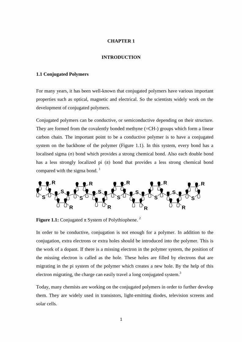
system on the backbone of the polymer (Figure 1.1). In this system, every bond has a
localised sigma (σ) bond which provides a strong chemical bond. Also each double bond
has a less strongly localized pi (π) bond that provides a less strong chemical bond
compared with the sigma bond. 1
SS
S
SS
SS
S
S
R
R
R
R
R
R
R
R
R
Figure 1.1: Conjugated π System of Polythiophene. 2
In order to be conductive, conjugation is not enough for a polymer. In addition to the
conjugation, extra electrons or extra holes should be introduced into the polymer. This is
the work of a dopant. If there is a missing electron in the polymer system, the position of
the missing electron is called as the hole. These holes are filled by electrons that are
migrating in the pi system of the polymer which creates a new hole. By the help of this
electron migrating, the charge can easily travel a long conjugated system.3
Today, many chemists are working on the conjugated polymers in order to further develop
them. They are widely used in transistors, light-emitting diodes, television screens and
solar cells.

2
Polyacetylene is the oldest impressive conjugated polymer. It was first discovered by
Natta and coworkers in 1958. 4 Natta and co-workers synthesized polyacetylene by the
polymerization of acetylene in hexane. They used Et3Al/Ti(OPr)4 (Et= ethyl, Pr=propyl)
as a catalyst. The resulting material was strongly crystalline with a regular structure. It
was a black, air-sensitive, infusible and insoluble powder. Ziegler-Natta polymerization
was discovered for the alkene polymerization like ethylene. In this polymerization, an
unsaturated molecule is inserted into the carbon-titanium bond of the growing
macromolecule.
Polyacetylene had a long conjugated backbone but it didn’t attract much interest in the
chemistry world. The important point was the discovery of polyacetylene films. They
were prepared by Shirakawa and co-workers from acetylene in 1974. 5 They used Ziegler-
natta catalyst for the synthesis of polyacetylene. However, the resulting polyacetylene
wasn’t a conductor. Figure 1.2 illustrates the all-cis and all-trans polyacetylene
synthesized by Shirakawa and co-workers.
all-cis-polyacetylene(copper colored)
all-trans-polyacetylene(silver colored)
Figure 1.2: All-cis and all-trans Polyacetylene. 5
The conductive polyacetylene films were discovered by Shirakawa, MacDiarmid and
Heeger in 1977. They showed that oxidation of the polyacetylene films by chlorine,
bromine or iodine vapor increases the conductivity of the polyacetylene films by 109
times
This treatment of the conjugated polymers via halogens was called as ‘doping’. The state
of the art of the conductivity of polymers was doping the polyacetylene which provides
the highest conductivity as 105 siemens/meter.
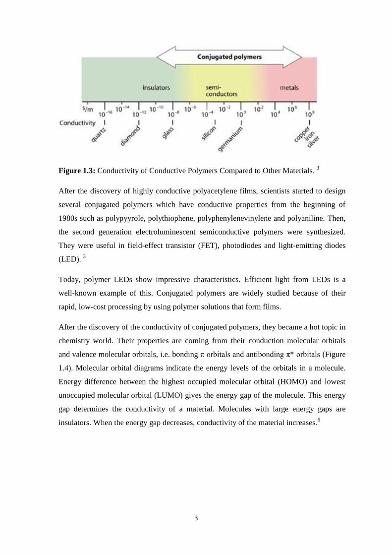
3 Figure 1.3 illustrates the conductivity of
conductive polymers compared to other materials.
3
Figure 1.3: Conductivity of Conductive Polymers Compared to Other Materials. 3
After the discovery of highly conductive polyacetylene films, scientists started to design
several conjugated polymers which have conductive properties from the beginning of
1980s such as polypyyrole, polythiophene, polyphenylenevinylene and polyaniline. Then,
the second generation electroluminescent semiconductive polymers were synthesized.
They were useful in field-effect transistor (FET), photodiodes and light-emitting diodes
(LED). 3
Today, polymer LEDs show impressive characteristics. Efficient light from LEDs is a
well-known example of this. Conjugated polymers are widely studied because of their
rapid, low-cost processing by using polymer solutions that form films.
After the discovery of the conductivity of conjugated polymers, they became a hot topic in
chemistry world. Their properties are coming from their conduction molecular orbitals
and valence molecular orbitals, i.e. bonding π orbitals and antibonding π* orbitals (Figure
1.4). Molecular orbital diagrams indicate the energy levels of the orbitals in a molecule.
Energy difference between the highest occupied molecular orbital (HOMO) and lowest
unoccupied molecular orbital (LUMO) gives the energy gap of the molecule. This energy
gap determines the conductivity of a material. Molecules with large energy gaps are
insulators. When the energy gap decreases, conductivity of the material increases.6

4
Figure 1.4: Idealized representation of energy bands and gaps. 7
Conjugated polymers have electroluminescent properties. Electroluminescence is an
optical and an electrical term which means the emission of light with the treatment of
electric current. The first report about the electroluminescent properties of the conjugated
polymers was published in 1990 by J.H.Burroughes and co-workers. 8 They used poly(p-
phenylene vinylene) PPV as a semiconducting polymer. Electroluminescent polymers are
widely used in light-emitting diodes. These diodes’ first layer containes a semiconductor
polymer. One side of the polymer is covered by a hole injection electrode, ITO (indium tin
oxide), and the other side is covered by an electron-injecting metal contact (i.e.
aluminium). By the application of a proper bias, electrons and holes are injected into the
system. Subsequently they meet at the polymer bulk film. After the radiative charge
carrier recombination in the semiconductive polymer film, emission of light is observed.
PPV has a 2.5eV energy band gap between its HOMO and LUMO level and produces a
yellow-green luminescence. Depending on the structure of the polymer, the energy band
gap varies and different emission color can be obtained. Figure 1.5 shows a general
example of the cross section of a polymer light-emitting diode.

5
Figure 1.5: A Cross Section of Polymer Light-emitting Diode. 3
1.1.1 Synthesis of Conjugated Polymers
After the discovery of the conductive polyacetylene, chemists started to develop various
organic semiconductive polymers which have a conjugated backbone. Many synthetic
procedures have been developed in this area. There are two main synthetic approaches for
conjugated polymers which are electrochemical synthesis and synthesis in solution.
1.1.1.1 Electrochemical Synthesis
Most of the conjugated polymers are synthesized via electrochemical polymerization.
Especially pyrrole and thiophene are synthesized by this method. In this method, the
monomer and the electrolyte are put in a suitable solvent such as acetonitrile and oxidized
at a mild potential such as 0.5. The oxidation (p-doping) is the halogen doping which
converts the polymer to a good conductor. At the anode, a polymer film starts to grow.
This reaction occurs in a heterogeneous environment which is the electrode surface. The
polymerization is occurred by the coupling of radical cations. 9
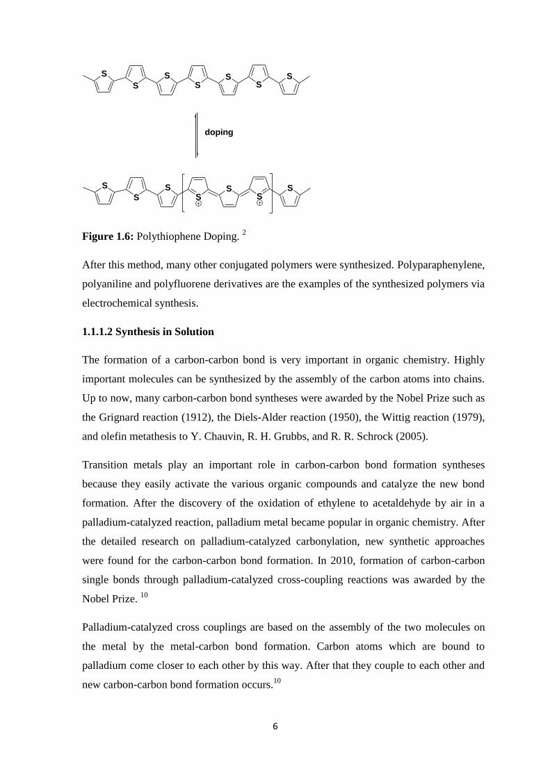
The prepared polymer film at the anode is doped by the excess charge which is passed in
the polymerization reaction and contains a counterion from the electrolyte solution (Figure
1.6). This film can be undoped by passing current from the reverse direction. 9
6
S
SS
SS
SS
doping
S
SS
SS
SS
Figure 1.6: Polythiophene Doping. 2
After this method, many other conjugated polymers were synthesized. Polyparaphenylene,
polyaniline and polyfluorene derivatives are the examples of the synthesized polymers via
electrochemical synthesis.
1.1.1.2 Synthesis in Solution
The formation of a carbon-carbon bond is very important in organic chemistry. Highly
important molecules can be synthesized by the assembly of the carbon atoms into chains.
Up to now, many carbon-carbon bond syntheses were awarded by the Nobel Prize such as
the Grignard reaction (1912), the Diels-Alder reaction (1950), the Wittig reaction (1979),
and olefin metathesis to Y. Chauvin, R. H. Grubbs, and R. R. Schrock (2005).
Transition metals play an important role in carbon-carbon bond formation syntheses
because they easily activate the various organic compounds and catalyze the new bond
formation. After the discovery of the oxidation of ethylene to acetaldehyde by air in a
palladium-catalyzed reaction, palladium metal became popular in organic chemistry. After
the detailed research on palladium-catalyzed carbonylation, new synthetic approaches
were found for the carbon-carbon bond formation. In 2010, formation of carbon-carbon
single bonds through palladium-catalyzed cross-coupling reactions was awarded by the
Nobel Prize. 10
Palladium-catalyzed cross couplings are based on the assembly of the two molecules on
the metal by the metal-carbon bond formation. Carbon atoms which are bound to
palladium come closer to each other by this way. After that they couple to each other and
new carbon-carbon bond formation occurs.10
7
Step-growth polymerization method is one of the most common method to synthesize
conjugated polymers. In this polymerization, bi-functional or multifunctional monomers
first react to form dimers, then trimers and at the end of the reaction long-chained
polymers. The most significant examples of the polymers synthesized via this way are
polyaniline, poly(phenylene sulfide), polythiophene and its derivatives.9
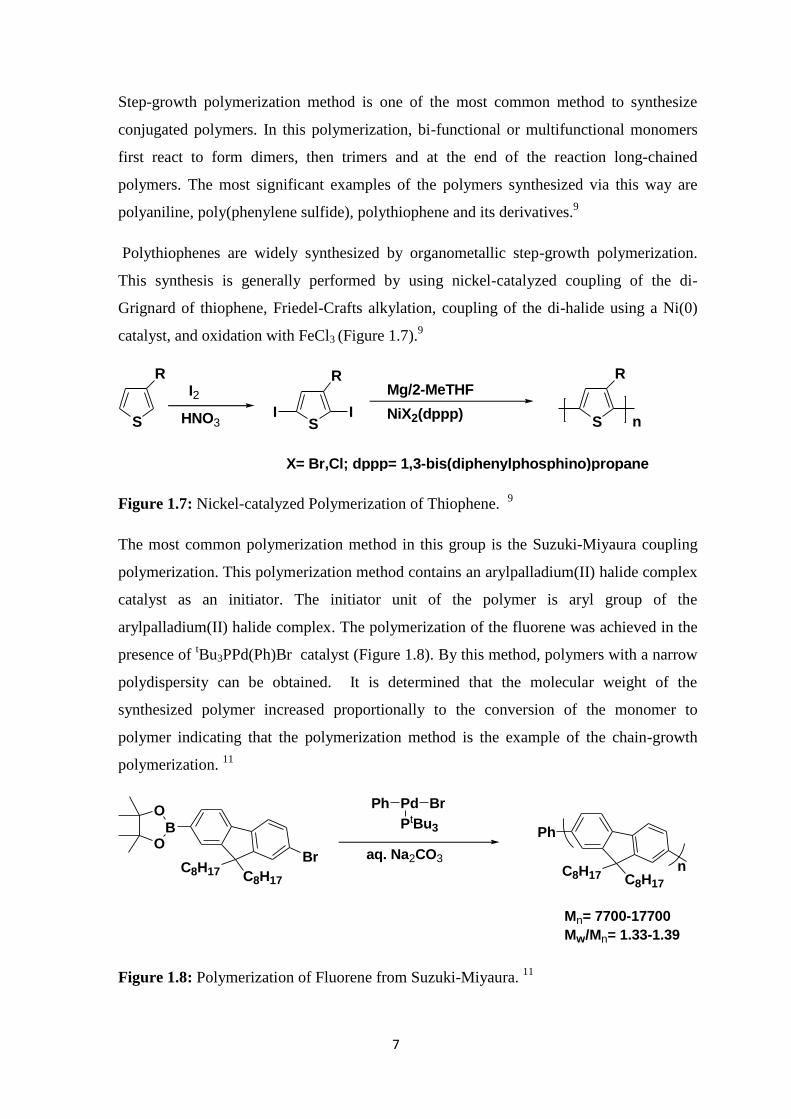
Polythiophenes are widely synthesized by organometallic step-growth polymerization.
This synthesis is generally performed by using nickel-catalyzed coupling of the di-
Grignard of thiophene, Friedel-Crafts alkylation, coupling of the di-halide using a Ni(0)
catalyst, and oxidation with FeCl3 (Figure 1.7).9
S
RI2
HNO3 S
R
I I
Mg/2-MeTHF
NiX2(dppp)S
R
n
X= Br,Cl; dppp= 1,3-bis(diphenylphosphino)propane
Figure 1.7: Nickel-catalyzed Polymerization of Thiophene. 9
The most common polymerization method in this group is the Suzuki-Miyaura coupling
polymerization. This polymerization method contains an arylpalladium(II) halide complex
catalyst as an initiator. The initiator unit of the polymer is aryl group of the
arylpalladium(II) halide complex. The polymerization of the fluorene was achieved in the
presence of tBu3PPd(Ph)Br catalyst (Figure 1.8). By this method, polymers with a narrow
polydispersity can be obtained. It is determined that the molecular weight of the
synthesized polymer increased proportionally to the conversion of the monomer to
polymer indicating that the polymerization method is the example of the chain-growth
polymerization. 11
B
BrC8H17 C8H17
O
O
PdPh Br
PtBu3
aq. Na2CO3
Ph
C8H17 C8H17
n
Mn= 7700-17700
Mw/Mn= 1.33-1.39
Figure 1.8: Polymerization of Fluorene from Suzuki-Miyaura. 11
8
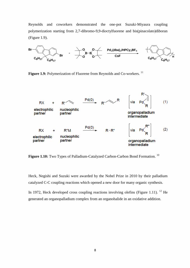
Reynolds and coworkers demonstrated the one-pot Suzuki-Miyaura coupling
polymerization starting from 2,7-dibromo-9,9-dioctylfuorene and bis(pinacolato)diboran
(Figure 1.9).
Br
BrC8H17 C8H17
OB
OB
O
O Pd2(dba)3/HPCy3BF4
CsFC8H17 C8H17
n
Figure 1.9: Polymerization of Fluorene from Reynolds and Co-workers. 11
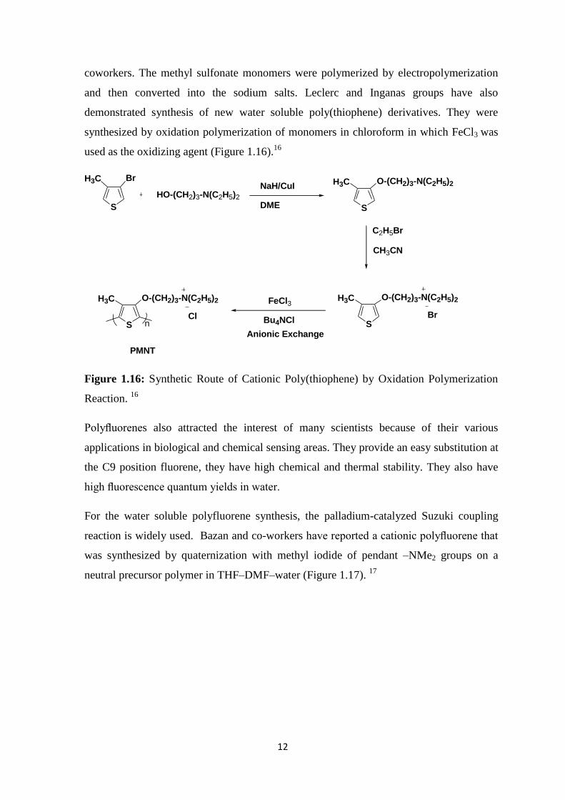
Figure 1.10: Two Types of Palladium-Catalyzed Carbon-Carbon Bond Formation. 10
Heck, Negishi and Suzuki were awarded by the Nobel Prize in 2010 by their palladium
catalyzed C-C coupling reactions which opened a new door for many organic synthesis.
In 1972, Heck developed cross coupling reactions involving olefins (Figure 1.11). 12
He
generated an organopalladium complex from an organohalide in an oxidative addition.

9
Figure 1.11: Mechanism of the Heck Reaction. 12
Reprinted with permission from ref. 12
(Copyright 2012 American Chemical Society)
In 1977, Negishi developed the organozinc compounds as the nucleophilic coupling
reagents in palladium-catalyzed cross coupling reactions (Figure 1.12). 13
Organozinc
compounds give very high yields when they are compared to the different organometallic
compounds. They are also highly mild and selective compounds. Organozinc compounds
allow for the presence of various functional groups in the palladium-catalyzed cross-
coupling reaction.
RZnY R'XPd-catalyst
R-R' MX
R, R' = aryl, vinyl, alkylX = halide, triflate, etc.
Figure 1.12: Negishi Reaction Scheme. 13
Reprinted with permission from ref. 13
(Copyright 2012 American Chemical Society)
In 1979, Suzuki and co-workers reported that organoboron compounds can easily be used
as coupling compounds if there is a base in the reaction medium in palladium-catalyzed
cross coupling reactions with vinyl and aryl halides (Figure 1.13). 14
Organoboron
reagents are activated by the base in the reaction medium that is resulted with a boronate

10
intermediates which provides the organic group transfer from boron to palladium. This
process is called as transmetallation. After the development of this reaction, coupling with
also alkyl groups were demonstrated.
R'XPd-catalyst
R-R' MX
R, R' = aryl, vinyl, alkylX = halide, triflate, etc.
RBY2base
Figure 1.13: Palladium-catalyzed Cross Coupling with Vinyl and Aryl Halide.14
In Suzuki cross-coupling reactions, an organoboron compound reacts with an
organohalide and forms a couple. Palladium(0) catalyzes these reactions. The reaction is
resulted with a new carbon-carbon bond formation (Figure 1.14).
Figure 1.14: Mechanism of the Suzuki Cross-coupling Reaction. 15
Reprinted with
permission from ref. 15 (Copyright 2012, Elsevier)
1.1.2 Properties and Applications of the Conjugated Polymers
Conjugated polymers have a wide range of applications. They are used in polymer-light
emitting devices, electroluminescent displays, field-effect transistors (FET), and in

11
various sensing devices.8 They are also widely used in supercapacitors. A high number of
conjugated polymers have electrochromic properties. These kind of polymers such as
polyaniline are used in smart windows which absorb sunlight.
1.1.3 Water soluble Conjugated Polymers
Water soluble conjugated polymers have a wide range of use in biological applications.
They are generally prepared by the incorporation of the water-soluble moieties. Water
soluble conjugated polymers are formed from the two parts. One part contains the
conjugated backbone which provides the good optical properties. Other part contains the
hydrophilic or charged functional groups such as ammonium, sulfonate which provides
polar groups for the solubility of the polymer in water (Figure 1.15). 16
, , orS
R = water-soluble moietiese.g. ammonium, sulfonate
Figure 1.15: Typical Structures of Water-soluble Conjugated Polymers. 16
Water soluble functional groups are generally charged. They provide the tunable
interactions between the conjugated polymers and the biomacromolecules. As a result of
the electrostatic interactions which provides the target recognition, scientists achieved a
lot of specific biological detections. Water soluble conjugated polymers have also wide
range of use in fluorescence imaging in vivo and in cell level. 16
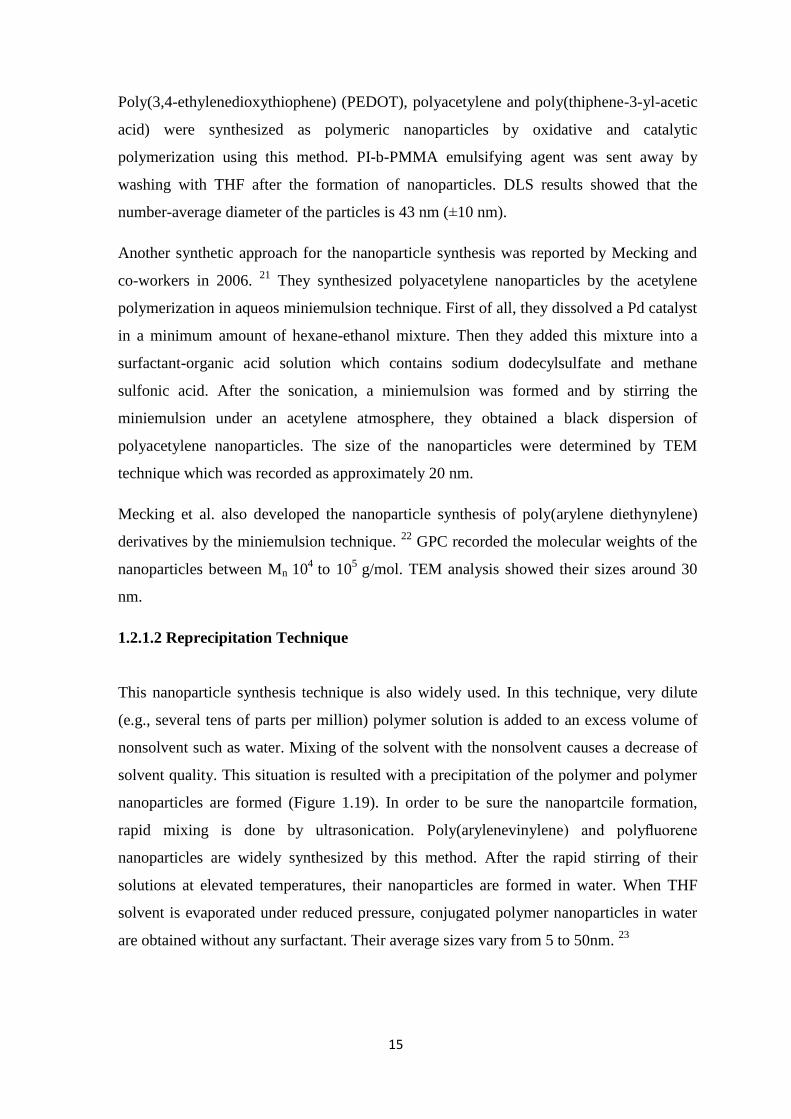
Poly(thiophene) (PT), poly(p-phenylenevinylene) (PPV), poly(p-phenyleneethynylene)
(PPE) and poly(fluorene) (PF) are widely used in fluorescent biosensing applications.
Poly(thiophene) is one of the oldest synthesized water-soluble polymer by Wudl and
:
R R R
12
coworkers. The methyl sulfonate monomers were polymerized by electropolymerization
and then converted into the sodium salts. Leclerc and Inganas groups have also
demonstrated synthesis of new water soluble poly(thiophene) derivatives. They were
synthesized by oxidation polymerization of monomers in chloroform in which FeCl3 was
used as the oxidizing agent (Figure 1.16).16
S
BrH3C
HO-(CH2)3-N(C2H5)2
NaH/CuI
DME S
H3C O-(CH2)3-N(C2H5)2
C2H5Br
CH3CN
S
H3C O-(CH2)3-N(C2H5)2
Br
FeCl3
Bu4NCl
Anionic ExchangeS
H3C O-(CH2)3-N(C2H5)2
Cl
PMNT
n
Figure 1.16: Synthetic Route of Cationic Poly(thiophene) by Oxidation Polymerization
Reaction. 16
Polyfluorenes also attracted the interest of many scientists because of their various
applications in biological and chemical sensing areas. They provide an easy substitution at
the C9 position fluorene, they have high chemical and thermal stability. They also have
high fluorescence quantum yields in water.
For the water soluble polyfluorene synthesis, the palladium-catalyzed Suzuki coupling
reaction is widely used. Bazan and co-workers have reported a cationic polyfluorene that
was synthesized by quaternization with methyl iodide of pendant –NMe2 groups on a
neutral precursor polymer in THF–DMF–water (Figure 1.17). 17

13
Br
Br
BrBr
KOH
n-Bu4NBr
Br
Br
Br
Br
B(OH)2(HO)2B
Pd(Ph3)42.0 M K2CO3
THF/water
Br
Br
n
Me3N
N
N
n
Br
Br
PFP-NBr
Figure 1.17: Synthesis of Cationic Polyfluorene. 17
1.2 Conjugated Polymer Nanoparticles
Conjugated polymer nanoparticles are highly versatile nanoparticles with their high
number of applications in various branches of chemistry. They provide important
opportunities in optoelectronics, photonics, bioimaging, biosensing and nanomedicine.
These nanoparticles have attracted the interest of the scientists for several reasons. First of
all, they have a straightforward synthetic route. Their properties can be easily tuned by
changing their structures which makes them easily modified for different applications.
They are also very advantageous in biological applications because of their low toxicity
and biocompatibility compared to the inorganic nanoparticles. 18
1.2.1 Preparation of the Conjugated Polymer Nanoparticles
Conjugated polymer nanoparticles are commonly synthesized via postpolymerization
dispersion technique. In this technique, polymer solutions dissolved in an organic solvent
is the beginning part. Nanoparticles are generally formed by the solvent removal from the

14
miniemulsion or by the addition of a polymer solution to an excess amount of continuous
phase which is resulted as a precipitation. 19
1.2.1.1 Miniemulsion Technique
This method is widely used in conjugated polymer nanoparticle synthesis. Here, the
polymer is dissolved in organic solvent which is not soluble in water. Then, the resulting
organic solution is injected into the water which contains an a suitable surfactant. The
mixture is stirred rapidly with the ultrasonication in order to form stable miniemulsions
which contains small polymer solution drops. Then, the organic solvent is evaporated and
resulting solution contains well-dispersed conjugated polymer nanoparticles (Figure 1.18).
It is easy to change the size of the nanoparticles by changing the concentration of the
nanoparticles. Their sizes vary from 30nm to 500nm18
.
Figure 1.18: Preparation of Nanoparticles by Miniemulsion Technique.
Ostwald ripening may cause the destabilization of the droplets by solvent diffusion
through the aqueous phase. In order to prevent this, hydrophobes are used. The
hydrophobe’s job is to promote the osmotic pressure formation inside the droplets. This
osmotic pressure counteracts the Laplace pressure which prevents the diffusion from one
of the polymer droplet to the aqueous medium around the droplets 18
.
Most of the examples of the conjugated polymer nanoparticle synthesis via miniemulsion
technique involve the synthesis of nanoparticles by using the polymers with an oil-in-
water system. In contrast to this system, Muller et al. developed the synthesis of
nanoparticles which started from the monomers in oil-in-oil emulsions. 20
They used
cyclohexane as a continuous phase and acetonitrile as a dispersed phase. Polyisoprene-
block-poly(methyl methacrylate) (PI-b-PMMA) was used as an emulsifying agent.
15
Poly(3,4-ethylenedioxythiophene) (PEDOT), polyacetylene and poly(thiphene-3-yl-acetic
acid) were synthesized as polymeric nanoparticles by oxidative and catalytic
polymerization using this method. PI-b-PMMA emulsifying agent was sent away by
washing with THF after the formation of nanoparticles. DLS results showed that the
number-average diameter of the particles is 43 nm (±10 nm).
Another synthetic approach for the nanoparticle synthesis was reported by Mecking and
co-workers in 2006. 21
They synthesized polyacetylene nanoparticles by the acetylene
polymerization in aqueos miniemulsion technique. First of all, they dissolved a Pd catalyst
in a minimum amount of hexane-ethanol mixture. Then they added this mixture into a
surfactant-organic acid solution which contains sodium dodecylsulfate and methane
sulfonic acid. After the sonication, a miniemulsion was formed and by stirring the
miniemulsion under an acetylene atmosphere, they obtained a black dispersion of
polyacetylene nanoparticles. The size of the nanoparticles were determined by TEM
technique which was recorded as approximately 20 nm.
Mecking et al. also developed the nanoparticle synthesis of poly(arylene diethynylene)
derivatives by the miniemulsion technique. 22
GPC recorded the molecular weights of the
nanoparticles between Mn 104
to 105
g/mol. TEM analysis showed their sizes around 30
nm.
1.2.1.2 Reprecipitation Technique
This nanoparticle synthesis technique is also widely used. In this technique, very dilute
(e.g., several tens of parts per million) polymer solution is added to an excess volume of
nonsolvent such as water. Mixing of the solvent with the nonsolvent causes a decrease of
solvent quality. This situation is resulted with a precipitation of the polymer and polymer
nanoparticles are formed (Figure 1.19). In order to be sure the nanopartcile formation,
rapid mixing is done by ultrasonication. Poly(arylenevinylene) and polyfluorene
nanoparticles are widely synthesized by this method. After the rapid stirring of their
solutions at elevated temperatures, their nanoparticles are formed in water. When THF
solvent is evaporated under reduced pressure, conjugated polymer nanoparticles in water
are obtained without any surfactant. Their average sizes vary from 5 to 50nm. 23

16
Figure 1.19: Preparation of the Nanoparticles by Reprecipitation Technique.
The nanoparticle size can be tuned easily by changing the concentration of the organic
polymer solution. In reprecipitation technique, colloidal stabilization of the nanoparticles
are not fully understood compared to the miniemulsion technique. In reprecipitation
technique, no surfactant is used and the polymer does not contain a hydrophilic moiety.
Charge accumulation at the particle-dispersing medium interface may be a one reason for
the stabilization toward particle aggregation and coalescence. Another reason for the steric
and electrostatic stabilization could be the impurities at low levels can adsorb to their
surface.19
The nanoparticles which are prepared by the reprecipitation technique are formed by the
overlap of the polymer chains which is resulted with a spherical-shaped nanoparticles.
They are thermodynamically favorable.
In the reprecipitation technique case, Moon et al. reported the synthesis of nanoparticles
from poly-(phenylene ethynylene) (PPE) derivatives by phase inversion precipitation
(Figure 1.20). 24
According to the report, polymer is dissolved in DMSO and then added
into the aqueous SSPE buffer (saline, sodium phosphate, EDTA). According to the DLS
measurements, a mean particle size is 400–500 nm.

17
n
O
O
NH2
O
O
O
O
O
O
O
O
O
O
H2N
PPE-2
Figure 1.20: Structures of Poly(phenylene ethynylene) (PPE) Derivative Used in
Nanoparticle Synthesis. 24
Nanoparticles are mainly formed by the hydrophobic effect. When the organic polymer
solution is poured into water, polymer chains do not want to contact with water. As a
result, they gain spherical shapes in order to decrease the interaction with water. So, the
amount of the hydrophilic side groups significantly affects the nanoparticle formation. If
the side chain contains the protonated amine group and the short chain contains the
nonionic diethylene oxide group, aggregation and precipitation is prevented by the
stabilization of the nanoparticle surface.18
1.2.2 Properties and Applications of the Conjugated Polymer Nanoparticles
Photophysical properties of nanoparticles make them very desirable materials for many
applications. One of the most important applications of these nanoparticles is in
optoelectronics.
Before using the CPNs in the fabrication of optoelectronics, it should be known if the
photophysical and optical properties of the polymers affect the nanoparticle formation. In
addition, in the miniemulsion technique of the nanoparticles synthesis, some surfactants
and hydrophobes are used. It is very important to determine the influence of these
surfactants and hydrophobes on the photophysical properties of the nanoparticles. CPNs.
19

18
In order to demonstrate the photophysical properties of CPNs which are synthesized via
the miniemulsion technique, Piok et al. studied on the methyl-substituted ladder-type
poly(para-phenylene) (m-LPPP). 25
They worked on the nonequilibrium photoexcitation
dynamics of CPNs and then compared them with the same polymer’s film. According to
results, synthesis of nanoparticles from m-LPPP isn’t resulted with a significant change in
the optical properties of the polymer. Absorption and emission spectra are not change
again with the change of size.
Photophysical properties of nanoparticles synthesized by the reprecipitation method was
also studied. Masuhara and co-workers synthesized nanoparticles from poly(3-[2-(N-
dodecylcarbamoyloxy)ethyl]thiophene-2,5-diyl) (P3DDUT) with different sizes changing
from 40 nm to 400 nm. 26
They controlled the spectroscopic and thermochromic behavior
of the nanoparticles in water. They also made films from their water dispersions. In the
absorption and emission spectra, a blue shift was observed.
In the applications related to the energy transfers, conjugated polymer nanoparticles are
highly used again. Fluorescence energy transfer has many applications in molecular
biosensors and optoelectronic devices. In order to observe a FRET, excitation energy of
the fluorophore which acts as a donor should be transferred to the fluorophore that acts
as an acceptor which follows a nonradiative pathway. Energy transfer is widely used in
conjugated polymers in order to increase the quantum efficiency and change the emission
color of LEDs. 27
DNA and protein sensing are also well-known examples of FRET
applications.
Grigalevicius and co-workers synthesized the first dye-doped conjugated polymer
nanoparticles in 2006. 28
Energy transfer from the excited nanoparticle chromophore to the
fluorescent dye was shown. They have synthesized nanoparticles with negative charges
from blue-emitting polyfluorene derivatives. They used the anionic surfactant sodium
dodecyl sulfate. They incorporated Rhodamine 6G and tetramethylrhodamine ethyl ester
perchlorate (Rhodamine TM) as cationic fluorescent dyes. Results showed that intensity
of the blue fluorescence of the dye-coated polyfluorene nanoparticles decreased after they
were doped with the dyes. After the energy transfer, emission band of the dye (Rhodamine
6G or Rhodamine TM) which is bound to surface is observed between the 530 nm and
600 nm. This results indicates that excitation energy from PF chromophores was
transferred successfully to the fluorescent dye.
19
Conjugated polymer nanoparticles are also widely used in the biological sensor
applications. In these systems, water soluble materials are required. For this aim, Moon
and co-workers synthesized CPNs from PPE that contains amine groups via ultrafiltration.
29 They showed the usage of CPNs for 2P imaging of endothelial cells in a tissue model.
2P-action cross section of CPNs were measured between 1000-11000 GM. The maximum
value was about 730 nm. This value is significantly higher than the recent organic
fluorophores and very close to the quantum dots (QDs).
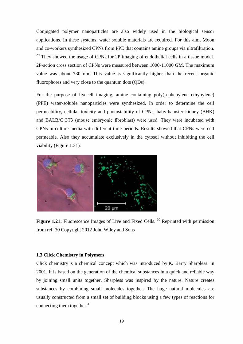
For the purpose of livecell imaging, amine containing poly(p-phenylene ethynylene)
(PPE) water-soluble nanoparticles were synthesized. In order to determine the cell
permeability, cellular toxicity and photostability of CPNs, baby-hamster kidney (BHK)
and BALB/C 3T3 (mouse embryonic fibroblast) were used. They were incubated with
CPNs in culture media with different time periods. Results showed that CPNs were cell
permeable. Also they accumulate exclusively in the cytosol without inhibiting the cell
viability (Figure 1.21).
Figure 1.21: Fluorescence Images of Live and Fixed Cells. 30
Reprinted with permission
from ref. 30 Copyright 2012 John Wiley and Sons
1.3 Click Chemistry in Polymers
Click chemistry is a chemical concept which was introduced by K. Barry Sharpless in
2001. It is based on the generation of the chemical substances in a quick and reliable way
by joining small units together. Sharpless was inspired by the nature. Nature creates
substances by combining small molecules together. The huge natural molecules are
usually constructed from a small set of building blocks using a few types of reactions for
connecting them together.31

20
One of the most important part of the click chemistry is the cycloaddition reactions which
involve the heteroatoms. Hetero-Diels-Alder reaction is an example of this cycloaddition
reaction. The most significant reaction is 1,3-dipolar cycloadditions (Figure 1.22). These
cycloaddition reactions need two unsaturated reactants and they provide various five- and
six-membered heterocycles. In these click reactions, Huisgen dipolar cycloaddition of
azides and alkynes play an important role. This reaction occurs between C–C triple, C–N
triple bonds and alkyl-/aryl-/sulfonyl azides. The products are tetrazoles, 1,2,3-triazoles
and 1,2-oxazoles, respectively.32
HR
N N NR'
Cu(I), Ru
Pd2+, Pt2+, Ni2+
N N
NR R'
N
NN
R
R'
1,4-adduct (preferred)
1,5-adduct
or
Figure 1.22: Azide-alkyne Click Reaction. 32
The reaction mechanism was determined by computational methods and demonstrated by
Bock et al (Figure 1.23).
Figure 1.23: Azide-alkyne Click Reaction Mechanism. 32
Reprinted with permission from
ref. 32 Copyright 2012, John Wiley and Sons

21
Click Chemistry is also widely used in polymer reactions and polymeric applications. Its
reaction efficiency is quite high and has a high functional group tolerance. This reaction is
very active in water which makes it an important reaction in biological studies. Click
chemistry concept demonstrates a solution to a lot of problems related to the polymer
science. First of them is the poor degree of functionalization with many well-known
techniques. If the polymer involves multiple functional groups (i.e.: at graft-, star-, and
block copolymers, dendrimers, as well as on densely packed surfaces and interfaces), this
becomes a much more serious problem. Second problem is the purification problems
related with the often emerging partially functionalized mixtures. Harsh reaction
conditions of conventional methods are also a big problem that can be overcome by click
chemistry.
The click chemistry opens a new door to a various researches related to the new
functionalized polymeric architectures, hitherto unreachable by the polymerization
methods themselves. Cu-catalyzed azide-alkyne coupling reaction provides a small-
molecule organic chemistry in polymer science. It brings the functional broadness,
molecular addressability, and structural integrity. 33
1.4 Crosslinked Polymer Nanoparticles via Click Chemistry
Cu(I)-catalyzed azide-alkyne coupling (CuAAC) is very popular in nanochemistry. It has
various applications in nanoscale studies. A lot of research groups have utilized CuAAC
for the biological, polymeric, inorganic and carbon nanoscale objects. Wooley and
coworkers have studied on the synthesis of shell and core crosslinked polymeric
nanoparticles (Figure 1.24). 34,
35
They were synthesized from amphiphilic PS–PAA
diblock copolymers. Mentioned copolymers contain alkyne groups on the hydrophilic
PAA block for shell crosslinked nanoparticles or the hydrophobic PS block for core
crosslinked nanoparticles. They had a micelle-like shapes in water and were crosslinked
by CuAAC by reacting with bifunctional azide groups and multifunctional dendritic
azides. The reaction was resulted with the formation of the polymeric nanoparticles. After
the formation of the nanoparticles, they were further functionalized with fluorescent
groups.

22
Figure 1.24: Molecular Structure of Shell-CuAAC-crosslinked Polymeric Nanoparticles
Prepared by Wooley and Co-workers. 34
Reprinted with permission from ref. 34 Copyright
2012 American Chemical Society
Finn and coworkers have demonstrated the synthesis of a highly crosslinked polymer by
using tripropargyl amine and 1,6-diazidohexane in a solution phase CuAAC reaction
(Figure 1.25). 36
Polymer synthesized by Finn and coworkers was swelling and deswelling reversibly
when it was mixed with trifluoroacetic acid (Figure 1.25). This observation was the result
of the amine functional groups in the polymer.
Figure 1.25: Acid-swellable CuAAC-crosslinked Network. 36
Reprinted with permission
from ref. 36 Copyright 2012, John Wiley and Sons
Liu and coworkers have followed a similar approach with the synthesis of core
crosslinked nanoparticles comprised of poly(N,N-dimethylacrylamide) (PDMA) and

23
poly(N-isopropylacrylamide-co-azidopropylacrylamide). 37
Caruso and coworkers
demonstrated an attractive synthesis of highly thin microcapsules via facile layer-by-layer
(LBL)/CuAAC approach. 38
First of all, the authors used the electrostatic and hydrogen
bonding interactions between PAA and silica to deposit a thin layer of PAA. Some of its
carboxylic acid units were converted to azides (PAA-N3), onto the silica particle. After
that, PAA layers containing alkynes (PAA-alkyne) were coated to the previous layer via
CuAAC. Mentioned process was repeated several times in order to make the yield
desirable.
Click chemistry is also widely used for biodegradable polymer nanoparticles. As it is all
known that the triazole group formed by azide–alkyne cycloaddition reaction has
significant chemical stability. However, biodegradable NPs can be obtained when
biodegradable polymers are used for crosslinking. As demonstrated by Harth and
coworkers, using biodegradable polyesters as precursors, discrete functionalized NPs have
been obtained via a controlled intermolecular click crosslinking process 39
1.5 Aim of the Thesis
In this study, a novel method was demonstrated for the synthesis of water-dispersible
conjugated polymer nanoparticles with enhanced stability. Fluorene and thiophene-based
conjugated polymer nanoparticles were synthesized that can be used in biological
applications such as cell imaging and drug delivery.
For cell imaging and drug delivery, conjugated polymer nanoparticles attracted much
interest in chemistry, biology and medicine world. In this study, the aim is to synthesize
water-dispersible, multifunctional and stable conjugated polymer nanoparticles and
contribute to the biological studies with a new aspect.
Crosslinked conjugated polymer nanoparticles were synthesized by 1,3-dipolar
cycloaddition reaction between an azide group and a diaminodialkyne crosslinker. By this
crosslinking, various useful functional groups were introduced to the nanoparticles such
as triazole and amine groups. This provides the formation of water-dispersible
nanoparticles which is desired for cell imaging and biomolecule delivery studies.

24
In 1,3-dipolar cycloaddition reaction, Cu(I) and cucurbituril (CB6) were used as a
catalyst. The idea of using CB6 as a catalyst was to get more biocompatible nanoparticles
for biological applications. It also provided rotaxane structures in the nanoparticles.
Crosslinking of the conjugated polymer nanoparticles was also achieved by the
irradiation of the nanoparticles under UV light. All CPNs synthesized with different
crosslinking techniques were designed as novel candidates of biomolecule delivery
agents and cell imaging.

25
CHAPTER 2
RESULTS AND DISCUSSION
This chapter is divided into three main parts. In the first part, synthesis and characterization of
the monomers as a precursor of the polymers are discussed. In the second part, synthesis and
various characterization techniques of the facile polymers are demonstrated. In the final part,
preparation and fully characterization of the water-dispersible crosslinked polymer
nanoparticles are explained in detail.
This project demonstrates a novel synthetic method for the synthesis of water-dispersible
conjugated polymer nanoparticles with enhanced chemical and mechanical stability. Synthesis
of the polymers and their nanoparticle preparation via reprecipitation technique were studied
in detail. The synthesized nanoparticles in this project can be utilized for biological studies
such as cell imaging, drug delivery in biological system and theranostic nanomedicine. This
project opens an important door for the conjugated polymer nanoparticle synthesis and
applications.

26
2.1 Synthesis and Characterization of Monomers
2.1.1 Synthesis and Characterization of 2-(2,5-dibromothiophen-3-yl)ethanol (M1)
2-(2,5-dibromothiophen-3-yl)ethanol (M1) was synthesized by the bromination of alpha
positions of thiophene with N-bromosuccinimide (NBS). After the reaction at 40 oC under
N2, product was extracted with diethylether and purified by column chromatography by
using hexane with the yield of 64%.
The synthesis of the monomer M1 was illustrated in Scheme 2.1.
S
OH
S
OH
BrBr
NBS, DMF
40 oC, 12 h under N2
Scheme 2.1: Synthesis of the monomer 2-(2,5-dibromothiophen-3-yl)ethanol (M1)
demonstrates the bromination with NBS at 40 oC for 12 h under N2.
Monomer M1 was characterized by 1H-NMR spectroscopy. Figure 2.1 shows the
1H-
NMR spectrum of monomer M1.
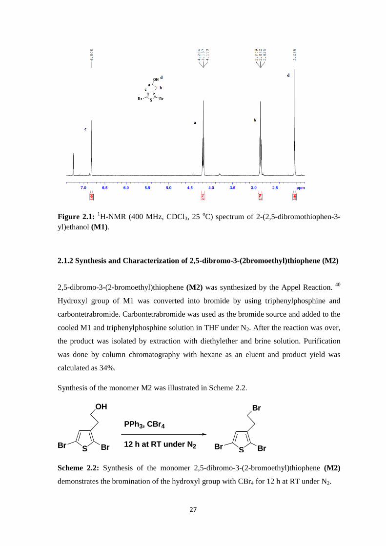
According to the 1H-NMR spectrum, triplets at 4.19 ppm and 2.84 ppm labeled as (a) and
(b) belong to the –CH2 protons nearer to the hydroxyl group and thiophene, respectively. –
CH2 protons nearer to the hydroxyl group were deshielded because of the electronegative
hydroxyl group. A sharp singlet at 2.04 ppm is coming from the proton of hydroxyl group.
The proton at the beta position of thiophene was detected as a singlet at 6.81 ppm.
27
Figure 2.1: 1H-NMR (400 MHz, CDCl3, 25
oC) spectrum of 2-(2,5-dibromothiophen-3-
yl)ethanol (M1).
2.1.2 Synthesis and Characterization of 2,5-dibromo-3-(2bromoethyl)thiophene (M2)
2,5-dibromo-3-(2-bromoethyl)thiophene (M2) was synthesized by the Appel Reaction. 40
Hydroxyl group of M1 was converted into bromide by using triphenylphosphine and
carbontetrabromide. Carbontetrabromide was used as the bromide source and added to the
cooled M1 and triphenylphosphine solution in THF under N2. After the reaction was over,
the product was isolated by extraction with diethylether and brine solution. Purification
was done by column chromatography with hexane as an eluent and product yield was
calculated as 34%.
Synthesis of the monomer M2 was illustrated in Scheme 2.2.
S
OH
BrBrS
Br
BrBr
PPh3, CBr4
12 h at RT under N2
Scheme 2.2: Synthesis of the monomer 2,5-dibromo-3-(2-bromoethyl)thiophene (M2)
demonstrates the bromination of the hydroxyl group with CBr4 for 12 h at RT under N2.
28
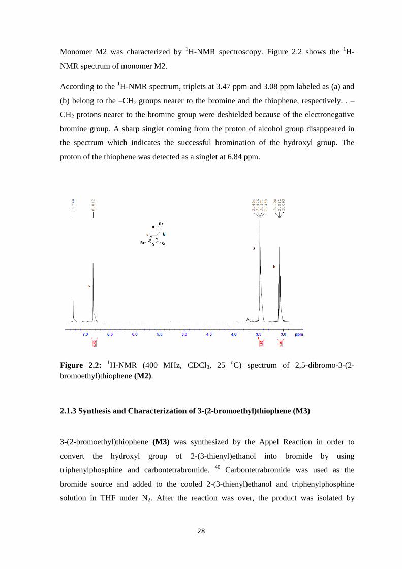
Monomer M2 was characterized by 1H-NMR spectroscopy. Figure 2.2 shows the
1H-
NMR spectrum of monomer M2.
According to the 1H-NMR spectrum, triplets at 3.47 ppm and 3.08 ppm labeled as (a) and
(b) belong to the –CH2 groups nearer to the bromine and the thiophene, respectively. . –
CH2 protons nearer to the bromine group were deshielded because of the electronegative
bromine group. A sharp singlet coming from the proton of alcohol group disappeared in
the spectrum which indicates the successful bromination of the hydroxyl group. The
proton of the thiophene was detected as a singlet at 6.84 ppm.
Figure 2.2: 1H-NMR (400 MHz, CDCl3, 25
oC) spectrum of 2,5-dibromo-3-(2-
bromoethyl)thiophene (M2).
2.1.3 Synthesis and Characterization of 3-(2-bromoethyl)thiophene (M3)
3-(2-bromoethyl)thiophene (M3) was synthesized by the Appel Reaction in order to
convert the hydroxyl group of 2-(3-thienyl)ethanol into bromide by using
triphenylphosphine and carbontetrabromide. 40
Carbontetrabromide was used as the
bromide source and added to the cooled 2-(3-thienyl)ethanol and triphenylphosphine
solution in THF under N2. After the reaction was over, the product was isolated by

29
extraction with diethylether and brine solution. Purification was done by column
chromatography with hexane as an eluent and the product yield was calculated as 79%.
This monomer was synthesized as a precursor of the trimethyl amine functionalized
polymer P4 which was synthesized via oxidative polymerization. For this reason, the
hydroxyl group of the 2-(3-thienyl)ethanol was brominated by the Appel Reaction without
bromination of the alpha positions of thiophene.
Synthesis of the monomer M3 was illustrated in Scheme 2.3.
S
OH
S
Br
PPh3, CBr4
12 h at RT under N2
Scheme 2.3: Synthesis of the monomer 3-(2-bromoethyl)thiophene (M3) demonstrates
the bromination of the hydroxyl group with CBr4 for 12 h at RT under N2.
Monomer M3 was characterized by 1H-NMR spectroscopy. Figure 2.3 shows the
1H-
NMR spectrum of monomer M3.
According to the 1H-NMR spectrum, triplets at 3.55 ppm and 3.19 ppm labeled as (a) and
(b) belong to the –CH2 groups nearer to the bromine group and the thiophene,
respectively. A sharp singlet coming from the proton of hydroxyl group disappeared in the
spectrum which indicates the successful bromination of the alcohol. Aromatic protons of
thiophene labeled as (c), (d) and (e) were coming at 7.27 ppm, 7.05 ppm and 6.96 ppm as
multiplets and doublet of doublets, respectively.

30
Figure 2.3: 1H-NMR (400 MHz, CDCl3, 25
oC) spectrum of 3-(2-bromoethyl)thiophene
(M3).
2.1.4 Synthesis and Characterization of 2-(thiophen-3-yl)-N,N,N
trimethylethanammonuimbromide (M4)
2-(thiophen-3-yl)-N,N,N trimethylethanammoniumbromide (M4) was synthesized by the
nucleophilic substitution reaction between the trimethylamine and the bromine group of 3-
(2-bromoethyl)thiophene. 40
3-(2-bromoethyl)thiophene (M3) was dissolved in a
minimum amount of THF and added to 25% trimethylamine solution. After 4 days
stirring, the excess trimethylamine solution was evaporated and the product was purified
by hexane:acetone washing with the yield of 59%.
Synthesis of the monomer M4 was illustrated in Scheme 2.4.
S
Br
S
N Br
NMet3, THF
4 days at RT
Scheme 2.4: Synthesis of the monomer 2-(thiophen-3-yl)-N,N,N
trimethylethanammoniumbromide (M4) demonstrates the amination of the bromine group
with NMet3 at RT.
31
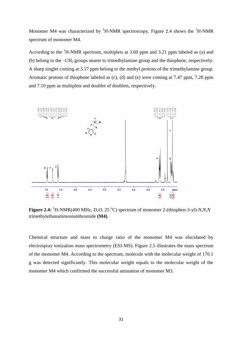
Monomer M4 was characterized by 1H-NMR spectroscopy. Figure 2.4 shows the
1H-NMR
spectrum of monomer M4.
According to the 1H-NMR spectrum, multiplets at 3.60 ppm and 3.21 ppm labeled as (a) and
(b) belong to the –CH2 groups nearer to trimethylamine group and the thiophene, respectively.
A sharp singlet coming at 3.17 ppm belong to the methyl protons of the trimethylamine group.
Aromatic protons of thiophene labeled as (c), (d) and (e) were coming at 7.47 ppm, 7.28 ppm
and 7.10 ppm as multiplets and doublet of doublets, respectively.
Figure 2.4: 1H-NMR(400 MHz, D2O, 25
oC) spectrum of monomer 2-(thiophen-3-yl)-N,N,N
trimethylethanammoniumbromide (M4).
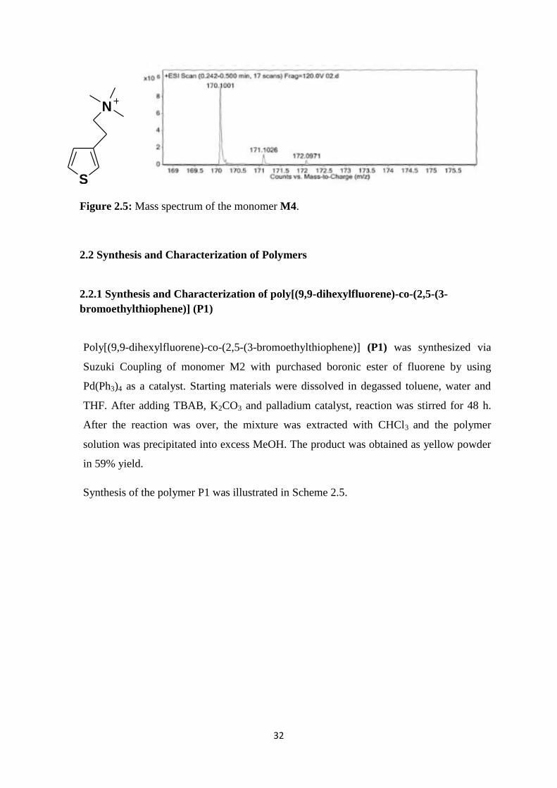
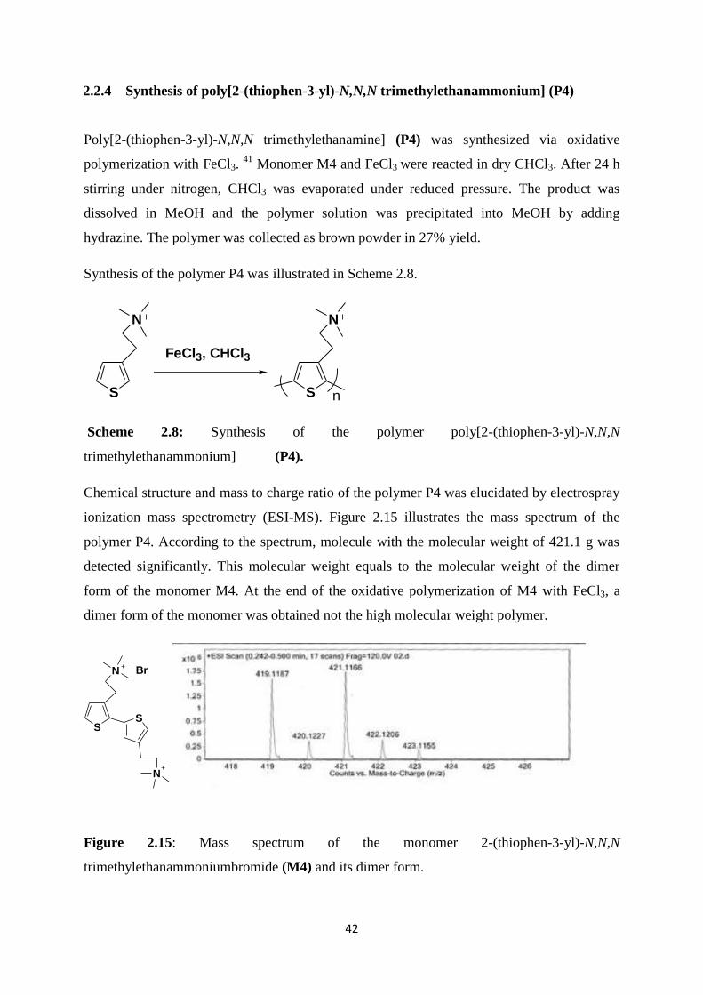
Chemical structure and mass to charge ratio of the monomer M4 was elucidated by
electrospray ionization mass spectrometry (ESI-MS). Figure 2.5 illustrates the mass spectrum
of the monomer M4. According to the spectrum, molecule with the molecular weight of 170.1
g was detected significantly. This molecular weight equals to the molecular weight of the
monomer M4 which confirmed the successful amination of monomer M3.
32
S
N
Figure 2.5: Mass spectrum of the monomer M4.
2.2 Synthesis and Characterization of Polymers
2.2.1 Synthesis and Characterization of poly[(9,9-dihexylfluorene)-co-(2,5-(3-
bromoethylthiophene)] (P1)
Poly[(9,9-dihexylfluorene)-co-(2,5-(3-bromoethylthiophene)] (P1) was synthesized via
Suzuki Coupling of monomer M2 with purchased boronic ester of fluorene by using
Pd(Ph3)4 as a catalyst. Starting materials were dissolved in degassed toluene, water and
THF. After adding TBAB, K2CO3 and palladium catalyst, reaction was stirred for 48 h.
After the reaction was over, the mixture was extracted with CHCl3 and the polymer
solution was precipitated into excess MeOH. The product was obtained as yellow powder
in 59% yield.
Synthesis of the polymer P1 was illustrated in Scheme 2.5.
33
S
Br
BrBr
B
B
O
O
O
O
S
Br
n
Pd(Ph3)4, K2CO3, TBAB
Toluene, THF, H2O
80oC, 48 h
Scheme 2.5: Synthesis of polymer poly[(9,9-dihexylfluorene)-co-(2,5-(3-
bromoethylthiophene)] (P1) via Suzuki coupling with Pd(Ph3)4 catalyst.
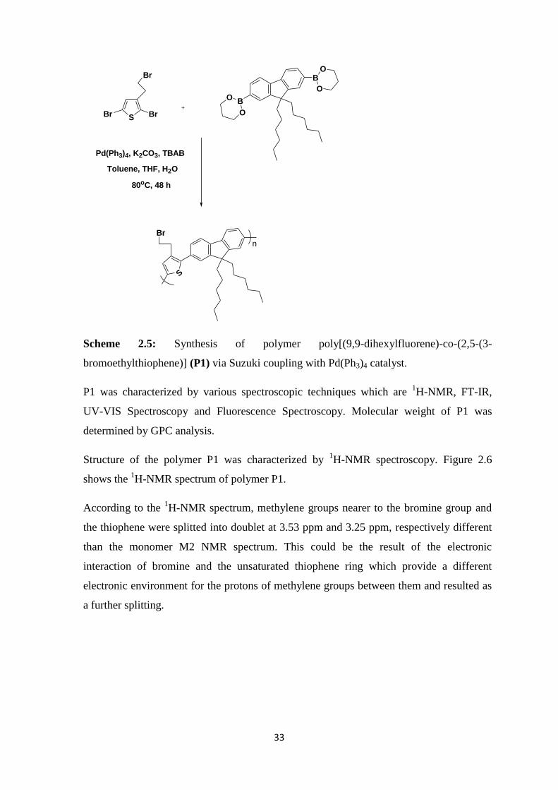
P1 was characterized by various spectroscopic techniques which are 1H-NMR, FT-IR,
UV-VIS Spectroscopy and Fluorescence Spectroscopy. Molecular weight of P1 was
determined by GPC analysis.
Structure of the polymer P1 was characterized by 1H-NMR spectroscopy. Figure 2.6
shows the 1H-NMR spectrum of polymer P1.
According to the 1H-NMR spectrum, methylene groups nearer to the bromine group and
the thiophene were splitted into doublet at 3.53 ppm and 3.25 ppm, respectively different
than the monomer M2 NMR spectrum. This could be the result of the electronic
interaction of bromine and the unsaturated thiophene ring which provide a different
electronic environment for the protons of methylene groups between them and resulted as
a further splitting.

34
Figure 2.6: 1H-NMR (400 MHz, CDCl3, 25
oC) spectrum of poly[(9,9-dihexylfluorene)-
co-(2,5-(3-bromoethylthiophene)] (P1).
Structure of P1 was also characterized by FT-IR spectroscopy. Figure 2.7 shows the FT-
IR spectrum of polymer P1.
According to the FT-IR spectrum, alkyl chain strechings of 9,9-dihexylfluorene were
observed at around 2928 cm-1
. A strong peak at 1464 cm-1
was seen because of the C-C
stretching of the aromatic fluorene backbone of the polymer. C-Br stretching was
observed at 818 cm-1
.
Figure 2.7: FT-IR (KBr pellet, cm-1
) spectrum of polymer poly[(9,9-dihexylfluorene)-co-
(2,5-(3-bromoethylthiophene] (P1).

35
The optical properties of P1 were determined by UV-Vis and fluorescence spectroscopy
(Figure 2.8). Absorption spectrum of P1 was obtained by dissolving P1 in THF.
Absorption maxima was observed at 383 nm. Emission intensity of P1 was determined by
fluorescence spectroscopy. P1 was dissolved in THF and emission spectrum was obtained.
The emission maxima of P1 was observed at 471 nm.
Figure 2.8: Absorption and emission spectra of polymer poly[(9,9-dihexylfluorene)-co-
(2,5-(3-bromoethylthiophene] (P1) in THF (λabs = 383 nm, λexc = 383 nm, λem = 471
nm).
2.2.2 Synthesis and Characterization of poly[(9,9-dihexylfluorene)-co-(2,5-(3-
azidoethylthiophene)] (P2)
Poly[(9,9-dihexylfluorene)-co-(2,5-(3-azidoethylthiophene)] (P2) was synthesized via
conversion of –Br groups of P1 into azide groups by nucleophilic substitution reaction
with sodium azide in DMF. After the reaction at 90 oC, solvent was evaporated and the
desired product was dissolved in THF and precipitated into water; yellow powders were
obtained. The yield of the reaction was 87%.
The reaction scheme 2.6 illustrates the synthesis of polymer P2.
383 nm 471 nm

36
S
Br
n
S
N3
n
NaN3, DMF
90 oC under N2
Scheme 2.6: Synthesis of polymer poly[(9,9-dihexylfluorene)-co-(2,5-(3-
azidoethylthiophene)] (P2) by the functionalization of the polymer P1 with NaN3.
P2 was characterized by various spectroscopic techniques which are 1H-NMR, FT-IR,
UV-Vis and fluorescence spectroscopy. Molecular weight of P2 was determined by
GPC analysis.
Structure of the polymer P2 was determined by 1H-NMR spectroscopy. Figure 2.9
shows the 1H-NMR spectrum of polymer P2.
According to the 1H-NMR spectrum, methylene peaks at the secondary position of the
azide group were shifted 0.2 ppm to upfield . This could be due to the location of the
methylene protons nearer to the thiophene which is in the anisotropic cone of the azide
group. These methylenic protons are located in the cone-shaped shielding zone of the
azide group and shifted to the upfield.

37
Figure 2.9: 1H-NMR (400 MHz, CDCl3, 25
oC) spectrum of poly[(9,9-dihexylfluorene)-
co-(2,5-(3-azidoethylthiophene)] (P2).
Figure 2.10 shows the superposed NMR spectra of the polymer P1 and P2.
Figure 2.10: 1H-NMR spectra of the polymer P1 and P2.
38
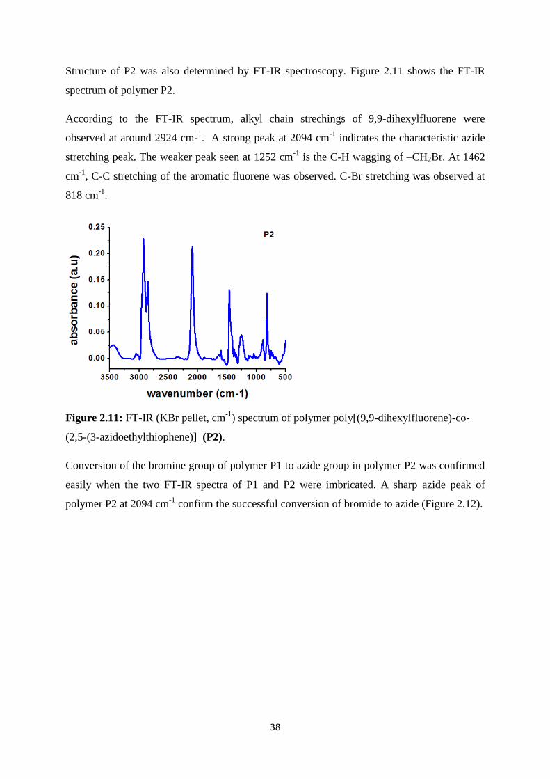
Structure of P2 was also determined by FT-IR spectroscopy. Figure 2.11 shows the FT-IR
spectrum of polymer P2.
According to the FT-IR spectrum, alkyl chain strechings of 9,9-dihexylfluorene were
observed at around 2924 cm-1. A strong peak at 2094 cm
-1 indicates the characteristic azide
stretching peak. The weaker peak seen at 1252 cm-1
is the C-H wagging of –CH2Br. At 1462
cm-1
, C-C stretching of the aromatic fluorene was observed. C-Br stretching was observed at
818 cm-1
.
Figure 2.11: FT-IR (KBr pellet, cm-1
) spectrum of polymer poly[(9,9-dihexylfluorene)-co-
(2,5-(3-azidoethylthiophene)] (P2).
Conversion of the bromine group of polymer P1 to azide group in polymer P2 was confirmed
easily when the two FT-IR spectra of P1 and P2 were imbricated. A sharp azide peak of
polymer P2 at 2094 cm-1
confirm the successful conversion of bromide to azide (Figure 2.12).

39
Figure 2.12: Confirmation of the successful functionalization of polymer poly[(9,9-
dihexylfluorene)-co-(2,5-(3-bromoethylthiophene] (P1) to polymer polymer poly[(9,9-
dihexylfluorene)-co-(2,5-(3-azidoethylthiophene)] (P2) by the FT-IR (KBr pellet, cm-1
)
spectra of the polymers.
Optical properties of P2 were determined by UV-Vis and fluorescence spectroscopy.
Absorption maxima of P2 was observed at 383 nm. Emission intensity of P2 was determined
by fluorescence spectroscopy and emission maxima was observed at 457 nm (Figure 2.13).
Figure 2.13: Absorption and emission spectra of polymer poly[(9,9-dihexylfluorene)-co-(2,5-
(3-azidoethylthiophene)] (P2) in THF (λabs = 383 nm, λexc = 383 nm, λem = 457 nm).
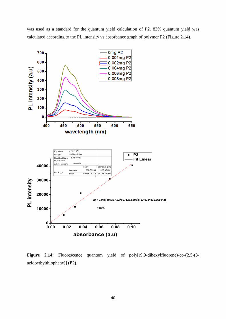
The fluorescence quantum yield of polymer P2 was calculated in order to determine the
emission efficiency of the conjugated polymer. All measurements were done in THF. P2 is a
green fluorescent polymer and fluorescein in ethanol (λabs = 484 nm, λem = 520 nm, Q = 97%)
N3 streching
383 nm 457 nm
40
was used as a standard for the quantum yield calculation of P2. 83% quantum yield was
calculated according to the PL intensity vs absorbance graph of polymer P2 (Figure 2.14).
Figure 2.14: Fluorescence quantum yield of poly[(9,9-dihexylfluorene)-co-(2,5-(3-
azidoethylthiophene)] (P2).
0.00 0.02 0.04 0.06 0.08 0.100
10000
20000
30000
40000
PL
in
ten
sit
y
absorbance (a.u)
P2
Fit Linear
Equation y = a + b*x
Weight No Weighting
Residual Sum of Squares
3.48185E7
Adj. R-Square 0.96386
Value Standard Error
Book1_BIntercept 869.55994 1927.97432
Slope 407367.62166
35146.17959
QY= 0.97x(407367.62/507126.6808)x(1.4072^2/1.3614^2)
= 83%

41
UV-Vis absorption spectrum of the solvent background was recorded first which was THF.
Then absorption spectra of the sample were determined at different concentrations and
absorption maxima of the polymer P2 was determined. By using the absorption maxima for
excitation, fluorescence spectra of the sample were recorded at different concentrations. With
increasing the concentration of the sample, absorption and fluorescence spectra of polymer P2
were recorded. Finally, integrated fluorescence intensity vs absorbance graph was plotted.
Quantum yield of P2 polymer was calculated by the Equation 1.
Equation 1: In this equation, ɸX and ɸST indicate the fluorescence quantum yield of the
standard and test, respectively. Grad is the gradient from the plot of integrated fluorescence
intensity vs absorbance. Finally, η indicates the refractive index of the solvent.
2.2.3 Synthesis of poly[3-(2-bromoethyl)thiophene] (P3)
Poly[3-(2-bromoethyl)thiophene] (P3) was synthesized via oxidative polymerization with
FeCl3. 41
Monomer M3 and FeCl3 were reacted in dry CHCl3. After 24 h stirring under
nitrogen, CHCl3 was evaporated under reduced pressure. The product was dissolved in MeOH
and the polymer solution was precipitated into MeOH by adding hydrazine. The polymer was
collected as brown powder in 7% yield.
Synthesis of the polymer P3 was illustrated in Scheme 2.7
S
Br
FeCl3, CHCl3
S
Br
n
Scheme 2.7: Synthesis of the polymer poly[3-(2-bromoethyl)thiophene] (P3)
This polymer could not be characterized by 1H-NMR spectroscopy due to the solubility
problems. So, it could not be used for further studies.
42
2.2.4 Synthesis of poly[2-(thiophen-3-yl)-N,N,N trimethylethanammonium] (P4)
Poly[2-(thiophen-3-yl)-N,N,N trimethylethanamine] (P4) was synthesized via oxidative
polymerization with FeCl3. 41
Monomer M4 and FeCl3 were reacted in dry CHCl3. After 24 h
stirring under nitrogen, CHCl3 was evaporated under reduced pressure. The product was
dissolved in MeOH and the polymer solution was precipitated into MeOH by adding
hydrazine. The polymer was collected as brown powder in 27% yield.
Synthesis of the polymer P4 was illustrated in Scheme 2.8.
S
N
S
N
n
FeCl3, CHCl3
Scheme 2.8: Synthesis of the polymer poly[2-(thiophen-3-yl)-N,N,N
trimethylethanammonium] (P4).
Chemical structure and mass to charge ratio of the polymer P4 was elucidated by electrospray
ionization mass spectrometry (ESI-MS). Figure 2.15 illustrates the mass spectrum of the
polymer P4. According to the spectrum, molecule with the molecular weight of 421.1 g was
detected significantly. This molecular weight equals to the molecular weight of the dimer
form of the monomer M4. At the end of the oxidative polymerization of M4 with FeCl3, a
dimer form of the monomer was obtained not the high molecular weight polymer.
S
N
S
N
Br
Figure 2.15: Mass spectrum of the monomer 2-(thiophen-3-yl)-N,N,N
trimethylethanammoniumbromide (M4) and its dimer form.

43
2.3 Synthesis and Characterization of Water Dispersible Conjugated Polymer
Nanoparticles.
Polymer P2 based conjugated polymer nanoparticles (CPNs) were synthesized by the
reprecipitation technique. In this technique, polymer dissolved in a good solvent which is
THF is added to an excess volume of a poor solvent such as water. Mixing of the solvent
with the nonsolvent causes a decrease of solvent quality. This situation is resulted with a
folding of the polymer chains and formation of polymer nanoparticles. In order to be sure
the nanoparticle formation, rapid mixing is done by ultrasonication. After the evaporation of
THF, water-dispersible CPNs are obtained.
Stability of the CPNs were provided by the crosslinking of the azide groups of polymer P2
with diaminoalkyne crosslinker. Azide groups were also crosslinked under UV-light
through the decomposition of the azide groups into nitrene and then reaction with the alkyl
chains of the polymer P2.
2.3.1 Synthesis and Characterization of CPNs via Cu(I) -catalyzed Click Reaction
Water dispersible conjugated polymer nanoparticles synthesized via Cu(I)-catalyzed click
reaction were synthesized by using P2 polymer and Cu(I) (CuSO4 and sodium ascorbate) as
a catalyst for click reaction. P2 was dissolved in THF which is miscible in water and
injected into the Cu(I) and diaminoalkyne solution in water. After the sonication for 1h,
CPNs in water synthesized via Cu(I)-catalyzed click reaction were left overnight. Then THF
was evaporated under the reduced pressure and the remaining nanoparticles in water were
purified via dialysis for 1 day in a cellulose membrane in order to remove unreacted
diaminoalkyne and excess Cu(I).
Diaminoalkyne was used as a crosslinker and by the formation of a triazole with the alkyne
group of diaminoalkyne and azide functional group of P2 polymer, crosslinked, shape-
persistent conjugated polymer nanoparticles were obtained. (Scheme 2.9)

44
S
N3
n
S
N
NN
NH2
NH2 N
NN
S
n
n
NH2
NH2
CuSO4, sodium ascorbate
1h sonication in H2O
Scheme 2.9: Crosslinking of polymer poly[(9,9-dihexylfluorene)-co-(2,5-(3-
azidoethylthiophene)] (P2) nanoparticles via Cu(I)-catalyzed click reaction.
The optical properties of CPNs synthesized via Cu(I)-catalyzed click reaction were
determined by UV-Vis spectroscopy and fluorescence spectroscopy. Absorption maxima of
synthesized nanoparticles was recorded as 391 nm and emission maxima was recorded as 511
nm (Figure 2.16).
Figure 2.16: Absorption and emission spectra of polymer poly[(9,9-dihexylfluorene)-co-(2,5-
(3-azidoethylthiophene)] (P2) nanoparticles in water synthesized via Cu(I)-catalyzed click
reaction (λabs = 391 nm, λexc = 391 nm, λem = 511 nm).
391 nm
511 nm

45
Synthesis of nanoparticles was resulted with a significant change in the emission spectrum
when it was compared with the emission spectrum of P2 polymer. A distinct red-shift in the
emission spectrum was observed. This red-shift is due to the chain-chain interactions of the
polymer converted to nanoparticles which is the result of pi-pi stacking between the aromatic
groups of the polymer in the backbone (Figure 2.17).
Figure 2.17: Emission spectra of polymer poly[(9,9-dihexylfluorene)-co-(2,5-(3-
azidoethylthiophene)] (P2) in THF and P2 nanoparticles in water synthesized via Cu(I)-
catalyzed click reaction.
FT-IR spectroscopy was used to characterize the CPNs synthesized via Cu(I)-catalyzed
click reaction in order to determine if the triazole formation was successful or not. Figure
2.18 illustrates the FT-IR spectrum of the CPNs synthesized via Cu(I)-catalyzes click
reaction. The samples were prepared by dropping the nanoparticle solution in water on the
silicon wafer. After drying of silicon wafers, FT-IR spectrum was recorded. In the FT-IR
spectrum, the characteristic azide peak at 2094cm-1
should have decreased as a result of
the triazole formation. At 1628 cm-1
C=C stretching of the triazole was observed.
According to spectrum, click reaction was successful and desired triazole was formed
because the azide peak of P2 polymer was disappeared in the FT-IR spectrum (Figure
2.18).
457 nm 511 nm

46
Figure 2.18: FT-IR (silicon wafer, cm-1
) spectrum of the CPNs synthesized via Cu(I)-
catalyzed click reaction.
Figure 2.19 illustrated the superposed FT-IR spectra of the polymer P2 and the CPNs
synthesized via Cu(I)-catalyzed click reaction. A sharp decrease at 2094 cm-1
belong to the
azide peak of the polymer P2 indicated the successful triazole formation
Figure 2.19: FT-IR (silicon wafer, cm-1
) spectrum of the CPNs synthesized via Cu(I)-
catalyzed click reaction.
The hydrodynamic size of the CPNs synthesized via Cu(I)-catalyzed click reaction was
determined by using dynamic light scattering (DLS). Diameter of the NPs was recorded as 72
nm (Figure 2.20).
N3 streching

47
Figure 2.20: DLS data of the CPNs synthesized via Cu(I)-catalyzed click reaction.
Potential difference between the water and the stationary layer of fluid which was attached to
the nanoparticle surface was determined by zeta potential. Zeta potential shows the degree of
repulsion between the similarly charged particles in a dispersion. A high zeta potential
indicates the stability of the nanoparticles. If the zeta potential is low, attraction exceeds the
repulsion between the nanoparticles and the dispersion breaks. In this study, zeta potential
was measured in order to observe the magnitude of the electrical charge at the double layer
and determine the stability of the nanoparticles in water. Zeta potential of the CPNs was
measured as -4.86 mV (Figure 2.21).
Figure 2.21: Zeta-potential of the CPNs synthesized via Cu(I)-catalyzed click reaction.
CPNs were also characterized by TEM. CPNs synthesized via Cu(I)-catalyzed click reaction
were synthesized by using hydrophilic diaminoalkyne as a crosslinker and a hydrophobic
polymer P2. TEM images demonstrated the centrosymmetric nanoparticle formation . (Figure
2.22).

48
Figure 2.22: TEM images of the CPNs synthesized via Cu(I)-catalyzed click reaction.
2.3.2 Synthesis and Characterization of CPNs via CB6-catalyzed Click Reaction
Water dispersible conjugated polymer nanoparticles were synthesized via CB6-catalyzed click
reaction using P2 polymer. P2 was dissolved in THF which is miscible in water and the
solution was injected into the CB6 and diaminoalkyne containing water. After the sonication
for 1h, CPNs in water synthesized via CB6-catalyzed click reaction were left overnight. Then
THF was evaporated under the reduced pressure and the remaining nanoparticles in water
were purified via dialysis for 1 day in a cellulose membrane in order to remove unreacted
diaminoalkyne and excess CB6.
Diaminoalkyne was used as a crosslinker for the crosslinked CPNs synthesis. When CB6 is
dissolved in diaminoalkyne containing water, it encapsulates the alkyne group of
diaminoalkyne and provides a hydrophobic environment for triazole formation via click
reaction. CB6 has a hydrophobic cavity and provides a convenient environment for alkyne
group. When the dissolved azide functionalized P2 polymer in THF is injected into the CB6
and diaminoalkyne containing water, azide groups are reacted with alkyne groups in the
hydrophobic cavity of CB6. This cavity is a good guest for triazole (Scheme 2.10).
At low pH, CB6 encapsulates triazoles as a result of the ionic interaction between the
carbonyl portals of CB6 and amine groups of the diaminoalkyne. By changing the pH, it is
possible to change the location of CB6 because of the difference in the ionic properties of the
system. When the pH increases, lower ion-dipole interaction is observed between the carbonyl
10 nm 0.2 μm
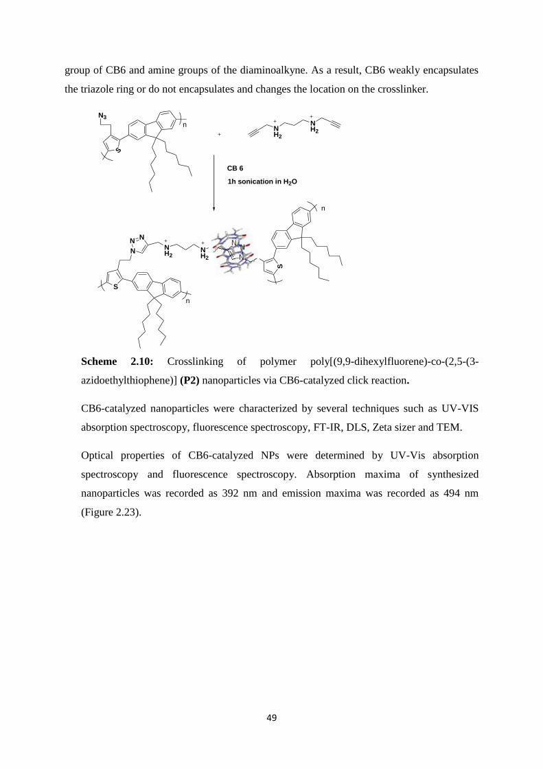
49
group of CB6 and amine groups of the diaminoalkyne. As a result, CB6 weakly encapsulates
the triazole ring or do not encapsulates and changes the location on the crosslinker.
S
N3
n
S
N
NN
NH2
NH2 N
NN
S
n
n
NH2
NH2
1h sonication in H2O
CB 6
Scheme 2.10: Crosslinking of polymer poly[(9,9-dihexylfluorene)-co-(2,5-(3-
azidoethylthiophene)] (P2) nanoparticles via CB6-catalyzed click reaction.
CB6-catalyzed nanoparticles were characterized by several techniques such as UV-VIS
absorption spectroscopy, fluorescence spectroscopy, FT-IR, DLS, Zeta sizer and TEM.
Optical properties of CB6-catalyzed NPs were determined by UV-Vis absorption
spectroscopy and fluorescence spectroscopy. Absorption maxima of synthesized
nanoparticles was recorded as 392 nm and emission maxima was recorded as 494 nm
(Figure 2.23).

50
Figure 2.23: Absorption and emission spectra of polymer poly[(9,9-dihexylfluorene)-co-(2,5-
(3-azidoethylthiophene)] (P2) nanoparticles in water synthesized via CB6-catalyzed click
reaction (λabs = 392 nm, λexc = 392 nm, λem = 494 nm).
Converting P2 polymer into nanoparticles resulted in a significant change in the emission
spectrum when it was compared with the emission spectrum of P2 polymer. A distinct red-
shift in the emission spectrum was observed as in the emission spectrum of the CPNs
synthesized via Cu(I)-catalyzed click reaction. This red-shift is due to the chain-chain
interactions of the polymer converted to nanoparticles which is the result of pi-pi stacking
between the aromatic groups of the polymer in the backbone. However red-shift in the
emission spectrum of CPNs synthesized via Cu(I)-catalyzed click reaction is much more
significant when it is compared with the emission spectrum of CPNs synthesized via CB6-
catalyzed click reaction. CB6 units which act as a guest for the formed triazole after the click
reaction decrease the chain-chain interactions of the aromatic groups in the polymer and cause
a less significant red-shift in the emission spectrum of the CPNs (Figure 2.24).
392 nm
494 nm

51
Figure 2.24: Emission spectra of the polymer poly[(9,9-dihexylfluorene)-co-(2,5-(3-
azidoethylthiophene)] (P2) in THF, P2 nanoparticles in water synthesized via Cu(I)-
catalyzed click reaction and P2 nanoparticles in water synthesized via CB6-catalyzed click
reaction.
FT-IR spectroscopy was used to characterize the CPNs synthesized via CB6-catalyzed
click reaction in order to determine if the triazole formation was successful or not. The
samples were prepared by dropping the nanoparticle solution in water on the silicon
wafer. After drying of silicon wafers, FT-IR spectrum was recorded. In the FT-IR
spectrum, the characteristic azide peak at 2094cm-1
should have decreased and the
characteristic carbonyl stretching band around 1730cm-1
should have detected because of
the CB6 catalyst. According to spectrum, click reaction was successful and desired
triazole was formed because the desired peaks were observed in the FT-IR spectrum.
Azide peak significantly decreased and carbonyl stretching band detected in the spectrum.
This FT-IR spectrum confirms the formation of a triazole and the presence of CB6 in the
nanoparticle (Figure 2.25).
457 nm
511 nm
494 nm

52
Figure 2.25: FT-IR (silicon wafer, cm-1
) spectrum of the polymer poly[(9,9-
dihexylfluorene)-co-(2,5-(3-azidoethylthiophene)] (P2) nanoparticles synthesized via
CB6-catalyzed click reaction.
Figure 2.26: FT-IR (silicon wafer, cm-1
) spectra of the polymer poly[(9,9-
dihexylfluorene)-co-(2,5-(3-azidoethylthiophene)] (P2) and P2 nanoparticles synthesized
via CB6-catalyzed click reaction.
The hydrodynamic size of the CPNs synthesized via CB6-catalyzed click reaction was
determined by using DLS. Sizes of the nanoparticles synthesized via Cu(I)-catalyzed click
Carbonyl Streching

53
reaction and CB6-catalyzed click reaction were almost the same according to DLS results.
Diameter of the CB6-catalayzed nanoparticles was recorded as 71nm (Figure 2.27)
Figure 2.27: DLS data of of the polymer poly[(9,9-dihexylfluorene)-co-(2,5-(3-
azidoethylthiophene)] (P2) nanoparticles synthesized via CB6-catalyzed click reaction.
Potential difference between the water and the stationary layer of fluid which was attached
to the nanoparticle surface was determined by zeta potential. Zeta potential of the CPNs
was measured as -25.5 mV (Figure 2.28).
Figure 2.28: Zeta-potential of the polymer poly[(9,9-dihexylfluorene)-co-(2,5-(3-
azidoethylthiophene)] (P2) nanoparticles synthesized via CB6-catalyzed click reaction.
CPNs synthesized via CB6-catalyzed click reaction were also characterized by TEM.
CPNs were synthesized by using hydrophilic diaminoalkyne. The click reaction between
the hydropobic polymer P2 and hydrophilic crosslinker diaminoalkyne was resulted with a
patchy, janus-like nanoparticles. Janus-like nanoparticles attract the variety of research
areas because of their important role in theranostic nanomedicine (Figure 2.29).
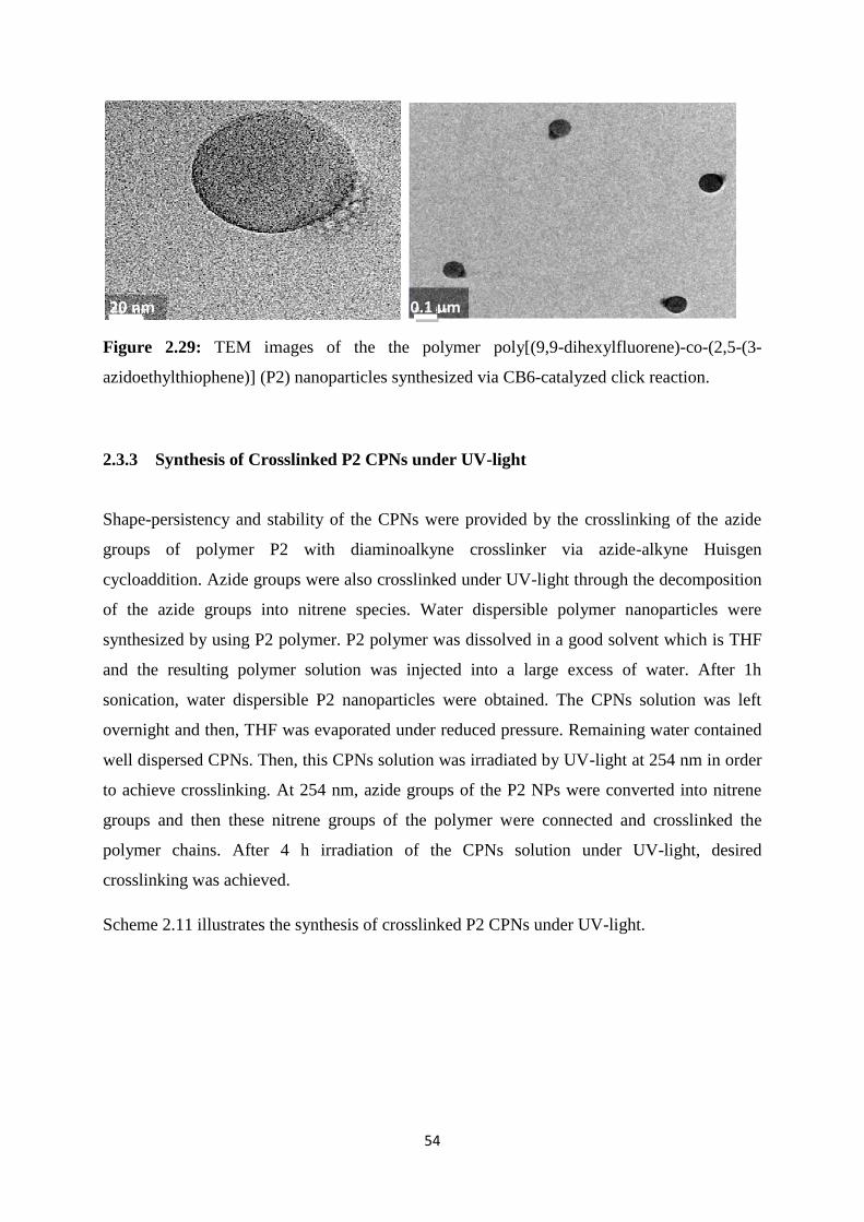
54
Figure 2.29: TEM images of the the polymer poly[(9,9-dihexylfluorene)-co-(2,5-(3-
azidoethylthiophene)] (P2) nanoparticles synthesized via CB6-catalyzed click reaction.
2.3.3 Synthesis of Crosslinked P2 CPNs under UV-light
Shape-persistency and stability of the CPNs were provided by the crosslinking of the azide
groups of polymer P2 with diaminoalkyne crosslinker via azide-alkyne Huisgen
cycloaddition. Azide groups were also crosslinked under UV-light through the decomposition
of the azide groups into nitrene species. Water dispersible polymer nanoparticles were
synthesized by using P2 polymer. P2 polymer was dissolved in a good solvent which is THF
and the resulting polymer solution was injected into a large excess of water. After 1h
sonication, water dispersible P2 nanoparticles were obtained. The CPNs solution was left
overnight and then, THF was evaporated under reduced pressure. Remaining water contained
well dispersed CPNs. Then, this CPNs solution was irradiated by UV-light at 254 nm in order
to achieve crosslinking. At 254 nm, azide groups of the P2 NPs were converted into nitrene
groups and then these nitrene groups of the polymer were connected and crosslinked the
polymer chains. After 4 h irradiation of the CPNs solution under UV-light, desired
crosslinking was achieved.
Scheme 2.11 illustrates the synthesis of crosslinked P2 CPNs under UV-light.
20 nm 0.1 μm

55
Scheme 2.11: Synthesis of the crosslinked P2 CPNs under UV-light.
Optical properties of crosslinked P2 CPNs were determined by UV-Vis absorption
spectroscopy and fluorescence spectroscopy. Absorption maxima of synthesized
nanoparticles was recorded as 382 nm and emission maxima was recorded as 500 nm
(Figure 2.30).
Figure 2.30: Absorption and emission spectrum of the crosslinked P2 CPNs in water under
UV-light (λabs = 382 nm, λexc = 382 nm, λem = 500 nm).
Crosslinking of the nanoparticles under UV-light was resulted with a red-shift in the emission
spectrum because of more π-π stacking in the polymer backbone. Figure 2.31 illustrates the
emission spectrum of crosslinked CPNs under UV-light.
382 nm 500 nm
S
HN
nS
N3
n
irradiation under 254 nm
HN
NHS
S
S
n
S
S
OR

56
Figure 2.31: Emission spectra of the polymer P2 CPNs in water crosslinked under UV-light
in 1 h, 2 h, 3 h, and 4 h, respectively.
FT-IR spectroscopy was used to characterize the crosslinked CPNs under UV-light in order to
determine if the crosslinking was successful or not. The samples were prepared by dropping
the nanoparticle solution in water on the silicon wafer. After drying of silicon wafers, FT-IR
spectrum was recorded (Figure 2.32).
Figure 2.32: FT-IR (silicon wafer, cm-1
) spectrum of the polymer P2 and crosslinked P2
CPNs under UV-light.
In the FT-IR spectrum, the characteristic azide peak at 2094cm-1
should have decreased as
a result of the crosslinking and nitrene formation. According to spectrum, crosslinking

57
was successful because the mentioned key peak was significantly decreased in the FT-IR
spectrum. This confirms the successful crosslinking under UV-light.
The hydrodynamic size of the crosslinked CPNs under UV-light was determined by using
DLS. Diameter of the nanoparticles were recorded as 34 nm (Figure 2.33).
Figure 2.33: DLS data of the crosslinked CPNs under UV-light.
Potential difference between the water and the stationary layer of fluid which was attached
to the nanoparticle surface was determined by zeta potential. Zeta potential of the
crosslinked CPNs was measured as -33.3 mV (Figure 2.34).
Figure 2.34: Zeta-potential of the crosslinked CPNs under UV-light.
The CPNs crosslinked under UV-light were also characterized by TEM. Spherical
nanoparticles were obtained which agree with the DLS results (Figure 2.35).

58
Figure 2.35: TEM images of the crosslinked P2 CPNs under UV-light.
20 nm 0.1 μm

59
CHAPTER 3
CONCLUSION
In this study, a novel synthetic method was demonstrated for the water-soluble conjugated
polymer nanoparticles with enhanced chemical and mechanical stability. Crosslinked
conjugated polymer nanoparticles were synthesized by a diaminoalkyne crosslinker and
various useful functional groups were introduced to the nanoparticles such as triazoles and
amine groups which can be used in electrostatic drug-polymer binding. They make the
synthesized nanoparticles highly versatile for biological studies such as cell imaging and drug
delivery in biological systems.
Incorporation of the hydrophilic functional groups to the conjugated polymer nanoparticles
resulted with patchy, janus-like nanoparticles because of the distinct phase separation. They
can be utilized in theranostic nanomedicine studies. In this project, CB6 was used as a catalyst
for the first time in nanoparticle synthesis for 1,3-azide alkyne Huisgen cycloaddition which
formed a conjugated polymer-based nanosized rotaxanes.
Crosslinking of the conjugated polymer nanoparticles was also achieved by the irradiation of
the nanoparticles under UV light. Synthesized nanoparticles can be used in cell imaging and
theranostic nanomedicine.

60
CHAPTER 4
EXPERIMENTAL
Cucurbit[6]uril (CB6) and N,N’-di-prop-2-ynyl-propane-1,3-diamine hydrochloride were
synthesized according to the literature.42
The reagents and solvents used in this project were
purchased from Sigma-Aldrich Chemical Co. They were used as received without further
purification. Purification of the monomers was established by the column chromatography
with the silica gel (Kieselgel 60, 0.063-0.200 mm). Structural characterization of monomers
and polymers was performed by nuclear magnetic resonance (NMR, Bruker Avance III 400
MHz spectrometer). CDCl3 was used as a solvent in all NMR measurements. Structures of the
polymers and nanoparticles were also verified by fourier transform infrared spectroscopy (FT-
IR, Bruker TENSOR 27). Polymers dissolved in THF and nanoparticles in water were
dropped onto the silicon wafers. The spectrum was recorded at 25 ± 1 oC in the mid-IR
spectral range (4000 cm-1
– 400 cm-1
). 256 scans were accumulated for each sample with a
resolution of 4 cm-1
. Molecular weights of the polymers were measured by gel permeation
chromatography (GPC, Agilent 1200). THF was used as an eluent and polystyrene was used
as a standard. Mass to charge ratio of the charged polymers were measured by electrospray
ionization mass spectrometry (Agilent, 6224 TOF LC/MS). Optical properties of the polymers
and nanoparticles were characterized by a UV-Vis spectrophotometer (Cary UV-Vis) and a
fluorescence spectrophotometer (Cary Eclipse Fluorescent spectrophotometer). A xenon lamp
was used as the excitation source. The sizes of the nanoparticles were determined by dynamic
light scattering (DLS, Zetasizer Nano-ZS) measurements. All the measurements were carried
out at 633 nm at room temperature. Laser was used as a light source during the measurements.
Average particle diameters were calculated by the Marquardt method. All DLS measurements
were repeated 3 times for each sample and the average values were reported. Zeta potentials
of the nanoparticles were also measured with the same zetasizer (Zetasizer Nano-ZS).
Morphological properties of the nanoparticles were characterized by transmission electron
microscopy (TEM, FEI Tecnai G2 F30). The nanoparticle solution in water was purified via
dialysis with a regenerated cellulose tubular membrane (Cellu.Sep T3, MWCO: 12 000–14
000, dry cylinder diameter: 21.0 mm, flat width: 33 nm, length: 30 m, vol cm-1
: 3.47 ml).

61
4.1 Synthesis of 2-(2,5-dibromothiophen-3-yl)ethanol (M1)
2-(3-thienyl)ethanol (2.5 g, 20 mmol) and N-bromosuccinimide (NBS) (7.1 g, 40 mmol) were
dissolved in DMF (25 mL) as a mixture. Then it was stirred at 40 °C for 12 h under nitrogen.
For the work-up, the mixture was cooled to room temperature. It was washed with diethyl
ether and water. The organic layer was collected and dried over Na2SO4. Product was purified
by silica packed column chromatography. Hexane was used as an eluent. Yield: 4.5 g, 64%
1H-NMR (400 MHz, CDCl3, δ): 6.81 (s, 1H), 4.19 (t,
3J = 6.8, 2H), 2.84 (t,
3J = 6.8, 2H),
2.04 (s, 1H).
S
OH
BrBr
M1
4.2 Synthesis of 2,5-dibromo-3-(2-bromoethyl)thiophene (M2)
2-(2,5-dibromothiophen-3-yl)ethanol (M1) (4.5 g, 15.7 mmol) and PPh3 (4.03 g, 15.40
mmol) were dissolved in 10mL THF as a mixture and cooled in the ice bath. To this
mixture, CBr4 (5.10 g, 15.40 mmol) in 5 mL THF was added dropwise and the reaction
mixture was stirred for 12h under nitrogen. For the work-up, solvent was evaporated
under reduced pressure and the remaining residue was washed with dichloromethane and
water. Then organic layer was collected and washed with brine, dried over Na2SO4.
Product was purified by silica packed column chromatography. Hexane was used as an
eluent. Yield: 1.5 g, 27%
1H-NMR (400 MHz, CDCl3, δ): 6.84 (s, 1H), 3.47 (t,
3J = 7.2, 2H), 3.08 (t,
3J = 7.4, 2H).

62
S
Br
BrBr
M2
4.3 Synthesis of 3-(2-bromoethyl)thiophene (M3)
2-(3-thienyl)ethanol ( 2.5 mL, 22.6 mmol) and PPh3 (7.1g, 27.1 mmol) were dissolved in
10mL THF as a mixture and cooled in the ice bath. To this mixture, CBr4 (9.0 g, 27.1
mmol) in 10 mL THF was added dropwise and the reaction mixture was stirred for 12 h
under nitrogen. For the work-up, solvent was evaporated under reduced pressure and the
remaining residue was washed with dichloromethane and water. Then organic layer was
collected and washed with brine, dried over Na2SO4. Product was purified by silica
packed column chromatography. Hexane was used as an eluent. Yield: 2.3 g, 79%
1H-NMR (400 MHz, CDCl3, δ): 7.27 (m, 1H), 7.05 (m, 1H), 6.96 (dd, 1H), 3.55 (t,
3J =
7.6, 2H), 3.19 (t, 3J = 7.6, 2H).
S
Br
M3

63
4.4 Synthesis of 2-(thiophen-3-yl)-N,N,N-trimethylethanammoniumbromide (M4)
3-(2-bromoethyl)thiophene (M3) (2.0 g, 0.01 mol) was dissolved in a minimum amount of
THF (5 mL) and added to 25% trimethylamine solution in H2O (100 mL). The resulting
reaction mixture was stirred for 4 days at RT. For the work-up, the excess trimethylamine
solution was evaporated under reduced pressure. Resulted precipitates were washed with
hexane:acetone (1:1) mixture. Collected white precipitates were dried at 50 oC for 24h in
vacuum. Yield: 1.0 g, 59%.
1H-NMR (400 MHz, MeOD, δ): 7.47 (m, 1H), 7.28 (m, 1H), 7.10 (dd, 1H), 3.60 (m, 2H),
3.21 (m, 2H), 3,17 (s, 9H).
S
N Br
M4
4.5 Synthesis of poly[(9,9-dihexylfluorene)-co-(2,5-(3-bromoethylthiophene) (P1)
2,5-Dibromo-3-(2-bromoethyl)thiophene M2 (500 mg, 1.43 mmol), the boronic ester of
fluorene (720 mg, 1.43 mmol) and K2CO3 (1.88 g) were dried under vacuum for 30 min.
To this mixture, degassed toluene (10 ml), water (10 ml) and THF (10 ml) were added.
The reaction mixture was stirred for 10 min under nitrogen and Pd(Ph3)4 (17 mg, 0.0143
mmol) was added. Resulting mixture was heated to 80 oC for 3 h and then TBAB (46 mg)
was added. The reaction mixture was stirred for 48 h at 80 oC under nitrogen. For the
work-up, the reaction mixture was poured into a large amount of cold methanol. The
precipitated product was collected by suction filtration and washed with water to remove
K2CO3. The remaining water insoluble residues were dissolved in a minimum amount of
THF and poured into cold methanol. The precipitates were collected and dried under
vacuum for 6 h to yield a yellow powder. Yield: 715 mg, 59%
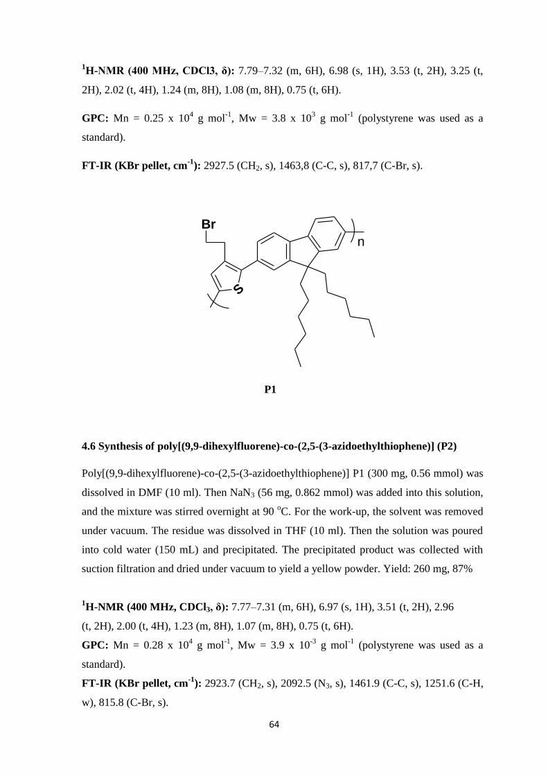
64
1H-NMR (400 MHz, CDCl3, δ): 7.79–7.32 (m, 6H), 6.98 (s, 1H), 3.53 (t, 2H), 3.25 (t,
2H), 2.02 (t, 4H), 1.24 (m, 8H), 1.08 (m, 8H), 0.75 (t, 6H).
GPC: Mn = 0.25 x 10⁴ g mol
-1, Mw = 3.8 x 10
3 g mol
-1 (polystyrene was used as a
standard).
FT-IR (KBr pellet, cm-1
): 2927.5 (CH2, s), 1463,8 (C-C, s), 817,7 (C-Br, s).
S
Br
n
P1
4.6 Synthesis of poly[(9,9-dihexylfluorene)-co-(2,5-(3-azidoethylthiophene)] (P2)
Poly[(9,9-dihexylfluorene)-co-(2,5-(3-azidoethylthiophene)] P1 (300 mg, 0.56 mmol) was
dissolved in DMF (10 ml). Then NaN3 (56 mg, 0.862 mmol) was added into this solution,
and the mixture was stirred overnight at 90 oC. For the work-up, the solvent was removed
under vacuum. The residue was dissolved in THF (10 ml). Then the solution was poured
into cold water (150 mL) and precipitated. The precipitated product was collected with
suction filtration and dried under vacuum to yield a yellow powder. Yield: 260 mg, 87%
1H-NMR (400 MHz, CDCl3, δ): 7.77–7.31 (m, 6H), 6.97 (s, 1H), 3.51 (t, 2H), 2.96
(t, 2H), 2.00 (t, 4H), 1.23 (m, 8H), 1.07 (m, 8H), 0.75 (t, 6H).
GPC: Mn = 0.28 x 10⁴ g mol
-1, Mw = 3.9 x 10
-3 g mol
-1 (polystyrene was used as a
standard).
FT-IR (KBr pellet, cm-1
): 2923.7 (CH2, s), 2092.5 (N3, s), 1461.9 (C-C, s), 1251.6 (C-H,
w), 815.8 (C-Br, s).
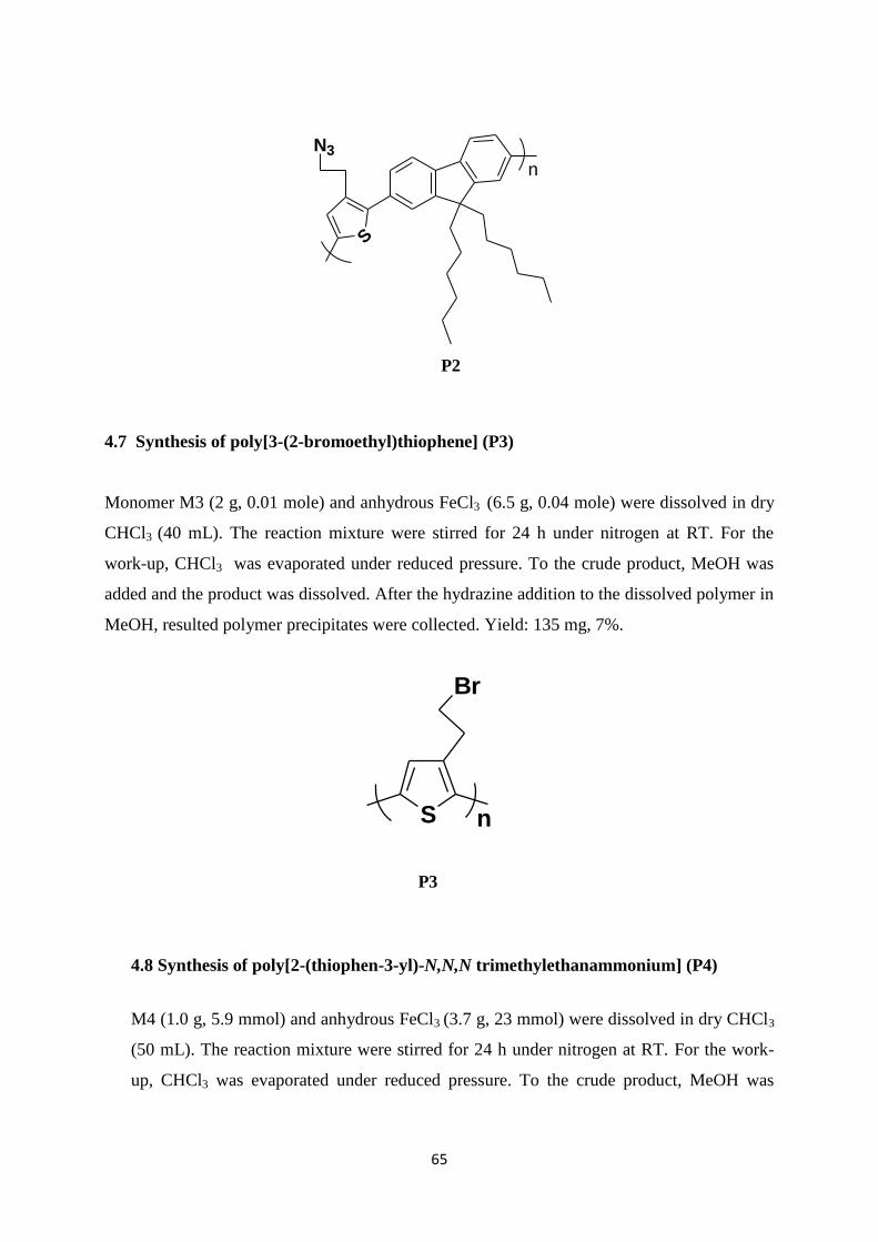
65
S
N3
n
P2
4.7 Synthesis of poly[3-(2-bromoethyl)thiophene] (P3)
Monomer M3 (2 g, 0.01 mole) and anhydrous FeCl3 (6.5 g, 0.04 mole) were dissolved in dry
CHCl3 (40 mL). The reaction mixture were stirred for 24 h under nitrogen at RT. For the
work-up, CHCl3 was evaporated under reduced pressure. To the crude product, MeOH was
added and the product was dissolved. After the hydrazine addition to the dissolved polymer in
MeOH, resulted polymer precipitates were collected. Yield: 135 mg, 7%.
S
Br
n
P3
4.8 Synthesis of poly[2-(thiophen-3-yl)-N,N,N trimethylethanammonium] (P4)
M4 (1.0 g, 5.9 mmol) and anhydrous FeCl3 (3.7 g, 23 mmol) were dissolved in dry CHCl3
(50 mL). The reaction mixture were stirred for 24 h under nitrogen at RT. For the work-
up, CHCl3 was evaporated under reduced pressure. To the crude product, MeOH was

66
added and the product was dissolved. After the hydrazine addition to the dissolved
polymer in MeOH, resulted polymer precipitates were collected. Yield: 266 mg, 27%.
S
N
n
P4
4.9 Synthesis of CPNs via Cu(I)-catalyzed Click Reaction
P2 (0.01 mmol) was dissolved in THF (10 mL). Then the polymer solution was filtered
through a 0.45 mm syringe filter. Crosslinker N,N’-di-prop-2-ynylpropane-1,3-diamine
hydrochloride (0.005 mmol) was dissolved in water (500 ml). Then immediately CuSO4
(5.0 x 10⁻⁵
mmol) and ascorbic acid (1.0 x10⁻⁴
mmol) were added to this solution. The
polymer solution in THF was injected rapidly into the CuSO4 and ascorbic acid containing
water solution under vigorous stirring. The resulting mixture was sonicated for 1h at room
temperature. Synthesized nanoparticles were left overnight at room temperature and then
THF was evaporated under reduced pressure. The remaining nanoparticle solution in
water was concentrated to a total volume of 100 ml. Purification was done via dialysis for
24 h using a 14 kDa MWCO regenerated cellulose membrane to remove the catalyst and
any unreacted species.
FT-IR (silicon wafer, cm-1
): 2925.6 (CH2, s), 1859.1 (C=C, s), 1627.7 (C=C, s), 1450.3
(C-C, s), 1107.0 (C-N, s), 889.1 (N-H, w).

67
S
N
NN
NH2
NH2 N
NN
S
n
n
Cu(I) NP
4.10 Synthesis of CPNs via CB6-catalyzed Click Reaction
P2 (0.01 mmol) was dissolved in THF (10 ml). Then the polymer solution was filtered
through a 0.45 mm syringe filter. Crosslinker N,N’-di-prop-2-ynylpropane- 1,3-diamine
hydrochloride (0.005 mmol) was dissolved in water (5 ml). Then immediately CB6 (0.005
mmol) was added to this solution. The mixture was stirred for 30 min to obtain a clear
solution. The resulting solution was filtered through a 0.45 mm syringe filter and its
volume was increased to 500 ml by adding deionized water. The polymer solution in THF
was injected rapidly into the CB6 containing water solution under vigorous stirring. The
resulting mixture was sonicated for 1 h at room temperature. Synthesized nanoparticles
were left overnight at room temperature and then THF was removed under reduced
pressure. The remaining nanoparticle solution in water was concentrated to a total volume
of 100 ml. Purification was done via dialysis for 24 h using a 14 kDa MWCO regenerated
cellulose membrane to remove the excess CB6 and any unreacted species.
FT-IR (silicon wafer, cm-1
): 2935.3 (CH2, s), 1716.4 (C=O, s), 1606.5 (C=C, s), 1458.0
(C-C, s), 1261.3 (C-H, w), 1107.0 (C-N, s), 815.8 (C-Br, s).

68
S
N
NN
NH2
NH2 N
NN
S
n
n
CB6 NP
4.11 Synthesis of Crosslinked P2 NPs under UV-light
P2 (0.01 mmol) was dissolved in THF (10mL). After 10 minutes sonication, P2 solution
in THF was poured into the 500 mL water rapidly under vigorous stirring. The resulting
mixture was sonicated 1h at room temperature. Synthesized nanoparticles were left
overnight at room temperature and then THF was evaporated under reduced pressure.The
remaining nanoparticle solution in water was concentrated to a total volume of 100 mL.
Then nanoparticle solution was irradiated by UV-light at 256 nm for 4h. Resulting
crosslinked nanoparticles were characterized by FT-IR spectrometer.
FT-IR (silicon wafer, cm-1
): 2921.8 (CH2, s), 2098.3 (N3, s).
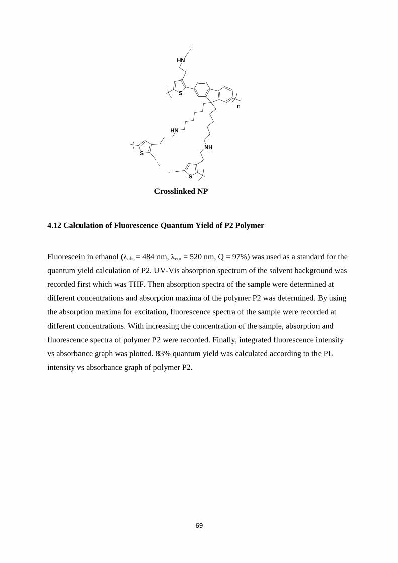
69
S
HN
n
HN
NHS
S
Crosslinked NP
4.12 Calculation of Fluorescence Quantum Yield of P2 Polymer
Fluorescein in ethanol (λabs = 484 nm, λem = 520 nm, Q = 97%) was used as a standard for the
quantum yield calculation of P2. UV-Vis absorption spectrum of the solvent background was
recorded first which was THF. Then absorption spectra of the sample were determined at
different concentrations and absorption maxima of the polymer P2 was determined. By using
the absorption maxima for excitation, fluorescence spectra of the sample were recorded at
different concentrations. With increasing the concentration of the sample, absorption and
fluorescence spectra of polymer P2 were recorded. Finally, integrated fluorescence intensity
vs absorbance graph was plotted. 83% quantum yield was calculated according to the PL
intensity vs absorbance graph of polymer P2.
70
REFERENCES
1. Chiang, C. K.; Fincher, C. R., Jr.; Park, Y. W.; Heeger, A. J.; Shirakawa, H.; Louis, E.
J.; Gau, S. C.; MacDiarmid, A. G., Electrical Conductivity in Doped Polyacetylene. Phys.l
Rev. Lett. 1977, 39, (17), 1098-1101.
2. http://en.wikipedia.org/wiki/File:Polythiophenes_Conjugation.png.
3. Nobel, The Nobel Prize in Chemistry 2000; Conductive Polymers. 2000.
4. Natta, G., Kinetic studies of α-olefin polymerization. J. Polymer Sci. 1959, 34, (127),
21-48.
5. Ito, T.; Shirakawa, H.; Ikeda, S., Simultaneous polymerization and formation of
polyacetylene film on the surface of concentrated soluble Ziegler-type catalyst solution. J.
Polymer Sci. Polymer Chem. 1974, 12, (1), 11-20.
6. Imamura, A.; Aoki, Y., Molecular design of a π-conjugated single-chain electronically
conductive polymer. Int. J. Quantum Chem. 2006, 106, (8), 1924-1933.
7. http://www.files.chem.vt.edu/chem-ed/quantum/bands.html.
8. Burroughes, J. H., Light emitting diodes based on conjugated polymers. Nature 1990.
9. R.Silbey, J. L. B., Conjugated Polymers The Novel Science and Technology of Highly
Conducting and Nonlinear Optically Active Materials. 1991, 9-11.
10. 2010, N., NOBEL 2010 Palladium-catalyzed Cross Couplings in Organic Synthesis.
2010.
11. Chujo, Y., Conjugated Polymer Synthesis Methods and Reactions. 2010.
12. Heck, R. F.; Nolley, J. P., Palladium-catalyzed vinylic hydrogen substitution reactions
with aryl, benzyl, and styryl halides. J. Org. Chem. 1972, 37, (14), 2320-2322.
13. Negishi, E.; King, A. O.; Okukado, N., Selective carbon-carbon bond formation via
transition metal catalysis. 3. A highly selective synthesis of unsymmetrical biaryls and
diarylmethanes by the nickel- or palladium-catalyzed reaction of aryl- and benzylzinc
derivatives with aryl halides. J. Org. Chem. 1977, 42, (10), 1821-1823.
14. Miyaura, N.; Yamada, K.; Suzuki, A., A new stereospecific cross-coupling by the
palladium-catalyzed reaction of 1-alkenylboranes with 1-alkenyl or 1-alkynyl halides.
Tetrahedron Lett. 1979, 20, (36), 3437-3440.
71
15. Yamamura, M.; Moritani, I.; Murahashi, S.-I., The reaction of σ-vinylpalladium
complexes with alkyllithiums. Stereospecific syntheses of olefins from vinyl halides and
alkyllithiums. J. Organomet. Chem. 1975, 91, (2), C39-C42.
16. Feng, X.; Liu, L.; Wang, S.; Zhu, D., Water-soluble fluorescent conjugated polymers
and their interactions with biomacromolecules for sensitive biosensors. Chem. Soc. Rev. 39,
(7).
17. Gaylord, B. S.; Heeger, A. J.; Bazan, G. C., DNA detection using water-soluble
conjugated polymers and peptide nucleic acid probes. PNAS 2002, 99, (17), 10954-10957.
18. Tuncel, D.; Demir, H. V., Conjugated polymer nanoparticles. Nanoscale 2, (4).
19. Pecher, J.; Mecking, S., Nanoparticles of Conjugated Polymers. Chem. Rev. 110, (10),
6260-6279.
20. Müller, K.; Klapper, M.; Müllen, K., Synthesis of Conjugated Polymer Nanoparticles
in Non-Aqueous Emulsions. Macromol. Rapid Commun. 2006, 27, (8), 586-593.
21. Berkefeld, A.; Mecking, S., Mechanistic Studies of Catalytic Polyethylene Chain
Growth in the Presence of Water. Angew. Chem. Int. Ed. 2006, 45, (36), 6044-6046.
22. Baier, M. C.; Huber, J.; Mecking, S., Fluorescent Conjugated Polymer Nanoparticles
by Polymerization in Miniemulsion. J. Am. Chem. Soc. 2009, 131, (40), 14267-14273.
23. Szymanski, C.; Wu, C.; Hooper, J.; Salazar, M. A.; Perdomo, A.; Dukes, A.; McNeill,
J., Single Molecule Nanoparticles of the Conjugated Polymer MEH−PPV, Preparation and
Characterization by Near-Field Scanning Optical Microscopy. J. Phys. Chem. B 2005, 109,
(18), 8543-8546.
24. Ho Moon, J.; Deans, R.; Krueger, E.; Hancock, L. F., Capture and detection of a
quencher labeled oligonucleotide by poly(phenylene ethynylene) particles. Chem. Commun.
2003, (1), 104-105.
25. Piok, T.; Gadermaier, C.; Wenzl, F. P.; Patil, S.; Montenegro, R.; Landfester, K.;
Lanzani, G.; Cerullo, G.; Scherf, U.; List, E. J. W., The photophysics of organic
semiconducting nanospheres: a comprehensive study. Chem. Phys. Lett. 2004, 389, 7-13.
26. Kurokawa, N.; Yoshikawa, H.; Hirota, N.; Hyodo, K.; Masuhara, H., Size-Dependent
Spectroscopic Properties and Thermochromic Behavior in Poly(substituted thiophene)
Nanoparticles. ChemPhysChem 2004, 5, (10), 1609-1615.
27. Huebner, C. F.; Roeder, R. D.; Foulger, S. H., Nanoparticle Electroluminescence:
Controlling Emission Color Through Förster Resonance Energy Transfer in Hybrid Particles.
Adv. Funct. Mater. 2009, 19, (22), 3604-3609.

72
28. Grigalevicius, S.; Forster, M.; Ellinger, S.; Landfester, K.; Scherf, U., Excitation
Energy Transfer from Semi-Conducting Polymer Nanoparticles to Surface-Bound Fluorescent
Dyes. Macromol. Rapid Commun. 2006, 27, (3), 200-202.
29. Rahim, N. A. A.; McDaniel, W.; Bardon, K.; Srinivasan, S.; Vickerman, V.; So, P. T.
C.; Moon, J. H., Conjugated Polymer Nanoparticles for Two-Photon Imaging of Endothelial
Cells in a Tissue Model. Adv. Mater. 2009, 21, (34), 3492-3496.
30. Moon, J. H.; McDaniel, W.; MacLean, P.; Hancock, L. F., Live-Cell-Permeable
Poly(p-phenylene ethynylene). Angew. Chem. Int. Ed. 2007, 46, (43), 8223-8225.
31. Kolb, H. C.; Finn, M. G.; Sharpless, K. B., Click Chemistry: Diverse Chemical
Function from a Few Good Reactions. Angew. Chem. Int. Ed. 2001, 40, (11), 2004-2021.
32. Binder, W. H.; Sachsenhofer, R., ‘Click’ Chemistry in Polymer and Material Science:
An Update. Macromol. Rapid Commun. 2008, 29, (12-13), 952-981.
33. Johnson, J. A.; Finn, M. G.; Koberstein, J. T.; Turro, N. J., Construction of Linear
Polymers, Dendrimers, Networks, and Other Polymeric Architectures by Copper-Catalyzed
Azide-Alkyne Cycloaddition “Click” Chemistry. Macromol. Rapid Commun. 2008, 29, (16),
1421-1421.
34. Joralemon, M. J.; O'Reilly, R. K.; Hawker, C. J.; Wooley, K. L., Shell Click-
Crosslinked (SCC) Nanoparticles:  A New Methodology for Synthesis and Orthogonal
Functionalization. J.Am. Chem. Soc. 2005, 127, (48), 16892-16899.
35. O'Reilly, R. K.; Joralemon, M. J.; Hawker, C. J.; Wooley, K. L., Preparation of
orthogonally-functionalized core Click cross-linked nanoparticles. New J.Chem. 2007, 31, (5),
718-724.
36. Li, C.; Finn, M. G., Click chemistry in materials synthesis. II. Acid-swellable
crosslinked polymers made by copper-catalyzed azide–alkyne cycloaddition. J. Polym. Sci.,
Part A: Polym. Chem. 2006, 44, (19), 5513-5518.
37. Jiang, X.; Zhang, J.; Zhou, Y.; Xu, J.; Liu, S., Facile preparation of core-crosslinked
micelles from azide-containing thermoresponsive double hydrophilic diblock copolymer via
click chemistry. J. Polym. Sci. Part A: Polym. Chem. 2008, 46, (3), 860-871.
38. Such, G. K.; Tjipto, E.; Postma, A.; Johnston, A. P. R.; Caruso, F., Ultrathin,
Responsive Polymer Click Capsules. Nano Lett. 2007, 7, (6), 1706-1710.
39. Zou, J., Well-Defined Drug-Conjugated Biodegradable Nanoparticles by
Azide–Alkyne Click Crosslinking in Miniemulsion. Polym. Chem. 2011.

73
40. Taranekar, P.; Qiao, Q.; Jiang, H.; Ghiviriga, I.; Schanze, K. S.; Reynolds, J. R.,
Hyperbranched Conjugated Polyelectrolyte Bilayers for Solar-Cell Applications. J. Am.
Chem. Soc. 2007, 129, (29), 8958-8959.
41. Li, C.; Numata, M.; Bae, A.-H.; Sakurai, K.; Shinkai, S., Self-Assembly of
Supramolecular Chiral Insulated Molecular Wire. J. Am. Chem. Soc. 2005, 127, (13), 4548-
4549.
42. Tuncel, D.; Katterle, M., pH-Triggered Dethreading–Rethreading and Switching of
Cucurbit[6]uril on Bistable [3]Pseudorotaxanes and [3]Rotaxanes. Chem. Eur. J. 2008, 14,
(13), 4110-4116.