SynJet Augmented Cooling for Cloud Computing
24
SynJet Augmented Cooling for Cloud Computing Raghav Mahalingam
Transcript of SynJet Augmented Cooling for Cloud Computing

SynJet Augmented Cooling for Cloud Computing Raghav Mahalingam

[2]
The Evolution of Computing
Computing systems are moving in two opposing directions
– Cloud computing that handles the heavy computing workload, data
handling and processing
This requires high efficiency, high heat dissipation cooling of microprocessors, TCO is important
– Portable “clients” that handle input/output and display media, such as
tablets and smartphones
This requires low form factor, “zero” power consumption cooling to cool RF devices, video chips etc.
Confidential
Cloud computers
Client computers

[3]
Nuventix SynJets : Next Generation Cooling
Low flow rate, high turbulence airflow – Efficient
Cooling systems that are whisper quiet – Quiet
Products that are immune to contaminants – Rugged
Lifetimes in excess of 30 years at 60 C ambient – Long Lifetime
Low power consumption – Green
Confidential

[4]
Overview
SynJet Technology
– Motivation for SynJets
– SynJet principles
– Heat transfer with SynJets
– Standalone Chip cooling
SynJets for Augmentation of Fans
– Principle of localized augmentation
– Wind tunnel experiments
– Case study of a fan cooled server
augmented with Synjets

[5]
The “bottleneck” is airside heat transfer
RTIM1 ~ 0.1-0.2 C/W
Die Junction
Rdie ~ varies a lot, and
typically hard to affect
Ambient
Rhs, spreading ~ 0.1-0.2 C/W
Rairside ~ 0.5-1 C/W
• All heat that is not reused has to be finally dumped into
air, water or the ground
• Cooling volume ~ 100 cc
• Die size ~ 10mm x 10mm
• TIM ~ 10-20 mm2 C/W ~ 0.1- 0.2 C/W
• Air side ~ 0.5 - 1 C/W

[6]
Diminishing returns on airflow
Moffat, R., “Modeling Air-Cooled Heat Sinks as Heat Exchangers,” Proc. of the 23rd IEEE Semi-Therm Conference, 2007.
• The heat exchanger model includes an effectiveness,
• As mass flow increases, heat transfer coefficient doesn’t increase as fast as
mass flow (i.e., its less than linear)
• Thus, as mass flow increases, effectiveness decreases
• The way to increase effectiveness is to increase h at a given mass flow rate
)1( mCp
hA
e
0.75
0.8
0.85
0.9
0.95
0 1 2 3 4
Eff
ecti
ven
ess
Flow rate, CFM
entrained cool air Heat rejected to ambient
Texit Tambient Tfluid
Twall

[7]
20
40
60
x/h
diaphragm
ambient air
entrainment
SynJet
vortices
time averaged axial velocity decay
SynJet Principles
• Unsteady turbulent jet
• Operates without net mass injection
• Synthesized from surrounding fluid
• Net momentum transfer to the flow
t/T = 0.36
2 0 4 0 6 0 8 0
0 . 3
0 . 4
0 . 5
0 . 6
0 . 7 0 . 8 0 . 9
1
m = - 0 . 5
u/U 0
z/b 2 0 4 0 6 0 8 0
0 . 3
0 . 4
0 . 5
0 . 6
0 . 7 0 . 8 0 . 9
1
m = - 0 . 5
Glezer, A., and Amitay, M., “Synthetic Jets”, Annual Review of Fluid Mechanics, 2002
[8]
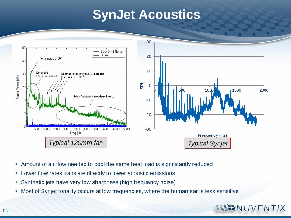
Figure 1a: The emerging pulse of air
Figure 1b: The pulse has moved away from the nozzle
– Note the large velocity vectors associated with the vortices
accompanying the SynJet pulse formation
Figure 1c: Pulse has moved further away down the heatsink
– Entrained air can be seen behind it in the form of the large velocity
vectors all pointing in the direction of the pulse
Figure 1d: Tail of the pulse is seen
Figure 1e: Pulse has almost fully left the frame
– air can be seen recharging the nozzle in preparation for the next pulse
Figure 1a Figure 1b Figure 1c Figure 1d Figure 1e
Evolution of a SynJet: Velocity

[9]
SynJet Ejectors
• High momentum primary jet “drags” along ambient air
• Significant flow entrainment by jet ejector effect
• Entrained flow up to an order of magnitude higher than jet flow
• Net momentum transfer to the flow
• Significant flow mixing
SynJet
Ejectors
Induced secondary flow
SynJet
Oscillating diaphragm
Primary Synjet

[10]
Secondary Flow Entrainment
Smoke visualization shows entrainment effect
The SynJet module expels high momentum pulses of air
A low pressure area is created behind the pulse
Nearby ambient air is pulled or entrained into the low pressure area and travels along with the turbulent pulse

[11]
Thermal Management Metrics
• Thermal resistance: total heat dissipation, flux density
• Acoustics: loudness, psychoacoustics
• Power consumption: COP, controllability
• Reliability: MTTF, harsh environments
• Cooling volume and weight: Smaller is always better
• Form factor flexibility
• Manufacturability
Any thermal management technology has to
address multiple trade-offs

[12]
Nusselt number correlations
Nusselt numbers (i.e., heat transfer coefficient) for SynJet
cooling in a channel much higher than fully developed,
dynamically similar (i.e., same Re) steady duct flow
Thermal Efficiency
Nusselt Number, Nu = h . D / k
Reynolds Number, Re = U . D /n
SynJet
Tambient Tfluid
Twall heater
heater
Reynolds number
0
5
10
15
20
25
30
35
40
45
0 1000 2000 3000 4000
Synthetic jet Model Synthetic jet Experiment
Steady Turbulent Flow(8)
Nu
ssel
t nu
mb
er
(8) Gnielinski, V., Int. Chem.
Eng., 16, 359, 1976.
[13]
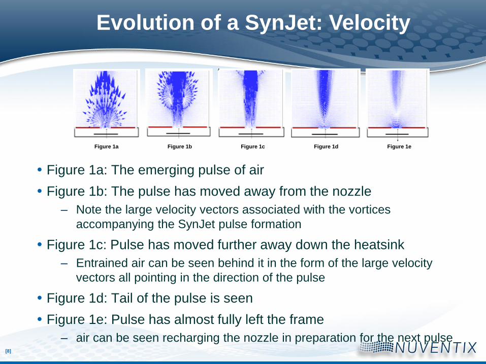
SynJet Acoustics
Amount of air flow needed to cool the same heat load is significantly reduced
Lower flow rates translate directly to lower acoustic emissions
Synthetic jets have very low sharpness (high frequency noise)
Most of Synjet tonality occurs at low frequencies, where the human ear is less sensitive
Typical 120mm fan
-30
-20
-10
0
10
20
30
0 500 1000 1500 2000
SP
L
Frequency (Hz)
Typical Synjet

[14]
SynJet Power Characteristics
SynJets are resonant systems, so the cooler can be designed to operate at
resonance.
Operating at resonance significantly reduces the power consumption of Synjets.
For example, for a CPU type 100W heat sink, fans typically have a COP of ~ 15-20.
Synjets can be designed to have COPs ~ 30-40.
Typical Synjet Power Distribution

[15]
SynJet Reliability
L10 data obtained from accelerated lifetime tests.
Achieved 300,000 hrs L10 @ 60C (34 years of 24x7 operation @60C)
High reliability due to the fact that Synjets have no moving parts in friction
SynJet
Vapo
Dual Ball
Single Ball
Fluid Dynamic
Sleeve
L10 Curve Comparison Chart
1000
10000
100000
1000000
10000000
20 30 40 50 60 70 80
Temperature, C
Lif
e,
Ho
urs
(L
10)
Schwickert, M., “Nuventix Reliability Report”, nuventix.com

[16]
Synjet Cooled Heat Sinks
MR16
PAR20 PAR25 PAR30
Universal 140 DLM Cooler Universal 120 DLM Cooler
XFlow 30
Spot Cooler
CoolTwist

[17]
SynJet Augmented Fan Cooling

[18]
Fan cooled server chassis SynJet Assisted Cooling
• Smaller, lower speed fan (enables low noise, cost, better
reliability)
• Increased heat transfer coefficient and flow rate through heat
sink (enables higher power processor)
Potential Advantages
Inlet
Outlet
Fan Augmentation
SynJet
Fan cooling without SynJet
microprocessor
Fan cooling with SynJet
Dual Fan
Synthetic Jet
Heat sink
microprocessor
Heat sink

[19]
Experimental Setup for augmentation tests
8 ” x 8 ” Test section
Velocity probe
Velocity probe Instrumented heat sink with heaters
SynJet
• Wind tunnel test cross section could be varied to achieve
different bypass ratios
• SynJet placed upstream of heat sink, directing airflow into the
heat sink.
• Flow velocities and heat sink thermals measured

[20]
Heat transfer enhancement with SynJets
y = 3.46x-0.34
y = 23.71x-0.61
0
0.1
0.2
0.3
0.4
0.5
0.6
0.7
0 500 1000 1500
Mean Fan Flow (LFM)
Th
erm
al re
sis
tan
ce
(C
/W) Fan Only
Fan + Jet
Improvement in thermal resistance due to jet augmentation
0
10
20
30
40
50
60
70
0 2 4 6 8
Ratio of Jet LFM to Mean LFM
% im
pro
ve
me
nt in
th
erm
al
pe
rfo
rma
nce
Percentage improvement in heat dissipation as a function of jet/fan LFM ratio.
Jet augmentation significantly decreases thermal resistance of heat sink
The key metric for determining performance improvement due to jet augmentation is the ratio of the jet velocity to freestream flow velocity

[21]
Augmentation Case Study
• 800W Newisys 4300 quad-socket, 3U, AMD Opteron rack-mounted model
server
• Inlet speed varied from 560(5500RPM) to 800 LFM(9000RPM)

[22]
Performance Augmentation in Mean Flows
Fan Only Fan + Jet
0
0.1
0.2
0.3
0.4
0.5
5500 6500 7500 9000
Baseline Fan RPM
Th
erm
al re
sis
tan
ce
(C
/W)
Cooling System Power Consumption and Acoustics Improvement in Thermal Performance
Using the synthetic jets helped reduce the speed of the system fans from
9000 to 6500RPM resulting in a – drop in cooling system power consumption from 108 to 62W
– drop in system acoustics from 75 to 65 dBA
– Reduction in Total Cost of Operation, due to lower power
consumption
Fan
RPM
Cooling System
power consumed
(including Synjets)
System
Acoustics
(including
Synjets)
9000 108W 75dBA
6500 62W 65dBA
Equivalent thermal performance

[23]
Effect on Cooling System Reliability
SynJet Assisted Augmentation
Fan at 6000 rpm
= 39 ppm
Chip at 80 °C
= 34 ppm
System = 83 ppm
Fan Cooling Only
Fan at 9000 rpm
= 58 ppm
Chip at 80 °C
= 34 ppm
System = 92 ppm
L10 = 25,000 hr
L10 = 28,000 hr
•Assumptions
•Fan reliability ~ 40000 hours L10 or 58ppm
•SynJet reliability ~250000 hours L10 or 10ppm
•One main fan
•Augmentation done with either 1 Synjet or 1 Additional Fan
SynJet
= 10 ppm
Fan Assisted Augmentation
Fan at 6000 rpm
= 39 ppm
Chip at 80 °C
= 34 ppm
System = 112 ppm
L10 = 20,000 hr
Fan at 6000 rpm
= 39 ppm

[24]
Summary
SynJets are turbulent, unsteady jets created by an oscillating diaphragm
SynJets provide high local heat transfer coefficients
Localized SynJets enable increased heat dissipation from fan cooled systems
The increased heat dissipation can be translated into lower fan speeds
Lower fan speeds result in overall improvement in cooling system acoustics, power and reliability and potentially, TCO.