SynfinityLink Guide Redundant Line Control Function - · PDF filePreface This manual describes...
189
SynfinityLink Guide Redundant Line Control Function
Transcript of SynfinityLink Guide Redundant Line Control Function - · PDF filePreface This manual describes...

SynfinityLink Guide
Redundant Line Control Function

Preface
This manual describes SynfinityLink function (Redundant Line Control Function) and explains the installation and operation management procedures.
Intended Reader
This manual is intended for the system manager who manages the implementation and operation of SynfinityLink (Redundant Line Control Function).
The manager is assumed to have an understanding of SynfinityCluster:, which is the fundamental program for cluster control.
Organization of This Manual This manual is organized as follows:
Chapter 1 Outline
This chapter provides an outline of SynfinityLink (Redundant Line Control Function).
Chapter 2 Functions
This chapter explains the line duplicating function provided by SynfinityLink (Redundant Line Control Function).
Chapter 3 Installation
This chapter explains how to operate setting up SynfinityLink (Redundant Line Control Function).
Chapter 4 Operation
This chapter explains how to operate SynfinityLink (Redundant Line Control Function).
Chapter 5 Operation on Cluster System
This chapter explains how to operate SynfinityLink (Redundant Line Control Function) on cluster system.
Chapter 6 Maintenance
This chapter describes the data required for a SynfinityLink (Redundant Line Control Function) troubleshooting.
Chapter 7 Command References
This chapter explains the commands provided by SynfinityLink (Redundant Line Control Function).
Appendix A Message List
This appendix explains the messages outputted by SynfinityLink (Redundant Line Control Function).
Appendix B Examples of Setting Up
This appendix describes examples of SynfinityLink (Redundant Line Control Function) setting up.
Appendix C Changes from old versions
This appendix describes the changes from SynfinityLink old versions.
Appendix D Others
This appendix describes the supplement matters.
Trademarks
UNIX is a trademark of X/Open Company limited and licensed exclusively by the company in the U.S.A. and other countries.
Solaris is a registered trademark of Sun Microsystems:, Inc. of the United States.
Ethernet is a registered trademark of Fuji Xerox Co.:, Ltd.
July 2001
i

ii
First edition: July 2001
Notes:
The contents of this document shall not be reproduced in any from without the prior permission of Fujitsu Limited. This document is subject to change without prior notice.
All Rights Reserved:, Copyright (C) FUJITSU LIMITED 2001

Chapter 1 Outline
1.1 What is SynfinityLink (Redundant Line Control Function)?
SynfinityLink (Redundant Line Control Function) is a software program that makes the network line of a local system redundant with several Network Interface Cards (NICs) to realize high-reliability communications.
SynfinityLink (Redundant Line Control Function) provides line control functions in the following four modes.
Fast switching mode
Fast switching mode enables the system to control lines by a unique method. In this method, multiplexed lines are used concurrently. In the event of a fault, the system cuts off the faulty line and operates on a reduced scale. The unique method allows early fault detection but is limited to remote systems using the same model. This mode cannot be used to communicate with a host on other networks connected via routers.
RIP mode
RIP mode enables the system to control lines by a standard protocol called Routing Information Protocol (RIP). In this mode, either of the duplicated paths is used according to RIP information. In the event of a fault, the system switches to the other path. The standard protocol allows communications with non-limited parties and also with host systems on other networks connected via routers. However, paths switching in the RIP mode is slow and time-consuming.
1
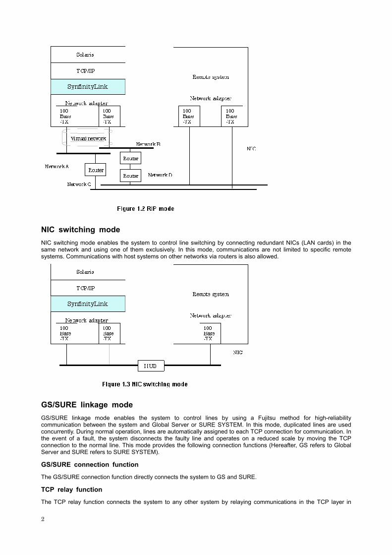
NIC switching mode
NIC switching mode enables the system to control line switching by connecting redundant NICs (LAN cards) in the same network and using one of them exclusively. In this mode, communications are not limited to specific remote systems. Communications with host systems on other networks via routers is also allowed.
GS/SURE linkage mode
GS/SURE linkage mode enables the system to control lines by using a Fujitsu method for high-reliability communication between the system and Global Server or SURE SYSTEM. In this mode, duplicated lines are used concurrently. During normal operation, lines are automatically assigned to each TCP connection for communication. In the event of a fault, the system disconnects the faulty line and operates on a reduced scale by moving the TCP connection to the normal line. This mode provides the following connection functions (Hereafter, GS refers to Global Server and SURE refers to SURE SYSTEM).
GS/SURE connection function
The GS/SURE connection function directly connects the system to GS and SURE.
TCP relay function
The TCP relay function connects the system to any other system by relaying communications in the TCP layer in
2

SURE. This function is available only on SURE.
3
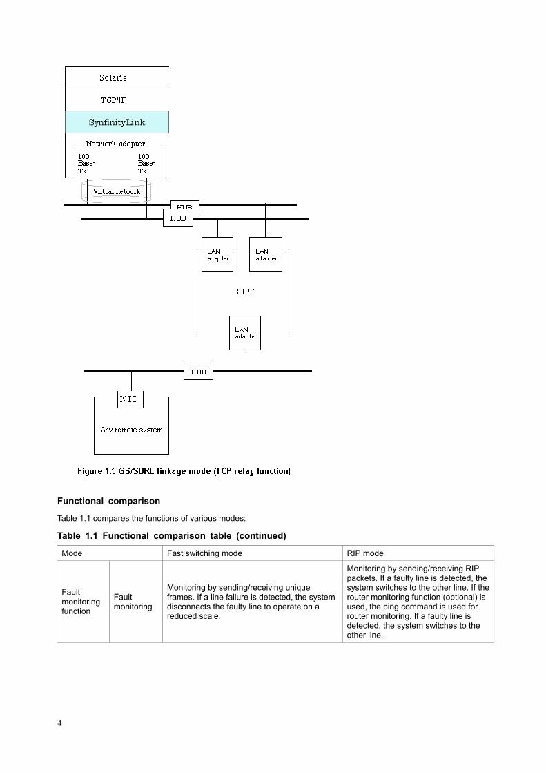
Functional comparison
Table 1.1 compares the functions of various modes:
Table 1.1 Functional comparison table (continued)
Mode Fast switching mode RIP mode
Fault monitoring function
Fault monitoring
Monitoring by sending/receiving unique frames. If a line failure is detected, the system disconnects the faulty line to operate on a reduced scale.
Monitoring by sending/receiving RIP packets. If a faulty line is detected, the system switches to the other line. If the router monitoring function (optional) is used, the ping command is used for router monitoring. If a faulty line is detected, the system switches to the other line.
4

Switching time About 10 seconds
If the router monitoring function is not used: about 5 minutes
If the router monitoring function is not used: about 1 to 5 minutes (depending on the setting and operating conditions)
Detectable failures NIC failure, cable failure, and HUB failure NIC failure, cable failure, HUB failure,
and router failure
Fault monitoring start/stop
The fault monitoring is started automatically when the Virtual interface is activated and is automatically stopped when the Virtual interface is inactivated.
The same as the left
Switching operation
NIC that cannot communicate is automatically disconnected. The faulty NIC can also be disconnected manually with an operational command.
The path is switched in accordance with the RIP routing information.
Switching function
Failback operation
The faulty NIC is monitored for recovery. When the NIC becomes capable of communication, the failback operation is automatically performed so that it can be reused for communication. The failback operation can also be performed manually with an operational command.
The failback of path is performed in accordance with the RIP routing information.
NIC sharing function (*1) In Fast switching mode, RIP mode, and Fast switching/RIP mode, all or some of the NICs can be shared.
The same as the left
Connectable remote device PRIMEPOWER,GP7000F
Any device. Fujitsu recommends using the Fujitsu LINLRELAY Series as the router to be connected on the local system.
*1 The NIC sharing function is a function with which the system operates in multiple line control mode using a pair of redundant NICs (this setup is stored in the so-called configuration information).
Table 1.1 Functional comparison table (end)
Mode NIC switching mode GS/SURE linkage mode
Fault monitoring
Monitoring of HUB by using the ping command. If a faulty line is detected, the system switches to the standby NIC.
Monitoring of the LAN adapter of the device with which communication is to be carried out by using the ping command. If a faulty line is detected, the system switches to the other path.
Switching time
About 10 seconds to 3 minutes (depending on the setting) The same as the left
Detectable failures NIC failure, cable failure, and HUB failure The same as the left
Fault monitoring function
Fault monitoring start/stop
The fault monitoring is started automatically when the Virtual interface (logical IP) is activated and is automatically stopped when the Virtual interface is inactivated. It is also possible to start/stop fault monitoring manually with an operational command.
The fault monitoring is started automatically when the Virtual interface is activated and is automatically stopped when the Virtual interface is inactivated. It is also possible to start/stop fault monitoring manually with an operational command.
Switching function
Switching operation
The currently operating Physical interface is made automatically to go down and then the standby Physical interface is made to go up. It is also possible to switch the Physical interface manually with an operational command.
NIC that cannot communicate is automatically disconnected. The faulty NIC cannot be disconnected manually.
5

Failback operation
The failback of an NIC can be performed manually with an operational command. The failback of an NIC is also performed automatically with the standby patrol function.
The faulty NIC is monitored for recovery. When the NIC becomes capable of communication, the failback operation is automatically performed so that it can be reused for communication. The failback operation cannot be performed manually.
NIC sharing function
NICs can be shared among multiple NIC switching modes only if all NICs are used under the same setup information stored within the same configuration information. If NICs are used under NIC switching mode, they cannot be shared with other modes.
Not allowed
Connectable remote device Any device
GS/SURE (if the GS/SURE communication function is used) or any device (if the TCP relay function is used)
Which of the four modes to use depends on the operating conditions of each system. Figure 1.6 shows the criteria for selecting the mode.
6

1.2 Benefits of SynfinityLink (Redundant Line Control Function)
SynfinityLink (Redundant Line Control Function) can construct high-reliability network with exellent fault resistance and availability.
7

1.3 System Configuration
Fast switching mode and RIP mode
NIC switching mode
8
GS/SURE linkage mode
9

SynfinityLink (Redundant Line Control Function) consists of the following components:
Main unit
PRIMEPOWER, GP7000F Series
NIC (Network Interface Cards)
The following Fujitsu adapters or cards can be used:
Basic Ethernet interface Ethernet adapter or card Fast Ethernet adapter or card Quad Fast Ethernet adapter or card Gigabit Ethernet adapter or card
Router (for operation in RIP mode)
The use of the following router is recommended:
Fujitsu LINKRELAY Series
HUB (for operation in NIC switching mode)
The following HUB can be used:
10

HUB to which IP address can be set
Operating system (OS)
Solaris 2.6 Solaris 7 (32-bit and 64-bit modes) Solaris 8 (32-bit and 64-bit modes)
Interfaces
SynfinityLink uses the following interface:
Physical interface
The Physical interface is an interface generated by each NIC. The interface name is determined by checking the NIC type (such as hmeX and qfeX). In GS/SURE linkage mode, however, the interface name is shaX because SynfinityLink (Redundant Line Control Function) constitutes a Physical interface.
Virtual interface
The Virtual interface is an interface (such as sha0 and sha1) generated by SynfinityLink (Redundant Line Control Function). TCP/IP applications using SynfinityLink (Redundant Line Control Function) conduct communications via a virtual network (virtual IP address) allocated to this interface. Even though the Virtual interface name is used as an identifier of the configuration information, in NIC switching mode, no virtual network is generated. In this case, a logical IP address is allocated to a real network. TCP/IP applications using SynfinityLink (Redundant Line Control Function) conduct communications via this logical IP address.
11

12

Chapter 2 Functions
2.1 Overview of Functions
2.1.1 Fast switching mode
In this mode, each multiple NIC (Network Interface Card) is connected to a different network and all of these NICs are activated and then used concurrently. Each packet that is to be sent is sent to an appropriate line based on the line conditions (whether any failure condition has occurred).
Also, an interface that is virtual (called a virtual interface in this document) is generated so that multiple NICs can be seen as one logical NIC. A TCP/IP application can conduct communication with the remote system, irrespective of the physical network redundant configuration, by using an IP address (called a virtual IP address in this document) set in this virtual interface as its own IP address of the local system.
Connection type
A system with which communication is to be carried out is connected to the same network and is not allowed to connect to a different network.
Features
In the event of a failure, lines can be switched swiftly in a short period of time without affecting the applications. Since redundant lines are all activated, each line can be used for different purposes, enabling the efficient use of resources.
Example of recommended application
This mode is appropriate, for example, to communications between the application server and database server in a three-tier client-server system.
System configuration
Figure 2.2 shows a system configuration for Fast switching mode:
13

The following explains each component and its meaning:
Physical interface
Indicates a physical interface (such as hme0 and hme1) of the duplicated NIC.
Physical IP
Indicates an IP address attached to a physical interface. This IP address is always active.
Virtual interface
Indicates a virtual interface (such as sha0) so that the duplicated NIC can be seen as one NIC.
Virtual IP
Indicates a local IP address to be allocated to the virtual interface for communication with remote devices.
2.1.1.1 Fault monitoring function
Fault monitoring
Sends a dedicated monitor frame to the other system's NIC at regular intervals (a default value is five seconds. Possible to change by the hanetparam command) and waits for a response. When received a response, decides that a route is normal, and uses it for communication until next monitoring. When received no response, decides that an error occurred, and not use it for communication until decides it is normal at next monitoring. Monitoring is done in an NIC unit that the other device equips.
14

Switching time
If a failure occurs in a multiplexed line, disconnecting the line takes about 10 seconds.
Detectable failures
The following failures can be detected:
Because the failures in (1) to (4) appear to be the same failure, it is not possible to determine under which of the four failure types these failures should be classified. Each device has to be checked to make this determination.
Fault monitoring start/stop
Monitoring is started automatically when the virtual interface is activated. Monitoring is automatically stopped when the virtual interface is inactivated. In cluster operation, the system allows each node to be started or stopped independently.
2.1.1.2 Switching function
Switching operation
A line whose failure is detected is automatically avoided, and only lines operating normally are used to continue communication. Therefore, if at least one normal line remains, communication can continue without system reactivation. It is also possible to disconnect a specific line manually by using the operational command (hanetnic command).
15

Failback operation
If the faulty line of a physical interface is recovered, the physical interface is automatically restored for normal communication. If a line was disconnected manually, the failback of the line needs to be performed manually to restore the original status.
2.1.1.3 NIC sharing function
All or some of the NICs are shared among configuration information for which Fast switching mode, RIP mode, or Fast switching/RIP mode is set. (Not possible to share NICs that the other modes use.)
16

2.1.1.4 Connectable remote device
PRIMEPOWER, GP7000F
2.1.1.5 Available application
TCP/IP application using the TCP or UDP protocol
2.1.1.6 Notes
- No multi-cast IP address can be used.
- See "2.1.2.6 Notes" as to making into a subnet when using together with RIP mode.
2.1.2 RIP mode
In this mode, each of multiple NIC (Network Interface Card) is connected to a different network and all these NICs are activated.
Just as in Fast switching mode, a virtual interface is generated and a virtual network is allocated to this interface. A TCP/IP application can conduct communication with the remote system, irrespective of the physical network redundant configuration, by using an IP address (called a virtual IP address in this document) set in this virtual interface as its own local system IP address.
The lines are monitored in accordance with the standard protocol on the Internet RIP (Routing Information Protocol). RIP is controlled by routing daemons (in.routed) on the Solaris system. The version of the routing daemons supported by the Solaris system is version 1.
17

Connection type
Routers are placed between systems to enable communicate between them, with each communication route comprising a different network.
Features
Because the Internet standard routing protocol RIP is used, communication can be carried out with a variety of devices in a global network environment regardless of the models. However, because the path switching by RIP is performed slowly, switching requires some time.
Recommended application areas
This mode is appropriate, for example, for the WEB server and communications between the application server and client machines in a three-tier client-server system.
System configuration
Figure 2.8 shows a system configuration for RIP mode:
18

The following explains each component and its meaning:
Physical interface
Indicates a physical interface (such as hme0 and hme1) of the duplicated NIC.
Physical IP
Indicates an IP address attached to a physical interface. This IP address is always active.
Virtual interface
Indicates a virtual interface (such as sha0) so that duplicated NIC can be seen as one NIC.
Virtual IP
Indicates a local IP address to be allocated to the virtual interface for communication with remote devices.
Monitored router 1
Indicates the IP address of a router to be monitored first when the router monitoring function is used.
Monitored router 2
Indicates the IP address of a router to be monitored after switching.
2.1.2.1 Fault monitoring function
Fault monitoring
The shortest path to the remote system is selected based on the RIP packet received from the neighboring router and the selected path is used for communication. Then, monitoring is carried out to check whether any RIP packet is received from the router. If a RIP packet is normally received, the transmission line is considered to be normal. If no RIP packet is received within a specified period of time, the transmission line is considered to be faulty and the line to be used for communication is switched in accordance with the routing information received from another router. Monitoring is carried out for each router connected to NIC. Routing control via RIP is performed by the Solaris system.
19

Switching time
If a failure occurs in a line, up to five minutes are required to switch the network paths via RIP.
Detectable failures
The following failures can be detected:
Because the failures in (1) to (4) appear to be the same failure, it is not possible to determine under which of the four failure types these failures should be classified. Each device has to be checked to make this determination.
Fault monitoring start/stop
Monitoring is started automatically when the virtual interface is activated. Monitoring is automatically stopped when the virtual interface is inactivated. In cluster operation, monitoring is started or stopped along with the start or stop of a service.
2.1.2.2 Switching function
Switching operation
The line is switched for use in communication in accordance with the routing information received from a router that is different from the router from which RIP was received.
20
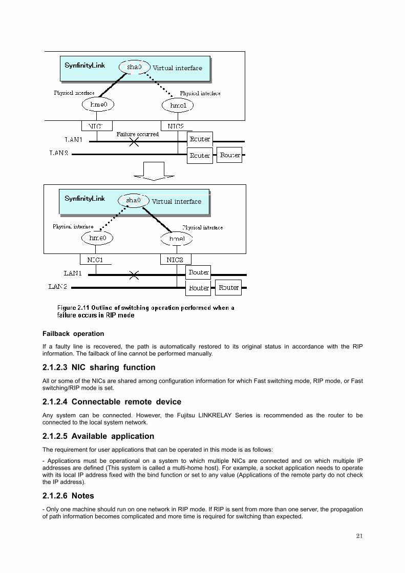
Failback operation
If a faulty line is recovered, the path is automatically restored to its original status in accordance with the RIP information. The failback of line cannot be performed manually.
2.1.2.3 NIC sharing function
All or some of the NICs are shared among configuration information for which Fast switching mode, RIP mode, or Fast switching/RIP mode is set.
2.1.2.4 Connectable remote device
Any system can be connected. However, the Fujitsu LINKRELAY Series is recommended as the router to be connected to the local system network.
2.1.2.5 Available application
The requirement for user applications that can be operated in this mode is as follows:
- Applications must be operational on a system to which multiple NICs are connected and on which multiple IP addresses are defined (This system is called a multi-home host). For example, a socket application needs to operate with its local IP address fixed with the bind function or set to any value (Applications of the remote party do not check the IP address).
2.1.2.6 Notes
- Only one machine should run on one network in RIP mode. If RIP is sent from more than one server, the propagation of path information becomes complicated and more time is required for switching than expected.
21
- No subnet can be created for a network to be used. Be sure to directly use a network of class A, B, or C without specifying a subnet mask. However, a subnet mask can be specified if the following conditions are met:
1) A subnet is created only for one network address.
2) A unique value in the entire network must be specified for the subnet mask for the network address for which a subnet is created.
3) A subnet mask value of the network address is defined in the /etc/netmasks file.
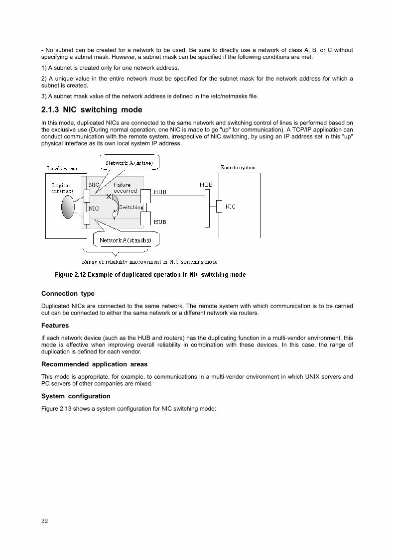
2.1.3 NIC switching mode
In this mode, duplicated NICs are connected to the same network and switching control of lines is performed based on the exclusive use (During normal operation, one NIC is made to go "up" for communication). A TCP/IP application can conduct communication with the remote system, irrespective of NIC switching, by using an IP address set in this "up" physical interface as its own local system IP address.
Connection type
Duplicated NICs are connected to the same network. The remote system with which communication is to be carried out can be connected to either the same network or a different network via routers.
Features
If each network device (such as the HUB and routers) has the duplicating function in a multi-vendor environment, this mode is effective when improving overall reliability in combination with these devices. In this case, the range of duplication is defined for each vendor.
Recommended application areas
This mode is appropriate, for example, to communications in a multi-vendor environment in which UNIX servers and PC servers of other companies are mixed.
System configuration
Figure 2.13 shows a system configuration for NIC switching mode:
22

The following explains each component and its meaning:
Primary physical interface
Indicates, of the duplicated NICs, the physical interface to be used first by activating it.
Secondary physical interface
Indicates the physical interface to be used after switching when a line failure is detected in the Primary physical interface.
Physical IP
Indicates an IP address attached to the Primary or Secondary physical interface. This IP address is always active.
Primary monitored IP
Indicates the IP address of a monitored device (HUB) obtained when the Primary physical interface is used.
Secondary monitored IP
Indicates the IP address of a monitored device (HUB) obtained when the Secondary physical interface is used.
Logical IP
Indicates a local IP address for communication with the remote device. When using a physical IP address takeover function, it is not activated.
2.1.3.1 Fault monitoring function
Fault monitoring
The ping command is issued periodically to the HUB connected to the NIC currently operating and its response is monitored. Optionally, HUB-HUB communication can be monitored.
If a failure is detected in the NIC currently operating, the system switches to the standby NIC and similar monitoring starts from the standby NIC side. Then, if a failure is also detected with the standby NIC, line monitoring stops.
23

Switching time
The switching time of a line is represented by [monitoring interval (sec) X monitoring count (count)] (for HUB-HUB communication monitoring, this is represented by [monitoring interval (sec) X monitoring count (count) X 2]). The monitoring interval can be set in the range of 1 to 300 seconds and the monitoring count can be set in the range of 1 to 300 times. By default, they are 5 seconds and 5 times respectively.
Even if the ping command failed immediately after started monitoring, it does not regard as an error occurred in a transfer route until [the time (sec) to wait for linkup] passed to wait for the Ethernet link to be established. Possible to set the time to wait for linkup in a range of 1 to 300, and a default value is 60 seconds. However, if a value is smaller than "the intervals to monitor x the number of the times to monitor", the time set for linkup is ignored and the time set by this "the intervals to monitor x the number of the times to monitor" is adopted.
Detectable failures
The following failures can be detected:
Because the failures in (1) to (3) appear to be the same failure, it is not possible to determine under which of the four
24
failure types these failures should be classified. Each device has to be checked to make this determination.
Monitoring start/stop timing
The line monitoring in NIC switching mode is automatically started when the system is activated and is automatically stopped when the system is stopped. In cluster operation, the line monitoring of each node is started and stopped independently. It is also possible to start or stop the line monitoring manually using the operational command (hanetpoll command).
2.1.3.2 Switching function
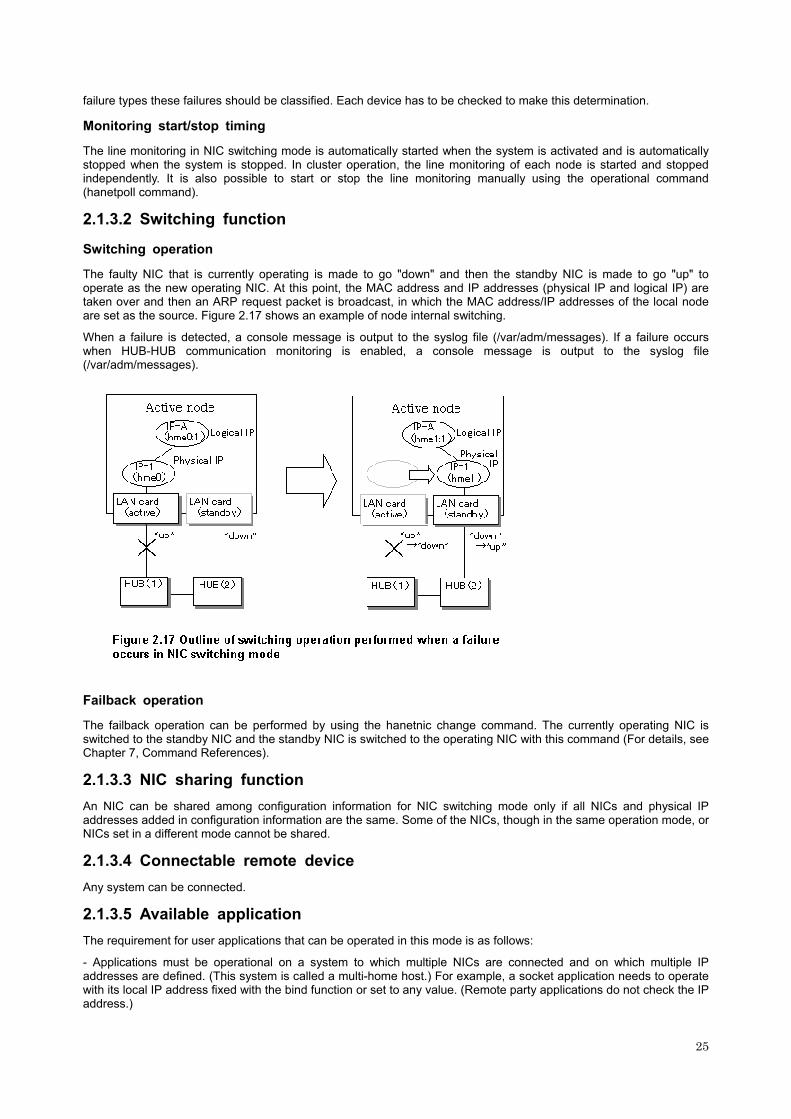
Switching operation
The faulty NIC that is currently operating is made to go "down" and then the standby NIC is made to go "up" to operate as the new operating NIC. At this point, the MAC address and IP addresses (physical IP and logical IP) are taken over and then an ARP request packet is broadcast, in which the MAC address/IP addresses of the local node are set as the source. Figure 2.17 shows an example of node internal switching.
When a failure is detected, a console message is output to the syslog file (/var/adm/messages). If a failure occurs when HUB-HUB communication monitoring is enabled, a console message is output to the syslog file (/var/adm/messages).
Failback operation
The failback operation can be performed by using the hanetnic change command. The currently operating NIC is switched to the standby NIC and the standby NIC is switched to the operating NIC with this command (For details, see Chapter 7, Command References).
2.1.3.3 NIC sharing function
An NIC can be shared among configuration information for NIC switching mode only if all NICs and physical IP addresses added in configuration information are the same. Some of the NICs, though in the same operation mode, or NICs set in a different mode cannot be shared.
2.1.3.4 Connectable remote device
Any system can be connected.
2.1.3.5 Available application
The requirement for user applications that can be operated in this mode is as follows:
- Applications must be operational on a system to which multiple NICs are connected and on which multiple IP addresses are defined. (This system is called a multi-home host.) For example, a socket application needs to operate with its local IP address fixed with the bind function or set to any value. (Remote party applications do not check the IP address.)
25

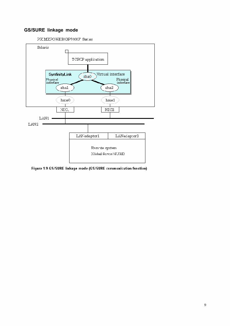
2.1.4 GS/SURE linkage mode
In this mode, each of multiple NICs (Network Interface Cards) is connected to a different network. Then, all the NICs are activated and used concurrently. Packets to be sent are assigned to the lines in units of TCP connections.
Thus, different lines are used for different connections for communication. If a failure occurs on one of the lines, communication can continue using another line, offering improved line reliability.
As with fast switching mode and RIP mode, a virtual interface is created and then a virtual network is allocated to it. A TCP/IP application can carry out communication with the remote system, irrespective of the physical network redundant configuration, by using a virtual IP address set in this virtual interface as its own local system IP address.
Connection type
If the GS/SURE linkage communication function is to be used, the systems among which communication is to be carried out must be connected on the same network. Connecting systems on different networks is not allowed.
If the TCP relay function is to be used, the local system and the remote system on a different network can communicate with each other via SURE.
26
Features
Lines are used in units of TCP connections for communication. If a failure occurs on a line, processing can continue on another line that is normal. Since all the redundant lines are activated for use, each of the lines can be directly used for a different purpose, enabling efficient use of resources.
Examples of recommended application
GS/SURE linkage mode is appropriate, for example, for communication in a multi-server environment where GS/SURE and GP are mixed or for IP-based reconstruction of network infrastructures of a legacy system.
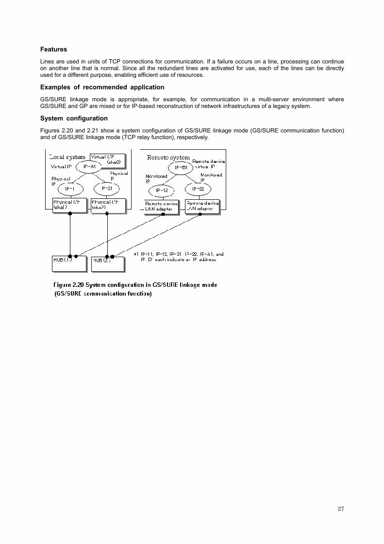
System configuration
Figures 2.20 and 2.21 show a system configuration of GS/SURE linkage mode (GS/SURE communication function) and of GS/SURE linkage mode (TCP relay function), respectively.
27

The following explains each component and its meaning:
Physical interface
Indicates a physical interface (such as sha1 and sha2) of the duplicated NIC.
Physical IP
Indicates an IP address to be attached to a physical interface. This IP address is always active. Use the IP address to manage a node by using the cluster management view, etc.
Virtual interface
Indicates a virtual interface (such as sha0) used to handle duplicated NICs as one NIC.
Virtual IP
Indicates a local IP address to be attached to a virtual interface for communication with remote devices. This IP address is activated on the active node. In cluster operation, the IP address is taken over by the standby node when clusters are switched.
Relay device LAN adapter and remote device NIC
Indicates a NIC of the relay and remote devices.
Monitored IP
Indicates an IP set to the NIC of the remote device. This IP address is monitored.
Remote device virtual IP
Indicates a virtual IP of the remote device with which communication should be carried out.
2.1.4.1 Fault monitoring function
Fault monitoring
The ping command is issued periodically to the LAN adapter of the remote system and its response is monitored. If no
28

response is received within a specified period of time, the line is considered to be faulty. Also, if a fault notification (with a special packet) of a line is received from the remote system, the line is considered to be faulty.
Switching time
The switching time of a line is indicated by [monitoring interval (sec) X monitoring count (count)]. The monitoring interval can be set in the range of 1 to 300 seconds and the monitoring count can be set in the range of 1 to 300 times. By default, they are 5 seconds and 5 times, respectively. Set the switching time of a line up to 300 seconds in consideration of the switching time required when RIP is operating.
Detectable failures
The following failures can be detected:
Fault monitoring start/stop
Monitoring is started automatically when the virtual interface is activated. Monitoring is automatically stopped when the virtual interface is inactivated.
2.1.4.2 Switching function
Switching operation
A line whose failure is detected is automatically avoided, and only lines operating normally are used to continue communication.
29

Failback operation
If a faulty path of a physical interface is recovered, the line of the physical interface is automatically restored for normal communication. The failback of a line cannot be performed manually.
2.1.4.3 NIC sharing function
The NIC sharing function cannot be used in this mode.
2.1.4.4 Connectable remote device
When using a GS/SURE communication function:
GS/SURE
When using a TCP relay function:
An optional system (Though a relay device is SURE only).
2.1.4.5 Available applications
The requirement for user applications that can be operated in this mode is as follows:
- The virtual IP address of SynfinityLink (Redundant Line Control Function) is set so that it is fixed as a local IP address using the bind function or others.
Thus, the Internet basic commands of Solaris such as ftp, telnet, and rlogin cannot be used in this mode.
2.1.4.6 Notes
When GS/SURE linkage mode is used, the system needs to be set as a multi-home host (in this case, an empty file called /etc/notrouter is created) instead of a router.
In this case, RIP mode or Fast switching/RIP mode cannot coexist. This mode cannot be used for communication between GPs.
2.2 Option Functions
The following option functions can be used in each mode.
Mode Function Fast switching
mode RIP mode
NIC switching mode
GS/SURE linkage mode
Multiple virtual interface definition function A A A A
Cluster failover function because of a line failure A A A A
Concurrent operation function with other modes via one virtual interface A (*1) A (*1) X X
Sharing function of physical interface A (*2) A (*2) A (*3) X
Multiple logical virtual interface definition function A A O X
Single physical interface definition function A A A A
Message output function when a line failure occurs A A (*4) A A
Router/HUB monitoring function O A (*4) S (*5) O
Communication party monitoring function A (*6) O O S (*7)
Standby patrol function O O A O
Dynamic adding/deleting/switching function of interfaces used A (*8) X A (*9) X
Automatic failback function O O A O
User command execution function X X A A
Explanation of symbols) S: Indispensable to set, A: Allowed, O: Replaced by other functions, X: Not allowed
30
*1: Concurrent operation between Fast switching mode and RIP mode is allowed. *2: All or some of the NICs can be shared between Fast switching mode and RIP mode, but cannot be shared with other modes. *3: Physical interfaces can be shared if all NICs and specified physical IP addresses are the same in the NIC duplicating mode. *4: This function can be used by setting the router monitoring function. *5: The HUB monitoring function can be used. Be sure to set this function when using the NIC switching function. *6: The remote party is automatically identified in Fast switching mode and then monitored. *7: When using GS/SURE linkage mode, be sure to set a function to monitor the other side to communicate. *8: In Fast switching mode, only the dynamic adding/deleting function of real interfaces can be used. *9: In NIC switching mode, only the dynamic switching function of interfaces used can be used.
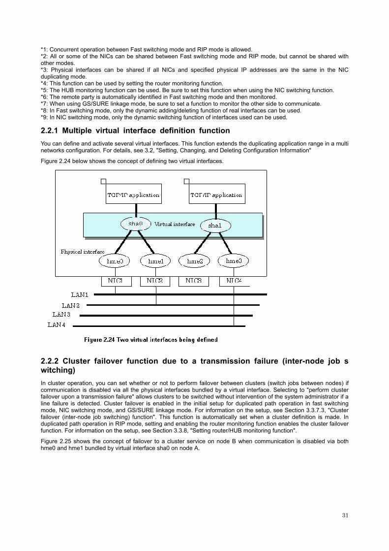
2.2.1 Multiple virtual interface definition function
You can define and activate several virtual interfaces. This function extends the duplicating application range in a multi networks configuration. For details, see 3.2, "Setting, Changing, and Deleting Configuration Information"
Figure 2.24 below shows the concept of defining two virtual interfaces.
2.2.2 Cluster failover function due to a transmission failure (inter-node job switching) In cluster operation, you can set whether or not to perform failover between clusters (switch jobs between nodes) if communication is disabled via all the physical interfaces bundled by a virtual interface. Selecting to "perform cluster failover upon a transmission failure" allows clusters to be switched without intervention of the system administrator if a line failure is detected. Cluster failover is enabled in the initial setup for duplicated path operation in fast switching mode, NIC switching mode, and GS/SURE linkage mode. For information on the setup, see Section 3.3.7.3, "Cluster failover (inter-node job switching) function". This function is automatically set when a cluster definition is made. In duplicated path operation in RIP mode, setting and enabling the router monitoring function enables the cluster failover function. For information on the setup, see Section 3.3.8, "Setting router/HUB monitoring function".
Figure 2.25 shows the concept of failover to a cluster service on node B when communication is disabled via both hme0 and hme1 bundled by virtual interface sha0 on node A.
31

2.2.3 Concurrent operation function with other modes via one virtual interface
You can operate both Fast switching mode and RIP mode concurrently via a single virtual interface. Fast switching mode is automatically selected for intra-network communications, and RIP mode for inter-network communications. A single virtual interface supports communications within the same network and between different networks. For details, see 3.2, "Setting, Changing, and Deleting Configuration Information"
Figure 2.26 shows the concept of Fast switching/RIP mode operation.
32

2.2.4 Sharing function of physical interface
Several virtual interfaces can share a single physical interface. Since the number of virtual interfaces sharing a single physical interface is not limited, resources can be shared effectively. In addition, you can set different operation configuration for each of the virtual interfaces sharing a single physical interface. For details, see 3.2, "Setting, Changing, and Deleting Configuration Information"
Figure 2.27 shows an example of virtual interfaces sha0 and sha1 sharing physical interface hme1.
33

2.2.5 Multiple logical virtual interface definition function
You can define several IP addresses (logical virtual interfaces) on a single virtual interface. The defined IP addresses can be used at the same time. This function enables IP addresses to be assigned without requiring additional physical interfaces. For details, see 3.2, "Setting, Changing, and Deleting Configuration Information"
Figure 2.28 shows an example of defining three logical virtual interfaces to virtual interface sha0.
In the above figure, sha0:2 to sha0:4 are called virtual interfaces in this document. For each logical virtual interface, assign an address within the same subnet as the virtual interface where the logical virtual interface belongs. For operation on a cluster system, assign an address in the same subnet as the takeover address.
2.2.6 Single physical interface definition function
You can create a virtual interface, which has single physical interface. This function enables failover because of a line failure even on a cluster system that has only one physical interface available for use. For details, see 3.2, "Setting, Changing, and Deleting Configuration Information"
34

Figure 2.29 shows an example of single physical interface configuration.
2.2.7 Message output function when a line failure occurs
If a line failure is detected on a physical interface, an error message is displayed on the console. This function enables the real-time recognition of a line failure.
For details about the Fast switching mode, see 3.3.7, "Setting message output function in response to a transmission line failure."
For details about the RIP mode or NIC switching mode, see 3.3.8, "Setting Router/HUB monitoring function."
For details about GS/SURE linkage mode, see 3.3.9, "Setting communication party monitoring function."
2.2.8 Router/HUB monitoring function
Router monitoring function
The router monitoring function switches lines by issuing the ping command to neighboring routers (up to two routers can be registered per virtual interface) at regular intervals and restarting in.routed if a line failure is detected. If the router monitoring function is disabled, about five minutes are required to switch lines when a failure is detected on a line. If the router monitoring function is enabled, the switching time can be reduced to about one minute (depending on the setting). (The switching time may not be reduced if a routing daemon is active on another node on the same network or if a line failure occurs in an unfavorable location on the line.) Additionally, enabling the router monitoring function enables a message to be output if a line failure occurs or clusters to be switched in cluster operation. Figure 2.30 shows the outline of the router monitoring function. When the operation starts, this function performs ping monitoring on the primary monitored router (router A in the figure). When a failure is detected in the primary monitored router, the routing daemon is restarted. Then, this function stops monitoring the primary monitored router and starts monitoring the secondary monitored router (router B in the figure).
Routers can be connected only between different networks.
Traffic is controlled in accordance with the RIP information using a single transmission line.
For information on the setup, see Section 3.3.8, "Setting router/HUB monitoring function".
35

HUB monitoring function
The HUB monitoring function issues the ping command to neighboring HUBs (up to two HUBs can be registered per virtual interface) at regular intervals and switches the interface to be used if a line failure is detected. This function can also monitor a line between two HUBs (inter-HUB monitoring function). This function can thus prevent a communication error from occurring due to NIC switching when an inter-HUB failure occurs. Figure 2.31 shows an outline of the HUB monitoring function.
If the operation starts without using the inter-HUB monitoring function, the primary HUB (HUB1 in the figure) is monitored using the ping command. When a failure is detected in the primary HUB, the NIC of the currently active system is inactivated and then the NIC of the current standby system is activated. After the standby NIC is activated, the secondary HUB (HUB2 in the figure) is monitored using the ping command. If the secondary HUB is faulty before switching and then a switching event occurs, communication after interface switching may not be executed normally.
If the operation starts using the inter-HUB monitoring function, the secondary HUB (HUB2 in the figure) is monitored using the ping command. When a failure is detected in the secondary HUB, the primary HUB (HUB1 in the figure) is monitored using the ping command. (At this point, a message is output, notifying that the monitoring of the secondary HUB has failed. Find the cause of the failure.) If, later, a failure is detected in the primary HUB, the NIC of the currently active system is inactivated and then the NIC of the current standby system is activated. After the standby NIC is activated, the primary HUB (HUB1 in the figure) is monitoring using the ping command. When a failure is detected in the primary HUB, the secondary HUB (HUB2 in the figure) is monitored using the ping command. Even if the secondary HUB is faulty before switching, recovery can be made before a switching event occurs because a message is output.
Be careful of the switching time setting (the product of values specified in the "-s" and "-c" options of the hanetpoll on command) because switching takes twice as long when the inter-HUB monitoring function is used as when it is not used. For information on the setup, see Section 7.7, "hanetpoll Command".
While the standby patrol function (see Section 2.2.10, "Standby patrol function") is used, the inter-HUB monitoring need not be used because the former serves also as the latter.
For information on the setup, see Section 3.3.8, "Setting router/HUB monitoring function".
36

2.2.9 Communication party monitoring function
In GS/SURE linkage mode, the ping command is issued to the IP address of the real interface of the communication party at regular intervals. If a line failure is detected, a message is output and communication continues using other transmission paths.
2.2.10 Standby patrol function
In NIC switching mode, the real interface status of the inactive standby system is monitored. When a failure occurs, a message is output. This helps to prevent line switching when a real interface failure occurs in the currently operating system and a failure has already occurred in the real interface of the standby system. It is also possible to cut off and
37
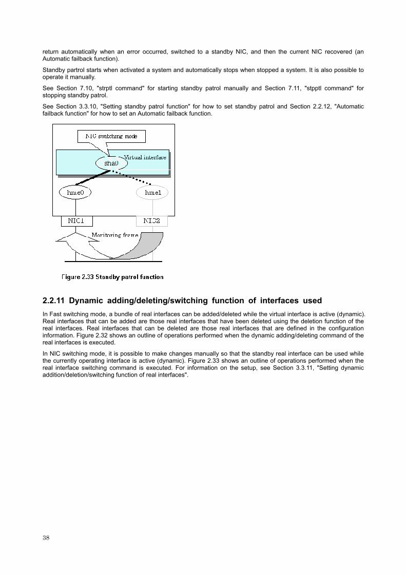
return automatically when an error occurred, switched to a standby NIC, and then the current NIC recovered (an Automatic failback function).
Standby partrol starts when activated a system and automatically stops when stopped a system. It is also possible to operate it manually.
See Section 7.10, "strptl command" for starting standby patrol manually and Section 7.11, "stpptl command" for stopping standby patrol.
See Section 3.3.10, "Setting standby patrol function" for how to set standby patrol and Section 2.2.12, "Automatic failback function" for how to set an Automatic failback function.
2.2.11 Dynamic adding/deleting/switching function of interfaces used
In Fast switching mode, a bundle of real interfaces can be added/deleted while the virtual interface is active (dynamic). Real interfaces that can be added are those real interfaces that have been deleted using the deletion function of the real interfaces. Real interfaces that can be deleted are those real interfaces that are defined in the configuration information. Figure 2.32 shows an outline of operations performed when the dynamic adding/deleting command of the real interfaces is executed.
In NIC switching mode, it is possible to make changes manually so that the standby real interface can be used while the currently operating interface is active (dynamic). Figure 2.33 shows an outline of operations performed when the real interface switching command is executed. For information on the setup, see Section 3.3.11, "Setting dynamic addition/deletion/switching function of real interfaces".
38

39

2.2.12 Automatic failback function
In NIC switching mode, use the standby patrol function to "automatically perform failback immediately after the primary interface recovers" or "perform failback when the secondary interface currently used encounters a failure". For information on the setup, see Section 3.3.10, "Setting standby patrol function". Figure 2.36 shows the outline of the automatic failback function.
40

2.2.13 User command execution function
In NIC switching mode and GS/SURE linkage mode, a user-defined command can be executed. For information on the setup, see Section 3.3.12, "Setting user command execution function".
In NIC switching mode, a user command is executed if switching occurs due to a monitoring failure (LAN failure, HUB
41

failure, etc.).
In GS/SURE linkage mode, a user command is executed if GS is in the hot standby configuration and nodes are switched.
Timing of executing a user command in various modes is shown in Figures 2.37, "Execution timing in NIC switching mode (logical IP address takeover function)", 2.38, "Execution timing in NIC switching mode (physical IP address takeover function), and 2.39, "Execution timing in GS/SURE linkage mode".
42

2.3 Notes
2.3.1 General - The maximum number of definitions for virtual and logical virtual interfaces is a total of 64.
- The number of physical interfaces in a single virtual interface is from 1 to 8.
- The maximum number of logical virtual interfaces that can be defined to a single logical virtual interface is 63.
43

44
2.3.2 Duplicated operation by Fast switching mode
- SynfinityLink (Redundant Line Control Function) must be operating on each system that performs duplicated operation by Fast switching mode.
2.3.3 Duplicated operation by RIP mode
- For duplicated operation by RIP mode, a pair of network interfaces must be connected through at least one router.
- If a fault occurs on an inter-system path during duplicated operation by RIP mode, some time is required to modify the path information between routers (about 5 minutes if the router polling function is not enabled, or 1 to 5 minutes if the function is enabled). If the TCP connection is reset during this period, reconnect for recovery from the fault.
- When setting a router (LR) for duplicated operation by RIP mode, the metric value of the network path must be different for each network.
2.3.4 Duplicated operation by Fast switching/RIP mode
- Not possible to define more than one virtual interface of Fast switching/RIP mode on the same network. It might not be able to communicate normally.
2.3.5 Duplicated operation via NIC switching mode
- One unit of HUB to be connected in NIC switching mode is sufficient, but communication may not be conducted normally if the HUB has MAC learning capabilities. In such a case, add a HUB to make a HUB-HUB connection and then connect the cable to each HUB (See "Figure 2.13 System configuration in NIC switching mode" of "2.1.3 NIC switching mode").
- Not possible to use a standby patrol function when the type of interface to use is "mpnetX (a logical interface of a multipath)".
2.3.6 Duplicated operation via GS/SURE linkage mode
- In GS/SURE linkage mode, the system uses duplicated paths concurrently but this cannot be expected improve the throughput.
- Be sure to set a function to monitor the other side to communicate when using GS/SURE linkage mode. See "7.5 hanetobserv command" as to how to set.

Chapter 3 Installation
This chapter explains how to setting up SynfinityLink (Redundant Line Control Function).
The following is setting up procedure:
3.1 System Setup
This section explains how to set up the system to use SynfinityLink (Redundant Line Control Function). For more information, see the manuals of Solaris.
3.1.1 Setup common to modes
Define in the /etc/inet/hosts file the host names (host names to be attached to virtual IP, monitored host names to be specified in monitoring destination information, etc.) to be specified in environment definitions of SynfinityLink (Redundant Line Control Function). These host names must be specified in the /etc/inet/hosts file even if no host names but IP addresses are directly specified in environment definitions.
To use other name services such as DNS or NIS operation, you are recommended to define the keywords for hosts and netmasks so that they first refer to a local file (/etc/nsswitch.conf file) first. (This way, address resolution normally terminates even if no communication is enabled with the DNS or NIS server.)
For more information, see the manuals of Solaris.
3.1.2 System setup in RIP switching mode
Set up the system to start up a routing daemon.
Do not create an /etc/defaultrouter file because path information must be dynamically changed. (Check for the existence of an etc/defaultrouter file and, if one exists, rename or delete it.)
For SynfinityLink (Redundant Line Control Function), the path information must be initialized and the routing daemon must be restarted. If path information is statically specified, the static paths must be described in /etc/gateways.
3.1.3 System setup in Fast switching/RIP mode
Set up the system to start up a routing daemon.
Do not create an /etc/defaultrouter file because path information must be dynamically changed. (Check for the existence of an etc/defaultrouter file and, if one exists, rename or delete it.)
For SynfinityLink (Redundant Line Control Function), the path information must be initialized and the routing daemon must be restarted. If path information is statically specified, the static paths must be described in /etc/gateways.
45
3.1.4 System setup in NIC switching mode
For SynfinityLink (Redundant Line Control Function), the path information must be initialized and the routing daemon must be restarted. If path information is statically specified, the static paths must be described in /etc/gateways.
3.1.5 System setup in GS/SURE linkage mode
Create an /etc/notrouter file.
Do not create an /etc/defaultrouter file because path information must be dynamically changed. (Check for the existence of an etc/defaultrouter file and, if one exists, rename or delete it.)
For SynfinityLink (Redundant Line Control Function), the path information must be initialized and the routing daemon must be restarted. If path information is statically specified, the static paths must be described in /etc/gateways.
The actual interface to be specified must not be defined for normal use in TCP/IP.
(You must check for the existence of an etc/hostname.interface file and, if one exists, rename or delete it and reboot the machine.)
3.2 Setting, Changing, and Deleting Configuration Information
3.2.1 Setting configuration information
This section explains procedures of setting various definition information such as virtual interfaces and monitoring function to be used for SynfinityLink (Redundant Line Control Function).
3.2.1.1 Adding configuration information for Fast switching mode
The following shows the procedure for adding configuration information for Fast switching mode:
1. Set up a virtual interface using the hanetconfig create command. For information, see Section 7.1, "hanetconfig Command".
3.2.1.2 Adding configuration information for RIP mode
The following shows the procedure for adding configuration information for RIP mode:
1. Set up a virtual interface using the hanetconfig create command. For information, see Section 7.1, "hanetconfig Command".
2. Set up the router/HUB monitoring function using the hanetpoll create command (only if the router/HUB monitoring function is used). For information, see Section 7.7, "hanetpoll Command".
3.2.1.3 Adding configuration information for Fast switching/RIP mode
The following shows the procedure for adding configuration information for Fast switching/RIP mode:
1. Set up a virtual interface using the hanetconfig create command. For information, see Section 7.1, "hanetconfig Command".
2. Set up the router/HUB monitoring function using the hanetpoll create command (only if the router/HUB monitoring function is used). For information, see Section 7.7, "hanetpoll Command".
3.2.1.4 Adding configuration information for NIC switching mode
The following shows the procedure for adding configuration information for NIC switching mode:
1. Set up a virtual interface using the hanetconfig create command. For information, see Section 7.1, "hanetconfig Command".
2. Set up the standby patrol function using the hanetconfig create command (only if the standby patrol function is used). For information, see Section 7.1, "hanetconfig Command".
3. Set up the router/HUB monitoring function using the hanetpoll create command. For information, see Section 7.7, "hanetpoll Command".
4. Reboot the system.
46

3.2.1.5 Adding configuration information for GS/SURE linkage mode
The following shows the procedure for adding configuration information for GS/SURE linkage mode:
1. Set up a virtual interface using the hanetconfig create command. For information, see Section 7.1, "hanetconfig Command".
2. Set up the remote party monitoring function using the hanetobserv create command. For information, see Section 7.5, "hanetobserv Command".
3. Reboot the system.
3.2.2 Changing configuration information
This section explains procedures of changing various definition information such as virtual interfaces and monitoring function to be used for SynfinityLink (Redundant Line Control Function).
3.2.2.1 Changing configuration information for Fast switching mode
The following shows the procedure for changing configuration information for Fast switching mode:
1. Inactivate the concerned virtual interface using the stphanet command. For information, see Section 7.3, "stphanet Command".
2. Change the configuration information.
3. After changing the configuration information, activate the concerned virtual interface using the strhanet command. For information, see Section 7.2, "strhanet Command".
The following lists the information that can be changed for Fast switching mode. No other information than listed below can be changed. Delete the concerned definition and make a definition again.
- Configuration definition information Use the hanetconfig command to change the following information. For information, see Section 7.1, "hanetconfig Command". -- Operation mode (Only RIP mode or Fast switching/RIP mode can be selected.) -- Host name or IP address to be attached to a virtual interface or a logical virtual interface -- Interface names to be bundled by a virtual interface
- Monitoring function information Use the hanetparam command to change the following information. For information, see Section 7.6, "hanetparam Command". -- Cycle in which the communication party should be monitored -- Monitoring retry count until a message is output -- Whether the inter-cluster failover (inter-node job switching) function is used
3.2.2.2 Changing configuration information for RIP mode
The following shows the procedure for changing configuration information for RIP mode:
1. Inactivate the concerned virtual interface using the stphanet command. For information, see Section 7.3, "stphanet Command".
2. Stop the monitoring information (only if monitoring is enabled). For information, see Section 7.7, "hanetpoll Command".
3. Change the configuration information.
4. After changing the configuration information, activate the concerned virtual interface using the strhanet command.
5. Start monitoring (only if monitoring is enabled). For information, see Section 7.7, "hanetpoll Command".
The following lists the information that can be changed for RIP mode. No other information than listed below can be changed. Delete the concerned definition and make a definition again.
- Configuration definition information Use the hanetconfig command to change the following information. For information, see Section 7.1, "hanetconfig Command". -- Operation mode (Only RIP mode or Fast switching/RIP mode can be selected.) -- Host name or IP address to be attached to a virtual interface or a logical virtual interface -- Interface names to be bundled by a virtual interface
- Monitoring function information Use the hanetpoll command to change the following information. For information, see Section 7.7, "hanetpoll Command".
47

-- Monitored party information -- Cycle in which the communication party should be monitored -- Monitoring retry count until a message is output -- Retry count at which router monitoring is stopped -- Recovery monitoring interval -- Whether the inter-cluster failover (inter-node job switching) function is used
3.2.2.3 Changing configuration information for Fast switching/RIP mode
For information on the procedure for configuration information for Fast switching/RIP mode and the information items that can be changed, see Sections 3.2.2.1, "Changing configuration information for Fast switching mode" and 3.2.2.2, "Changing configuration information for RIP mode".
3.2.2.4 Changing configuration information for NIC switching mode
The following shows the procedure for changing configuration information for NIC switching mode:
1. Inactivate the virtual interface of the concerned standby patrol using the stpptl command (only if the standby patrol function is used). For information, see Section 7.11, "stpptl Command".
2. Stop the router/HUB monitoring function using the hanetpoll off command. For information, see Section 7.7, "hanetpoll Command".
3. Change the configuration information.
4. Reboot the system. (Note that you need only restart the monitoring function (hanetpoll off and on) to enable the setting if only the monitoring function information "monitoring interval, monitoring count, recovery monitoring interval, primary and secondary HUB monitoring mode, inter-cluster failover function, operation of inter-node switching due to a line failure during cluster operation, and wait time required until a HUB links up after monitoring is started".)
The following lists the information that can be changed for NIC switching mode. No other information than listed below can be changed. Delete the concerned definition and make a definition again.
- Configuration definition information Use the hanetconfig command to change the following information. For information, see Section 7.1, "hanetconfig Command". -- Host name or IP address to be attached to a virtual interface or a logical virtual interface -- Host name or IP address to be attached to a real interface -- Interface names to be bundled by a virtual interface
- Monitoring function information Use the hanetpoll command to change the following information. For information, see Section 7.7, "hanetpoll Command". -- Monitored party information -- Primary and secondary HUB monitoring mode (if multiple parties are specified in monitoring destination information) -- Cycle in which the communication party should be monitored -- Monitoring retry count until a message is output -- Recovery monitoring interval -- Whether the inter-cluster failover (inter-node job switching) function is used -- Wait time required until the HUB links up after monitoring is started
- Standby patrol information Use the hanetconfig command to change the following information. For information, see Section 7.1, "hanetconfig Command". -- Local MAC address to be allocated to a standby NIC -- Interface names to be bundled by a virtual interface
- Standby patrol information Use the hanetparam command to change the following information. For information, see Section 7.6, "hanetparam Command". -- Cycle in which the communication party should be monitored -- Monitoring retry count until a message is output
3.2.2.5 Changing configuration information for GS/SURE linkage mode
The following shows the procedure for changing configuration information for GS/SURE linkage mode:
1. Inactivate the concerned virtual interface using the stphanet command. For information, see Section 7.3, "stphanet Command".
2. Stop the router/HUB monitoring function using the hanetpoll off command. For information, see Section 7.7, "hanetpoll Command".
48

3. Change the configuration information.
4. Reboot the system. (Note that you need restart only the monitoring function (hanetpoll off and on) to enable the setting if only the monitoring function information "monitoring interval, monitoring count, recovery monitoring interval, and inter-cluster failover function".)
The following lists the information that can be changed for GS/SURE linkage mode. No other information than listed below can be changed. Delete the concerned definition and make a definition again.
- Configuration definition information Use the hanetconfig command to change the following information. For information, see Section 7.1, "hanetconfig Command". -- Host name or IP address to be attached to a virtual interface or a logical virtual interface -- Host name or IP address to be attached to a real interface -- Interface names to be bundled by a virtual interface
- Monitoring function information Use the hanetpoll command to change the following information. For information, see Section 7.7, "hanetpoll Command". -- Cycle in which the communication party should be monitored -- Monitoring retry count until a message is output -- Recovery monitoring interval -- Whether the inter-cluster failover (inter-node job switching) function is used
- Monitored remote system information Use the hanetobserv command to change the following information. For information, see Section 7.5, "hanetobserv Command". -- Identification name by which to identify the node of the communication party -- Host name or IP address of a virtual interface owned by the communication party -- Host name or IP address of real interface to be bundled by a virtual interface -- Monitoring mode for a virtual interface of the specified monitoring destination -- Communication party and destination network information with which communication should be performed using the relay destination virtual interface (only if the TCP relay function is used)
3.2.2.6 Note on changing configuration information
The following shows a note on changing configuration information.
- No virtual interface registered in the cluster resource can be changed. Before doing so, you must delete the resource of the virtual interface registered in the cluster resource.
3.2.3 Deleting configuration information
This section explains procedures of deleting various definition information such as virtual interfaces and monitoring function to be used for SynfinityLink (Redundant Line Control Function).
3.2.3.1 Deleting configuration information for Fast switching mode
The following shows the procedure for deleting configuration information for Fast switching mode:
1. Inactivate the concerned virtual interface using the stphanet command. For information, see Section 7.3, "stphanet Command".
2. Delete the configuration information of the concerned virtual interface. For information, see Section 7.1, "hanetconfig Command".
3.2.3.2 Deleting configuration information for RIP mode
The following shows the procedure for deleting configuration information for RIP mode:
1. Stop the router/HUB monitoring function using the hanetpoll off command (only if the router/HUB monitoring function is used). For information, see Section 7.7, "hanetpoll Command".
2. Inactivate the concerned virtual interface using the stphanet command. For information, see Section 7.3, "stphanet Command".
3. Delete the concerned monitoring destination information (only if the router/HUB monitoring function is used). For information, see Section 7.7, "hanetpoll Command".
4. Delete the configuration information of the concerned virtual interface. For information, see Section 7.1, "hanetconfig Command".
49

3.2.3.3 Deleting configuration information for Fast switching/RIP mode
The following shows the procedure for deleting configuration information for Fast switching/RIP mode:
1. Stop the router/HUB monitoring function using the hanetpoll off command (only if the router/HUB monitoring function is used). For information, see Section 7.7, "hanetpoll Command".
2. Inactivate the concerned virtual interface using the stphanet command. For information, see Section 7.3, "stphanet Command".
3. Delete the concerned monitoring destination information (only if the router/HUB monitoring function is used). For information, see Section 7.7, "hanetpoll Command".
4. Delete the configuration information of the concerned virtual interface. For information, see Section 7.1, "hanetconfig Command".
3.2.3.4 Deleting configuration information for NIC switching mode
The following shows the procedure for deleting configuration information for NIC switching mode:
1. Stop the router/HUB monitoring function using the hanetpoll off command. For information, see Section 7.7, "hanetpoll Command".
2. Inactivate the virtual interface of the concerned standby patrol using the stpptl command (only if the standby patrol function is used). For information, see Section 7.11, "stpptl Command".
3. Delete the concerned monitoring destination information. For information, see Section 7.7, "hanetpoll Command".
4. Delete the configuration information of the concerned virtual interface. For information, see Section 7.1, "hanetconfig Command".
5. Reboot the system.
3.2.3.5 Deleting configuration information for GS/SURE linkage mode
The following shows the procedure for deleting configuration information for GS/SURE linkage mode:
1. Inactivate the concerned virtual interface using the stphanet command. For information, see Section 7.3, "stphanet Command".
2. Delete the monitoring destination information of all the communication parties. For information, see Section 7.5, "hanetobserv Command".
3. Delete the configuration information of the concerned virtual interface. For information, see Section 7.1, "hanetconfig Command".
4. Reboot the system.
3.2.3.6 Note on deleting configuration information
The following shows a note on deleting configuration information.
- No virtual interface registered in the cluster resource can be deleted. Before doing so, you must delete the resource of the virtual interface registered in the cluster resource.
3.3 Setting Option Function
3.3.1 Setting multiple virtual interface setting function
Use the hanetconfig command to set the multiple virtual interface setting function. For details about this command, see 7.1, "hanetconfig Command".
3.3.2 Setting failover function because of a transmission line failure
Use the hanetparam command to set the failover function when a line failure occurs in Fast switching mode. For information on the setup, see Section 3.3.7.3, "Cluster failover (inter-node job switching) function".
Use the hanetpoll command to set the failover function when a line failure occurs in RIP mode or NIC switching mode. For information on the setup, see Section 3.3.8, "Setting Router/HUB monitoring function".
Use the hanetpoll command to set a failover function when an error occurred at a transfer route in NIC switching mode. Set a standby patrol function by the hanetconfig command when using an Automatic failback function. See "3.3.8 Setting Router/HUB monitoring function" and "3.3.10 Setting standby patrol function" as to how to set them.
50

Use the hanetobserv command to set the failover function when a line failure occurs in GS/SURE linkage mode. For details about this command, see Section 3.3.9, "Setting communication party monitoring function".
3.3.3 Setting concurrent operation function with other modes by using one virtual interface
Use the hanetconfig command to set the concurrent operation function with other modes, by using one virtual interface. For details about this command, see the execution examples in Section 7.1, "hanetconfig Command".
3.3.4 Setting physical interface sharing function
Use the hanetconfig command to set the physical interface sharing function. For details about this command, see the execution examples in Section 7.1, "hanetconfig Command".
3.3.5 Setting multiple logical virtual interface definition function
Use the hanetconfig command to set the multiple logical virtual interface definition function. For details about this command, see the execution examples in Section 7.1, "hanetconfig Command".
3.3.6 Setting single physical interface definition function
Use the hanetconfig command to set the single physical interface definition function. For details about this command, see the execution examples in Section 7.1, "hanetconfig Command".
3.3.7 Setting message output function in response to a transmission line failure
Set the monitoring functions that can be specified for the operation in Fast switching mode. For details about RIP mode or NIC switching mode, see Section 3.3.8, "Setting Router/HUB monitoring function". For details about GS/SURE linkage mode, see Section 3.3.9, "Setting communication party monitoring function".
3.3.7.1 Setting transmission line monitor interval Use the hanetparam command to set the line monitor interval. For details about this command, see Section 7.6, "hanetparam Command".
3.3.7.2 Enabling and disabling error message output function at transmission line failure
Specify the consecutive failure count for communication party monitoring before a message is output. Use the hanetparam command to set the count. For details about this command, see Section 7.6, "hanetparam Command".
3.3.7.3 Cluster failover (inter-node job switching) function
Specify the count of consecutive communication failures with the communication party before the failover (job switching between nodes) is performed in a cluster system. Use the hanetparam command to set the count. For details about this command, see Section 7.6, "hanetparam command".
3.3.8 Setting Router/HUB monitoring function
Set the Router/HUB monitoring function for the operation in RIP mode or NIC switching mode. Set the Router/HUB monitoring function in accordance with the following procedure:
51
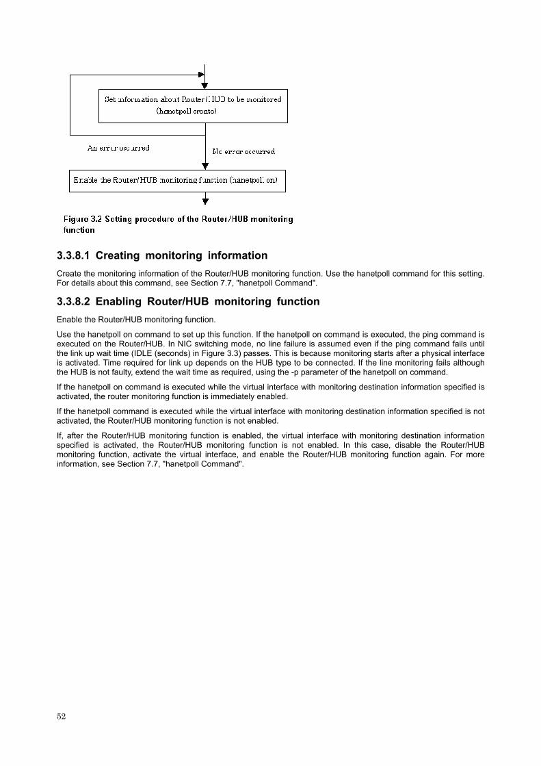
3.3.8.1 Creating monitoring information
Create the monitoring information of the Router/HUB monitoring function. Use the hanetpoll command for this setting. For details about this command, see Section 7.7, "hanetpoll Command".
3.3.8.2 Enabling Router/HUB monitoring function
Enable the Router/HUB monitoring function.
Use the hanetpoll on command to set up this function. If the hanetpoll on command is executed, the ping command is executed on the Router/HUB. In NIC switching mode, no line failure is assumed even if the ping command fails until the link up wait time (IDLE (seconds) in Figure 3.3) passes. This is because monitoring starts after a physical interface is activated. Time required for link up depends on the HUB type to be connected. If the line monitoring fails although the HUB is not faulty, extend the wait time as required, using the -p parameter of the hanetpoll on command.
If the hanetpoll on command is executed while the virtual interface with monitoring destination information specified is activated, the router monitoring function is immediately enabled.
If the hanetpoll command is executed while the virtual interface with monitoring destination information specified is not activated, the Router/HUB monitoring function is not enabled.
If, after the Router/HUB monitoring function is enabled, the virtual interface with monitoring destination information specified is activated, the Router/HUB monitoring function is not enabled. In this case, disable the Router/HUB monitoring function, activate the virtual interface, and enable the Router/HUB monitoring function again. For more information, see Section 7.7, "hanetpoll Command".
52

53

3.3.8.3 Setting operation history of interface up/down
Operation history of the interface up/down can be output as a syslog message. Since this message is output at the INFO level, the following setting is needed:
[Setting file]
/etc/syslog.conf
[Settings]
When enabling message output
Add "*.info" information to the setting file. In this setting, messages are output to the /var/adm/messages file.
# #ident "@(#)syslog.conf 1.4 96/10/11 SMI" /* SunOS 5.0 */
#
# Copyright (c) 1991-1993, by Sun Microsystems, Inc.
#
# syslog configuration file.
#
#
*.err;kern.notice;auth.notice /dev/console
54

*.err;kern.debug;daemon.notice;mail.crit;*.info /var/adm/messages
When disabling message output Delete "*.info" information from the setting file.
# #ident "@(#)syslog.conf 1.4 96/10/11 SMI" /* SunOS 5.0 */
#
# Copyright (c) 1991-1993, by Sun Microsystems, Inc.
#
# syslog configuration file.
#
#
*.err;kern.notice;auth.notice /dev/console
*.err;kern.debug;daemon.notice;mail.crit /var/adm/messages
[Setting notification]
After changing the setting file (/etc/syslog.conf), obtain the super-user rights and then issue a reread notification of the definition file to the syslog daemon (syslogd) as shown below:
(1) Example of acquiring the process ID of the syslog daemon
In the following case, 234 becomes the process ID.
# ps -ef | grep syslogd
root 234 1 0 17:19:04 ? 0:00 /usr/sbin/syslogd
(2) SIGHUP transmission
Send SIGHUP to the process (process ID=234 in the above example) obtained in (1).
# kill -HUP 234
[Others]
For details about how to set the system log, see the system online manuals. Because line monitor error messages are output to the log at the ERROR level, there is no need to make any special settings.
3.3.9 Setting communication party monitoring function
Set the function for monitoring whether the communication party for GS/SURE for the operation in GS/SURE linkage mode can communicate. Use the hanetobserv command for this setting. For details about this command, see Section 7.5, "hanetobserv Command". Before making this setting, GS/SURE linkage mode (operation mode "c") must be set.
3.3.10 Setting standby patrol function
3.3.10.1 Setting what to is be monitored
Possible to set a function to monitor the state of a standby interface in non-activated condition when operating NIC switching mode. It is also possible to set an Automatic failback function when a primary interface recovered using a standby patrol function. Use the hanetconfig command to set it. See Section 7.1, "hanetconfig Command" as to how to set it. It is necessary to set a virtual interface of NIC switching mode (an operation mode is either "d" or "e") before this setting.
3.3.10.2 Setting monitoring interval Set the monitoring interval for the standby NIC. Use the hanetparam command for this setting. For details about this command, see Section 7.6, "hanetparam Command".
3.3.10.3 Setting error monitoring interval Set the monitoring failure count for the standby NIC before a message is output. Use the hanetparam command for this setting. For details about this command, see Section 7.6, "hanetparam Command".
55

3.3.11 Setting dynamic addition/deletion/switching function of real interfaces
In the configuration information defined in Fast switching mode, the number of real interfaces bundled while a virtual interface is active (dynamic) can be changed.
In NIC switching mode, a real interface for the currently operating system can be manually switched to a real interface for the standby system.
3.3.11.1 Dynamic addition of real interfaces
In Fast switching mode, bundled real interfaces can be added while a virtual interface is active (dynamic). Use the hanetnic command for this setting. For details about this command, see Section 7.9, "hanetnic command".
3.3.11.2 Dynamic deletion of real interfaces
In Fast switching mode, bundled real interfaces can be deleted while a virtual interface is active (dynamic). Use the hanetnic command for this setting. For details about this command, see Section 7.9, "hanetnic Command".
3.3.11.3 Dynamic switching of real interfaces
Real interfaces used in a virtual interface in NIC switching mode can be switched while they are active (dynamic), with those of the standby system. Use the hanetnic command for this setting. For details about this command, see Section 7.9, "hanetnic command".
3.3.12 Setting user command execution function
In NIC switching mode and GS/SURE linkage mode, a command pre-defined by a user can be executed at specific timing. For information on execution timing, see Section 2.2.13, "User command execution function". In NIC switching mode, this function can be used to flush an ARP table, change the interface status, etc. In GS/SURE linkage mode, this function can be used to send a signal to a specific process, etc. The following settings must be made to execute a user command. See the sample files for information on creating a script file appropriate for a user's environment.
Sample file for NIC switching mode
/etc/opt/FJSVhanet/script/interface/sha.sam
Sample file for GS/SURE linkage mode
/etc/opt/FJSVhanet/script/host/host.sam
[Setup files]
The storage destination and file name of a setup file varies depending on the type and name of a virtual interface.
Setup file for NIC switching mode
/etc/opt/FJSVhanet/script/interface/shaX
* shaX is the created virtual interface name for NIC switching mode.
Setup file for GS/SURE linkage mode
/etc/opt/FJSVhanet/script/host/hostIP
* hostIP is the host name or IP address of the virtual interface of the communication party.
3.3.12.1 Settings for NIC switching mode
The following shows the script file call format and the definition file sample for the operation in NIC switching mode.
[Script file call format]
/bin/sh shaX param1 param2 param3
param1 activate: Activated inactivate: Inactivated
param2 before: Before activation or deactivation after: After activation or deactivation
56

param3 ifname: Physical interface name
[Definition file sample]
#!/bin/sh
#
# All Rights Reserved, Copyright (c) FUJITSU LIMITED 2001
#
#ident "%W% %G% %U% - FUJITSU"
#
#
# Control interface for HA-Net
#
#
# Params
#
# $1 activate or inactivate
# $2 before or after
# $3 physical interface name
#
#
# Set Params
#
#INTERFACE=$3
#IP_ADDR1="xx.xx.xx.xx"
#IP_ADDR2="yy.yy.yy.yy"
#MAC_ADDR1="xx:xx:xx:xx:xx:xx"
#MAC_ADDR2="yy:yy:yy:yy:yy:yy"
case "$1" in
'activate')
#
# Activate interface
#
case "$2" in
'before')
#
# script before activate interface
57
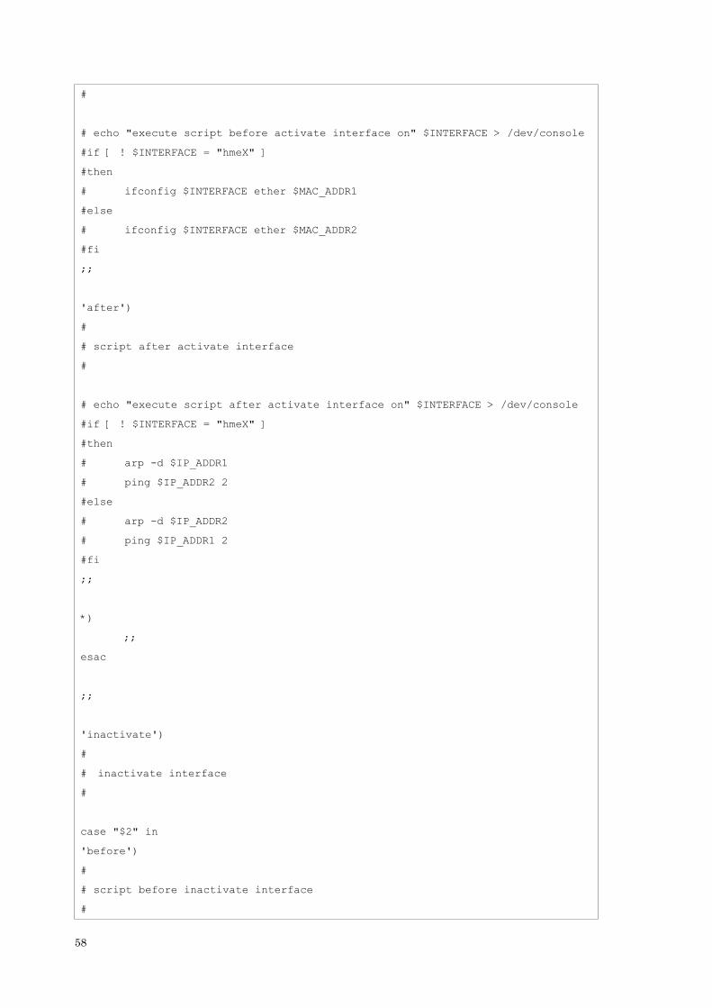
#
# echo "execute script before activate interface on" $INTERFACE > /dev/console
#if [ ! $INTERFACE = "hmeX" ]
#then
# ifconfig $INTERFACE ether $MAC_ADDR1
#else
# ifconfig $INTERFACE ether $MAC_ADDR2
#fi
;;
'after')
#
# script after activate interface
#
# echo "execute script after activate interface on" $INTERFACE > /dev/console
#if [ ! $INTERFACE = "hmeX" ]
#then
# arp -d $IP_ADDR1
# ping $IP_ADDR2 2
#else
# arp -d $IP_ADDR2
# ping $IP_ADDR1 2
#fi
;;
*)
;;
esac
;;
'inactivate')
#
# inactivate interface
#
case "$2" in
'before')
#
# script before inactivate interface
#
58
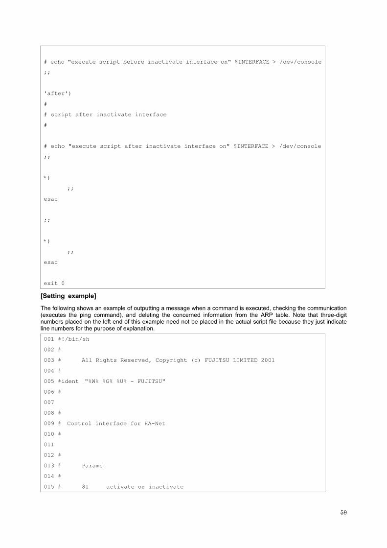
# echo "execute script before inactivate interface on" $INTERFACE > /dev/console
;;
'after')
#
# script after inactivate interface
#
# echo "execute script after inactivate interface on" $INTERFACE > /dev/console
;;
*)
;;
esac
;;
*)
;;
esac
exit 0
[Setting example]
The following shows an example of outputting a message when a command is executed, checking the communication (executes the ping command), and deleting the concerned information from the ARP table. Note that three-digit numbers placed on the left end of this example need not be placed in the actual script file because they just indicate line numbers for the purpose of explanation.
001 #!/bin/sh
002 #
003 # All Rights Reserved, Copyright (c) FUJITSU LIMITED 2001
004 #
005 #ident "%W% %G% %U% - FUJITSU"
006 #
007
008 #
009 # Control interface for HA-Net
010 #
011
012 #
013 # Params
014 #
015 # $1 activate or inactivate
59
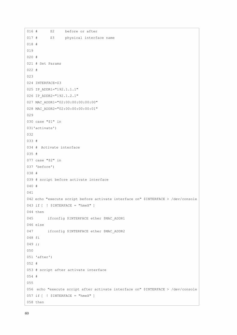
016 # $2 before or after
017 # $3 physical interface name
018 #
019
020 #
021 # Set Params
022 #
023
024 INTERFACE=$3
025 IP_ADDR1="192.1.1.1"
026 IP_ADDR2="192.1.2.1"
027 MAC_ADDR1="02:00:00:00:00:00"
028 MAC_ADDR2="02:00:00:00:00:01"
029
030 case "$1" in
031'activate')
032
033 #
034 # Activate interface
035 #
077 case "$2" in
037 'before')
038 #
039 # script before activate interface
040 #
041
042 echo "execute script before activate interface on" $INTERFACE > /dev/console
043 if [ ! $INTERFACE = "hmeX" ]
044 then
045 ifconfig $INTERFACE ether $MAC_ADDR1
046 else
047 ifconfig $INTERFACE ether $MAC_ADDR2
048 fi
049 ;;
050
051 'after')
052 #
053 # script after activate interface
054 #
055
056 echo "execute script after activate interface on" $INTERFACE > /dev/console
057 if [ ! $INTERFACE = "hmeX" ]
058 then
60

059 arp -d $IP_ADDR1
060 ping $IP_ADDR2 2
061 else
062 arp -d $IP_ADDR2
063 ping $IP_ADDR1 2
064 fi
065 ;;
066 *)
067 ;;
068 esac
069
070 ;;
071
072 'inactivate')
073 #
074 # inactivate interface
075 #
076
077 case "$2" in
078 'before')
079 #
080 # script before inactivate interface
081 #
082
083 echo "execute script before inactivate interface on" $INTERFACE > /dev/console
084 ;;
085
086 'after')
087 #
088 # script after inactivate interface
089 #
090
091 echo "execute script after inactivate interface on" $INTERFACE > /dev/console
092 ;;
093
094 *)
095 ;;
096 esac
097
098 ;;
099
100 *)
101 ;;
61

102 esac
103
104 exit 0
The following explains this setting example. In the explanation, [xxx] represents a line number in this setting example.
[031-071]: Describe the processing of activating the interface.
[042-050]: Outputs a message that a command is executed and sets the interface information (MAC address) depending on the interface type to be processed before the interface is activated.
[056-064]: Outputs a message that a command is executed, deletes the concerned ARP information after the interface is activated, and checks the communication.
[072-099]: Describe the processing of inactivating the interface.
[083-084]: Outputs a message that a command is executed before the interface is inactivated.
[090-092]: Outputs a message that a command is executed after the interface is inactivated.
3.3.12.2 Settings for GS/SURE linkage mode
The following shows the script file call format and the definition file sample for the operation in GS/SURE linkage mode.
[Script file call format]
/bin/sh hostIP
[Definition file sample]
#
# All Rights Reserved, Copyright (c) FUJITSU LIMITED 2001
#
#ident "%W% %G% %U% - FUJITSU"
#
#
# Control interface for HA-Net
#
#
# Set Params
#
#PROC="process_name"
#
# Procedure
#
#
#kill -15 `/usr/bin/ps -e | /usr/bin/sed -n ¥
# -e'/'$PROC'$/s/[^0-9 ¥t].*//p' ¥
# > /dev/null 2>/dev/null
#
62

[Setting example]
The following shows an example of sending a signal (SIGHUP) to the DUMY process. Note that three-digit numbers placed on the left end of this example need not be placed in the actual script file because they just indicate line numbers for the purpose of explanation.
001 #
002 # All Rights Reserved, Copyright (c) FUJITSU LIMITED 2001
003 #
004 #ident "%W% %G% %U% - FUJITSU"
005 #
006
007 #
008 # Control interface for HA-Net
009 #
010
011 #
012 # Set Params
013 #
014
015 PROC="DUMY"
016
017 #
018 # Procedure
019 #
020
020 #
030 kill -1 `/usr/bin/ps -e | /usr/bin/sed -n ¥
-e'/'$PROC'$/s/[^0-9 ¥t].*//p' ¥
> /dev/null 2>/dev/null
The following explains this setting example. In the explanation, [xxx] represents a line number in this setting example.
[015]: Specifies a process name to be stopped.
[030]: Acquires the process ID of a concerned process from the process list and send SIGTERM for the process.
63

64
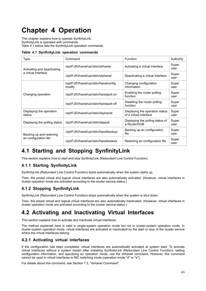
Chapter 4 Operation
This chapter explains how to operate SynfinityLink. SynfinityLink is operated with commands. Table 4.1 below lists the SynfinityLink operation commands.
Table 4.1 SynfinityLink operation commands
Type Command Function Authority
/opt/FJSVhanet/usr/sbin/strhanet Activating a virtual interface Super user Activating and deactivating
a virtual interface /opt/FJSVhanet/usr/sbin/stphanet Deactivating a virtual interface Super
user
/opt/FJSVhanet/usr/sbin/hanetconfig modify
Changing configuration information
Super user
/opt/FJSVhanet/usr/sbin/hanetpoll on Enabling the router polling function
Super user Changing operation
/opt/FJSVhanet/usr/sbin/hanetpoll off Disabling the router polling function
Super user
Displaying the operation status /opt/FJSVhanet/usr/sbin/dsphanet Displaying the operation status
of a virtual interface Super user
Displaying the polling status /opt/FJSVhanet/usr/sbin/dsppoll Displaying the polling status of a Router/HUB
Super user
/opt/FJSVhanet/usr/sbin/hanetbackup Backing up an configuration file
Super user Backing up and restoring
an configuration file /opt/FJSVhanet/usr/sbin/hanetrestore Restoring an configuration file Super
user
4.1 Starting and Stopping SynfinityLink
This section explains how to start and stop SynfinityLink (Redundant Line Control Function).
4.1.1 Starting SynfinityLink
SynfinityLink (Redundant Line Control Function) starts automatically when the system starts up.
Then, the preset virtual and logical virtual interfaces are also automatically activated. (However, virtual interfaces in cluster operation mode are activated according to the cluster service status.)
4.1.2 Stopping SynfinityLink
SynfinityLink (Redundant Line Control Function) stops automatically when the system is shut down.
Then, the preset virtual and logical virtual interfaces are also automatically inactivated. (However, virtual interfaces in cluster operation mode are activated according to the cluster service status.)
4.2 Activating and Inactivating Virtual Interfaces
This section explains how to activate and inactivate virtual interfaces.
The method explained here is valid in single-system operation mode but not in cluster-system operation mode. In cluster-system operation mode, virtual interfaces are activated or inactivated by the start or stop of the cluster service where the virtual interfaces belong.
4.2.1 Activating virtual interfaces
If the configuration has been completed, virtual interfaces are automatically activated at system start. To activate virtual interfaces without a system restart after installing SynfinityLink (Redundant Line Control Function), setting configuration information, and specifying an operation mode, use the strhanet command. However, this command cannot be used in virtual interfaces in NIC switching mode (operation mode "d" or "e").
For details about this command, see Section 7.2, "strhanet Command".
65

4.2.2 Inactivating virtual interfaces
Virtual interfaces are automatically inactivated at system shutdown. To inactivate virtual interfaces without a system restart, use the stphanet command. However, this command cannot be used in virtual interfaces in NIC switching mode (operation mode "d" or "e").
For details about this command, see Section 7.3, "stphanet command".
4.3 Displaying Operation Status
Use the dsphanet command to display the operation status of virtual interfaces.
Specifying options enables the display of the operation status of specific virtual interfaces, the operation status of communication parties in Fast switching mode, and the number of connections to be assigned in GS linkage mode. For details about this command, see Section 7.4, "dsphanet Command".
4.4 Displaying Monitoring Status
Use the dsppoll command to display the monitoring statuses of the router/HUB function and the communication party monitoring function.
For information on this command, see Section 7.8, "dsppoll Command".
4.5 Recovery Procedure from Line Failure
This section explains the recovery procedure in various modes after a line failure has occurred.
4.5.1 Recovery procedure from line failure in fast switching mode
No special operation is required because recovery is automatically made after a line failure has occurred.
However, some applications may need to be restarted.
4.5.2 Recovery procedure from line failure in RIP mode
The following shows the recovery procedure from a line failure in RIP mode.
Some applications may need to be restarted after the recovery procedure on SynfinityLink (Redundant Line Control Function).
# /opt/FJSVhanet/usr/sbin/hanetpoll off # /opt/FJSVhanet/usr/sbin/hanetpoll on
4.5.3 Recovery procedure from line failure in fast switching/RIP mode
For information on the recovery procedure from a line failure in fast switching/RIP mode, see Sections 4.5.1, "Recovery procedure from line failure in fast switching mode" and 4.5.2, "Recovery procedure from line failure in RIP mode".
4.5.4 Recovery procedure from line failure in NIC switching mode
The following shows the recovery procedure from a line failure in NIC switching mode.
Some applications may need to be restarted after the recovery procedure on SynfinityLink (Redundant Line Control Function).
[One-system (currently active NIC) failure]
After line recovery, execute the following command:
# /opt/FJSVhanet/usr/sbin/hanetnic change -n shaX
* shaX is the virtual interface name for NIC switching mode.
[Both-system (currently active and standby NICs) failure]
After line recovery, execute the following command:
# /opt/FJSVhanet/usr/sbin/hanetpoll off # /opt/FJSVhanet/usr/sbin/hanetpoll on
66
4.5.5 Recovery procedure from line failure in GS/SURE linkage mode
No special operation is required because recovery is automatically made after a line failure has occurred.
However, some applications may need to be restarted.
4.6 Backing up and Restoring Configuration Files
This section explains how to back up and restore configuration files of SynfinityLink (Redundant Line Control Function).
4.6.1 Backing up Configuration Files
Use the hanetbackup command to back up configuration files.
For details about this command, see Section 7.12, "hanetbackup Command".
4.6.2 Restoring Configuration Files
Use the hanetrestore command to restore configuration files.
For details about this command, see Section 7.13, "hanetrestore Command".
After executing this command, restart the system immediately. The correct operation of SynfinityLink (Redundant Line Control Function) cannot be assured if the system is not restarted.
67

68

Chapter 5 Operation on Cluster System
This chapter explains how to operate SynfinityLink (Redundant Line Control Function) on cluster system.
5.1 Outline of Cluster System Support
In cluster system, SynfinityLink (Redundant Line Control Function) supports the following connection states:
- Active Standby (1:1 and N:1) - Mutual standby
Only a logical IP address (takeover address) allocated to a virtual interface can be taken over. (No MAC addresses or system node names are taken over.) Physical interfaces used by the virtual interface cannot be set as objects of takeover (MAC address or IP address).
When takeover address is taken over, the logical virtual interface defined in the configuration information is also taken over. At this time, it is not possible to set a physical interface that a virtual interface uses as a target of taking over by SynfinityCluster (a MAC address, an IP address).
Figure 5.1 shows an example of address takeover in a virtual device.
5.1.1 Active Standby
5.1.1.1 Switching operation
During normal operation, the system communicates with the remote system using SynfinityLink (Redundant Line Control Function) on the active node.
If a failure (panic, hang-up, or line failure) occurs on the active node, SynfinityLink (Redundant Line Control Function) switches the resources to the standby node. Then, applications make reconnection to take over the communication from the active node.
5.1.1.1.1 Switching operation in Fast switching mode
Figure 5.2 shows the active standby configuration diagram of duplicated operation in fast switching mode. In the figure, the takeover virtual interface (sha0:65) is activated on active node A. If switching occurs due to a failure, the takeover virtual interface (sha0:65) is inactivated on active node A. Then, on standby node B, the takeover virtual interface (sha0:65) is activated on the already activated virtual interface (sha0). Thus, the virtual interface (sha0) on node A does not change statuses.
69

5.1.1.1.2 Switching operation in RIP mode
Figure 5.3 shows the active standby configuration diagram of duplicated operation in RIP mode. In the figure, the takeover virtual interface (sha0:65) is activated on active node A. If switching occurs due to a failure, the takeover virtual interface (sha0:65) and the virtual interface (sha0) are inactivated on node A. Then, on standby node B, the virtual interface (sha0) and the takeover virtual interface (sha0:65) are activated.
70

5.1.1.1.3 Switching operation in NIC switching mode
NIC switching mode has the following functions. Select a function to be used depending on your operation.
- Logical address takeover function Use the logical address takeover function to use a LAN in NIC switching mode both for jobs and management. In this case, communication is performed using a logical IP address for jobs and a physical IP address for management. For the remote system device to make a connection, a physical IP address should be specified as the connection address. Then, the remote system device can directly connect to the active or standby node and manage each of the nodes regardless of the status transition of the cluster service. For this function, two IP addresses are assigned to one physical interface. To use a TCP/IP application that requires only one IP address to be specified, use the physical address takeover function I or II.
- Physical IP address takeover function I Use the physical IP address takeover function I to use a LAN in NIC switching mode both for jobs and management and specify only one IP address for one physical interface. As for the logical address takeover function, this function allows a connection to be made for each of the active and standby nodes independently. However, IP address of the standby node changes according to the status transition of the cluster service. Thus, when clusters are switched, the TCP connection to the standby node is cleared. For the communication party device to make a connection again, the connection IP address must be changed.
- Physical IP address takeover function II Use the physical IP address takeover function II to use a LAN in NIC switching mode only for jobs. In this case, no connection can be made to the standby node because the LAN of the standby node is inactivated. Another LAN must be provided to make a connection.
Figure 5.4 shows the active standby configuration diagram of duplicated operation in NIC switching mode (logical IP address takeover function). The operation in this figure is as follows: On active node A, the logical interface (hme1:1) of the secondary interface (hme1) is assigned the takeover virtual IP address (IP-A) and activated. If switching occurs due to a failure, the takeover virtual interface (hme1:1) that has been assigned the takeover IP address (IP-A) is inactivated. Then, on standby node B, the logical interface (hme0:1) that has been assigned the takeover IP address (IP-A) on the already activated primary interface (hme0) is activated.
71

Figure 5.5 shows the active standby configuration diagram of duplicated operation in NIC switching mode (physical IP address takeover function I). (The physical IP address takeover function I activates a real NIC on the standby node.) The operation in this figure is as follows: On active node A, the takeover virtual IP address (IP-A) is assigned the secondary interface (hme1) and activated. If switching occurs due to a failure, the already activated primary interface (hme0) on standby node B is first inactivated, assigned the takeover IP address (IP-A), and activated again. Then, on node A now in standby status, the secondary interface (hme1) that has been assigned the takeover IP address (IP-A) is assigned another IP address (IP-1) and activated again.
72

Figure 5.6 shows the active standby configuration diagram of duplicated operation in NIC switching mode (physical IP address takeover function II). (The physical IP address takeover function II does not activate a real NIC on the standby node.) The operation in this figure is as follows: On active node A, the takeover virtual IP address (IP-A) is assigned the secondary interface (hme1) and activated. If switching occurs due to a failure, the already activated primary interface (hme0) on standby node B is assigned the takeover IP address (IP-A) and activated. Then, on node A now in standby status, the secondary interface (hme1) that has been assigned the takeover IP address (IP-A) is inactivated.
73

5.1.1.1.4 Switching operation in GS/SURE linkage mode
Figure 5.7 shows the active standby configuration diagram of duplicated operation in GS/SURE linkage mode. In the figure, the takeover virtual interface (sha0:65) is activated on active node A. If switching occurs due to a failure, the takeover virtual interface (sha0:65) and the virtual interfaces (sha0, sha1, and sha2) are inactivated on node A. Then, the real interfaces (hme0 and hme1) are activated by the IP addresses that has been assigned to the virtual interfaces (sha1 and sha2). On standby node B, the real interfaces (hme0 and hme1) are inactivated and the virtual interfaces (sha1 and sha2) are activated. Then, the virtual interface (sha0) that bundles the virtual interfaces (sha1 and sha2) as well as the takeover virtual interface (sha0:65) are activated.
74
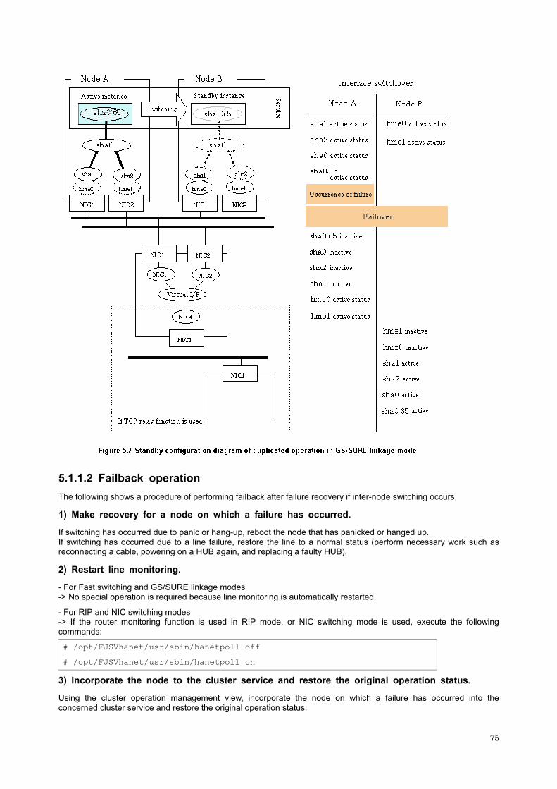
5.1.1.2 Failback operation
The following shows a procedure of performing failback after failure recovery if inter-node switching occurs.
1) Make recovery for a node on which a failure has occurred.
If switching has occurred due to panic or hang-up, reboot the node that has panicked or hanged up. If switching has occurred due to a line failure, restore the line to a normal status (perform necessary work such as reconnecting a cable, powering on a HUB again, and replacing a faulty HUB).
2) Restart line monitoring.
- For Fast switching and GS/SURE linkage modes -> No special operation is required because line monitoring is automatically restarted.
- For RIP and NIC switching modes -> If the router monitoring function is used in RIP mode, or NIC switching mode is used, execute the following commands:
# /opt/FJSVhanet/usr/sbin/hanetpoll off # /opt/FJSVhanet/usr/sbin/hanetpoll on
3) Incorporate the node to the cluster service and restore the original operation status.
Using the cluster operation management view, incorporate the node on which a failure has occurred into the concerned cluster service and restore the original operation status.
75

5.1.2 Mutual standby
5.1.2.1 Switching operation
Define more than one virtual interface and set the resources as separate services to enable mutual standby operation. During normal operation, the system communicates with the remote system using a virtual interface on the active instance of each service. If a failure (panic, hang-up, or line failure) occurs on the active instance, the standby instance takes over the virtual interface included in the active instance. Then, applications make reconnection to take over the communication from the active instance.
5.1.2.1.1 Switching operation in Fast switching mode
Figure 5.8 shows the mutual standby configuration diagram of duplicated operation in Fast switching mode. The takeover of an address, etc. is performed in the same way as for the active standby configuration. For information, see Section 5.1.1.1.1, "Switching operation in Fast switching mode".
5.1.2.1.2 Switching operation in RIP switching mode
Figure 5.9 shows the mutual standby configuration diagram of duplicated operation in RIP switching mode. The takeover of an address, etc. is performed in the same way as for the active standby configuration. For information, see Section 5.1.1.1.2, "Switching operation in RIP mode".
76

5.1.2.1.3 Switching operation in NIC switching mode
Figure 5.10 shows the mutual standby configuration diagram in NIC switching mode (without NIC sharing). The takeover of an address, etc. is performed in the same way as for the active standby configuration. For information, see Section 5.1.1.1.3, "Switching operation in NIC switching mode".
77
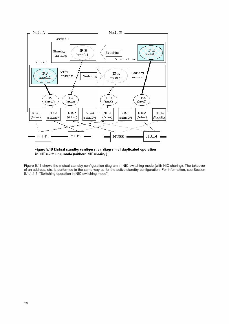
Figure 5.11 shows the mutual standby configuration diagram in NIC switching mode (with NIC sharing). The takeover of an address, etc. is performed in the same way as for the active standby configuration. For information, see Section 5.1.1.1.3, "Switching operation in NIC switching mode".
78

5.1.2.1.4 Switching operation in GS/SURE linkage mode
Figure 5.12 shows the mutual standby configuration diagram of duplicated operation in GS/SURE linkage mode. The takeover of an address, etc. is performed in the same way as for the active standby configuration. For information, see Section 5.1.1.1.4, "Switching operation in GS/SURE linkage mode".
79

5.1.2.2 Failback operation
The failback is performed in the same way as for the active standby configuration. For information, see Section 5.1.1.2, "Failback operation".
5.1.3 Notes
- If a node name needs to be taken over, do it in the following way: -- Use the clsetnodename command so that the system node name of both nodes matches the host name of /etc/inet/hosts corresponding to the virtual IP of SynfinityLink (Redundant Line Control Function). The node name can be taken over only in the event of system configuration, as in the case of a 1:1 active standby system configuration. When this setting is made, do not make any node name takeover setting from the cluster management view.
80

- When using SynfinityCluster 2.0 or later, occasionally a virtual interface (shaX) is output to the resource information of the interface, That is output to a management view of the cluster operation. Never use this virtual interface in other than SynfinityLink.
- When communicating with a machine on another network using a virtual interface of Fast switching mode, It is necessary to change the timing to activate a virtual interface with the "-t init" option of the habetparam command. See Section 7.6, "hanetparam Command" for the detail.
5.2 Adding configuration for Cluster System
To run SynfinityLink (Redundant Line Control Function), you must not only set up the ordinary configuration but also create configuration information and register resources for cluster system. Figure 5.11 shows the flowchart for adding the cluster configuration. For an operation in the mutual standby mode, repeat the procedure described below.
SynfinityLink provides commands for defining cluster operations. To execute these commands, cluster system must be installed in the system.
Table 5.1 lists the cluster definition operation commands.
Table 5.1 Cluster definition operation commands
Type Command Function Authority
/opt/FJSVhanet/sys/claddhanetrsc -n devicename
Registering a virtual interface in resources
Super user Registering and Deleting
virtual interface /opt/FJSVhanet/sys/cldelhanetrsc -n devicename
Deleting a virtual interface in resources
Super user
/opt/FJSVhanet/sys/claddhanetiprsc -n devicename -i ip_address
Registering a takeover IP address in resources
Super user Registering and Deleting
takeover IP address /opt/FJSVhanet/sys/cldelhanetiptrc -n resource-name
Deleting a takeover IP address in resources
Super user
/opt/FJSVhanet/sys/claddhanetsvc -n devicename
To register the service resource
Super user Registering and Deleting
service resource /opt/FJSVhanet/sys/cldelhanetsvc -n devicename
To delete the service resource
Super user
5.2.1 Creating configuration information
Create the necessary configuration information for constructing a virtual interface. The information must be created on both the active and standby nodes. For details about the creation procedure, see Chapter 3, "Installation."
81
5.2.2 Registering resources for virtual interfaces
Register resources for virtual interfaces. The resources must be registered on both the active and standby nodes. The following shows an example. For information on the commands, see Section 7.14, "claddhanetrsc Command".
[Resource registration]
- Registering a takeover address in resources
# /opt/FJSVhanet/sys/claddhanetrsc -n "virtual-interface-name"
5.2.3 Setting takeover IP address resource
Set a takeover IP address for a virtual interface. This setting must be made on either the active or standby node. The following shows some setting examples.
To make a setting in NIC switching mode (operation mode "d" or "e"), you need not set "-i takeover-address". "-k key" specifies the resource key of a shared resource to be registered. A resource key specified in this option is used as the resource name. This option may be omitted. If this option is omitted, a takeover IP address specified in the -i option is used as the resource key.
For information on the command, see Section 7.15, "claddhanetiprsc Command".
[Setting a takeover address (other than NIC switching mode (operation mode "d" or "e"))]
# /opt/FJSVhanet/sys/claddhanetrsc -n "virtual-interface-name" -i "takeover-address" [-k "resource-key"]
As the takeover address, specify either an IP address with a different host section or a host name that has the same subnet as the virtual IP address defined in the configuration information.
[Setting a takeover address (NIC switching mode (operation mode "d" or "e")]
# /opt/FJSVhanet/sys/claddhanetrsc -n "virtual-interface-name" [-k "resource-key"]
As the takeover address, the virtual IP address defined in "-i" in the configuration information is automatically set.
5.2.4 Setting service resource
Add a takeover IP address to a cluster service.
This setting must be made on either the active or standby node. The following shows some setting examples. Before setting a cluster service, you must define a cluster service name from the cluster operation management view. As the "resource to be set" in the cluster service name, specify a takeover IP address specified in the takeover address setting or a character string specified in the "-k" option.
For information on the command, see Section 7.16, "claddhanetsvc Command".
[Setting a service]
# /opt/FJSVhanet/sys/claddhanetsvc -n "virtual-interface-name"
5.2.5 Restarting the system
Restart the systems on both nodes.
5.2.6 Notes
In GS/SURE linkage mode, the time on the nodes in a cluster system need to be synchronized. Communication may fail if the time on the nodes is not synchronized.
No takeover address can be defined from the cluster management view. You need to perform the procedure described in Section 5.2.3, "Setting takeover IP address resource".
No takeover IP address can be added to the cluster service from the cluster management view. You need to perform the procedure described in Section 5.2.4, "Setting service resource".
Before setting a service, you must define a cluster service name from the cluster operation management view.
If a virtual interface is added to a cluster service, all the nodes that make up the cluster must be restarted.
A virtual interface with the same name must be created on the active and standby nodes.
82

Execute the "/etc/opt/FJSVcluster/sys/clautoconfig" command provided by the cluster system if the real interface to be used for SynfinityLink does not exist among the cluster resources (i.e., the "/etc/opt/FJSVcluster/bin/clgettree" command does not display a real interface name (such as hme0 and qfe0)).
To use GS/SURE linkage mode, you are recommended to set, on the active node, monitoring information for a virtual interface on the standby node and, on the standby node, monitoring information for a virtual interface on the active node. This procedure prevents unnecessary failover.
5.3 Deleting configuration for Cluster System
This section explains a procedure to delete and how to delete a definition of the cluster environment of SynfinityLink (Redundant Line Control Function). Before executing the following procedure, it is necessary to stop a cluster service by a management view of the cluster operation. Figure 5.14 shows a flow of the procedure to delete the cluster environment. When operating in mutual standby mode, repeat the following procedure.
5.3.1 Deleting service resource
Delete the takeover resource address (shared resource) in the service tree of cluster system. The takeover addresses must be deleted in either of the nodes, the active system node or standby system node. An example is below.
[Deleting a service]
# /opt/FJSVhanet/sys/cldelhanetsvc -n "virtual-interface-name"
5.3.2 Deleting resources
(1) Deleting a takeover IP address
Delete resource information for a takeover IP address from the resource database retained by cluster system. Resource information must be deleted in either of the nodes, active system node or standby system node. An example is below. The resource name must be either the IP address specified in the takeover address setting or the character string specified in the "-k" option.
[Deleting a takeover IP address]
# /opt/FJSVhanet/sys/cldelhanetiprsc -k "resource-name"
[Example of confirming resource name for takeover IP address]
# /etc/opt/FJSVcluster/bin/clgettree Cluster 1 cluster Domain 2 Domain0 Shared 7 SHD_Domain0 Psd 8 planpath0 ON SHD_HAnet 63 192.13.78.1 UNKNOWN (※1) Hanet_Ipaddress 61 sha1:65 ON gp7000f Hanet_Ipaddress 62 sha1:65 ON kent
83

84
SHD_FileSystem 73 SHD_FS_Service1 UNKNOWN FileSystem 71 FS_Service1 UNKNOWN kent FileSystem 72 FS_Service1 UNKNOWN gp7000f Node 3 gp7000f ON SystemState2 15 FJSVclprt_spool UNKNOWN DISK 18 c0t0d0 UNKNOWN HAnet 59 sha1 ON HAnet_Ipaddress 61 sha1:65 ON FileSystem 72 FS_Service1 UNKNOWN Node 5 kent ON SystemState2 16 FJSVclprt_spool UNKNOWN Ethernet 21 hme2 UNKNOWN Ethernet 22 hme3 UNKNOWN Ethernet 23 hme4 UNKNOWN DISK 24 c0t0d0 UNKNOWN DISK 25 c1t3d0 UNKNOWN HAnet 60 sha1 ON HAnet_Ipaddress 62 sha1:65 ON FileSystem 71 FS_Service1 UNKNOWN #
*1 Resource ID (172.18.20.1 in the above example)
(2) Deleting virtual interface resource
Delete resource information for virtual interface from the resource database retained by cluster system. Resource information is deleted in both active system node and standby system node. An example is below.
[Deleting a virtual interface resource]
# /opt/FJSVhanet/sys/cldelhanetrsc -n "virtual-interface-name"
5.3.3 Notes
- In a cluster system service that has virtual interface, if the definition for the virtual interface is deleted, all nodes forming that cluster must be rebooted.
- When deleted a cluster definition of a virtual interface in NIC switching mode, be sure to delete the configuration information before restarting a node. Delete the configuration information in the other mode if necessary. See Section 3.2.3, "Deleting configuration information" as to a procedure to delete the configuration information.

Chapter 6 Maintenance
This chapter explains commands and other helpful tools (including parameters) that collect troubleshooting information in the event of a problem in SynfinityLink (Redundant Line Control Function).
6.1 SynfinityLink(Redundant Line Control Function) Troubleshooting Data to be Collected
In the event of a problem in SynfinityLink operation, SynfinityLink troubleshooting requires following information about the problem to be collected.
- Operational steps taken and the relevant error messages
- Console log (/var/adm/messages)
- Results of executing ifconfig -a
- Results of executing netstat -ni
- Results of executing netstat -nr
- Results of executing netstat -np
- Results of executing ipcs -a
- Presence or absence of the /etc/defaultrouter file
- Presence or absence of the /etc/notrouter file
- Settings for ip_forwarding (results of executing ndd -get /dev/ip_forwarding)
- Packet trace (results of executing the snoop command for bundled physical interface) [Example] To collect log data for hme0, execute the snoop command. The following example returns an output of the log in the binary format in a file at directory /var/tmp/log.hme0: snoop -o /var/tmp/log.hme0 -d hme0
- Results of executing traceroute
- Process list (results of executing ps -ef)
- Results of executing /etc/opt/FJSVcluster/bin/clgettree (only in cluster operation)
- Results of executing /etc/opt/FJSVcluster/bin/clgettree -s (only in cluster operation)
- Log file for SynfinityLink (/var/opt/FJSVhanet/log/*)
- Configuration files for SynfinityLink (/etc/hanet.conf and /etc/opt/FJSVhanet/config/*)
- Output of driver trace for SynfinityLink (see Section 6.2, "Trace," for details about collecting this data)
6.2 Trace
This section explains how to collect driver trace for SynfinityLink.
6.2.1 Starting driver trace
[Synopsis]
/opt/FSUNnet/bin/strotr -k sha [-m msize] [-b bsize] [-a]
[Feature description]
Starts the collecting data of SynfinityLink trace logs.
[Options]
You can specify following options:
-k sha
Specifies the type of trace for drivers. Add "sha" to collect the trace for SynfinityLink.
85

-m msize
Specifies the buffer size in kilobytes for collecting the memory trace. The size has a range of 8 to 256 KB. The default value is 8 KB.
-b bsize
Specifies the maximum file size of the log file in kilobytes for collecting the file trace. The size has a range of 8 to 1,000 KB. The default value is 8 KB. Since the trace data is collected in a log file, collecting a larger volume of file trace data than that of memory trace data is possible, but the result is a low processing speed.
-a
Specifies for collecting all of the data. The default assumes that 64 bytes of the data should be collected.
[Related commands]
stpotr prtotr
[Notes]
If both -m option and -b option are not specified, the driver trace is performed as a memory trace. If both -m option and -b option are specified, the processing of the file trace has a higher priority.
[Example]
- The following is an example of collecting the memory trace (when all of the data is to be collected with the trace buffer size for the main memory specified as 256 KB):
# strotr -k sha -m 256 -a
- The following is an example for collecting the file trace (when the maximum size of the log file is specified as 1,000 KB and collecting all of the data is not necessary):
# strotr -k sha -b 1000
6.2.2 Stopping driver trace
[Synopsis]
/opt/FSUNnet/bin/stpotr -k sha
[Feature description]
Stops collecting SynfinityLink trace logging data.
[Option]
You can specify following option:
-k sha
Specifies the type of trace for drivers. Specify the same "sha" (trace type) specified at the start of trace collection.
[Related commands]
strotr prtotr
[Examples]
- The following is an example of stopping the driver trace:
# stpotr -k sha
6.2.3 Outputting driver trace
[Synopsis]
/opt/FSUNnet/bin/prtotr -k sha
86

[Feature description]
Outputs the collected SynfinityLink trace logging data.
[Option]
You can specify following option:
-k sha
Specifies the type of trace for drivers. Specify the same "sha" (trace type) specified at the start of trace collection. If this option is not specified, all collected traces currently in memory are displayed.
[Related commands]
strotr stpotr
[Examples]
- The following is an example of outputting the driver trace:
# prtotr -k sha
6.2.4 Precautions about driver trace function
An operator with the superuser privilege can execute the strotr, stpotr or prtotr commands.
Since the high load on the CPU under trace processing deteriorates performance, trace should be performed sparingly.
A log file is created in the /var/opt/FJSVhanet/otr directory. When specifying the maximum size for the log file with the -b option, be sure to check for available disk space beforehand.
Collecting trace data by running a file trace may lead to a loss of trace data, but this event is rare.
If an invalid option is specified in a command (strotr, stpotr and prtotr commands), only commands with valid options are processed, and commands with invalid options are ignored.
87

88

Chapter 7 Command References
This chapter explains how to use the commands provided by SynfinityLink (Redundant Line Control Function).
7.1 hanetconfig Command
[Name]
hanetconfig - Setting, modifying, deleting, and displaying a configuration definition of SynfinityLink (Redundant Line Control Function)
[Synopsis]
/opt/FJSVhanet/usr/sbin/hanetconfig command [args]
[Feature description]
The hanetconfig command defines configuration information required for the operation of SynfinityLink (Redundant Line Control Function). This command also modifies, deletes, and displays a setting.
Command Process outline Authority
create Creates configuration information Super user
copy Copies configuration information Super user
print Displays configuration information General user
modify Modifies configuration information Super user
delete Deletes configuration information Super user
version Displays the version Super user
(1) create command
Configuration information must be defined for a virtual interface before SynfinityLink (Redundant Line Control Function) can be operated. Use the create command to create a definition of configuration information. The create command can also create definitions of more than one logical virtual interface on the virtual interface. The following is the command format for building a virtual interface:
/opt/FJSVhanet/usr/sbin/hanetconfig create -n devicename
-m {t|r|b|n|c|d|e|p|q} -i ipaddress1 -e ipaddress2
-t interface1[,interface2.....] -a MAC-address
-n devicename:
Specify the name of a virtual interface or logical virtual interface for which the configuration information should be set. Specify the virtual interface name with a string that begins with "sha" and is followed by a value (0 to 255) (such as sha0 and sha10). Specify the logical virtual interface name as "virtual-interface-name: value (2 to 64)" (such as sha0:2 and sha10:5). If you specify a virtual interface or logical virtual interface in any other format, an error message is output and this command terminates abnormally.
-m t|r|b|n|c|d|e|p|q:
Specify an operation mode. If devicename is a logical virtual interface, specify the operation mode of a corresponding virtual interface.
t: Fast switching mode Specify this parameter to use the Redundant Line Control Function in Fast switching mode.
r: RIP mode Specify this parameter to use the Redundant Line Control Function in RIP mode.
b: Fast switching/RIP mode Specify this parameter to use the Redundant Line Control Function in Fast switching/RIP mode.
n: GS/SURE linkage mode (real interface definition) Specify this parameter to use the Redundant Line Control Function in GS/SURE linkage mode. A real interface used to actually perform communication is created.
89
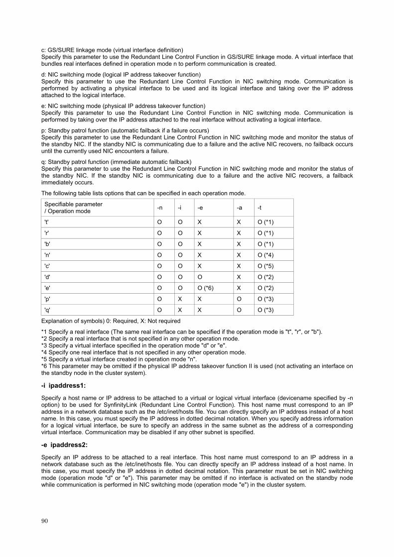
c: GS/SURE linkage mode (virtual interface definition) Specify this parameter to use the Redundant Line Control Function in GS/SURE linkage mode. A virtual interface that bundles real interfaces defined in operation mode n to perform communication is created.
d: NIC switching mode (logical IP address takeover function) Specify this parameter to use the Redundant Line Control Function in NIC switching mode. Communication is performed by activating a physical interface to be used and its logical interface and taking over the IP address attached to the logical interface.
e: NIC switching mode (physical IP address takeover function) Specify this parameter to use the Redundant Line Control Function in NIC switching mode. Communication is performed by taking over the IP address attached to the real interface without activating a logical interface.
p: Standby patrol function (automatic failback if a failure occurs) Specify this parameter to use the Redundant Line Control Function in NIC switching mode and monitor the status of the standby NIC. If the standby NIC is communicating due to a failure and the active NIC recovers, no failback occurs until the currently used NIC encounters a failure.
q: Standby patrol function (immediate automatic failback) Specify this parameter to use the Redundant Line Control Function in NIC switching mode and monitor the status of the standby NIC. If the standby NIC is communicating due to a failure and the active NIC recovers, a failback immediately occurs.
The following table lists options that can be specified in each operation mode.
Specifiable parameter / Operation mode -n -i -e -a -t
't' O O X X O (*1)
'r' O O X X O (*1)
'b' O O X X O (*1)
'n' O O X X O (*4)
'c' O O X X O (*5)
'd' O O O X O (*2)
'e' O O O (*6) X O (*2)
'p' O X X O O (*3)
'q' O X X O O (*3)
Explanation of symbols) 0: Required, X: Not required
*1 Specify a real interface (The same real interface can be specified if the operation mode is "t", "r", or "b"). *2 Specify a real interface that is not specified in any other operation mode. *3 Specify a virtual interface specified in the operation mode "d" or "e". *4 Specify one real interface that is not specified in any other operation mode. *5 Specify a virtual interface created in operation mode "n". *6 This parameter may be omitted if the physical IP address takeover function II is used (not activating an interface on the standby node in the cluster system).
-i ipaddress1:
Specify a host name or IP address to be attached to a virtual or logical virtual interface (devicename specified by -n option) to be used for SynfinityLink (Redundant Line Control Function). This host name must correspond to an IP address in a network database such as the /etc/inet/hosts file. You can directly specify an IP address instead of a host name. In this case, you must specify the IP address in dotted decimal notation. When you specify address information for a logical virtual interface, be sure to specify an address in the same subnet as the address of a corresponding virtual interface. Communication may be disabled if any other subnet is specified.
-e ipaddress2:
Specify an IP address to be attached to a real interface. This host name must correspond to an IP address in a network database such as the /etc/inet/hosts file. You can directly specify an IP address instead of a host name. In this case, you must specify the IP address in dotted decimal notation. This parameter must be set in NIC switching mode (operation mode "d" or "e"). This parameter may be omitted if no interface is activated on the standby node while communication is performed in NIC switching mode (operation mode "e") in the cluster system.
90
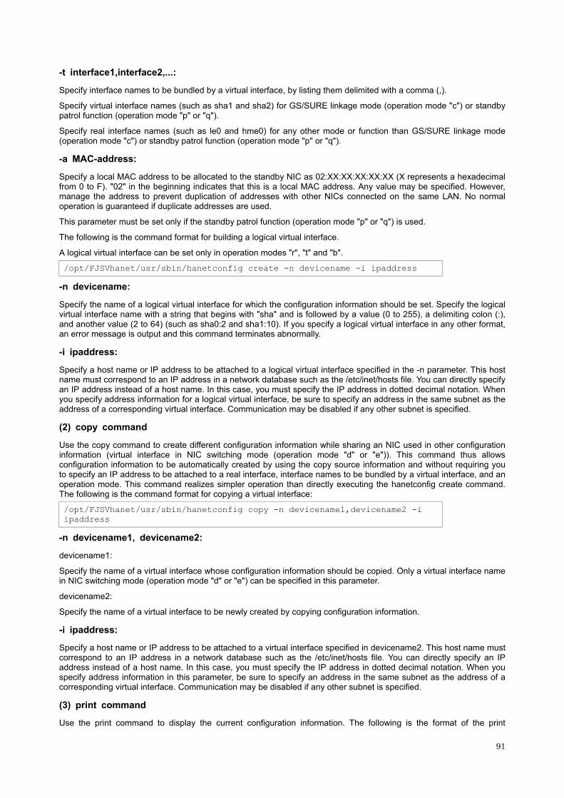
-t interface1,interface2,...:
Specify interface names to be bundled by a virtual interface, by listing them delimited with a comma (,).
Specify virtual interface names (such as sha1 and sha2) for GS/SURE linkage mode (operation mode "c") or standby patrol function (operation mode "p" or "q").
Specify real interface names (such as le0 and hme0) for any other mode or function than GS/SURE linkage mode (operation mode "c") or standby patrol function (operation mode "p" or "q").
-a MAC-address:
Specify a local MAC address to be allocated to the standby NIC as 02:XX:XX:XX:XX:XX (X represents a hexadecimal from 0 to F). "02" in the beginning indicates that this is a local MAC address. Any value may be specified. However, manage the address to prevent duplication of addresses with other NICs connected on the same LAN. No normal operation is guaranteed if duplicate addresses are used.
This parameter must be set only if the standby patrol function (operation mode "p" or "q") is used.
The following is the command format for building a logical virtual interface.
A logical virtual interface can be set only in operation modes "r", "t" and "b".
/opt/FJSVhanet/usr/sbin/hanetconfig create -n devicename -i ipaddress
-n devicename:
Specify the name of a logical virtual interface for which the configuration information should be set. Specify the logical virtual interface name with a string that begins with "sha" and is followed by a value (0 to 255), a delimiting colon (:), and another value (2 to 64) (such as sha0:2 and sha1:10). If you specify a logical virtual interface in any other format, an error message is output and this command terminates abnormally.
-i ipaddress:
Specify a host name or IP address to be attached to a logical virtual interface specified in the -n parameter. This host name must correspond to an IP address in a network database such as the /etc/inet/hosts file. You can directly specify an IP address instead of a host name. In this case, you must specify the IP address in dotted decimal notation. When you specify address information for a logical virtual interface, be sure to specify an address in the same subnet as the address of a corresponding virtual interface. Communication may be disabled if any other subnet is specified.
(2) copy command
Use the copy command to create different configuration information while sharing an NIC used in other configuration information (virtual interface in NIC switching mode (operation mode "d" or "e")). This command thus allows configuration information to be automatically created by using the copy source information and without requiring you to specify an IP address to be attached to a real interface, interface names to be bundled by a virtual interface, and an operation mode. This command realizes simpler operation than directly executing the hanetconfig create command. The following is the command format for copying a virtual interface:
/opt/FJSVhanet/usr/sbin/hanetconfig copy -n devicename1,devicename2 -i ipaddress
-n devicename1, devicename2:
devicename1:
Specify the name of a virtual interface whose configuration information should be copied. Only a virtual interface name in NIC switching mode (operation mode "d" or "e") can be specified in this parameter.
devicename2:
Specify the name of a virtual interface to be newly created by copying configuration information.
-i ipaddress:
Specify a host name or IP address to be attached to a virtual interface specified in devicename2. This host name must correspond to an IP address in a network database such as the /etc/inet/hosts file. You can directly specify an IP address instead of a host name. In this case, you must specify the IP address in dotted decimal notation. When you specify address information in this parameter, be sure to specify an address in the same subnet as the address of a corresponding virtual interface. Communication may be disabled if any other subnet is specified.
(3) print command
Use the print command to display the current configuration information. The following is the format of the print
91

command.
/opt/FJSVhanet/usr/sbin/hanetconfig print [ -n devicename1,devicename2...]
-n devicename1,devicename2...:
Specify the name of a virtual interface or logical virtual interface whose configuration information should be displayed. If this option is not specified, the print command displays all the configuration information for the currently set virtual interfaces and logical virtual interfaces.
The following shows an example of displaying configuration information.
Name Hostname Mode MAC Adder/Phys ip Interface List
+-----------+---------------+----+-----------------+-------------------+
sha0 hostA t hme0,hme1
sha1 10.0.1.1 r hme0,hme1
Name: Outputs a virtual interface name.
Hostname: Outputs the host name or virtual IP address of a virtual interface.
Mode: Outputs the operation mode of a virtual interface.
t: Fast switching mode r: RIP mode b: Fast switching/RIP mode n: GS/SURE linkage mode (real interface definition) c: GS/SURE linkage mode (virtual interface definition) d: NIC switching mode (logical IP address takeover function) e: NIC switching mode (physical IP address takeover function) p: Standby patrol function (automatic failback if a failure occurs) q: Standby patrol function (immediate automatic failback)
MAC Adder/Phys ip: Outputs a MAC address defined in standby patrol mode.
Interface List: Outputs a virtual interface name in GS/SURE linkage mode (operation mode "c") or standby patrol function (operation mode "p" or "q"). Outputs a physical interface name (such as le0 and hme0) in any other mode than GS/SURE linkage mode (operation mode "c") or standby patrol function (operation mode "p" or "q").
(4) modify command
Use the modify command to modify the configuration of SynfinityLink (Redundant Line Control Function). The following is the format of the modify command that modifies configuration information for a virtual interface:
/opt/FJSVhanet/usr/sbin/hanetconfig modify -n devicename
{[-m t|r|b]|[-i ipaddress1]|[-e ipaddress2]|
[-t interface1[,interface2.....]]|[-a MAC-address]}
-n devicename:
Specify the name of a virtual interface whose configuration information should be modified. This parameter is required.
-m t|r|b:
Specify this parameter to change the operation mode (Fast switching, RIP, or Fast switching/RIP mode) of a virtual interface to be modified. One of Fast switching, RIP, or Fast switching/RIP mode can be selected (t indicates Fast switching mode, r indicates RIP mode, and b indicates Fast switching/RIP mode).
-i ipaddress1:
Specify a host name or IP address to be attached to a virtual or logical virtual interface (devicename specified by -n option) to be used for SynfinityLink (Redundant Line Control Function). This host name must correspond to an IP address in a network database such as the /etc/inet/hosts file. You can directly specify an IP address instead of a host name. In this case, you must specify the IP address in dotted decimal notation. When you specify address information for a logical virtual interface, be sure to specify an address in the same subnet as the address of a corresponding virtual interface. Communication may be disabled if any other subnet is specified.
92
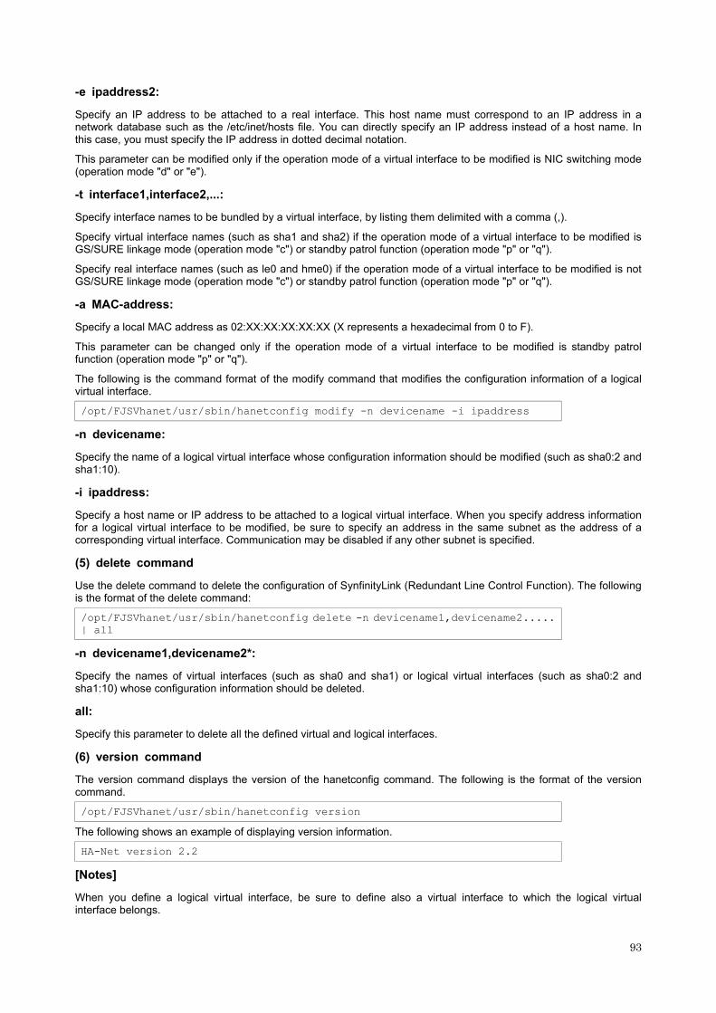
-e ipaddress2:
Specify an IP address to be attached to a real interface. This host name must correspond to an IP address in a network database such as the /etc/inet/hosts file. You can directly specify an IP address instead of a host name. In this case, you must specify the IP address in dotted decimal notation.
This parameter can be modified only if the operation mode of a virtual interface to be modified is NIC switching mode (operation mode "d" or "e").
-t interface1,interface2,...:
Specify interface names to be bundled by a virtual interface, by listing them delimited with a comma (,).
Specify virtual interface names (such as sha1 and sha2) if the operation mode of a virtual interface to be modified is GS/SURE linkage mode (operation mode "c") or standby patrol function (operation mode "p" or "q").
Specify real interface names (such as le0 and hme0) if the operation mode of a virtual interface to be modified is not GS/SURE linkage mode (operation mode "c") or standby patrol function (operation mode "p" or "q").
-a MAC-address:
Specify a local MAC address as 02:XX:XX:XX:XX:XX (X represents a hexadecimal from 0 to F).
This parameter can be changed only if the operation mode of a virtual interface to be modified is standby patrol function (operation mode "p" or "q").
The following is the command format of the modify command that modifies the configuration information of a logical virtual interface.
/opt/FJSVhanet/usr/sbin/hanetconfig modify -n devicename -i ipaddress
-n devicename:
Specify the name of a logical virtual interface whose configuration information should be modified (such as sha0:2 and sha1:10).
-i ipaddress:
Specify a host name or IP address to be attached to a logical virtual interface. When you specify address information for a logical virtual interface to be modified, be sure to specify an address in the same subnet as the address of a corresponding virtual interface. Communication may be disabled if any other subnet is specified.
(5) delete command
Use the delete command to delete the configuration of SynfinityLink (Redundant Line Control Function). The following is the format of the delete command:
/opt/FJSVhanet/usr/sbin/hanetconfig delete -n devicename1,devicename2..... | all
-n devicename1,devicename2*:
Specify the names of virtual interfaces (such as sha0 and sha1) or logical virtual interfaces (such as sha0:2 and sha1:10) whose configuration information should be deleted.
all:
Specify this parameter to delete all the defined virtual and logical interfaces.
(6) version command
The version command displays the version of the hanetconfig command. The following is the format of the version command.
/opt/FJSVhanet/usr/sbin/hanetconfig version
The following shows an example of displaying version information.
HA-Net version 2.2
[Notes]
When you define a logical virtual interface, be sure to define also a virtual interface to which the logical virtual interface belongs.
93

(For example, when you define a logical virtual interface of sha2:2, sha2 must also be defined.)
When you define a logical virtual interface, no input item except required items (the real interface name and operation mode used in the logical virtual interface) can be set in the logical virtual interface definition. This is because the values specified for the virtual interface are set for them.
Only a value from 2 to 64 can be specified as the logical number of the logical virtual interface.
A new virtual interface can be added while other virtual interfaces are active. No new logical virtual interface can be attached to an active virtual interface. Add a logical virtual interface after deactivating the relevant virtual interface.
Only an option that can be set can be modified.
If the router/HUB monitoring is set, no relevant configuration information can be deleted. Delete configuration information after deleting the relevant information of the router/HUB monitoring function.
A real interface to be specified for GS/SURE linkage mode (operation mode "n") must not be defined for the use in conventional TCP/IP. (Check the existence of the /etc/hostname.interface file and, if it exists, rename or delete it and reboot the machine.)
An IP address or host name to be specified to create, copy, or modify configuration information must be defined in /etc/inet/hosts.
If more than one virtual interface is created while sharing a NIC bundled in NIC switching mode, the standby patrol need not be set for each of the virtual interfaces.
[Examples]
Execution example 1
The following shows an example of the setting command used in Fast switching mode to bundle two physical interfaces (hme0 and hme1) as the virtual interface host HAhost to duplicate the virtual interface sha0.
# /opt/FJSVhanet/usr/sbin/hanetconfig create -n sha0 -m t -i HAhost -t hme0,hme1
Execution example 2
The following shows an example of the setting command used in RIP mode to have each of two virtual interfaces (sha0 and sha1) bundle two of four physical interfaces (hme0, hme1, hme2, and hme3).
# /opt/FJSVhanet/usr/sbin/hanetconfig create -n sha0 -m r -i hosta -t hme0,hme1
# /opt/FJSVhanet/usr/sbin/hanetconfig create -n sha1 -m r -i hostb -t hme2,hme3
Execution example 3
The following shows an example of the setting command used to operate the virtual interface (sha0) both in Fast switching and RIP modes at the same time.
# /opt/FJSVhanet/usr/sbin/hanetconfig create -n sha0 -m b -i hostc -t hme0,hme1
Execution example 4
The following shows an example of the setting command used in RIP mode to have each of two virtual interfaces (sha0 and sha1) bundle two of three physical interfaces (hme0, hme1, and hme2) and share one physical interface (hme1) between two virtual interfaces.
# /opt/FJSVhanet/usr/sbin/hanetconfig create -n sha0 -m r -i hostd -t hme0,hme1
# /opt/FJSVhanet/usr/sbin/hanetconfig create -n sha1 -m r -i hoste -t hme1,hme2
Execution example 5
The following shows an example of the setting command used to define two logical virtual interfaces (sha0:2 and sha0:3) on the virtual interface (sha0).
# /opt/FJSVhanet/usr/sbin/hanetconfig create -n sha0 -m r -i hostf -t hme0,hme1
# /opt/FJSVhanet/usr/sbin/hanetconfig create -n sha0:2 -i hostg
# /opt/FJSVhanet/usr/sbin/hanetconfig create -n sha0:3 -i hosth
Execution example 6
The following shows an example of the setting command used to have the virtual interface (sha0) bundle only one physical interface (hme0).
94
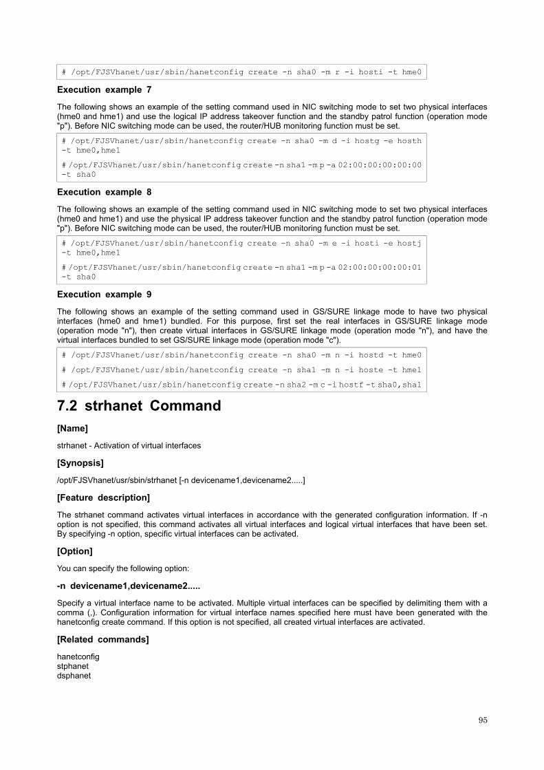
# /opt/FJSVhanet/usr/sbin/hanetconfig create -n sha0 -m r -i hosti -t hme0
Execution example 7
The following shows an example of the setting command used in NIC switching mode to set two physical interfaces (hme0 and hme1) and use the logical IP address takeover function and the standby patrol function (operation mode "p"). Before NIC switching mode can be used, the router/HUB monitoring function must be set.
# /opt/FJSVhanet/usr/sbin/hanetconfig create -n sha0 -m d -i hostg -e hosth -t hme0,hme1
# /opt/FJSVhanet/usr/sbin/hanetconfig create -n sha1 -m p -a 02:00:00:00:00:00 -t sha0
Execution example 8
The following shows an example of the setting command used in NIC switching mode to set two physical interfaces (hme0 and hme1) and use the physical IP address takeover function and the standby patrol function (operation mode "p"). Before NIC switching mode can be used, the router/HUB monitoring function must be set.
# /opt/FJSVhanet/usr/sbin/hanetconfig create -n sha0 -m e -i hosti -e hostj -t hme0,hme1
# /opt/FJSVhanet/usr/sbin/hanetconfig create -n sha1 -m p -a 02:00:00:00:00:01 -t sha0
Execution example 9
The following shows an example of the setting command used in GS/SURE linkage mode to have two physical interfaces (hme0 and hme1) bundled. For this purpose, first set the real interfaces in GS/SURE linkage mode (operation mode "n"), then create virtual interfaces in GS/SURE linkage mode (operation mode "n"), and have the virtual interfaces bundled to set GS/SURE linkage mode (operation mode "c").
# /opt/FJSVhanet/usr/sbin/hanetconfig create -n sha0 -m n -i hostd -t hme0
# /opt/FJSVhanet/usr/sbin/hanetconfig create -n sha1 -m n -i hoste -t hme1
# /opt/FJSVhanet/usr/sbin/hanetconfig create -n sha2 -m c -i hostf -t sha0,sha1
7.2 strhanet Command
[Name]
strhanet - Activation of virtual interfaces
[Synopsis]
/opt/FJSVhanet/usr/sbin/strhanet [-n devicename1,devicename2.....]
[Feature description]
The strhanet command activates virtual interfaces in accordance with the generated configuration information. If -n option is not specified, this command activates all virtual interfaces and logical virtual interfaces that have been set. By specifying -n option, specific virtual interfaces can be activated.
[Option]
You can specify the following option:
-n devicename1,devicename2.....
Specify a virtual interface name to be activated. Multiple virtual interfaces can be specified by delimiting them with a comma (,). Configuration information for virtual interface names specified here must have been generated with the hanetconfig create command. If this option is not specified, all created virtual interfaces are activated.
[Related commands]
hanetconfig stphanet dsphanet
95

[Notes]
If an additional virtual interface is activated in Fast switching mode, nodes that have been activated in Fast switching mode may be temporarily overloaded.
This command can activate a virtual interface only if configuration information has already been set by using the hanetconfig command before executing this command. For details, see Chapter 3, "Installation".
Virtual interfaces used in a cluster system cannot be activated with this command.
No logical virtual interface can be specified for the -n option. Logical virtual interfaces are automatically activated when corresponding virtual interfaces are activated.
This command can be specified for virtual interfaces in Fast switching mode (operation mode "t"), RIP mode (operation mode "r"), Fast switching/RIP mode (operation mode "b"), and GS/SURE linkage mode (operation mode "c"). This command cannot be specified for virtual interfaces in NIC switching mode (operation mode "d" or "e"), standby patrol function (operation mode "p" or "q"), and GS/SURE linkage mode (operation mode "n"). NIC switching mode (operation mode "d" or "e") and the standby patrol function (operation mode "p" or "q") are automatically activated at system startup.
Virtual interfaces in GS/SURE linkage mode (operation mode "n") are automatically activated when a virtual interface that bundles these virtual interfaces is activated.
[Examples]
The following is an example in which all virtual interfaces defined in the configuration information for SynfinityLink (Redundant Line Control Function) are activated.
# /opt/FJSVhanet/usr/sbin/strhanet
The following is an example in which only the virtual interface sha2 defined in the configuration information for SynfinityLink (Redundant Line Control Function) is activated.
# /opt/FJSVhanet/usr/sbin/strhanet -n sha2
7.3 stphanet Command
[Name]
stphanet - Inactivation of virtual interfaces
[Synopsis]
/opt/FJSVhanet/usr/sbin/stphanet [-n devicename1,devicename2.....]
[Feature description]
The stphanet command inactivates virtual interfaces. If the -n option is not specified, this command inactivates all active virtual interfaces. By specifying the -n option, specific virtual interfaces can be inactivated.
[Option]
You can specify the following option:
-n devicename1,devicename2.....
Specify a virtual interface name to be inactivated. Multiple virtual interfaces can be specified by delimiting them with a comma (,). Virtual interface names specified here must have been activated by using the strhanet command. If this option is not specified, all active virtual interfaces are inactivated.
[Related commands]
strhanet dsphanet
[Notes]
Virtual interfaces used in a cluster system cannot be inactivated with this command.
Only logical virtual interfaces cannot be inactivated. By terminating virtual interfaces, related logical virtual interfaces are automatically terminated.
When inactivating virtual interfaces and logical virtual interfaces, a high-level application must be terminated first.
96

This command can be specified for virtual interfaces in Fast switching mode (operation mode "t"), RIP mode (operation mode "r"), Fast switching/RIP mode (operation mode "b"), and GS/SURE linkage mode (operation mode "c"). This command cannot be specified for virtual interfaces in NIC switching mode (operation mode "d" or "e"), standby patrol function (operation mode "p" or "q"), and GS/SURE linkage mode (operation mode "n"). NIC switching mode (operation mode "d") and the standby patrol function (operation mode "p") are automatically inactivated at system shutdown.
Virtual interfaces in GS/SURE linkage mode (operation mode "n") are automatically inactivated when a virtual interface that bundles these virtual interfaces in GS/SURE linkage mode (operation mode "c") is inactivated.
[Examples]
The following is an example in which all virtual interfaces (excluding virtual interfaces in cluster operation) defined in the configuration information for SynfinityLink (Redundant Line Control Function) are inactivated.
# /opt/FJSVhanet/usr/sbin/stphanet
The following is an example in which only the virtual interface sha2 defined in the configuration information for SynfinityLink (Redundant Line Control Function) is inactivated.
# /opt/FJSVhanet/usr/sbin/stphanet -n sha2
7.4 dsphanet Command
[Name]
dsphanet - Displaying the operation status of virtual interfaces
[Synopsis]
/opt/FJSVhanet/usr/sbin/dsphanet [-n devicename1,devicename2.....] | [-o] | [-c]
[Feature description]
The dsphanet command displays the current operation status of virtual interfaces and logical virtual interfaces. If the -n option is not specified, this command displays the statuses of all virtual interfaces that are properly defined. Specify the -n option to display the statuses of only specific virtual interfaces.
[Option]
You can specify the following options:
-n devicename1,devicename2.....
Specify the name of a virtual interface whose status should be displayed. You can specify more than one virtual interface by listing them delimited with a comma (,). If this option is not specified, this command displays all the virtual interfaces that are properly defined.
-o
Displays all communication parties of virtual interfaces defined in Fast switching mode (operation mode "t"). This option does not display communication parties of virtual interfaces not yet activated using the strhanet command.
-c
Displays the number of assigned connections defined in GS/SURE linkage mode (operation mode "c"). The number of connections is displayed as "-" if the concerned virtual interface is not activated. The number of connections is displayed as "-" also if the communication party monitoring function is not set or no connection is yet established.
[Display format]
The following shows the display formats used when no option is specified and when the -n option is specified.
# /opt/FJSVhanet/usr/sbin/dsphanet
Name Status Mode Device
+----------+--------+----+-------------------------------------------------------+
sha0 Active t hme0(ON),hme1(ON)
sha1 Inactive r hme2(OFF),hme3(OFF)
97
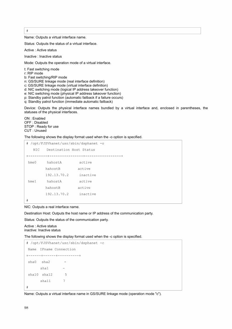
#
Name: Outputs a virtual interface name.
Status: Outputs the status of a virtual interface.
Active : Active status
Inactive : Inactive status
Mode: Outputs the operation mode of a virtual interface.
t: Fast switching mode r: RIP mode b: Fast switching/RIP mode n: GS/SURE linkage mode (real interface definition) c: GS/SURE linkage mode (virtual interface definition) d: NIC switching mode (logical IP address takeover function) e: NIC switching mode (physical IP address takeover function) p: Standby patrol function (automatic failback if a failure occurs) q: Standby patrol function (immediate automatic failback)
Device: Outputs the physical interface names bundled by a virtual interface and, enclosed in parentheses, the statuses of the physical interfaces.
ON : Enabled OFF : Disabled STOP : Ready for use CUT : Unused
The following shows the display format used when the -o option is specified.
# /opt/FJSVhanet/usr/sbin/dsphanet -o
NIC Destination Host Status
+---------+----------------+-----------------+
hme0 hahostA active
hahostB active
192.13.70.2 inactive
hme1 hahostA active
hahostB active
192.13.70.2 inactive
#
NIC: Outputs a real interface name.
Destination Host: Outputs the host name or IP address of the communication party.
Status: Outputs the status of the communication party.
Active : Active status inactive: Inactive status
The following shows the display format used when the -c option is specified.
# /opt/FJSVhanet/usr/sbin/dsphanet -c
Name IFname Connection
+------+------+----------+
sha0 sha2 -
sha1 -
sha10 sha12 5
sha11 7
#
Name: Outputs a virtual interface name in GS/SURE linkage mode (operation mode "c").
98

IFName: Outputs a virtual interface name in GS/SURE linkage mode (operation mode "n").
Connection: Outputs the number of connections.
[Related commands]
strhanet stphanet
[Notes]
This command can be specified for any virtual interfaces.
Only one option can be specified at one time.
[Examples]
The following shows an example of displaying the active or inactive status of all virtual interfaces that are properly defined in the configuration information for SynfinityLink (Redundant Line Control Function).
# /opt/FJSVhanet/usr/sbin/dsphanet
The following shows an example of displaying all the communication parties of virtual interfaces in Fast switching mode (operation mode "t") properly defined in the configuration information for SynfinityLink (Redundant Line Control Function).
# /opt/FJSVhanet/usr/sbin/dsphanet -o
The following shows an example of displaying the number of assigned connections of virtual interfaces in GS/SURE linkage mode (operation mode "c") properly defined in the configuration information for SynfinityLink (Redundant Line Control Function).
# /opt/FJSVhanet/usr/sbin/dsphanet -c
7.5 hanetobserv Command
[Name]
hanetobserv - Setting, modifying, deleting, and displaying the information for the communication party monitoring function
[Synopsis]
/opt/FJSVhanet/usr/sbin/hanetobserv command [args]
[Feature description]
The hanetobserv command sets, modifies, deletes, and displays the monitoring destination information required for the operation in GS/SURE linkage mode.
Command Process outline Authority
create Sets a monitoring destination Super user
print Displays monitoring destination information General user
modify Modifies monitoring destination information Super user
delete Deletes monitoring destination information Super user
(1) create command
The operation in GS/SURE linkage mode requires the monitoring of the communication party. This enables the system to continue communication using other communication paths when a failure occurs. Use the create command to generate a communication party. The following is the command format for generating a monitoring destination:
/opt/FJSVhanet/usr/sbin/hanetobserv create -n node -i ipaddr
-t nicaddr1[:pm-id][,nicaddr2[:pm-id],...] -m { on | off } |
-i ipaddr -c client1[:subnet][,client2[:subnet],...]
-n node:
Specify a name by which to identify the node of a communication party, using up to 16 one-byte characters.
99

-i ipaddress:
Specify a host name or IP address of a virtual interface held by the communication party. This host name must correspond to an IP address in a network database such as the /etc/inet/hosts file. You can directly specify an IP address instead of a host name. In this case, you must specify the IP address in dotted decimal notation.
-t nicaddr1[: pm-id][, nicaddr2[: pm-id],...]:
Specify the host names or IP addresses of real interfaces bundled by a virtual interface, by listing them delimited with a comma (,).
nicaddrX:
Specify the host name or IP address of a real interface bundled by a virtual interface.
pm-id:
Specify the identifier of the PM (processor module) group to which the real interface of the communication party belongs when it is the SURE system. Specify a number from 1 to 8. This option is not required if the communication party is GS.
-m on | off:
Set whether or not to monitor the virtual interface of the monitoring destination that has been set.
Since the local host need not monitor the communication party if the remote host monitors it, specify a mode depending on the setting of the remote host.
In hot standby configuration (GS), specify this parameter only on one of the active and standby nodes when their monitoring destination information is defined.
on:
The local host monitors the communication party.
off:
The local host does not monitor the communication party.
-c client1[: subnet][, client2[: subnet], ...]:
Specify the communication parties and destination networks with which communication should be performed using the virtual interface of the relay destination, by listing them delimited with a comma (,).
clientX:
Specify the host name or IP address of a remote host or network with which communication should be actually performed. This host name must correspond to an IP address in a network database such as the /etc/inet/hosts file. You can directly specify an IP address instead of a host name. In this case, you must specify the IP address in dotted decimal notation. If a remote network is specified, a "subnet" must be specified.
subnet:
This option must be specified when a remote network is specified in "clientX". Specify the subnet mask value of the network in dotted decimal notation.
(2) print command
Use the print command to display the current monitoring destination information. The following is the format of the print command. If no option is specified, information on both the monitoring destination and the relay destination is output.
/opt/FJSVhanet/usr/sbin/hanetobserv print [ { -o | -c } ]
-o:
Specify this option to output information on only the monitoring destination.
-c:
Specify this option to output information on only the relay destination.
The following shows an example of displaying monitoring destination information:
100

# /opt/FJSVhanet/usr/sbin/hanetobserv print
Destination Host Virtual Address POLL NIC Address(:PMgroupID)
+----------------+----------------+----+--------------------------------------+
hahostA ipaddressB ON interfaceC,interfaceD
interfaceE,interfaceF
hostB ipaddressG ON interfaceH:1,interfaceJ:1
Virtual Address Client Address
+----------------+------+-----------------------------------------------------+
ipaddressG host interfaceK
net 10.0.0.0:255.0.0.0
#
* The first real interface names in the real interface name list are interfaceC, interfaceE, and interfaceH in the above example.
Destination Host: Outputs the host name of the communication party.
Virtual Address: Outputs the virtual interface name.
POLL : Outputs the monitoring mode.
ON : The local host monitors the communication party. OFF: The local host does not monitor the communication party.
NIC Address(:PMgroupID): Outputs the real interface names bundled by a virtual interface. An ID value is shown in parentheses.
Virtual Address: Outputs the virtual interface name.
Client: Outputs the network type of the communication destination.
host: Indicates that the host address of the communication destination is output in "Address".
net: Indicates that the network address of the communication destination is output in "Address".
Address: Outputs address information of the communication destination.
(3) modify command
Use the modify command to modify the monitoring destination information generated using the create command. The following is the format of the modify command:
/opt/FJSVhanet/usr/sbin/hanetobserv modify -n node,new-node |
-n node -i ipaddress,new-ipaddress |
-n node -i ipaddress
{ -t interface,new-interface1[:pm-id][,new-interface2[:pm-id],...] |
-m { on | off } } |
-i ipaddress
-c clientaddress[:subnetmask],new-clientaddress[:subnetmask]
-n node[, new-node]:
Specify the node name of the monitoring destination information to be modified.
node:
Specify a node name that is set in the monitoring destination information (to be modified).
new-node:
Specify a node name to be used after modification.
If this parameter is specified, none of parameters "-i", "-t", and "-m" needs to be specified.
101

-i ipaddress[, new-ipaddress]:
Specify a host name or IP address of a virtual interface of the monitoring destination information to be modified. This parameter cannot be specified at the same time as when the node name or operation mode is modified.
ipaddress:
Specify a host name or IP address that is set in the monitoring destination information (to be modified).
new-ipaddress:
Specify a host name or IP address to be used after modification.
If this parameter is specified, none of new-node in parameter "-n" and parameters "-t" and "-m" needs to be specified.
-t interface, new-interface1[: pm-id][, new-interface2[: pm-id], ...]:
Specify the names of real interfaces bundled by a virtual interface of the monitoring information to be modified. This parameter cannot be specified at the same time as when the node name, host name or IP address of the virtual interface, or operation mode is modified.
interface:
Specify the first real interface names in the real interface name list that bundles real interface names that are set in the monitoring destination information (to be modified). Check the first real interface names using the print command of hanetobserv.
new-interface1[: pm-id][, new-interface2[: pm-id], ...]:
Specify all the real interface names to be bundled after modification, by listing them delimited with a comma (,).
If this parameter is specified, none of new-node in parameter "-n", new-ipaddress in parameter "-i", and parameter "-m" needs to be specified.
new-interfaceX:
Specify the host name or IP address of interfaces to be bundled by a virtual interface.
pm-id:
Specify the identifier of the PM (processor module) group to which the real interface of the communication party belongs when it is the SURE system. Specify a number from 1 to 8. This option is not required if the communication party is GS.
-m on | off:
Specify the operation mode of the monitoring destination information to be modified. This parameter cannot be specified at the same time as when the node name, host name or IP address of the virtual interface, or real interfaces bundled by a virtual interface is modified.
-c clientaddress[: subnetmask], new-clientaddress[: subnetmask]:
Modify the host name or IP address of the party with which communication should be actually performed. If a subnet mask value is specified in the information to be modified, the subnet mask value must be specified for modification.
clientaddress[: subnetmask]:
Specify the client information to be modified. If a subnet mask value is specified in the information that has been defined, the subnet mask value must be specified.
new-clientaddress[: subnetmask]:
Specify the client information to be used after modification. To specify a network, the subnet mask value must be specified.
(4) delete command
The following is the format of the delete command used to delete the monitoring destination information created using the create command:
/opt/FJSVhanet/usr/sbin/hanetobserv delete -n all |
-n node1[,node2,...] |
102
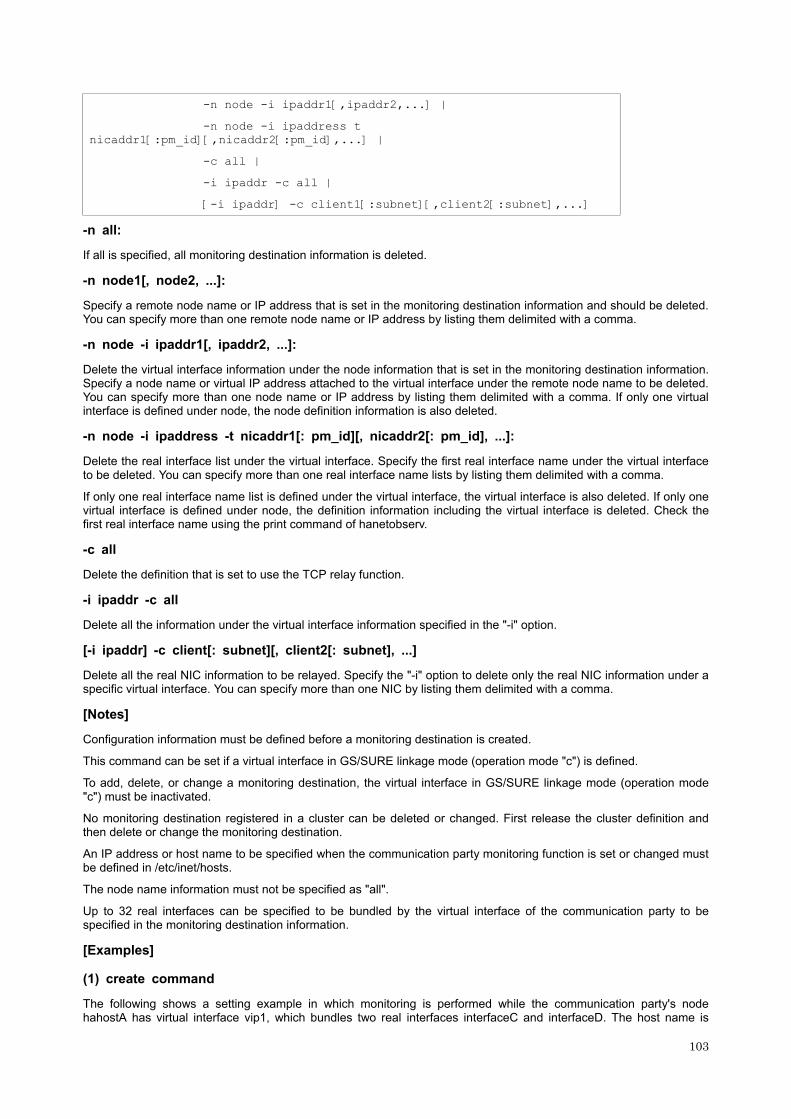
-n node -i ipaddr1[,ipaddr2,...] |
-n node -i ipaddress t nicaddr1[:pm_id][,nicaddr2[:pm_id],...] |
-c all |
-i ipaddr -c all |
[-i ipaddr] -c client1[:subnet][,client2[:subnet],...]
-n all:
If all is specified, all monitoring destination information is deleted.
-n node1[, node2, ...]:
Specify a remote node name or IP address that is set in the monitoring destination information and should be deleted. You can specify more than one remote node name or IP address by listing them delimited with a comma.
-n node -i ipaddr1[, ipaddr2, ...]:
Delete the virtual interface information under the node information that is set in the monitoring destination information. Specify a node name or virtual IP address attached to the virtual interface under the remote node name to be deleted. You can specify more than one node name or IP address by listing them delimited with a comma. If only one virtual interface is defined under node, the node definition information is also deleted.
-n node -i ipaddress -t nicaddr1[: pm_id][, nicaddr2[: pm_id], ...]:
Delete the real interface list under the virtual interface. Specify the first real interface name under the virtual interface to be deleted. You can specify more than one real interface name lists by listing them delimited with a comma.
If only one real interface name list is defined under the virtual interface, the virtual interface is also deleted. If only one virtual interface is defined under node, the definition information including the virtual interface is deleted. Check the first real interface name using the print command of hanetobserv.
-c all
Delete the definition that is set to use the TCP relay function.
-i ipaddr -c all
Delete all the information under the virtual interface information specified in the "-i" option.
[-i ipaddr] -c client[: subnet][, client2[: subnet], ...]
Delete all the real NIC information to be relayed. Specify the "-i" option to delete only the real NIC information under a specific virtual interface. You can specify more than one NIC by listing them delimited with a comma.
[Notes]
Configuration information must be defined before a monitoring destination is created.
This command can be set if a virtual interface in GS/SURE linkage mode (operation mode "c") is defined.
To add, delete, or change a monitoring destination, the virtual interface in GS/SURE linkage mode (operation mode "c") must be inactivated.
No monitoring destination registered in a cluster can be deleted or changed. First release the cluster definition and then delete or change the monitoring destination.
An IP address or host name to be specified when the communication party monitoring function is set or changed must be defined in /etc/inet/hosts.
The node name information must not be specified as "all".
Up to 32 real interfaces can be specified to be bundled by the virtual interface of the communication party to be specified in the monitoring destination information.
[Examples]
(1) create command
The following shows a setting example in which monitoring is performed while the communication party's node hahostA has virtual interface vip1, which bundles two real interfaces interfaceC and interfaceD. The host name is
103
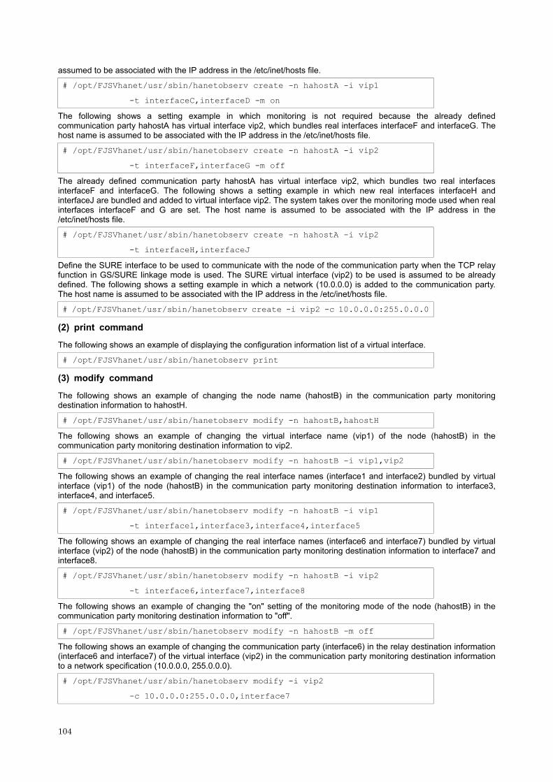
assumed to be associated with the IP address in the /etc/inet/hosts file.
# /opt/FJSVhanet/usr/sbin/hanetobserv create -n hahostA -i vip1
-t interfaceC,interfaceD -m on
The following shows a setting example in which monitoring is not required because the already defined communication party hahostA has virtual interface vip2, which bundles real interfaces interfaceF and interfaceG. The host name is assumed to be associated with the IP address in the /etc/inet/hosts file.
# /opt/FJSVhanet/usr/sbin/hanetobserv create -n hahostA -i vip2
-t interfaceF,interfaceG -m off
The already defined communication party hahostA has virtual interface vip2, which bundles two real interfaces interfaceF and interfaceG. The following shows a setting example in which new real interfaces interfaceH and interfaceJ are bundled and added to virtual interface vip2. The system takes over the monitoring mode used when real interfaces interfaceF and G are set. The host name is assumed to be associated with the IP address in the /etc/inet/hosts file.
# /opt/FJSVhanet/usr/sbin/hanetobserv create -n hahostA -i vip2
-t interfaceH,interfaceJ
Define the SURE interface to be used to communicate with the node of the communication party when the TCP relay function in GS/SURE linkage mode is used. The SURE virtual interface (vip2) to be used is assumed to be already defined. The following shows a setting example in which a network (10.0.0.0) is added to the communication party. The host name is assumed to be associated with the IP address in the /etc/inet/hosts file.
# /opt/FJSVhanet/usr/sbin/hanetobserv create -i vip2 -c 10.0.0.0:255.0.0.0
(2) print command
The following shows an example of displaying the configuration information list of a virtual interface.
# /opt/FJSVhanet/usr/sbin/hanetobserv print
(3) modify command
The following shows an example of changing the node name (hahostB) in the communication party monitoring destination information to hahostH.
# /opt/FJSVhanet/usr/sbin/hanetobserv modify -n hahostB,hahostH
The following shows an example of changing the virtual interface name (vip1) of the node (hahostB) in the communication party monitoring destination information to vip2.
# /opt/FJSVhanet/usr/sbin/hanetobserv modify -n hahostB -i vip1,vip2
The following shows an example of changing the real interface names (interface1 and interface2) bundled by virtual interface (vip1) of the node (hahostB) in the communication party monitoring destination information to interface3, interface4, and interface5.
# /opt/FJSVhanet/usr/sbin/hanetobserv modify -n hahostB -i vip1
-t interface1,interface3,interface4,interface5
The following shows an example of changing the real interface names (interface6 and interface7) bundled by virtual interface (vip2) of the node (hahostB) in the communication party monitoring destination information to interface7 and interface8.
# /opt/FJSVhanet/usr/sbin/hanetobserv modify -n hahostB -i vip2
-t interface6,interface7,interface8
The following shows an example of changing the "on" setting of the monitoring mode of the node (hahostB) in the communication party monitoring destination information to "off".
# /opt/FJSVhanet/usr/sbin/hanetobserv modify -n hahostB -m off
The following shows an example of changing the communication party (interface6) in the relay destination information (interface6 and interface7) of the virtual interface (vip2) in the communication party monitoring destination information to a network specification (10.0.0.0, 255.0.0.0).
# /opt/FJSVhanet/usr/sbin/hanetobserv modify -i vip2
-c 10.0.0.0:255.0.0.0,interface7
104

(4) delete command
The following shows an example of deleting all the monitoring destination information.
# /opt/FJSVhanet/usr/sbin/hanetobserv delete -n all
The following shows an example of deleting all the information held by the monitored host (hahostA).
# /opt/FJSVhanet/usr/sbin/hanetobserv delete -n hahostA
The following shows an example of deleting the information under the virtual interface (vip1) held by the monitored host (hahostA).
# /opt/FJSVhanet/usr/sbin/hanetobserv delete -n hahostA -i vip1
The following shows an example of deleting the information under the virtual interface (vip1) held by the monitored host (hahostA).
# /opt/FJSVhanet/usr/sbin/hanetobserv delete -n hahostA -i vip1
The following shows an example of deleting the real interface name list (interfaceC, interfaceD) under the virtual interface (vip1) in the TCP relay information.
# /opt/FJSVhanet/usr/sbin/hanetobserv delete -i vip1 -c interfacecC,interfacecD
7.6 hanetparam Command
[Name]
hanetparam - Setting up the monitoring function when Fast switching mode, NIC switching mode, or the standby patrol function is used
[Synopsis]
/opt/FJSVhanet/usr/sbin/hanetparam print | {-w | -m | -l | -p | -o | -t | -d } value
[Feature description]
The hanetparam command sets up the monitoring function when the Fast switching operation or the standby patrol function is used. This command also changes the method of activating and inactivating Fast switching mode and NIC switching mode.
[Option]
You can specify the following options:
-w value
Specify the interval (value) for monitoring the communication party in Fast switching mode. A value from 0 to 300 can be specified. No monitoring is performed if 0 is specified in value. By default, 5 is specified. This parameter is enabled only for Fast switching mode.
-m value
Specify the monitoring retry count (value) before message output when the message output function for a line failure is enabled.
Specify the monitoring retry count (value) before message output. A value from 0 to 100 can be specified. No message is output if 0 is specified in value. By default, no message is output. This parameter is enabled only for Fast switching mode.
-l value
Specify the inter-cluster failover (inter-node job switching) function.
Specify how many times (count) communication with the communication party can fail consecutively before inter-cluster failover (inter-node job switching) is performed. A value from 0 to 100 can be specified. No inter-cluster failover (inter-node job switching) is performed if 0 is specified in value. By default, inter-cluster failover (inter-node job switching) is specified to be performed if communication fails five consecutive times. This parameter is enabled only for Fast switching mode.
105

-p value
Specify the interval (value) for monitoring the communication party when the standby patrol function is enabled. A value from 0 to 100 can be specified. No monitoring is performed if 0 is specified in value. By default, 15 is specified. This parameter is enabled only for NIC switching mode.
-o value
Specify the monitoring retry count (value) before message output when the message output function for a standby patrol failure is enabled.
Specify the monitoring retry count (value) before message output. A value from 0 to 100 can be specified. No message is output if 0 is specified in value. By default, 3 is specified. This parameter is enabled only for NIC switching mode.
-t value
Use this parameter to change the activation timing of a virtual interface in Fast switching mode registered in the cluster resources. Specify "initialize" or "init" in value to activate the relevant virtual interface when the system is started up. This procedure allows "INTERSTAGE Traffic Director", etc. to be used as the host application. Alternatively, specify "cluster" in value to activate the relevant virtual interface according to an instruction from the cluster management daemon when the system is started up. Initially, "cluster" is specified in value. This parameter is enabled only for Fast switching mode.
-d value
Use this parameter to change the method of inactivating the standby interface in NIC switching mode. Specify "plumb" in value to inactivate the standby interface and set "0.0.0.0" as the IP address. This procedure allows "INTERSTAGE Traffic Director", etc. to be used as the host application. Alternatively, specify "unplumb" in value to inactivate and delete the standby interface. Initially, "unplumb" is specified in value. This parameter is enabled only for NIC switching mode.
print:
Outputs a list of settings.
The following shows the output format:
# /opt/FJSVhanet/usr/sbin/hanetparam print
Line monitor interval(w) :5
Line monitor message output(m) :0
Cluster failover(l) :5
Standby patrol interval(p) :15
Standby patrol message output(o) :3
Fast switching mode(t) :Cluster
NIC switching mode(d) :Plumb
Line monitor interval (w): Outputs the setting for the transmission line monitoring interval. Line monitor message output (m): Outputs the monitoring retry count before message output when a line failure occurs. Cluster failover (l): Outputs the consecutive monitoring failure count before execution of inter-cluster failover. Standby patrol interval (p): Outputs the monitoring interval of the standby patrol. Standby patrol message output (o): Outputs the consecutive monitoring failure count before output of a message when a standby patrol failure occurs. Fast switching mode (t): Outputs the timing of activating Fast switching mode registered in the cluster resources.
Cluster: Activates the virtual interface according to an activation instruction from the cluster service.
Initialize: Activates the virtual interface when the system is initialized.
NIC switching mode (d): Outputs the method of inactivating the standby interface in NIC switching mode. Unplumb: Inactivates the standby interface and deletes. Plumb: Inactivates the standby interface and sets the IP address as "0.0.0.0".
[Related command]
hanetpoll
106

[Notes]
This command can be specified for a virtual interface in Fast switching mode (operation mode "t"), NIC switching mode (operation mode "d" or "e"), and standby patrol function (operation mode "p" or "q").
[Examples]
(1) Example of setting line failure monitoring interval (enabled in Fast switching mode)
The following shows an example of using this command to perform monitoring at intervals of 5 seconds.
# /opt/FJSVhanet/usr/sbin/hanetparam -w 5
(2) Example of enabling or disabling the message output function used when a line failure occurs (enabled in Fast switching mode)
The following shows an example of using this command to output a message if communication with the communication party fails five consecutive times.
# /opt/FJSVhanet/usr/sbin/hanetparam -m 5
(3) Example of setting the inter-cluster failover (inter-node job switching) function (enabled in Fast switching mode)
The following shows an example of using this command to perform inter-cluster failover (inter-node job switching) if communication with the communication party fails five consecutive times.
# /opt/FJSVhanet/usr/sbin/hanetparam -l 5
(4) Example of setting the standby patrol monitoring interval (enabled in NIC switching mode)
The following shows an example of using this command to perform monitoring at intervals of five seconds.
# /opt/FJSVhanet/usr/sbin/hanetparam -p 5
(5) Example of setting the message output function used when a standby patrol failure occurs (enabled in NIC switching mode)
The following shows an example of using this command to output a message when communication with the communication party fails five consecutive times.
# /opt/FJSVhanet/usr/sbin/hanetparam -o 5
(6) Example of setting the activation timing in Fast switching mode registered in the cluster resources (enabled in Fast switching mode)
The following shows an example of using this command to activate the virtual interface when the system is initialized (using "INTERSTAGE Traffic Director", etc. as the host application).
# /opt/FJSVhanet/usr/sbin/hanetparam -t initialize
(7) Example of changing the method of inactivating the standby interface (enabled in NIC switching mode)
The following shows an example of using this command to inactivate the standby interface and set "0.0.0.0" as the IP address (using "INTERSTAGE Traffic Director", etc. as the host application).
# /opt/FJSVhanet/usr/sbin/hanetparam -d plumb
(8) Example of executing the status display command
The following shows an example of displaying the settings made using the hanetparam command.
# /opt/FJSVhanet/usr/sbin/hanetparam print
7.7 hanetpoll Command
[Name]
hanetpoll - Setting, modifying, deleting, and displaying the monitoring destination information for the Router/HUB monitoring function
107

[Synopsis]
/opt/FJSVhanet/usr/sbin/hanetpoll command [args]
[Feature description]
The hanetpoll command sets the monitoring destination information required for the Router/HUB monitoring function. This command also modifies, deletes, displays, enables, or disables the settings.
command Process outline Authority
create Creates monitoring destination information Super user
copy Copies monitoring destination information Super user
print Displays monitoring destination information General user
modify Modifies monitoring destination information Super user
delete Deletes monitoring destination information Super user
on Enabling the Router/HUB monitoring function Super user
off Disabling the Router/HUB monitoring function Super user
(1) create command
The operation of the router/HUB monitoring function requires the definition of monitoring destination information. Use the create command to define monitoring destination information.
/opt/FJSVhanet/usr/sbin/hanetpoll create -n devicename -p polladdr1[,polladd2 [-b {on | off}]]
-n devicename:
Specify the name of a virtual interface to be monitored. Specify a virtual interface created using the hanetconfig create command or the hanetconfig copy command. No logical virtual interface name can be specified.
-p polladdr1[,polladdr2]:
Specify the host names or IP addresses to be monitored, in the order of monitoring (polladdr1 is monitored first).
In RIP mode, specify the host names or IP addresses of neighboring routers as the monitoring destinations.
In NIC switching mode, specify the host names or IP addresses of HUBs to be connected.
Either one or two monitoring destinations can be specified.
-b on | off:
If two HUBs are specified as monitoring destinations in NIC switching mode, communication between the primary and secondary HUBs can be monitored.
on: Monitors communication between two HUBs. off: Does not monitor communication between two HUBs.
(2) copy command
Use the copy command to create copy monitoring destination information on a virtual interface in NIC switching mode. This command thus allows monitoring destination information to be automatically created by using the copy source information and without requiring you to specify monitoring destination information and HUB-HUB monitoring mode. This command realizes simpler operation than directly executing the hanetpoll create command. The following is the command format for the copy command:
/opt/FJSVhanet/usr/sbin/hanetpoll copy -n devicename1,devicename2
-n devicename1,devicename2:
Specify the names of virtual interfaces from and to which monitoring destination information should be copied.
devicename1:
Specify the name of a virtual interface that is set in monitoring information in the copy source.
108

devicename2:
Specify the name of a new virtual interface to be monitored. Specify a virtual interface created using the hanetconfig create command or the hanetconfig copy command. No logical virtual interface name can be specified.
(3) print command
Use the print command to display the current monitoring destination information. Use this command to view the current monitoring destination information. The following is the format of the print command.
/opt/FJSVhanet/usr/sbin/hanetpoll print [-n devicename1,devicename2...]
devicename1,devicename2...:
Specify the names of virtual interfaces whose monitoring destination information should be displayed. If this option is not specified, the print command displays all the monitoring destination information currently specified.
The following shows an example of displaying information without any option specified.
# /opt/FJSVhanet/usr/sbin/hanetpoll print
Polling Status = OFF
interval(idle) = 5( 30) sec
time = 5 times
max_retry = 5 retry
repair_time = 5 sec
FAILOVER Status = YES
Name HUB Poll Hostname
+-------+--------+------------------------------------------------------+
sha0 OFF hostA,10.0.1.1
Polling Status: Displays the current status of the monitoring function.
ON: The monitoring function is enabled. OFF: The monitoring function is disabled.
interval (idle):
interval: Displays the monitoring interval in the stationary status.
idle: Displays in seconds the wait time that elapses after monitoring starts and before the HUB links up.
times: Displays the monitoring count.
max_retry: Displays the consecutive failure occurrence count before failure notification.
repair_time: Displays the recovery monitoring interval in seconds.
FAILOVER Status: Displays the mode of inter-node switching used when a failure occurs.
YES: Inter-node switching is performed when the virtual interface is registered in the cluster resource. NO: No inter-node switching is performed.
Name: Displays the name of a virtual interface to be monitored.
HUB Poll: Displays the inter-HUB monitoring status.
ON: The monitoring function is enabled. OFF: The monitoring function is disabled. ---: The monitoring function is not used.
Hostname: Displays the host name or IP address to be monitored, in the order of the primary and secondary monitoring destinations. In the example, "hostA" is the primary monitoring destination and "10.0.1.1" is the secondary monitoring destination.
(4) modify command
Use the modify command to modify the monitoring destination information.
/opt/FJSVhanet/usr/sbin/hanetpoll modify -n devicename {-p polladdr1[,polladd2]} | {-b {on | off}}
109

-n devicename:
Specify the name of a virtual interface whose monitoring destination information should be modified. Specify a virtual interface whose monitoring destination information is currently defined.
-p polladdr1[,polladdr2]:
Specify the host names or IP addresses of the monitoring destinations to be modified. In RIP mode, specify the host names or IP addresses of neighboring routers as the monitoring destinations. In NIC switching mode, specify the host names or IP addresses of the primary and secondary HUBs.
-b on | off:
If two HUBs are specified as monitoring destinations in NIC switching mode, communication between the primary and secondary HUBs can be monitored. This parameter cannot be specified for the monitoring destination information in RIP mode.
on: Monitors communication between two HUBs. off: Does not monitor communication between two HUBs.
(5) delete command
Use the delete command to delete the monitoring destination information. The following is the format of the delete command:
/opt/FJSVhanet/usr/sbin/hanetpoll delete -n devicename1,devicename2... | all
-n devicename1,devicename2...:
Specify the names of virtual interfaces (such as sha0 and sha1) whose monitoring destination information should be deleted.
all:
Specify this parameter to delete all the defined monitoring destination information.
(6) on command
Use the on command to enable the generated router/HUB monitoring function. The following is the format of the on command:
/opt/FJSVhanet/usr/sbin/hanetpoll on [-s sec] [-c time] [-r retry] [-b sec] [-f yes | no] [-p sec]
-s sec:
Specify the monitoring time in seconds. A value from 1 to 300 can be specified (note that the product of sec and time must be 300 or less). If this option is not specified, the previous setting is enabled. Initially, 5 (seconds) is specified.
-c time:
Specify the monitoring count. A value from 1 to 300 can be specified (note that the product of sec and time must be 300 or less). If this option is not specified, the previous setting is enabled. Initially, 5 (times) is specified.
-r retry:
Specify the retry count at which the router monitoring should be stopped when a failure is detected. A value from 0 to 99999 can be specified. If this option is not specified, the previous setting is enabled. Initially, 5 (times) is specified. Specify 0 if the router monitoring should not be stopped.
This parameter need not be specified for a virtual interface in NIC switching mode (operation mode "d") because "1" (fixed) is set for it.
-b sec:
Specify the recovery monitoring interval used when a failure is detected. A value from 0 to 300 can be specified. If this option is not specified, the previous setting is enabled. Initially, 5 (seconds) is specified.
-f yes | no:
Specify the operation used when inter-node switching occurs due to a line failure during cluster operation. If this option is not specified, the previous setting is enabled. Initially, "yes" is specified. (This parameter is enabled only during cluster operation.)
110

yes: Inter-node switching is performed if a line monitoring failure occurs. no: No inter-node switching is performed if a line monitoring failure occurs.
-p sec:
Specify in seconds the wait time that should elapse after monitoring starts and before the HUB links up in NIC switching mode. A value from 1 to 300 can be specified. If this option is not specified, the previous setting is enabled. Initially, 60 (seconds) is specified. If the specified value is less than the monitoring interval multiplied by the monitoring count, the system ignores the specified link-up time and adopts the time obtained by multiplying the monitoring interval by the monitoring count.
(7) off command
Use the off command to disable the router/HUB monitoring function. The following is the format of the off command:
/opt/FJSVhanet/usr/sbin/hanetpoll off
[Notes]
Be sure to specify address information for neighboring routers (routers in the subnet to which physical interfaces bundled by the specified virtual interface belong) as the router monitoring destination. If any other address information is specified, the router/HUB monitoring function may not operate properly.
Before monitoring destination information can be specified using this command, configuration information must be set using the hanetconfig command.
This command can be specified for a virtual interface in RIP mode (operation mode "r"), Fast switching/RIP mode (operation mode "b"), and NIC switching mode (operation mode "d" or "e"). (In GS/SURE linkage mode, only the functions of enabling and disabling the monitoring function are available.)
After modifying monitoring destination information, disable the router/HUB monitoring function (hanetpoll off) and then enable it again (hanetpoll on). If the router/HUB monitoring function is enabled while it has already been enabled (duplicated activation of hanetpoll on), no monitoring destination information is reflected after modification.
A virtual interface to be used in the cluster system is monitored only while a service to which the virtual interface belongs is in operation.
If a virtual interface to be monitored is set to Fast switching mode, an error message is output to indicate this fact and the line is not monitored.
The monitoring time and count to be specified using the hanetpoll on command must be specified so that their product does not exceed 300.
The retry count to be specified using the hanetpoll on command can be set to 0 from 99999. Monitoring continues indefinitely if 0 is specified.
Use the hanetpoll print command to display the latest user-defined information (result of create, delete, modify, on, and off) but not to display the current status of router monitoring.
If any valid monitoring destination information exists, monitoring automatically starts when the system is started up.
Be sure to define in the /etc/inet/hosts file IP addresses and host names to be specified when the monitoring destination information is set or modified.
[Examples]
(1) create command
The following shows an example of creating configuration information for monitoring two routers routerA and routerB on virtual interface sha2. The host name is assumed to be associated with the IP address in the /etc/inet/hosts file.
# /opt/FJSVhanet/usr/sbin/hanetpoll create -n sha2 -p routerA,routerB
(2) copy command
The following shows an example of copying monitoring destination information on virtual interface sha0 to sha1 in NIC switching mode. In the monitoring destination information, PHUB and SHUB are already defined as the primary and secondary monitored HUBs.
# /opt/FJSVhanet/usr/sbin/hanetpoll copy -n sha0,sha1
(3) print command
The following shows an example of displaying the configuration information list of a virtual interface.
111

# /opt/FJSVhanet/usr/sbin/hanetpoll print
(4) modify command
The following shows an example of changing configuration information for monitoring two routers routerA and routerB to routerA and routerC on virtual interface sha2. The host name is assumed to be associated with the virtual IP address in the /etc/inet/hosts file.
# /opt/FJSVhanet/usr/sbin/hanetpoll modify -n sha2 -p routerA,routerC
(5) delete command
The following shows an example of deleting the monitoring destination information on virtual interface sha2 from the definition.
# /opt/FJSVhanet/usr/sbin/hanetpoll delete -n sha2
(6) on command
The following shows an example of starting the router/HUB monitoring function.
# /opt/FJSVhanet/usr/sbin/hanetpoll on
(7) off command
The following shows an example of stopping the router/HUB monitoring function.
# /opt/FJSVhanet/usr/sbin/hanetpoll off
7.8 dsppoll Command
[Name]
dsppoll - Displaying the monitoring status
[Synopsis]
/opt/FJSVhanet/usr/sbin/dsppoll [-c]
[Feature description]
The dsppoll command displays the current monitoring status of monitoring information created using the hanetpoll or hanetobserv command.
[Option]
You can specify the following options:
-c
Displays monitoring destination information in GS/SURE linkage mode (operation mode "c") created using the hanetobserv command.
[Display format]
The following shows the display format used when no option is specified.
# /opt/FJSVhanet/usr/sbin/dsppoll
Polling Status = ON
inter(idle) = 6( 60)
times = 12
retry = 5
repair_time = 5
FAILOVER Status = YES
Status Name Mode Primary Target/Secondary Target HUB-HUB
112

+------+------+----+-------------------------------------------+-------+
ON sha0 d 192.13.74.2(ON)/192.13.74.3(WAIT) ACTIVE
ON sha2 r 192.13.77.7(ON)/192.13.79.9(WAIT) ----
Polling Status: Displays the current status of the monitoring function.
ON: The monitoring function is enabled. OFF: The monitoring function is disabled.
interval (idle) :
interval : Displays in seconds the monitoring interval in the stationary status. Idle : Displays in seconds the wait time that elapses after monitoring starts and before the HUB links up.
times: Displays the monitoring count.
retry: Displays the retry count at which router monitoring should be stopped if a failure is detected.
This parameter is meaningless for a virtual interface in NIC switching mode (operation mode "d" or "e") because "1" is set for it.
repair_time : Displays the recovery monitoring interval in seconds.
FAILOVER Status : Displays the mode of inter-node switching used when a failure occurs.
YES : Inter-node switching is performed when the virtual interface is registered in the cluster resource. NO : No inter-node switching is performed.
Status: Displays the current status of the monitoring function.
ON : Monitoring is in progress. OFF : Monitoring is stopped.
Name: Displays the name of a virtual interface to be monitored.
Mode: Displays the operation mode of a virtual interface to be monitored.
r: RIP mode b: Fast switching/RIP mode d: NIC switching mode (logical IP address takeover function) e: NIC switching mode (physical IP address takeover function)
Primary Target/Secondary Target: Displays the primary and secondary monitoring destinations and the monitoring destination statuses.
ON: Monitoring is in progress. WAIT: Waiting is in progress. FAIL: Monitoring failed (monitoring is stopped).
HUB-HUB: Displays the status of HUB-HUB communication monitoring.
ACTIVE: Monitoring is in progress. FAIL: Monitoring failed. WAIT: Initial status OFF: Monitoring is not yet performed. ----: Monitoring destination not specified
The following is the display format of monitoring status obtained when the -c option is specified.
# /opt/FJSVhanet/usr/sbin/dsppoll -c
Polling Status = ON
inter = 5
times = 5
repair_time = 5
FAILOVER Status = YES
Node VIP Mode NIC Status
+----------------+----------------+----+----------------+------+
192.13.75.1 192.13.75.13 ON hahostA ACTIVE
113

192.13.73.12 FAIL
192.13.72.19 ACTIVE
192.13.73.19 ACTIVE
hahostB hahostC ON 192.13.72.19 ACTIVE
192.13.73.19 ACTIVE
hahostB OFF 192.13.72.19 ----
192.13.73.19 ----
Polling Status: Displays the current status of the monitoring function.
ON: The monitoring function is enabled. OFF: The monitoring function is disabled.
inter: Displays the monitoring interval.
times: Displays the monitoring count.
repair_time : Displays the recovery monitoring interval in seconds.
FAILOVER Status : Displays the mode of inter-node switching used when a failure occurs.
YES: Inter-node switching is performed when the virtual interface is registered in the cluster resource. NO: No inter-node switching is performed.
Node: Displays the name of a node to be monitored.
VIP: Displays the name of a virtual interface held by the monitored node.
Mode: Displays the operation mode of a virtual interface to be monitored.
ON: The monitoring function is enabled. OFF: The monitoring function is disabled.
NIC: Displays the hostname or IP address of a real interface to be monitored.
Status: Displays the monitoring status of a virtual interface.
ACTIVE: Monitoring is in progress. FAIL: Monitoring failed (recover monitoring in progress). ----: Monitoring is not yet performed.
[Related commands]
hanetpoll hanetobserv
[Notes]
If no option is specified, this command can be specified for a virtual interface in RIP mode (operation mode "r"), Fast switching/RIP mode (operation mode "b"), or NIC switching mode (operation mode "d" or "e").
If the "-c" option is specified, this command can be specified for a virtual interface in GS/SURE linkage mode (operation mode "c").
[Examples]
(1) The following shows an example of displaying all the monitoring statuses properly defined using the hanetpoll command.
# /opt/FJSVhanet/usr/sbin/dsppoll
(2) The following shows an example of displaying all the monitoring statuses properly defined using the hanetobserv command.
# /opt/FJSVhanet/usr/sbin/dsppoll -c
114

7.9 hanetnic Command
[Name]
hanetnic - Dynamic addition/deletion/switching of real interfaces
[Synopsis]
/opt/FJSVhanet/usr/sbin/hanetnic command [args]
[Feature description]
The hanetnic command can add, delete, or switch real interfaces to be used dynamically while the relevant virtual interface is active.
Command Process outline Authority
add Adds real interfaces Super user
delete Deletes real interfaces Super user
change Changes real interface used Super user
(1) add command
This command adds real interfaces bundled by a virtual interface in Fast switching mode dynamically. (Real interfaces are added while the virtual interface is active.) However, only real interfaces specified in configuration information can be specified. The following is the format of the add command:
/opt/FJSVhanet/usr/sbin/hanetnic add -n devicename -i interfacename
-n devicename:
Specify a virtual interface name to which the real interface to be added belongs. It is possible to specify only virtual interface names with Fast switching mode (operation mode "t") or Fast switching/RIP mode (operation mode "b") specified.
-i interfacename:
Specify the real interface name to be added. The interface name specified here must have been set in configuration information for the relevant virtual interface.
(2) delete command
This command deletes real interfaces bundled by a virtual interface in Fast switching mode dynamically (Real interfaces are deleted while the virtual interface is active). However, only real interfaces specified in configuration information can be specified. The following is the format of the delete command:
/opt/FJSVhanet/usr/sbin/hanetnic delete -n devicename -i interfacename
-n devicename:
Specify a virtual interface name to which the real interface to be deleted belongs. It is possible to specify only virtual interface names with Fast switching mode (operation mode "t") or Fast switching/RIP mode (operation mode "b").
-i interfacename:
Specify the real interface name to be deleted. The interface name specified here must have been set in the configuration information for the relevant virtual interface.
(3) change command
This command changes real interfaces used in a virtual interface in NIC switching mode to those of the standby system. The following is the format of the change command:
/opt/FJSVhanet/usr/sbin/hanetnic change -n devicename
-n devicename:
Specify the virtual interface name of the used real interface to be changed. It is possible to specify only virtual interface names with NIC switching mode (operation mode "d" or "e") specified.
115

[Notes]
This command can be specified for virtual interfaces in Fast switching mode (operation mode "t") or NIC switching mode (operation mode "d" or "e").
[Examples]
(1) add command
The following example adds hme0 to the bundled real interfaces in the virtual interface sha0. It is assumed that sha0 has already been defined in Fast switching mode (operation mode "t") and hme0 has been deleted by using the "hanetnic delete" command.
# /opt/FJSVhanet/usr/sbin/hanetnic add -n sha0 -i hme0
(2) delete command
The following example deletes hme1 from the bundled real interfaces in the virtual interface sha0. It is assumed that sha0 has already been defined in Fast switching mode (operation mode "t").
# /opt/FJSVhanet/usr/sbin/hanetnic delete -n sha0 -i hme1
(3) change command
The following example replaces real interfaces used in the virtual interface sha0 with those of the standby system. It is assumed that sha0 has already been defined in NIC switching mode (operation mode "d").
# /opt/FJSVhanet/usr/sbin/hanetnic change -n sha0
7.10 strptl Command
[Name]
strptl - Starting the standby patrol
[Synopsis]
/opt/FJSVhanet/usr/sbin/strptl -n devicename1[,devicename2....]
[Feature description]
The strptl command starts the standby patrol in NIC switching mode.
[Option]
You can specify the following option:
-n devicename1[, devicename2....]
Specify the name of a virtual interface of the standby patrol to be started. You can specify more than one virtual interface by listing them delimited with a comma (,).
[Related commands]
stpptl
[Notes]
The standby patrol is automatically started when the system is started up. Use this command to start the standby patrol manually after the system is started up.
[Examples]
The following shows an example of starting the standby patrol defined in a virtual interface (sha4).
# /opt/FJSVhanet/usr/sbin/strptl -n sha4
116

7.11 stpptl Command
[Name]
stpptl - Stopping the standby patrol
[Synopsis]
/opt/FJSVhanet/usr/sbin/stpptl -n devicename1[,devicename2....]
[Feature description]
The stpptl command stops the standby patrol in NIC switching mode.
[Option]
You can specify the following option:
-n devicename1[, devicename2....]
Specify the name of a virtual interface of the standby patrol to be stopped. You can specify more than one virtual interface by listing them delimited with a comma (,).
[Related commands]
strptl
[Notes]
The standby patrol is automatically stopped when the system is shut down. Use this command to stop the standby patrol manually after the system is started up.
[Examples]
The following shows an example of stopping the standby patrol defined in a virtual interface (sha4).
# /opt/FJSVhanet/usr/sbin/stpptl -n sha4
7.12 hanetbackup Command
[Name]
hanetbackup - Backing up the environment definition files
[Synopsis]
/opt/FJSVhanet/usr/sbin/hanetbackup [-d backupdir ]
[Feature description]
The hanetbackup command backs up the environment definition files used by SynfinityLink (Redundant Line Control Function). The backup files are named "hanetYYYYMMDD.bk". YYYYMMDD is the information obtained when the command is executed (YYYY, MM, and DD stands for the year, month and day, respectively).
[Option]
You can specify the following option:
-d backupdir
Specify a directory to which backup environment definition files should be saved. If this option is omitted, the backup files will be saved to under /tmp.
[Related commands]
hanetrestore
[Notes]
If the backup command is executed more than once on the same day using the same output destination, the backup file will be overwritten. Before executing this command, save as required the file that has been output using this
117

command.
[Examples]
The following shows an example of outputting environment definition files to under /tmp.
# /opt/FJSVhanet/usr/sbin/hanetbackup
7.13 hanetrestore Command
[Name]
hanetrestore - Restoring and converting the environment definition files
[Synopsis]
/opt/FJSVhanet/usr/sbin/hanetrestore -f backupfilename [-v version]
[Feature description]
The hanetrestore command restores the environment definition files used by SynfinityLink (Redundant Line Control Function). This command also converts the file format of the definition files so they can be used in this version.
[Option]
You can specify the following options:
-f backupfilename
Specify a file created using the backup command.
-v version
Specify the version of SynfinityLink (Redundant Line Control Function) that has executed the backup command.
If this option is omitted, version 2.2 is assumed.
[Related commands]
hanetbackup
[Notes]
A definition file saved using version 1.0 cannot be restored. Restore such a file according to the Installation Guide. After restoring a definition file, be sure to execute this command to convert the file format so the definition file can be used in this version.
To restore a definition file saved using version 1.1 and later, specify in the "-v" option of the hanetrestore command the version of SynfinityLink used to save the definition file.
After executing this command, be sure to reboot the system.
If a file saved using the backup command is restored, the file format is converted at the same time so the file can be used in this version.
[Examples]
The following shows an example of converting the format of an environment definition file created on SynfinityLink 1.0 so the file can be used on SynfinityLink 2.2.
# /opt/FJSVhanet/usr/sbin/hanetrestore -v 1.0
The following shows an example of restoring a file (/tmp/hanet19991231.bk) created using the backup command on SynfinityLink 1.1 to SynfinityLink 2.2.
# /opt/FJSVhanet/usr/sbin/hanetrestore -f /tmp/hanet19991231.bk -v 1.1
The following shows an example of restoring a file (/tmp/hanet19991231.bk) created using the backup command on SynfinityLink 2.0 to SynfinityLink 2.2.
# /opt/FJSVhanet/usr/sbin/hanetrestore -f /tmp/hanet19991231.bk -v 2.0
The following shows an example of restoring a file (/tmp/hanet19991231.bk) created using the backup command on SynfinityLink 2.2 to SynfinityLink 2.2.
118

# /opt/FJSVhanet/usr/sbin/hanetrestore -f /tmp/hanet19991231.bk [-v 2.2]
7.14 claddhanetrsc Command
[Name]
claddhanetrsc - Resource registration of virtual interfaces
[Synopsis]
/opt/FJSVhanet/sys/claddhanetrsc -n devicename
[Feature description]
The claddhanetrsc command registers the resource information for virtual interfaces specified with the -n option to the resource database managed by the cluster control facility.
[Option]
You can specify following option:
-n devicename
Specify the virtual interface name for the resource. This option is useful for the virtual interfaces that have already been created with the hanetconfig create command.
[Related commands]
hanetconfig
[Notes]
Before executing this command to register resources, the configuration information must have already been created with the hanetconfig command.
Necessary to give the same name to a virtual interface (shaX) to be specified by both nodes (active node and standby node).
This command must be executed for both nodes (active node and standby node).
Before executing this command, the cluster system must have already been installed. If this command is executed in a system that does not have the cluster system installed, this command outputs an error message and terminates abnormally.
Don't modify resource name by cluster management view. Setting procedure may not be conducted normally.
[Examples]
When registering the configuration information of the virtual interface shaX to the cluster resource.
# /opt/FJSVhanet/sys/claddhanetrsc -n sha0
7.15 claddhanetiprsc Command
[Name]
claddhanetiprsc - Registering the resource of a takeover IP address
[Synopsis]
/opt/FJSVhanet/sys/claddhanetiprsc -n devicename -i ip_address [-k key] [-d node ]
[Feature description]
The claddhanetiprsc command sets a takeover IP address on a virtual interface and registers the address resource (shared resource) used to perform the IP address takeover in the active standby configuration.
[Option]
You can specify the following options:
119

-n devicename:
Specify the name of a virtual interface whose resource should be registered. The resource of a virtual interface name to be specified must be registered using the claddhanetrsc command.
-i ip_address
Specify a takeover IP address.
In ip_address, specify an IP address or host name to be taken over. In NIC switching mode (operation mode "d" or "e"), no takeover IP address need to be specified for a virtual interface.
-k key
Specify the resource key of a shared resource to be registered. The resource key specified in this option is used as the resource name. This option may be omitted. If this option is omitted, the takeover IP address specified in the -i option is used as the resource key. As the resource key, you can specify only ASCII uppercase and lowercase alphabetic characters, numeric characters, hyphens ("-"), underlines ("_"), periods ("."), slashes ("/"), and colons (":"). The resource key must start with either an ASCII uppercase or lowercase alphabetic character or a numeric character.
-d node
Specify the name of a remote node that makes up a cluster. Specify this parameter for a N:1 configuration, i.e., if the same virtual interface name is specified for three or more nodes. This parameter may be omitted if the active standby configuration is 1:1.
[Notes]
The value specified in the "-k" option is used as the resource key of the takeover IP address. If the "-k" option is omitted, the takeover IP address is used as the resource key.
If a host name is specified in the "-i" option, the same IP address must be defined for the host name on both the nodes. If, on these nodes, different IP addresses are defined for the host name specified in the "-i" option , the takeover IP address will be the IP address obtained on the node on which this command has been executed.
Execute this command only on either of the nodes.
This command can be executed only if a cluster system is installed. If this command is executed in an environment where no cluster system is installed, the system outputs an error message and this command abnormally terminates.
The IP address or host name to be specified when a takeover IP address is specified must be defined in the /etc/inet/hosts file.
[Examples]
The following shows an example of specifying takeover IP address hostip in the configuration information of virtual interface sha0 and registering the resource with resource key name SLINK.
# /opt/FJSVhanet/sys/claddhanetiprsc -n sha0 -i hostip -k SLINK
The following shows an example of resource registration in the configuration information of virtual interface sha1 in NIC switching mode (The resource key name is omitted).
# /opt/FJSVhanet/sys/claddhanetiprsc -n sha1
7.16 claddhanetsvc Command
[Name]
claddhanetsvc - Setting a takeover IP address in the service
[Synopsis]
/opt/FJSVhanet/sys/claddhanetsvc -n devicename [-k key]
[Feature description]
The claddhanetsvc command registers a takeover IP address resource in the service tree.
[Option]
You can specify the following options:
120

-n devicename:
Specify the name of a virtual interface to be registered in the cluster service. A virtual interface to be specified must be registered in the resource of a takeover IP address using the claddhanetiprsc command.
-k key
Specify the name of a resource key specified in the takeover address or the "-k" option specified in the claddhanetiprsc command. This parameter must be specified for mutual standby operation in Fast switching mode. For other operations, this parameter may be omitted.
[Notes]
Execute this command only on either of the nodes.
Before executing this command, you must perform service registration using the Environment Setting menu of the cluster operation management view and set the takeover IP address resource specified in the takeover address setting.
This command can be executed only if a cluster system is installed. If this command is executed in an environment where no cluster system is installed, the system outputs an error message and this command abnormally terminates.
[Examples]
The following shows an example of registering configuration information of virtual interface sha0 to the service.
# /opt/FJSVhanet/sys/claddhanetsvc -n sha0
7.17 cldelhanetrsc Command
[Name]
cldelhanetrsc - Deleting the resource of a virtual interface
[Synopsis]
/opt/FJSVhanet/sys/cldelhanetrsc -n devicename
[Feature description]
The cldelhanetrsc command deletes the resource information of a virtual interface from the resource database held by the cluster control.
[Option]
You can specify the following option:
-n devicename:
Deletes the resource of a virtual interface registered in the cluster resource. Specify the name of a virtual interface to be deleted.
[Notes]
Check that no takeover IP address resource is set on the virtual interface to be deleted. If a takeover IP address is set on the virtual interface to be deleted, first execute the cldelhanetiprsc command to delete the takeover IP address set on the virtual interface.
This command must be executed on both the nodes.
This command can be executed only if a cluster system is installed. If this command is executed in an environment where no cluster system is installed, the system outputs an error message and this command abnormally terminates.
[Examples]
The following shows an example of deleting configuration information of virtual interface sha0 from the cluster resource.
# /opt/FJSVhanet/sys/cldelhanetrsc -n sha0
121
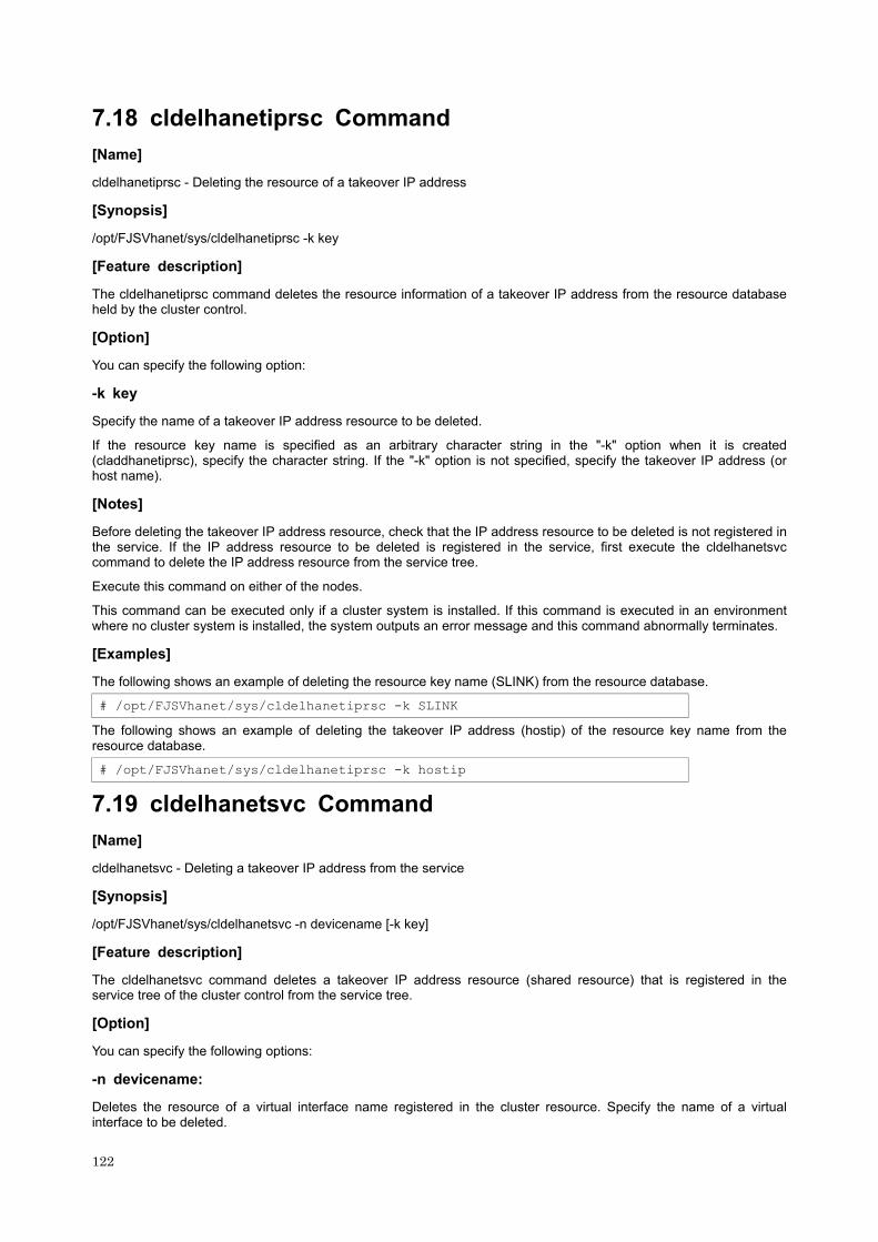
7.18 cldelhanetiprsc Command
[Name]
cldelhanetiprsc - Deleting the resource of a takeover IP address
[Synopsis]
/opt/FJSVhanet/sys/cldelhanetiprsc -k key
[Feature description]
The cldelhanetiprsc command deletes the resource information of a takeover IP address from the resource database held by the cluster control.
[Option]
You can specify the following option:
-k key
Specify the name of a takeover IP address resource to be deleted.
If the resource key name is specified as an arbitrary character string in the "-k" option when it is created (claddhanetiprsc), specify the character string. If the "-k" option is not specified, specify the takeover IP address (or host name).
[Notes]
Before deleting the takeover IP address resource, check that the IP address resource to be deleted is not registered in the service. If the IP address resource to be deleted is registered in the service, first execute the cldelhanetsvc command to delete the IP address resource from the service tree.
Execute this command on either of the nodes.
This command can be executed only if a cluster system is installed. If this command is executed in an environment where no cluster system is installed, the system outputs an error message and this command abnormally terminates.
[Examples]
The following shows an example of deleting the resource key name (SLINK) from the resource database.
# /opt/FJSVhanet/sys/cldelhanetiprsc -k SLINK
The following shows an example of deleting the takeover IP address (hostip) of the resource key name from the resource database.
# /opt/FJSVhanet/sys/cldelhanetiprsc -k hostip
7.19 cldelhanetsvc Command
[Name]
cldelhanetsvc - Deleting a takeover IP address from the service
[Synopsis]
/opt/FJSVhanet/sys/cldelhanetsvc -n devicename [-k key]
[Feature description]
The cldelhanetsvc command deletes a takeover IP address resource (shared resource) that is registered in the service tree of the cluster control from the service tree.
[Option]
You can specify the following options:
-n devicename:
Deletes the resource of a virtual interface name registered in the cluster resource. Specify the name of a virtual interface to be deleted.
122

-k key
Specify the resource key name of a takeover IP address resource to be deleted. This parameter must be specified for mutual standby operation in Fast switching mode. For other operations, this parameter may be omitted.
[Notes]
Before deleting the takeover IP address set in the service, you must temporarily stop the service.
Execute this command on either of the nodes.
This command can be executed only if a cluster system is installed. If this command is executed in an environment where no cluster system is installed, the system outputs an error message and this command abnormally terminates.
[Examples]
The following shows an example of deleting the configuration information of virtual interface sha0 from the service.
# /opt/FJSVhanet/sys/cldelhanetsvc -n sha0
123

124

Appendix A List of Error Messages
Appendix A explains the messages that SynfinityLink (Redundant Line Control Function) provides as output.
A.1 Messages Displayed by SynfinityLink (Redundant Line Control Function)
This section explains the meaning of, and action to take for each message output by SynfinityLink (Redundant Line Control Function) regarding such commands as the configuration commands and operation commands.
Each message has the following format:
[Output message]
1. A format for information messages and error output messages:
hanet: BBBCC DDDDD: EEEEE FFFFF (1) (3) (4) (5) (6)
2. A format for console output messages and internal information output messages:
hanet: AAAAA: BBBCC DDDDD: EEEEE FFFFF (1) (2) (3) (4) (5) (6)
(1) Component name
Always begins with "hanet".
(2) Error Kind
Console messages and internal information output messages output this, but not by other messages. The output information (AAAAA) is as follows:
ERROR:
Means that an output message is an error.
WARNING:
Means that an output message is a warning.
INFO:
Means that an output message is the information. This massage is output only when "3.3.8.3 Setting a history of the workings of an interface's up/down" is set.
TRACE:
This indicates internal information output messages.
(3) Message number (Displayed in total five digits.)
Outputs an output message with a unique number. Not displayed when output an internal message.
The first three digits (BBB) indicate the message number. The last two digits (CC) indicate the internal code.
(4) Outline of errors
The output information (DDDDD) is as follows. Not output when it is a console message.
information:
Means that an output message is the information.
warning:
Means that there is an error in the definition information (a process continues).
125
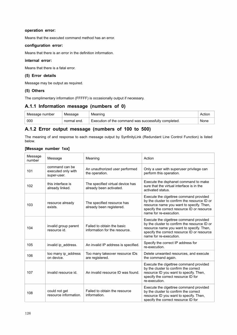
operation error:
Means that the executed command method has an error.
configuration error:
Means that there is an error in the definition information.
internal error:
Means that there is a fatal error.
(5) Error details
Message may be output as required.
(5) Others
The complimentary information (FFFFF) is occasionally output if necessary.
A.1.1 Information message (numbers of 0)
Message number Message Meaning Action
000 normal end. Execution of the command was successfully completed. None
A.1.2 Error output message (numbers of 100 to 500)
The meaning of and response to each message output by SynfinityLink (Redundant Line Control Function) is listed below.
[Message number 1xx]
Message number Message Meaning Action
101 command can be executed only with super-user.
An unauthorized user performed the operation.
Only a user with superuser privilege can perform this operation.
102 this interface is already linked.
The specified virtual device has already been activated.
Execute the dsphanet command to make sure that the virtual interface is in the activated status.
103 resource already exists.
The specified resource has already been registered.
Execute the clgettree command provided by the cluster to confirm the resource ID or resource name you want to specify. Then, specify the correct resource ID or resource name for re-execution.
104 invalid group parent resource id.
Failed to obtain the basic information for the resource.
Execute the clgettree command provided by the cluster to confirm the resource ID or resource name you want to specify. Then, specify the correct resource ID or resource name for re-execution.
105 invalid ip_address. An invalid IP address is specified. Specify the correct IP address for re-execution.
106 too many ip_address on device.
Too many takeover resource IDs are registered.
Delete unwanted resources, and execute the command again.
107 invalid resource id. An invalid resource ID was found.
Execute the clgettree command provided by the cluster to confirm the correct resource ID you want to specify. Then, specify the correct resource ID for re-execution.
108 could not get resource information.
Failed to obtain the resource information.
Execute the clgettree command provided by the cluster to confirm the correct resource ID you want to specify. Then, specify the correct resource ID for
126

re-execution.
109
specified resource could not operate, because service is not stopped.
Resource operation was rejected because the service is not stopped.
Execute the clgettree command provided by the cluster, or pull up the cluster operation management view and check the operation of the service that has the virtual interface you want to delete.
110 resource has been set to service tree still.
The specified source has been set on the resource service tree.
Delete the service, and execute the command again.
111 invalid parameter. An invalid parameter is specified. Read the appropriate command reference, and execute the command again.
112 invalid argument. An invalid command argument was found.
Read the appropriate command reference, and execute the command again.
113 polling already active.
The router monitoring function has already been activated. No action is required.
114 -r option value is invalid. An invalid value is specified.
Read the appropriate command reference to get the correct value, and execute the command again.
115 -s -c option total value is invalid. An invalid value is specified.
Specify the values (-s and -c) so that the product of the two values does not exceed 300, and execute the command again.
116 -s -c option value is invalid. An invalid value is specified.
The values (-s and -c) must be selected from within a range of 1 to 300. Specify a number within the range for each value, and execute the command again.
117 polling already stopped.
The router monitoring function has already been deactivated. No action is required.
118 interface is inactive. The specified virtual interface has been deactivated.
Execute the dsphanet command to check the status of the specified virtual interface.
119 interface is active. The specified virtual interface has been activated.
Execute the dsphanet command to check the status of the specified virtual interface.
120 invalid device name. An invalid virtual interface name is specified.
Specify the correct virtual interface name, and execute the command again.
121 directory not found. The specified directory was not found.
Specify a directory name that already exists, and execute the command again.
122 backup file not found. The specified backup file was not found.
Specify a backup file that already exists, and execute the command again.
123 invalid backup file. The specified backup file is invalid.
Specify the backup file that was created by the hanetbackup command, and execute the command again.
124 not directory Directory name was not found where directory was expected.
Specify a directory, and execute the command again.
125 interface is Cluster interface.
The specified interface is available in the cluster operation.
Specify an interface that is not being used in the cluster operation, and execute the command again.
126 shared resource is not found.
An invalid common resource is specified.
Specify a correct common resource name, and execute the command again.
127 invalid key An invalid resource key is specified.
Specify a correct resource key, and execute the command again.
128 invalid logicalIP. An invalid logical IP address is specified.
Specify a correct logical IP address, and execute the command again.
129 logicalIP is already defined.
The specified logical IP address has been specified in configuration information.
Specify a different logical IP address, and execute the command again.
127

130 logicalIP is not specified. No logical IP address is specified. Specify a logical IP address, and execute
the command again.
131 primaryIF is not specified. No primary interface is specified. Specify a primary interface, and execute
the command again.
132 invalid primaryIF. An invalid primary interface is specified.
Specify a correct primary interface, and execute the command again.
133 physicalIP is not specified.
No physical IP address is specified for the interface.
Specify a physical IP address for the interface, and execute the command again.
134 invalid physicalIP. The physical IP address of the interface is invalid.
Specify a correct physical IP address, and execute the command again.
135 primary polling address is not specified.
No monitoring destination IP address is specified for the primary interface.
Specify a monitoring destination IP address for the primary interface, and execute the command again.
136 invalid primary polling address.
The monitoring destination IP address of the primary interface is invalid.
Specify a correct monitoring destination IP address, and execute the command again.
137 secondaryIF is not specified.
No secondary interface is specified.
Specify a secondary interface, and execute the command again.
138 invalid secondaryIF. An invalid secondary interface is specified.
Specify a correct secondary interface, and execute the command again.
139 secondary polling address is not specified.
No monitoring destination IP address of the secondary interface is specified.
Specify a monitoring destination IP address of the secondary interface, and execute the command again.
140 invalid secondary polling address.
An invalid monitoring destination IP address is specified for the secondary interface.
Specify a correct monitoring destination IP address for the secondary interface, and execute the command again.
141 HUB-HUB polling flag is not specified.
Whether HUB-HUB communication monitoring is performed is not specified.
Specify whether to perform the HUB-HUB communication monitoring (ON or OFF), and execute the command again.
142 invalid HUB-HUB polling flag.
There is an error in the specification indicating whether HUB-HUB communication monitoring is performed.
Specify ON or OFF of the HUB-HUB communication monitoring, and execute the command again.
143 logicalIP is defined in physicalIP.
The IP address specified as a logical IP address overlaps the physical IP address.
Specify an IP address that is not specified in the virtual interface as the logical IP address, and execute the command again.
144 secondaryIF equal primaryIF.
The primary interface and the secondary interface are identical.
Specify different interfaces, and execute the command again.
145 interface is already defined in another set.
The specified interface is used in another operation set.
Specify an interface that is not used in other operation sets, and execute the command again.
146 interval is not specified.
No monitoring interval is specified.
Specify a monitoring interval, and execute the command again.
147 invalid interval specified.
The monitoring interval value is invalid.
Specify a correct monitoring interval, and execute the command again.
148 count is not specified. No monitoring count is specified. Specify a monitoring count, and execute
the command again.
149 invalid count specified.
The monitoring count value is invalid.
Specify a correct monitoring count, and execute the command again.
150 invalid argument. An invalid option is specified. Refer to the command reference, and execute the command again.
151 logocalIP is active. The specified processing could not be performed because the
Stop the transmission line monitoring, and execute the command again.
128

transmission line monitoring of the specified operation set was operating.
152 logocalIP is inactive.
The specified processing could not be performed because the transmission line monitoring of the specified operation set was stopped.
Start the transmission line monitoring, and execute the command again.
153 logicalIP is not defined.
The specified operation set is not defined. Specify a correct operation set.
154 logocalIP is registered to cluster resource.
The specified operation set is registered as a cluster resource.
Delete the operation set from the cluster resources.
155 invalid ping on/off.
HUB-HUB communication monitoring information specified in the operation set information is invalid.
Specify correct operation set information.
156 secondaryIF is not defined.
Because the secondary interface is not specified, interfaces cannot be switched.
Specify an operation set in which the secondary interface is defined.
157 product of interval and time should be less than 300.
The detection time (product of the monitoring interval and monitoring count) of line failure is too large.
Specify the monitoring interval and monitoring count so that their product does not exceed 300 seconds.
158 invalid interface count(max 16)
The maximum number of real interfaces that a virtual interface can bundle in GS linkage mode is exceeded (maximum 16).
Reduce the number of bundled real interfaces, and execute the command again.
159 MAC address is already defined.
The specified MAC address has already been specified.
Specify a different MAC address, and execute the command again.
160 specified devicename could not support cluster.
The specified device does not support cluster operation.
Specify an interface name that support cluster operation, and execute the command again.
161 polling function is defined.
The monitoring function is specified.
Delete the monitoring function of the relevant virtual interface name, and execute the command again.
162 invalid MAC address. An invalid MAC address is specified.
Specify a correct MAC address, and execute the command again.
163 IP address or Hostname is already defined.
The specified IP address or host name has already been specified.
Specify a different IP address or host name, and execute the command again.
164 interface name is already defined.
The specified interface name has already been specified.
Specify a different interface, and execute the command again.
165 invalid interface name.
An invalid interface name is specified.
Specify a correct interface name, and execute the command again.
166 invalid mode. An invalid operation mode is specified.
Specify a correct operation mode, and execute the command again.
167 parent device name not found.
No virtual interface corresponding to the logical virtual interface was found.
Specify a correct logical virtual interface, and execute the command again.
168 invalid hostname. An invalid host name is specified. Specify a correct host name, and execute the command again.
169 physical interface name is already defined.
The specified physical interface name has already been specified.
Specify a different physical interface name, and execute the command again.
170 invalid physical An invalid physical interface Specify a correct physical interface name,
129

interface name. name is specified. and execute the command again.
171 trunking interface list is not specified.
No interface that operates in trunking mode is specified.
Specify an interface, and execute the command again.
172 mode p interface is defined.
A virtual interface in mode P is specified.
Delete the interface in mode P, and execute the command again.
173 mode c interface is actived.
An interface in mode C is activated.
Inactivate the interface in mode C, and execute the command again.
174 ifname is not defined in hanetconfig.
The specified virtual interface name is not specified in configuration information.
Create configuration information using the hanetconfig command, and execute the command again.
175 polling address is already defined.
Two monitoring destinations of the specified virtual interface have the same address.
Specify different monitoring destinations, and execute the command again.
176 polling target is not alive.
No response is received from the monitoring destination.
Check the monitoring destination, and execute the command again.
177 polling is actived. The monitoring function is operating.
Stop (OFF) the monitoring function using the hanetpoll command, and execute the command again.
178 invalid version. An incorrect version is specified. Specify the version of the backed up SynfinityLink, and execute the command again.
179 invalid virtual interface count(max 64).
The number of virtual interfaces of the communication party exceeded the maximum number (maximum 64).
Delete unnecessary definitions, and execute the command again.
180 mode q interface is defined. An invalid option is specified. Deactivate an interface of mode q and
execute again.
181 invalid client count(max 128). An invalid option is specified. Execute the command again with a correct
value.
182 -p option value is invalid. An invalid option is specified. See the command reference and execute
the command again with a correct value.
183 -b option value is invalid. An invalid option is specified. See the command reference and execute
the command again with a correct value.
184 shared resource can not be specfied. An invalid option is specified. See the command reference and execute
the command again with a correct value.
185 function is already defined by another. An invalid option is specified.
Check the configuration information again, delete unnecessary definitions, and execute again.
[Message number 3xx]
Message number Message Meaning Action
301 could not open configuration file.
Failed to open the configuration information file.
Check whether the creation of configuration information has been completed.
302 invalid interface name.
An invalid virtual interface name was found in configuration information.
Review the configuration information.
303 hostname is not specified.
The host name is not specified in the configuration information. Review the configuration information.
304 invalid hostname. An invalid host name is specified in configuration information. Review the configuration information.
305 trunking interface list is not specified.
The bundled physical interface is not specified in configuration information.
Review the configuration information.
130

306 invalid interface count(max 8).
The number of physical interfaces to be bundled exceeds the preset value.
Specify 8 or fewer physical interfaces as the number of interfaces to be bundled.
307 interface name is already defined.
The virtual interface name you want to specify has already been defined in the configuration information.
Specify a virtual interface so that it does not conflict with the other interfaces in the configuration information, and execute the command again.
308 physical interface name is already defined.
The physical interface name that you want to bundle in a virtual interface has already defined.
Review the configuration information.
309 interface address is already defined.
The same IP address is specified for more than one virtual interface. Review the configuration information.
310 invalid physical interface name.
An invalid physical interface name is specified in the configuration information.
Review the configuration information.
311 invalid file format. An invalid file format was found in configuration information.
Execute the check command for the configuration information, and take the appropriate action according to the output message.
312 parent device name not found.
The configuration information does not contain the virtual interface with the logical virtual interface.
Review the configuration information.
313 invalid mode. An invalid operation mode is specified in the configuration information.
Review the configuration information.
314 target is not defined.
The destination information for monitoring does not contain the address information of the monitoring destination.
Review the destination information for monitoring.
315 polling device is already defined.
The destination information for monitoring contains multiple specification entries with the same virtual interface name.
Review the destination information for monitoring.
316 polling address is already defined.
Two different virtual interfaces have the same address for monitoring destination.
Review the destination information for monitoring.
317 interface name is not defined.
The virtual interface name is not specified in the destination information for monitoring.
Review the destination information for monitoring.
318 invalid device count(max 16).
The number of specified virtual interfaces exceeds 64.
Review the configuration information or destination information for monitoring.
319 invalid logical device count(max 16).
The number of specified logical virtual interfaces exceeds 63 (i.e., the maximum number for one virtual interface).
Review the configuration information.
320 Configuration is invalid.
The configuration information contains invalid data. Review the configuration information.
321 Configuration is not defined.
Failed to find valid configuration information or destination information for monitoring.
Define the settings for the configuration information or destination information for monitoring.
322 invalid define count(max 64).
The total of defined virtual interfaces and defined logical virtual interfaces exceeds 64 (i.e., the maximum number for definition).
Review the configuration information.
323 LogocalIP is already max
The number of logical IP addresses exceeded the maximum
Review the configuration information.
131

already max. defined number.
324 current configuration is invalid.
No operation set can be created because the definition of the created operation set contains invalid information.
Review the operation set information.
325 invalid ping on/off. ON/OFF information for monitoring is not specified in the operation set information.
Review the operation set information.
326 invalid logicalIP. The logical IP address is invalid. Review the configuration information.
327 LogicalIP is already defined.
The logical IP address has already been specified. Review the configuration information.
328 logicalIP not found.
The logical IP address was not found. Review the configuration information.
329 primaryIF not found.
The primary interface was not found. Review the configuration information.
330 invalid primaryIF. The primary interface is invalid. Review the configuration information.
331 physicalIP not found.
The physical IP address was not found. Review the configuration information.
332 invalid physicalIP. The physical IP address is invalid. Review the configuration information.
333 primary polling address not found.
No monitoring destination address of the primary interface was found.
Review the monitoring destination information and configuration information.
334 invalid primary polling address.
The monitoring destination address of the primary interface is invalid.
Review the monitoring destination information and configuration information.
335 invalid secondaryIF. The secondary interface is invalid. Review the configuration information.
336 secondary polling address not found.
No monitoring destination address of the secondary interface was found.
Review the monitoring destination information and configuration information.
337 invalid secondary polling address.
The monitoring destination address of the secondary interface is invalid.
Review the monitoring destination information and configuration information.
338 HUB-HUB polling flag not found.
Whether HUB-HUB communication monitoring is performed is not specified.
Review the monitoring destination information and configuration information.
339 logicalIP equal physicalIP.
The same value is specified as the logical IP address and physical IP address.
Review the configuration information.
340 secondaryIF equal primaryIF.
The same value is specified as the primary interface and secondary interface.
Review the monitoring destination information and configuration information.
341 interface is already defined in another set.
An interface used in another operation set is specified. Review the configuration information.
342 invalid HUB-HUB poll on/off.
There is an error in the specification indicating whether HUB-HUB communication monitoring is performed.
Review the monitoring destination information and configuration information.
343 physicalIP is already defined in another set.
A logical IP address used in another operation set is specified. Review the configuration information.
344 polling information is different.
Different information is specified in the operation set sharing a physical interface.
Review the operation set information.
132

345 cluster configuration is incomplete.
The transmission line monitoring cannot be started because the cluster system settings are incomplete.
Review the cluster system setting, and reboot the machine.
346 invalid client count.
The number of the clients is improper.
Execute the command again with the correct number of the clients.
347 client address is already defined.
Already defined the specified client address.
See the client definition information, specify an address not redundant, and execute again.
348 invalid client address.
The specified client address is improper.
Check the client address and execute the command again.
349 invalid PMgropeID. The PM group ID is improper. Check the PM group ID and execute the
command again.
350 invalid network address.
The specified network address is improper.
Check the network address and execute the command again.
351 observe information is not defined.
Not yet defined the monitoring item information.
Define the monitoring item information by hanetobserv command.
352 in.routed is not started.
Not yet activated a routing daemon (in.routed).
Change a system definition (check if or not there is /etc/defaultrouter file, change a name or delete it if exists) to activate a routing daemon (in.routed) and reboot the system.
[Message number 5xx]
Message number Message Meaning Action
501 socket() fail. An error was found in the internal system call.
Make sure that the settings both for SynfinityLink and for the cluster system are properly specified. After you confirm the settings don't have an error, execute the command again. If the same error message is output, contact a Fujitsu engineer (SE) about the error message.
502 ioctl(SIOCGIFCONF) fail. An error was found in the internal system call.
Make sure that the settings both for SynfinityLink and for the cluster system are properly specified. After you confirm the settings don't have an error, execute the command again. If the same error message is output, contact a Fujitsu engineer (SE) about the error message.
503 could not connect to cluster control facility.
Failed to establish a connection to the control facility of the cluster system.
Make sure that the settings both for SynfinityLink and for the cluster system are properly specified. After you confirm the settings don't have an error, execute the command again. If the same error message is output, contact a Fujitsu engineer (SE) about the error message.
504 could not release a connection for cluster control facility.
Failed to release a connection to the control facility of the cluster system.
Make sure that the settings both for SynfinityLink and for the cluster system are properly specified. After you confirm the settings don't have an error, execute the command again. If the same error message is output, contact a Fujitsu engineer (SE) about the error message.
505 could not get resource. Failed to obtain attribute information for the resource ID.
Make sure that the settings both for SynfinityLink and for the cluster system are properly specified. After you confirm the settings don't have an error, execute the
133

command again. If the same error message is output, contact a Fujitsu engineer (SE) about the error message.
506 could not get node identifier. Failed to free up the resource ID lists.
Make sure that the settings both for SynfinityLink and for the cluster system are properly specified. After you confirm the settings don't have an error, execute the command again. If the same error message is output, contact a Fujitsu engineer (SE) about the error message.
507 could not free resource information lists.
Failed to release the resource ID lists.
Make sure that the settings both for SynfinityLink and for the cluster system are properly specified. After you confirm the settings don't have an error, execute the command again. If the same error message is output, contact a Fujitsu engineer (SE) about the error message.
508 could not free node resource identifier.
Failed to release the node resource information.
Make sure that the settings both for SynfinityLink and for the cluster system are properly specified. After you confirm the settings don't have an error, execute the command again. If the same error message is output, contact a Fujitsu engineer (SE) about the error message.
509 could not get the address of a symbol in a shared object.
Failed to obtain the address for the common objects.
Make sure that the settings both for SynfinityLink and for the cluster system are properly specified. After you confirm the settings don't have an error, execute the command again. If the same error message is output, contact a Fujitsu engineer (SE) about the error message.
510 could not allocate memory. An error was found in the internal system call.
Execute the command again. If the same error message is output, contact a Fujitsu engineer (SE) about the error message.
511 could not open file. An error was found in the internal system call.
Execute the command again. If the same error message is output, contact a Fujitsu engineer (SE) about the error message.
512 could not read file. An error was found in the internal system call.
Execute the command again. If the same error message is output, contact a Fujitsu engineer (SE) about the error message.
513 could not write file. An error was found in the internal system call.
Execute the command again. If the same error message is output, contact a Fujitsu engineer (SE) about the error message.
514 open() fail. An error was found in the internal system call.
Execute the command again. If the same error message is output, contact a Fujitsu engineer (SE) about the error message.
515 ioctl(SHAIOCSETPARAM) fail. An error was found in the internal system call.
Make sure that the settings both for SynfinityLink and for the cluster system are properly specified. After you confirm the settings don't have an error, execute the command again. If the same error message is output, contact a Fujitsu engineer (SE) about the error message.
516 ioctl(I_PUNLINK) fail. An error was found in the internal system call.
Make sure that the settings both for SynfinityLink and for the cluster system are properly specified. After you confirm the settings don't have an error, execute the command again. If the same error message is output, contact a Fujitsu engineer (SE) about the error message.
134

517 ioctl(SHAIOCGETLID) fail. An error was found in the internal system call.
Make sure that the settings both for SynfinityLink and for the cluster system are properly specified. After you confirm the settings don't have an error, execute the command again. If the same error message is output, contact a Fujitsu engineer (SE) about the error message.
518 ioctl(I_PLINK) fail. An error was found in the internal system call.
Make sure that the settings both for SynfinityLink and for the cluster system are properly specified. After you confirm the settings don't have an error, execute the command again. If the same error message is output, contact a Fujitsu engineer (SE) about the error message.
519 ioctl(SHAIOCPLUMB) fail. An error was found in the internal system call.
Make sure that the settings both for SynfinityLink and for the cluster system are properly specified. After you confirm the settings don't have an error, execute the command again. If the same error message is output, contact a Fujitsu engineer (SE) about the error message.
520 could not add resource. Failed to register the resource.
Make sure that the settings both for SynfinityLink and for the cluster system are properly specified. After you confirm the settings don't have an error, execute the command again. If the same error message is output, contact a Fujitsu engineer (SE) about the error message.
521 could not get node information.
Failed to obtain the basic information about the specified resource.
Make sure that the settings both for SynfinityLink and for the cluster system are properly specified. After you confirm the settings don't have an error, execute the command again. If the same error message is output, contact a Fujitsu engineer (SE) about the error message.
522 could not set resource attribute.
Failed to create the attribute information for the specified resource.
Make sure that the settings both for SynfinityLink and for the cluster system are properly specified. After you confirm the settings don't have an error, execute the command again. If the same error message is output, contact a Fujitsu engineer (SE) about the error message.
523 LanDev class resource is not found.
LanDev class resources were not found.
Make sure that the settings both for SynfinityLink and for the cluster system are properly specified. After you confirm the settings don't have an error, execute the command again. If the same error message is output, contact a Fujitsu engineer (SE) about the error message.
524 could not change attribute for LanDev class resource.
Failed to change the attribute for LanDev class resources.
Make sure that the settings both for SynfinityLink and for the cluster system are properly specified. After you confirm the settings don't have an error, execute the command again. If the same error message is output, contact a Fujitsu engineer (SE) about the error message.
525 ioctl(SHAIOCGETINFO) fail. An error was found in the internal system call.
Make sure that the settings for SynfinityLink are properly specified. After you confirm the settings don't have an error, execute the command again. If the same error message is output, contact a Fujitsu engineer (SE) about the error message.
135

526 could not set resource information.
Failed to create the basic information for the specified resource.
Make sure that the settings both for SynfinityLink and for the cluster system are properly specified. After you confirm the settings don't have an error, execute the command again. If the same error message is output, contact a Fujitsu engineer (SE) about the error message.
527 could not free resource identifier lists.
Failed to release the resource ID lists.
Make sure that the settings both for SynfinityLink and for the cluster system are properly specified. After you confirm the settings don't have an error, execute the command again. If the same error message is output, contact a Fujitsu engineer (SE) about the error message.
528 could not get resource id. Failed to obtain the resource ID lists.
Make sure that the settings both for SynfinityLink and for the cluster system are properly specified. After you confirm the settings don't have an error, execute the command again. If the same error message is output, contact a Fujitsu engineer (SE) about the error message.
529 could not delete resource. Failed to delete the resource ID.
Make sure that the settings both for SynfinityLink and for the cluster system are properly specified. After you confirm the settings don't have an error, execute the command again. If the same error message is output, contact a Fujitsu engineer (SE) about the error message.
530 could not get shared resource information.
Failed to obtain information about the resource ID.
Make sure that the settings both for SynfinityLink and for the cluster system are properly specified. After you confirm the settings don't have an error, execute the command again. If the same error message is output, contact a Fujitsu engineer (SE) about the error message.
531 invalid resource name. The resource name is invalid.
Make sure that the settings both for SynfinityLink and for the cluster system are properly specified. After you confirm the settings don't have an error, execute the command again. If the same error message is output, contact a Fujitsu engineer (SE) about the error message.
532 could not get resource attribute.
Failed to obtain the resource attribute.
Make sure that the settings both for SynfinityLink and for the cluster system are properly specified. After you confirm the settings don't have an error, execute the command again. If the same error message is output, contact a Fujitsu engineer (SE) about the error message.
533 could not free resource attribute lists.
Failed to release the resource attribute list.
Make sure that the settings both for SynfinityLink and for the cluster system are properly specified. After you confirm the settings don't have an error, execute the command again. If the same error message is output, contact a Fujitsu engineer (SE) about the error message.
534 resource attribute is not set. Failed to set the resource attribute.
Make sure that the settings both for SynfinityLink and for the cluster system are properly specified. After you confirm the settings don't have an error, execute the command again. If the same error message is output, contact a Fujitsu engineer (SE) about
136

the error message.
535 HAnet_Device class resource is not found.
The HAnet_Device class resource was not found.
Make sure that the settings both for SynfinityLink and for the cluster system are properly specified. After you confirm the settings don't have an error, execute the command again. If the same error message is output, contact a Fujitsu engineer (SE) about the error message.
536 could not get resource status on service tree.
Failed to obtain the specified resource status.
Make sure that the settings both for SynfinityLink and for the cluster system are properly specified. After you confirm the settings don't have an error, execute the command again. If the same error message is output, contact a Fujitsu engineer (SE) about the error message.
537 could not replace a service parent resource id.
Failed to change the parent resource on the resource service tree.
Make sure that the settings both for SynfinityLink and for the cluster system are properly specified. After you confirm the settings don't have an error, execute the command again. If the same error message is output, contact a Fujitsu engineer (SE) about the error message.
538 total entry is negative value.
An unexpected error occurred during reading configuration information.
Make sure that the settings both for SynfinityLink and for the cluster system are properly specified. After you confirm the settings don't have an error, execute the command again. If the same error message is output, contact a Fujitsu engineer (SE) about the error message.
539 ioctl(SHAIOCNODENAME) fail.
An unexpected system call error occurred.
Make sure that the settings both for SynfinityLink and for the cluster system are properly specified. After you confirm the settings don't have an error, execute the command again. If the same error message is output, contact a Fujitsu engineer (SE) about the error message.
540 ioctl(SHAIOCIPADDR) fail. An unexpected system call error occurred.
Make sure that the settings both for SynfinityLink and for the cluster system are properly specified. After you confirm the settings don't have an error, execute the command again. If the same error message is output, contact a Fujitsu engineer (SE) about the error message.
541 ioctl(SHAIOCSAP) fail. An unexpected system call error occurred.
Make sure that the settings both for SynfinityLink and for the cluster system are properly specified. After you confirm the settings don't have an error, execute the command again. If the same error message is output, contact a Fujitsu engineer (SE) about the error message.
542 ioctl(SHAIOCDEBUG) fail. An unexpected system call error occurred.
Make sure that the settings both for SynfinityLink and for the cluster system are properly specified. After you confirm the settings don't have an error, execute the command again. If the same error message is output, contact a Fujitsu engineer (SE) about the error message.
543 ioctl(SHAIOCWATCHDOG) fail.
An unexpected system call error occurred.
Make sure that the settings both for SynfinityLink and for the cluster system are properly specified. After you confirm the settings don't have an error, execute the command again. If the same error message is
137
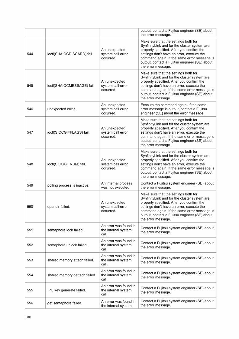
output, contact a Fujitsu engineer (SE) about the error message.
544 ioctl(SHAIOCDISCARD) fail. An unexpected system call error occurred.
Make sure that the settings both for SynfinityLink and for the cluster system are properly specified. After you confirm the settings don't have an error, execute the command again. If the same error message is output, contact a Fujitsu engineer (SE) about the error message.
545 ioctl(SHAIOCMESSAGE) fail. An unexpected system call error occurred.
Make sure that the settings both for SynfinityLink and for the cluster system are properly specified. After you confirm the settings don't have an error, execute the command again. If the same error message is output, contact a Fujitsu engineer (SE) about the error message.
546 unexpected error. An unexpected system call error occurred.
Execute the command again. If the same error message is output, contact a Fujitsu engineer (SE) about the error message.
547 ioctl(SIOCGIFFLAGS) fail. An unexpected system call error occurred.
Make sure that the settings both for SynfinityLink and for the cluster system are properly specified. After you confirm the settings don't have an error, execute the command again. If the same error message is output, contact a Fujitsu engineer (SE) about the error message.
548 ioctl(SIOCGIFNUM) fail. An unexpected system call error occurred.
Make sure that the settings both for SynfinityLink and for the cluster system are properly specified. After you confirm the settings don't have an error, execute the command again. If the same error message is output, contact a Fujitsu engineer (SE) about the error message.
549 polling process is inactive. An internal process was not executed.
Contact a Fujitsu system engineer (SE) about the error message.
550 opendir failed. An unexpected system call error occurred.
Make sure that the settings both for SynfinityLink and for the cluster system are properly specified. After you confirm the settings don't have an error, execute the command again. If the same error message is output, contact a Fujitsu engineer (SE) about the error message.
551 semaphore lock failed. An error was found in the internal system call.
Contact a Fujitsu system engineer (SE) about the error message.
552 semaphore unlock failed. An error was found in the internal system call.
Contact a Fujitsu system engineer (SE) about the error message.
553 shared memory attach failed. An error was found in the internal system call.
Contact a Fujitsu system engineer (SE) about the error message.
554 shared memory dettach failed. An error was found in the internal system call.
Contact a Fujitsu system engineer (SE) about the error message.
555 IPC key generate failed. An error was found in the internal system call.
Contact a Fujitsu system engineer (SE) about the error message.
556 get semaphore failed. An error was found in the internal system
Contact a Fujitsu system engineer (SE) about the error message.
138

call.
557 get shared memory segment identifier failed.
An error was found in the internal system call.
Contact a Fujitsu system engineer (SE) about the error message.
558 control semaphore failed. An error was found in the internal system call.
Contact a Fujitsu system engineer (SE) about the error message.
559 internal error. An internal error occurred.
Contact a Fujitsu system engineer (SE) about the error message.
560 control shared memory failed. An error was found in the internal system call.
Contact a Fujitsu system engineer (SE) about the error message.
561 daemon process is not exist. An internal error occurred.
Contact a Fujitsu system engineer (SE) about the error message.
562 failed to alloc memory. Failed to acquire memory.
Contact a Fujitsu system engineer (SE) about the error message.
563 failed to activate logicalIP. (%s) An internal error occurred.
Contact a Fujitsu system engineer (SE) about the error message.
564 failed to inactivate logicalIP. (%s)
An internal error occurred.
Contact a Fujitsu system engineer (SE) about the error message.
565 ioctl(SHAIOCPATROLL) fail. An error was found in the internal system call.
Execute the command again. If the same error message is output, contact a Fujitsu system engineer (SE) about the error message.
566 ether_aton() fail. An error was found in the internal system call.
Make sure that the settings for SynfinityLink are properly specified. After you confirm the settings do not have an error, execute the command again. If the same error message is output, contact a Fujitsu system engineer (SE) about the error message.
A.1.3 Console output messages (numbers of 800)
The following describes the messages output on the console by SynfinityLink, explanation, and operator response.
[Message number 8xx]
Message number Message Meaning Action
Link Down at TRUNKING mode (interface on devicename, target=host_name)
An error occurred in the communication with the remote host system (host_name) using the physical interface (interface) controlled by the virtual interface (devicename) that is operating in the Fast switching mode.
Check whether an error has occurred on the communication path to the remote host system.
800
Link Down at RIP mode (target=host_name)
An error occurred in the communication with the remote host system (host_name).
Check whether an error has occurred on the communication path to the remote host system.
139

Link Up at TRUNKING mode (interface on devicename, target=host_name)
The communication with the remote host system (host_name) using the physical interface (interface) controlled by the virtual interface (devicename) is recovered.
No action is required.
801
Link Up at RIP mode (target=host_name)
The communication with the remote host system (host_name) is recovered.
No action is required.
802 file open failed. Failed to open the file. Contact a Fujitsu system engineer (SE) about the error message.
803 file read failed. Failed to read the file. Contact a Fujitsu system engineer (SE) about the error message.
804 pipe create failed. Failed to create the internal communication pipe.
Contact a Fujitsu system engineer (SE) about the error message.
805 internal error. An internal error occurred. Contact a Fujitsu system engineer (SE) about the error message.
806 cannot get my process id Failed to obtain the local process ID.
Contact a Fujitsu system engineer (SE) about the error message.
807 callback regist failed. Failed to register the cluster call back function.
Contact a Fujitsu system engineer (SE) about the error message.
808 resource attribute get failed. Failed to obtain the cluster resource attribute.
Contact a Fujitsu system engineer (SE) about the error message.
809 resource attribute set failed. Failed to set the cluster resource attribute.
Contact a Fujitsu system engineer (SE) about the error message.
810 node information get failed. Failed to obtain the cluster node information.
Contact a Fujitsu system engineer (SE) about the error message.
811 resource id get failed. Failed to obtain the cluster resource identifier.
Contact a Fujitsu system engineer (SE) about the error message.
812 resource information get failed. Failed to obtain the cluster resource information.
Contact a Fujitsu system engineer (SE) about the error message.
813 event parse failed. Failed to analyze the cluster event.
Contact a Fujitsu system engineer (SE) about the error message.
814 cannot up interface. Failed to up the virtual interface.
Contact a Fujitsu system engineer (SE) about the error message.
815 sha device open failed. Failed to open the "sha" driver.
Contact a Fujitsu system engineer (SE) about the error message.
816 ioctl(SHAIOCSETRSCMON) failed.
Failed to send the monitor start request.
Contact a Fujitsu system engineer (SE) about the error message.
817 ClOpen failed. The connection to the cluster failed.
Contact a Fujitsu system engineer (SE) about the error message.
818 ClStartEvent failed. Failed to start the cluster event.
Contact a Fujitsu system engineer (SE) about the error message.
819 ClGetEsFd failed. Failed to obtain the cluster communication FD.
Contact a Fujitsu system engineer (SE) about the error message.
820 ClDispatchEvent failed. Failed to dispatch the cluster event.
Contact a Fujitsu system engineer (SE) about the error message.
821 ClGetStat failed. Failed to obtain the cluster resource status.
Contact a Fujitsu system engineer (SE) about the error message.
822 no data in cluster event. No data was found in the Contact a Fujitsu system engineer (SE)
140

cluster event. about the error message.
823 ClSetStat failed. The cluster resource status could not be set.
Contact a Fujitsu system engineer (SE) about the error message.
824 directory open failed. Failed to open the directory.
Contact a Fujitsu system engineer (SE) about the error message.
825 signal send failed. Failed to send the signal. Contact a Fujitsu system engineer (SE) about the error message.
826 command can be executed only with super-user.
The execution-time authority is invalid.
Contact a Fujitsu system engineer (SE) about the error message.
827 could not allocate memory. Failed to obtain the memory.
Contact a Fujitsu system engineer (SE) about the error message.
828 fork failed. The fork () failed. Contact a Fujitsu system engineer (SE) about the error message.
829 child process execute failed. Failed to generate the child process.
Contact a Fujitsu system engineer (SE) about the error message.
830 getmsg failed. Failed to receive the data from the "sha" driver.
Contact a Fujitsu system engineer (SE) about the error message.
831 shared library address get failed.
Failed to obtain the shared library address.
Contact a Fujitsu system engineer (SE) about the error message.
832 poll failed. The poll () failed. Contact a Fujitsu system engineer (SE) about the error message.
833 ioctl(SHAIOCSETIPADDR) failed.
Failed to notify the IP address.
Contact a Fujitsu system engineer (SE) about the error message.
840
polling device name is not defined in configuration information. polling is not started.
The virtual interface name for router monitoring is not defined in the configuration information. Thus, the router monitoring function for this virtual interface cannot be enabled.
Define the virtual interface name for router monitoring in the configuration information. Then, activate the virtual interface and inactivate/activate the router monitoring function.
841
all polling device name is not defined in configuration information. polling is not started.
No virtual interface for router monitoring is defined in the configuration information. Thus, the router monitoring function cannot be enabled.
Define the virtual interface name for router monitoring in the configuration information. Then, activate the virtual interface and inactivate/activate the router monitoring function.
842 device mode is invalid. polling is not started.
The operation mode of a virtual interface for router monitoring is invalid. Thus, the router monitoring function for this virtual interface cannot be enabled.
The operation mode of the virtual interface for router monitoring is defined as Fast switching mode. In Fast switching mode, line monitoring with the router monitoring function cannot be performed. Delete from the monitoring destination information the virtual interfaces whose operation mode is Fast switching mode.
843 polling device is not specified. polling is not started.
No monitoring destination information is specified. Or specified monitoring destination information contains invalid an error. Thus, the router monitoring function cannot be enabled.
Specify the monitoring destination information. Or correct the error in the settings using the check command of hanetpoll. Then, disable and enable the router monitoring function.
844 polling address is invalid. polling is not started.
The monitoring destination address or host name
Correct the monitoring destination address specified in the monitoring
141

specified in the monitoring destination information is invalid. Thus, the router monitoring function cannot be enabled.
destination information. Then, disable and enable the router monitoring function.
845 could not restart in.routed.
Failed to restart the routing daemon. The router monitoring function is stopped and cluster switching is performed.
Make sure that the settings for the system, SynfinityLink, and cluster system are properly specified. If the same error message is output, contact a Fujitsu system engineer (SE) about the error message.
846 could not restart in.rdisc.
Failed to restart the router discovery daemon. The router monitoring function is stopped and cluster switching is performed.
Make sure that the settings for the system, SynfinityLink, and cluster system are properly specified. If the same error message is output, contact a Fujitsu system engineer (SE) about the error message.
847 internal error retry over. polling stop.
A router monitoring internal error occurred. The router monitoring is stopped.
Make sure that the settings for the system, SynfinityLink, and cluster system are properly specified. If the same error message is output, contact a Fujitsu system engineer (SE) about the error message.
848 device is inactive. polling stop.
The virtual interface for router monitoring is not activated. The router monitoring function is disabled.
Activate the virtual interface. Then, inactivate and activate the router monitoring function. This message may be displayed when cluster switching occurs during cluster operation, but in this case, no action is needed.
849 poll fail retry over. polling stop.
The transmission line failed as many times as specified by the retry count consecutively. The router monitoring function is disabled.
Check the line failure. After checking the line recovery, inactivate and activate the router monitoring function.
850 cannot down interface. Failed to inactivate the physical interface.
Make sure that the settings for SynfinityLink and the system are properly specified. If no problem is found, contact a Fujitsu system engineer (SE) about the error message.
851 primary polling failed. lip=logicalIP, target=pollip.
An error of path to the primary monitoring destination was detected in the initial check of the physical interface.
LogicalIP: Logical IP Pollip: Monitoring destination IP
Check for any failure on the communication path to the monitoring destination.
852 secondry polling failed. lip=logicalIP, target=pollip.
An error of path to the secondary monitoring destination was detected in the initial check of the physical interface. LogicalIP: Logical IP, pollip: Monitoring destination IP
Check for any failure on the communication path to the monitoring destination.
853 phisical interface up failed. Failed to activate a physical interface.
Make sure that the settings for SynfinityLink and the system are properly specified. If no problem is found, contact a Fujitsu system engineer (SE) about the error message.
142

854 logical interface up failed. Failed to activate a logical interface.
Make sure that the settings for SynfinityLink and the system are properly specified. If no problem is found, contact a Fujitsu system engineer (SE) about the error message.
855 cluster logical interface is not found.
The logical interface registered with the cluster was not found.
Make sure that the settings for SynfinityLink, the cluster system, and system are properly specified. If no problem is found, contact a Fujitsu system engineer (SE) about the error message.
856 cluster configuration is incomplete.
The logical IP address cannot be activated because the cluster settings are incomplete.
Review the cluster system settings, and reboot the system
857 polling information is not defined.
Monitoring destination information is not defined.
Define monitoring destination information using the hanetpoll command.
870 polling status changed: primary polling failed. (ifname,target=pollip)
Line monitoring on the primary side failed. ifname: Interface name, pollip: Monitoring destination address
Check for any failure on the communication path to the monitoring destination.
871 polling status changed: secondary polling failed. (ifname,target=pollip)
Line monitoring on the secondary side failed. ifname: Interface name, pollip: Monitoring destination address
Check for any failure on the communication path to the monitoring destination. If monitoring stopped after checking the recovery of the communication path, make a router/HUB monitoring function invalid and valid using the hanetpoll command. If monitoring fails even though possible to communicate normally, tune the intervals and the number of the times of monitoring, and the time to wait for a linkup with the hanetpoll command.
872
polling status changed: primaryHUB to secondaryHUB polling failed. (ifname,target=pollip)
HUB-HUB communication monitoring on the primary side failed. ifname: Interface name, pollip: Monitoring destination address
Check for any failure on the communication path to the monitoring destination.
873
polling status changed: secondaryHUB to primaryHUB polling failed. (ifname,target=pollip)
HUB-HUB communication monitoring on the secondary side failed. ifname: Interface name, pollip: Monitoring destination address
Check for any failure on the communication path to the monitoring destination.
874 polling status changed: HUB repair (target=pollip)
Line failure in HUB-HUB communication monitoring was repaired. pollip: Monitoring destination address
No action is required.
875 standby interface failed.(ifname)
An error involving standby interface was detected in the standby patrol. ifname: Interface name
Check the status of the standby interface.
876 node status is noticed.(sourceip:status)
A node status change was notified from the remote system. sourceip: Source address, status: Notified
Check the status of the source.
143
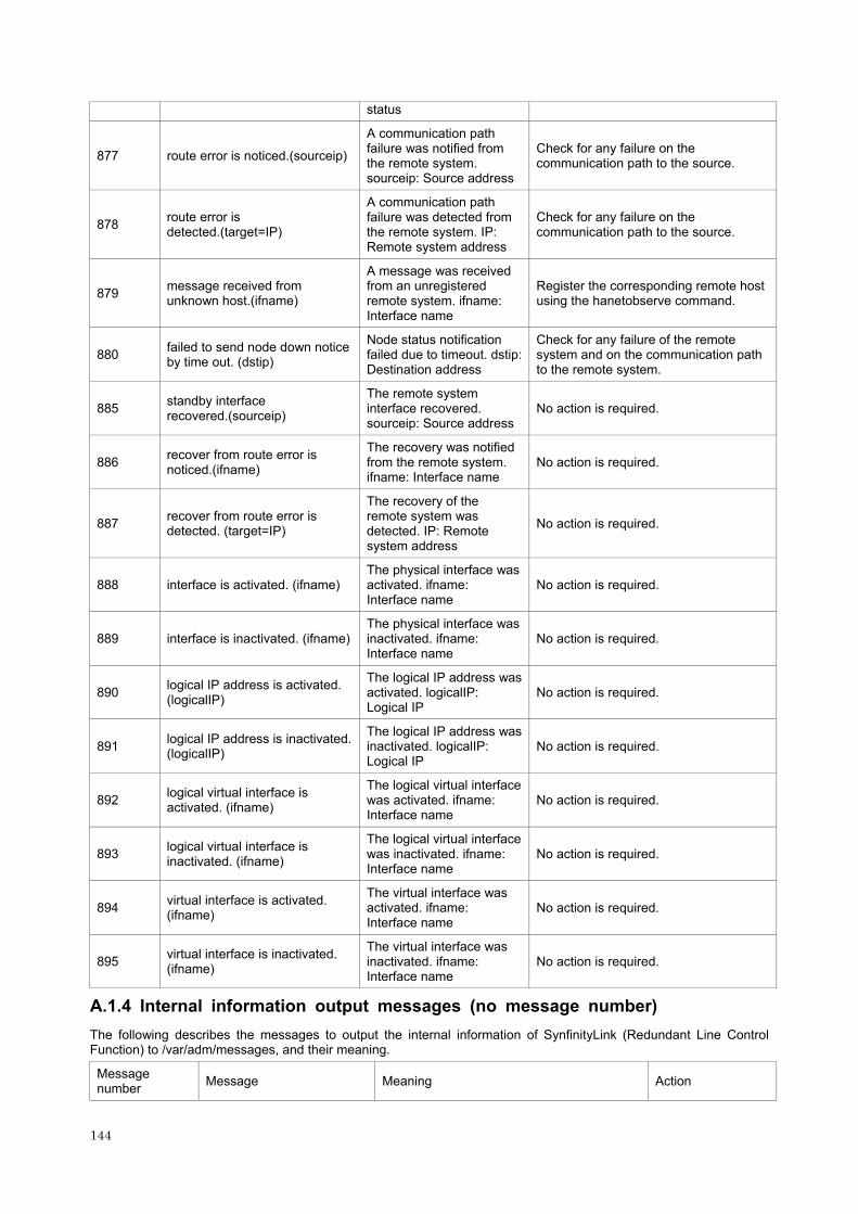
status
877 route error is noticed.(sourceip)
A communication path failure was notified from the remote system. sourceip: Source address
Check for any failure on the communication path to the source.
878 route error is detected.(target=IP)
A communication path failure was detected from the remote system. IP: Remote system address
Check for any failure on the communication path to the source.
879 message received from unknown host.(ifname)
A message was received from an unregistered remote system. ifname: Interface name
Register the corresponding remote host using the hanetobserve command.
880 failed to send node down notice by time out. (dstip)
Node status notification failed due to timeout. dstip: Destination address
Check for any failure of the remote system and on the communication path to the remote system.
885 standby interface recovered.(sourceip)
The remote system interface recovered. sourceip: Source address
No action is required.
886 recover from route error is noticed.(ifname)
The recovery was notified from the remote system. ifname: Interface name
No action is required.
887 recover from route error is detected. (target=IP)
The recovery of the remote system was detected. IP: Remote system address
No action is required.
888 interface is activated. (ifname) The physical interface was activated. ifname: Interface name
No action is required.
889 interface is inactivated. (ifname) The physical interface was inactivated. ifname: Interface name
No action is required.
890 logical IP address is activated. (logicalIP)
The logical IP address was activated. logicalIP: Logical IP
No action is required.
891 logical IP address is inactivated. (logicalIP)
The logical IP address was inactivated. logicalIP: Logical IP
No action is required.
892 logical virtual interface is activated. (ifname)
The logical virtual interface was activated. ifname: Interface name
No action is required.
893 logical virtual interface is inactivated. (ifname)
The logical virtual interface was inactivated. ifname: Interface name
No action is required.
894 virtual interface is activated. (ifname)
The virtual interface was activated. ifname: Interface name
No action is required.
895 virtual interface is inactivated. (ifname)
The virtual interface was inactivated. ifname: Interface name
No action is required.
A.1.4 Internal information output messages (no message number)
The following describes the messages to output the internal information of SynfinityLink (Redundant Line Control Function) to /var/adm/messages, and their meaning.
Message number Message Meaning Action
144

- update cluster resource status. To update the state of the cluster resources. No action is
required.
- update cluster resource status. Received a message from an SHA driver. No action is
required.
- receive event from cluster: Received an event from the cluster management.
No action is required.
- polling To control a monitoring function. No action is required.
- in.routed killed. To terminate an in.routed daemon process. No action is required.
- in.rdisc killed. To terminate an in.rdisc daemon process. No action is required.
- child proc exit. A monitoring process terminated. No action is required.
145

146

Appendix B Examples of Setting Up
The local IP address is used for the IP address in this definition example.
B.1 Example of Setting up the Redundant Operation by Fast switching mode
B.1.1 Example of the Single system
This section provides an example of setting up in the following network configuration.
[HOST-A]
1) Setting up the Virtual interface
/opt/FJSVhanet/usr/sbin/hanetconfig create -n sha0 -m t -i 192.13.80.1 -t hme0,hme1
2) Separately activating Virtual interfaces
/opt/FJSVhanet/usr/sbin/strhanet -n sha0
[HOST-B]
1) Setting up the Virtual interface
/opt/FJSVhanet/usr/sbin/hanetconfig create -n sha0 -m t -i 192.13.80.2 -t hme0,hme1
2) Separately activating the Virtual interfaces
/opt/FJSVhanet/usr/sbin/strhanet -n sha0
B.1.2 Example of the Single system in Logical Virtual interface
This section provides an example of setting up in the following network configuration.
147

[HOST-A]
1) Setting up the Virtual interface
/opt/FJSVhanet/usr/sbin/hanetconfig create -n sha0 -m t -i 192.13.80.1 -t hme0,hme1
2) Setting up the Logical Virtual interface
/opt/FJSVhanet/usr/sbin/hanetconfig create -n sha0:2 -i 192.13.80.3
[HOST-B]
1) Setting up the Virtual interface
/opt/FJSVhanet/usr/sbin/hanetconfig create -n sha0 -m t -i 192.13.80.2 -t hme0,hme1
2) Separately activating the Virtual interfaces
/opt/FJSVhanet/usr/sbin/strhanet -n sha0
B.1.3 Example of the Cluster system (Standby mode)
This section provides an example of setting up in the following network configuration. See such as a Cluster system manual as to the initial setting of a Cluster system and configure it. Omitted a description of a private LAN.
148

[HOST-A]
1) Setting up the Virtual interface
/opt/FJSVhanet/usr/sbin/hanetconfig create -n sha0 -m t -i 192.13.80.1 -t hme0,hme1
2) Setting up the Cluster configuration
2-1) Registering resource
To register the resources to a Cluster system. /opt/FJSVhanet/sys/claddhanetrsc -n sha0
2-2) Setting up the takeover IP address
To execute after completed "2-1) Registering resource" in HOST-B. /opt/FJSVhanet/sys/claddhanetiprsc -n sha0 -i 192.13.80.3
2-3) Registering Cluster service
To register a service from a Cluster Management View.
2-4) Setting up the Cluster service
/opt/FJSVhanet/sys/claddhanetsvc -n sha0
3) Rebooting
When setting up of the HOST-A and HOST-B is complete, reboot both nodes simultaneously.
[HOST-B]
1) Setting up the Virtual interface
/opt/FJSVhanet/usr/sbin/hanetconfig create -n sha0 -m t -i 192.13.80.2 -t hme0,hme1
2) Setting up the Cluster configuration
2-1) Registering resource
To register the resources to a Cluster system. /opt/FJSVhanet/sys/claddhanetrsc -n sha0
149

3) Rebooting
B.1.4 Example of the Cluster system (Mutual standby mode)
This section provides an example of setting up in the following network configuration. See such as a Cluster system manual as to the initial setting of a Cluster system and configure it. Omitted a description of a private LAN.
[HOST-A]
1) Setting up the Virtual interface
/opt/FJSVhanet/usr/sbin/hanetconfig create -n sha0 -m t -i 192.13.80.1 -t hme0,hme1
2) Setting up the Cluster configuration
2-1) Registering resource
To register the resources to a Cluster system. /opt/FJSVhanet/sys/claddhanetrsc -n sha0
2-2) Setting up the takeover IP address
To execute after completed "2-1) Registering resource" in HOST-B. /opt/FJSVhanet/sys/claddhanetiprsc -n sha0 -i 192.13.80.10 /opt/FJSVhanet/sys/claddhanetiprsc -n sha0 -i 192.13.80.20
2-3) Registering Cluster service
To register a service from a Cluster Management View.
150

2-4) Setting up the Cluster service
To set a Virtual IP address for Service1 and Service2 respectively. /opt/FJSVhanet/sys/claddhanetsvc -n sha0 -k 192.13.80.10 /opt/FJSVhanet/sys/claddhanetsvc -n sha0 -k 192.13.80.20
3) Rebooting
When setting up of the HOST-A and HOST-B is complete, reboot both nodes simultaneously.
[HOST-B]
1) Setting up the Virtual interface
/opt/FJSVhanet/usr/sbin/hanetconfig create -n sha0 -m t -i 192.13.80.2 -t hme0,hme1
2) Setting up the Cluster configuration
2-1) Registering resource
To register the resources to a Cluster system. /opt/FJSVhanet/sys/claddhanetrsc -n sha0
3) Rebooting
When setting up of the HOST-A and HOST-B is complete, reboot both nodes simultaneously.
B.1.5 Example of the Cluster system (2:1 standby mode)
This section provides an example of setting up in the following network configuration. See such as a Cluster system manual as to the initial setting of a Cluster system and configure it. Omitted a description of a private LAN.
151

[HOST-A]
1) Setting up the Virtual interface
/opt/FJSVhanet/usr/sbin/hanetconfig create -n sha0 -m t -i 192.13.80.1 -t hme0,hme1
2) Setting up the Cluster configuration
2-1) Registering resource
To register the resources to a Cluster system. /opt/FJSVhanet/sys/claddhanetrsc -n sha0
3) Rebooting
When setting up of the HOST-A, HOST-B and HOST-C is complete, reboot both nodes simultaneously.
[HOST-B]
1) Setting up the Virtual interface
/opt/FJSVhanet/usr/sbin/hanetconfig create -n sha0 -m t -i 192.13.80.2 -t hme0,hme1
2) Setting up the Cluster configuration
2-1) Registering resource
To register the resources to a Cluster system. /opt/FJSVhanet/sys/claddhanetrsc -n sha0
3) Rebooting
When setting up of the HOST-A, HOST-B and HOST-C is complete, reboot both nodes simultaneously.
[HOST-C]
1) Setting up the Virtual interface
/opt/FJSVhanet/usr/sbin/hanetconfig create -n sha0 -m t -i 192.13.80.3 -t hme0,hme1
2) Setting up the Cluster configuration
2-1) Registering resource
To register the resources to a Cluster system. /opt/FJSVhanet/sys/claddhanetrsc -n sha0
2-2) Setting up the takeover IP address
To execute after completed "2-1) Registering resource" in HOST-A and HOST-B. /opt/FJSVhanet/sys/claddhanetiprsc -n sha0 -i 192.13.80.10 -d HOST-A /opt/FJSVhanet/sys/claddhanetiprsc -n sha0 -i 192.13.80.20 -d HOST-B
2-3) Registering Cluster service
To register a service from a Cluster Management View.
2-4) Setting up the Cluster service
To set a Virtual IP address for Service1 and Service2 respectively. /opt/FJSVhanet/sys/claddhanetsvc -n sha0 -k 192.13.80.10 /opt/FJSVhanet/sys/claddhanetsvc -n sha0 -k 192.13.80.20
3) Rebooting
When setting up of the HOST-A, HOST-B and HOST-C is complete, reboot both nodes simultaneously.
152

B.2 Example of Setting up the Redundant Operation by RIP mode
B.2.1 Example of the Single system
This section provides an example of setting up in the following network configuration. If the router monitoring function is not used, omit 2) and 4) in the procedure for setting up on each host.
[HOST-A]
1) Setting up the Virtual interface
/opt/FJSVhanet/usr/sbin/hanetconfig create -n sha0 -m r -i 192.13.80.1 -t hme0,hme1
2) Setting up the Router monitoring function
/opt/FJSVhanet/usr/sbin/hanetpoll create -n sha0 -p A,C
153
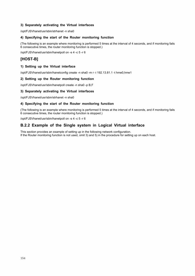
3) Separately activating the Virtual interfaces
/opt/FJSVhanet/usr/sbin/strhanet -n sha0
4) Specifying the start of the Router monitoring function
(The following is an example where monitoring is performed 5 times at the interval of 4 seconds, and if monitoring fails 6 consecutive times, the router monitoring function is stopped.)
/opt/FJSVhanet/usr/sbin/hanetpoll on -s 4 -c 5 -r 6
[HOST-B]
1) Setting up the Virtual interface
/opt/FJSVhanet/usr/sbin/hanetconfig create -n sha0 -m r -i 192.13.81.1 -t hme0,hme1
2) Setting up the Router monitoring function
/opt/FJSVhanet/usr/sbin/hanetpoll create -n sha0 -p B,F
3) Separately activating the Virtual interfaces
/opt/FJSVhanet/usr/sbin/strhanet -n sha0
4) Specifying the start of the Router monitoring function
(The following is an example where monitoring is performed 5 times at the interval of 4 seconds, and if monitoring fails 6 consecutive times, the router monitoring function is stopped.)
/opt/FJSVhanet/usr/sbin/hanetpoll on -s 4 -c 5 -r 6
B.2.2 Example of the Single system in Logical Virtual interface
This section provides an example of setting up in the following network configuration. If the Router monitoring function is not used, omit 3) and 5) in the procedure for setting up on each host.
154

[HOST-A]
1) Setting up the Virtual interface
/opt/FJSVhanet/usr/sbin/hanetconfig create -n sha0 -m r -i 192.13.80.1 -t hme0,hme1
2) Setting up the Logical Virtual interface
/opt/FJSVhanet/usr/sbin/hanetconfig create -n sha0:2 -i 192.13.80.3
3) Setting up the Router monitoring function
/opt/FJSVhanet/usr/sbin/hanetpoll create -n sha0 -p A,C
4) Separately activating the Virtual interfaces
/opt/FJSVhanet/usr/sbin/strhanet -n sha0
5) Specifying the start of the Router monitoring function
(To monitor every four seconds. To stop a router monitoring function if failed six times in succession. The example is shown below.) /opt/FJSVhanet/usr/sbin/hanetpoll on -s 4 -c 5 -r 6
155
[HOST-B]
1) Setting up the Remote system
A system possible to use is optional, and its setting of the system network environment is executed.
B.2.3 Example of the Cluster system (Standby mode)
See the appendix B.3.3.
B.3 Example of Setting up the Fast switching/RIP mode
B.3.1 Example of the Single system
See the appendix B.1.1 and appendix B.2.1.
B.3.2 Example of the Single system in Logical Virtual interface
See the appendix B.1.2 and appendix B.2.2.
B.3.3 Example of the Cluster system (Standby mode)
This section provides an example of setting up in the following network configuration. To omit the setting procedure 3) for HOST-A and HOST-B, and 2) and 4) for HOST-C when not using a Router monitoring function.
156

[HOST-A]
1) Setting up the Virtual interface
/opt/FJSVhanet/usr/sbin/hanetconfig create -n sha0 -m b -i 192.13.80.2 -t hme0,hme1
2) Setting up the Cluster configuration
2-1) Registering resource
To register the resources to a Cluster system. /opt/FJSVhanet/sys/claddhanetrsc -n sha0
2-2) Setting up the takeover IP address
To execute after completed "2-1) Registering resource" in HOST-B.
157

/opt/FJSVhanet/sys/claddhanetiprsc -n sha0 -i 192.13.80.1
2-3) Registering Cluster service
To register a service from a Cluster Management View.
2-4) Setting up the Cluster service
To set a Virtual IP address for Service1. /opt/FJSVhanet/sys/claddhanetsvc -n sha0
3) Setting up the Router monitoring function
/opt/FJSVhanet/usr/sbin/hanetpoll create -n sha0 -p A,C
4) Rebooting
When setting up of the HOST-A and HOST-B is complete, reboot both nodes simultaneously.
[HOST-B]
1) Setting up the Virtual interface
/opt/FJSVhanet/usr/sbin/hanetconfig create -n sha0 -m b -i 192.13.80.3 -t hme0,hme1
2) Setting up the Cluster configuration
2-1) Registering resource
To register the resources to a Cluster system. /opt/FJSVhanet/sys/claddhanetrsc -n sha0
3) Setting up the Router monitoring function
/opt/FJSVhanet/usr/sbin/hanetpoll create -n sha0 -p A,C
4) Rebooting
When setting up of the HOST-A and HOST-B is complete, reboot both nodes simultaneously.
[HOST-C]
1) Setting up the Virtual interface
/opt/FJSVhanet/usr/sbin/hanetconfig create -n sha0 -m r -i 192.13.81.1 -t hme0,hme1
2) Setting up the Router monitoring function
/opt/FJSVhanet/usr/sbin/hanetpoll create -n sha0 -p B,F
3) Separately activating the Virtual interfaces
/opt/FJSVhanet/usr/sbin/strhanet -n sha0
4) Specifying the start of the Router monitoring function
(To monitor every four seconds. To stop a router monitoring function if failed six times in succession. The example is shown below.) /opt/FJSVhanet/usr/sbin/hanetpoll on -s 4 -c 5 -r 6
B.4 Example of Setting up the NIC switching mode
B.4.1 Example of the Single system without NIC sharing
This section provides an example of setting up in the following network configuration. If the Standby patrol monitoring function is not used, omit 3) in the procedure for setting up on each host.
158

[HOST-A]
1) Setting up the Virtual interface
/opt/FJSVhanet/usr/sbin/hanetconfig create -n sha0 -m d -i 192.13.70.1 -e 192.13.70.2 -t hme0,hme1
2) Setting up the HUB-HUB monitoring function
/opt/FJSVhanet/usr/sbin/hanetpoll create -n sha0 -p 192.13.70.100,192.13.70.101 -b on
3) Setting up the Standby patrol monitoring function
/opt/FJSVhanet/usr/sbin/hanetconfig create -n sha1 -m p -a 02:00:00:00:00:00 -t sha0
4) Rebooting
When setting up of the HOST-A and HOST-B is complete, reboot both nodes simultaneously.
[HOST-B]
1) Setting up the Virtual interface
/opt/FJSVhanet/usr/sbin/hanetconfig create -n sha0 -m d -i 192.13.70.3 -e 192.13.70.4 -t hme0,hme1
2) Setting up the HUB-HUB monitoring function
/opt/FJSVhanet/usr/sbin/hanetpoll create -n sha0 -p 192.13.70.100,192.13.70.101 -b on
3) Setting up the Standby patrol monitoring function
/opt/FJSVhanet/usr/sbin/hanetconfig create -n sha1 -m p -a 02:00:00:00:00:01 -t sha0
4) Rebooting
When setting up of the HOST-A and HOST-B is complete, reboot both nodes simultaneously.
B.4.2 Example of the Single system with NIC sharing
This section provides an example of setting up in the following network configuration. If the Standby patrol monitoring function is not used, omit 3) in the procedure for setting up on each host.
159

[HOST-A]
1) Setting up the Virtual interface
/opt/FJSVhanet/usr/sbin/hanetconfig create -n sha0 -m d -i 192.13.70.1 -e 192.13.70.3 -t hme0,hme1 /opt/FJSVhanet/usr/sbin/hanetconfig copy -n sha0,sha1 -i 192.13.70.2
2) Setting up the HUB-HUB monitoring function
/opt/FJSVhanet/usr/sbin/hanetpoll create -n sha0 -p 192.13.70.100,192.13.70.101 -b on /opt/FJSVhanet/usr/sbin/hanetpoll copy -n sha0,sha1
3) Setting up the Standby patrol monitoring function
/opt/FJSVhanet/usr/sbin/hanetconfig create -n sha2 -m p -a 02:00:00:00:00:00 -t sha0
4) Rebooting
When setting up of the HOST-A and HOST-B is complete, reboot both nodes simultaneously.
[HOST-B]
1) Setting up the Virtual interface
/opt/FJSVhanet/usr/sbin/hanetconfig create -n sha0 -m d -i 192.13.70.4 -e 192.13.70.6 -t hme0,hme1 /opt/FJSVhanet/usr/sbin/hanetconfig copy -n sha0,sha1 -i 192.13.70.5
160

2) Setting up the HUB-HUB monitoring function
/opt/FJSVhanet/usr/sbin/hanetpoll create -n sha0 -p 192.13.70.100,192.13.70.101 -b on /opt/FJSVhanet/usr/sbin/hanetpoll copy -n sha0,sha1
3) Setting up the Standby patrol monitoring function
/opt/FJSVhanet/usr/sbin/hanetconfig create -n sha2 -m p -a 02:00:00:00:00:02 -t sha0
4) Rebooting
When setting up of the HOST-A and HOST-B is complete, reboot both nodes simultaneously.
B.4.3 Example of the Cluster system (Standby mode) without NIC sharing
This section provides an example of setting up in the following network configuration. See such as a Cluster system manual as to the initial setting of a Cluster system and configure it. Omitted a description of a private LAN. If the Standby patrol monitoring function is not used, omit 3) in the procedure for setting up on each host.
[HOST-A]
1) Setting up the Virtual interface
/opt/FJSVhanet/usr/sbin/hanetconfig create -n sha0 -m d -i 192.13.70.1 -e 192.13.70.2 -t hme0,hme1
2) Setting up the HUB-HUB monitoring function
/opt/FJSVhanet/usr/sbin/hanetpoll create -n sha0 -p 192.13.70.100,192.13.70.101 -b on
3) Setting up the Standby patrol monitoring function
/opt/FJSVhanet/usr/sbin/hanetconfig create -n sha1 -m p -a 02:00:00:00:00:00 -t sha0
161
4) Setting up the Cluster configuration
4-1) Registering resource
To register the resources to a Cluster system. /opt/FJSVhanet/sys/claddhanetrsc -n sha0
4-2) Setting up the takeover IP address
To execute after completed "4-1) Registering resource" in HOST-B. /opt/FJSVhanet/sys/claddhanetiprsc -n sha0
4-3) Registering Cluster service
To register a service from a Cluster Management View.
4-4) Setting up the Cluster service
/opt/FJSVhanet/sys/claddhanetsvc -n sha0
5) Rebooting
When setting up of the HOST-A and HOST-B is complete, reboot both nodes simultaneously.
[HOST-B]
1) Setting up the Virtual interface
/opt/FJSVhanet/usr/sbin/hanetconfig create -n sha0 -m d -i 192.13.70.1 -e 192.13.70.3 -t hme0,hme1
2) Setting up the HUB-HUB monitoring function
/opt/FJSVhanet/usr/sbin/hanetpoll create -n sha0 -p 192.13.70.100,192.13.70.101 -b on
3) Setting up the Standby patrol monitoring function
/opt/FJSVhanet/usr/sbin/hanetconfig create -n sha1 -m p -a 02:00:00:00:00:01 -t sha0
4) Setting up the Cluster configuration
4-1) Registering resource
To register the resources to a Cluster system. /opt/FJSVhanet/sys/claddhanetrsc -n sha0
5) Rebooting
When setting up of the HOST-A and HOST-B is complete, reboot both nodes simultaneously.
B.4.4 Example of the Cluster system (Mutual standby mode) without NIC sharing
This section provides an example of setting up in the following network configuration. See such as a Cluster system manual as to the initial setting of a Cluster system and configure it. Omitted a description of a private LAN. If the Standby patrol monitoring function is not used, omit 3) in the procedure for setting up on each host.
162

[HOST-A]
1) Setting up the Virtual interface
/opt/FJSVhanet/usr/sbin/hanetconfig create -n sha0 -m d -i 192.13.70.1 -e 192.13.70.2 -t hme0,hme1 /opt/FJSVhanet/usr/sbin/hanetconfig create -n sha0 -m d -i 192.13.71.1 -e 192.13.71.2 -t hme2,hme3
2) Setting up the HUB-HUB monitoring function
/opt/FJSVhanet/usr/sbin/hanetpoll create -n sha0 -p 192.13.70.100,192.13.70.101 -b on /opt/FJSVhanet/usr/sbin/hanetpoll create -n sha1 -p 192.13.71.100,192.13.71.101 -b on
3) Setting up the Standby patrol monitoring function
/opt/FJSVhanet/usr/sbin/hanetconfig create -n sha2 -m p -a 02:00:00:00:00:00 -t sha0 /opt/FJSVhanet/usr/sbin/hanetconfig create -n sha3 -m p -a 02:00:00:00:00:01 -t sha1
4) Setting up the Cluster configuration
4-1) Registering resource
To register the resources to a Cluster system. /opt/FJSVhanet/sys/claddhanetrsc -n sha0 /opt/FJSVhanet/sys/claddhanetrsc -n sha1
4-2) Setting up the takeover IP address
To execute after completed "4-1) Registering resource" in HOST-B. /opt/FJSVhanet/sys/claddhanetiprsc -n sha0 /opt/FJSVhanet/sys/claddhanetiprsc -n sha1
4-3) Registering Cluster service
To register a service from a Cluster Management View.
4-4) Setting up the Cluster service
/opt/FJSVhanet/sys/claddhanetsvc -n sha0
163

/opt/FJSVhanet/sys/claddhanetsvc -n sha1
5) Rebooting
When setting up of the HOST-A and HOST-B is complete, reboot both nodes simultaneously.
[HOST-B]
1) Setting up the Virtual interface
/opt/FJSVhanet/usr/sbin/hanetconfig create -n sha0 -m d -i 192.13.70.1 -e 192.13.70.3 -t hme0,hme1 /opt/FJSVhanet/usr/sbin/hanetconfig create -n sha0 -m d -i 192.13.71.1 -e 192.13.71.3 -t hme2,hme3
2) Setting up the HUB-HUB monitoring function
/opt/FJSVhanet/usr/sbin/hanetpoll create -n sha0 -p 192.13.70.100,192.13.70.101 -b on /opt/FJSVhanet/usr/sbin/hanetpoll create -n sha1 -p 192.13.71.100,192.13.71.101 -b on
3) Setting up the Standby patrol monitoring function
/opt/FJSVhanet/usr/sbin/hanetconfig create -n sha2 -m p -a 02:00:00:00:00:02 -t sha0 /opt/FJSVhanet/usr/sbin/hanetconfig create -n sha3 -m p -a 02:00:00:00:00:03 -t sha1
4) Setting up the Cluster configuration
4-1) Registering resource
To register the resources to a Cluster system. /opt/FJSVhanet/sys/claddhanetrsc -n sha0 /opt/FJSVhanet/sys/claddhanetrsc -n sha1
5) Rebooting
When setting up of the HOST-A and HOST-B is complete, reboot both nodes simultaneously.
B.4.5 Example of the Cluster system in takeover physical IP address (part 1)
This section provides an example of setting up in the following network configuration (Activation Physical interface on the Standby node). If the Standby patrol monitoring function is not used, omit 3) in the procedure for setting up on each host.
164
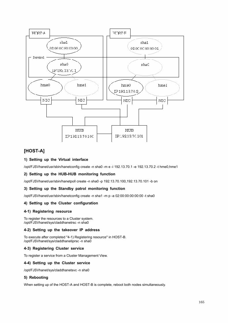
[HOST-A]
1) Setting up the Virtual interface
/opt/FJSVhanet/usr/sbin/hanetconfig create -n sha0 -m e -i 192.13.70.1 -e 192.13.70.2 -t hme0,hme1
2) Setting up the HUB-HUB monitoring function
/opt/FJSVhanet/usr/sbin/hanetpoll create -n sha0 -p 192.13.70.100,192.13.70.101 -b on
3) Setting up the Standby patrol monitoring function
/opt/FJSVhanet/usr/sbin/hanetconfig create -n sha1 -m p -a 02:00:00:00:00:00 -t sha0
4) Setting up the Cluster configuration
4-1) Registering resource
To register the resources to a Cluster system. /opt/FJSVhanet/sys/claddhanetrsc -n sha0
4-2) Setting up the takeover IP address
To execute after completed "4-1) Registering resource" in HOST-B. /opt/FJSVhanet/sys/claddhanetiprsc -n sha0
4-3) Registering Cluster service
To register a service from a Cluster Management View.
4-4) Setting up the Cluster service
/opt/FJSVhanet/sys/claddhanetsvc -n sha0
5) Rebooting
When setting up of the HOST-A and HOST-B is complete, reboot both nodes simultaneously.
165

[HOST-B]
1) Setting up the Virtual interface
/opt/FJSVhanet/usr/sbin/hanetconfig create -n sha0 -m e -i 192.13.70.1 -e 192.13.70.3 -t hme0,hme1
2) Setting up the HUB-HUB monitoring function
/opt/FJSVhanet/usr/sbin/hanetpoll create -n sha0 -p 192.13.70.100,192.13.70.101 -b on
3) Setting up the Standby patrol monitoring function
/opt/FJSVhanet/usr/sbin/hanetconfig create -n sha1 -m p -a 02:00:00:00:00:01 -t sha0
4) Setting up the Cluster configuration
4-1) Registering resource
To register the resources to a Cluster system. /opt/FJSVhanet/sys/claddhanetrsc -n sha0
5) Rebooting
When setting up of the HOST-A and HOST-B is complete, reboot both nodes simultaneously.
B.4.6 Example of the Cluster system in takeover physical IP address (part 2)
This section provides an example of setting up in the following network configuration (Not activation Physical interface on the Standby node). If the Standby patrol monitoring function is not used, omit 3) in the procedure for setting up on each host.
[HOST-A]
1) Setting up the Virtual interface
/opt/FJSVhanet/usr/sbin/hanetconfig create -n sha0 -m e -i 192.13.70.1 -t hme0,hme1
166
2) Setting up the HUB-HUB monitoring function
/opt/FJSVhanet/usr/sbin/hanetpoll create -n sha0 -p 192.13.70.100,192.13.70.101 -b on
3) Setting up the Standby patrol monitoring function
/opt/FJSVhanet/usr/sbin/hanetconfig create -n sha1 -m p -a 02:00:00:00:00:00 -t sha0
4) Setting up the Cluster configuration
4-1) Registering resource
To register the resources to a Cluster system. /opt/FJSVhanet/sys/claddhanetrsc -n sha0
4-2) Setting up the takeover IP address
To execute after completed "4-1) Registering resource" in HOST-B. /opt/FJSVhanet/sys/claddhanetiprsc -n sha0
4-3) Registering Cluster service
To register a service from a Cluster Management View.
4-4) Setting up the Cluster service
/opt/FJSVhanet/sys/claddhanetsvc -n sha0
5) Rebooting
When setting up of the HOST-A and HOST-B is complete, reboot both nodes simultaneously.
[HOST-B]
1) Setting up the Virtual interface
/opt/FJSVhanet/usr/sbin/hanetconfig create -n sha0 -m e -i 192.13.70.1 -t hme0,hme1
2) Setting up the HUB-HUB monitoring function
/opt/FJSVhanet/usr/sbin/hanetpoll create -n sha0 -p 192.13.70.100,192.13.70.101 -b on
3) Setting up the Standby patrol monitoring function
/opt/FJSVhanet/usr/sbin/hanetconfig create -n sha1 -m p -a 02:00:00:00:00:01 -t sha0
4) Setting up the Cluster configuration
4-1) Registering resource
To register the resources to a Cluster system. /opt/FJSVhanet/sys/claddhanetrsc -n sha0
5) Rebooting
When setting up of the HOST-A and HOST-B is complete, reboot both nodes simultaneously.
B.4.7 Example of the Cluster system (Mutual standby mode) with NIC sharing
This section provides an example of setting up in the following network configuration. See such as a Cluster system manual as to the initial setting of a Cluster system and configure it. Omitted a description of a private LAN. If the Standby patrol monitoring function is not used, omit 3) in the procedure for setting up on each host.
167

[HOST-A]
1) Setting up the Virtual interface
/opt/FJSVhanet/usr/sbin/hanetconfig create -n sha0 -m d -i 192.13.70.1 -e 192.13.70.3 -t hme0,hme1 /opt/FJSVhanet/usr/sbin/hanetconfig copy -n sha0,sha1 -i 192.13.70.2
2) Setting up the HUB-HUB monitoring function
/opt/FJSVhanet/usr/sbin/hanetpoll create -n sha0 -p 192.13.70.100,192.13.70.101 -b on /opt/FJSVhanet/usr/sbin/hanetpoll copy -n sha0,sha1
3) Setting up the Standby patrol monitoring function
/opt/FJSVhanet/usr/sbin/hanetconfig create -n sha2 -m p -a 02:00:00:00:00:00 -t sha0
4) Setting up the Cluster configuration
4-1) Registering resource
To register the resources to a Cluster system. /opt/FJSVhanet/sys/claddhanetsetrsc -n sha0 /opt/FJSVhanet/sys/claddhanetsetrsc -n sha1
4-2) Setting up the takeover IP address
To execute after completed "4-1) Registering resource" in HOST-B.
168

/opt/FJSVhanet/sys/claddhanetliprsc -n sha0 /opt/FJSVhanet/sys/claddhanetliprsc -n sha1
4-3) Registering Cluster service
To register a service from a Cluster Management View.
4-4) Setting up the Cluster service
/opt/FJSVhanet/sys/claddhanetsvc -n sha0 /opt/FJSVhanet/sys/claddhanetsvc -n sha1
5) Rebooting
When setting up of the HOST-A and HOST-B is complete, reboot both nodes simultaneously.
[HOST-B]
1) Setting up the Virtual interface
/opt/FJSVhanet/usr/sbin/hanetconfig create -n sha0 -m d -i 192.13.70.1 -e 192.13.70.4 -t hme0,hme1 /opt/FJSVhanet/usr/sbin/hanetconfig copy -n sha0,sha1 -i 192.13.70.2
2) Setting up the HUB-HUB monitoring function
/opt/FJSVhanet/usr/sbin/hanetpoll create -n sha0 -p 192.13.70.100,192.13.70.101 -b on /opt/FJSVhanet/usr/sbin/hanetpoll copy -n sha0,sha1
3) Setting up the Standby patrol monitoring function
/opt/FJSVhanet/usr/sbin/hanetconfig create -n sha2 -m p -a 02:00:00:00:00:02 -t sha0
4) Setting up the Cluster configuration
4-1) Registering resource
To register the resources to a Cluster system. /opt/FJSVhanet/sys/claddhanetsetrsc -n sha0 /opt/FJSVhanet/sys/claddhanetsetrsc -n sha1
5) Rebooting
When setting up of the HOST-A and HOST-B is complete, reboot both nodes simultaneously.
B.5 Example of Setting up the GS/SURE linkage mode
B.5.1 Example of the Single system in GS communication function
This section provides an example of setting up in the following network configuration.
169
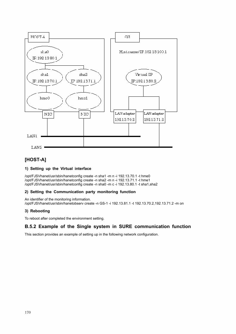
[HOST-A]
1) Setting up the Virtual interface
/opt/FJSVhanet/usr/sbin/hanetconfig create -n sha1 -m n -i 192.13.70.1 -t hme0 /opt/FJSVhanet/usr/sbin/hanetconfig create -n sha2 -m n -i 192.13.71.1 -t hme1 /opt/FJSVhanet/usr/sbin/hanetconfig create -n sha0 -m c -i 192.13.80.1 -t sha1,sha2
2) Setting the Communication party monitoring function
An identifier of the monitoring information. /opt/FJSVhanet/usr/sbin/hanetobserv create -n GS-1 -i 192.13.81.1 -t 192.13.70.2,192.13.71.2 -m on
3) Rebooting
To reboot after completed the environment setting.
B.5.2 Example of the Single system in SURE communication function
This section provides an example of setting up in the following network configuration.
170

[HOST-A]
1) Setting up the Virtual interface
/opt/FJSVhanet/usr/sbin/hanetconfig create -n sha1 -m n -i 192.13.70.1 -t hme0 /opt/FJSVhanet/usr/sbin/hanetconfig create -n sha2 -m n -i 192.13.71.1 -t hme1 /opt/FJSVhanet/usr/sbin/hanetconfig create -n sha0 -m c -i 192.13.80.1 -t sha1,sha2
2) Setting the Communication party monitoring function
/opt/FJSVhanet/usr/sbin/hanetobserv create -n 192.13.100.1 -i 192.13.80.2 -t 192.13.70.2,192.13.71.2,192.13.71.3 -m on /opt/FJSVhanet/usr/sbin/hanetobserv create -n 192.13.100.1 -i 192.13.80.2 -t 192.13.70.3,192.13.71.4,192.13.71.5 -m on
3) Rebooting
To reboot after completed the environment setting.
B.5.3 Example of the Single system in GS/SURE communication function
An example of the environment setting in a network configuration when the other system is a Hot standby system. The following configuration does not exist in SURE.
171
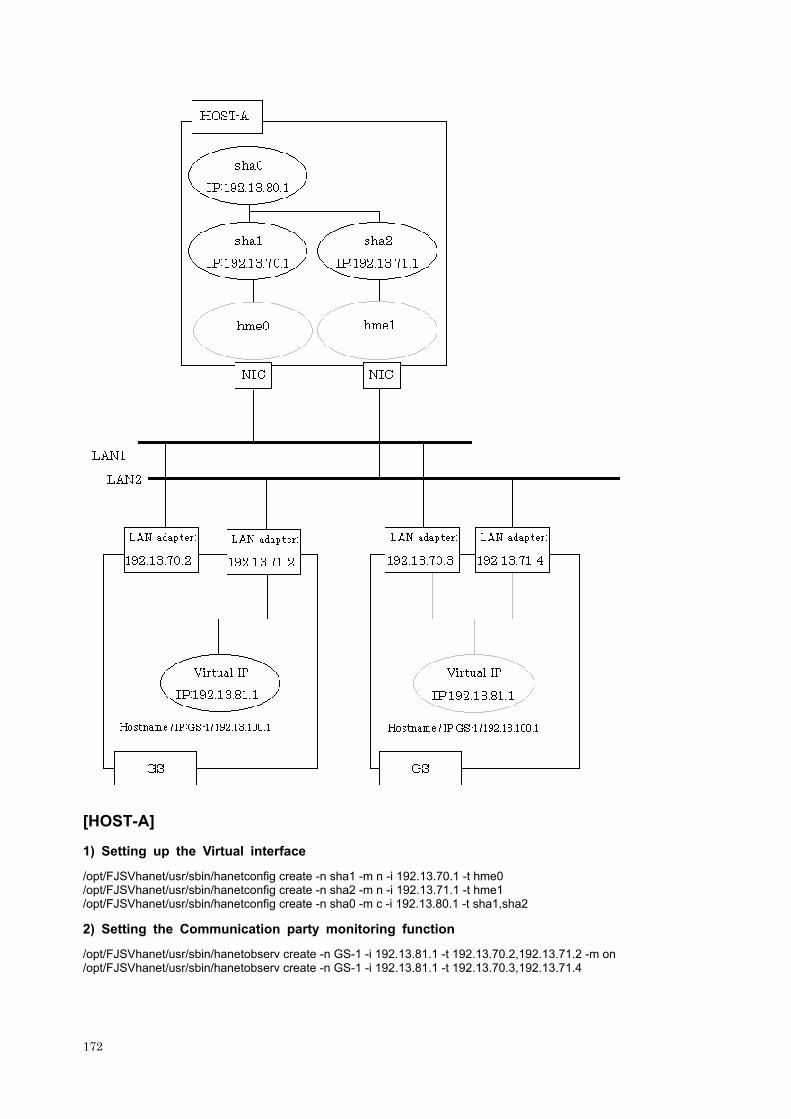
[HOST-A]
1) Setting up the Virtual interface
/opt/FJSVhanet/usr/sbin/hanetconfig create -n sha1 -m n -i 192.13.70.1 -t hme0 /opt/FJSVhanet/usr/sbin/hanetconfig create -n sha2 -m n -i 192.13.71.1 -t hme1 /opt/FJSVhanet/usr/sbin/hanetconfig create -n sha0 -m c -i 192.13.80.1 -t sha1,sha2
2) Setting the Communication party monitoring function
/opt/FJSVhanet/usr/sbin/hanetobserv create -n GS-1 -i 192.13.81.1 -t 192.13.70.2,192.13.71.2 -m on /opt/FJSVhanet/usr/sbin/hanetobserv create -n GS-1 -i 192.13.81.1 -t 192.13.70.3,192.13.71.4
172

3) Rebooting
To reboot after completed the environment setting.
B.5.4 Example of the Single system in TCP relay function
This section provides an example of setting up in the following network configuration.
173

[HOST-A]
1) Setting up the Virtual interface
/opt/FJSVhanet/usr/sbin/hanetconfig create -n sha1 -m n -i 192.13.70.1 -t hme0
174

/opt/FJSVhanet/usr/sbin/hanetconfig create -n sha2 -m n -i 192.13.71.1 -t hme1 /opt/FJSVhanet/usr/sbin/hanetconfig create -n sha0 -m c -i 192.13.80.1 -t sha1,sha2
2) Setting the Communication party monitoring function
/opt/FJSVhanet/usr/sbin/hanetobserv create -n SURE-1 -i 192.13.81.1 -t 192.13.70.2:1,192.13.71.2:1 -m on /opt/FJSVhanet/usr/sbin/hanetobserv create -n SURE-1 -i 192.13.81.2 -t 192.13.70.3:2,192.13.71.3:2 -m on
3) Setting the relay destination information
/opt/FJSVhanet/usr/sbin/hanetobserv create -i 192.13.81.1 -c 192.13.72.1,192.13.73.0:255.255.255.0
4) Rebooting
To reboot after completed the environment setting.
B.5.5 Example of the Cluster system in GS/SURE communication function
This section provides an example of setting up in the following network configuration. See such as a Cluster system manual as to the initial setting of a Cluster system and configure it. Omitted a description of a private LAN.
To make the time of all nodes synchronize before setting a Cluster system. If the time is not synchronized, occasionally it is not possible to communicate normally.
175

[HOST-A]
1) Setting up the Virtual interface
/opt/FJSVhanet/usr/sbin/hanetconfig create -n sha1-m n -i 192.13.70.1 -t hme0 /opt/FJSVhanet/usr/sbin/hanetconfig create -n sha2 -m n -i 192.13.71.1 -t hme1 /opt/FJSVhanet/usr/sbin/hanetconfig create -n sha0 -m c -i 192.13.80.1 -t sha1,sha2
176

2) Setting the Monitoring information
Setting the Communication party monitoring function
- The following is for when the other end of communication is GS (Global Server). /opt/FJSVhanet/usr/sbin/hanetobserv create -n GS-SURE -i 192.13.90.2 -t 192.13.70.3,192.13.71.3 -m on
- To specify a PM group ID that a Virtual IP address belongs to when the other end of communication is SURE. /opt/FJSVhanet/usr/sbin/hanetobserv create -n GS-SURE -i 192.13.90.2 -t 192.13.70.3:1,192.13.71.3:1 -m on
Setting the Standby node monitoring
/opt/FJSVhanet/usr/sbin/hanetobserv create -n HOST-B -i 192.13.80.10 -t 192.13.70.2,192.13.71.2 -m on
* Be sure to specify a takeover IP address for "-i" option.
3) Setting up the Cluster configuration
3-1) Registering resource
To register the resources to a Cluster system. /opt/FJSVhanet/sys/claddhanetrsc -n sha0
3-2) Setting up the takeover IP address
To execute after completed "3-1) Registering resource" in HOST-B. /opt/FJSVhanet/sys/claddhanetiprsc -n sha0 -i 192.13.80.10
3-3) Registering Cluster service
To register a service from a Cluster Management View.
3-4) Setting up the Cluster service
/opt/FJSVhanet/sys/claddhanetsvc -n sha0
4) Rebooting
When setting up of the HOST-A and HOST-B is complete, reboot both nodes simultaneously.
[HOST-B]
1) Setting up the Virtual interface
/opt/FJSVhanet/usr/sbin/hanetconfig create -n sha1 -m n -i 192.13.70.2 -t hme0 /opt/FJSVhanet/usr/sbin/hanetconfig create -n sha2 -m n -i 192.13.71.2 -t hme1 /opt/FJSVhanet/usr/sbin/hanetconfig create -n sha0 -m c -i 192.13.80.2 -t sha1,sha2
2) Setting the Monitoring information
Setting the Communication party monitoring function
- The following is for when the other end of communication is GS (Global Server). /opt/FJSVhanet/usr/sbin/hanetobserv create -n GS-SURE -i 192.13.90.2 -t 192.13.70.3,192.13.71.3 -m on
- To specify a PM group ID that a Virtual IP address belongs to when the other end of communication is SURE. /opt/FJSVhanet/usr/sbin/hanetobserv create -n GS-SURE -i 192.13.90.2 -t 192.13.70.3:1,192.13.71.3:1 -m on
Setting the Active node monitoring
/opt/FJSVhanet/usr/sbin/hanetobserv create -n HOST-A -i 192.13.80.10 -t 192.13.70.1,192.13.71.1 -m on * Be sure to specify a takeover IP address for "-i" option.
3) Setting up the Cluster configuration
3-1) Registering resource
To register the resources to a Cluster system. /opt/FJSVhanet/sys/claddhanetrsc -n sha0
177

178
4) Rebooting
When setting up of the HOST-A and HOST-B is complete, reboot both nodes simultaneously.

Appendix C Changes from old versions
C.1 Changes from Version 1.0 to Version 1.1
C.1.1 List of New Commands
SynfinityLink 1.1 supports the following new commands.
For details, see Chapter 7, "Command References".
Command name Function overview
strhanet Activating virtual interface
stphanet Inactivating virtual interface
dsphanet Displaying virtual interface status
hanetconfig print *1 Displaying Configuration Information
hanetconfig modify *1 Changing Configuration Information
hanetconfig delete *1 Deleting Configuration Information
hanetpoll Setting, Changing, Displaying, Deleting, Enabling and Disabling Router/HUB monitoring function
hanetbackup Backing up Configuration Files
hanetrestore Restoring Configuration Files *2
*1: The "hanetconfig" command is also provided by SynfinityLink 1.0
*2: Not possible to restore an environment definition file that was saved in SynfinityLink 1.0.
C.1.2 List of Incompatible Commands
SynfinityLink 1.1 does not provide the following commands:
Function outline Command name Another expedient
/opt/FJSVhanet/usr/sbin/hanetconfig start Starting SynfinityLink
(Redundant Line Control Function) /etc/rd2.d/S32hanet start
SynfinityLink is automatically activated when activated a machine. To activate a virtual interface, execute strhanet command.
/opt/FJSVhanet/usr/sbin/hanetconfig stop
Stopping SynfinityLink (Redundant Line Control Function) /etc/rc2.d/S32hanet stop
SynfinityLink stops when stopped a machine. To deactivate a virtual interface, execute stphanet command.
Command to register a procedure of the state change at the cluster operation.
/opt/FJSVhanet/usr/sys/claddhanetprc This command is automatically executed when added or deleted a cluster environment.
Command to delete a procedure of the state change at the cluster operation.
/opt/FJSVhanet/usr/sys/cldelhanetprc This command is automatically executed when added or deleted a cluster environment.
C.1.3 Other
In SynfinityLink 1.1, the command options are a bit different from those of the previous version (SynfinityLink 1.0). When setting up configuration, see Chapter 7, "Command References", for details about the command to be used.
SynfinityLink 1.1 can communicate with SynfinityLink 1.0
179

C.2 Changes from Version 1.1 to Version 2.0 / 2.1
C.2.1 List of New Commands
SynfinityLink 2.0 / 2.1 supports the following new commands.
For details, see Chapter 7, "Command References".
Command name Function overview
hanetnic Dynamic addition/deletion/switching of real interface
hanetobserv Setting communication party monitoring function
dsppoll Displaying the monitoring status
hanetparam print (*1) Displaying a list of monitoring function
*1: The "hanetparam" command is also provided by SynfinityLink 1.1
C.2.2 List of Incompatible Commands
SynfinityLink 2.0 / 2.1 does not provide the following commands:
Function outline Command name Another expedient
Setting default operation mode /opt/FJSVhanet/usr/sbin/hanetcntl
Specify for each virtual interface when you create configuration information.(hanetconfig)
For details, see Section 7.1, "hanetconfig Command".
C.2.3 Other
In SynfinityLink 2.0 / 2.1, the command options are a bit different from those of the previous version (SynfinityLink 1.1). When setting up configuration, see Chapter 7, "Command References", for details about the command to be used.
SynfinityLink 2.0 / 2.1 can communicate with SynfinityLink 1.0 and SynfinityLink 1.1.
C.3 Changes from Version 2.0 / 2.1 to Version 2.2
C.3.1 List of New Commands
SynfinityLink 2.2 supports the following new commands.
For details, see Chapter 7, "Command References".
Command name Function overview
strptl Starting Standby Patrol
stpptl Stopping Standby Patrol
C.3.2 List of Incompatible Commands
A new way of setting up by following commands is provided on SynfinityLink 2.2.
Function outline Command name Another expedient
Setting takeover IP address resource /opt/FJSVhanet/sys/claddhanetiprsc For details, see Section 7.15,
"claddhanetiprsc Command".
Registering service resource of the takeover IP address resource /opt/FJSVhanet/sys/claddhanetsvc For details, see Section 7.16,
"claddhanetsvc Command".
Deleting virtual interface resource /opt/FJSVhanet/sys/cldelhanetrsc For details, see Section 7.17, "cldelhanetrsc Command".
Deleting takeover IP address resource /opt/FJSVhanet/sys/cldelhanetiprsc For details, see Section 7.18,
"cldelhanetiprsc Command".
Deleting service resource of the takeover IP address resource /opt/FJSVhanet/sys/cldelhanetsvc For details, see Section 7.19,
"cldelhanetsvc Command".
180

C.3.3 Other
In SynfinityLink 2.2, when communicate with SynfinityLink 2.0 / 2.1, SynfinityLink 1.1, and SynfinityLink 1.0, necessary to apply a patch to SynfinityLink 2.0 / 2.1, SynfinityLink 1.1, and SynfinityLink 1.0. See "INSTALLATION GUIDE SynfinityLink 2.2" for the detail.
181

182

Appendix D Others
D.1 Commands for Registering and Deleting Cluster Resources
A new way of setting up a cluster resource is provided on SynfinityLink 2.2 for the purpose of simplification. However, you can also register or delete a cluster resource in a way used on SynfinityLink 2.1 or earlier. The following describes registering and deleting a cluster resource by acquiring a resource ID using the clgettree command provided by the cluster system.
For normal setup purposes, you are recommended to register or delete a cluster resource in the way described in Chapter 7, "Command References".
D.1.1 claddhanetrsc command
The way of specifying this command is not changed. For information, see Section 7.14, "claddhanetrsc Command".
D.1.2 claddhanetiprsc command
For information on the feature of this command, see Section 7.15, "claddhanetiprsc Command".
[Synopsis]
/opt/FJSVhanet/sys/claddhanetiprsc -p gp_rid1,gp_rid2 -i ip_address [-k key]
[Option]
You can specify the following options:
-p gp_rid1, gp_rid2
Specify the resource ID of a virtual interface on which a takeover IP address should be set. In gp_rid1, specify the resource ID of a virtual interface on the active node. In gp_rid2, specify the resource ID of a virtual interface on the standby node. For information on acquiring resource IDs to be specified, see Section D.2.1, "Acquiring HAnet class resource".
-i ip_address
Specify a takeover IP address.
In ip_address, specify an IP address or host name to be taken over. In NIC switching mode (operation mode "d" or "e"), no takeover IP address need to be specified for a virtual interface.
-k key
Specify the resource key of a shared resource to be registered. The resource key specified in this option is used as the resource name. This option may be omitted. If this option is omitted, the takeover IP address specified in the -i option is used as the resource key. As the resource key, you can specify only ASCII uppercase and lowercase alphabetic characters, numeric characters, hyphens ("-"), underlines ("_"), periods ("."), slashes ("/"), and colons (":"). The resource key must start with either an ASCII uppercase or lowercase alphabetic character or a numeric character.
D.1.3 claddhanetsvc command
For information on the feature of this command, see Section 7.16, "claddhanetsvc Command".
[Name]
claddhanetsvc - Setting a takeover IP address to the service
[Synopsis]
/opt/FJSVhanet/sys/claddhanetsvc -s src_rid1,src_rid2 -d dst_rid1,dst_rid2
[Option]
You can specify the following options:
183

-s src_rid1, src_rid2
Specify the resource ID of a takeover IP address resource to be registered in the service tree. In src_rid1, specify the resource ID of a takeover IP address resource on the active node. In src_rid2, specify the resource ID of a takeover IP address resource on the standby node. For information on acquiring resource IDs to be specified, see Section D.2.2, "Acquiring HAnet_IPaddresss class resource".
-d dst_rid1, dst_rid2
Specify the resource ID of a service instance to which a takeover IP address resource should be registered. In dst_rid1, specify the resource ID for an active instance. In dst_rid2, specify the resource ID for a standby instance. For information on acquiring resource IDs to be specified, see Section D.2.3, "Acquiring service instance resources".
D.1.4 cldelhanetrsc command
For information on the feature of this command, see Section 7.17, "cldelhanetrsc Command".
[Name]
cldelhanetrsc - Deleting the resource of a virtual interface
[Synopsis]
/opt/FJSVhanet/sys/cldelhanetrsc -r resource-id
[Option]
You can specify the following option:
-r resource-id
Specify the resource ID of a virtual interface to be deleted.
In resource-id, specify a resource ID on the node on which this command should be executed. For information on acquiring a resource ID to be specified, see Section D.2.1, "Acquiring HAnet class resource".
D.1.5 cldelhanetiprsc command
For information on the feature of this command, see Section 7.18, "cldelhanetiprsc Command".
[Name]
cldelhanetiprsc - Deleting the resource of a takeover IP address
[Synopsis]
/opt/FJSVhanet/sys/cldelhanetiprsc -n resource-name
[Feature description]
The cldelhanetiprsc command deletes the resource information of a takeover IP address from the resource database held by the cluster control.
[Option]
You can specify the following option:
-r resource-name
Specify the resource name of a takeover IP address to be deleted.
If the resource key name is specified as an arbitrary character string in the "-k" option when it is created (claddhanetiprsc), specify the character string. If the "-k" option is not specified, specify the takeover IP address (or host name).
D.1.6 cldelhanetsvc command
For information on the feature of this command, see Section 7.19, "cldelhanetsvc Command".
[Name]
cldelhanetsvc - Deleting a takeover IP address from the service
184
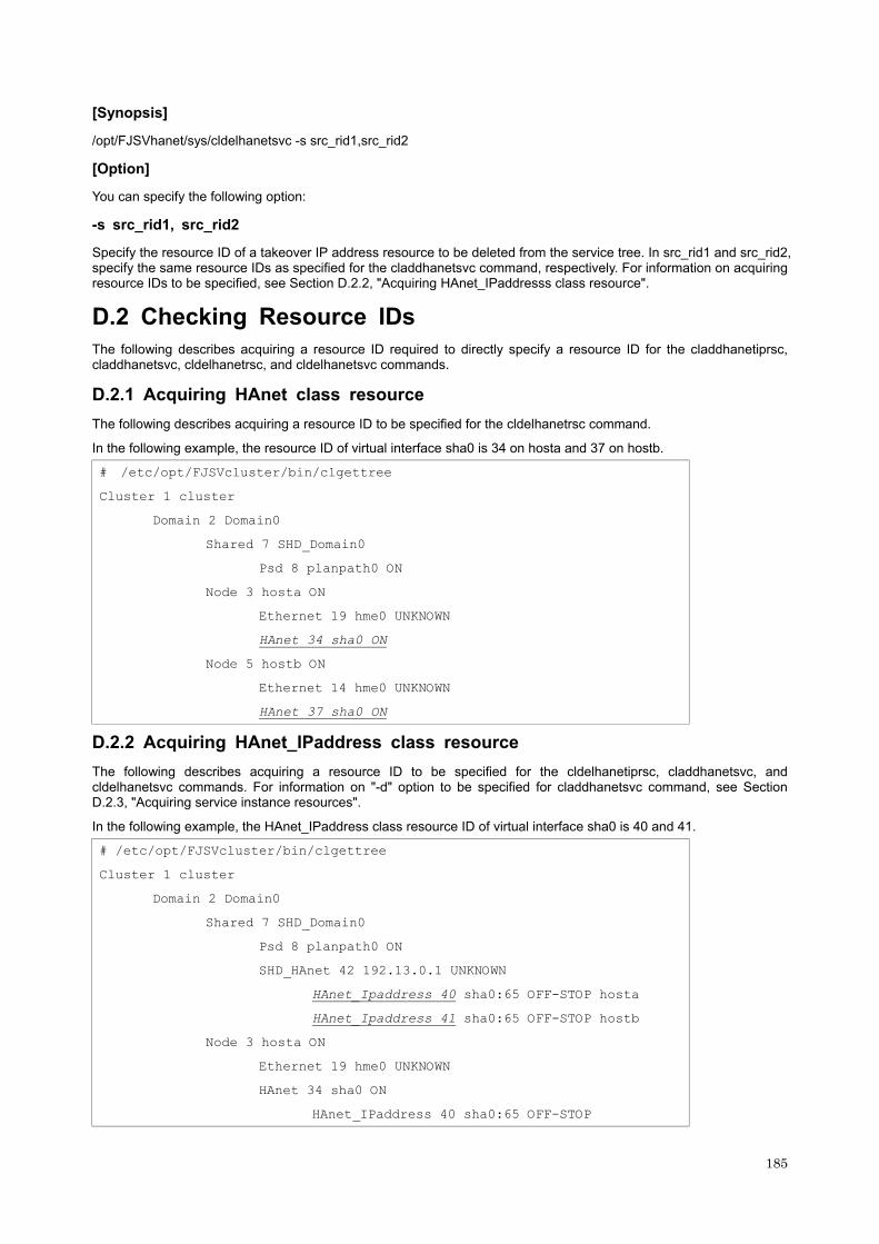
[Synopsis]
/opt/FJSVhanet/sys/cldelhanetsvc -s src_rid1,src_rid2
[Option]
You can specify the following option:
-s src_rid1, src_rid2
Specify the resource ID of a takeover IP address resource to be deleted from the service tree. In src_rid1 and src_rid2, specify the same resource IDs as specified for the claddhanetsvc command, respectively. For information on acquiring resource IDs to be specified, see Section D.2.2, "Acquiring HAnet_IPaddresss class resource".
D.2 Checking Resource IDs
The following describes acquiring a resource ID required to directly specify a resource ID for the claddhanetiprsc, claddhanetsvc, cldelhanetrsc, and cldelhanetsvc commands.
D.2.1 Acquiring HAnet class resource
The following describes acquiring a resource ID to be specified for the cldelhanetrsc command.
In the following example, the resource ID of virtual interface sha0 is 34 on hosta and 37 on hostb.
# /etc/opt/FJSVcluster/bin/clgettree
Cluster 1 cluster
Domain 2 Domain0
Shared 7 SHD_Domain0
Psd 8 planpath0 ON
Node 3 hosta ON
Ethernet 19 hme0 UNKNOWN
HAnet 34 sha0 ON
Node 5 hostb ON
Ethernet 14 hme0 UNKNOWN
HAnet 37 sha0 ON
D.2.2 Acquiring HAnet_IPaddress class resource
The following describes acquiring a resource ID to be specified for the cldelhanetiprsc, claddhanetsvc, and cldelhanetsvc commands. For information on "-d" option to be specified for claddhanetsvc command, see Section D.2.3, "Acquiring service instance resources".
In the following example, the HAnet_IPaddress class resource ID of virtual interface sha0 is 40 and 41.
# /etc/opt/FJSVcluster/bin/clgettree
Cluster 1 cluster
Domain 2 Domain0
Shared 7 SHD_Domain0
Psd 8 planpath0 ON
SHD_HAnet 42 192.13.0.1 UNKNOWN
HAnet_Ipaddress 40 sha0:65 OFF-STOP hosta
HAnet_Ipaddress 41 sha0:65 OFF-STOP hostb
Node 3 hosta ON
Ethernet 19 hme0 UNKNOWN
HAnet 34 sha0 ON
HAnet_IPaddress 40 sha0:65 OFF-STOP
185
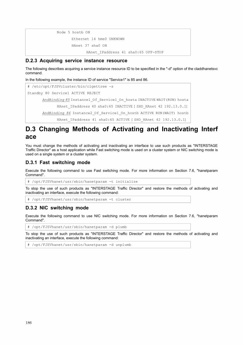
186
Node 5 hostb ON
Ethernet 14 hme0 UNKNOWN
HAnet 37 sha0 ON
HAnet_IPaddress 41 sha0:65 OFF-STOP
D.2.3 Acquiring service instance resource
The following describes acquiring a service instance resource ID to be specified in the "-d" option of the claddhanetsvc command.
In the following example, the instance ID of service "Service1" is 85 and 86.
# /etc/opt/FJSVcluster/bin/clgettree -s
Standby 80 Service1 ACTIVE REJECT
AndBinding 85 Instance1_Of_Service1_On_hosta INACTIVE WAIT(RUN) hosta
HAnet_IPaddress 40 sha0:65 INACTIVE [SHD_HAnet 42 192.13.0.1]
AndBinding 86 Instance2_Of_Service1_On_hostb ACTIVE RUN(WAIT) hostb
HAnet_IPaddress 41 sha0:65 ACTIVE [SHD_HAnet 42 192.13.0.1]
D.3 Changing Methods of Activating and Inactivating Interface
You must change the methods of activating and inactivating an interface to use such products as "INTERSTAGE Traffic Director" as a host application while Fast switching mode is used on a cluster system or NIC switching mode is used on a single system or a cluster system.
D.3.1 Fast switching mode
Execute the following command to use Fast switching mode. For more information on Section 7.6, "hanetparam Command".
# /opt/FJSVhanet/usr/sbin/hanetparam -t initialize
To stop the use of such products as "INTERSTAGE Traffic Director" and restore the methods of activating and inactivating an interface, execute the following command:
# /opt/FJSVhanet/usr/sbin/hanetparam -t cluster
D.3.2 NIC switching mode
Execute the following command to use NIC switching mode. For more information on Section 7.6, "hanetparam Command".
# /opt/FJSVhanet/usr/sbin/hanetparam -d plumb
To stop the use of such products as "INTERSTAGE Traffic Director" and restore the methods of activating and inactivating an interface, execute the following command:
# /opt/FJSVhanet/usr/sbin/hanetparam -d unplumb