Synergy Project
17
ID Task Mode Task Name Duration Start Finish 1 2 Signing of Supply agreement 1 day Sat 3/26/16 Sat 3/26/16 3 Site visit to Synergy 1 day Mon 4/4/16 Mon 4/4/16 4 Provide foundation compliance 1 day Mon 4/4/16 Mon 4/4/16 5 Finalize Equipment GA - inspection on replacement requirement 2 days Tue 4/5/16 Wed 4/6/16 6 BOM List 1 day Thu 4/7/16 Thu 4/7/16 7 8 Material Procurement 45 days Fri 4/8/16 Thu 6/9/16 9 internal Ambient Vaporizer 45 days Mon 4/4/16 Fri 6/3/16 10 Valves and Regulators replacement 45 days Mon 4/4/16 Fri 6/3/16 11 To find out on transfering of JKKP file, PMT 235, Ownership and original drawing or document. 50 days Tue 4/5/16 Mon 6/13/16 12 Get Qoute on cranage, skylift & low loader once finalise the delivery date 7 days Tue 5/3/16 Wed 5/11/16 13 Appoint cranage, skylift & low loader (Bkt Minyak) 2 days Wed 6/1/16 Thu 6/2/16 14 Appoint cranage and skylift(Kajang) 2 days Wed 6/1/16 Thu 6/2/16 15 16 SYNERGY Site work 17 Pre-Fabrication Work civil and roof structural ( by Synergy) 45 days Mon 4/4/16 Fri 6/3/16 18 Plinth Construction & curing 15 days Fri 5/13/16 Thu 6/2/16 19 Fencing and Gate fabrication Mon 4/4/16 20 Qoute for stirage cleaning, touich up, install PBU system 3 days Mon 4/25/16 Wed 4/27/16 21 Cleaning of storage tank & touch up 3 days Mon 6/6/16 Wed 6/8/16 22 Install Internal Pressure build up system 3 days Mon 6/6/16 Wed 6/8/16 23 KOM (Kick Off Meeting at site) 1 day Tue 6/21/16 Tue 6/21/16 24 Cranage - lifting tank SIG Bkt Minyak site 1 day Wed 6/22/16 Wed 6/22/16 25 Storage tank transportation 1 day Wed 6/22/16 Wed 6/22/16 26 Final Work - Position of VIE 1 day Thu 6/23/16 Thu 6/23/16 27 Arrival of Storage tank 1 day Thu 6/23/16 Thu 6/23/16 28 Cranage - lifting tank Synergy site 1 day Thu 6/23/16 Thu 6/23/16 29 Purging of Storage Tank, Vacuum reading 2 days Thu 6/23/16 Fri 6/24/16 30 Transfill Liquid into Storage tank 1 day Thu 6/23/16 Thu 6/23/16 31 Analysis on Storage tank 1 day Thu 6/23/16 Thu 6/23/16 32 ORI 1 day Thu 6/23/16 Thu 6/23/16 33 System Test & Commissioning 1 day Thu 6/23/16 Thu 6/23/16 34 Training to customer 1 day Fri 6/24/16 Fri 6/24/16 35 Hand Over 1 day Fri 6/24/16 Fri 6/24/16 T F S S M T W T F S S M T W T F S S M T W T F S S M T W T F S S M T W T F S S M T W T F S S M T W T F S S M T W T F S S M T W T F S S M T W T F S S M T W T F S S M T W T F S S M T W T F S S Mar 27, '16 Apr 3, '16 Apr 10, '16 Apr 17, '16 Apr 24, '16 May 1, '16 May 8, '16 May 15, '16 May 22, '16 May 29, '16 Jun 5, '16 Jun 12, '16 Jun 19, '16 Ju Task Split Milestone Summary Project Summary External Tasks External Milestone Inactive Task Inactive Milestone Inactive Summary Manual Task Duration-only Manual Summary Rollup Manual Summary Start-only Finish-only Deadline Progress Page 1 Synergy Gas & Welding CO2 tank
-
Upload
adrian-mah-siew-hoe -
Category
Documents
-
view
27 -
download
1
Transcript of Synergy Project

ID Task Mode
Task Name Duration Start Finish
1
2 Signing of Supply agreement 1 day Sat 3/26/16 Sat 3/26/16
3 Site visit to Synergy 1 day Mon 4/4/16 Mon 4/4/16
4 Provide foundation compliance 1 day Mon 4/4/16 Mon 4/4/16
5 Finalize Equipment GA - inspection on replacement requirement
2 days Tue 4/5/16 Wed 4/6/16
6 BOM List 1 day Thu 4/7/16 Thu 4/7/16
7
8 Material Procurement 45 days Fri 4/8/16 Thu 6/9/16
9 internal Ambient Vaporizer 45 days Mon 4/4/16 Fri 6/3/16
10 Valves and Regulators replacement 45 days Mon 4/4/16 Fri 6/3/16
11 To find out on transfering of JKKP file, PMT 235, Ownership and original drawing or document.
50 days Tue 4/5/16 Mon 6/13/16
12 Get Qoute on cranage, skylift & low loader once finalise the delivery date
7 days Tue 5/3/16 Wed 5/11/16
13 Appoint cranage, skylift & low loader (Bkt Minyak)
2 days Wed 6/1/16 Thu 6/2/16
14 Appoint cranage and skylift(Kajang) 2 days Wed 6/1/16 Thu 6/2/16
15
16 SYNERGY Site work
17 Pre-Fabrication Work civil and roof structural (by Synergy)
45 days Mon 4/4/16 Fri 6/3/16
18 Plinth Construction & curing 15 days Fri 5/13/16 Thu 6/2/16
19 Fencing and Gate fabrication Mon 4/4/16
20 Qoute for stirage cleaning, touich up, install PBU system
3 days Mon 4/25/16 Wed 4/27/16
21 Cleaning of storage tank & touch up 3 days Mon 6/6/16 Wed 6/8/16
22 Install Internal Pressure build up system 3 days Mon 6/6/16 Wed 6/8/16
23 KOM (Kick Off Meeting at site) 1 day Tue 6/21/16 Tue 6/21/16
24 Cranage - lifting tank SIG Bkt Minyak site 1 day Wed 6/22/16 Wed 6/22/16
25 Storage tank transportation 1 day Wed 6/22/16 Wed 6/22/16
26 Final Work - Position of VIE 1 day Thu 6/23/16 Thu 6/23/16
27 Arrival of Storage tank 1 day Thu 6/23/16 Thu 6/23/16
28 Cranage - lifting tank Synergy site 1 day Thu 6/23/16 Thu 6/23/16
29 Purging of Storage Tank, Vacuum reading 2 days Thu 6/23/16 Fri 6/24/16
30 Transfill Liquid into Storage tank 1 day Thu 6/23/16 Thu 6/23/16
31 Analysis on Storage tank 1 day Thu 6/23/16 Thu 6/23/16
32 ORI 1 day Thu 6/23/16 Thu 6/23/16
33 System Test & Commissioning 1 day Thu 6/23/16 Thu 6/23/16
34 Training to customer 1 day Fri 6/24/16 Fri 6/24/16
35 Hand Over 1 day Fri 6/24/16 Fri 6/24/16
T F S S M T W T F S S M T W T F S S M T W T F S S M T W T F S S M T W T F S S M T W T F S S M T W T F S S M T W T F S S M T W T F S S M T W T F S S M T W T F S S M T W T F S S M T W T F S SMar 27, '16 Apr 3, '16 Apr 10, '16 Apr 17, '16 Apr 24, '16 May 1, '16 May 8, '16 May 15, '16 May 22, '16 May 29, '16 Jun 5, '16 Jun 12, '16 Jun 19, '16 Jun 26, '16
Task
Split
Milestone
Summary
Project Summary
External Tasks
External Milestone
Inactive Task
Inactive Milestone
Inactive Summary
Manual Task
Duration-only
Manual Summary Rollup
Manual Summary
Start-only
Finish-only
Deadline
Progress
Page 1
Synergy Gas & Welding CO2 tank

Synergy Project
Phase 1: Moving of VIE tank from SIG Penang to Synergy
Date of commencement: 22nd June 2016 (Wednesday)
Agenda:
- Monitor the condition of the CO2 storage tank
- Ensure the pressure inside tank is more than 5 bar (prevent dry ice formation)
- Ensure no liquid CO2 inside the tank
- To test the safety relief valve and ensure that both are in correct set pressure (350 psi or 24
bar)
- To test the Differential Pressure Gauge (DP Gauge or Liquid Level Gauge) and ensure it’s in
the within the tolerance errors ( Instrument Used – CPP 30 Test Pump, Pneumatic Wikai )
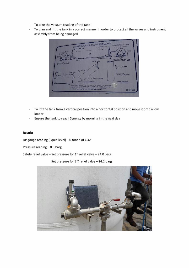
- To take the vacuum reading of the tank
- To plan and lift the tank in a correct manner in order to protect all the valves and instrument
assembly from being damaged
- To lift the tank from a vertical position into a horizontal position and move it onto a low
loader
- Ensure the tank to reach Synergy by morning in the next day
Result:
DP gauge reading (liquid level) – 0 tonne of CO2
Pressure reading – 8.5 barg
Safety relief valve – Set pressure for 1st relief valve – 24.0 barg
Set pressure for 2nd relief valve – 24.2 barg

Vacuum reading – 0.126 torr or 0.01934 psi
DP gauge testing –
Instrument reading
Actual Reading Percentage Error
mBar tonne of CO2 tonne of CO2 %
90.6 2.182 1.80 17.51 %
181.2 4.364 3.78 13.38 %
271.8 6.546 5.75 12.16 %
362.4 8.728 7.75 11.21 %
453 10.910 9.75 10.63 %
543.6 13.092 11.80 9.87 %
634.2 15.274 13.8 9.65 %
724.8 17.456 15.8 9.49 %
815.4 19.638 17.8 9.36 %
906 21.820 19.8 9.26 %
Status – Completed on 15th June 2016 and the overall condition of the tank is fine

Phase 2: Positioning of VIE tank onto fabricated support
Date of commencement: 23rd June 2016 (Thursday)
Agenda:
- To position the VIE tank from horizontal position into a vertical positon
- To move the VIE tank onto the fabricated support with a proper alignment
- To wall plug the VIE tank onto the platform as a mean indication of finalizing the position of
the VIE tank

Result:
Status: Completed on 23rd June 2016

Phase 3: Welding and to connect the PBC (Pressure Building Coil) onto the tank
Date of commencement: 24 to 25th June 2016 (Friday to Saturday)
Agenda:
- To fabricate two square flange with gasket for the PBC unit
- To weld a 1” schedule 40 pipe to both of the square flanges
- To thread 1” NPT pipe connection for the Pressure Build-up Regulator (2 of them in total)
- To weld the remaining socket weld ball valve to connect the PBC from V7 to V13
- To build sufficient base support to withstand the weight of both the PBC and regulator
Result:
Status: Completed on 25th June 2016
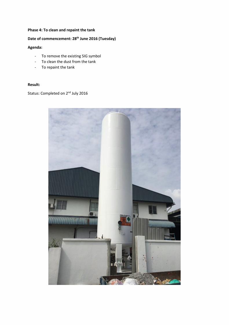
Phase 4: To clean and repaint the tank
Date of commencement: 28th June 2016 (Tuesday)
Agenda:
- To remove the existing SIG symbol
- To clean the dust from the tank
- To repaint the tank
Result:
Status: Completed on 2nd July 2016

Phase 5: To fill liquid carbon dioxide (20 tonnes) into the VIE tank
Date of commencement: 29th June 2016 (Friday)
Agenda:
- To fill 20 tonnes of LCO into the VIE tank (by Cyromaster and monitored by Gopa)
- To analyze the carbon dioxide purity after liquid filling (by QA Nilai, Mr Lai)
- To train Synergy personnel onto the refilling process and pressure building coil (by Gopa)
Result:
Liquid level after filling – 17 tonnes of CO2
VIE Pressure – 19 bar
Gas purity analysis – 99.6 to 99.7 %

Refilling training by Gopa to Synergy personnel – Done, however need more training onto the
technical stuff
Status: Completed on 29th July 2016


SYNERGY GAS & WELDING SDN. BHD.
Document No.
WORK INSTRUCTION
Title: Carbon Dioxide Refilling
Rev. No.
00
Page
1 of 3
Approved By
1.0 Purpose
To define the procedure for refilling liquid for carbon dioxide cylinder.
2.0 Scope
This procedure applies to production supervisor & operators for standard
procedure of baking out moisture from cylinders.
3.0 Definition
Nil
4.0 Related Documents
Appendix 1 Carbon Dioxide Refilling Station (P&ID)
5.0 Procedure (For refilling carbon dioxide cylinder)
Pre-operation
5.1 Ensure that the pressure within the storage tank at 15 bar and above (18 bar to
20 barg would be the best). If the pressure is lower than 15 bar, then operator
can use the Pressure Building Coil (PBC) to increase the tank pressure to 19
bar (refer to Section 6.0).
5.2 Ensure that the P1100 is filled with oil (where the sight glass is full can be
seen).
5.3 Ensure that all valves within the refilling station has been closed or shut.
Operation
It is important to cool down the pump before starting it and appropriate pressurization
procedures should be followed to ensure that no dry ice formation (solid carbon
dioxide).
5.3 First, open the pump return valve (V-4) as shown in the appendix figure to
allow pressurization of the line to be taken place. Then, open switch the 3-way
valve (V-3) where the flow can be directed from pump to storage tank.
5.4 After the pressurization process, open the liquid supply line (V-1) to begin the
cooling process. The cooling process will take around 10 to 15 minutes,
however, the process itself can be accelerated by opening the vent/cooling
valve (V-2) until liquid phase can be seen flowing out and the pump cylinder
is icing. When the cooling is sufficient, close the vent valve (V-2) and start the

SYNERGY GAS & WELDING SDN. BHD.
Document No.
WORK INSTRUCTION
Title: Carbon Dioxide Refilling
Rev. No.
00
Page
2 of 3
Approved By
pump. (* Make sure that the 3-way valve is flowing from the pump to the
storage tank to prevent overpressure).
5.5 With the pump is running, place both gas cylinders onto the weighing
machines. Then, connect the flex hoses to both of the cylinders and open the
cylinder head valve on both. (* Always remember and ensure that the cylinder
valve is opened to prevent over-pressure within the line which can be
dangerous.)
5.6 Then, turn the 3-way valve (V-3) to allow the flow direction coming from the
pump to the refilling line and open the line valve (V-5) to begin the filling
process. (* Make sure that the line valve at V-6 is closed.)
5.7 After the refilling process is done where the weight has reaches its appropriate
capacity, close the line valve (V-5) and open the line valve (V-6) so the other
gas cylinder can be filled. While waiting, remove the flex hose on the first gas
cylinder and remove it from the weighting machine. The new gas cylinder
then can be put onto the weighing machine waiting to be refilled, the process
can be repeated from 5.4 to continue the refilling process.
Post-operation
5.9 To shut the refilling station, first close all the line valve (V-5) and (V-6) and
turn the 3-way valve to the direction flowing from pump to storage tank.
5.10 Then only proceed to stop the pump and close both valves at (V-1) and (V-4)
to ensure no more liquid and vapour is flowing into the line. Finally, vent the
remaining liquid and gas by opening the vent valve (V-2) until the remaining
pressure dropped to zero.
6.0 Procedure (For building tank pressure)
To build the tank pressure
6.1 If the tank pressure is lower than 15 bar, operators can build the tank pressure
itself by following the procedures below. First, ensure that the valves from
Bottom Fill and Gas Balancer are closed.
6.2 Then slowly open the valve at (V-7) and wait for a few minutes, this will
allow time for the liquid to vaporize into gas with high pressure.
6.3 Open the valve at (V-8) and (V-9) to allow the high pressure gas to flow into
the tank to increase the tank pressure. This process might takes around 10
minutes and more. If the pressure increased to 18 bar, then proceed to close
valve at (V-7), (V-8) and (V-9). The operators can then proceed to refill for
the carbon dioxide cylinders.

SYNERGY GAS & WELDING SDN. BHD.
Document No.
WORK INSTRUCTION
Title: Carbon Dioxide Refilling
Rev. No.
00
Page
3 of 3
Approved By
APPENDIX 1: Carbon Dioxide Refilling Station (P&ID)

CONFIDENTIAL
THIS DRAWING IS OWNED BY SOUTHERN
INDUSTRIAL GAS SDN BHD, CONTAINS
PROPRIETY INFORMATION AND SHOULD
NOT BE DISTRIBUTED, COPIED,
REPRODUCED FOR ANY OTHER
PURPOSES WITHOUT PROPER
AUTHORIZATION.
SYNERGY GAS & WELDING
SDN BHD
15, Jalan P2/18, Seksyen 2, Bandar
Teknologi Kajang, 43500 Semenyih,
Selangor D. E.
TEL: 03-8723 6881 FAX: 03-8724 6881
DRAWING TITLE:
Appendix 1: Carbon Dioxide
Refilling Station (P&ID)
DRAWING NO.
DRAWN BY
CHECKED BY
APPROVED BY
DATE
SCALE
GENERAL NOTES/ REMARKS:
REV.
DRAWN
BY.
CHECKED
BY.
DATEREMARKS
Synergy
Bottom
Fill
Gas
Balancer
Pressure
Gauge
Differential Pressure
Gauge (in tonnes CO ₂)
CO2 Storage
Tank
(20 tonnes)
Pressure
Gauge
Burst Disc:
2000 psi
Relief Valve:
1200 psi
Relief Valve:
1000 psi
Check
Valve
Vent/ Cooling
Valve
P 1100
Pump
3-way Valve
(L shape)
Thermal
Relief Valve:
1200 psi
V-1
V-2
V-3
V-4
V-5
V-6
Normally
Open
Normally
Open
Y-strainer
Carbon Dioxide
Cylinder 1
V-7
V-8
V-9
Relief Valve:
350 psi
Pressure
Building Coil
Regulator:
275 psi
(19 barg)
Carbon Dioxide
Cylinder 2
Liquid Phase
Gas Phase
ADRIAN MAH
29/7/2016