Synergy MQTT/TLS Azure Cloud Connectivity …...AMQP 1.0. The Azure IoT protocol gateway includes an...
42
Application Note R11AN0337EU0105 Rev.1.05 Page 1 of 41 Nov.01.19 Renesas Synergy™ Platform Synergy MQTT/TLS Azure Cloud Connectivity Solution Introduction This application note describes IoT Cloud connectivity solution in general and introduces you briefly to the IoT Cloud provider Microsoft Azure. It covers the Synergy MQTT/TLS module, its features, and operational flow sequence (Initialization/Data flow). The application example provided in the package uses Azure IoT Hub. Using detailed steps, this document instructs first-time Microsoft Azure users how to configure the Azure IoT Hub platform to run this application example demonstration. This application note enables you to effectively use the Synergy MQTT/TLS modules in your own design. Upon completion of this guide, you will be able to add the MQTT/TLS module to your own design, configure it correctly for the target application, and write code using the included application example code as a reference and efficient starting point. References to more detailed API descriptions, and other application projects that demonstrate more advanced uses of the module, are in the Synergy Software Package (SSP) User’s Manual (see Next Steps section), and serve as valuable resources in creating more complex designs. AE-CLOUD1 and AE-CLOUD2 kits support the Synergy MQTT/TLS AWS Cloud Connectivity solution. Required Resources To build and run the MQTT/TLS application example, you need: Development tools & software • e 2 studio ISDE v7.3.0 or later or IAR Embedded Workbench ® for Renesas Synergy ™ v8.23.3 or later (www.renesas.com/synergy/tools). • Synergy Software Package (SSP) v1.6.2 or later (www.renesas.com/synergy/ssp). • Synergy Standalone Configurator (SSC) v7.3.0 or later (www.renesas.com/synergy/ssc). • SEGGER J-link ® USB driver (www.renesas.com/synergy/jlinksynergy). • When migrating to future SSP versions, follow the corresponding SSP release note to establish the required development environment. Hardware • Renesas Synergy™ AE-CLOUD1 kit (includes a Wi-Fi board (www.renesas.com/synergy/ae-cloud1); and, the AE-CLOUD2 kit (www.renesas.com/synergy/ae-cloud2), which includes a Pillar board, Wi-Fi board and BG96 Cellular shield). Note: A separate CAT-M1, NB-IoT, or EGPRS SIM card should be procured for cellular functionality. • Renesas Synergy™ Application Example kit’s PMOD-based Wi-Fi Module (www.renesas.com/synergy/ae-wifi1). • PC running Windows ® 7 or 10; Tera Term console or similar application, and an installed web browser (Google Chrome, Internet Explorer, Microsoft Edge, Mozilla Firefox, or Safari). • Micro USB cables • Ethernet cable Prerequisites and Intended Audience This application note assumes that you have some experience with the Renesas e 2 studio ISDE and Synergy Software Package (SSP). Before you perform the procedures in this application note, follow the procedure in the SSP User Manual to build and run the Blinky project. Doing so enables you to become familiar with the e 2 studio/IAR and the SSP, and also validates that the debug connection to your board functions properly. In addition, this application note assumes you have some knowledge of MQTT/TLS and its communication protocols. The intended audience are users who want to develop applications with MQTT/TLS modules using Renesas Synergy ™ S5 or S7 MCU Series.
Transcript of Synergy MQTT/TLS Azure Cloud Connectivity …...AMQP 1.0. The Azure IoT protocol gateway includes an...
Application Note
R11AN0337EU0105 Rev.1.05 Page 1 of 41 Nov.01.19
Renesas Synergy™ Platform
Synergy MQTT/TLS Azure Cloud Connectivity Solution Introduction This application note describes IoT Cloud connectivity solution in general and introduces you briefly to the IoT Cloud provider Microsoft Azure. It covers the Synergy MQTT/TLS module, its features, and operational flow sequence (Initialization/Data flow). The application example provided in the package uses Azure IoT Hub. Using detailed steps, this document instructs first-time Microsoft Azure users how to configure the Azure IoT Hub platform to run this application example demonstration.
This application note enables you to effectively use the Synergy MQTT/TLS modules in your own design. Upon completion of this guide, you will be able to add the MQTT/TLS module to your own design, configure it correctly for the target application, and write code using the included application example code as a reference and efficient starting point. References to more detailed API descriptions, and other application projects that demonstrate more advanced uses of the module, are in the Synergy Software Package (SSP) User’s Manual (see Next Steps section), and serve as valuable resources in creating more complex designs.
AE-CLOUD1 and AE-CLOUD2 kits support the Synergy MQTT/TLS AWS Cloud Connectivity solution.
Required Resources To build and run the MQTT/TLS application example, you need:
Development tools & software • e2 studio ISDE v7.3.0 or later or IAR Embedded Workbench® for Renesas Synergy™ v8.23.3 or later
(www.renesas.com/synergy/tools). • Synergy Software Package (SSP) v1.6.2 or later (www.renesas.com/synergy/ssp). • Synergy Standalone Configurator (SSC) v7.3.0 or later (www.renesas.com/synergy/ssc). • SEGGER J-link® USB driver (www.renesas.com/synergy/jlinksynergy). • When migrating to future SSP versions, follow the corresponding SSP release note to establish the
required development environment. Hardware • Renesas Synergy™ AE-CLOUD1 kit (includes a Wi-Fi board (www.renesas.com/synergy/ae-cloud1); and,
the AE-CLOUD2 kit (www.renesas.com/synergy/ae-cloud2), which includes a Pillar board, Wi-Fi board and BG96 Cellular shield). Note: A separate CAT-M1, NB-IoT, or EGPRS SIM card should be procured for cellular
functionality. • Renesas Synergy™ Application Example kit’s PMOD-based Wi-Fi Module
(www.renesas.com/synergy/ae-wifi1). • PC running Windows® 7 or 10; Tera Term console or similar application, and an installed web browser
(Google Chrome, Internet Explorer, Microsoft Edge, Mozilla Firefox, or Safari). • Micro USB cables • Ethernet cable
Prerequisites and Intended Audience This application note assumes that you have some experience with the Renesas e2 studio ISDE and Synergy Software Package (SSP). Before you perform the procedures in this application note, follow the procedure in the SSP User Manual to build and run the Blinky project. Doing so enables you to become familiar with the e2 studio/IAR and the SSP, and also validates that the debug connection to your board functions properly. In addition, this application note assumes you have some knowledge of MQTT/TLS and its communication protocols.
The intended audience are users who want to develop applications with MQTT/TLS modules using Renesas Synergy™ S5 or S7 MCU Series.
Renesas Synergy™ Platform Synergy MQTT/TLS Azure Cloud Connectivity Solution
R11AN0337EU0105 Rev.1.05 Page 2 of 41 Nov.01.19
Contents
1. Introduction to Cloud Connectivity ........................................................................................... 4 1.1 Overview .................................................................................................................................................. 4 1.2 Major Components .................................................................................................................................. 4 1.3 Cloud Provider Overview ......................................................................................................................... 5 1.3.1 Microsoft Azure IoT Solution ................................................................................................................. 5 1.3.1.1 Key Features ..................................................................................................................................... 6 1.4 MQTT Protocol Overview ........................................................................................................................ 6 1.5 TLS Protocol Overview ............................................................................................................................ 7 1.5.1 Device Certificates and Keys ................................................................................................................ 8 1.5.1.1 Device Certificates ............................................................................................................................ 8 1.5.1.2 Loading Certificates onto your Device .............................................................................................. 8 1.5.1.3 Generating Self-Signed Certificates .................................................................................................. 8 1.5.2 Device Security Recommendations ...................................................................................................... 9
2. Synergy MQTT/TLS Cloud Solution ......................................................................................... 9 2.1 MQTT Client Overview ............................................................................................................................ 9 2.2 Design Considerations ............................................................................................................................ 9 2.2.1 Supported Features ............................................................................................................................... 9 2.2.2 Operational Flow Sequence ................................................................................................................ 10 2.3 TLS Session Overview .......................................................................................................................... 10 2.3.1 Design Considerations ........................................................................................................................ 10 2.3.2 Supported Features ............................................................................................................................. 11 2.3.3 Operational Flow Sequence ................................................................................................................ 11 2.3.3.1 TLS Handshake ............................................................................................................................... 11 2.3.3.2 Initialization Flow Sequence ............................................................................................................ 12 2.3.3.3 Data Communication Flow Sequence ............................................................................................. 13
3. MQTT/TLS Application Example ............................................................................................ 13 3.1 Application Overview ............................................................................................................................. 13 3.2 Software Architecture Overview ............................................................................................................ 14 3.2.1 Console Thread ................................................................................................................................... 15 3.2.2 MQTT Thread ...................................................................................................................................... 15 3.2.3 MQTT Rx Thread................................................................................................................................. 15 3.3 IoT Cloud Configuration (Azure) ............................................................................................................ 15 3.3.1 Azure Web Portal Signup .................................................................................................................... 15 3.3.2 Creating an IoT Hub on Azure Portal .................................................................................................. 16 3.3.3 Creating a Device on Azure IoT Hub .................................................................................................. 19
4. Running the MQTT/TLS Application ...................................................................................... 22 4.1 Importing, Building, and Loading the Project ........................................................................................ 22 4.2 Manually Adding the Board Support Package for AE-CLOUD2/AE-CLOUD1 ...................................... 22
Renesas Synergy™ Platform Synergy MQTT/TLS Azure Cloud Connectivity Solution
R11AN0337EU0105 Rev.1.05 Page 3 of 41 Nov.01.19
4.3 Powering up the Board .......................................................................................................................... 22 4.4 Connect to Azure IoT Cloud .................................................................................................................. 23 4.4.1 Configuration Wizard Menu ................................................................................................................. 24 4.4.1.1 Network Interface Selection ............................................................................................................ 24 4.4.1.2 Azure IoT Hub Configuration ........................................................................................................... 31 4.4.1.3 Azure Certificate/Key Settings Menu .............................................................................................. 33 4.4.1.4 Dump Previous Configuration ......................................................................................................... 34 4.4.2 Demo Start/Stop Command ................................................................................................................ 35 4.5 Verifying the Demo ................................................................................................................................ 36 4.5.1 Running the Synergy Cloud Connectivity Demonstration ................................................................... 36 4.5.2 Monitoring MQTT messages on Device .............................................................................................. 36 4.5.2.1 Monitoring on the Device Side ........................................................................................................ 37 4.5.3 Publishing the MQTT message from Azure IoT Hub .......................................................................... 37 4.5.4 Stopping the Synergy Cloud Connectivity Demonstration .................................................................. 38 4.6 Customizing Demo Delays .................................................................................................................... 39
5. Next Steps ............................................................................................................................. 39
6. MQTT/TLS References .......................................................................................................... 39
7. Known Issues and Limitations ............................................................................................... 39
Revision History ............................................................................................................................ 41
Renesas Synergy™ Platform Synergy MQTT/TLS Azure Cloud Connectivity Solution
R11AN0337EU0105 Rev.1.05 Page 4 of 41 Nov.01.19
1. Introduction to Cloud Connectivity 1.1 Overview Internet of Things (IoT) is a sprawling set of technologies described as connecting everyday objects, like sensors or smartphones, to the World Wide Web. IoT devices are intelligently linked together to enable new forms of communication between things and people, and among things.
These devices, or things, connect to the network. Using sensors, they provide the information they gather from the environment or allow other systems to reach out and act on the world through actuators. In the process, IoT devices generate massive amounts of data, and cloud computing provides a pathway, enabling data to travel to its destination.
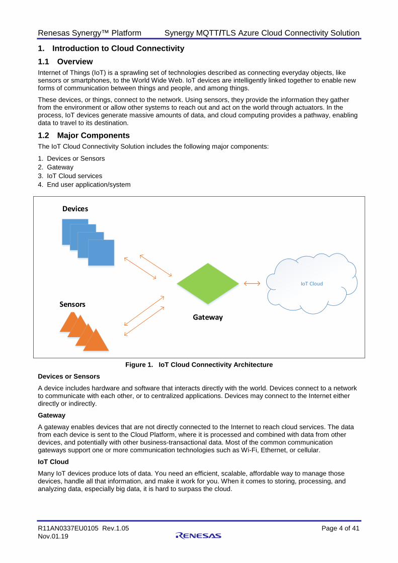
1.2 Major Components The IoT Cloud Connectivity Solution includes the following major components:
1. Devices or Sensors 2. Gateway 3. IoT Cloud services 4. End user application/system
IoT Cloud
Devices
SensorsGateway
Figure 1. IoT Cloud Connectivity Architecture Devices or Sensors A device includes hardware and software that interacts directly with the world. Devices connect to a network to communicate with each other, or to centralized applications. Devices may connect to the Internet either directly or indirectly.
Gateway A gateway enables devices that are not directly connected to the Internet to reach cloud services. The data from each device is sent to the Cloud Platform, where it is processed and combined with data from other devices, and potentially with other business-transactional data. Most of the common communication gateways support one or more communication technologies such as Wi-Fi, Ethernet, or cellular.
IoT Cloud Many IoT devices produce lots of data. You need an efficient, scalable, affordable way to manage those devices, handle all that information, and make it work for you. When it comes to storing, processing, and analyzing data, especially big data, it is hard to surpass the cloud.
Renesas Synergy™ Platform Synergy MQTT/TLS Azure Cloud Connectivity Solution
R11AN0337EU0105 Rev.1.05 Page 5 of 41 Nov.01.19
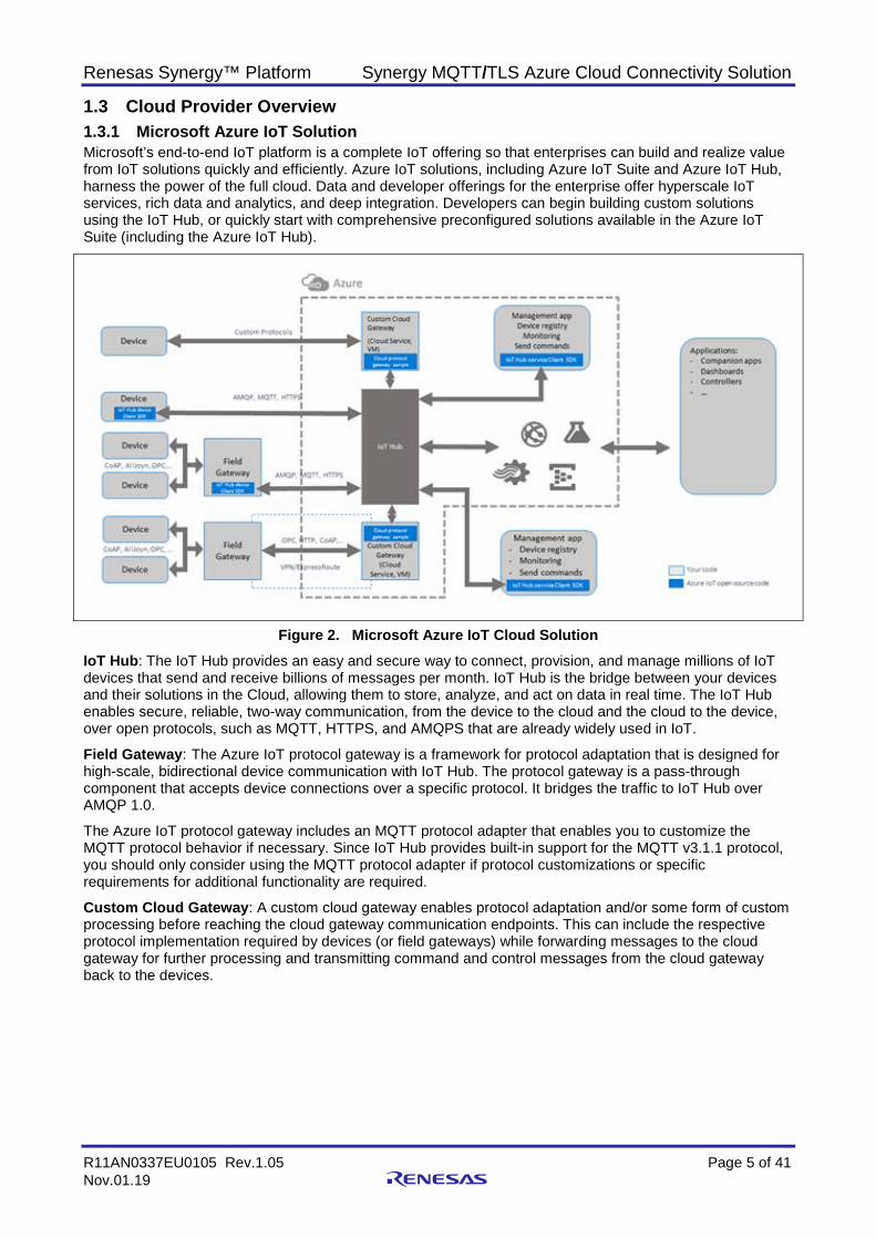
1.3 Cloud Provider Overview 1.3.1 Microsoft Azure IoT Solution Microsoft’s end-to-end IoT platform is a complete IoT offering so that enterprises can build and realize value from IoT solutions quickly and efficiently. Azure IoT solutions, including Azure IoT Suite and Azure IoT Hub, harness the power of the full cloud. Data and developer offerings for the enterprise offer hyperscale IoT services, rich data and analytics, and deep integration. Developers can begin building custom solutions using the IoT Hub, or quickly start with comprehensive preconfigured solutions available in the Azure IoT Suite (including the Azure IoT Hub).
Figure 2. Microsoft Azure IoT Cloud Solution IoT Hub: The IoT Hub provides an easy and secure way to connect, provision, and manage millions of IoT devices that send and receive billions of messages per month. IoT Hub is the bridge between your devices and their solutions in the Cloud, allowing them to store, analyze, and act on data in real time. The IoT Hub enables secure, reliable, two-way communication, from the device to the cloud and the cloud to the device, over open protocols, such as MQTT, HTTPS, and AMQPS that are already widely used in IoT.
Field Gateway: The Azure IoT protocol gateway is a framework for protocol adaptation that is designed for high-scale, bidirectional device communication with IoT Hub. The protocol gateway is a pass-through component that accepts device connections over a specific protocol. It bridges the traffic to IoT Hub over AMQP 1.0.
The Azure IoT protocol gateway includes an MQTT protocol adapter that enables you to customize the MQTT protocol behavior if necessary. Since IoT Hub provides built-in support for the MQTT v3.1.1 protocol, you should only consider using the MQTT protocol adapter if protocol customizations or specific requirements for additional functionality are required.
Custom Cloud Gateway: A custom cloud gateway enables protocol adaptation and/or some form of custom processing before reaching the cloud gateway communication endpoints. This can include the respective protocol implementation required by devices (or field gateways) while forwarding messages to the cloud gateway for further processing and transmitting command and control messages from the cloud gateway back to the devices.

Renesas Synergy™ Platform Synergy MQTT/TLS Azure Cloud Connectivity Solution
R11AN0337EU0105 Rev.1.05 Page 6 of 41 Nov.01.19
1.3.1.1 Key Features (1) Device Security Security is a critical concern when deploying and managing IoT devices. IoT Hub offers the following security features:
• The communication path between devices and Azure IoT Hub, or between gateways and Azure IoT Hub, is secured using industry-standard Transport Layer Security (TLS) with Azure IoT Hub authenticated using X.509 standard.
• To protect devices from unsolicited inbound connections, Azure IoT Hub does not open any connection to the device. The device initiates all connections.
• Azure IoT Hub durably stores messages for devices and waits for the device to connect. These commands are stored for two days, enabling devices connecting sporadically due to power or connectivity concerns, to receive these commands. Azure IoT Hub maintains a per-device queue for each device.
(2) Per-Device Key Authentication The following diagram shows authentication in the IoT Hub using security tokens.
Figure 3. Authentication using Security Tokens • The device prepares a shared access signature (SAS) token using the device endpoint, device id, and
primary key (generated as part of the device add to the IoT Hub). • When connecting to the IoT Hub, the device presents the SAS token as the password in the MQTT
CONNECT message. The username content is the combination of device endpoint, device name along with the additional Azure defined string.
• The IoT Hub verifies the SAS token and registers the device and connection gets established. • IoT hub provides Symmetric key for Data encryption. • The connection is closed when the SAS token expires. 1.4 MQTT Protocol Overview MQTT stands for Message Queuing Telemetry Transport. MQTT is a Client Server publish-subscribe messaging transport protocol. It is an extremely light weight, open, simple messaging protocol, designed for constrained devices, as well as low-bandwidth, high-latency, or unreliable networks. These characteristics make it ideal for use in many situations, including constrained environments, such as communication in Machine to Machine (M2M) and IoT contexts, where a small code footprint is required, and/or network bandwidth is at a premium.
A MQTT client can publish information to other clients through a broker. A client, if interested in a topic, can subscribe to the topic through the broker. A broker is responsible for authentication, authorization of clients, as well as delivering published messages to any of its clients who subscribe to the topic. In this publisher/subscriber model, multiple clients may publish data with the same topic. A client will receive the messages published if the client subscribes to the same topic.
Renesas Synergy™ Platform Synergy MQTT/TLS Azure Cloud Connectivity Solution
R11AN0337EU0105 Rev.1.05 Page 7 of 41 Nov.01.19
Thing 1
MQTTBroker
PUBLISH to Thing N/Data Thing 2
PUBLISH to Thing N/Data
Thing N
SUBSCRIBE to Thing 1/Data
SUBSCRIBE to Thing 2/Data
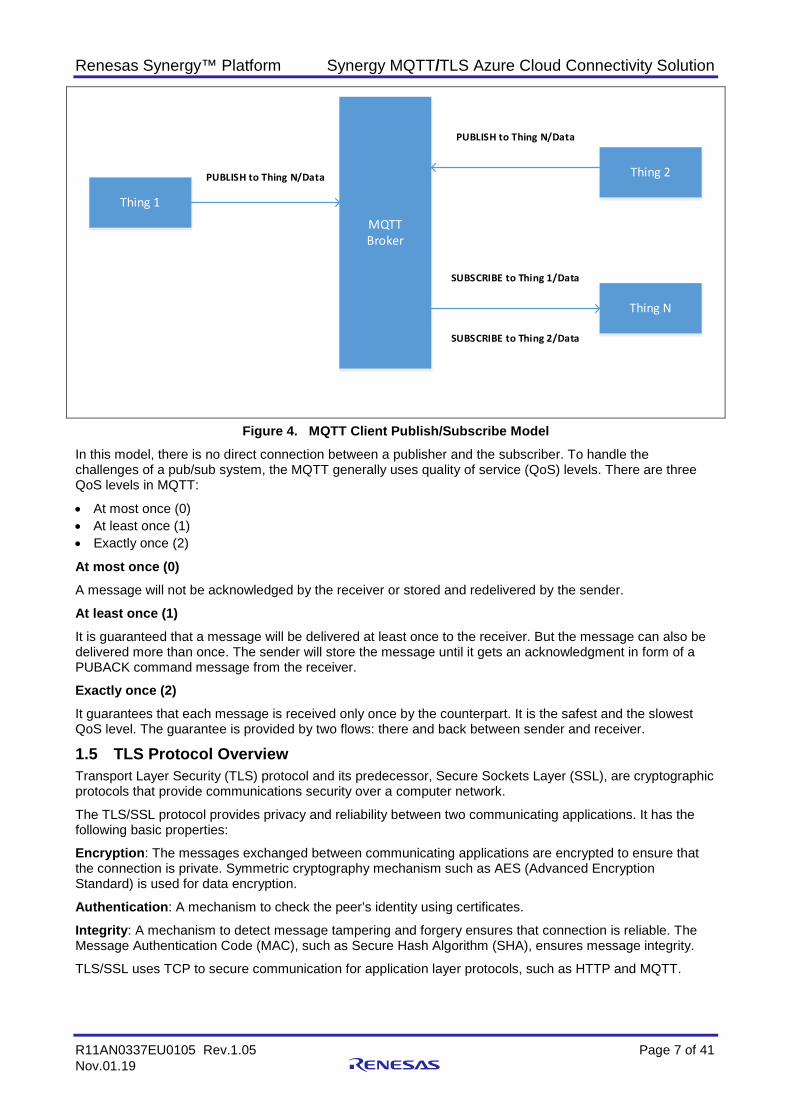
Figure 4. MQTT Client Publish/Subscribe Model In this model, there is no direct connection between a publisher and the subscriber. To handle the challenges of a pub/sub system, the MQTT generally uses quality of service (QoS) levels. There are three QoS levels in MQTT:
• At most once (0) • At least once (1) • Exactly once (2)
At most once (0) A message will not be acknowledged by the receiver or stored and redelivered by the sender.
At least once (1) It is guaranteed that a message will be delivered at least once to the receiver. But the message can also be delivered more than once. The sender will store the message until it gets an acknowledgment in form of a PUBACK command message from the receiver.
Exactly once (2) It guarantees that each message is received only once by the counterpart. It is the safest and the slowest QoS level. The guarantee is provided by two flows: there and back between sender and receiver.
1.5 TLS Protocol Overview Transport Layer Security (TLS) protocol and its predecessor, Secure Sockets Layer (SSL), are cryptographic protocols that provide communications security over a computer network.
The TLS/SSL protocol provides privacy and reliability between two communicating applications. It has the following basic properties:
Encryption: The messages exchanged between communicating applications are encrypted to ensure that the connection is private. Symmetric cryptography mechanism such as AES (Advanced Encryption Standard) is used for data encryption.
Authentication: A mechanism to check the peer’s identity using certificates.
Integrity: A mechanism to detect message tampering and forgery ensures that connection is reliable. The Message Authentication Code (MAC), such as Secure Hash Algorithm (SHA), ensures message integrity.
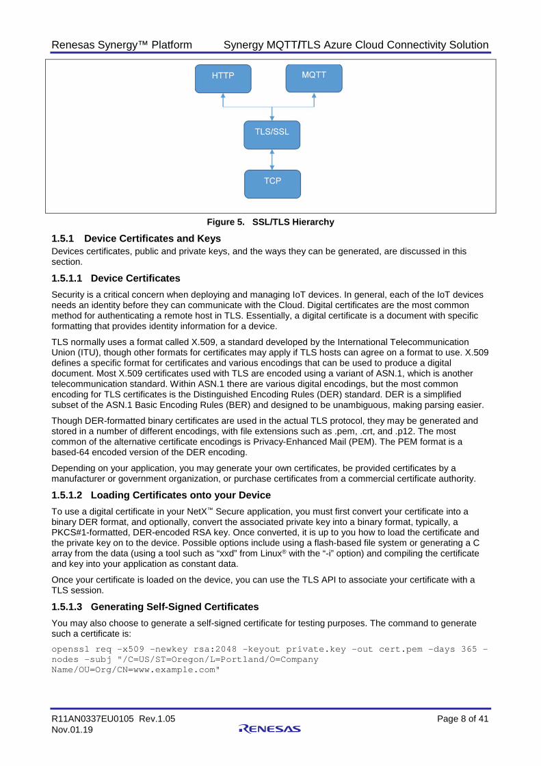
TLS/SSL uses TCP to secure communication for application layer protocols, such as HTTP and MQTT.
Renesas Synergy™ Platform Synergy MQTT/TLS Azure Cloud Connectivity Solution
R11AN0337EU0105 Rev.1.05 Page 8 of 41 Nov.01.19
Figure 5. SSL/TLS Hierarchy
1.5.1 Device Certificates and Keys Devices certificates, public and private keys, and the ways they can be generated, are discussed in this section.
1.5.1.1 Device Certificates Security is a critical concern when deploying and managing IoT devices. In general, each of the IoT devices needs an identity before they can communicate with the Cloud. Digital certificates are the most common method for authenticating a remote host in TLS. Essentially, a digital certificate is a document with specific formatting that provides identity information for a device.
TLS normally uses a format called X.509, a standard developed by the International Telecommunication Union (ITU), though other formats for certificates may apply if TLS hosts can agree on a format to use. X.509 defines a specific format for certificates and various encodings that can be used to produce a digital document. Most X.509 certificates used with TLS are encoded using a variant of ASN.1, which is another telecommunication standard. Within ASN.1 there are various digital encodings, but the most common encoding for TLS certificates is the Distinguished Encoding Rules (DER) standard. DER is a simplified subset of the ASN.1 Basic Encoding Rules (BER) and designed to be unambiguous, making parsing easier.
Though DER-formatted binary certificates are used in the actual TLS protocol, they may be generated and stored in a number of different encodings, with file extensions such as .pem, .crt, and .p12. The most common of the alternative certificate encodings is Privacy-Enhanced Mail (PEM). The PEM format is a based-64 encoded version of the DER encoding.
Depending on your application, you may generate your own certificates, be provided certificates by a manufacturer or government organization, or purchase certificates from a commercial certificate authority.
1.5.1.2 Loading Certificates onto your Device To use a digital certificate in your NetX™ Secure application, you must first convert your certificate into a binary DER format, and optionally, convert the associated private key into a binary format, typically, a PKCS#1-formatted, DER-encoded RSA key. Once converted, it is up to you how to load the certificate and the private key on to the device. Possible options include using a flash-based file system or generating a C array from the data (using a tool such as “xxd” from Linux® with the “-i” option) and compiling the certificate and key into your application as constant data.
Once your certificate is loaded on the device, you can use the TLS API to associate your certificate with a TLS session.
1.5.1.3 Generating Self-Signed Certificates You may also choose to generate a self-signed certificate for testing purposes. The command to generate such a certificate is: openssl req -x509 -newkey rsa:2048 -keyout private.key -out cert.pem -days 365 -nodes -subj "/C=US/ST=Oregon/L=Portland/O=Company Name/OU=Org/CN=www.example.com"
Renesas Synergy™ Platform Synergy MQTT/TLS Azure Cloud Connectivity Solution
R11AN0337EU0105 Rev.1.05 Page 9 of 41 Nov.01.19
In this situation, a self-signed certificate for www.example.com is generated. The certificate and private key files are cert.pem and private.key. You may generate a certificate for localhost by replacing www.example.com for localhost. In that case, pass localhost as the first argument to the installation script.
1.5.2 Device Security Recommendations The following security recommendations are not enforced by Cloud IoT Core but will help you secure your devices and connections.
• The private key should be kept secret. • Use TLS 1.2 when communicating with IoT Cloud and verify that the server certificate is valid using root
certificate authorities. • Each device should have a unique public/private key pair. If multiple devices share a single key and one
of those devices is compromised, an attacker could impersonate all the devices that have been configured with that one key.
• Keep the public key secure when registering it with Cloud IoT Core. If an attacker can tamper with the public key and trick the provisioner into swapping the public key and registering the wrong public key, the attacker will subsequently be able to authenticate on behalf of the device.
• The key pair is used to authenticate the device to Cloud IoT Core and should not be used for other purposed or protocols.
• Depending on the device’s ability to store keys securely, key pairs should be rotated periodically. When practical, all keys should be discarded when the device is reset.
• If your device runs an operating system, make sure you have a way to securely update it. Android Things provides a service for secure updates. For devices that don’t have an operating system, ensure that you can securely update the device’s software if security vulnerabilities are discovered after deployment.
2. Synergy MQTT/TLS Cloud Solution 2.1 MQTT Client Overview The NetX Duo MQTT Client module provides high-level APIs for a Message Queuing Telemetry Transport (MQTT) protocol-based client. The MQTT protocol works on top of TCP/IP and therefore the MQTT client is implemented on top of NetX Duo IP and NetX Duo Packet pool. NetX Duo IP attaches itself to the appropriate link layer frameworks, such as Ethernet, Wi-Fi, or cellular.
The NetX Duo MQTT client module can be used in normal or in secure mode. In normal mode, the communication between the MQTT client and broker is not secure. In secure mode, the communication between the MQTT client and broker is secured using the TLS protocol.
2.2 Design Considerations • By default, the MQTT client does not use TLS; communication is not secure between a MQTT client and
broker. • The Synergy MQTT client does not add the NetX Duo TLS session block. It only adds NetX Duo TLS
common block. This block defines/controls the common properties of NetX secure. • It is the responsibility of the user/application code to create the TLS session, configure the security
parameters, and load the relevant certificates manually under the TLS setup callback provided by nxd_mqtt_client_secure_connect () API.
2.2.1 Supported Features NetX Duo MQTT Client supports the following features:
• Compliant with OASIS MQTT Version 3.1.1 Oct 29, 2014. The specification can be found at http://mqtt.org/.
• Provides an option to enable/disable TLS for secure communication using NetX Secure in SSP. • Supports QoS and provides the ability to choose the levels that can be selected while publishing the
message. • Internally buffers and maintains the queue of received messages. • Provides a mechanism to register callback when a new message is received. • Provides a mechanism to register callback when connection with the broker is terminated.
Renesas Synergy™ Platform Synergy MQTT/TLS Azure Cloud Connectivity Solution
R11AN0337EU0105 Rev.1.05 Page 10 of 41 Nov.01.19
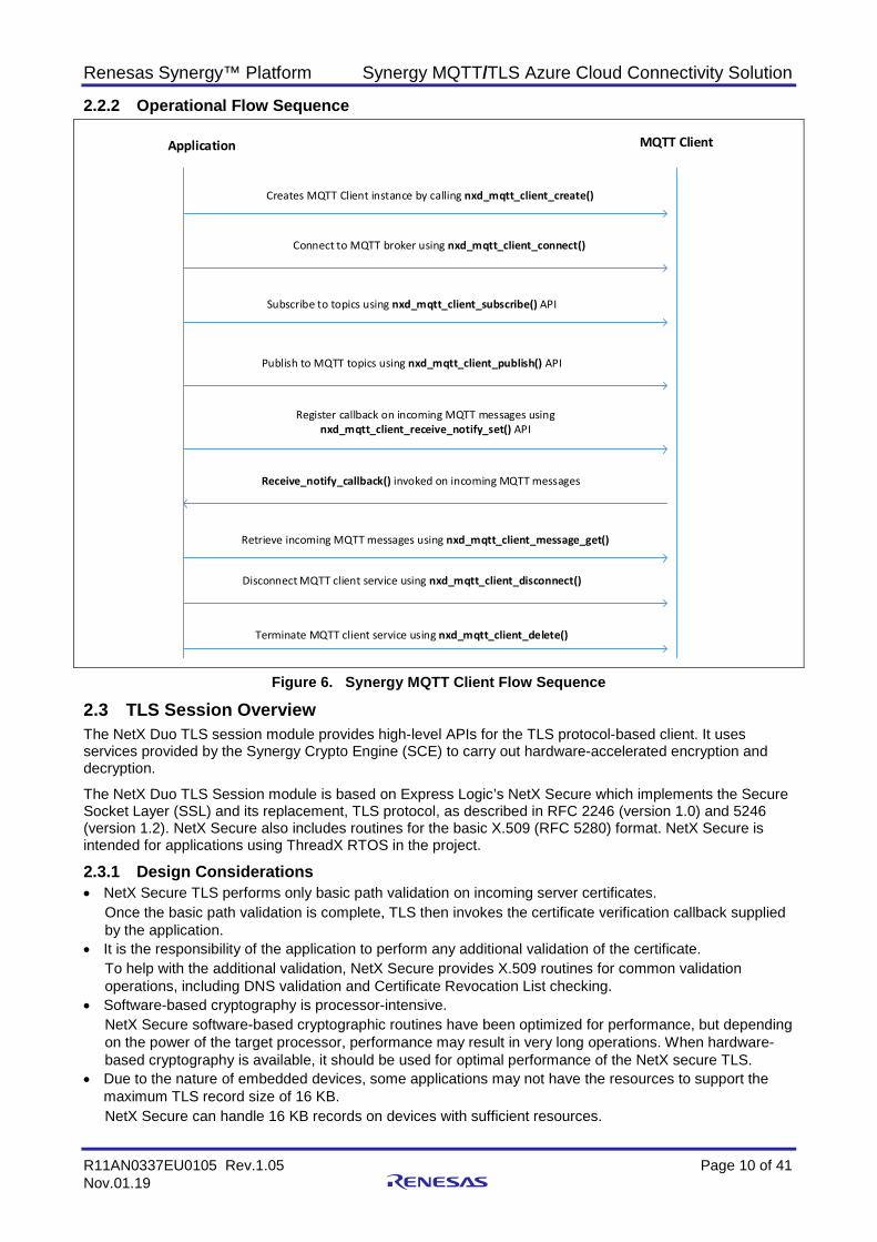
2.2.2 Operational Flow Sequence
Application MQTT Client
Creates MQTT Client instance by calling nxd_mqtt_client_create()
Connect to MQTT broker using nxd_mqtt_client_connect()
Subscribe to topics using nxd_mqtt_client_subscribe() API
Publish to MQTT topics using nxd_mqtt_client_publish() API
Register callback on incoming MQTT messages using nxd_mqtt_client_receive_notify_set() API
Receive_notify_callback() invoked on incoming MQTT messages
Retrieve incoming MQTT messages using nxd_mqtt_client_message_get()
Disconnect MQTT client service using nxd_mqtt_client_disconnect()
Terminate MQTT client service using nxd_mqtt_client_delete()
Figure 6. Synergy MQTT Client Flow Sequence
2.3 TLS Session Overview The NetX Duo TLS session module provides high-level APIs for the TLS protocol-based client. It uses services provided by the Synergy Crypto Engine (SCE) to carry out hardware-accelerated encryption and decryption.
The NetX Duo TLS Session module is based on Express Logic’s NetX Secure which implements the Secure Socket Layer (SSL) and its replacement, TLS protocol, as described in RFC 2246 (version 1.0) and 5246 (version 1.2). NetX Secure also includes routines for the basic X.509 (RFC 5280) format. NetX Secure is intended for applications using ThreadX RTOS in the project.
2.3.1 Design Considerations • NetX Secure TLS performs only basic path validation on incoming server certificates.
Once the basic path validation is complete, TLS then invokes the certificate verification callback supplied by the application.
• It is the responsibility of the application to perform any additional validation of the certificate. To help with the additional validation, NetX Secure provides X.509 routines for common validation operations, including DNS validation and Certificate Revocation List checking.
• Software-based cryptography is processor-intensive. NetX Secure software-based cryptographic routines have been optimized for performance, but depending on the power of the target processor, performance may result in very long operations. When hardware-based cryptography is available, it should be used for optimal performance of the NetX secure TLS.
• Due to the nature of embedded devices, some applications may not have the resources to support the maximum TLS record size of 16 KB. NetX Secure can handle 16 KB records on devices with sufficient resources.
Renesas Synergy™ Platform Synergy MQTT/TLS Azure Cloud Connectivity Solution
R11AN0337EU0105 Rev.1.05 Page 11 of 41 Nov.01.19
2.3.2 Supported Features • Support for RFC 2246 The Transport Layer Security (TLS) Protocol Version 1.0 • Support for RFC 5246 The TLS Protocol Version 1.2 • Support for RFC 5280 X.509 PKI Certificates (v3) • Support for RFC 3268 Advanced Encryption Standard (AES) Cipher suites for TLS • RFC 3447 Public-Key Cryptography Standards (PKCS) #1: RSA Cryptography Specifications Version 2.1 • RFC 2104 HMAC: Keyed-Hashing for Message Authentication • RFC 6234 US Secure Hash Algorithms (SHA and SHA-based HMAC and HKDF) • RFC 4279 Pre-Shared Key Cipher suites for TLS 2.3.3 Operational Flow Sequence This section describes the TLS handshake operational sequence.
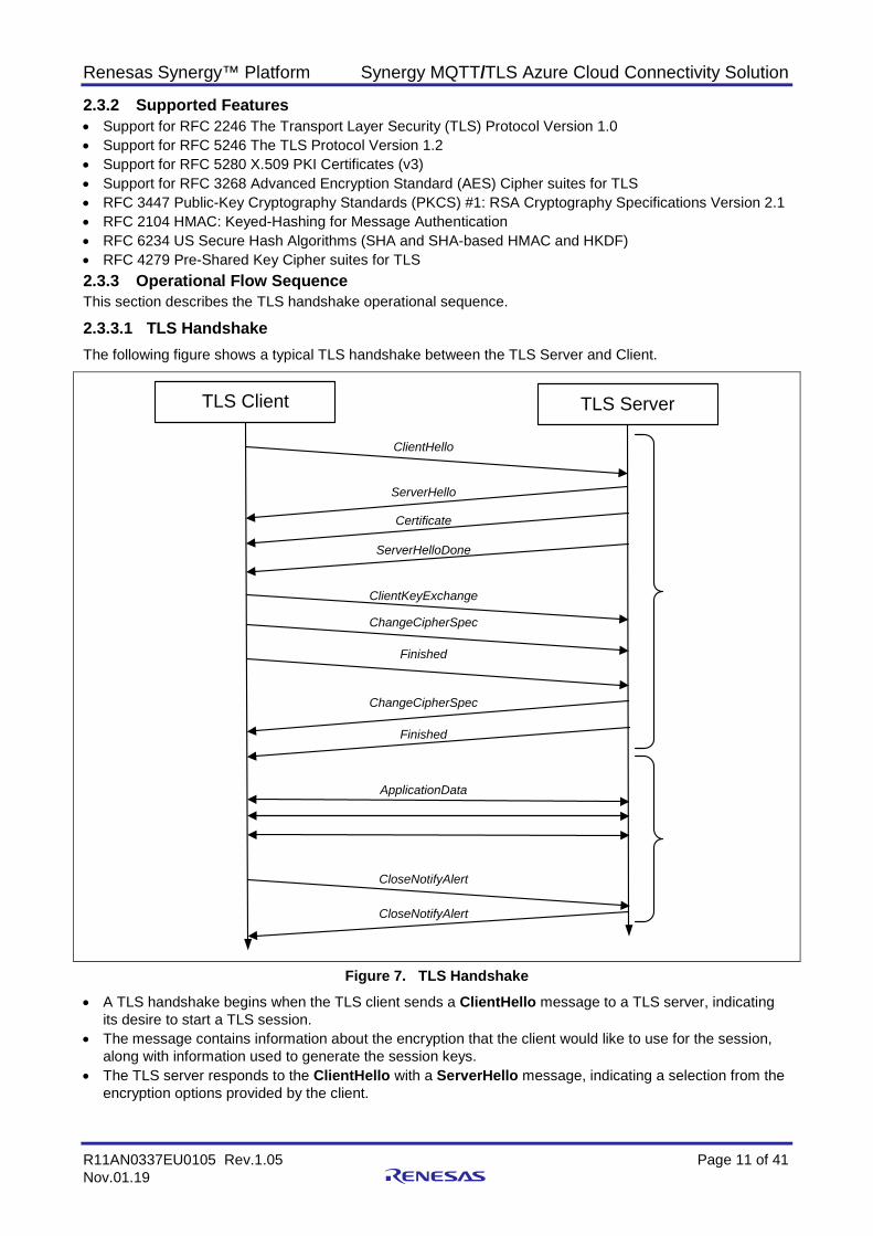
2.3.3.1 TLS Handshake The following figure shows a typical TLS handshake between the TLS Server and Client.
Figure 7. TLS Handshake • A TLS handshake begins when the TLS client sends a ClientHello message to a TLS server, indicating
its desire to start a TLS session. • The message contains information about the encryption that the client would like to use for the session,
along with information used to generate the session keys. • The TLS server responds to the ClientHello with a ServerHello message, indicating a selection from the
encryption options provided by the client.
TLS Client TLS Server
ClientHello
ServerHello
Certificate
ServerHelloDone
ClientKeyExchange
ChangeCipherSpec
Finished
ChangeCipherSpec
Finished
ApplicationData
CloseNotifyAlert
CloseNotifyAlert
Renesas Synergy™ Platform Synergy MQTT/TLS Azure Cloud Connectivity Solution
R11AN0337EU0105 Rev.1.05 Page 12 of 41 Nov.01.19
• It is followed by a Certificate message, in which the server provides a digital certificate to authenticate its identity to the client.
• Finally, the server sends a ServerHelloDone message to indicate it has no more messages to send. • Once Client has received all the server’s messages, it has enough information to generate the session
keys. TLS does this by creating a shared bit of random data called the Pre-Master Secret, which is a fixed size and is used as a seed to generate all the keys needed once encryption is enabled.
• The Pre-Master Secret is encrypted using the public key algorithm (such as RSA) specified in the Hello messages and the public key provided by the server in its certificate.
• The encrypted Pre-Master Secret is sent to the server in the clientKeyExchange message. The server, upon receiving the ClientKeyExchange message, decrypts the Pre-Master Secret using its private key and proceeds to generate the session keys in parallel with the TLS client.
• Once the session keys are generated, all further messages can be encrypted using the private-key algorithm (such as AES) selected in the Hello messages. One final un-encrypted message called ChangeCipherSpec is sent by both the client and server to indicate that all further messages will be encrypted.
• The first encrypted message sent by both the client and server is also the final TLS handshake message, called Finished. This message contains a hash of all the handshake messages received and sent. This hash is used to verify that none of the messages in the handshake have been tampered with or corrupted.
• Now the application begins sending and receiving data. All data — sent by either side — is first hashed using the hash algorithm chosen in the Hello messages, and then encrypted using the chosen private-key algorithm with the generated session keys.
• Finally, a TLS session can only be successfully ended if either the Client or Server chooses to do so. Both the client and server must send and process a CloseNotify alert for a successful session shutdown.
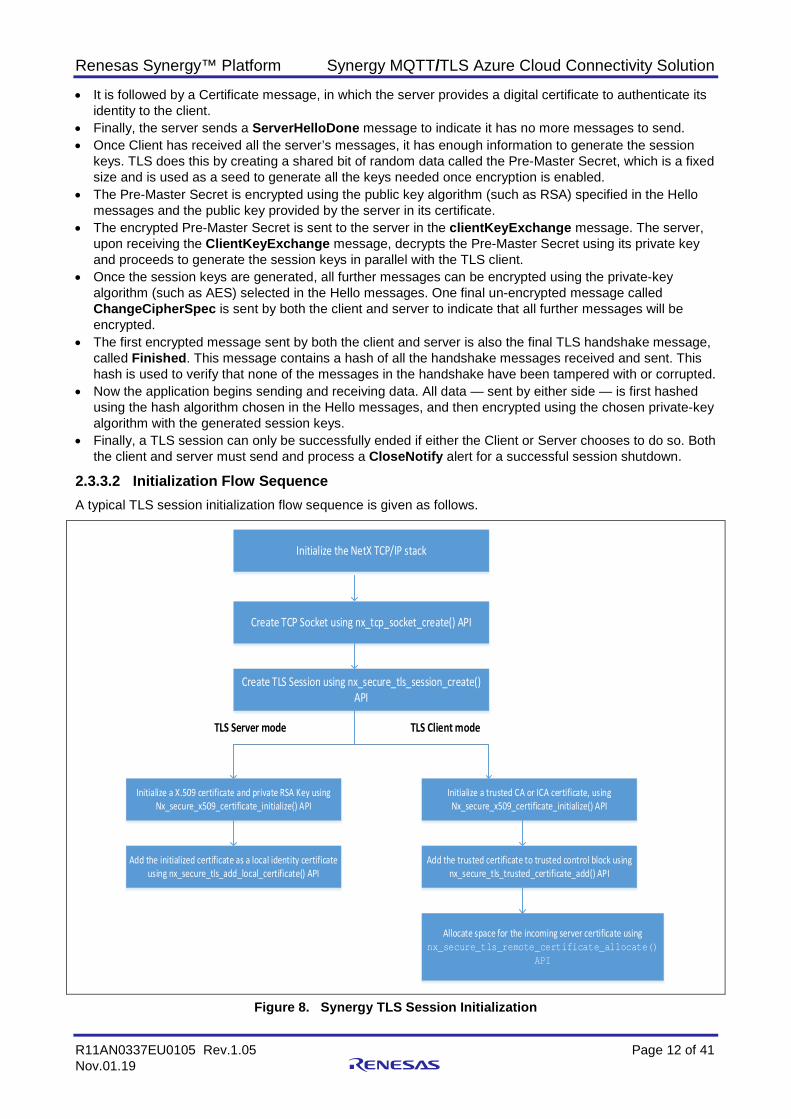
2.3.3.2 Initialization Flow Sequence A typical TLS session initialization flow sequence is given as follows.
Initialize the NetX TCP/IP stack
Create TCP Socket using nx_tcp_socket_create() API
Create TLS Session using nx_secure_tls_session_create() API
Initialize a X.509 certificate and private RSA Key using Nx_secure_x509_certificate_initialize() API
TLS Server mode TLS Client mode
Add the initialized certificate as a local identity certificate using nx_secure_tls_add_local_certificate() API
Initialize a trusted CA or ICA certificate, using Nx_secure_x509_certificate_initialize() API
Add the trusted certificate to trusted control block using nx_secure_tls_trusted_certificate_add() API
Allocate space for the incoming server certificate using nx_secure_tls_remote_certificate_allocate()
API
Figure 8. Synergy TLS Session Initialization
Renesas Synergy™ Platform Synergy MQTT/TLS Azure Cloud Connectivity Solution
R11AN0337EU0105 Rev.1.05 Page 13 of 41 Nov.01.19
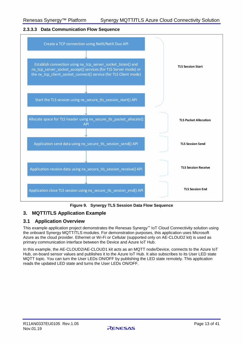
2.3.3.3 Data Communication Flow Sequence
Create a TCP connection using NetX/NetX Duo API
Establish connection using nx_tcp_server_socket_listen() and nx_tcp_server_socket_accept() services (for TLS Server mode) or the nx_tcp_client_socket_connect() service (for TLS Client mode)
Start the TLS session using nx_secure_tls_session_start() API
TLS Session Start
Allocate space for TLS header using nx_secure_tls_packet_allocate() API
TLS Packet Allocation
Application send data using nx_secure_tls_session_send() API TLS Session Send
Application receive data using nx_secure_tls_session_receive() API TLS Session Receive
Application close TLS session using nx_secure_tls_session_end() API TLS Session End
Figure 9. Synergy TLS Session Data Flow Sequence
3. MQTT/TLS Application Example 3.1 Application Overview This example application project demonstrates the Renesas Synergy™ IoT Cloud Connectivity solution using the onboard Synergy MQTT/TLS modules. For demonstration purposes, this application uses Microsoft Azure as the cloud provider. Ethernet or Wi-Fi or Cellular (supported only on AE-CLOUD2 kit) is used as primary communication interface between the Device and Azure IoT Hub.
In this example, the AE-CLOUD2/AE-CLOUD1 kit acts as an MQTT node/Device, connects to the Azure IoT Hub, on-board sensor values and publishes it to the Azure IoT Hub. It also subscribes to its User LED state MQTT topic. You can turn the User LEDs ON/OFF by publishing the LED state remotely. This application reads the updated LED state and turns the User LEDs ON/OFF.
Renesas Synergy™ Platform Synergy MQTT/TLS Azure Cloud Connectivity Solution
R11AN0337EU0105 Rev.1.05 Page 14 of 41 Nov.01.19
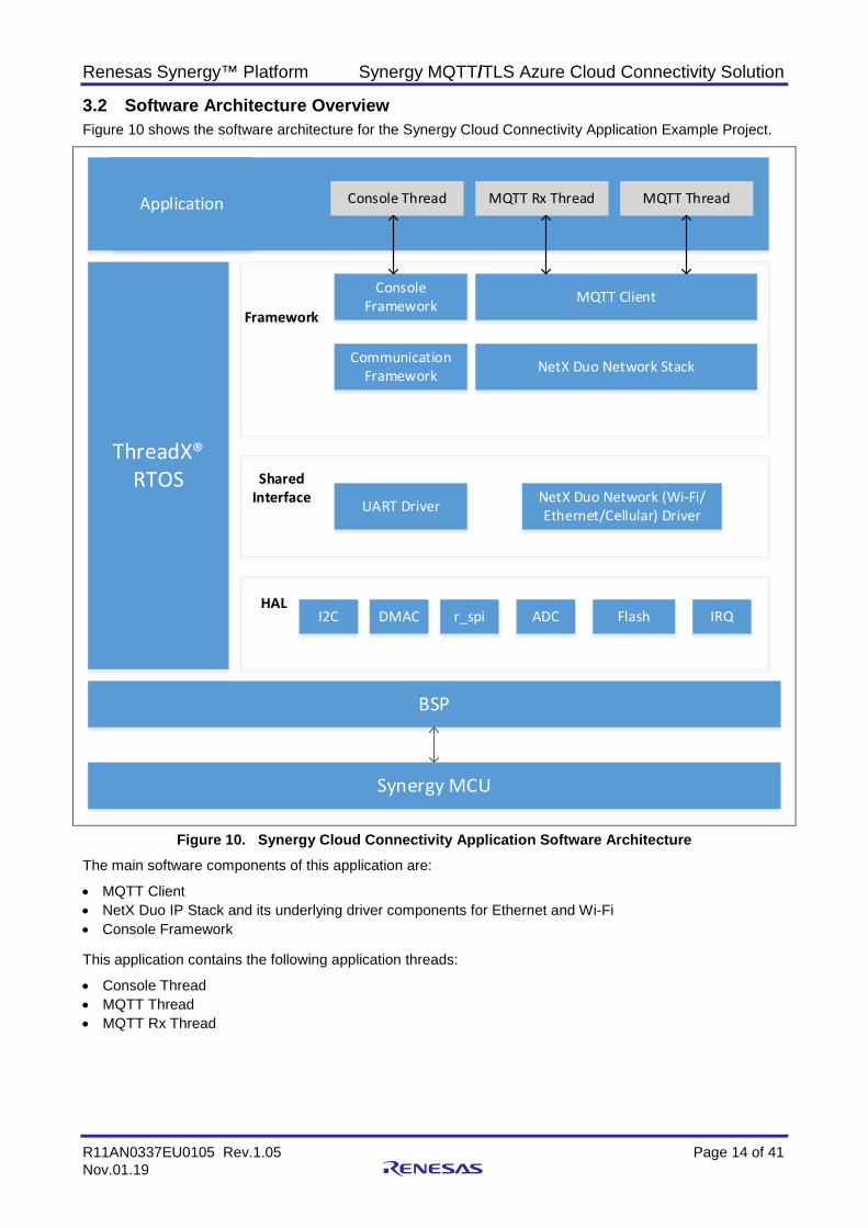
3.2 Software Architecture Overview Figure 10 shows the software architecture for the Synergy Cloud Connectivity Application Example Project.
Synergy MCU
BSP
ThreadX® RTOS
Application Console Thread
Framework
MQTT Rx Thread MQTT Thread
Console Framework
Communication Framework
Shared Interface
HAL
UART Driver
DMAC
MQTT Client
NetX Duo Network Stack
NetX Duo Network (Wi-Fi/Ethernet/Cellular) Driver
r_spi ADC Flash IRQI2C
Figure 10. Synergy Cloud Connectivity Application Software Architecture The main software components of this application are:
• MQTT Client • NetX Duo IP Stack and its underlying driver components for Ethernet and Wi-Fi • Console Framework This application contains the following application threads:
• Console Thread • MQTT Thread • MQTT Rx Thread
Renesas Synergy™ Platform Synergy MQTT/TLS Azure Cloud Connectivity Solution
R11AN0337EU0105 Rev.1.05 Page 15 of 41 Nov.01.19
3.2.1 Console Thread This thread handles the function related to the Command Line Interface (CLI). It uses the console framework, which in-turn uses the communication framework and its underlying USBX CDC device module components.
This thread reads the user inputs and stores them in the internal data flash. The stored information is read later by the MQTT Thread when it tries to run the Synergy Cloud connectivity demo.
This thread presents you with the following CLI command options.
• cwiz • Demo start/stop cwiz command option
Using this command option, you can select the following configurations: 1. Network interface such as Ethernet, Wi-Fi and its associated IP mode (DHCP/Static). 2. IoT cloud selection (Azure). 3. Dump the existing configuration from flash. 4. Exit the menu. Demo start/stop command option Using this command option, you can run/stop the Synergy Cloud Connectivity Demonstration.
3.2.2 MQTT Thread This thread is the main control handling the following major functions:
1. Initialize communication interface (Ethernet/Wi-Fi/Cellular). 2. Initialize IoT Cloud interface. 3. Read sensor data and publish the data periodically on MQTT topics. 4. Update the user LED state based on the type of MQTT message received. On wakeup, this thread periodically checks (every 5 seconds) for user input event flag state set once you enter the demonstration start/stop command on the CLI. If the demonstration start command is issued from the CLI, this thread will read the pre-configured user information from internal flash and checks its validity. If the content is valid, it then starts the Synergy Cloud connectivity demonstration. If a demo stop command is issued, it de-initializes the IoT cloud interface.
3.2.3 MQTT Rx Thread This thread handles the incoming MQTT messages from the MQTT broker. On receiving the new MQTT message, the user callback receive_notify_callback()will be invoked by the MQTT thread. This callback in turn sets the semaphore on which the MQTT Rx Thread is polling periodically.
On receiving the new MQTT message, it uses the nxd_mqtt_client_message_get() API to read the message, parse it, and act on it based on the type of the message received.
3.3 IoT Cloud Configuration (Azure) 3.3.1 Azure Web Portal Signup Microsoft Azure offers a free trial account (12 months) for each user. It is expected you have created an account on the Azure Cloud service before continuing to the next section.
To create an Azure account, open to the following link in your web browser: https://azure.microsoft.com/en-us/account/, fill in the required details and create a free user account.
Note: For identity verification, the user interface prompts you to add for the credit card information. The credit card will not be charged during the free trial period unless you upgrade. Inputting the details and accepting the agreement signup creates a free Trial account. Keep in mind while creating the Azure Web account and IoT Hub that screenshots may look slightly different from what is shown in this document. Users may need to navigate in the Azure environment to find the corresponding attribute while working on this project.
Renesas Synergy™ Platform Synergy MQTT/TLS Azure Cloud Connectivity Solution
R11AN0337EU0105 Rev.1.05 Page 16 of 41 Nov.01.19
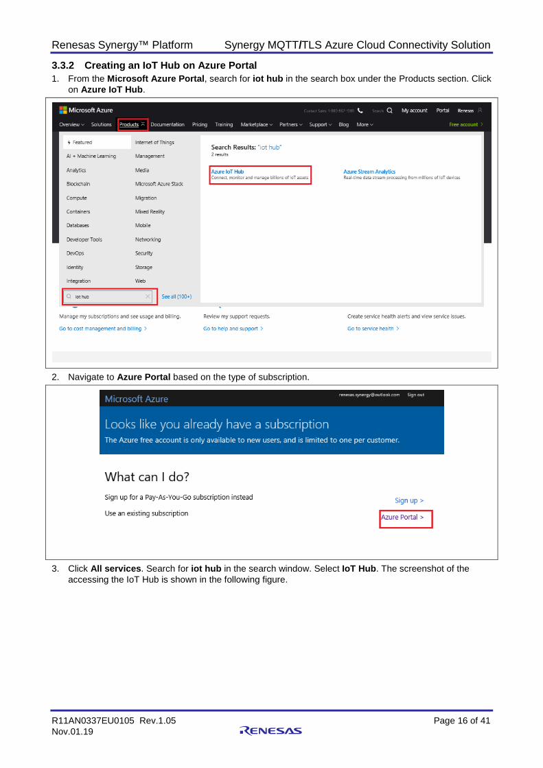
3.3.2 Creating an IoT Hub on Azure Portal 1. From the Microsoft Azure Portal, search for iot hub in the search box under the Products section. Click
on Azure IoT Hub.
2. Navigate to Azure Portal based on the type of subscription.
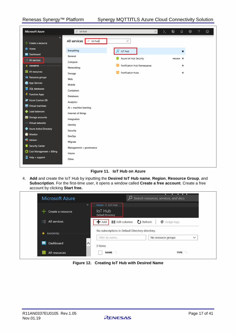
3. Click All services. Search for iot hub in the search window. Select IoT Hub. The screenshot of the accessing the IoT Hub is shown in the following figure.
Renesas Synergy™ Platform Synergy MQTT/TLS Azure Cloud Connectivity Solution
R11AN0337EU0105 Rev.1.05 Page 17 of 41 Nov.01.19
Figure 11. IoT Hub on Azure
4. Add and create the IoT Hub by inputting the Desired IoT Hub name, Region, Resource Group, and Subscription. For the first-time user, it opens a window called Create a free account. Create a free account by clicking Start free.
Figure 12. Creating IoT Hub with Desired Name
Renesas Synergy™ Platform Synergy MQTT/TLS Azure Cloud Connectivity Solution
R11AN0337EU0105 Rev.1.05 Page 18 of 41 Nov.01.19
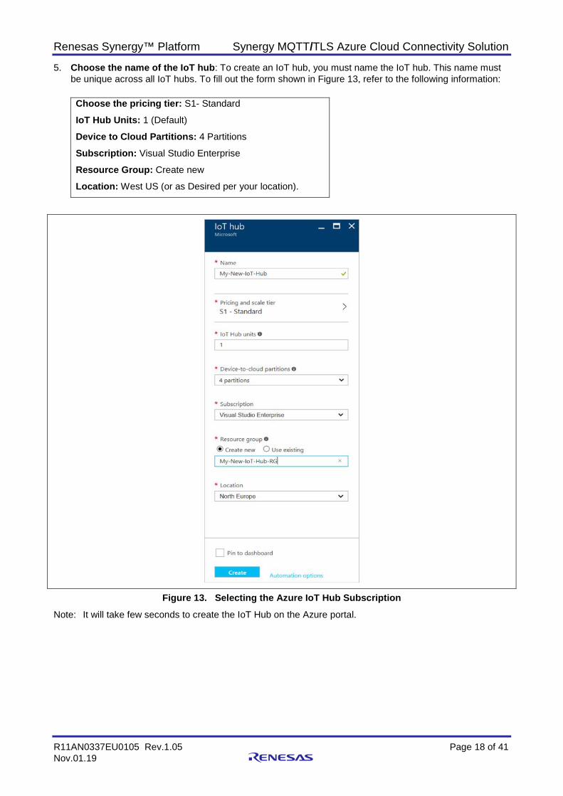
5. Choose the name of the IoT hub: To create an IoT hub, you must name the IoT hub. This name must be unique across all IoT hubs. To fill out the form shown in Figure 13, refer to the following information: Choose the pricing tier: S1- Standard
IoT Hub Units: 1 (Default)
Device to Cloud Partitions: 4 Partitions
Subscription: Visual Studio Enterprise
Resource Group: Create new
Location: West US (or as Desired per your location).
Figure 13. Selecting the Azure IoT Hub Subscription Note: It will take few seconds to create the IoT Hub on the Azure portal.
Renesas Synergy™ Platform Synergy MQTT/TLS Azure Cloud Connectivity Solution
R11AN0337EU0105 Rev.1.05 Page 19 of 41 Nov.01.19
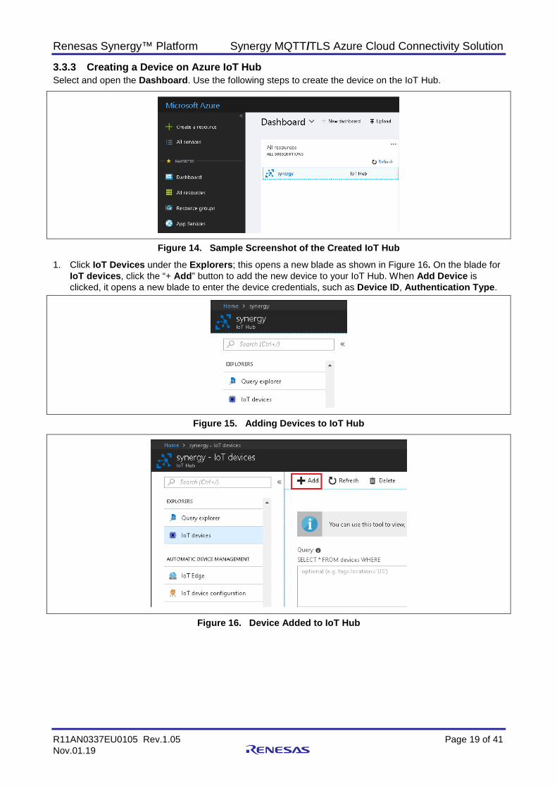
3.3.3 Creating a Device on Azure IoT Hub Select and open the Dashboard. Use the following steps to create the device on the IoT Hub.
Figure 14. Sample Screenshot of the Created IoT Hub
1. Click IoT Devices under the Explorers; this opens a new blade as shown in Figure 16. On the blade for IoT devices, click the “+ Add” button to add the new device to your IoT Hub. When Add Device is clicked, it opens a new blade to enter the device credentials, such as Device ID, Authentication Type.
Figure 15. Adding Devices to IoT Hub
Figure 16. Device Added to IoT Hub
Renesas Synergy™ Platform Synergy MQTT/TLS Azure Cloud Connectivity Solution
R11AN0337EU0105 Rev.1.05 Page 20 of 41 Nov.01.19
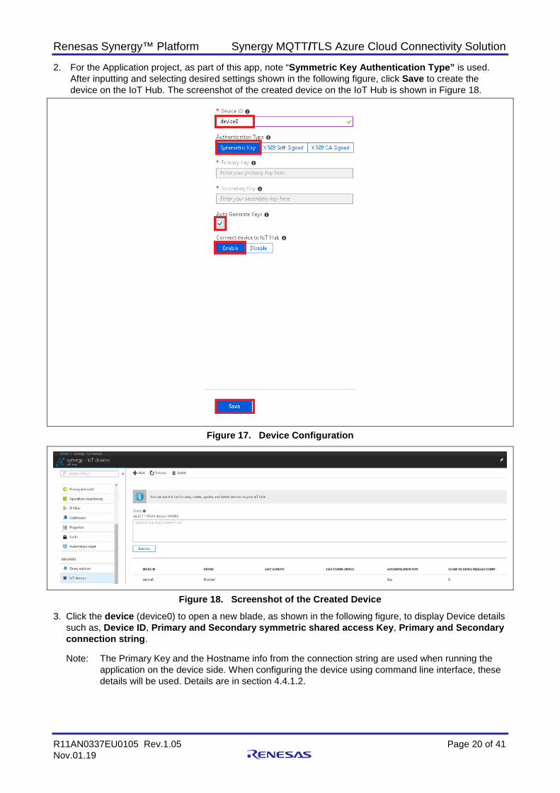
2. For the Application project, as part of this app, note “Symmetric Key Authentication Type” is used. After inputting and selecting desired settings shown in the following figure, click Save to create the device on the IoT Hub. The screenshot of the created device on the IoT Hub is shown in Figure 18.
Figure 17. Device Configuration
Figure 18. Screenshot of the Created Device
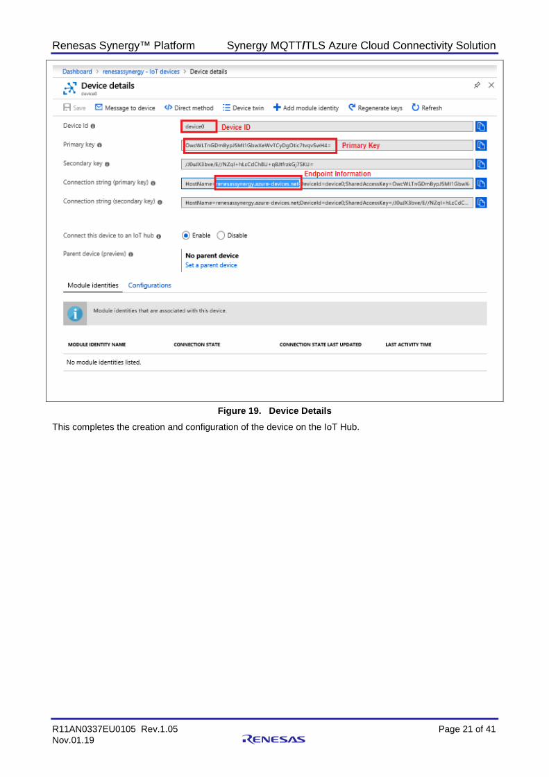
3. Click the device (device0) to open a new blade, as shown in the following figure, to display Device details such as, Device ID, Primary and Secondary symmetric shared access Key, Primary and Secondary connection string.
Note: The Primary Key and the Hostname info from the connection string are used when running the
application on the device side. When configuring the device using command line interface, these details will be used. Details are in section 4.4.1.2.
Renesas Synergy™ Platform Synergy MQTT/TLS Azure Cloud Connectivity Solution
R11AN0337EU0105 Rev.1.05 Page 21 of 41 Nov.01.19
Figure 19. Device Details This completes the creation and configuration of the device on the IoT Hub.
Renesas Synergy™ Platform Synergy MQTT/TLS Azure Cloud Connectivity Solution
R11AN0337EU0105 Rev.1.05 Page 22 of 41 Nov.01.19
4. Running the MQTT/TLS Application 4.1 Importing, Building, and Loading the Project See the Renesas Synergy™ Project Import Guide (r11an0023eu0121-synergy-ssp-import-guide.pdf), included in this package, for instructions to import the project into e2 studio, build, and run the project.
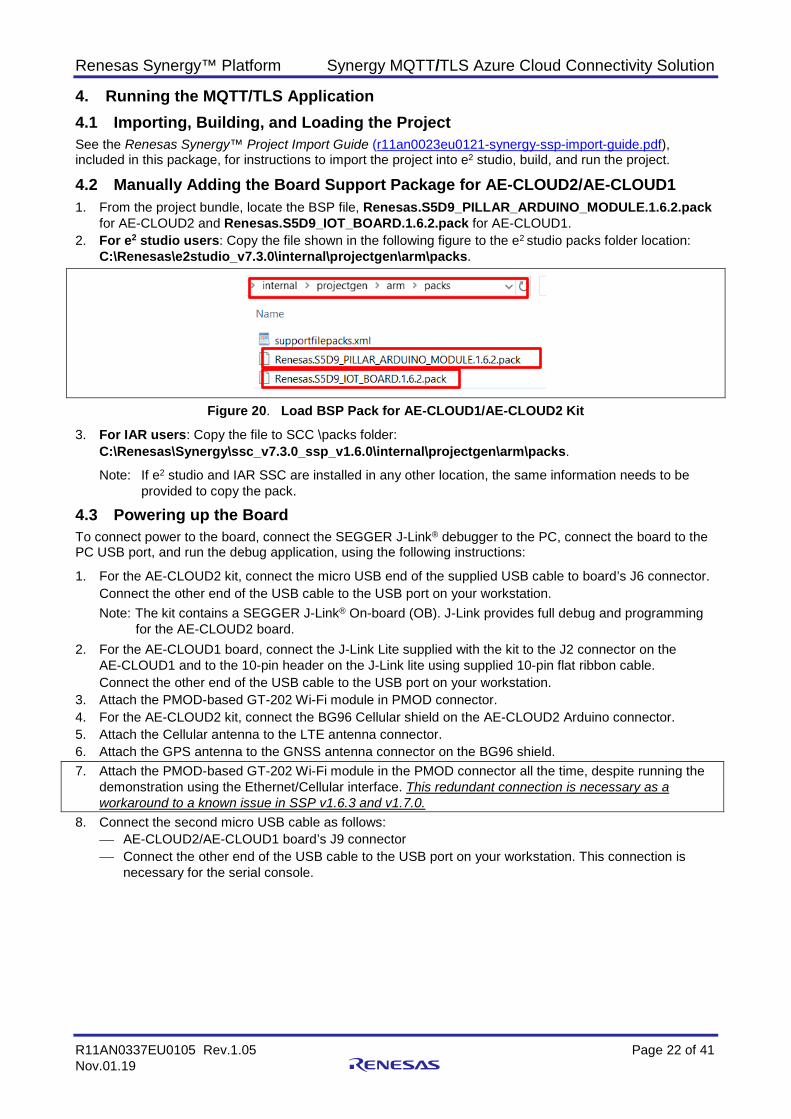
4.2 Manually Adding the Board Support Package for AE-CLOUD2/AE-CLOUD1 1. From the project bundle, locate the BSP file, Renesas.S5D9_PILLAR_ARDUINO_MODULE.1.6.2.pack
for AE-CLOUD2 and Renesas.S5D9_IOT_BOARD.1.6.2.pack for AE-CLOUD1. 2. For e2 studio users: Copy the file shown in the following figure to the e2 studio packs folder location:
C:\Renesas\e2studio_v7.3.0\internal\projectgen\arm\packs.
Figure 20. Load BSP Pack for AE-CLOUD1/AE-CLOUD2 Kit
3. For IAR users: Copy the file to SCC \packs folder: C:\Renesas\Synergy\ssc_v7.3.0_ssp_v1.6.0\internal\projectgen\arm\packs.
Note: If e2 studio and IAR SSC are installed in any other location, the same information needs to be provided to copy the pack.
4.3 Powering up the Board To connect power to the board, connect the SEGGER J-Link® debugger to the PC, connect the board to the PC USB port, and run the debug application, using the following instructions:
1. For the AE-CLOUD2 kit, connect the micro USB end of the supplied USB cable to board’s J6 connector. Connect the other end of the USB cable to the USB port on your workstation. Note: The kit contains a SEGGER J-Link® On-board (OB). J-Link provides full debug and programming
for the AE-CLOUD2 board. 2. For the AE-CLOUD1 board, connect the J-Link Lite supplied with the kit to the J2 connector on the
AE-CLOUD1 and to the 10-pin header on the J-Link lite using supplied 10-pin flat ribbon cable. Connect the other end of the USB cable to the USB port on your workstation.
3. Attach the PMOD-based GT-202 Wi-Fi module in PMOD connector. 4. For the AE-CLOUD2 kit, connect the BG96 Cellular shield on the AE-CLOUD2 Arduino connector. 5. Attach the Cellular antenna to the LTE antenna connector. 6. Attach the GPS antenna to the GNSS antenna connector on the BG96 shield. 7. Attach the PMOD-based GT-202 Wi-Fi module in the PMOD connector all the time, despite running the
demonstration using the Ethernet/Cellular interface. This redundant connection is necessary as a workaround to a known issue in SSP v1.6.3 and v1.7.0.
8. Connect the second micro USB cable as follows: AE-CLOUD2/AE-CLOUD1 board’s J9 connector Connect the other end of the USB cable to the USB port on your workstation. This connection is
necessary for the serial console.
Renesas Synergy™ Platform Synergy MQTT/TLS Azure Cloud Connectivity Solution
R11AN0337EU0105 Rev.1.05 Page 23 of 41 Nov.01.19
4.4 Connect to Azure IoT Cloud The following instructions show how to run the Synergy Cloud connectivity application project and connect to the Azure IoT Cloud.
Note: At this stage, it is assumed that you have completed the instructions in section 3.3 to create an Azure IoT account and have set up your device on the Azure IoT Hub.
• The instructions below show how the command line interface can be used to configure the boards, depending upon the desired interface for Cloud connectivity.
• While running the application on these boards, connectivity is done using one interface at a time (Ethernet or Wi-Fi or Cellular). Users must configure the desired interface to run the application. If you use Ethernet, be aware that Wi-Fi or Cellular is not available, and vice-versa.
• Users need to note that the CLI screenshots shown may not apply to all the boards. For example, cellular is not applicable to AE-CLOUD1 board:
Board Ethernet Wi-Fi Cellular AE-CLOUD1 Supported Supported Not Supported AE-CLOUD2 Supported Supported Supported
1. If you have not already done so, complete section 3 and then go to section 4.3 to power up and load the
project on to the AE-CLOUD2/AE-CLOUD1 kit. 2. Connect the USB Device port of the kit to the test PC. It will be automatically detected as an USB Serial
device in case of Windows 10 PC. In case of Windows 7/8 PC, refer to the following installation guide to load the Synergy USB CDC driver: https://en-support.renesas.com/knowledgeBase/16977397 and www.renesas.com/en-us/products/synergy/software/add-ons/usb-cdc-drivers.html.
3. Open the serial console application, such as Tera Term, to connect to the AE-CLOUD2/AE-CLOUD1 kit. The default Tera Term settings are 8-N-1, and the baud rate is 9600.
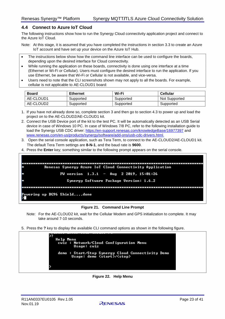
4. Press the Enter key; something similar to the following prompt appears on the serial console.
Figure 21. Command Line Prompt Note: For the AE-CLOUD2 kit, wait for the Cellular Modem and GPS initialization to complete. It may
take around 7-10 seconds. 5. Press the ? key to display the available CLI command options as shown in the following figure.
Figure 22. Help Menu
Renesas Synergy™ Platform Synergy MQTT/TLS Azure Cloud Connectivity Solution
R11AN0337EU0105 Rev.1.05 Page 24 of 41 Nov.01.19
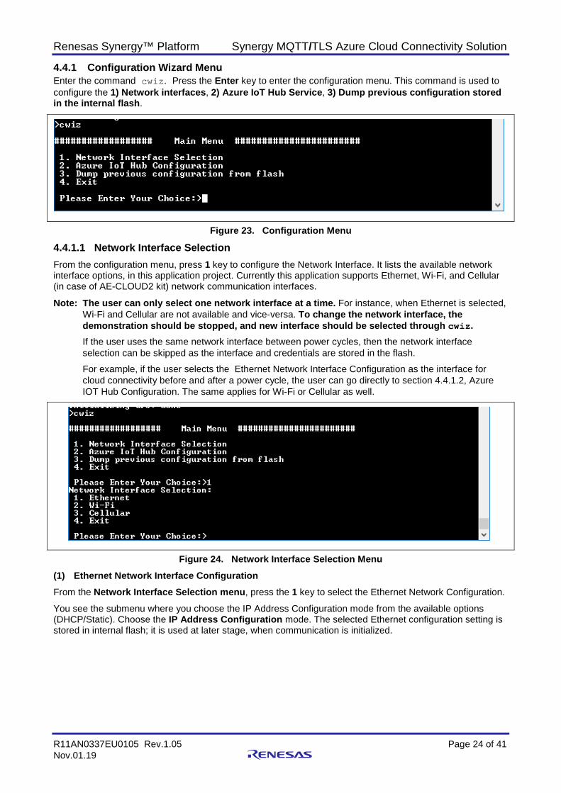
4.4.1 Configuration Wizard Menu Enter the command cwiz. Press the Enter key to enter the configuration menu. This command is used to configure the 1) Network interfaces, 2) Azure IoT Hub Service, 3) Dump previous configuration stored in the internal flash.
Figure 23. Configuration Menu
4.4.1.1 Network Interface Selection From the configuration menu, press 1 key to configure the Network Interface. It lists the available network interface options, in this application project. Currently this application supports Ethernet, Wi-Fi, and Cellular (in case of AE-CLOUD2 kit) network communication interfaces.
Note: The user can only select one network interface at a time. For instance, when Ethernet is selected, Wi-Fi and Cellular are not available and vice-versa. To change the network interface, the demonstration should be stopped, and new interface should be selected through cwiz. If the user uses the same network interface between power cycles, then the network interface selection can be skipped as the interface and credentials are stored in the flash.
For example, if the user selects the Ethernet Network Interface Configuration as the interface for cloud connectivity before and after a power cycle, the user can go directly to section 4.4.1.2, Azure IOT Hub Configuration. The same applies for Wi-Fi or Cellular as well.
Figure 24. Network Interface Selection Menu (1) Ethernet Network Interface Configuration From the Network Interface Selection menu, press the 1 key to select the Ethernet Network Configuration.
You see the submenu where you choose the IP Address Configuration mode from the available options (DHCP/Static). Choose the IP Address Configuration mode. The selected Ethernet configuration setting is stored in internal flash; it is used at later stage, when communication is initialized.

Renesas Synergy™ Platform Synergy MQTT/TLS Azure Cloud Connectivity Solution
R11AN0337EU0105 Rev.1.05 Page 25 of 41 Nov.01.19
Figure 25. Ethernet Network Interface Configuration Menu – DHCP Configuration
Figure 26. Ethernet Network Interface Configuration Menu – Static IP Configuration Note: The Ethernet Static IP configuration does not work with the default project. User needs to add
the NetX duo source code to the project. This issue will be fixed in future release.
Renesas Synergy™ Platform Synergy MQTT/TLS Azure Cloud Connectivity Solution
R11AN0337EU0105 Rev.1.05 Page 26 of 41 Nov.01.19
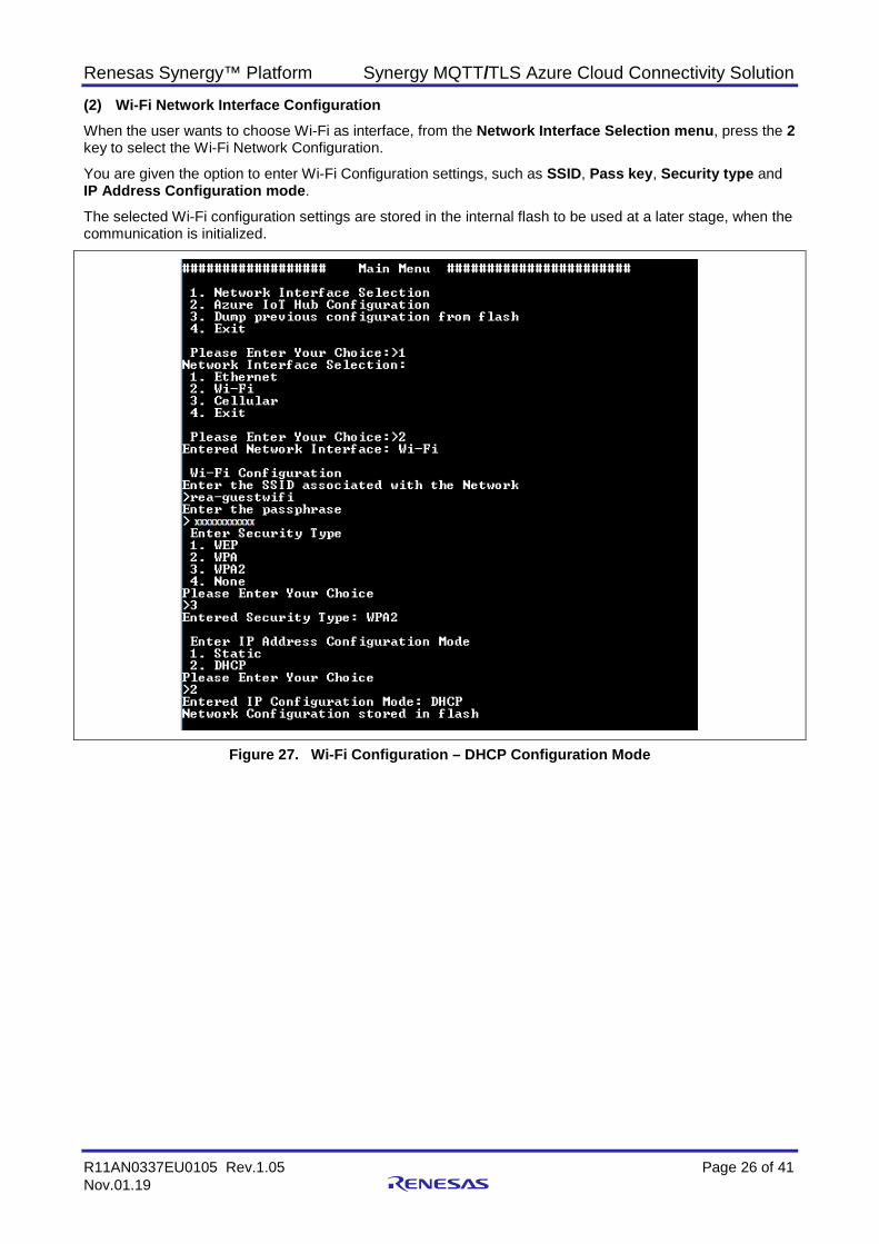
(2) Wi-Fi Network Interface Configuration When the user wants to choose Wi-Fi as interface, from the Network Interface Selection menu, press the 2 key to select the Wi-Fi Network Configuration.
You are given the option to enter Wi-Fi Configuration settings, such as SSID, Pass key, Security type and IP Address Configuration mode.
The selected Wi-Fi configuration settings are stored in the internal flash to be used at a later stage, when the communication is initialized.
Figure 27. Wi-Fi Configuration – DHCP Configuration Mode
Renesas Synergy™ Platform Synergy MQTT/TLS Azure Cloud Connectivity Solution
R11AN0337EU0105 Rev.1.05 Page 27 of 41 Nov.01.19
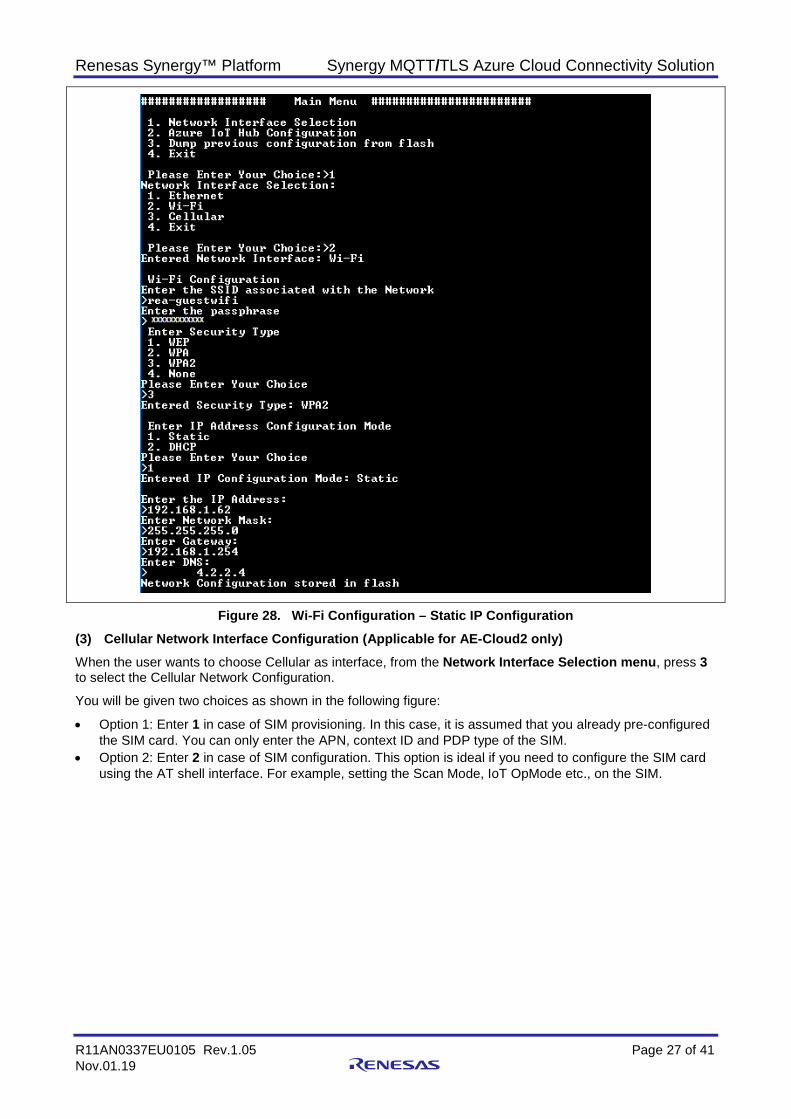
Figure 28. Wi-Fi Configuration – Static IP Configuration (3) Cellular Network Interface Configuration (Applicable for AE-Cloud2 only) When the user wants to choose Cellular as interface, from the Network Interface Selection menu, press 3 to select the Cellular Network Configuration.
You will be given two choices as shown in the following figure:
• Option 1: Enter 1 in case of SIM provisioning. In this case, it is assumed that you already pre-configured the SIM card. You can only enter the APN, context ID and PDP type of the SIM.
• Option 2: Enter 2 in case of SIM configuration. This option is ideal if you need to configure the SIM card using the AT shell interface. For example, setting the Scan Mode, IoT OpMode etc., on the SIM.
Renesas Synergy™ Platform Synergy MQTT/TLS Azure Cloud Connectivity Solution
R11AN0337EU0105 Rev.1.05 Page 28 of 41 Nov.01.19
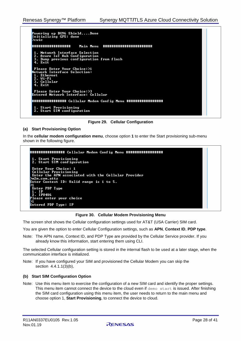
Figure 29. Cellular Configuration (a) Start Provisioning Option In the cellular modem configuration menu, choose option 1 to enter the Start provisioning sub-menu shown in the following figure.
Figure 30. Cellular Modem Provisioning Menu The screen shot shows the Cellular configuration settings used for AT&T (USA Carrier) SIM card.
You are given the option to enter Cellular Configuration settings, such as APN, Context ID, PDP type.
Note: The APN name, Context ID, and PDP Type are provided by the Cellular Service provider. If you already know this information, start entering them using CLI.
The selected Cellular configuration setting is stored in the internal flash to be used at a later stage, when the communication interface is initialized.
Note: If you have configured your SIM and provisioned the Cellular Modem you can skip the section 4.4.1.1(3)(b),
(b) Start SIM Configuration Option Note: Use this menu item to exercise the configuration of a new SIM card and identify the proper settings.
This menu item cannot connect the device to the cloud even if demo start is issued. After finishing the SIM card configuration using this menu item, the user needs to return to the main menu and choose option 1, Start Provisioning, to connect the device to cloud.
Renesas Synergy™ Platform Synergy MQTT/TLS Azure Cloud Connectivity Solution
R11AN0337EU0105 Rev.1.05 Page 29 of 41 Nov.01.19
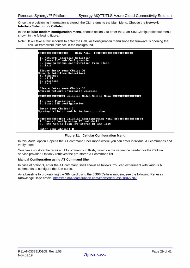
Once the provisioning information is stored, the CLI returns to the Main Menu. Choose the Network Interface Selection -> Cellular. In the cellular modem configuration menu, choose option 2 to enter the Start SIM Configuration submenu shown in the following figure.
Note: It will take a few seconds to enter the Cellular Configuration menu since the firmware is opening the cellular framework instance in the background.
Figure 31. Cellular Configuration Menu In this Mode, option 1 opens the AT command Shell mode where you can enter individual AT commands and verify them.
You can also store the required AT commands in flash, based on the sequence needed for the Cellular service provider. Option 2 retrieves the pre-stored AT command list.
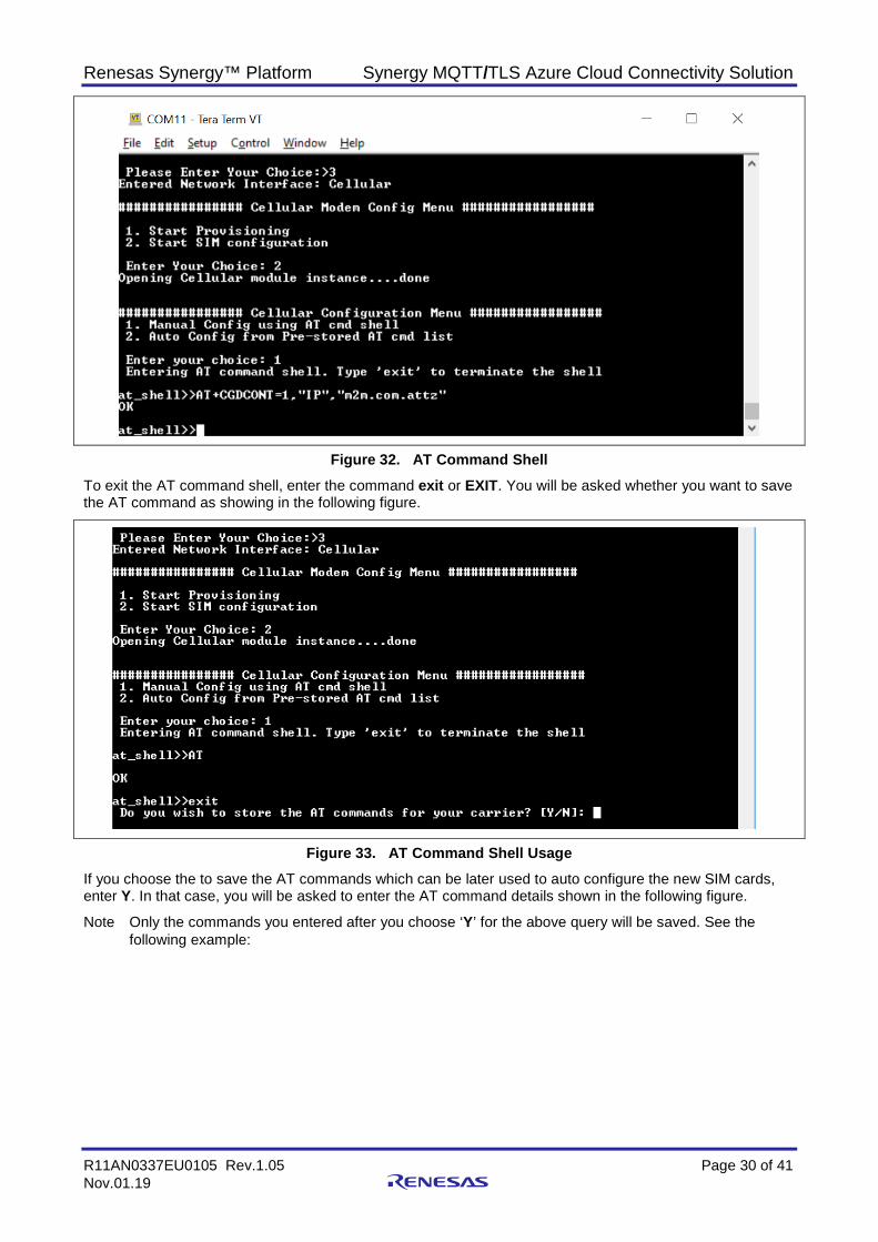
Manual Configuration using AT Command Shell In case of option 1, enter the AT command shell shown as follows. You can experiment with various AT commands to configure the SIM cards.
As a baseline to provisioning the SIM card using the BG96 Cellular modem, see the following Renesas Knowledge Base article: https://en.na4.teamsupport.com/knowledgeBase/18027787
Renesas Synergy™ Platform Synergy MQTT/TLS Azure Cloud Connectivity Solution
R11AN0337EU0105 Rev.1.05 Page 30 of 41 Nov.01.19
Figure 32. AT Command Shell To exit the AT command shell, enter the command exit or EXIT. You will be asked whether you want to save the AT command as showing in the following figure.
Figure 33. AT Command Shell Usage If you choose the to save the AT commands which can be later used to auto configure the new SIM cards, enter Y. In that case, you will be asked to enter the AT command details shown in the following figure.
Note Only the commands you entered after you choose ‘Y’ for the above query will be saved. See the following example:
Renesas Synergy™ Platform Synergy MQTT/TLS Azure Cloud Connectivity Solution
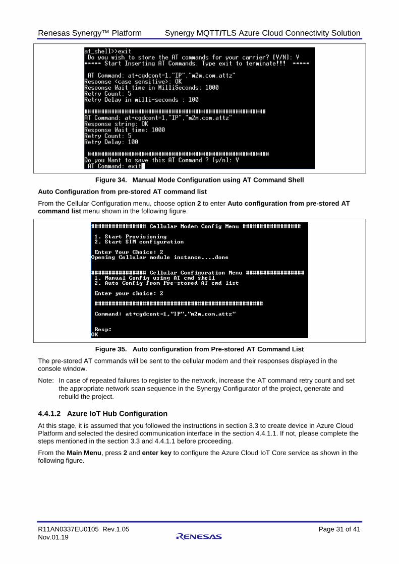
R11AN0337EU0105 Rev.1.05 Page 31 of 41 Nov.01.19
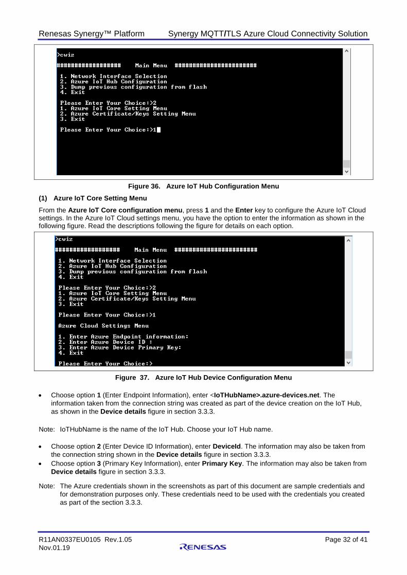
Figure 34. Manual Mode Configuration using AT Command Shell Auto Configuration from pre-stored AT command list From the Cellular Configuration menu, choose option 2 to enter Auto configuration from pre-stored AT command list menu shown in the following figure.
Figure 35. Auto configuration from Pre-stored AT Command List The pre-stored AT commands will be sent to the cellular modem and their responses displayed in the console window.
Note: In case of repeated failures to register to the network, increase the AT command retry count and set the appropriate network scan sequence in the Synergy Configurator of the project, generate and rebuild the project.
4.4.1.2 Azure IoT Hub Configuration At this stage, it is assumed that you followed the instructions in section 3.3 to create device in Azure Cloud Platform and selected the desired communication interface in the section 4.4.1.1. If not, please complete the steps mentioned in the section 3.3 and 4.4.1.1 before proceeding.
From the Main Menu, press 2 and enter key to configure the Azure Cloud IoT Core service as shown in the following figure.
Renesas Synergy™ Platform Synergy MQTT/TLS Azure Cloud Connectivity Solution
R11AN0337EU0105 Rev.1.05 Page 32 of 41 Nov.01.19
Figure 36. Azure IoT Hub Configuration Menu (1) Azure IoT Core Setting Menu From the Azure IoT Core configuration menu, press 1 and the Enter key to configure the Azure IoT Cloud settings. In the Azure IoT Cloud settings menu, you have the option to enter the information as shown in the following figure. Read the descriptions following the figure for details on each option.
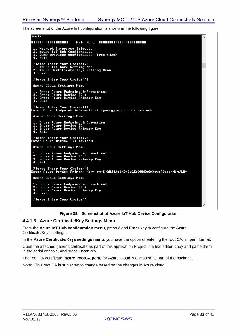
Figure 37. Azure IoT Hub Device Configuration Menu • Choose option 1 (Enter Endpoint Information), enter <IoTHubName>.azure-devices.net. The
information taken from the connection string was created as part of the device creation on the IoT Hub, as shown in the Device details figure in section 3.3.3.
Note: IoTHubName is the name of the IoT Hub. Choose your IoT Hub name. • Choose option 2 (Enter Device ID Information), enter DeviceId. The information may also be taken from
the connection string shown in the Device details figure in section 3.3.3. • Choose option 3 (Primary Key Information), enter Primary Key. The information may also be taken from
Device details figure in section 3.3.3. Note: The Azure credentials shown in the screenshots as part of this document are sample credentials and
for demonstration purposes only. These credentials need to be used with the credentials you created as part of the section 3.3.3.
Renesas Synergy™ Platform Synergy MQTT/TLS Azure Cloud Connectivity Solution
R11AN0337EU0105 Rev.1.05 Page 33 of 41 Nov.01.19
The screenshot of the Azure IoT configuration is shown in the following figure.
Figure 38. Screenshot of Azure IoT Hub Device Configuration
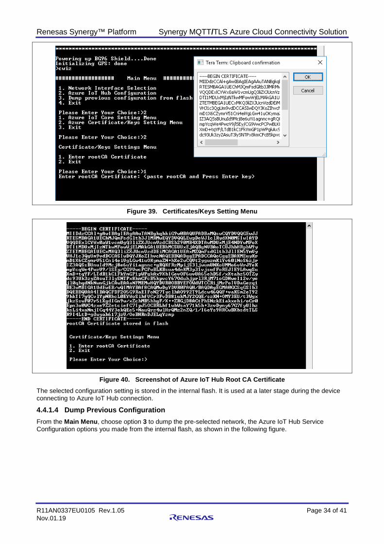
4.4.1.3 Azure Certificate/Key Settings Menu From the Azure IoT Hub configuration menu, press 2 and Enter key to configure the Azure Certificate/Keys settings.
In the Azure Certificate/Keys settings menu, you have the option of entering the root CA, in .pem format.
Open the attached generic certificate as part of this application Project in a text editor, copy and paste them in the serial console, and press Enter key.
The root CA certificate (azure_rootCA.pem) for Azure Cloud is enclosed as part of the package.
Note: This root CA is subjected to change based on the changes in Azure cloud.
Renesas Synergy™ Platform Synergy MQTT/TLS Azure Cloud Connectivity Solution
R11AN0337EU0105 Rev.1.05 Page 34 of 41 Nov.01.19
Figure 39. Certificates/Keys Setting Menu
Figure 40. Screenshot of Azure IoT Hub Root CA Certificate The selected configuration setting is stored in the internal flash. It is used at a later stage during the device connecting to Azure IoT Hub connection.
4.4.1.4 Dump Previous Configuration From the Main Menu, choose option 3 to dump the pre-selected network, the Azure IoT Hub Service Configuration options you made from the internal flash, as shown in the following figure.
Renesas Synergy™ Platform Synergy MQTT/TLS Azure Cloud Connectivity Solution
R11AN0337EU0105 Rev.1.05 Page 35 of 41 Nov.01.19
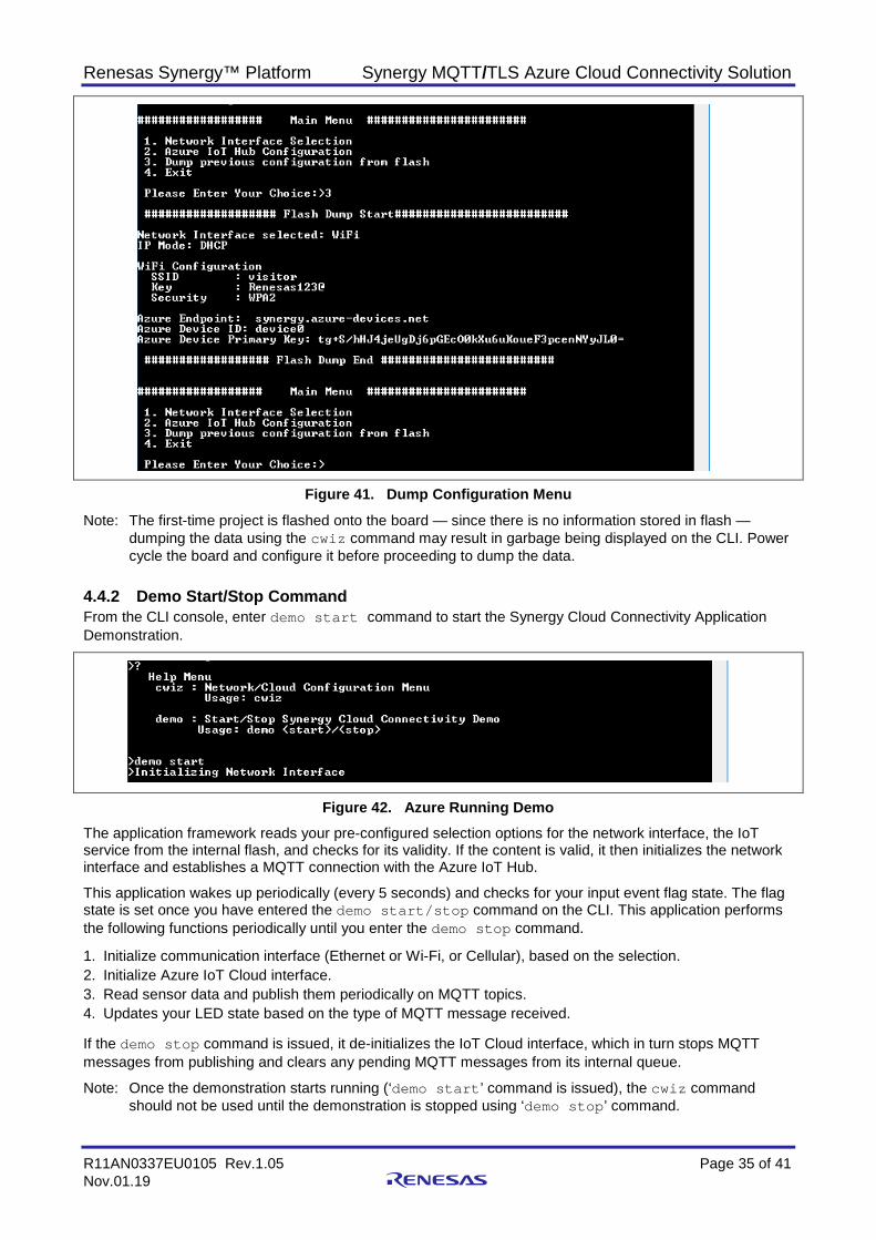
Figure 41. Dump Configuration Menu Note: The first-time project is flashed onto the board — since there is no information stored in flash —
dumping the data using the cwiz command may result in garbage being displayed on the CLI. Power cycle the board and configure it before proceeding to dump the data.
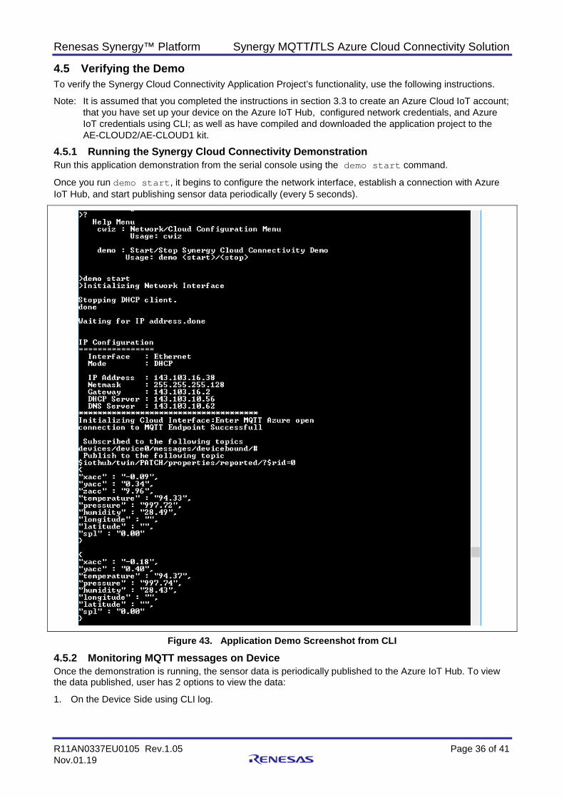
4.4.2 Demo Start/Stop Command From the CLI console, enter demo start command to start the Synergy Cloud Connectivity Application Demonstration.
Figure 42. Azure Running Demo The application framework reads your pre-configured selection options for the network interface, the IoT service from the internal flash, and checks for its validity. If the content is valid, it then initializes the network interface and establishes a MQTT connection with the Azure IoT Hub.
This application wakes up periodically (every 5 seconds) and checks for your input event flag state. The flag state is set once you have entered the demo start/stop command on the CLI. This application performs the following functions periodically until you enter the demo stop command.
1. Initialize communication interface (Ethernet or Wi-Fi, or Cellular), based on the selection. 2. Initialize Azure IoT Cloud interface. 3. Read sensor data and publish them periodically on MQTT topics. 4. Updates your LED state based on the type of MQTT message received. If the demo stop command is issued, it de-initializes the IoT Cloud interface, which in turn stops MQTT messages from publishing and clears any pending MQTT messages from its internal queue.
Note: Once the demonstration starts running (‘demo start’ command is issued), the cwiz command should not be used until the demonstration is stopped using ‘demo stop’ command.
Renesas Synergy™ Platform Synergy MQTT/TLS Azure Cloud Connectivity Solution
R11AN0337EU0105 Rev.1.05 Page 36 of 41 Nov.01.19
4.5 Verifying the Demo To verify the Synergy Cloud Connectivity Application Project’s functionality, use the following instructions.
Note: It is assumed that you completed the instructions in section 3.3 to create an Azure Cloud IoT account; that you have set up your device on the Azure IoT Hub, configured network credentials, and Azure IoT credentials using CLI; as well as have compiled and downloaded the application project to the AE-CLOUD2/AE-CLOUD1 kit.
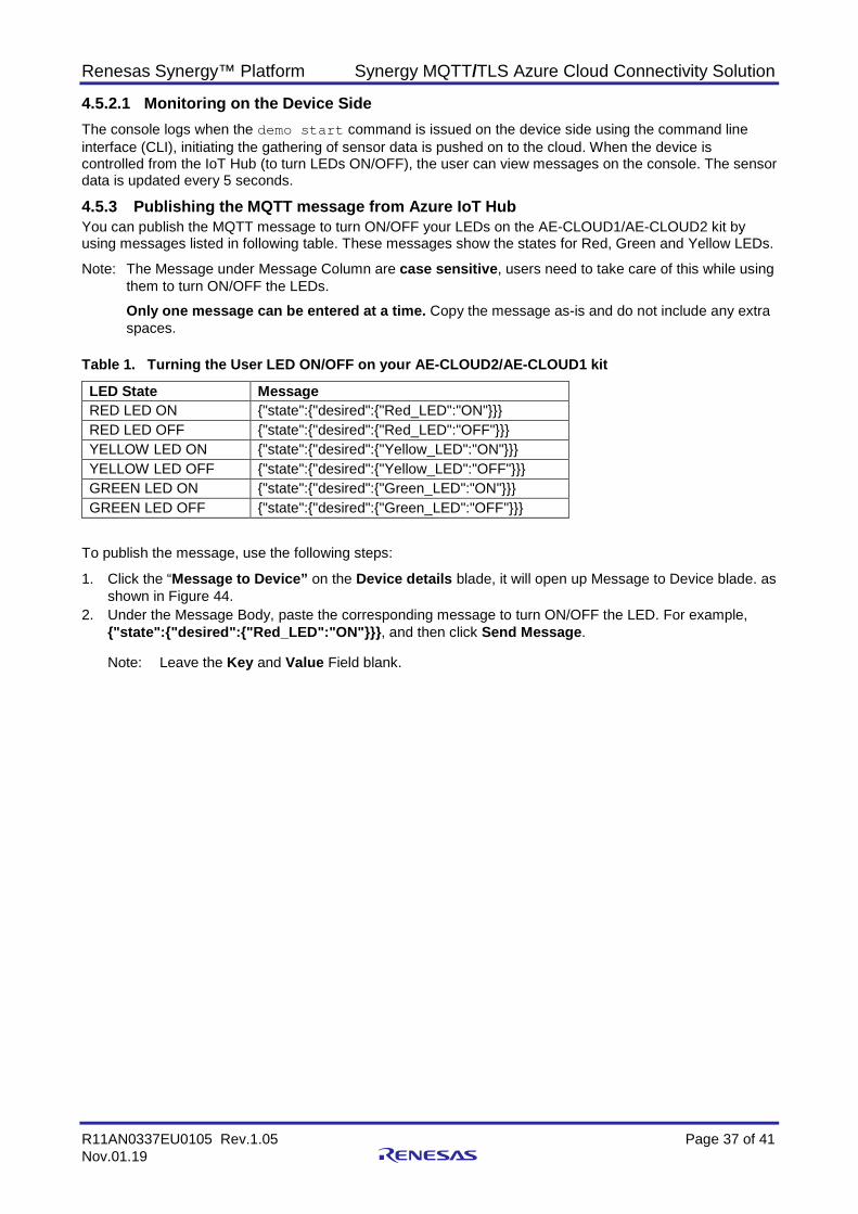
4.5.1 Running the Synergy Cloud Connectivity Demonstration Run this application demonstration from the serial console using the demo start command.
Once you run demo start, it begins to configure the network interface, establish a connection with Azure IoT Hub, and start publishing sensor data periodically (every 5 seconds).
Figure 43. Application Demo Screenshot from CLI
4.5.2 Monitoring MQTT messages on Device Once the demonstration is running, the sensor data is periodically published to the Azure IoT Hub. To view the data published, user has 2 options to view the data:
1. On the Device Side using CLI log.
Renesas Synergy™ Platform Synergy MQTT/TLS Azure Cloud Connectivity Solution
R11AN0337EU0105 Rev.1.05 Page 37 of 41 Nov.01.19
4.5.2.1 Monitoring on the Device Side The console logs when the demo start command is issued on the device side using the command line interface (CLI), initiating the gathering of sensor data is pushed on to the cloud. When the device is controlled from the IoT Hub (to turn LEDs ON/OFF), the user can view messages on the console. The sensor data is updated every 5 seconds.
4.5.3 Publishing the MQTT message from Azure IoT Hub You can publish the MQTT message to turn ON/OFF your LEDs on the AE-CLOUD1/AE-CLOUD2 kit by using messages listed in following table. These messages show the states for Red, Green and Yellow LEDs.
Note: The Message under Message Column are case sensitive, users need to take care of this while using them to turn ON/OFF the LEDs.
Only one message can be entered at a time. Copy the message as-is and do not include any extra spaces.
Table 1. Turning the User LED ON/OFF on your AE-CLOUD2/AE-CLOUD1 kit
LED State Message RED LED ON {"state":{"desired":{"Red_LED":"ON"}}} RED LED OFF {"state":{"desired":{"Red_LED":"OFF"}}} YELLOW LED ON {"state":{"desired":{"Yellow_LED":"ON"}}} YELLOW LED OFF {"state":{"desired":{"Yellow_LED":"OFF"}}} GREEN LED ON {"state":{"desired":{"Green_LED":"ON"}}} GREEN LED OFF {"state":{"desired":{"Green_LED":"OFF"}}}
To publish the message, use the following steps:
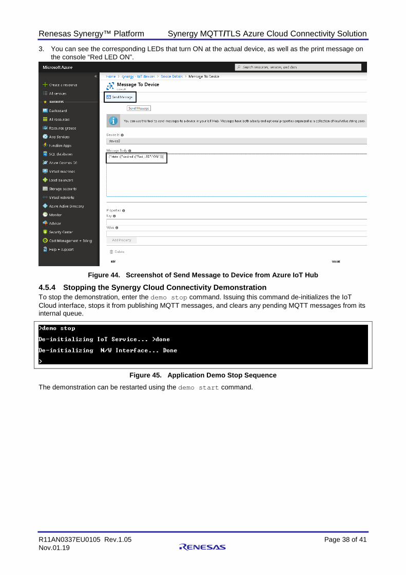
1. Click the “Message to Device” on the Device details blade, it will open up Message to Device blade. as shown in Figure 44.
2. Under the Message Body, paste the corresponding message to turn ON/OFF the LED. For example, {"state":{"desired":{"Red_LED":"ON"}}}, and then click Send Message.
Note: Leave the Key and Value Field blank.
Renesas Synergy™ Platform Synergy MQTT/TLS Azure Cloud Connectivity Solution
R11AN0337EU0105 Rev.1.05 Page 38 of 41 Nov.01.19
3. You can see the corresponding LEDs that turn ON at the actual device, as well as the print message on the console “Red LED ON”.
Figure 44. Screenshot of Send Message to Device from Azure IoT Hub
4.5.4 Stopping the Synergy Cloud Connectivity Demonstration To stop the demonstration, enter the demo stop command. Issuing this command de-initializes the IoT Cloud interface, stops it from publishing MQTT messages, and clears any pending MQTT messages from its internal queue.
Figure 45. Application Demo Stop Sequence The demonstration can be restarted using the demo start command.
Renesas Synergy™ Platform Synergy MQTT/TLS Azure Cloud Connectivity Solution
R11AN0337EU0105 Rev.1.05 Page 39 of 41 Nov.01.19
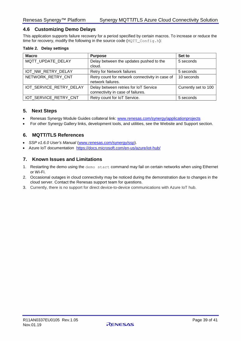
4.6 Customizing Demo Delays This application supports failure recovery for a period specified by certain macros. To increase or reduce the time for recovery, modify the following in the source code (MQTT_Config.h):
Table 2. Delay settings
Macro Purpose Set to MQTT_UPDATE_DELAY Delay between the updates pushed to the
cloud. 5 seconds
IOT_NW_RETRY_DELAY Retry for Network failures 5 seconds NETWORK_RETRY_CNT Retry count for network connectivity in case of
network failures. 10 seconds
IOT_SERVICE_RETRY_DELAY Delay between retries for IoT Service connectivity in case of failures.
Currently set to 100
IOT_SERVICE_RETRY_CNT Retry count for IoT Service. 5 seconds
5. Next Steps • Renesas Synergy Module Guides collateral link: www.renesas.com/synergy/applicationprojects • For other Synergy Gallery links, development tools, and utilities, see the Website and Support section.
6. MQTT/TLS References • SSP v1.6.0 User’s Manual (www.renesas.com/synergy/ssp). • Azure IoT documentation https://docs.microsoft.com/en-us/azure/iot-hub/
7. Known Issues and Limitations 1. Restarting the demo using the demo start command may fail on certain networks when using Ethernet
or Wi-Fi. 2. Occasional outages in cloud connectivity may be noticed during the demonstration due to changes in the
cloud server. Contact the Renesas support team for questions. 3. Currently, there is no support for direct device-to-device communications with Azure IoT hub.
Renesas Synergy™ Platform Synergy MQTT/TLS Azure Cloud Connectivity Solution
R11AN0337EU0105 Rev.1.05 Page 40 of 41 Nov.01.19
Website and Support Visit the following vanity URLs to learn about key elements of the Synergy Platform, download components and related documentation, and get support.
Synergy Software www.renesas.com/synergy/software Synergy Software Package www.renesas.com/synergy/ssp Software add-ons www.renesas.com/synergy/addons Software glossary www.renesas.com/synergy/softwareglossary
Development tools www.renesas.com/synergy/tools
Synergy Hardware www.renesas.com/synergy/hardware Microcontrollers www.renesas.com/synergy/mcus MCU glossary www.renesas.com/synergy/mcuglossary Parametric search www.renesas.com/synergy/parametric
Kits www.renesas.com/synergy/kits
Synergy Solutions Gallery www.renesas.com/synergy/solutionsgallery Partner projects www.renesas.com/synergy/partnerprojects
Application projects www.renesas.com/synergy/applicationprojects Self-service support resources:
Documentation www.renesas.com/synergy/docs Knowledgebase www.renesas.com/synergy/knowledgebase Forums www.renesas.com/synergy/forum Training www.renesas.com/synergy/training Videos www.renesas.com/synergy/videos Chat and web ticket www.renesas.com/synergy/resourcelibrary
Renesas Synergy™ Platform Synergy MQTT/TLS Azure Cloud Connectivity Solution
R11AN0337EU0105 Rev.1.05 Page 41 of 41 Nov.01.19
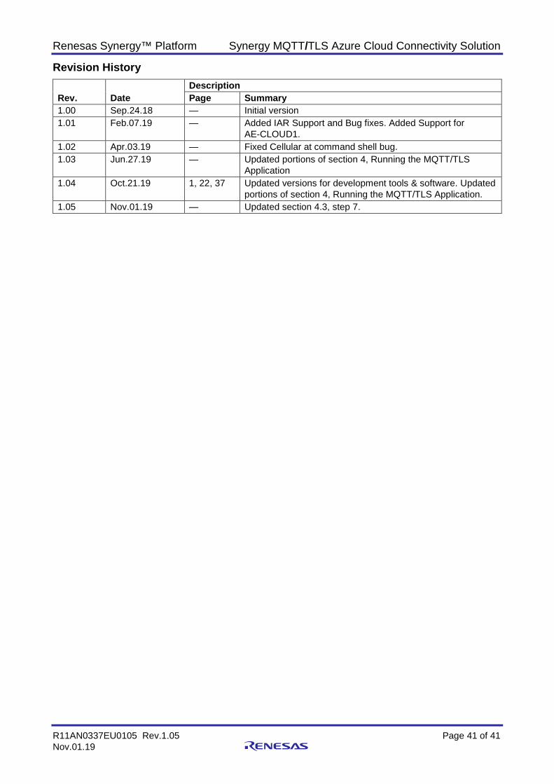
Revision History
Rev. Date Description Page Summary
1.00 Sep.24.18 — Initial version 1.01 Feb.07.19 — Added IAR Support and Bug fixes. Added Support for
AE-CLOUD1. 1.02 Apr.03.19 — Fixed Cellular at command shell bug. 1.03 Jun.27.19 — Updated portions of section 4, Running the MQTT/TLS
Application 1.04 Oct.21.19 1, 22, 37 Updated versions for development tools & software. Updated
portions of section 4, Running the MQTT/TLS Application. 1.05 Nov.01.19 — Updated section 4.3, step 7.
© 2019 Renesas Electronics Corporation. All rights reserved.
Notice 1. Descriptions of circuits, software and other related information in this document are provided only to illustrate the operation of semiconductor products
and application examples. You are fully responsible for the incorporation or any other use of the circuits, software, and information in the design of your product or system. Renesas Electronics disclaims any and all liability for any losses and damages incurred by you or third parties arising from the use of these circuits, software, or information.
2. Renesas Electronics hereby expressly disclaims any warranties against and liability for infringement or any other claims involving patents, copyrights, or other intellectual property rights of third parties, by or arising from the use of Renesas Electronics products or technical information described in this document, including but not limited to, the product data, drawings, charts, programs, algorithms, and application examples.
3. No license, express, implied or otherwise, is granted hereby under any patents, copyrights or other intellectual property rights of Renesas Electronics or others.
4. You shall not alter, modify, copy, or reverse engineer any Renesas Electronics product, whether in whole or in part. Renesas Electronics disclaims any and all liability for any losses or damages incurred by you or third parties arising from such alteration, modification, copying or reverse engineering.
5. Renesas Electronics products are classified according to the following two quality grades: “Standard” and “High Quality”. The intended applications for each Renesas Electronics product depends on the product’s quality grade, as indicated below. "Standard": Computers; office equipment; communications equipment; test and measurement equipment; audio and visual equipment; home
electronic appliances; machine tools; personal electronic equipment; industrial robots; etc. "High Quality": Transportation equipment (automobiles, trains, ships, etc.); traffic control (traffic lights); large-scale communication equipment; key
financial terminal systems; safety control equipment; etc. Unless expressly designated as a high reliability product or a product for harsh environments in a Renesas Electronics data sheet or other Renesas Electronics document, Renesas Electronics products are not intended or authorized for use in products or systems that may pose a direct threat to human life or bodily injury (artificial life support devices or systems; surgical implantations; etc.), or may cause serious property damage (space system; undersea repeaters; nuclear power control systems; aircraft control systems; key plant systems; military equipment; etc.). Renesas Electronics disclaims any and all liability for any damages or losses incurred by you or any third parties arising from the use of any Renesas Electronics product that is inconsistent with any Renesas Electronics data sheet, user’s manual or other Renesas Electronics document.
6. When using Renesas Electronics products, refer to the latest product information (data sheets, user’s manuals, application notes, “General Notes for Handling and Using Semiconductor Devices” in the reliability handbook, etc.), and ensure that usage conditions are within the ranges specified by Renesas Electronics with respect to maximum ratings, operating power supply voltage range, heat dissipation characteristics, installation, etc. Renesas Electronics disclaims any and all liability for any malfunctions, failure or accident arising out of the use of Renesas Electronics products outside of such specified ranges.
7. Although Renesas Electronics endeavors to improve the quality and reliability of Renesas Electronics products, semiconductor products have specific characteristics, such as the occurrence of failure at a certain rate and malfunctions under certain use conditions. Unless designated as a high reliability product or a product for harsh environments in a Renesas Electronics data sheet or other Renesas Electronics document, Renesas Electronics products are not subject to radiation resistance design. You are responsible for implementing safety measures to guard against the possibility of bodily injury, injury or damage caused by fire, and/or danger to the public in the event of a failure or malfunction of Renesas Electronics products, such as safety design for hardware and software, including but not limited to redundancy, fire control and malfunction prevention, appropriate treatment for aging degradation or any other appropriate measures. Because the evaluation of microcomputer software alone is very difficult and impractical, you are responsible for evaluating the safety of the final products or systems manufactured by you.
8. Please contact a Renesas Electronics sales office for details as to environmental matters such as the environmental compatibility of each Renesas Electronics product. You are responsible for carefully and sufficiently investigating applicable laws and regulations that regulate the inclusion or use of controlled substances, including without limitation, the EU RoHS Directive, and using Renesas Electronics products in compliance with all these applicable laws and regulations. Renesas Electronics disclaims any and all liability for damages or losses occurring as a result of your noncompliance with applicable laws and regulations.
9. Renesas Electronics products and technologies shall not be used for or incorporated into any products or systems whose manufacture, use, or sale is prohibited under any applicable domestic or foreign laws or regulations. You shall comply with any applicable export control laws and regulations promulgated and administered by the governments of any countries asserting jurisdiction over the parties or transactions.
10. It is the responsibility of the buyer or distributor of Renesas Electronics products, or any other party who distributes, disposes of, or otherwise sells or transfers the product to a third party, to notify such third party in advance of the contents and conditions set forth in this document.
11. This document shall not be reprinted, reproduced or duplicated in any form, in whole or in part, without prior written consent of Renesas Electronics. 12. Please contact a Renesas Electronics sales office if you have any questions regarding the information contained in this document or Renesas
Electronics products.
(Note1) “Renesas Electronics” as used in this document means Renesas Electronics Corporation and also includes its directly or indirectly controlled subsidiaries.
(Note2) “Renesas Electronics product(s)” means any product developed or manufactured by or for Renesas Electronics.
(Rev.4.0-1 November 2017)
Corporate Headquarters Contact information TOYOSU FORESIA, 3-2-24 Toyosu, Koto-ku, Tokyo 135-0061, Japan www.renesas.com
For further information on a product, technology, the most up-to-date version of a document, or your nearest sales office, please visit: www.renesas.com/contact/.
Trademarks Renesas and the Renesas logo are trademarks of Renesas Electronics Corporation. All trademarks and registered trademarks are the property of their respective owners.