
SynchroPhasor Roadmap - Western Electricity … · “Measurement-based” Voltage Stability...
9
SynchroPhasor Roadmap (Voltage Stability) Manu Parashar JSIS Meeting January 16 th , 2013
Transcript of SynchroPhasor Roadmap - Western Electricity … · “Measurement-based” Voltage Stability...

SynchroPhasor Roadmap
(Voltage Stability)
Manu Parashar
JSIS Meeting January 16th, 2013

Our Vision
Control Center -PDC
PMU
MEASUREMENT-BASED Analysis
(PhasorPoint)
Traditional
MODEL-BASED Analysis
(EMS)
SCADA & Alarms
WAMS
State Estimator
State Measurement
Other EMS Applications
New Applications
Small Signal Stability
Oscillation Monitoring
Transient & Voltage Stability
Stability Monitoring & Control
Island Management
Island Detection, Resynchronization, & Blackstart
Copyright ALSTOM Grid
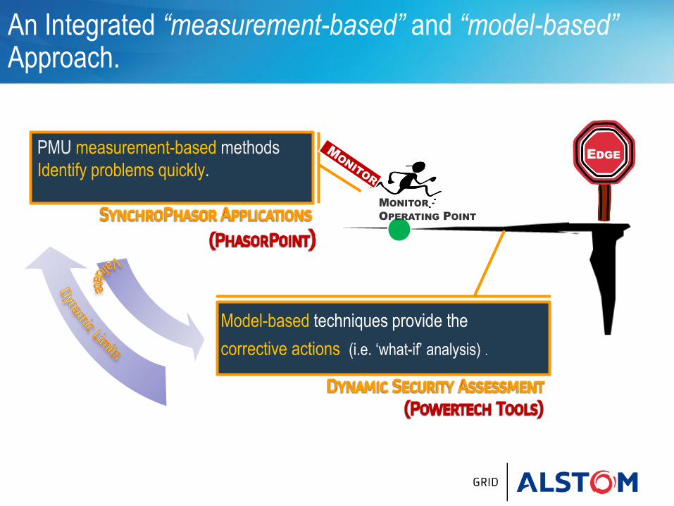
An Integrated “measurement-based” and “model-based” Approach.
PMU measurement-based methods
Identify problems quickly.
PREDICT & MITIGATE
EDGE
MONITOR
OPERATING POINT
Model-based techniques provide the
corrective actions (i.e. ‘what-if’ analysis) .

Wide Area Visualisation
RTUs
Online Stability Solution
PhasorPoint Workbench
Synchrophasor Framework
PMU & RTU
Aggregation Applications
e-terrabrowser
e-terravision
PMUs
Energy Management System
Dynamic Security Assessment

Hybrid Approach to Voltage Stability Assessment
“Measurement-based” Voltage Stability Indicators identify potential
stability problems, and include:
- Wide Area Voltage “Composite” Alarms: Identify low voltage violations simultaneously detected
over a broad area.
- Voltage Sensitivities: Assess voltage degradation (i.e. kV/100MW) with increased MW loading bases
on operating P-V locus.
- Reactive Reserves: Monitor available MVAR reserves in an area (i.e. all capacitors/reactors and units
within a sub-network of the power grid).
- Advanced Metrics (Voltage Instability Predictor, SVD): Other indicators based on key properties
associated with voltage collapse phenomenon (such as singularity or maximum loadability). (FUTURE)
“Model-based” Voltage Stability Analysis to evaluate:
- MW Margins to potential voltage violation or instability under most binding contingency.
- Weak elements within the network that will be impacted during a voltage instability.
- Critical contingencies responsible for the voltage stability violation.
- Corrective Actions to mitigate away from an impending instability.

Dynamic limit
On-Line Voltage Stability Assessment Integrated “measurement-based” and “model-based” analysis
MW Margins are computed in real-time
using “model-based” Voltage Stability
Assessment Tools (VSAT).
identify proximity to
voltage stability violation
Real-time P-V locus (and voltage sensitivities)
based on PMU measurements.
monitor current operating condition

Comprehensive Voltage Stability Alarms Linking WAMS “Wide-Area” Low Voltage Alarms to Operator Guides in EMS
WAMS Composite Alarms
WAMS indicate the simultaneous occurrence of Low Voltage over a broad region.
AND
Operator Guides in EMS
Reactive Reserve Monitoring in EMS Decision making:
Operator Guides (e.g. “Switch On
Capacitor Banks”).
Arm Special Protection Schemes
Reactive Reserve (MVAR) monitoring for user-defined areas in EMS.
Detect WHEN to Take Action...
and HOW to Respond!

Voltage Stability Assessment in e-terravision Voltage Contours, MW Margins, Weak Elements, Remedial Actions
Identify weak elements (i.e. regions most prone to voltage instability)
MW Transfer Margins
Control Recommendations

Regional Reactive Reserves Where are the Vars ?
Select region of interest to identify available VAR resources
Detailed summary of existing resources within chosen region