Synchronous Motor AC Drives
40
Unit V Synchronous Motor Drives
-
Upload
harshal-thakur -
Category
Documents
-
view
1.221 -
download
132
description
Synchonous motor AC drvies description and its working
Transcript of Synchronous Motor AC Drives

Unit V Synchronous Motor Drives
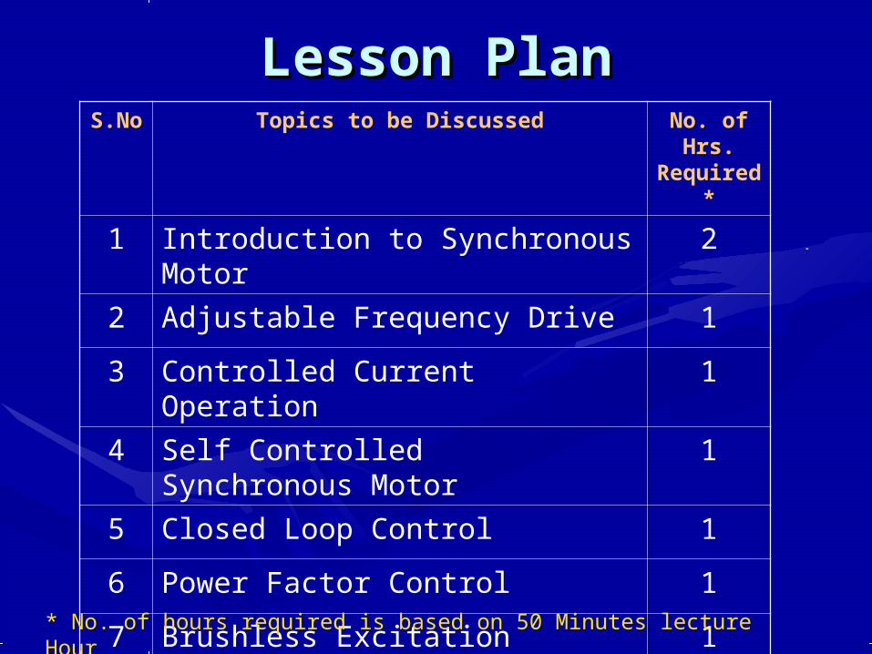
Lesson PlanLesson PlanS.No
Topics to be Discussed No. of Hrs.
Required*
1 Introduction to Synchronous Motor
2
2 Adjustable Frequency Drive 1
3 Controlled Current Operation 1
4 Self Controlled Synchronous Motor
1
5 Closed Loop Control 1
6 Power Factor Control 1
7 Brushless Excitation 1
8 Tutorial 2* No. of hours required is based on 50 Minutes lecture Hour
IntroductionIntroduction
SynchronousSynchronous - Occurring or existing at the same - Occurring or existing at the same time time
or having the same period or phase.or having the same period or phase.
Synchronous Speed:Synchronous Speed: N Nss=120f/P=120f/P
Synchronous Motor Consists of and Stator Rotor Synchronous Motor Consists of and Stator Rotor Consists of a 3 Phase Winding Stator.Consists of a 3 Phase Winding Stator.
..

Classification of Classification of Synchronous MotorSynchronous Motor
☼ Wound field Synchronous MotorWound field Synchronous Motor☼ Permanent Magnet Synchronous MotorPermanent Magnet Synchronous Motor☼ Reluctance Synchronous MotorReluctance Synchronous Motor
Wound Field Synchronous Wound Field Synchronous MotorMotor
The Rotor field flux can be produced by The Rotor field flux can be produced by a DC excited field winding.a DC excited field winding.
The rotating field system is preferred, The rotating field system is preferred, because, the DC excitation current is because, the DC excitation current is relatively small and can be supplied by relatively small and can be supplied by only two slip rings.only two slip rings.
Field Excitation can be varied, greater Field Excitation can be varied, greater flexibility is available.flexibility is available.
This type of construction is preferred This type of construction is preferred for very high power rating(1500MW).for very high power rating(1500MW).

Round Rotor Synchronous Synchronous MachinesMachines
Round Rotor Machine (Non Salient pole)
The stator is a ring shaped laminated iron-core with slots.
Three phase windings are placed in the stator slots.
Round laminated iron rotor core with slots.
A single winding is placed in the slots. DC current is supplied through slip rings.
Concept (two poles)
N S
A
-B
+
A
+C
+
C
-
B
-
A
B
CStator with laminated iron-core
Slots withwinding
Rotor with DCwinding

Salient Rotor Synchronous Synchronous MachinesMachines
Salient Rotor Machine The stator has a laminated iron-
core with slots and three phase windings placed in the slots.
The rotor has salient poles excited by DC current.
DC current is supplied to the rotor through slip-rings and brushes.
The number of poles varies between 2 - 128.
Concept (two poles)Concept (two poles)
N
S
A+
B+
C+B-
A-
C-

Permanent Magnet (PM) Permanent Magnet (PM) Synchronous Motor Synchronous Motor
The rotor field flux can be produced by The rotor field flux can be produced by permanent magnets rather than Electromagnetspermanent magnets rather than Electromagnets
Various Fe, Ni, Co based alloys can be used Various Fe, Ni, Co based alloys can be used The permanent magnets can be located either at The permanent magnets can be located either at
the surface of the rotor or within the body of the the surface of the rotor or within the body of the rotor.rotor.
There is no need for brushes hence, this type of There is no need for brushes hence, this type of motor is also called as brushless Synchronous motor is also called as brushless Synchronous Motor.Motor.
Available only at Low Power ratings.Available only at Low Power ratings. Field excitation cannot be varied.Field excitation cannot be varied.
Reluctance Synchronous Reluctance Synchronous MotorMotor
If a synchronously rotating stator field If a synchronously rotating stator field is established by means of a is established by means of a conventional polyphase winding conventional polyphase winding excited by a balanced Polyphase excited by a balanced Polyphase AC supply, then the rotor runs in exact AC supply, then the rotor runs in exact synchronism with this field poles seek synchronism with this field poles seek to maintain the Minimum reluctance to maintain the Minimum reluctance position with respect to the stator flux.position with respect to the stator flux.
Rotor may be a Salient pole or Non Rotor may be a Salient pole or Non salient pole type.salient pole type.

C.S. View of Synchronous C.S. View of Synchronous MotorMotor
Stator Rotor
Connections
Bearing
Stator windingRotor winding
Housing ,cooling ducts
Shaft

Operating Principle
Supply Current Generated Flux
Total flux is the vector sum of the three components:
(t) = a(t) + b(t) + c(t)
The next figure shows the three components at t = 300 and max = 1
The resultant flux amplitude is 1.5 times the flux produced by each phase

>> Operating Principle Balanced 3 phase supply currents establish a Balanced 3 phase supply currents establish a
component flux wave in the air gap, which has component flux wave in the air gap, which has an approximately sinusoidal spatial an approximately sinusoidal spatial distribution with a constant amplitude and distribution with a constant amplitude and which rotates at synchronous speed.which rotates at synchronous speed.
If the rotor rotates at synchronous speed, the If the rotor rotates at synchronous speed, the magnetic fields of stator and rotor are magnetic fields of stator and rotor are stationary relative to one another, and a stationary relative to one another, and a steady state torque is developed because of steady state torque is developed because of the tendency of the two magnetic fields to the tendency of the two magnetic fields to align their axes (Constant Speed).align their axes (Constant Speed).

Starting of Synchronous Starting of Synchronous RotorRotor
The synchronous motor has no The synchronous motor has no starting torque, it must be brought starting torque, it must be brought up to synchronous speed by up to synchronous speed by induction motor action or by an induction motor action or by an auxiliary motor.auxiliary motor.

Pull-in and Pull-out Pull-in and Pull-out torquetorque
Pull-in Torque:Pull-in Torque:
The maximum load torque that the The maximum load torque that the motor can pull into synchronism motor can pull into synchronism with a specified load inertia.with a specified load inertia.
Pull-out Torque:Pull-out Torque:
Load torque required to pull the Load torque required to pull the rotor out of synchronism.rotor out of synchronism.

Synchronous Motor Drive With PWM Synchronous Motor Drive With PWM InverterInverter
The AC voltage of the supply is rectified.
The DC link filters the harmonics and produces smooth DC.
The PWM inverter produces a variable frequency and voltage sine wave that drives the motor.
The frequency regulates the motor speed.
The voltage to frequency ratio is kept constant to avoid saturation at low frequencies.
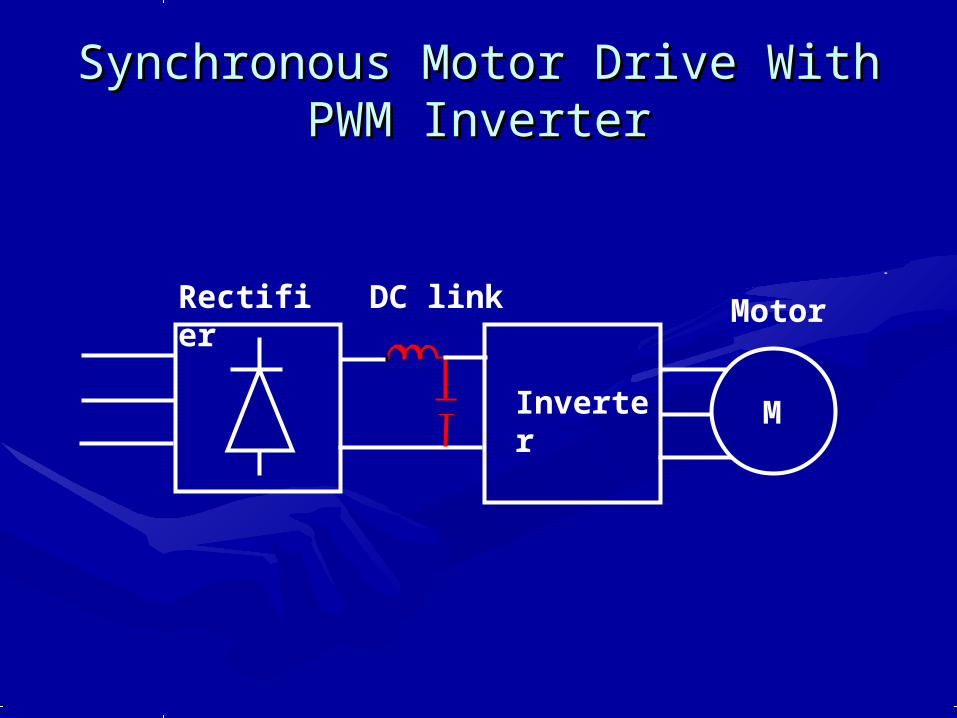
Synchronous Motor Drive With PWM Synchronous Motor Drive With PWM InverterInverter
Rectifier
Inverter
DC link Motor
M

Adjustable Frequency Adjustable Frequency OperationOperation
Motor Speed is precisely related to the Motor Speed is precisely related to the supply frequency.supply frequency.
Synchronous motor drive can provide Synchronous motor drive can provide accurate speed control, particularly when accurate speed control, particularly when adjustable frequency supply is available.adjustable frequency supply is available.
Harmonic effects in the motor are usually Harmonic effects in the motor are usually negligible. negligible.
Harmonics results extra heating in motor.Harmonics results extra heating in motor.
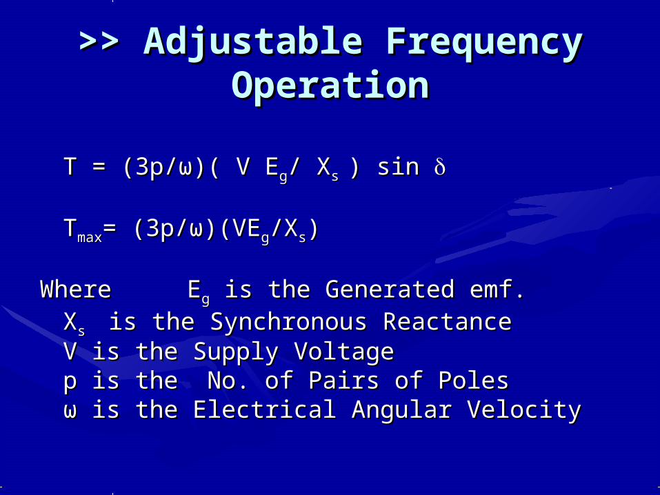
>> Adjustable Frequency >> Adjustable Frequency OperationOperation
T = (3p/T = (3p/ωω)( V E)( V Egg/ X/ Xs s ) sin ) sin
TTmaxmax= (3p/= (3p/ωω)(VE)(VEgg/X/Xss))
Where Where EEgg is the Generated emf. is the Generated emf.XXss is the Synchronous Reactanceis the Synchronous ReactanceV is the Supply VoltageV is the Supply Voltagep is the No. of Pairs of Polesp is the No. of Pairs of Polesωω is the Electrical Angular Velocity is the Electrical Angular Velocity

Torque Vs Load AngleTorque Vs Load Angle

>> Adjustable Frequency >> Adjustable Frequency OperationOperation At base speed – Rated voltage and frequency are At base speed – Rated voltage and frequency are
applied.applied.
Supply Frequency is increased to give higher Supply Frequency is increased to give higher speeds with a constant motor voltage.speeds with a constant motor voltage.
For constant field excitation the term EFor constant field excitation the term Eff/X/Xss is is constant. Above the base speed , the pull out constant. Above the base speed , the pull out torque falls off inversely with speed to give the torque falls off inversely with speed to give the usual Constant HP region of operation.usual Constant HP region of operation.
With a constant V/f supply, armature resistance With a constant V/f supply, armature resistance plays a important role at lower frequencies plays a important role at lower frequencies because the resistive voltage drop is comparable because the resistive voltage drop is comparable in magnitude to the terminal voltage.in magnitude to the terminal voltage.

Controlled Current Controlled Current OperationOperation
The synchronous motor is fed from a The synchronous motor is fed from a variable stator current converter with the variable stator current converter with the supply voltage adjusting itself automatically.supply voltage adjusting itself automatically.
The torque can be expressed in terms of The torque can be expressed in terms of stator current rather than stator voltage.stator current rather than stator voltage.
Total Input Power Total Input Power P = 3 EP = 3 Egg I Iaa cos cosφφ
TorqueTorque T = 3 p LT = 3 p Lm m IIff11 I Ia a sin sin
T = K T = K ff I Ia a sin sin
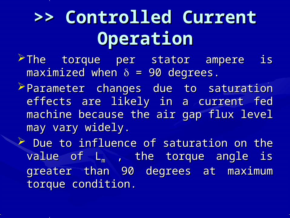
>> Controlled Current >> Controlled Current OperationOperation
The torque per stator ampere is The torque per stator ampere is maximized when maximized when = 90 degrees. = 90 degrees.
Parameter changes due to saturation Parameter changes due to saturation effects are likely in a current fed machine effects are likely in a current fed machine because the air gap flux level may vary because the air gap flux level may vary widely.widely.
Due to influence of saturation on the Due to influence of saturation on the value of Lvalue of Lmm , the torque angle is greater , the torque angle is greater than 90 degrees at maximum torque than 90 degrees at maximum torque condition.condition.

Self Controlled Self Controlled Synchronous MotorSynchronous Motor
A Machine is said A Machine is said to be self to be self controlled if it controlled if it gets the operating gets the operating frequency from frequency from the inverter the inverter whose Thyristors whose Thyristors are fired from a are fired from a rotor position rotor position sensing unit.sensing unit.
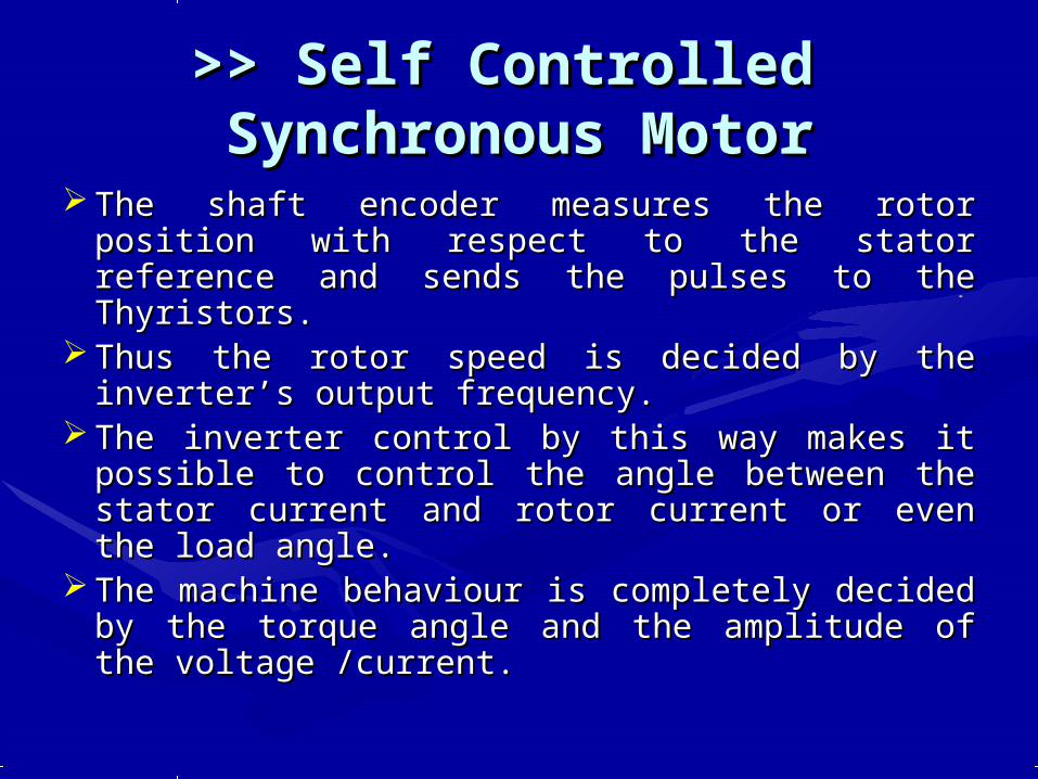
>> Self Controlled >> Self Controlled Synchronous MotorSynchronous Motor
The shaft encoder measures the rotor position The shaft encoder measures the rotor position with respect to the stator reference and sends with respect to the stator reference and sends the pulses to the Thyristors.the pulses to the Thyristors.
Thus the rotor speed is decided by the Thus the rotor speed is decided by the inverter’s output frequency.inverter’s output frequency.
The inverter control by this way makes it The inverter control by this way makes it possible to control the angle between the possible to control the angle between the stator current and rotor current or even the stator current and rotor current or even the load angle.load angle.
The machine behaviour is completely decided The machine behaviour is completely decided by the torque angle and the amplitude of the by the torque angle and the amplitude of the voltage /current.voltage /current.
>> Self Controlled >> Self Controlled Synchronous MotorSynchronous Motor
The self controlled motor doesn't fall The self controlled motor doesn't fall out of step, does not have oscillatory out of step, does not have oscillatory behaviour and has better stability behaviour and has better stability characteristics.characteristics.
Self Controlled Synchronous Motor Self Controlled Synchronous Motor can be operated at varying power can be operated at varying power factors by changing the excitation.factors by changing the excitation.
Over Excited Motor – Leading power Over Excited Motor – Leading power factorfactor

>> Self Controlled >> Self Controlled Synchronous MotorSynchronous Motor
Leading power factor operation Leading power factor operation provides necessary voltage required for provides necessary voltage required for commutation of Thyristors.commutation of Thyristors.
This eliminates the commutating circuit This eliminates the commutating circuit elements.elements.
The drive is very simple and economical The drive is very simple and economical with better utilization of Thyristors and with better utilization of Thyristors and good dynamic behaviour.good dynamic behaviour.
The inverter is said to be machine The inverter is said to be machine commutated.commutated.

>> Self Controlled >> Self Controlled Synchronous MotorSynchronous Motor
Disadvantage:Disadvantage:Inability to provide commutation at Inability to provide commutation at
very low speeds. As the machine voltage very low speeds. As the machine voltage is not of sufficient magnitudes especially is not of sufficient magnitudes especially at starting of motors from zero speed.at starting of motors from zero speed.
A force commutated circuit can be used A force commutated circuit can be used to bring the machine to a minimum to bring the machine to a minimum speed( 10% of the rated speed) beyond speed( 10% of the rated speed) beyond which machine voltages can be used for which machine voltages can be used for commutation purpose.commutation purpose.

>> Self Controlled >> Self Controlled Synchronous MotorSynchronous Motor
Self controlled synchronous motor Self controlled synchronous motor finds application where the DC finds application where the DC motors are objectionable because of motors are objectionable because of mechanical commutator which limits mechanical commutator which limits the speed range and power output.the speed range and power output.
It replaces the Induction motor It replaces the Induction motor because no forced commutation is because no forced commutation is required.required.
This reduces the cost of inverter.This reduces the cost of inverter.

Closed Loop ControlClosed Loop ControlIn wound field rotor synchronous In wound field rotor synchronous
motor the field current is adjusted motor the field current is adjusted such that the motor operates with such that the motor operates with the air-gap flux equal to the the air-gap flux equal to the maximum permissible value for all maximum permissible value for all loads and speeds.loads and speeds.
Air-gap flux control avoids the Air-gap flux control avoids the extremes of magnetic saturation or extremes of magnetic saturation or underutilization of the iron of the underutilization of the iron of the machine.machine.

>> Closed Loop Control>> Closed Loop Control If the armature current, field current, and torque If the armature current, field current, and torque
angle are controllable, the power factor at the angle are controllable, the power factor at the motor terminals can be controlled.motor terminals can be controlled.
Leading Power factor operation –load commutation Leading Power factor operation –load commutation of inverter.of inverter.
UPF can be achieved by forced commutated UPF can be achieved by forced commutated inverter.inverter.
Commutation failure will occur if the margin angle Commutation failure will occur if the margin angle becomes so small that the turn off time provided is becomes so small that the turn off time provided is less than the Thyristor recovery time.less than the Thyristor recovery time.

Closed Loop Power factor Closed Loop Power factor ControlControl

Closed Loop Power factor Closed Loop Power factor ControlControl
Shaft Positioning is used in conjunction Shaft Positioning is used in conjunction with Voltage and Current sensing to allow with Voltage and Current sensing to allow closed loop control of Power factor.closed loop control of Power factor.
The phase relationship between motor The phase relationship between motor voltage and current is automatically voltage and current is automatically varied so that the motor power factor is varied so that the motor power factor is maintained constant at a command value.maintained constant at a command value.
The resultant air gap flux is independently The resultant air gap flux is independently regulated by closed loop control.regulated by closed loop control.
Actual air gap flux is compared with Actual air gap flux is compared with desired value and the error signal is used desired value and the error signal is used to drive the field current controller.to drive the field current controller.

Brushless ExcitationBrushless ExcitationElectronically commutated permanent Electronically commutated permanent
magnet synchronous motors are used magnet synchronous motors are used in high performance tools and robotics.in high performance tools and robotics.
In a permanent magnet synchronous In a permanent magnet synchronous motor, the field excitation cannot be motor, the field excitation cannot be controlled , and the excitation emf or controlled , and the excitation emf or back emf, keeps increasing with speed.back emf, keeps increasing with speed.
Above the base speed the motor back Above the base speed the motor back emf is excessively large.emf is excessively large.

>> Brushless Excitation>> Brushless Excitation
Motor Copper loss is high due to large Motor Copper loss is high due to large stator currents.stator currents.
A brushless resolver or digital encoder A brushless resolver or digital encoder is used as a rotor position sensor is used as a rotor position sensor providing the precise information providing the precise information needed to generate reference current needed to generate reference current waveforms which are sinusoidal waveforms which are sinusoidal functions of angular position.functions of angular position.

Closed Loop Control of PM Closed Loop Control of PM Synchronous MotorSynchronous Motor

Closed Loop Control of PM Closed Loop Control of PM Synchronous MotorSynchronous Motor
Set speed and actual speed are compared , and Set speed and actual speed are compared , and the speed error defines the set current or the speed error defines the set current or commanded torque.commanded torque.
Brushless resolver give s the absolute rotor Brushless resolver give s the absolute rotor position information and the torque angle is position information and the torque angle is dynamically varied as a function of rotor speed dynamically varied as a function of rotor speed and torque to give optimum drive performance.and torque to give optimum drive performance.
The Multiplying DAC (MDAC) output voltage is The Multiplying DAC (MDAC) output voltage is also proportional in magnitude to an also proportional in magnitude to an independent reference voltage which is the independent reference voltage which is the compensated speed error or set current signal.compensated speed error or set current signal.

Closed Loop Control of PM Closed Loop Control of PM Synchronous MotorSynchronous Motor
All the three currents are controlled All the three currents are controlled in amplitude by the common speed in amplitude by the common speed error voltage.error voltage.
Each phase currents are compared Each phase currents are compared by independent current loops with by independent current loops with the set current and error signal is the set current and error signal is fed to the PWM generation unit.fed to the PWM generation unit.

ReferencesReferences
Dubey G.K., ‘Power Semiconductor Dubey G.K., ‘Power Semiconductor Drives’ Prentice Hall International Drives’ Prentice Hall International 1989.1989.
Murphy J.M.D., and Turnbull F.G., Murphy J.M.D., and Turnbull F.G., ‘Thyristor Control of AC Motors’, ‘Thyristor Control of AC Motors’, Permagon Press, 1988.Permagon Press, 1988.
URLURLwww.eas.asu.edu/~karady/360_stuff/www.eas.asu.edu/~karady/360_stuff/Lectures/2Lectures/2

DiscussionDiscussion

Thank YouThank You