SY0.5 Drum Synthesizer User GuideSY0.5 Drum Synthesizer User Guide Mode Increment Sweep Speed LFO...
2
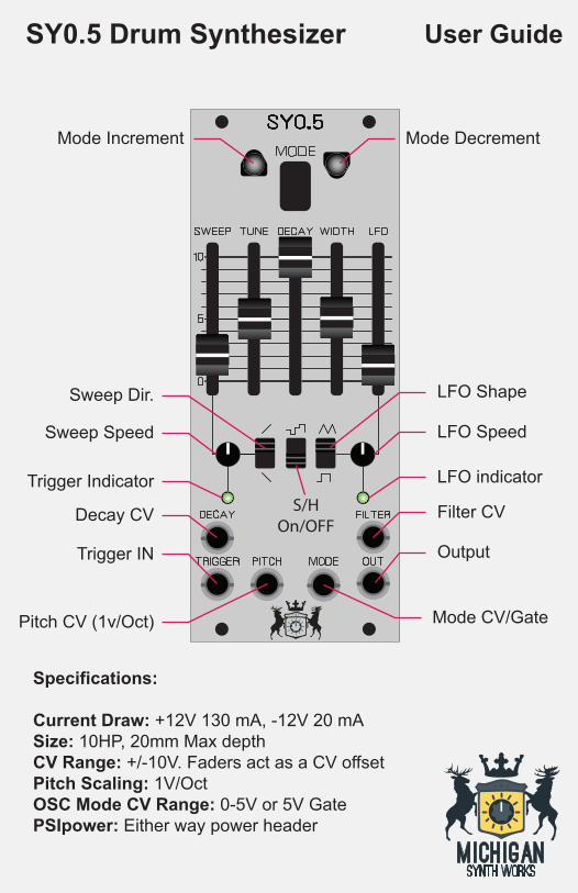
SY0.5 Drum Synthesizer User Guide Mode Increment Sweep Speed LFO Speed Trigger Indicator LFO indicator Filter CV Output Decay CV Trigger IN Mode CV/Gate Pitch CV (1v/Oct) Sweep Dir. LFO Shape S/H On/OFF Mode Decrement Specifications: Current Draw: +12V 130 mA, -12V 20 mA Size: 10HP, 20mm Max depth CV Range: +/-10V. Faders act as a CV offset Pitch Scaling: 1V/Oct OSC Mode CV Range: 0-5V or 5V Gate PSIpower: Either way power header
Transcript of SY0.5 Drum Synthesizer User GuideSY0.5 Drum Synthesizer User Guide Mode Increment Sweep Speed LFO...
SY0.5 Drum Synthesizer User Guide
Mode Increment
Sweep Speed LFO Speed
Trigger Indicator LFO indicator
Filter CV
Output
Decay CV
Trigger IN
Mode CV/GatePitch CV (1v/Oct)
Sweep Dir. LFO Shape
S/HOn/OFF
Mode Decrement
Specifications:
Current Draw: +12V 130 mA, -12V 20 mA Size: 10HP, 20mm Max depthCV Range: +/-10V. Faders act as a CV offset Pitch Scaling: 1V/OctOSC Mode CV Range: 0-5V or 5V GatePSIpower: Either way power header

0SC MODE (from the Pearl Manual)
The wave frequency, variation range, and noise of the 2 osciIIIators are pre-set.
A: One oscillator sound, at this position the regular drum synthesizer sweep can be effected.
B. Sound of one oscillator adjusting the other osciIIator frequency; produces a metallic sound.
C. Sound of a mix of two oscillator outputs; sound is similar to that of a vibraphone.
D. Sound of mix of two oscillator outputs; produces a low to high sweep and is done by hitting pad softly or hard; there is no connection to SWEEP SPEED and SWEEP RANGE
E. Sound of one oscillator adjusting the other oscillator frequency with a mix of noise; produces a sound similar to hitting thin metal.
F. Sound of only noise.
CONTROLS
TUNE: Sound of 2 oscillator frequencies and filter cutoff frequency adjusted; this makes tuning possible.
DECAY: Adjusts the sustain of individual notes.
WIDTH: Adjusting of the filter cutoff frequency range, when the range is wide, the wave frequency starts from high and gradually becomes low.
SWEEP SECTION
SPEED: Adjusts the rate of transition from the original pitch sounded when a drum is struck to a final pitch determined by the SWEEP section DEPTH control.
SWEEP FADER: Controls the final pitch heard of each note sounded when the SWEEP section movement switch is UP or DOWN. The DEPTH control tracks the TUNE control. Setting the fader to 0 turns off the sweep modulation.
DIRECTION: Controls direction of pitch movement both UP and DOWN.
LOW FREQUENCY OSCILILATOR (LFO) SECTION
LFO SPEED: Adjusts the speed of the low frequency oscillator to enable vibrato to be added to the basic sound selected by the SIGNAL SOURCE and SWEEP sections
.
LFO FADER: Controls the amount of pitch movement, at the speed determined by the LFO section. Setting the fader to 0 turns off the LFO modulation.
LFO SHAPE: This switch determines the wave shape employed by the LFO section. A square wave results in abrupt pitch changes and notice-able pitch at upper and lower extremes. A triangle wave results in almost continuous movement and little time spent at the pitch extremes.
S/H (SAMPLE AND HOLD): This switch adds a sample and hold output signal to the main output. S/H speed is set by the LFO section SPEED control. S/H will operate even if LFO modulation is OFF. When you switch on S/H, the tune will be automatically changed with each hit.
INPUTS
DECAY CV: -10V to 10V. Acts as an offset to the DECAY slider.
Trigger In: This triggers the VCA of the device, it is a DYNAMIC input so it will respond differently to various level pulses. The sensitivity can be adjusted with the sense trimmer on the back. The circuit is unchanged from the original device so drum triggers can be attached to this input.
PITCH CV: -10V to 10V, 1V/Oct scaling. Acts as an offset to the TUNE slider
MODE: This input changes the OSC mode type and has two types of operations: CV Control where the OSC mode is selected by sending a CV 0-5V and Gate Advance where a gate on this input advances the OSC mode to the next mode whenever a gate or trigger is received (5V). The direction of the change in Gate Advance mode is determined by the direction of the last manual OSC Mode change using the OSC mode buttons. To switch between these two functions, simply long press BOTH buttons for 3 seconds.
OUTPUT: Audio output at Eurorack levels
FILTER CV: -10V to 10V. Filter cutoff frequency as an offset to the WIDTH slider
www.MichiganSynthWorks.comDecember 2018 [email protected]