
SW_Platform
104
SOFTWARE PLATFORM SPECIFICATION Document #: SW_Platform.doc Equipment: Machines based on Rockwell or Siemens systems. Project #: 100xxx Customer: EEDpt File: ...\SW_Platform.doc Révision: 1.13 Page: 1 / 104 SOFTWARE PLATFORM SPECIFICATION Supplier Komax Medtech Allée du Quartz, 12 2301 La Chaux de Fonds Switzerland Equipment Machines based on Rockwell or Siemens systems.
-
Upload
pourchet-jean-claude -
Category
Documents
-
view
10 -
download
1
Transcript of SW_Platform

SOFTWARE PLATFORM SPECIFICATION Document #: SW_Platform.doc
Equipment: Machines based on Rockwell or Siemens systems. Project #: 100xxx Customer: EEDpt
File: ...\SW_Platform.doc Révision: 1.13 Page: 1 / 104
SOFTWARE
PLATFORM SPECIFICATION
Supplier
Komax Medtech
Allée du Quartz, 12
2301 La Chaux de Fonds
Switzerland
Equipment
Machines based on Rockwell or Siemens systems.

SOFTWARE PLATFORM SPECIFICATION Document #: SW_Platform.doc
Equipment: Machines based on Rockwell or Siemens systems. Project #: 100xxx Customer: EEDpt
File: ...\SW_Platform.doc Révision: 1.13 Page: 2 / 104
Table of Contents 1. Introduction ..................................................................................................................................................... 9
1.1. Account of modifications ......................................................................................................................................... 9 1.2. Signatures ............................................................................................................................................................... 10 1.3. Reference documents ............................................................................................................................................. 11
1.3.1. Standards & References ........................................................................................................................................................ 11 1.3.2. Working Documents.............................................................................................................................................................. 11
2. Executive Summary ....................................................................................................................................... 12 2.1. Preliminary ............................................................................................................................................................. 12 2.2. Objective ................................................................................................................................................................. 12
2.2.1. One Goal ............................................................................................................................................................................... 12 2.2.2. Three Needs .......................................................................................................................................................................... 12
2.2.2.1. Standard & References (State of the Art) ............................................................................................................................................. 12 2.2.2.2. Good Automation Practices .................................................................................................................................................................. 12 2.2.2.3. Rapid Application Development .......................................................................................................................................................... 12
2.2.3. Five E2ASY Paths ................................................................................................................................................................. 12 2.2.3.1. Emulation for early de-risking + Fail Safe for auto-recovery ............................................................................................................... 12 2.2.3.2. Effectiveness for ahead diagnostics ...................................................................................................................................................... 12 2.2.3.3. Agility for last minute changes ............................................................................................................................................................. 12 2.2.3.4. Simplicity always in mind .................................................................................................................................................................... 12 2.2.3.5. Yes we comply ..................................................................................................................................................................................... 12
2.2.4. Key points Summary ............................................................................................................................................................. 13 2.2.4.1. Three major needs ................................................................................................................................................................................ 13 2.2.4.2. 5 outstanding features........................................................................................................................................................................... 13 2.2.4.3. 4 elementary managers manage the following features ........................................................................................................................ 13 2.2.4.4. 4 elementary actuators incorporate the following features ................................................................................................................... 13 2.2.4.5. In addition ............................................................................................................................................................................................ 13
2.3. Document Summary .............................................................................................................................................. 14 2.3.1. Gamp Guide Lines ................................................................................................................................................................ 14 2.3.2. Design Guide Lines ............................................................................................................................................................... 14 2.3.3. Hardware Interfaces .............................................................................................................................................................. 14 2.3.4. Admin Details ....................................................................................................................................................................... 14 2.3.5. Machine Details..................................................................................................................................................................... 14 2.3.6. Asynchronous Stations Details .............................................................................................................................................. 14 2.3.7. Synchronous Stations Details ................................................................................................................................................ 14 2.3.8. Actuators Details ................................................................................................................................................................... 14
3. Gamp Guide Lines ......................................................................................................................................... 15 3.1. V Life Cycle ............................................................................................................................................................ 15 3.2. Tests Overview ....................................................................................................................................................... 16
3.2.1. Objectives .............................................................................................................................................................................. 16 3.2.2. Modules ................................................................................................................................................................................. 16 3.2.3. Box ........................................................................................................................................................................................ 16
3.2.3.1. Black .................................................................................................................................................................................................... 16 3.2.3.2. White .................................................................................................................................................................................................... 16
3.2.4. Komax Rules ......................................................................................................................................................................... 17 3.2.5. Software Architecture ............................................................................................................................................................ 17 3.2.6. Architecture & Scope ............................................................................................................................................................ 17
3.2.6.1. "Out of scope" ...................................................................................................................................................................................... 17 3.2.6.2. "In the scope" ....................................................................................................................................................................................... 17 3.2.6.3. Risky Station ........................................................................................................................................................................................ 17 3.2.6.4. Black Box Scope .................................................................................................................................................................................. 17 3.2.6.5. White Box Scope.................................................................................................................................................................................. 17
3.3. Tests Procedures .................................................................................................................................................... 18 3.3.1. Black Tests ............................................................................................................................................................................ 18
3.3.1.1. "State transition" .................................................................................................................................................................................. 18 3.3.1.2. Imperative vs Sequencing Logic .......................................................................................................................................................... 18
3.3.2. White Tests ............................................................................................................................................................................ 19 3.3.2.1. "Data Flow".......................................................................................................................................................................................... 19 3.3.2.2. "Branch/Decision" ................................................................................................................................................................................ 19 3.3.2.3. Standard Model .................................................................................................................................................................................... 19
3.4. Software Plan ......................................................................................................................................................... 20 3.4.1. Design ................................................................................................................................................................................... 20 3.4.2. Code ...................................................................................................................................................................................... 20 3.4.3. Setup...................................................................................................................................................................................... 20 3.4.4. Debug .................................................................................................................................................................................... 20 3.4.5. Test-Up .................................................................................................................................................................................. 20
3.5. Categories ............................................................................................................................................................... 21
SOFTWARE PLATFORM SPECIFICATION Document #: SW_Platform.doc
Equipment: Machines based on Rockwell or Siemens systems. Project #: 100xxx Customer: EEDpt
File: ...\SW_Platform.doc Révision: 1.13 Page: 3 / 104
3.5.1. Operational system ................................................................................................................................................................ 21 3.5.2. Firmware ............................................................................................................................................................................... 21 3.5.3. Standard software package .................................................................................................................................................... 21 3.5.4. Configurable software package ............................................................................................................................................. 21 3.5.5. Fitted software ....................................................................................................................................................................... 21
3.6. Changes Control ..................................................................................................................................................... 21 3.6.1. Revisions Numbering ............................................................................................................................................................ 21 3.6.2. Revisions Traceability ........................................................................................................................................................... 21 3.6.3. Program Header Update ........................................................................................................................................................ 21
3.7. Check lists ............................................................................................................................................................... 22 3.7.1. Software ................................................................................................................................................................................ 22 3.7.2. Hardware ............................................................................................................................................................................... 22
4. Design Guide Lines ........................................................................................................................................ 23 4.1. ISA-IEC's Models .................................................................................................................................................. 23
4.1.1. S88 / 61512 ........................................................................................................................................................................... 23 4.1.2. TR88 / PackML ..................................................................................................................................................................... 23
4.1.2.1. Line ...................................................................................................................................................................................................... 24 4.1.2.2. Machine ............................................................................................................................................................................................... 24 4.1.2.3. Station .................................................................................................................................................................................................. 24 4.1.2.4. Actuator ............................................................................................................................................................................................... 24
4.1.3. Physics .................................................................................................................................................................................. 25 4.1.4. Configuration ........................................................................................................................................................................ 25 4.1.5. Programs ............................................................................................................................................................................... 25 4.1.6. Machine Modes ..................................................................................................................................................................... 26
4.1.6.1. Producing ............................................................................................................................................................................................. 26 4.1.6.2. Maintenance ......................................................................................................................................................................................... 26 4.1.6.3. Manual-Emulation................................................................................................................................................................................ 26 4.1.6.4. Purge .................................................................................................................................................................................................... 26 4.1.6.5. Dry Cycle ............................................................................................................................................................................................. 26 4.1.6.6. Single Cycle ......................................................................................................................................................................................... 26 4.1.6.7. Limp Track........................................................................................................................................................................................... 26 4.1.6.8. Limp Nest............................................................................................................................................................................................. 26
4.1.7. Machine States ...................................................................................................................................................................... 27 4.1.7.1. Aborting ............................................................................................................................................................................................... 27 4.1.7.2. Aborted ................................................................................................................................................................................................ 27 4.1.7.3. Stopping-Clearing ................................................................................................................................................................................ 27 4.1.7.4. Stopped ................................................................................................................................................................................................ 28 4.1.7.5. Resetting .............................................................................................................................................................................................. 28 4.1.7.6. Idle ....................................................................................................................................................................................................... 28 4.1.7.7. Starting ................................................................................................................................................................................................. 28 4.1.7.8. Execute................................................................................................................................................................................................. 28 4.1.7.9. Holding ................................................................................................................................................................................................ 28 4.1.7.10. Held...................................................................................................................................................................................................... 28 4.1.7.11. Suspending ........................................................................................................................................................................................... 28 4.1.7.12. Suspended ............................................................................................................................................................................................ 28
4.1.8. Station States ......................................................................................................................................................................... 29 4.1.8.1. Aborting ............................................................................................................................................................................................... 29 4.1.8.2. Resetting .............................................................................................................................................................................................. 29 4.1.8.3. Idle ....................................................................................................................................................................................................... 29 4.1.8.4. Execute................................................................................................................................................................................................. 29
4.1.9. Actuator States ...................................................................................................................................................................... 29 4.1.9.1. Cmd:=1 ................................................................................................................................................................................................ 29 4.1.9.2. Alm1=1 ................................................................................................................................................................................................ 29 4.1.9.3. Sts=1 .................................................................................................................................................................................................... 29 4.1.9.4. Cmd:=0 ................................................................................................................................................................................................ 29 4.1.9.5. Alm0=1 ................................................................................................................................................................................................ 29 4.1.9.6. Sts=0 .................................................................................................................................................................................................... 29
4.2. UML's Models ........................................................................................................................................................ 30 4.2.1. Object Oriented ..................................................................................................................................................................... 30 4.2.2. UML's Quatuor ...................................................................................................................................................................... 30 4.2.3. Objects Diagram .................................................................................................................................................................... 31 4.2.4. States Diagram ...................................................................................................................................................................... 31 4.2.5. Sequential Diagram ............................................................................................................................................................... 31 4.2.6. Class Diagram ....................................................................................................................................................................... 32
4.2.6.1. Hierarchy ............................................................................................................................................................................................. 32 4.2.6.2. Specialization ....................................................................................................................................................................................... 32 4.2.6.3. Main Class ........................................................................................................................................................................................... 32 4.2.6.4. Interfaces .............................................................................................................................................................................................. 32
4.2.7. Class & Interfaces ................................................................................................................................................................. 33 4.2.7.1. Mgr_Adm ............................................................................................................................................................................................. 33 4.2.7.2. Mgr_Prog ............................................................................................................................................................................................. 34 4.2.7.3. Mgr_Track ........................................................................................................................................................................................... 35 4.2.7.4. Mgr_Nest ............................................................................................................................................................................................. 36

SOFTWARE PLATFORM SPECIFICATION Document #: SW_Platform.doc
Equipment: Machines based on Rockwell or Siemens systems. Project #: 100xxx Customer: EEDpt
File: ...\SW_Platform.doc Révision: 1.13 Page: 4 / 104
4.2.7.5. Act_Bin ................................................................................................................................................................................................ 37 4.2.7.6. Act_Cam .............................................................................................................................................................................................. 38 4.2.7.7. Act_Num .............................................................................................................................................................................................. 39 4.2.7.8. Act_Pls ................................................................................................................................................................................................. 40 4.2.7.9. Typ_Batch ............................................................................................................................................................................................ 41 4.2.7.10. Typ_Recipe .......................................................................................................................................................................................... 41 4.2.7.11. Typ_Nest .............................................................................................................................................................................................. 42
4.3. Embedded Features ............................................................................................................................................... 43 4.3.1. Real Time OEE for Ahead Diagnosis .................................................................................................................................... 43
4.3.1.1. TR88 Theory ........................................................................................................................................................................................ 43 4.3.1.2. Mgr_Adm ............................................................................................................................................................................................. 45 4.3.1.3. Mgr_Track ........................................................................................................................................................................................... 45 4.3.1.4. Mgr_Nest ............................................................................................................................................................................................. 45 4.3.1.5. Act_??? ................................................................................................................................................................................................ 45 4.3.1.6. OEEs Supervision ................................................................................................................................................................................ 45
4.3.2. Emulation for Early De-risking + Fail-Safe for Auto-recovery ............................................................................................. 46 4.3.2.1. Response Time ..................................................................................................................................................................................... 46 4.3.2.2. Principle ............................................................................................................................................................................................... 46 4.3.2.3. Binary................................................................................................................................................................................................... 46 4.3.2.4. Came .................................................................................................................................................................................................... 46 4.3.2.5. Numeric ............................................................................................................................................................................................... 46 4.3.2.6. Pulse ..................................................................................................................................................................................................... 46
4.3.3. Agility for Last Minute Changes ........................................................................................................................................... 47 4.3.3.1. Double solenoid cylinder...................................................................................................................................................................... 47 4.3.3.2. Linear axis with limit switches ............................................................................................................................................................. 47 4.3.3.3. Rotary table .......................................................................................................................................................................................... 47
4.4. Configuration Conventions ................................................................................................................................... 48 4.4.1. Keys Codes Meanings ........................................................................................................................................................... 48
4.4.1.1. Ack ....................................................................................................................................................................................................... 48 4.4.1.2. Act_...................................................................................................................................................................................................... 48 4.4.1.3. Adm, Admin ........................................................................................................................................................................................ 48 4.4.1.4. Alm ...................................................................................................................................................................................................... 48 4.4.1.5. Bin........................................................................................................................................................................................................ 48 4.4.1.6. Cam ...................................................................................................................................................................................................... 48 4.4.1.7. Cfg ....................................................................................................................................................................................................... 48 4.4.1.8. Clr ........................................................................................................................................................................................................ 48 4.4.1.9. Cmd...................................................................................................................................................................................................... 48 4.4.1.10. Ctl ........................................................................................................................................................................................................ 48 4.4.1.11. Ctr ........................................................................................................................................................................................................ 48 4.4.1.12. ...ID ...................................................................................................................................................................................................... 48 4.4.1.13. Inp ........................................................................................................................................................................................................ 48 4.4.1.14. Log ....................................................................................................................................................................................................... 48 4.4.1.15. Man ...................................................................................................................................................................................................... 48 4.4.1.16. Mode .................................................................................................................................................................................................... 49 4.4.1.17. Nak ....................................................................................................................................................................................................... 49 4.4.1.18. Nest ...................................................................................................................................................................................................... 49 4.4.1.19. NestInt ................................................................................................................................................... Error! Bookmark not defined. 4.4.1.20. Num ..................................................................................................................................................................................................... 49 4.4.1.21. Out ....................................................................................................................................................................................................... 49 4.4.1.22. Par ........................................................................................................................................................................................................ 49 4.4.1.23. Pls ........................................................................................................................................................................................................ 49 4.4.1.24. Prog ...................................................................................................................................................................................................... 49 4.4.1.25. Rep ....................................................................................................................................................................................................... 49 4.4.1.26. ...s ......................................................................................................................................................................................................... 49 4.4.1.27. Safe ...................................................................................................................................................................................................... 49 4.4.1.28. State ..................................................................................................................................................................................................... 49 4.4.1.29. Sts ........................................................................................................................................................................................................ 49 4.4.1.30. Tmr ...................................................................................................................................................................................................... 49 4.4.1.31. Track .................................................................................................................................................................................................... 49 4.4.1.32. Typ ....................................................................................................................................................................................................... 49
4.4.2. Tags Configuration ................................................................................................................................................................ 49 4.4.2.1. Description ........................................................................................................................................................................................... 49 4.4.2.2. Name .................................................................................................................................................................................................... 49 4.4.2.3. Domain................................................................................................................................................................................................. 49 4.4.2.4. DataType .............................................................................................................................................................................................. 49 4.4.2.5. TagType ............................................................................................................................................................................................... 49 4.4.2.6. TagReference ....................................................................................................................................................................................... 49
4.4.3. Programs Names ................................................................................................................................................................... 50 4.4.3.1. Machine ............................................................................................................................................................................................... 50 4.4.3.2. Station .................................................................................................................................................................................................. 50 4.4.3.3. Actuator ............................................................................................................................................................................................... 50
4.4.4. Controller Tags ...................................................................................................................................................................... 50 4.4.4.1. Admin .................................................................................................................................................................................................. 50 4.4.4.2. Programs .............................................................................................................................................................................................. 51 4.4.4.3. Machine ............................................................................................................................................................................................... 51 4.4.4.4. Station .................................................................................................................................................................................................. 51 4.4.4.5. Actuator ............................................................................................................................................................................................... 51

SOFTWARE PLATFORM SPECIFICATION Document #: SW_Platform.doc
Equipment: Machines based on Rockwell or Siemens systems. Project #: 100xxx Customer: EEDpt
File: ...\SW_Platform.doc Révision: 1.13 Page: 5 / 104
4.4.5. Programs Tags ....................................................................................................................................................................... 51 4.4.5.1. Machine ............................................................................................................................................................................................... 51 4.4.5.2. Station .................................................................................................................................................................................................. 52 4.4.5.3. Actuator ............................................................................................................................................................................................... 52
4.5. Design Process ........................................................................................................................................................ 53 4.5.1. Machine ................................................................................................................................................................................. 53
4.5.1.1. Machine Overview ............................................................................................................................................................................... 53 4.5.1.2. Machine Configuration ........................................................................................................................................................................ 53 4.5.1.3. Machine Data ....................................................................................................................................................................................... 53 4.5.1.4. Stations Configuration.......................................................................................................................................................................... 53 4.5.1.5. Admin Configuration ........................................................................................................................................................................... 54 4.5.1.6. Admin Data .......................................................................................................................................................................................... 54
4.5.2. Asynchronous Station............................................................................................................................................................ 55 4.5.2.1. Sample, Pick & Place ........................................................................................................................................................................... 55 4.5.2.2. Horizontal Time Diagram Reference .................................................................................................................................................... 55 4.5.2.3. Vertical Time Diagram with Transients Choices .................................................................................................................................. 55 4.5.2.4. Transients to Matrix ............................................................................................................................................................................. 56 4.5.2.5. Station Configuration ........................................................................................................................................................................... 56 4.5.2.6. Station Sequencer ................................................................................................................................................................................. 57 4.5.2.7. Sequences Details................................................................................................................................................................................. 57 4.5.2.8. Tags List .............................................................................................................................................................................................. 57
4.5.3. Synchronous Station .............................................................................................................................................................. 58 4.5.3.1. Sample, Build & Check Time Diagram Reference ............................................................................................................................... 58 4.5.3.2. Vertical Time Diagram with Transients ............................................................................................................................................... 58 4.5.3.3. Transients to Matrix ............................................................................................................................................................................. 58 4.5.3.4. Station Configuration ........................................................................................................................................................................... 59 4.5.3.5. Station Sequencer ................................................................................................................................................................................. 59 4.5.3.6. Sequences Details................................................................................................................................................................................. 59 4.5.3.7. Tag List ................................................................................................................................................................................................ 59
4.5.4. Actuator ................................................................................................................................................................................. 60 4.5.4.1. Configuration ....................................................................................................................................................................................... 60 4.5.4.2. Actuators List ....................................................................................................................................................................................... 60 4.5.4.3. Programming ........................................................................................................................................................................................ 61
4.5.5. Design Workflow .................................................................................................................................................................. 61 5. Hardware Interfaces ...................................................................................................................................... 62
5.1. Topology.................................................................................................................................................................. 62 5.1.1. Physical Interface .................................................................................................................................................................. 62 5.1.2. Human Interface .................................................................................................................................................................... 62
5.2. Components ............................................................................................................................................................ 63 5.3. Operator Panel ....................................................................................................................................................... 64
5.3.1. E-Stop .................................................................................................................................................................................... 64 5.3.2. Stop ....................................................................................................................................................................................... 64 5.3.3. Start ....................................................................................................................................................................................... 64 5.3.4. Jog - ....................................................................................................................................................................................... 64 5.3.5. Jog + ...................................................................................................................................................................................... 64
5.4. Lights ....................................................................................................................................................................... 64 5.4.1. Red Light Flashing ................................................................................................................................................................ 64 5.4.2. Red Light Steady ................................................................................................................................................................... 64 5.4.3. Amber Light Flashing ........................................................................................................................................................... 64 5.4.4. Amber Light Steady .............................................................................................................................................................. 64 5.4.5. Green Light Flashing ............................................................................................................................................................. 64 5.4.6. Green Light Steady ................................................................................................................................................................ 64 5.4.7. White Light Flashing ............................................................................................................................................................. 64 5.4.8. White Light Steady ................................................................................................................................................................ 64 5.4.9. Buzzer 2 sec .......................................................................................................................................................................... 64 5.4.10. Stop Button Flashing ............................................................................................................................................................. 64 5.4.11. Stop Button Steady ................................................................................................................................................................ 64 5.4.12. Start Button Flashing ............................................................................................................................................................. 64 5.4.13. Start Button Steady ................................................................................................................................................................ 64
5.5. H M I ....................................................................................................................................................................... 65 5.5.1. Screens Map .......................................................................................................................................................................... 65 5.5.2. Screens Header ...................................................................................................................................................................... 65
5.5.2.1. Recipe .................................................................................................................................................................................................. 65 5.5.2.2. Batch .................................................................................................................................................................................................... 65 5.5.2.3. Modes................................................................................................................................................................................................... 65 5.5.2.4. States .................................................................................................................................................................................................... 65 5.5.2.5. Date & Time ........................................................................................................................................................................................ 65
5.5.3. Screenshots ............................................................................................................................................................................ 66 5.5.3.1. Machine Overview ............................................................................................................................................................................... 66 5.5.3.2. Machine Recipe & Batch ..................................................................................................................................................................... 66 5.5.3.3. Machine Modes .................................................................................................................................................................................... 67 5.5.3.4. Machine States ..................................................................................................................................................................................... 67

SOFTWARE PLATFORM SPECIFICATION Document #: SW_Platform.doc
Equipment: Machines based on Rockwell or Siemens systems. Project #: 100xxx Customer: EEDpt
File: ...\SW_Platform.doc Révision: 1.13 Page: 6 / 104
5.5.3.5. Machine Stops Reasons ........................................................................................................................................................................ 68 5.5.3.6. Machine Stations .................................................................................................................................................................................. 68 5.5.3.7. Stations States ...................................................................................................................................................................................... 69 5.5.3.8. Station Overview .................................................................................................................................................................................. 69 5.5.3.9. Actuator States ..................................................................................................................................................................................... 70 5.5.3.10. Actuator Overview ............................................................................................................................................................................... 70 5.5.3.11. Touch Screen Cleaning ........................................................................................................................................................................ 70 5.5.3.12. On line Users Guides............................................................................................................................................................................ 70 5.5.3.13. On Line Design References .................................................................................................................................................................. 70
5.5.4. Alarms Severities Levels ....................................................................................................................................................... 71 5.5.4.1. vs Colors .............................................................................................................................................................................................. 71 5.5.4.2. vs Stations ............................................................................................................................................................................................ 71 5.5.4.3. Single Acknowledgement..................................................................................................................................................................... 71 5.5.4.4. Double Acknowledgement ................................................................................................................................................................... 71
5.5.5. User Access ........................................................................................................................................................................... 72 5.5.5.1. User Login ........................................................................................................................................................................................... 72 5.5.5.2. Access Matrix ...................................................................................................................................................................................... 72
6. Admin Details ................................................................................................................................................. 73 6.1. Header ..................................................................................................................................................................... 73
6.1.1. MainType .............................................................................................................................................................................. 73 6.1.2. Main_ID ................................................................................................................................................................................ 73 6.1.3. SubType ................................................................................................................................................................................ 73
6.2. States & Modes ....................................................................................................................................................... 73 6.2.1. E-Stop .................................................................................................................................................................................... 73 6.2.2. Stop ....................................................................................................................................................................................... 73 6.2.3. Start ....................................................................................................................................................................................... 73
6.3. Public Data ............................................................................................................................................................. 74 6.3.1. Current State .......................................................................................................................................................................... 74 6.3.2. Command State ..................................................................................................................................................................... 74 6.3.3. Current Mode ........................................................................................................................................................................ 74 6.3.4. Command Mode .................................................................................................................................................................... 74 6.3.5. Login Identifier ..................................................................................................................................................................... 74 6.3.6. Safety Identifier ..................................................................................................................................................................... 74 6.3.7. Acknowledge Identifier ......................................................................................................................................................... 74 6.3.8. Alarms Identifier ................................................................................................................................................................... 74
6.3.8.1. Alarm to Abort ..................................................................................................................................................................................... 74 6.3.8.2. Alarm to Stop ....................................................................................................................................................................................... 74 6.3.8.3. Alarm to Idle ........................................................................................................................................................................................ 74 6.3.8.4. Alarm to Suspend ................................................................................................................................................................................. 74 6.3.8.5. Alarm to Hold ...................................................................................................................................................................................... 74 6.3.8.6. Alarm to Warn ..................................................................................................................................................................................... 74 6.3.8.7. Alarm to Help....................................................................................................................................................................................... 74
6.3.9. Clear Identifier ...................................................................................................................................................................... 74 6.3.9.1. Oper's Stats Clear ................................................................................................................................................................................. 74 6.3.9.2. Shift's Stats Clear ................................................................................................................................................................................. 74 6.3.9.3. Batch's Stats Clear ................................................................................................................................................................................ 74
6.3.10. Admin Array ......................................................................................................................................................................... 74 6.3.10.1. Admin Operator ................................................................................................................................................................................... 74 6.3.10.2. Admin Shift .......................................................................................................................................................................................... 74 6.3.10.3. Admin Batch ........................................................................................................................................................................................ 74
6.3.11. Alarms Array ......................................................................................................................................................................... 74 6.3.12. Camshafts Array .................................................................................................................................................................... 74 6.3.13. Parameters Array ................................................................................................................................................................... 74 6.3.14. Parameters Length ................................................................................................................................................................. 74 6.3.15. Reports Array ........................................................................................................................................................................ 74 6.3.16. Tracks Manager ..................................................................................................................................................................... 74 6.3.17. Nests Manager ....................................................................................................................................................................... 74 6.3.18. Nests Empty .......................................................................................................................................................................... 74 6.3.19. Nest Identifier ........................................................................................................................................................................ 75 6.3.20. Part Identifier ........................................................................................................................................................................ 75 6.3.21. Pulse per Second ................................................................................................................................................................... 75 6.3.22. Batch Interface ...................................................................................................................................................................... 75 6.3.23. Recipes Array ........................................................................................................................................................................ 75 6.3.24. Recipe Name ......................................................................................................................................................................... 75 6.3.25. Recipe ID .............................................................................................................................................................................. 75
6.4. Diagram .................................................................................................................................................................. 75 6.5. Interfaces Configuration ....................................................................................................................................... 76
6.5.1. Admin Statistics .................................................................................................................................................................... 76 6.5.2. Alarms vs Stations & Severities ............................................................................................................................................ 76 6.5.3. Parameters / Cams vs Stations ............................................................................................................................................... 76 6.5.4. Reports vs Stations ................................................................................................................................................................ 76 6.5.5. Tracks vs Station's Sides ....................................................................................................................................................... 76
SOFTWARE PLATFORM SPECIFICATION Document #: SW_Platform.doc
Equipment: Machines based on Rockwell or Siemens systems. Project #: 100xxx Customer: EEDpt
File: ...\SW_Platform.doc Révision: 1.13 Page: 7 / 104
6.5.6. Nests Managers vs Fixture's Sides......................................................................................................................................... 76 6.6. PLC Files................................................................................................................................................................. 77
6.6.1. Programs Tags ....................................................................................................................................................................... 77 6.6.2. Program_Logic ...................................................................................................................................................................... 77 6.6.3. Actuators_Sub ....................................................................................................................................................................... 77 6.6.4. AlmScan_Sub ........................................................................................................................................................................ 77
6.7. HMI Screen ............................................................................................................................................................. 77 7. Machine Details ............................................................................................................................................. 78
7.1. Header ..................................................................................................................................................................... 78 7.1.1. MainType .............................................................................................................................................................................. 78 7.1.2. Main_ID ................................................................................................................................................................................ 78 7.1.3. MainName ............................................................................................................................................................................. 78 7.1.4. MaindT .................................................................................................................................................................................. 78 7.1.5. SubType ................................................................................................................................................................................ 78 7.1.6. Sub_ID .................................................................................................................................................................................. 78 7.1.7. SubName ............................................................................................................................................................................... 78 7.1.8. SubdT#### ............................................................................................................................................................................ 78 7.1.9. _Adm ..................................................................................................................................................................................... 78
7.2. States ....................................................................................................................................................................... 78 7.2.1. Abort ..................................................................................................................................................................................... 78 7.2.2. Reset ...................................................................................................................................................................................... 78 7.2.3. Exec ....................................................................................................................................................................................... 78
7.3. Diagram .................................................................................................................................................................. 79 7.4. Public Data ............................................................................................................................................................. 79
7.4.1. Program Manager .................................................................................................................................................................. 79 7.4.2. Program Track ....................................................................................................................................................................... 79 7.4.3. Motions Group ...................................................................................................................................................................... 79 7.4.4. Motions Array ....................................................................................................................................................................... 79 7.4.5. Outputs Array ........................................................................................................................................................................ 79 7.4.6. Inputs Array .......................................................................................................................................................................... 79
7.5. Interfaces Configuration ....................................................................................................................................... 80 7.5.1. Motions Interfaces vs Stations ............................................................................................................................................... 80 7.5.2. Outputs- & Inputs vs Stations ................................................................................................................................................ 80
7.6. PLC Files................................................................................................................................................................. 80 7.6.1. Programs Tags ....................................................................................................................................................................... 80 7.6.2. Program_Logic ...................................................................................................................................................................... 80 7.6.3. Actuators_Sub ....................................................................................................................................................................... 80
7.7. HMI Screen ............................................................................................................................................................. 80 8. Asynchronous Stations Details ...................................................................................................................... 81
8.1. Header ..................................................................................................................................................................... 81 8.1.1. MainType .............................................................................................................................................................................. 81 8.1.2. Main_ID ................................................................................................................................................................................ 81 8.1.3. MainName ............................................................................................................................................................................. 81 8.1.4. MaindT .................................................................................................................................................................................. 81 8.1.5. SubType ................................................................................................................................................................................ 81 8.1.6. Sub_ID .................................................................................................................................................................................. 81 8.1.7. SubName ............................................................................................................................................................................... 81 8.1.8. SubdT#### ............................................................................................................................................................................ 81 8.1.9. Sub Details ............................................................................................................................................................................ 81
8.2. States ....................................................................................................................................................................... 81 8.2.1. Abort ..................................................................................................................................................................................... 81 8.2.2. Reset ...................................................................................................................................................................................... 81 8.2.3. Exec ....................................................................................................................................................................................... 81
8.3. Diagram .................................................................................................................................................................. 82 8.4. Public Data ............................................................................................................................................................. 82
8.4.1. Prog ....................................................................................................................................................................................... 82 8.4.2. Track0 ................................................................................................................................................................................... 82 8.4.3. Track1 ................................................................................................................................................................................... 82 8.4.4. Nest0 ..................................................................................................................................................................................... 82 8.4.5. Nest1 ..................................................................................................................................................................................... 82
8.5. PLC Files................................................................................................................................................................. 83 8.5.1. Programs Tags ....................................................................................................................................................................... 83 8.5.2. Program_Logic ...................................................................................................................................................................... 83 8.5.3. Actuators_Sub ....................................................................................................................................................................... 84 8.5.4. Motion_Sub ........................................................................................................................................................................... 84
8.6. HMI Screen ............................................................................................................................................................. 84 9. Synchronous Stations Details ........................................................................................................................ 85

SOFTWARE PLATFORM SPECIFICATION Document #: SW_Platform.doc
Equipment: Machines based on Rockwell or Siemens systems. Project #: 100xxx Customer: EEDpt
File: ...\SW_Platform.doc Révision: 1.13 Page: 8 / 104
9.1. Header ..................................................................................................................................................................... 85 9.2. States ....................................................................................................................................................................... 85 9.3. Diagram .................................................................................................................................................................. 85 9.4. Public Data ............................................................................................................................................................. 85 9.5. PLC Files................................................................................................................................................................. 85
9.5.1. Programs Tags ....................................................................................................................................................................... 85 9.5.2. Program_Logic ...................................................................................................................................................................... 86 9.5.3. Actuators_Sub ....................................................................................................................................................................... 86 9.5.4. Motion_Sub ........................................................................................................................................................................... 86
9.6. HMI Screen ............................................................................................................................................................. 86 10. Actuators Details ............................................................................................................................................ 87
10.1. Overview ................................................................................................................................................................. 87 10.1.1. Principle ................................................................................................................................................................................ 87 10.1.2. Behaviour .............................................................................................................................................................................. 87 10.1.3. Programming Style ................................................................................................................................................................ 87
10.2. Binary ...................................................................................................................................................................... 88 10.2.1. Single Solenoid - Single Sensor ............................................................................................................................................ 88 10.2.2. Single Solenoid - Double Sensors ......................................................................................................................................... 88 10.2.3. Double Solenoids - Double Sensors ...................................................................................................................................... 88 10.2.4. Operator Button with Lamp ................................................................................................................................................... 88 10.2.5. Emergency Stop .................................................................................................................................................................... 88 10.2.6. Light / Lamp .......................................................................................................................................................................... 89 10.2.7. Recipe Confirm ..................................................................................................................................................................... 89 10.2.8. Batch Confirm ....................................................................................................................................................................... 89
10.3. Camodulo ................................................................................................................................................................ 90 10.3.1. Rotary Indexer ....................................................................................................................................................................... 90 10.3.2. Came Follower ...................................................................................................................................................................... 90 10.3.3. Master Came ......................................................................................................................................................................... 91
10.4. Numeric ................................................................................................................................................................... 91 10.4.1. Probe ..................................................................................................................................................................................... 91 10.4.2. Axis ....................................................................................................................................................................................... 91
10.5. Pulse ........................................................................................................................................................................ 92 10.5.1. Flip-Flop ................................................................................................................................................................................ 92 10.5.2. Feeder Level .......................................................................................................................................................................... 92
A. Appendices ..................................................................................................................................................... 93 A.1. Overall Model ......................................................................................................................................................... 93 A.2. Structured Text ...................................................................................................................................................... 94 A.3. Glossary .................................................................................................................................................................. 97 A.4. French Summary.................................................................................................................................................. 103

SOFTWARE PLATFORM SPECIFICATION Document #: SW_Platform.doc
Equipment: Machines based on Rockwell or Siemens systems. Project #: 100xxx Customer: EEDpt
File: ...\SW_Platform.doc Révision: 1.13 Page: 9 / 104
1. Introduction The purpose of this document is to describe and specify the machine software platform.
1.1. Account of modifications
Version Date Modified by Description of modification
0.01 28 August 2011 JC Pourchet Creation of the document
0.02 29 August 2011 JC Pourchet §3. Gamp Guide Lines
§4. Design Guide Lines
§7. Machine Details
0.03 30 August 2011 JC Pourchet §4. Design Guide Lines
§5. Hardware Interfaces
§8. Stations Details
0.04 11 Sept. 2011 JC Pourchet §3. Gamp Guide Lines
§4. Design Guide Lines
§6. Admin Details
§10. Actuators Details
0.05 1st Oct. 2011 JC Pourchet §4. Design Guide Lines
§5. Hardware Interfaces
§A.1. Overall Model
0.06 8th Dec. 2011 JC Pourchet §5.1. Hardware Topology
§5.2. Hardware Components
§5.5. Screens Map
0.07 19th Dec. 2011 JC Pourchet §A.2. Structured Text
§A.3. Glossary
0.08 24th Feb 2012 JC Pourchet §8. Asynchronous Station Details
§9. Synchronous Station Details
0.09 04th April 2012 JC Pourchet §4.2.6. Class Diagram
§4.2.7. Class & Interfaces
§5.5.2. Screens Header (Recipe, Batch, Mode, ...)
§5.5.3.1. Machine Overview Screenshot
§5.5.3.6. Stations View Screenshot
§6.4. Public Data (Recipe and Batch information)
1.00 17th July 2012 JC Pourchet §4.2.6. Class Diagram
§4.2.7.4. Mgr_Nest
§4.2.7.11 Typ_Nest (not used anymore)
§10.1. Actuators Detail, Overview
1.01 1st Dec. 2012 JC Pourchet §4.1.7. Machine States witch Hold & Suspend) §4.3.1.2. Mgr_Adm §4.5.1.5. Admin Configuration §5.4. Lights
§5.5.4. Screens Header §6.4. Admin Diagram
1.11 30th Jan. 2013 JC Pourchet §3.7. Check Lists §4.4. Configuration Conventions
1.12 06th Feb. 2013 JC Pourchet §5.5.4. Alarms Severities Levels §6.5.2. Alarms vs Stations & Severities
1.13 02th Dec. 2014 JC Pourchet §3.7. Checklist
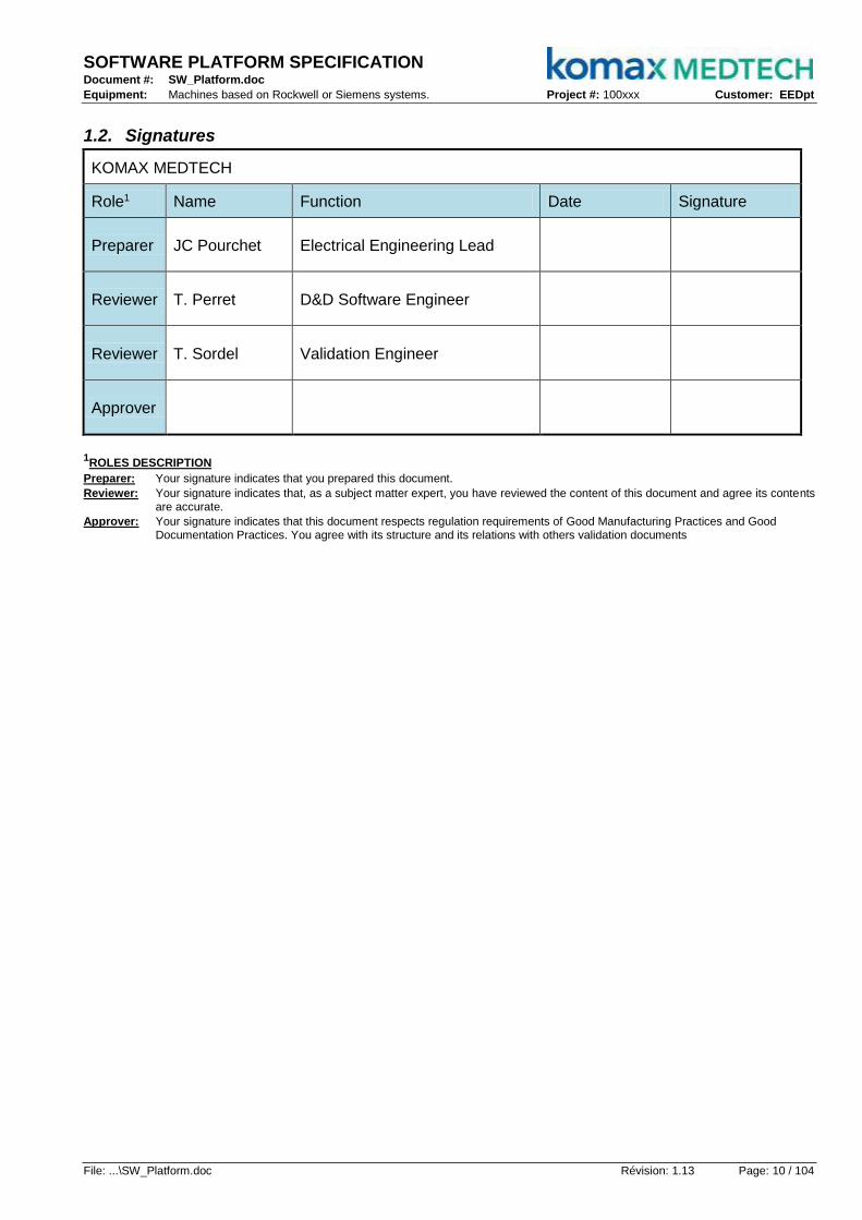
SOFTWARE PLATFORM SPECIFICATION Document #: SW_Platform.doc
Equipment: Machines based on Rockwell or Siemens systems. Project #: 100xxx Customer: EEDpt
File: ...\SW_Platform.doc Révision: 1.13 Page: 10 / 104
1.2. Signatures
KOMAX MEDTECH
Role1 Name Function Date Signature
Preparer JC Pourchet Electrical Engineering Lead
Reviewer T. Perret D&D Software Engineer
Reviewer T. Sordel Validation Engineer
Approver
1ROLES DESCRIPTION
Preparer: Your signature indicates that you prepared this document.
Reviewer: Your signature indicates that, as a subject matter expert, you have reviewed the content of this document and agree its contents are accurate.
Approver: Your signature indicates that this document respects regulation requirements of Good Manufacturing Practices and Good Documentation Practices. You agree with its structure and its relations with others validation documents
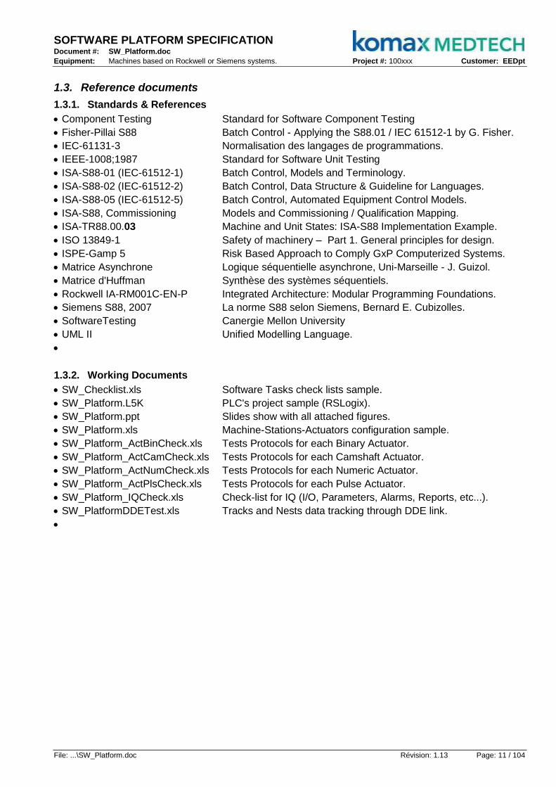
SOFTWARE PLATFORM SPECIFICATION Document #: SW_Platform.doc
Equipment: Machines based on Rockwell or Siemens systems. Project #: 100xxx Customer: EEDpt
File: ...\SW_Platform.doc Révision: 1.13 Page: 11 / 104
1.3. Reference documents
1.3.1. Standards & References
Component Testing Standard for Software Component Testing
Fisher-Pillai S88 Batch Control - Applying the S88.01 / IEC 61512-1 by G. Fisher.
IEC-61131-3 Normalisation des langages de programmations.
IEEE-1008;1987 Standard for Software Unit Testing
ISA-S88-01 (IEC-61512-1) Batch Control, Models and Terminology.
ISA-S88-02 (IEC-61512-2) Batch Control, Data Structure & Guideline for Languages.
ISA-S88-05 (IEC-61512-5) Batch Control, Automated Equipment Control Models.
ISA-S88, Commissioning Models and Commissioning / Qualification Mapping.
ISA-TR88.00.03 Machine and Unit States: ISA-S88 Implementation Example.
ISO 13849-1 Safety of machinery – Part 1. General principles for design.
ISPE-Gamp 5 Risk Based Approach to Comply GxP Computerized Systems.
Matrice Asynchrone Logique séquentielle asynchrone, Uni-Marseille - J. Guizol.
Matrice d'Huffman Synthèse des systèmes séquentiels.
Rockwell IA-RM001C-EN-P Integrated Architecture: Modular Programming Foundations.
Siemens S88, 2007 La norme S88 selon Siemens, Bernard E. Cubizolles.
SoftwareTesting Canergie Mellon University
UML II Unified Modelling Language.
1.3.2. Working Documents
SW_Checklist.xls Software Tasks check lists sample.
SW_Platform.L5K PLC's project sample (RSLogix).
SW_Platform.ppt Slides show with all attached figures.
SW_Platform.xls Machine-Stations-Actuators configuration sample.
SW_Platform_ActBinCheck.xls Tests Protocols for each Binary Actuator.
SW_Platform_ActCamCheck.xls Tests Protocols for each Camshaft Actuator.
SW_Platform_ActNumCheck.xls Tests Protocols for each Numeric Actuator.
SW_Platform_ActPlsCheck.xls Tests Protocols for each Pulse Actuator.
SW_Platform_IQCheck.xls Check-list for IQ (I/O, Parameters, Alarms, Reports, etc...).
SW_PlatformDDETest.xls Tracks and Nests data tracking through DDE link.

SOFTWARE PLATFORM SPECIFICATION Document #: SW_Platform.doc
Equipment: Machines based on Rockwell or Siemens systems. Project #: 100xxx Customer: EEDpt
File: ...\SW_Platform.doc Révision: 1.13 Page: 12 / 104
Rapid
Application
Development
Standards
&
References
Good
Automation
Practices
2. Executive Summary
2.1. Preliminary
Automated machine programming is typically done by software engineers, machine designers, and system integrators. The form and style of the machine software ranges from modular, to monolithic in nature. The objective of this project is to specify the application of a common software methodology that is consistent with the modular programming of automated machinery as described in the ISA-88 standard. This project enables a consistent method of machine interconnection and operability.
2.2. Objective
In pharmaceutical industry the most required systems are Rockwell or Siemens.
2.2.1. One Goal
The SW_Platform defines 1 design guide lines for 2 PLC so only one HMI should comply with anyone.
2.2.2. Three Needs
Beside the unique HMI goal, there are 3 targets to keep in mind:
2.2.2.1. Standard & References (State of the Art)
versus ISA-S88, ISA-TR88.02 and ISO-13849
2.2.2.2. Good Automation Practices
with specifications, tests and validation
2.2.2.3. Rapid Application Development
"Time is money", "Ready early", ...
2.2.3. Five E2ASY Paths
After few technical performance tests, activity based costing analysis and normative references studies, the 5 following matters appear to be the right paths to achieve the 3 main targets.
2.2.3.1. Emulation for early de-risking + Fail Safe for auto-recovery
To pre-test and failure-compensate process sequences
2.2.3.2. Effectiveness for ahead diagnostics
Detailed real-time OEE at every level for ahead diagnosis and to identify predictable failures
2.2.3.3. Agility for last minute changes
Through combination of specialization ability and flexible aggregation, "lego mindstorm"
2.2.3.4. Simplicity always in mind
To make programs running earlier and faster with less files, data, code, bugs, pain, money...
2.2.3.5. Yes we comply
With standards & references so we reuse supplier's codes without reinventing wheel.
Only One
HMI-SCADA
For Two
Hardwares
Effectivenessahead diagnosis
with O.E.E.
Emulationfor de-risking
& Fail Safe
Simplicityalways
in mind
Yeswe comply
to standards
Agilityfor "last minute"
changes

SOFTWARE PLATFORM SPECIFICATION Document #: SW_Platform.doc
Equipment: Machines based on Rockwell or Siemens systems. Project #: 100xxx Customer: EEDpt
File: ...\SW_Platform.doc Révision: 1.13 Page: 13 / 104
2.2.4. Key points Summary
This platform is ready in ladder and structured-text (two PLC prototypes are coded). It applies the rules promoted by ISA-TR88. 8 reusable routines are defined (Admin, Prog, Track, Nest, Bin, Num, Cam and Pls) and the task "Admin" contains 3 routines (logic-actuators-alarm). Compared with the 1200 instructions lines of the 60 routines of current platforms, these 11 basic routines requires around 100 lines that give technical and economical affordable "modular testing". By testing three instructions lines at a time, this platform is validated in white box after 35 hr of effort (with prior written tests).
2.2.4.1. Three major needs
• Compliance TR88, 1st model for mecatronics iAssembly and Packaging industries.
• Rapid application development software, "ARD" to reduce costs.
• Adoption of best automation practices (Gamp 5).
2.2.4.2. 5 outstanding features
• Emulation with actuators included for offline de-risking and online safe mode ability.
• Real-time OEE included in each module for self-diagnostic and preventive maintenance.
• Agility by recombination of the 4 elementary actuators already established on PDS, and EQW1 RAI01.
• Simplicity with only 3 routines per station (logic-actuators-motions) and only 1 config file per machine.
• Compatibility with TR88 and Gamp5 (modes, states, alarms, data-in, data-out, mnemonics, etc. ...)
2.2.4.3. 4 elementary managers manage the following features
• The OEE in real-time in the three managers (Admin, Track and Nest).
• Enhanced limp mode by selecting Nests and / or Tracks.
• Synchronous and asynchronous sequencer (program).
• Management of operating modes and states (Admin).
• Part-ID and Shift-Register data monitoring.
• Management of multiple recipes (Admin).
• Batch Management (Admin).
• Consecutive errors.
• etc ...
2.2.4.4. 4 elementary actuators incorporate the following features
• Single or dual acknowledgement for alarm (HMI and / or Enclosure).
• The safety and self-recovery after operator acknowledgement.
• Manual controls without any additional programming.
• The real-time OEE calculations in the 4 actuators.
• The actuators time response emulation.
• Fail Safe Mode by emulation.
• Mirroring (probe mode).
• etc ...
2.2.4.5. In addition
The automatic generation of "test cases" and modelling "control activity" (HMI, SCADA, Recipe, Batch, etc. ...) is still in progress. The configuration file defining sequencers and data of one machine with its stations have a macro that generates the symbols and instructions lines directly into a Rockwell PLC; the same configuration file also contains all the required information for a machine SDS.
To terminate and by joining the actual software platform activity based costing, Komax should be able to save between 30% and 40% of software development cost while complying to medical requirements.

SOFTWARE PLATFORM SPECIFICATION Document #: SW_Platform.doc
Equipment: Machines based on Rockwell or Siemens systems. Project #: 100xxx Customer: EEDpt
File: ...\SW_Platform.doc Révision: 1.13 Page: 14 / 104
2.3. Document Summary
The main purpose of this document is to describe how to implement the E2ASY paths to achieve the 3 main targets (State of the Art, Good Automation Practices and Rapid Application Development); to do so, the first chapter summarizes the Gamp advises while the second proposes a design process that comply with the normative references; the latest chapters give practices details for hardware interfaces, administration, machine, station and actuator software design.
2.3.1. Gamp Guide Lines
Gamp guidance aims to achieve computerized systems that fit for intended use and meet current regulatory requirements, by building upon existing industry good practice in an efficient and effective manner. It promotes the system V life cycle approach; it synthesizes the goals of tests and gives some typical procedures for modular testing. This chapter gives also the standard software project plan, it lists the software categories and our changes control practices.
2.3.2. Design Guide Lines
The design guide lines goes quickly through the ISA-S88 / IEC-61512 models that have initiated the ISA-TR88 (PackML); it shows how it could be structured in matter of physics, configurations, programs, machine modes, machine states, station states and actuator states. Then it reminds UML's analysis that confirms the ISA's arguments wisdom; the analysis feedbacks objects, states, sequential and class diagrams. It depicts the specifics features embedded into every main class such as effectiveness calculations, time response emulation, components agility and simplicity. The configuration conventions are covered by following the TR88 organization through controller administration, machine and station scopes. The last part proposes a design process for software engineer as development guide lines.
2.3.3. Hardware Interfaces
There is no automation software without hardware; this chapter gives a standard topology that complies with machine directive 2006/42/CE. It proposes a classified list of standard components that could be used with this platform and how to drive them from a software point of view. Then it gives short descriptions of operator panel uses, lights tree behaviour and HMI screens requirements.
2.3.4. Admin Details
This chapter gives to the software engineer the keys to configure admin programs; It explains how to size the machine stations, "tracks side" quantity and "nests side" quantity; It goes again through every public tags that have been considered as "Admin" components; It reminds the "Admin" components could be locally or remotely controlled; It describes the dedicated HMI screen.
2.3.5. Machine Details
This chapter gives to the software engineer the keys to configure a machine programs; it shows how to configure station tags, private and public; it describes the dedicated HMI screen.
2.3.6. Asynchronous Stations Details
This chapter gives to the software engineer the keys to configure asynchronous (or transactional) station programs; it explains how to configure actuators, its "tracks side" quantity and "nests side" quantity; It gives clues to make the sequencer that manage the chosen actuators; It shows how to configure station tags, private and public; It describes the dedicated HMI screen.
2.3.7. Synchronous Stations Details
This chapter gives to the software engineer the keys to configure camshaft synchronous station programs; most of it is the same as asynchronous station but it explains how to merge the standard sequencer to the camshaft follower.
2.3.8. Actuators Details
This chapter gives to the software engineer the keys to configure actuators instructions;
It shows some examples how to choose, instance and configure the right actuator class.

SOFTWARE PLATFORM SPECIFICATION Document #: SW_Platform.doc
Equipment: Machines based on Rockwell or Siemens systems. Project #: 100xxx Customer: EEDpt
File: ...\SW_Platform.doc Révision: 1.13 Page: 15 / 104
3. Gamp Guide Lines
3.1. V Life Cycle
The V Life Cycle principle structures the development by coordinating the design, implementation and validation phases; successive versions of Gamp have continued to strengthen this model.
PerformanceTesting
User Requirements
Specification
ModulesSpecification
DesignSpecification
FunctionalSpecification
Integration &Modules Test
InstallationTesting
OperationalTesting
MachineMachine
ActuatorsActuators
StationStation
Black BoxBlack Box
BlackBox
BlackBox
WhiteBox
WhiteBox
Configuration _00
–
+Configuration _01
Main form _01Tags List _01
+ Sub form _01_00
Sub form _01_01
Sub form _01_02• Actuators List• Station Sequences
–
–
Project _A
Project _B
+
Sub form _01_010++
• Stations List• Mach. Sequences
The downswing starts with the customer's specifications that the supplier translates into multidisciplinary functional specifications, which means they are common to all trades that the provider must implement to achieve the final product.
These functional approaches are then taken up sector by sector (mechanical design, hardware and software) to prepare design specifications, those ones, because of their too high level of abstraction, are again taken to be detailed to establish concrete references to the implementation phase.
The design phase ends with the jobs (mechanics, hardware & software) specifications writing of the modules, these specifications are translated into mechanical drawings, electrical diagrams and software diagrams (states, objects, sequences or classes).
The upswing is completely symmetric in terms of tests, so from Gamp, a different type of test is required for each phase of implementation, so the pre-integration tests validate the modular testing achievements, the installation validate the jobs requirements, the operational tests confirm the choices and finally the functional performance tests qualify the final product relative to customer specifications.

SOFTWARE PLATFORM SPECIFICATION Document #: SW_Platform.doc
Equipment: Machines based on Rockwell or Siemens systems. Project #: 100xxx Customer: EEDpt
File: ...\SW_Platform.doc Révision: 1.13 Page: 16 / 104
3.2. Tests Overview
3.2.1. Objectives
Ensure proper operation on the specifications of a portion of the program (called "unit" or "module"):
o A test procedure for each module.
o A test module independent from the rest of the program.
o Ensure that performance correlates the specification of that module.
o All tests must be replayed after a code change to ensure the absence of instabilities.
The Extreme Programming advocates writing the test procedure at the same time that the function of the module is coded.
3.2.2. Modules
All software studio providers offers a standard way of viewing the project organization and may be called "Program Organization", "Project Explorer" or "POU", they all have the purpose to show a tree to determine the overall software modules nesting into each other or with each other ...
Therefore each of the icons listed in the Explorer is a module that can be tested with the exception of modules that contain only data ("tags") is still the case because most controllers are not yet fully object-oriented and continue to separate data programming instructions or code.
3.2.3. Box
3.2.3.1. Black
Example: the transistor
A "black box" is a module of unknown internal composition (voluntarily or not).
The black box test is used to verify that the results are the expected ones for given conditions. It is therefore appropriate as soon as the test is more important than the code behind.
3.2.3.2. White
Example: the bicycle
A "white box" is a module which can forecast every feature because all components are visible.
The white box testing is done by scanning the source code of the module during its own execution; the online stepping mode could be a mean to achieve this test.

SOFTWARE PLATFORM SPECIFICATION Document #: SW_Platform.doc
Equipment: Machines based on Rockwell or Siemens systems. Project #: 100xxx Customer: EEDpt
File: ...\SW_Platform.doc Révision: 1.13 Page: 17 / 104
3.2.4. Komax Rules
Unit tests take place before the installation tests stage: they are part of the integration testing stage; the protocols contents of these tests are based on modules specifications.
ModulesSpecification
Integration &Modules Test
MachineMachine
ActuatorsActuators
StationsStations
Black BoxBlack Box
BlackBox
BlackBox
WhiteBox
WhiteBox
Code In Scope:-Custom Process-Parts Information-Batch Supervision
Tests applicable on functions identified as critical on the pFMEA
Tests applicable on actuators identified as high-risk class in the SRA
pFMEA
S R A
3.2.5. Software Architecture
Unit testing is necessarily dependent on the chosen software architecture, in the field of assembly or packaging automatic machines, the latest standards require the following architecture: a machine is divided into stations and each station is an aggregate of actuators.
These standards describe only how to structure portions of program support to automate processes, parts of program schedules related to "Firmware" or "Fieldbus" commonly called "Platforms" are not affected.
3.2.6. Architecture & Scope
For the validation of a machine and only in case the base system comes from a recognized provider (Siemens or Rockwell the platform testing are not required; at most, the end customer may request a certificate respect of the recommendations of use ("good practices") established by the provider after an audit of our PLC platform using Komax guide lines.
3.2.6.1. "Out of scope"
We consider "beside" codes related to the systems (Siemens or Rockwell) integration in our platform does not fall within the scope of unit testing.
3.2.6.2. "In the scope"
We consider the specifically written code to automate processes required to assemble, process or trace the product for the custom application enters in the scope of unit testing.
3.2.6.3. Risky Station
In fact, all modules are tested more or less by programmers, electricians and mechanics between the machine power-up, configuration and tune-up. Therefore some unit tests are probably not needed on the whole modules in charge of the process of a machine, a machine would not consider every station as risky for the product. For unit tests, we consider only the modules belonging to stations where a risky process is identified.
3.2.6.4. Black Box Scope
Modules and sub-modules of a "risky station" identified by the "Software Risk Analysis" black box
are tested, including the main module when its white box testing is done.
3.2.6.5. White Box Scope
Only the main module of a "risky station" is subject of a white box test.

SOFTWARE PLATFORM SPECIFICATION Document #: SW_Platform.doc
Equipment: Machines based on Rockwell or Siemens systems. Project #: 100xxx Customer: EEDpt
File: ...\SW_Platform.doc Révision: 1.13 Page: 18 / 104
3.3. Tests Procedures
3.3.1. Black Tests
To describe a black box, we recommend the "State Transition Testing".
Test cases must execute transitions between states and require the following information:
- The initial state and the existing entries.
- The expected results and / or the final state expected.
Test cases are designed to execute valid transitions between states.
They can also be designed to test unspecified transitions.
3.3.1.1. "State transition"
StationMachine
Black Box(dT, Step, ...)
Safe
Ack.Alarm
Emulate
Act#1
Ab
ort
Ex
ec
Idle
Go
od
Step-by-Step
Act#2 Act#3
Equations:
_Alarm = Act#1.AlmOff+Act#1.AlmOn+...
_Good = Act#1.Sts x Act#2.Sts x ~Act#3.Sts
_Idle = ~Act#1.Sts x ~Act#2.Sts x Act#3.Sts
_Step = Abort + Exec x 10
Actuator
Black Box(dT, ...)
Ack
. . .
Alm OFF
Alm ON
Command Status
Input Output
Equations:
_Status = Input + Emulate x dT.Done
_AlmOn = Cmd x ~Sts x dT.Done
_AlmOff = ~Cmd x Sts x dT.Done
_Output = Cmd x ~Ack x ~AlmOn
Em
ula
te
3.3.1.2. Imperative vs Sequencing Logic
Black tests are enough for the components programmed under imperative logic (low level).
StationMachine
White Box
Safe
Ack.Alarm
Emulate
Ab
ort
Ex
ec
En
d
Go
od
Step-by-Step 'Header:
_If Abort=1 thenSeq:=1
_If Exec=1 thenSeq:=10
'Sequences:_If Seq=1 then
Act#1.Cmd:=0Seq:=2
_If Step=2 and Act#1.Sts=0 then Seq:=3
_If Seq=3 then ..._. . .
StationMachine
Black Box(dT, Step, ...)
Safe
Ack.Alarm
Emulate
Act#1
Ab
ort
Ex
ec
Idle
Go
od
Step-by-Step
Act#2 Act#3
Equations:
_Alarm = Act#1.AlmOff+Act#1.AlmOn+...
_Good = Act#1.Sts x Act#2.Sts x ~Act#3.Sts
_Idle = ~Act#1.Sts x ~Act#2.Sts x Act#3.Sts
_Step = Abort + Exec x 10
Once a component is programmed in sequential logic, a blank test is required.

SOFTWARE PLATFORM SPECIFICATION Document #: SW_Platform.doc
Equipment: Machines based on Rockwell or Siemens systems. Project #: 100xxx Customer: EEDpt
File: ...\SW_Platform.doc Révision: 1.13 Page: 19 / 104
a Clean...
b Load...
c Shift...
d Unload...
x Open...
y Down...
z Close...
Load...
Machine...
x ...
Clean...
x ...
Shift...
x ...
Unload...
Act#
b1
Act#
b2
Act#
b3
Act#
d1
Act#
d2
Act#
c1
Act#
c2
Act#
a1
Act#
a2
Process Machine Process Stations and Actuators
Pro
ced
ure
sIm
pera
tif
3.3.2. White Tests
To qualify a white box, we recommend the "Branch / Decision Testing" in cases of logical sequenced and the "Data Flow Testing" in other cases (i.e. "Part Info" or "Shift-Register").
3.3.2.1. "Data Flow"
This analysis identifies the interactions between components connected by data flow and / or flow control. The test cases are designed to perform transfers between variables or values of components and require the following information:
The input variables.
Places of definition of variables and pairs of uses.
The subsets of control flow (s) to run.
Expected results.
3.3.2.2. "Branch/Decision"
The source code analysis make possible the branches identification with their expected results. A branch is an instruction executed in a conditional expression. Test cases are designed to execute combinations of values in the branches and require the following information:
Identification and inputs of each branch.
The identification of combinations of values to run.
The expected results and / or identification of the next branch.
Under sequential logic, this technique requires a "step by step" mode of operation.
3.3.2.3. Standard Model
Here the number of programs to be tested in white boxes is the number of existing stations.

SOFTWARE PLATFORM SPECIFICATION Document #: SW_Platform.doc
Equipment: Machines based on Rockwell or Siemens systems. Project #: 100xxx Customer: EEDpt
File: ...\SW_Platform.doc Révision: 1.13 Page: 20 / 104
FDS.doc
URS.doc
SDS.doc
HDS.doc Draw
.dwg
Diag..xls Code
.plc
FDS.doc
HDS.doc
SDS.docTest
.xls
FDS.doc
Install.IQ
Oper..OQ
HDS.doc
SDS.doc
Perf.PQ
Alpha
or Beta
Release
Candidate
Release
Candidate
Gold
Release
Gold
Release
.plcCode
.xlsTest.xls
Conf.
.drwDraw
Design Code Debug Test-up
upSet
3.4. Software Plan
The following plan is booked to any software project and is coordinated with specifications.
3.4.1. Design
FDS alpha.
o Machine modelling by breaking machine to stations and then stations to actuators.
o Configuration of .machine & stations
o Risk analysis under pFMEA method.
o Design review.
Configuration alpha.
FDS release candidate.
3.4.2. Code
HDS + SDS alpha.
o Configuration of Inputs and outputs data (alarms, parameters, reports, outputs, inputs, etc....).
o PLC programming, start with tags importation and then sequences encoding.
o HMI screens, Displays design for machine and station(s).
o Code review.
Code alpha.
3.4.3. Setup
Configuration release candidate.
o Electrical booting, machine power-up.
o Hardware configuration, field bus setup, motion axis tune, distributed I/O mapping, etc...
o Physical Input/Output check, hardware control of electrical signals from PLC.
o Parameters initialization, machine and stations configurable data typing.
o Camshafts initialization, configurable cam angles typing.
HDS release candidate.
3.4.4. Debug
Code release candidate.
o Maintenance items, every manual function tests.
o Nominal speed cycle, complete automatic cycle station by station.
o Statistics displays, pre-test correctness of displayed data updates on HMI.
o Alarms displays, inputs forcing to pre-test alarms (number and descriptions).
o Branch tests, step-by-step pre-test control versus configuration spreadsheets.
SDS release candidate.
3.4.5. Test-Up
FDS gold release.
o Inputs check, final test for inputs and alarms
o Modules tests, final black box tests (only for categories 5 software parts)
o Installation tests, i.e. validation plan.
o Operational tests, i.e. validation plan.
o Performance tests, i.e. validation plan.
Configuration + Code + Test + HDS + SDS gold release.

SOFTWARE PLATFORM SPECIFICATION Document #: SW_Platform.doc
Equipment: Machines based on Rockwell or Siemens systems. Project #: 100xxx Customer: EEDpt
File: ...\SW_Platform.doc Révision: 1.13 Page: 21 / 104
"EQW1_M12_V106_06jun2011.ACD"
Project
Name
Machine
Name
Revision
Number
Revision
Date
3.5. Categories
To agree with Gamp guide lines, the following list is filled for every software project.
3.5.1. Operational system
3.5.2. Firmware
3.5.3. Standard software package
3.5.4. Configurable software package
3.5.5. Fitted software
GAMP – Software categories
Software parts Cat. Software parts Cat.
Komax PLC Software 5 Komax HMI Software 4 or 5
PLC – Design tools (Studio) 3 HMI – Design tools (Studio) 3
3.6. Changes Control
The software revision number is a part of the PLC project naming convention.
It defines the file name (with the date).
It defines the controller name (without the date).
3.6.1. Revisions Numbering
_.xx while the software project is controlled by the software engineer in charge of coding.
0.00 Right after "Inputs Check" at the beginning of "Test-Up" (see §5.1).
0.xx while "Modules Tests" without "Revisions Traceability" but with "Program header update".
1.00 right after "Integration Tests"
1.xx while "Operational and Performance Tests" with "Revisions Traceability".
2.00 right after the FAT.
2.xx after the FAT with "Revisions Traceability".
3.6.2. Revisions Traceability
A word document is attached to each revision; it describes each change with screenshots of codes changes (before and after) and with a comment of the modification; this makes the change historics, which includes "Test Reference", "Modification Title", "Why" reason, date and author.
3.6.3. Program Header Update
To be described...
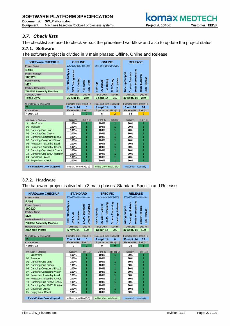
SOFTWARE PLATFORM SPECIFICATION Document #: SW_Platform.doc
Equipment: Machines based on Rockwell or Siemens systems. Project #: 100xxx Customer: EEDpt
File: ...\SW_Platform.doc Révision: 1.13 Page: 22 / 104
3.7. Check lists
The checklist are used to check versus the predefined workflow and also to update the project status.
3.7.1. Software
The software project is divided in 3 main phases: Offline, Online and Release
# # #
## Main + Stations
∞ Mainframe
00 Transport
01 Damping Cup Load
02 Damping Cup Check
03 Damping Compound Disp.1
07 Damping Compound Vision
08 Retraction Assembly Load
09 Retraction Assembly Check
18 Damping Cup Nest A Check
19 Damping Cup 1080° Rotation
24 Good Part Unload
25 Empty Nest Check 100% 1
100% 1
never edit - read only
90% 1
70% 1
edit at sheet initialization
100% 1
100% 1
100%
100%
100%
100%
1
1
100%
100%
100%
Software Owner
Tom & Jerry
Fields Edition Colors Legend edit and also Risk [1-3]
1
100% 1
Current Date
7 sept. 14
Work Hr per 7 days week
20
7280655 Assembly Machine
M24Machine Description
SOFTware CHECKUP
RAI02
Project Number
Machine Name
100120
Project Name
70%
PL
C C
od
ing
HM
I S
etu
p
SD
S D
raft
Tu
ne-u
p S
up
po
rt
Dry
-ru
n S
uccess
Tests
Pre
req
uis
ites
1
100%
1
70%
100%
22
90%
90%
70%
90%
1
Risk [1-3]
1
1
1
1
1
1
1
1
70%
1
100%
1 100%
1
1
70% 1
190%
11
70%
1
1
Done %
100%
100%
Risk [1-3]
1
Risk [1-3]
100%
1
1
100%
100% 1
100% 1
100%
0 0
Expected Hr Risk [1...]
30 juin 14 240
Due Date
7 sept. 14
Expected Date Rated Hr
0
Due Hr
641 oct. 145Risk [1...]
6
Expected Hr
64
Expected DateRated Hr
9 sept. 14
Done %
100%
Done %
30 sept. 14 240
Expected Hr Risk [1...]
Rated HrExpected Date
PL
C D
eb
ug
I/O
Deb
ug
Due Hr
9 sept. 14 240
RELEASE
Due HrDue Date
Tests
Su
pp
ort
s
SD
S R
ele
ase
Due Date
OFFLINE ONLINE
UR
S+
FD
S A
naly
sis
SD
S C
on
fig
ura
tio
n
SD
S U
pd
ate
Bo
ot-
Up
20%+20%+20%+20%+20% 20%+20%+20%+20%+20%
HM
I D
eb
ug
3.7.2. Hardware
The hardware project is divided in 3 main phases: Standard, Specific and Release
5 # 5
## Main + Stations
∞ Mainframe
00 Transport
01 Damping Cup Load
02 Damping Cup Check
03 Damping Compound Disp.1
07 Damping Compound Vision
08 Retraction Assembly Load
09 Retraction Assembly Check
18 Damping Cup Nest A Check
19 Damping Cup 1080° Rotation
24 Good Part Unload
25 Empty Nest Check
0
20%+20%+20%+20%+20% 20%+20%+20%+20%+20%
Risk [1...]
7 sept. 140
13 juin 14
Ris
k A
naly
sis
200
Due Date
I/O
Revie
w
B.O
.M.
Sta
nd
ard
UR
S+
FD
S A
naly
sis
Ord
ers
Sta
nd
ard
HD
S D
raft
I/O
Lis
t +
Dis
trib
.
RELEASE
Due HrDue Date
Ord
ers
Rem
ain
ing
Bin
der
Rele
ase
HD
S R
ele
ase
Dra
win
gs R
ele
ase
SPECIFIC
Due Hr
20%+20%+20%+20%+20%
100
100%
1930 sept. 14
Rated Hr
30 sept. 14
Expected Hr Expected Hr
Done %
1
Risk [1-3]
100%
1
1
1100%
1
1
1100%
0
1
Done %
Expected Date
Due Date
5 févr. 14 100
Due Hr
100%
0
1
100%
1
100%
100%
100%
100%
80%
80% 1
80% 1
80%
1
10
90%
90%
80%
Risk [1-3]
1
1
1
80%
80%
1
1
1
1
80% 1
1
Current Date
7 sept. 14
Work Hr per 7 days week
Risk [1...]Risk [1...]
Rated Hr
20
RAI02
Project Number
Machine Name
100120
Hardware Owner
Jean-Noel Picaud
7280655 Assembly Machine
HARDware CHECKUP
Project Name
100%100%
M24Machine Description
B.O
.M.
Rem
ain
ing
Wir
ing
Su
pp
ort
Dra
win
gs U
pd
ate
s
STANDARD
100%
10
100%
Done %
100%
100%
100%
Expected Hr
1
100%
7 sept. 14
0
100% 1
1
100%
Fields Edition Colors Legend edit and also Risk [1-3]
1
100% 1
1
1
edit at sheet initialization never edit - read only
Expected Date Rated Hr Expected Date
100% 1 100% 1
100% 1
Tests
Pre
req
uis
ites
Risk [1-3]
1
80% 1
80% 1
1

SOFTWARE PLATFORM SPECIFICATION Document #: SW_Platform.doc
Equipment: Machines based on Rockwell or Siemens systems. Project #: 100xxx Customer: EEDpt
File: ...\SW_Platform.doc Révision: 1.13 Page: 23 / 104
4. Design Guide Lines
4.1. ISA-IEC's Models
4.1.1. S88 / 61512
The diagram shown here are specific in terms of the functionality they provide but can be implemented in various ways to fit most automated machinery and machine controllers; therefore the figures do not follow the standard UML guidelines for depiction of software flow.
Procedural
Model
Operation (s)
Recipe
Procedure (s)
Phases
Procedural
Model
Operation (s)
Recipe
Procedure (s)
Phases
Operation (s)
Process
Stage (s)
Actions
Process
Model
Operation (s)
Process
Stage (s)
Actions
Process
Model
Unit (s)
Area (s)
Cell (s)
Equipments
Modules
Physical
Model
Plant (s)
Enterprise
Unit (s)
Area (s)
Cell (s)
Equipments
Modules
Physical
Model
Plant (s)
Enterprise
Activity
Model
Process Management
Unit (s) Supervision
Process
ControlP
roduction,
Pla
nnin
g a
nd
Schedu
ling
Recip
es
Managem
ent
Info
rmation
Managem
ent
Activity
Model
Process Management
Unit (s) Supervision
Process
ControlP
roduction,
Pla
nnin
g a
nd
Schedu
ling
Recip
es
Managem
ent
Info
rmation
Managem
ent
4.1.2. TR88 / PackML
If automated machinery is modelled in an ISA-S88 physical hierarchy, it is possible that a machine can represent the unit level in this hierarchy; It also known as PackML standard.
Procedural
Model
▼ ▼ ▲ ▲ ▼ ▼ ▲ ▲
Actuators
▼ ▼ ▲ ▲ ▼ ▼ ▲ ▲
▼ ▼ ▲ ▲ ▼ ▼ ▲ ▲
Actuators
▼ ▼ ▲ ▲ ▼ ▼ ▲ ▲▼ ▲▼ ▲▼ ▲▼ ▲
Stations
▼ ▲▼ ▲
▼ ▲▼ ▲▼ ▲▼ ▲
Stations
▼ ▲▼ ▲▼ ▲ ▼ ▲
Machine(s)
▼ ▲ ▼ ▲
▼ ▲ ▼ ▲
Machine(s)
▼ ▲ ▼ ▲▼ ▲▼ ▲
Line(s)
▼ ▲▼ ▲
▼ ▲▼ ▲
Line(s)
▼ ▲▼ ▲
Activity
Model
Process Management
Unit (s) Supervision
Process
Control
Pro
duction,
Pla
nnin
g a
nd
Schedulin
g
Recip
es
Managem
ent
Info
rmation
Managem
ent
Unit (s)
Area (s)
Cell (s)
Equipments
Modules
Physical
Model
Plant (s)
Enterprise
Unit (s)
Area (s)
Cell (s)
Equipments
Modules
Physical
Model
Plant (s)
Enterprise
SOFTWARE PLATFORM SPECIFICATION Document #: SW_Platform.doc
Equipment: Machines based on Rockwell or Siemens systems. Project #: 100xxx Customer: EEDpt
File: ...\SW_Platform.doc Révision: 1.13 Page: 24 / 104
4.1.2.1. Line
A Line (Cell) contains all of the Machines (Unit), Station (equipment) and Actuator (module) required to make one or more batches.
Process control activities must respond to a combination of control requirements using a variety of methods and techniques. Requirements that cause physical control actions may include responses to process conditions or to comply with administrative requirements.
A frequently recognized subdivision of a Line (Cell) is the train. A train is composed of all Machines (Unit) and other Stations (equipment) that may be utilized by a specific batch. A batch does not always use all the Stations (equipment) in a train. Furthermore, more than one batch and more than one product may use a train simultaneously. The order of equipment actually used or expected to be used by a batch is called the path. Although a Line (Cell) may contain more than one train, no train may contain equipment outside the boundaries of the Line (Cell).
A Line is a logical grouping of equipment that includes the equipments required for production of one or more batches. It defines the span of logical control of one set of process equipments within an area. The existence of the Line allows for production scheduling on a Line basis, and also allows for Line-wide control strategies to be designed. These Line-wide control strategies might be particularly useful in emergency situations.
4.1.2.2. Machine
A Machine (unit) is made up of Stations (equipment) and Actuators (module). The Actuators (module) that make up the Machine (unit) may be configured as part of the Machine (unit) or may be acquired temporarily to carry out specific tasks.
One or more major processing activities can be conducted in a Machine (unit). It combines all necessary physical processing and control Stations (equipment) required to perform those activities as an independent Station (equipment) grouping. It is usually centred on a major piece of processing Stations (equipment). Physically, it includes or can acquire the services of all logically related Stations (equipment) necessary to complete the major processing task(s) required of it. Machines (unit) operate relatively independently of each other.
A Machine (unit) frequently contains or operates on a complete batch of material at some point in the processing sequence of that batch. However, in other circumstances it may contain or operate on only a portion of a batch. This standard presumes that the Machine (unit) does not operate on more than one batch at the same time.
4.1.2.3. Station
Physically, the Station (equipment) may be made up of Actuators (module) and subordinate Stations (equipment). A Station (equipment) may be part of a Machine (unit) or a stand-alone Stations (equipment) grouping within a line. If engineered as a stand-alone Station (equipment) grouping, it can be an exclusive-use resource or a shared-use resource.
A Station (equipment) can carry out a finite number of specific minor processing activities such as dosing and weighing. It combines all necessary physical processing and Actuators (module) required to perform those activities. Functionally, the scope of the Station (equipment) is defined by the finite tasks it is designed to carry out.
4.1.2.4. Actuator
An Actuator (module) is typically a collection of sensors, probes, valves, motors, other Actuators (module), and associated Stations (equipment) interlocks that, from the point of view of control, is operated as a single entity. An Actuator (module) can also be made up of other Actuator (module). For example, a header Actuator (module) could be defined as a combination of several on/off automatic block valve.
Some examples of Actuators (module) are
a regulating device consisting of a transmitter, a controller, and a control valve that is operated via the set point of the device;
a state-oriented device that consists of an on/off automatic block valve with position feedback switches, that is operated via the set point of the device;
A header that contains several on/off automatic block valves and that coordinates the valves to direct flow to one or several destinations based upon the set point directed to the header actuator.
Note: Actuators (module) do not perform procedural control, only imperative (ISA-S88 §5.2.2.4.2).
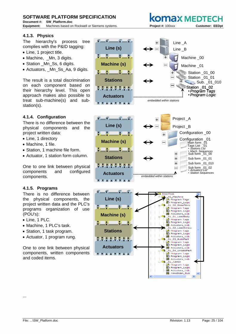
SOFTWARE PLATFORM SPECIFICATION Document #: SW_Platform.doc
Equipment: Machines based on Rockwell or Siemens systems. Project #: 100xxx Customer: EEDpt
File: ...\SW_Platform.doc Révision: 1.13 Page: 25 / 104
4.1.3. Physics
The hierarchy's process tree complies with the P&ID tagging:
Line, 1 project title.
Machine, _Mn, 3 digits.
Station _Mn_Ss, 6 digits.
Actuators, _Mn_Ss_Aa, 9 digits.
The result is a total discrimination on each component based on their hierarchy level. This open approach makes also possible to treat sub-machine(s) and sub-station(s).
4.1.4. Configuration
There is no difference between the physical components and the project written data:
Line, 1 directory
Machine, 1 file.
Station, 1 machine file form.
Actuator, 1 station form column.
One to one link between physical components and configured components.
4.1.5. Programs
There is no difference between the physical components, the project written data and the PLC's programs organization of use (POU's):
Line, 1 PLC.
Machine, 1 PLC's task.
Station, 1 task program.
Actuator, 1 program rung.
One to one link between physical components, written components and coded items.
...
–
+ Machine _00
Machine _01
+ Station _01_00
Station _01_01–
Station _01_02 • Program Tags• Program Logic
–Station _01_02 • Program Tags• Program Logic
–
–
Line _A
Line _B
+
Sub. _01_010+
▼ ▼ ▲embedded within stations
▲ ▼ ▼ ▲ ▲
Actuators
▼ ▼ ▲▼ ▲▼
▲ ▼ ▼ ▲ ▲▼ ▲▼ ▲▲
Stations
▼ ▲▼ ▲▼ ▲ ▼ ▲
Machine (s)
▼ ▲ ▼ ▲▼ ▲▼ ▲
Line (s)
▼ ▲▼ ▲
Configuration _00
–
+Configuration _01
Main form _01Tags List _01
+ Sub form _01_00
Sub form _01_01
Sub form _01_02• Actuators List• Station Sequences
–
–
Project _A
Project _B
+
Sub form _01_010+
▼ ▼ ▲
embedded within stations
▲ ▼ ▼ ▲ ▲
Actuators
▼ ▼ ▲▼ ▲▼
▲ ▼ ▼ ▲ ▲▼ ▲▼ ▲▲
Stations
▼ ▲▼ ▲▼ ▲ ▼ ▲
Machine (s)
▼ ▲ ▼ ▲▼ ▲▼ ▲
Line (s)
▼ ▲▼ ▲
+
• Stations List• Mach. Sequences
▼ ▼ ▲ ▲ ▼ ▼ ▲ ▲
Actuators
▼ ▼ ▲ ▲ ▼ ▼ ▲ ▲▼ ▲▼ ▲▼ ▲▼ ▲
Stations
▼ ▲▼ ▲▼ ▲ ▼ ▲
Machine (s)
▼ ▲ ▼ ▲▼ ▲▼ ▲
Line (s)
▼ ▲▼ ▲

SOFTWARE PLATFORM SPECIFICATION Document #: SW_Platform.doc
Equipment: Machines based on Rockwell or Siemens systems. Project #: 100xxx Customer: EEDpt
File: ...\SW_Platform.doc Révision: 1.13 Page: 26 / 104
▼ ▼ ▲ ▲ ▼ ▼ ▲ ▲
Actuators
▼ ▼ ▲ ▲ ▼ ▼ ▲ ▲▼ ▲▼ ▲▼ ▲▼ ▲
Stations
▼ ▲▼ ▲▼ ▲ ▼ ▲
Machine (s)
▼ ▲ ▼ ▲▼ ▲▼ ▲
Line (s)
▼ ▲▼ ▲
Maintenance
Manual
Emulation
Producing
Process Management
Pro
duction,
Pla
nnin
g a
nd
Schedulin
g
Recip
es
Managem
ent
Info
rmation
Managem
ent
4.1.6. Machine Modes
A Unit/Machine control mode is an ordered subset of states, state commands, and state transitions that determines the strategy for carrying out a unit/machine’s process. Typical Unit control modes are Automatic, Semi-Auto, Manual, Index, Jog, Purge, Clean, Dry Cycle, etc. The distinguishing elements between these Unit control modes are the selected subset of states, state commands, and state transitions.
4.1.6.1. Producing
This represents the mode which is utilized for routine production. The machine executes relevant logic in response to commands which are either entered directly by the operator or issued by another supervisory system. The Base State model below can be used to define a Producing mode that is used in order to deliver control of routine processing and production. It is recognized that machines also require maintenance, calibration, and setting up. To address this requirement two example modes of operation are shown below: Maintenance and Manual.
4.1.6.2. Maintenance
This mode may allow suitably authorized personnel the ability to run an individual machine independent of other machines in a production line. This mode would typically be used for alarm-finding, machine trials, or testing operational improvements. This mode would also allow the speed of the machine to be adjusted (where this feature is available).
It is expected that, because the machine will generally operate in its usual manner, it will need to undergo some or all of its routine starting up procedures. Maintenance mode will follow a recognized unit state model.
4.1.6.3. Manual-Emulation
Manual mode provides suitably authorized personnel the ability to operate individual subordinate equipment controls (such as actuator) within the machine under manual pushbutton control. Such controls in this mode may be on a "hold-to-run" basis such that removal of the run signal will cause the actuator to be stopped. The ability to perform specific functions will be dependent upon mechanical constraints and interlocks. Manual mode will be of particular use for setting up the machine to work.
This provides direct control of individual machine modules. This feature is available depending upon the mechanical constraints of the mechanisms being exercised. This feature may be used for the commissioning of individual actuators, verifying the operation of synchronized actuators, testing the actuator as a result of modifying parameters, etc...
Emulation refers to the ability of a program to emulate (imitate) physical device, in this mode, the time response emulation that is embedded in every actuator could be enabled; it means some machine equipments tune-up could be done even with some missing parts.
4.1.6.4. Purge
User mode to empty the machine (i.e. for cleaning).
4.1.6.5. Dry Cycle
User mode to execute without parts entering in the machine.
4.1.6.6. Single Cycle
User mode to execute only one cycle and ask operator for next one.
4.1.6.7. Limp Track
User mode to execute only on some track(s) (i.e. disable one or more up).
4.1.6.8. Limp Nest
User mode to execute only on some nest(s) (i.e. disable one or more nest).
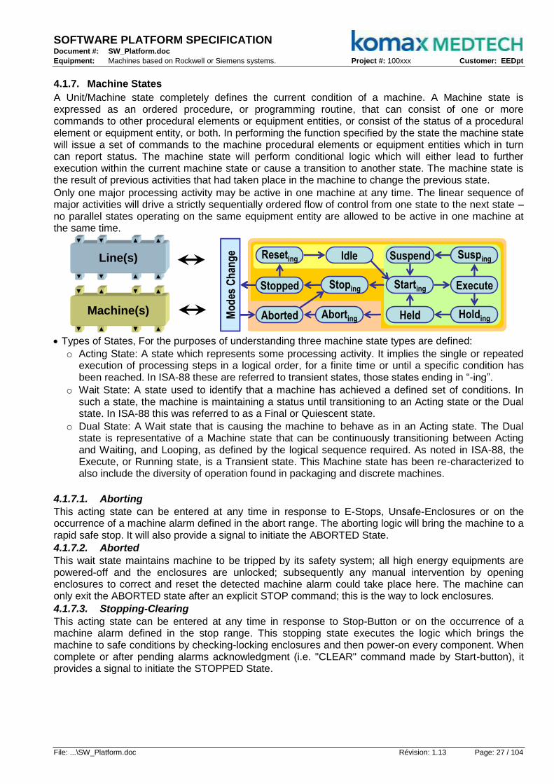
SOFTWARE PLATFORM SPECIFICATION Document #: SW_Platform.doc
Equipment: Machines based on Rockwell or Siemens systems. Project #: 100xxx Customer: EEDpt
File: ...\SW_Platform.doc Révision: 1.13 Page: 27 / 104
4.1.7. Machine States
A Unit/Machine state completely defines the current condition of a machine. A Machine state is expressed as an ordered procedure, or programming routine, that can consist of one or more commands to other procedural elements or equipment entities, or consist of the status of a procedural element or equipment entity, or both. In performing the function specified by the state the machine state will issue a set of commands to the machine procedural elements or equipment entities which in turn can report status. The machine state will perform conditional logic which will either lead to further execution within the current machine state or cause a transition to another state. The machine state is the result of previous activities that had taken place in the machine to change the previous state.
Only one major processing activity may be active in one machine at any time. The linear sequence of major activities will drive a strictly sequentially ordered flow of control from one state to the next state – no parallel states operating on the same equipment entity are allowed to be active in one machine at the same time.
▼ ▲ ▼ ▲
Machine(s)
▼ ▲ ▼ ▲
▼ ▲▼ ▲
Line(s)
▼ ▲▼ ▲
Suspend
Stopped ExecuteStarting
Reseting Susping
Mo
des
Ch
ang
e
Held HoldingAborting
Idle
Stoping
Aborted
Suspend
Stopped ExecuteStarting
Reseting Susping
Mo
des
Ch
ang
e
Held HoldingAborting
Idle
Stoping
Aborted
Types of States, For the purposes of understanding three machine state types are defined:
o Acting State: A state which represents some processing activity. It implies the single or repeated execution of processing steps in a logical order, for a finite time or until a specific condition has been reached. In ISA-88 these are referred to transient states, those states ending in “-ing”.
o Wait State: A state used to identify that a machine has achieved a defined set of conditions. In such a state, the machine is maintaining a status until transitioning to an Acting state or the Dual state. In ISA-88 this was referred to as a Final or Quiescent state.
o Dual State: A Wait state that is causing the machine to behave as in an Acting state. The Dual state is representative of a Machine state that can be continuously transitioning between Acting and Waiting, and Looping, as defined by the logical sequence required. As noted in ISA-88, the Execute, or Running state, is a Transient state. This Machine state has been re-characterized to also include the diversity of operation found in packaging and discrete machines.
4.1.7.1. Aborting
This acting state can be entered at any time in response to E-Stops, Unsafe-Enclosures or on the occurrence of a machine alarm defined in the abort range. The aborting logic will bring the machine to a rapid safe stop. It will also provide a signal to initiate the ABORTED State.
4.1.7.2. Aborted
This wait state maintains machine to be tripped by its safety system; all high energy equipments are powered-off and the enclosures are unlocked; subsequently any manual intervention by opening enclosures to correct and reset the detected machine alarm could take place here. The machine can only exit the ABORTED state after an explicit STOP command; this is the way to lock enclosures.
4.1.7.3. Stopping-Clearing
This acting state can be entered at any time in response to Stop-Button or on the occurrence of a machine alarm defined in the stop range. This stopping state executes the logic which brings the machine to safe conditions by checking-locking enclosures and then power-on every component. When complete or after pending alarms acknowledgment (i.e. "CLEAR" command made by Start-button), it provides a signal to initiate the STOPPED State.

SOFTWARE PLATFORM SPECIFICATION Document #: SW_Platform.doc
Equipment: Machines based on Rockwell or Siemens systems. Project #: 100xxx Customer: EEDpt
File: ...\SW_Platform.doc Révision: 1.13 Page: 28 / 104
4.1.7.4. Stopped
This wait state means machine is powered, safe and stationary after completing the STOPPING state (Enclosures locked). All communications with other systems are functioning (if applicable). A START command will cause the acknowledgement of pending alarms and an exit from STOPPED to the RESETTING state. An ABORT command will cause an exit from STOPPED to ABORTING; this is the way to unlock enclosures.
4.1.7.5. Resetting
This acting state is the result of a START command from the STOPPED state. RESETTING will typically place the machine in a kind of "HOME" state where components are ready to execute process. When complete, it provides a signal to initiate IDLE state.
4.1.7.6. Idle
This wait state indicates that RESETTING is complete ("HOMED"). This state maintains the machine conditions which were achieved during the RESETTING state, and performs operations required when the machine is in IDLE.
4.1.7.7. Starting
This acting state is the result of a maintained START command (local or remote) from the IDLE, SUSPENDED or HELD states that causes machine to sound a horn during few second before providing a signal to bring machine to EXECUTE; if the maintained START command is shortened then it will provide a signal to initiate the IDLE state instead.
4.1.7.8. Execute
This dual state means machine is processing materials it is deemed to be executing or in the EXECUTE state. Different machine modes will result in specific types of EXECUTE activities. For example, if the machine is in the Production mode, the EXECUTE will result in products being produced, while in Purge mode the EXECUTE state refers to the action of cleaning the machine.
4.1.7.9. Holding
This acting indicates machine detects an internal equipment alarm or any internal material in-feeds lack (i.e., container feed, beverage feed, crown feed, lubricant feed, etc.) or when the HOLD command is used to start HOLDING logic which brings the machine to a controlled stop or to a state which represents HELD for the particular unit control mode. The HOLD command offers the operator a safe way to intervene manually in the process (such as removing a broken bottle from the in-feed) and restarting execution when conditions are safe. To be able to restart production correctly after the HELD state, all relevant process set-points and return status of the procedures at the time of receiving the HOLD command must be saved in the machine controller when executing the HOLDING procedure.
4.1.7.10. Held
The wait HELD state holds the machine's operation while material blockages are cleared, or to stop throughput while a downstream problem is resolved, or enable the safe correction of an equipment alarm before the production may be resumed.
4.1.7.11. Suspending
This acting state is a result of a change in monitored conditions due to process conditions or factors. The trigger event will cause a temporary suspension of the EXECUTE state. SUSPENDING is typically the result of starvation of machine upstream incoming or downstream outgoing blocked that prevents the machine from EXECUTE continued steady production. During the controlled sequence of SUSPENDING the machine will transition to a SUSPENDED state. The SUSPENDING state might be forced by the operator.
4.1.7.12. Suspended
This wait state indicates machine may be running at a relevant set point speed, but there is no product being produced while the machine is waiting for external process conditions to return to normal. When the offending process conditions return to normal, the SUSPENDED state will transition to STARTING and hence continue towards the normal EXECUTE state.
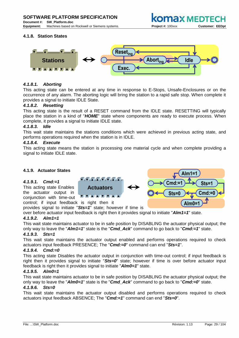
SOFTWARE PLATFORM SPECIFICATION Document #: SW_Platform.doc
Equipment: Machines based on Rockwell or Siemens systems. Project #: 100xxx Customer: EEDpt
File: ...\SW_Platform.doc Révision: 1.13 Page: 29 / 104
▼ ▼ ▲ ▲ ▼ ▼ ▲ ▲
Actuators
▼ ▼ ▲ ▲ ▼ ▼ ▲ ▲
Cmd:=1
Cmd:=0Sts=0
Alm1=1
Alm0=1
Sts=1Cmd:=1
Cmd:=0Sts=0
Alm1=1
Alm0=1
Sts=1Cmd:=1
Cmd:=0Sts=0
Alm1=1
Alm0=1
Sts=1
4.1.8. Station States
▼ ▲▼ ▲▼ ▲▼ ▲
Stations
▼ ▲▼ ▲ Reseting
Exec.
Aborting Idle
Reseting
Exec.
Aborting Idle
4.1.8.1. Aborting
This acting state can be entered at any time in response to E-Stops, Unsafe-Enclosures or on the occurrence of any alarm. The aborting logic will bring the station to a rapid safe stop. When complete it provides a signal to initiate IDLE State.
4.1.8.2. Resetting
This acting state is the result of a RESET command from the IDLE state. RESETTING will typically place the station in a kind of "HOME" state where components are ready to execute process. When complete, it provides a signal to initiate IDLE state.
4.1.8.3. Idle
This wait state maintains the stations conditions which were achieved in previous acting state, and performs operations required when the station is in IDLE.
4.1.8.4. Execute
This acting state means the station is processing one material cycle and when complete providing a signal to initiate IDLE state.
4.1.9. Actuator States
4.1.9.1. Cmd:=1
This acting state Enables the actuator output in conjunction with time-out control; if input feedback is right then it provides signal to initiate "Sts=1" state; however if time is over before actuator input feedback is right then it provides signal to initiate "Alm1=1" state.
4.1.9.2. Alm1=1
This wait state maintains actuator to be in safe position by DISABLING the actuator physical output; the only way to leave the "Alm1=1" state is the "Cmd_Ack" command to go back to "Cmd:=1" state.
4.1.9.3. Sts=1
This wait state maintains the actuator output enabled and performs operations required to check actuators input feedback PRESENCE; The "Cmd:=0" command can end "Sts=1".
4.1.9.4. Cmd:=0
This acting state Disables the actuator output in conjunction with time-out control; if input feedback is right then it provides signal to initiate "Sts=0" state; however if time is over before actuator input feedback is right then it provides signal to initiate "Alm0=1" state.
4.1.9.5. Alm0=1
This wait state maintains actuator to be in safe position by DISABLING the actuator physical output; the only way to leave the "Alm0=1" state is the "Cmd_Ack" command to go back to "Cmd:=0" state.
4.1.9.6. Sts=0
This wait state maintains the actuator output disabled and performs operations required to check actuators input feedback ABSENCE; The "Cmd:=1" command can end "Sts=0".

SOFTWARE PLATFORM SPECIFICATION Document #: SW_Platform.doc
Equipment: Machines based on Rockwell or Siemens systems. Project #: 100xxx Customer: EEDpt
File: ...\SW_Platform.doc Révision: 1.13 Page: 30 / 104
Programs(Machines, Stations, etc...)
Global
Local
Platform
4.2. UML's Models
4.2.1. Object Oriented
Structured Programming:
With this architecture most of the code instructions takes place in the so called "Platform"; most of this instructions are used in functions called by machines and stations programs; it is very difficult to delimit the data context so any test is painful; this architecture means big efforts to comply to any customer required exception with high risk in side effects; the worst constraint is the jarring to heterogeneous programs mix (multi sources providers direct integration).
Object Oriented Programming
The basic result of an object oriented software platform is the tremendous reduction of the code instructions used by the platform itself; most of the codes take place in objects directly instantiated in the machines or stations programs; it means light interdependence between programs and platform; it means easy customisation and heterogeneous programs mixing.
4.2.2. UML's Quatuor
The Komax SW_Platform complies with Object Oriented Programming principles in order to implement Gamp guide lines while ISA-S88 figures do not follow the standard UML guidelines; the following paragraphs depict SW_Platform with 4 UML perspectives:
The object diagram in UML is a diagram that shows a complete or partial view of the structure of a modelled system at a specific time.
The state diagram describes the behaviour of a programmed device or other process works such that an entity or each of its sub-entities are always in exactly one of a number of possible states and where there are well-defined conditional transitions between these states.
The sequence diagram is a kind of interaction diagram that shows how processes operate with one another and in what order. It is a construct of a Message Sequence Chart. A sequence diagram shows object interactions arranged in time sequence. It depicts the objects and class involved in the scenario and the sequence of messages exchanged between the objects needed to carry out the functionality of the scenario. Sequence diagrams typically are associated with use case realizations in the Logical View of the system under development.
The class diagram is the main building block in object oriented modelling. It is used both for general conceptual modelling of the systematic of the application and for detailed modelling translating the models into programming code. The classes in a class diagram represent both the main objects and/or interactions in the application and the objects to be programmed.
There are others UML's diagrams that could be used to depict software, but those four could make it.
Public
Private
Programs(Machines, Stations, etc...)
Platform

SOFTWARE PLATFORM SPECIFICATION Document #: SW_Platform.doc
Equipment: Machines based on Rockwell or Siemens systems. Project #: 100xxx Customer: EEDpt
File: ...\SW_Platform.doc Révision: 1.13 Page: 31 / 104
4.2.3. Objects Diagram
A machine is an aggregation of stations; and the stations are also aggregation of actuators.
Machine and stations contain the "Administration" data, while actuators do not.
Those "Administration" data are the machine "Public" commands, parameters, status, reports, statistics, accumulators, etc...
Those can be attached to tracks (machine side) and/or nests (on fixture side or conveyed pucks or pallets)
4.2.4. States Diagram
The m achine specific program only contains instructions to drive connected stations; so it only needs the same states as any stations programs.
The "Administration" program for a machine is driven by the machine states diagram that interacts with the "rest of the world" including the operator, see "Machine States" §5.1.7.
The stations programs could do their job with 3 acting states and 1 wait state; see "Station States" §5.1.8.
The actuators could do their job with 2 acting states and 4 wait states: see §5.1.9.
4.2.5. Sequential Diagram
Depending on the command "Exec" sent by the upper machine program, the station program initiates sequences that would send commands to relevant actuators, then switches to next sequence regarding actuators status, and so on to go through every defined sequence up to the completion of the current cycle that initiates the status "Idle".
_Mn_00_00 : Act _Mn_00_01 : Act _Mn_00_AA : Act
_Mn_01_00 : Act _Mn_01_01 : Act _Mn_01_AA : Act
_Mn_02_00 : Act _Mn_02_01 : Act _Mn_02_AA : Act
_Mn_Ss_00 : Act _Mn_Ss_01 : Act _Mn_SS_AA : Act
_Mn_00 : Station
_Mn_01 : Station
_Mn_02 : Station_Mn_02 : Station
_Mn_Ss : Station
_Mn_Machine
Admin
Admin
Admin
Admin
Admin
_Mn_AdminAdmin Admin
_Tracks _Nests
_Mn_SS : Station
_Mn_SS_00 : Act _Mn_SS_01 : Act _Mn_SS_AA : Act
_Mn_Machine
Sts_On
Cmd_On Cmd_Off
Cmd_On Cmd_On
Cmd_OffCmd_Off
ÊxecÊxec
Idle
Sts_Off
Sts_On Sts_On
Sts_OffSts_Off
_Mn_Xx : Station
_Mn_Ss_00 : Act _Mn_Ss_01 : Act _Mn_Ss_Aa : Act
_Mn_Machine
Aborting
Reseting
Idle
Exec.
Aborting
Reseting
Idle
Exec.
Aborting
Reseting
Idle
Exec.
Aborting
Reseting
Idle
Exec. Cmd_On
Cmd_Off
Sts_Off
Alm_On
Alm_Off
Sts_On
Cmd_On
Cmd_Off
Sts_Off
Alm_On
Alm_Off
Sts_On
_Mn_AdminSuspend
Stopped ExecuteStarting
Reseting Susping
Mo
des
Ch
ang
e
Held HoldingAborting
Idle
Stoping
Aborted
Suspend
Stopped ExecuteStarting
Reseting Susping
Mo
des
Ch
ang
e
Held HoldingAborting
Idle
Stoping
Aborted
Cmd_On
Cmd_Off
Sts_Off
Alm_On
Alm_Off
Sts_On
Cmd_On
Cmd_Off
Sts_Off
Alm_On
Alm_Off
Sts_On
Cmd_On
Cmd_Off
Sts_Off
Alm_On
Alm_Off
Sts_On
Cmd_On
Cmd_Off
Sts_Off
Alm_On
Alm_Off
Sts_On

SOFTWARE PLATFORM SPECIFICATION Document #: SW_Platform.doc
Equipment: Machines based on Rockwell or Siemens systems. Project #: 100xxx Customer: EEDpt
File: ...\SW_Platform.doc Révision: 1.13 Page: 32 / 104
4.2.6. Class Diagram
The result of the 3 previous analyses on objects, states and sequential diagrams is this class diagram.
Act_Cam
main classspecialization
Act_Cam
main classspecialization
Machine
0...0...
Act_Num
main classspecialization
Act_Num
main classspecialization
Act_Bin
main classspecialization
Act_Bin
main classspecialization
Act_Pls
main classspecialization
Act_Pls
main classspecialization
Act_AA Came0...
Act_AA Came0...
0...0...
Act_AA Numeric0...1
Act_AA Numeric0...1
Act_AA Binary0...
1...
Act_AA Binary0...
1...
Act_AA Pulse0...
Act_AA Pulse0...
specialization
specialization
main class
Man_Prog
specialization
specialization
main class
Man_Prog
main class
Man_Prog
main class
Man_Nest[Up]1...up
main class
Man_Nest[Up]1...up
1...
Station
1...
Station
main class
Man_Adm
1...main class
Man_Adm
1...
main class
Man_Track[Up]
1...up main class
Man_Track[Up]
main class
Man_Track[Up]
1...up
Typ_Batch
Interface
Typ_Recip
Interface
Typ_Batch
Interface
Typ_Recip
Interface
4.2.6.1. Hierarchy
Machine is an Admin(s), sub-machine(s) or station(s) aggregation.
Station is a sub-station(s) or actuator(s) aggregation.
Actuators are some main class specializations.
4.2.6.2. Specialization
Machine and Stations are "Mgr_Prog" and "Mgr_Adm" main class specialization.
Stations are "Mgr_Track" and "Mgr_Nest" main class specialization.
Actuators are "Act_xxx" main class specializations.
4.2.6.3. Main Class
Mgr_Adm is statistics and efficiency calculations for "oper", "shift" and "batch" real time OEE.
Mgr_Prog is states and sequences manager of any program (machine and station).
Mgr_Track is statistics and effectiveness calculations for track (track's real time OEE).
Mgr_Nest is statistics and effectiveness calculations for nest (nest's real time OEE).
Act_Bin is states control for binary component (cylinder, gate, conveyor, etc...)
Act_Cam is states control for camshaft component (angular axis, came follower, etc...)
Act_Num is states control for numeric component. (Linear axis, heater, flow meter, etc...)
Act_Pls is states control for hysteretic component. (Feeder level, flip-flop, tick control, etc...).
4.2.6.4. Interfaces
Typ_Recip is a user defined type for storing and restoring parameters and camshaft arrays.
Typ_Batch is a user defined type for manufacturing execution system to control multiple machines.

SOFTWARE PLATFORM SPECIFICATION Document #: SW_Platform.doc
Equipment: Machines based on Rockwell or Siemens systems. Project #: 100xxx Customer: EEDpt
File: ...\SW_Platform.doc Révision: 1.13 Page: 33 / 104
4.2.7. Class & Interfaces
4.2.7.1. Mgr_Adm
Manager for Statistics (Machine only); it includes logic to calculate real time OEE.
The tag naming conventions took place in §5.4.1.
Mgr_Prog, as reference to program manager.
Cfg_TrackQty, config. to define tracks quantity per station.
Cfg_OEEOff, config. to disable or reset rtOEE calculation.
Cmd_State, command to give current machine state.
Cmd_Sec, command to trig second pulse.
Rep_TmrTotal, report to view total time accumulation.
Rep_TmrExec, report to view operating time accumulation.
Rep_CtrBad, report to view aborting sequence quantity.
Rep_CtrTotal, report to view total sequence quantity.
Rep_CtrGood, report to view good sequence quantity.
Rep_Availability, report to view current OEE availability.
Rep_Performance, report to view current OEE performance.
Rep_Quality, report to view current OEE quality.
Rep_OEE, report to view current real time OEE value.
Sts_GoodID, status to indicate last execution was good (ID.0 for track #0, ID.1 for track #1, etc...).
Sts_BadID, status to indicate last execution was aborted (ID.0 for track #0, ID.1 for track #1, etc...).
...
Sample of an admin with "Oper", "Shift" and "Batch" defined.
Man_Adm
main class
Man_ProgPar_TimeIdealCfg_TrackQtyCfg_OEEOff Cmd_StateCmd_Sec
Rep_TmrTotalRep_TmrExecRep_CtrTotalRep_CtrGood
Sts_GoodIDSts_BadID
Rep_Avail.Rep_Perf.Rep_QlityRep_OEE

SOFTWARE PLATFORM SPECIFICATION Document #: SW_Platform.doc
Equipment: Machines based on Rockwell or Siemens systems. Project #: 100xxx Customer: EEDpt
File: ...\SW_Platform.doc Révision: 1.13 Page: 34 / 104
4.2.7.2. Mgr_Prog
Manager for Program (Machine or Station); it includes a states and a sequences logic.
The tag naming conventions took place in §5.4.1.
Cfg_Safe, config. is safe means module in safety conditions.
Cfg_ActExe, config. to enable actuators subroutine.
Cfg_Emulate, config. to enable emulation.
Cfg_SeqStep, config. to enable step-by-step sequences.
Par_TimeIdeal, parameter to define exec. ideal cycle time.
Cmd_SeqOns, command one shot under Step-by-Step.
Cmd_State, command to request state change:
o 1 = Abort
o 2 = Reset
o 4 = Exec
o n = Custom
Sts_State, status to indicate current state:
o 1 = Abort
o 2 = Reset
o 4 = Exec
o n = Custom
Sts_Seqp, status to indicate sequence previously executed.
Sts_Seq, status to indicate current sequence.
Sts_StateOns, status to indicate state change request.
Sts_SeqOns, status to indicate sequence change threshold.
Sts_SeqExe, status to indicate sequence is free to execute.
Sts_Emulate, status to indicate program under emulation mode.
Sts_NakAlm, status to indicate no alarm acknowledgement pending.
Sts_NoAlm, status to indicate no alarm pending.
Sts_dTing, status to indicate acting state not complete.
Sts_Abort, status to indicate abort is pending.
Sts_Safe, status to indicate sequence in safe mode.
Sts_Idle, status to indicate acting state complete.
Rep_dT, report to view acting state duration value.
...
Sample of a program defined.
Man_Prog
main class
Cfg_SafeCfg_ActExeCfg_EmulatePar_TimeIdealCmd_SeqOnsCfg_SeqStepCmd_State
Sts_StateSts_SeqpSts_Seq
Sts_StateOnsSts_SeqOnsSts_SeqExe
Sts_EmulateSts_NakAlmSts_NoAlmSts_dTingSts_Abort
Sts_SafeSts_IdleRep_dT

SOFTWARE PLATFORM SPECIFICATION Document #: SW_Platform.doc
Equipment: Machines based on Rockwell or Siemens systems. Project #: 100xxx Customer: EEDpt
File: ...\SW_Platform.doc Révision: 1.13 Page: 35 / 104
4.2.7.3. Mgr_Track
Manager for Tracks (Machine or Station); it includes logic to calculate real time OEE and consecutive errors test. The tag naming conventions took place in §5.4.1.
Mgr_Prog, as reference to program manager.
Par_MaxCons, parameter to define consecutive maximum.
Cfg_OEEOff, config. to disable or reset rtOEE calculation.
Cfg_ConsOff, ccnfig. to disable or reset consecutive test.
Rep_TmrAbort, report to view aborting time accumulation.
Rep_TmrExec, report to view executing time accumulation.
Rep_CtrBad, report to view aborting sequence quantity.
Rep_CtrGood, report to view good sequence quantity.
Rep_CtrExec, report to view executing sequence quantity.
Rep_Consec, report to view current consecutive value.
Rep_OEE, report to view current real time OEE value.
Sts_Enable, status to indicate current track is enable.
Sts_AlmCons, status to indicate consecutive alarm.
Sts_Good, status to indicate last execution was good.
Sts_Bad, status to indicate last execution was aborted.
...
Sample of a station with Track0 on Side0 and Track1 on Side1 defined.
Man_Track
main class
Man_ProgPar_MaxConsCfg_ConsOffCfg_OEEOff
Rep_TmrAbortRep_TmrExecRep_CtrGoodRep_CtrExecRep_CtrBad
Sts_EnableSts_AlmCons
Sts_GoodSts_Bad
Rep_ConsecRep_OEE
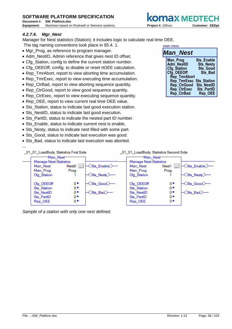
SOFTWARE PLATFORM SPECIFICATION Document #: SW_Platform.doc
Equipment: Machines based on Rockwell or Siemens systems. Project #: 100xxx Customer: EEDpt
File: ...\SW_Platform.doc Révision: 1.13 Page: 36 / 104
4.2.7.4. Mgr_Nest
Manager for Nest statistics (Station); it includes logic to calculate real time OEE.
The tag naming conventions took place in §5.4. 1.
Mgr_Prog, as reference to program manager.
Adm_NestID, Admin reference that gives nest ID offset.
Cfg_Station, config to define the current station number.
Cfg_OEEOff, config. to disable or reset rtOEE calculation.
Rep_TmrAbort, report to view aborting time accumulation.
Rep_TmrExec, report to view executing time accumulation.
Rep_CtrBad, report to view aborting sequence quantity.
Rep_CtrGood, report to view good sequence quantity.
Rep_CtrExec, report to view executing sequence quantity.
Rep_OEE, report to view current real time OEE value.
Sts_Station, status to indicate last good execution station.
Sts_NestID, status to indicate last good execution.
Sts_PartID, status to indicate the nested part ID number.
Sts_Enable, status to indicate current nest is enable.
Sts_Nesty, status to indicate nest filled with some part.
Sts_Good, status to indicate last execution was good.
Sts_Bad, status to indicate last execution was aborted.
...
Sample of a station with only one nest defined.
Man_Nest
main class
Man_ProgAdm_NestIDCfg_StationCfg_OEEOff
Rep_TmrAbortRep_TmrExecRep_CtrGoodRep_CtrExecRep_CtrBad
Sts_EnableSts_NestySts_Good
Sts_Bad
Sts_StationSts_NestIDSts_PartIDRep_OEE

SOFTWARE PLATFORM SPECIFICATION Document #: SW_Platform.doc
Equipment: Machines based on Rockwell or Siemens systems. Project #: 100xxx Customer: EEDpt
File: ...\SW_Platform.doc Révision: 1.13 Page: 37 / 104
4.2.7.5. Act_Bin
Act_Bin is states control for binary components (cylinder, gate, conveyor, etc...).
The tag naming conventions took place in §5.4.1.
Par_TimeOut, parameter to define movement timeout.
Cfg_Emulate, config. to enable or disable emulation.
Cfg_OEEOff, config. to disable or reset rtOEE calculation.
Cfg_NoAlm, config. to disable or enable alarming.
Cfg_Mirror, config. to make command mirroring input; Probe or Gauge behaviour instead of real active actuator.
Cmd_Nak, reverse command to acknowledge pending alarm.
Cmd_Ack, command to acknowledge pending alarm.
Cmd_Out, command to enable/disable output.
Cmd_Inp, command to read from physical input.
Rep_TmrExec, report to view acting state time accumulation.
Rep_CtrExec, report to view acting states quantity.
Rep_CtrAlm, report to view alarming states quantity.
Rep_OEE, report to view current real time OEE value.
Rep_dT, report to view movement duration value.
Sts_Alm0, status to indicate Alarm because of input not OFF
Sts_Alm1, status to indicate Alarm because of input not ON
Sts_Done, status to indicate time out over.
Sts_Out, status to indicate what should be send to physical output
Sts_Inp, status to indicate what is the status of physical input when not in emulation
...
Sample of a binary actuator specialization.
Act_Bin
main class
Par_TimeOutCfg_EmulateCfg_OEEOffCfg_NoAlmCfg_MirrorCmd_NakCmd_AckCmd_OutCmd_InpRep_TmrExecRep_CtrExecRep_CtrAlm
Sts_Alm0Sts_Alm1Sts_Done
Sts_OutSts_Inp
Rep_OEERep_dT

SOFTWARE PLATFORM SPECIFICATION Document #: SW_Platform.doc
Equipment: Machines based on Rockwell or Siemens systems. Project #: 100xxx Customer: EEDpt
File: ...\SW_Platform.doc Révision: 1.13 Page: 38 / 104
4.2.7.6. Act_Cam
Act_Cam is states control for camshaft components (angular axis, came follower, etc...).
The tag naming conventions took place in §5.4.1.
Par_TimeOut, parameter to define movement timeout.
Cfg_CamRng, config. to define the came range (360°).
Cfg_CamAnte, config. to define the angular value to anticipate.
Cfg_CamPost, config to define the angular value to postpone.
Cfg_SlowPar, config for slow timeout ratio vs normal timeout.
Cfg_Emulate, config. to enable or disable emulation.
Cfg_OEEOff, config. to disable or reset rtOEE calculation.
Cfg_NoAlm, config. to disable or enable alarming.
Cfg_Mirror, config. to make command mirroring input; Probe or came follower behaviour instead of real active actuator.
Cmd_Loop, command to request a full revolution cycle.
Cmd_Hold, command to request an immediate motion stop.
Cmd_Nak, reverse command to acknowledge pending alarm.
Cmd_Ack, command to acknowledge pending alarm.
Cmd_Out, command to set value for output.
Cmd_Sp, command to switch between different setpoints.
Cmd_Inn, command to read from physical input.
Rep_TmrExec, report to view acting state time accumulation.
Rep_CtrExec, report to view acting states quantity.
Rep_CtrAlm, report to view alarming states quantity.
Rep_Ante, report to indicate current anticipated window angle.
Rep_Post, report to indicate current postponed window angle.
Rep_OEE, report to view current real time OEE value.
Rep_dT, report to view movement duration value.
Sts_Alm0, status to indicate Alarm because of angular value still before CamAnte
Sts_Alm1, status to indicate Alarm because of angular value still after CamPost.
Sts_Done, status to indicate time out over.
Sts_Rev, status to indicate reverse motion.
Sts_Slow, status to indicate slow motion.
Sts_Out, status to indicate what should be send to physical output.
Sts_Inp, status to indicate the "in position" Boolean flag when not in emulation.
Sts_Inn, status to indicate the physical input value when not in emulation.
...
Sample of a camshaft follower specialization.
Act_Cam
main class
Par_TimeOutCfg_CamRngCfg_CamAnteCfg_CamPostCfg_SlowParCfg_EmulateCfg_OEEOffCfg_NoAlmCfg_MirrorCmd_LoopCmd_HoldCmd_NakCmd_AckCmd_OutCmd_SpCmd_Inn
Rep_TmrExecRep_CtrExecRep_CtrAlm
Sts_Alm0Sts_Alm1Sts_DoneSts_SlowSts_RevSts_OutSts_InpSts_Inn
Rep_AnteRep_PostRep_OEE
Rep_dT
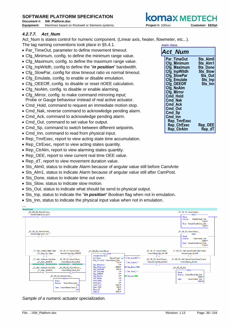
SOFTWARE PLATFORM SPECIFICATION Document #: SW_Platform.doc
Equipment: Machines based on Rockwell or Siemens systems. Project #: 100xxx Customer: EEDpt
File: ...\SW_Platform.doc Révision: 1.13 Page: 39 / 104
4.2.7.7. Act_Num
Act_Num is states control for numeric component. (Linear axis, heater, flowmeter, etc...).
The tag naming conventions took place in §5.4.1.
Par_TimeOut, parameter to define movement timeout.
Cfg_Minimum, config. to define the minimum range value.
Cfg_Maximum, config. to define the maximum range value.
Cfg_InpWitdh, config to define the "in position" bandwidth.
Cfg_SlowPar, config for slow timeout ratio vs normal timeout.
Cfg_Emulate, config. to enable or disable emulation.
Cfg_OEEOff, config. to disable or reset rtOEE calculation.
Cfg_NoAlm, config. to disable or enable alarming.
Cfg_Mirror, config. to make command mirroring input; Probe or Gauge behaviour instead of real active actuator.
Cmd_Hold, command to request an immediate motion stop.
Cmd_Nak, reverse command to acknowledge pending alarm.
Cmd_Ack, command to acknowledge pending alarm.
Cmd_Out, command to set value for output.
Cmd_Sp, command to switch between different setpoints.
Cmd_Inn, command to read from physical input.
Rep_TmrExec, report to view acting state time accumulation.
Rep_CtrExec, report to view acting states quantity.
Rep_CtrAlm, report to view alarming states quantity.
Rep_OEE, report to view current real time OEE value.
Rep_dT, report to view movement duration value.
Sts_Alm0, status to indicate Alarm because of angular value still before CamAnte
Sts_Alm1, status to indicate Alarm because of angular value still after CamPost.
Sts_Done, status to indicate time out over.
Sts_Slow, status to indicate slow motion.
Sts_Out, status to indicate what should be send to physical output.
Sts_Inp, status to indicate the "in position" Boolean flag when not in emulation.
Sts_Inn, status to indicate the physical input value when not in emulation.
...
Sample of a numeric actuator specialization.
Act_Num
main class
Par_TimeOutCfg_MinimumCfg_MaximumCfg_InpWitdhCfg_SlowParCfg_EmulateCfg_OEEOffCfg_NoAlmCfg_MirrorCmd_HoldCmd_NakCmd_AckCmd_OutCmd_SpCmd_Inn
Rep_TmrExecRep_CtrExecRep_CtrAlm
Sts_Alm0Sts_Alm1Sts_DoneSts_Slow
Sts_OutSts_InpSts_Inn
Rep_OEERep_dT
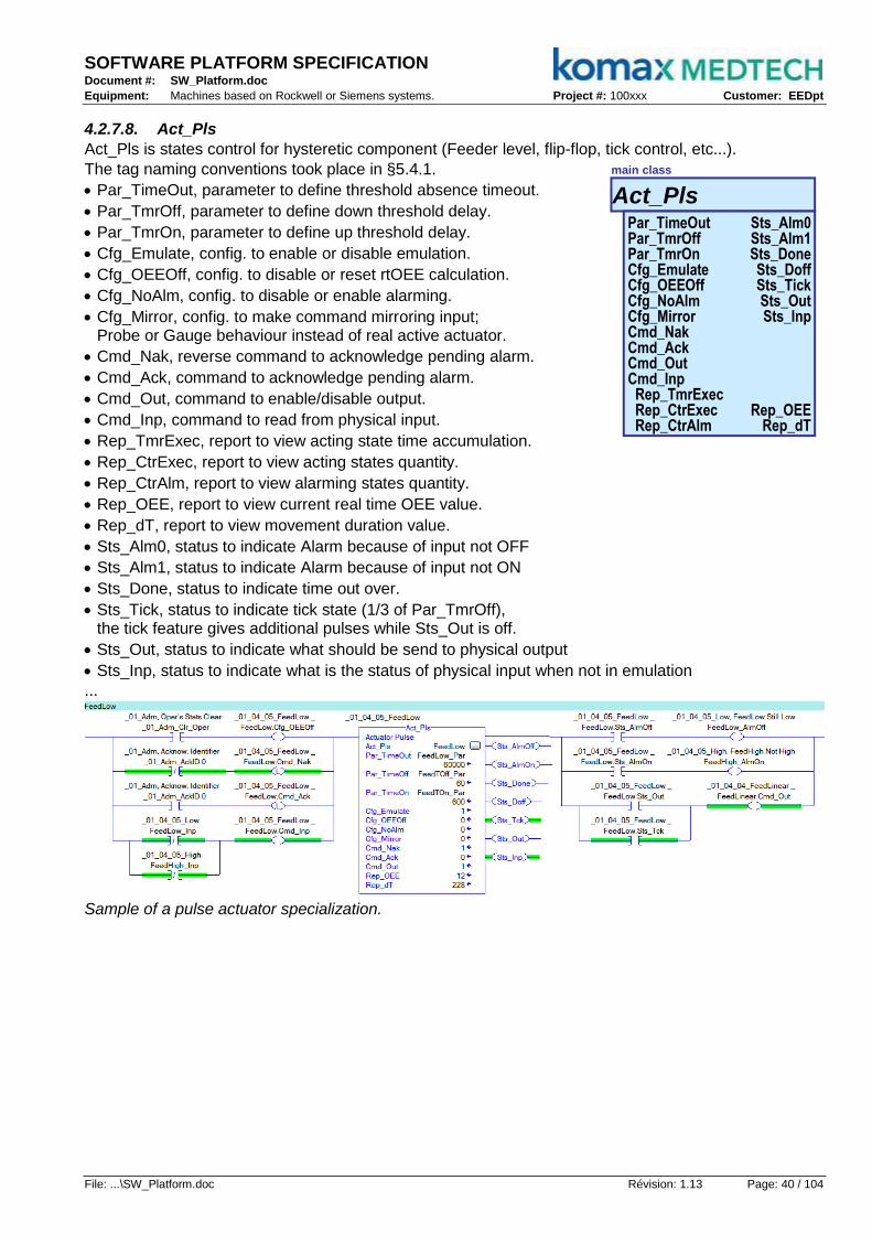
SOFTWARE PLATFORM SPECIFICATION Document #: SW_Platform.doc
Equipment: Machines based on Rockwell or Siemens systems. Project #: 100xxx Customer: EEDpt
File: ...\SW_Platform.doc Révision: 1.13 Page: 40 / 104
4.2.7.8. Act_Pls
Act_Pls is states control for hysteretic component (Feeder level, flip-flop, tick control, etc...).
The tag naming conventions took place in §5.4.1.
Par_TimeOut, parameter to define threshold absence timeout.
Par_TmrOff, parameter to define down threshold delay.
Par_TmrOn, parameter to define up threshold delay.
Cfg_Emulate, config. to enable or disable emulation.
Cfg_OEEOff, config. to disable or reset rtOEE calculation.
Cfg_NoAlm, config. to disable or enable alarming.
Cfg_Mirror, config. to make command mirroring input; Probe or Gauge behaviour instead of real active actuator.
Cmd_Nak, reverse command to acknowledge pending alarm.
Cmd_Ack, command to acknowledge pending alarm.
Cmd_Out, command to enable/disable output.
Cmd_Inp, command to read from physical input.
Rep_TmrExec, report to view acting state time accumulation.
Rep_CtrExec, report to view acting states quantity.
Rep_CtrAlm, report to view alarming states quantity.
Rep_OEE, report to view current real time OEE value.
Rep_dT, report to view movement duration value.
Sts_Alm0, status to indicate Alarm because of input not OFF
Sts_Alm1, status to indicate Alarm because of input not ON
Sts_Done, status to indicate time out over.
Sts_Tick, status to indicate tick state (1/3 of Par_TmrOff), the tick feature gives additional pulses while Sts_Out is off.
Sts_Out, status to indicate what should be send to physical output
Sts_Inp, status to indicate what is the status of physical input when not in emulation
...
Sample of a pulse actuator specialization.
Act_Pls
main class
Par_TimeOutPar_TmrOffPar_TmrOnCfg_EmulateCfg_OEEOffCfg_NoAlmCfg_MirrorCmd_NakCmd_AckCmd_OutCmd_InpRep_TmrExecRep_CtrExecRep_CtrAlm
Sts_Alm0Sts_Alm1Sts_DoneSts_DoffSts_TickSts_OutSts_Inp
Rep_OEERep_dT

SOFTWARE PLATFORM SPECIFICATION Document #: SW_Platform.doc
Equipment: Machines based on Rockwell or Siemens systems. Project #: 100xxx Customer: EEDpt
File: ...\SW_Platform.doc Révision: 1.13 Page: 41 / 104
Typ_Batch
interface
StoreID
DateProductDescript
MaterialID
AbortStopIdleExecHold
Typ_Recip
interface
RestoreStore
NamePars
Cams
4.2.7.9. Typ_Batch
User Defined Type for manufacturing execution system to control multiple machines.
Abort, request for quick end of batch.
Stop, request for clean end of batch.
Idle, request to activate batch and wait for confirmation from every machine.
Exec, request to enable batch after confirmation from every machine.
Hold, request for storing data and free machines before next exec request.
Store, container to memorize data that would be restored when restarting.
ID, batch ID.
Date, batch date.
Recipe, batch recipe.
Descript, batch description.
MaterialID, raw material ID.
Batch.Idle:=1
Batch.Exec:=1
BatchConf.Alm_Off = 1
Mach.Idle:=1
BatchConf.Cmd_On = 1Recipe Loaded
Mach.Hold:=1
BatchConf.Alm_On = 1
Mach.Exec:=1
BatchConf.Alm_On = 0BatchConf.Alm_Off = 0
Reset Count
Load Recips[ID]
Batch.Idle:=1
Batch.Exec:=1
BatchConf.Alm_Off = 1
Mach.Idle:=1
BatchConf.Cmd_On = 1Recipe Loaded
Mach.Hold:=1
BatchConf.Alm_On = 1
Mach.Exec:=1
BatchConf.Alm_On = 0BatchConf.Alm_Off = 0
Reset Count
Load Recips[ID]
Batch.Hold = 1Batch.Exec = 0
Mach.Hold:=1
Batch.Hold = 0Batch.Exec = 1
Mach.Exec:=1
Batch.Stop = 1 Batch.Abort = 1Batch.Idle = 0
Mach.Idle:=1
Store Count
Restore Count
Reset Count
Mach.Exec = 1
Mach. is free
Batch.Hold = 1Batch.Exec = 0
Batch.Hold = 1Batch.Exec = 0
Mach.Hold:=1
Batch.Hold = 0Batch.Exec = 1
Mach.Exec:=1
Batch.Stop = 1 Batch.Abort = 1Batch.Idle = 0
Mach.Idle:=1
Store Count
Restore Count
Reset Count
Mach.Exec = 1
Mach. is free
Batch.Hold = 1Batch.Exec = 0
4.2.7.10. Typ_Recipe
User Defined Type for storing and restoring parameters and camshaft arrays.
Restore, request to upload memorized parameters and camshafts.
Store, request to download and memorizing parameters and camshafts.
Name, recipe name.
Pars, container to memorize parameters array.
Cams, container to memorize camshaft array.
ID:=n
Recips[ID].Store = 1
Recips[ID] := ParamsRecips[ID].Store:=0
ID:=n
Recips[ID].Restore = 1
Params := Recips[ID]Recips[ID].Restore:=0

SOFTWARE PLATFORM SPECIFICATION Document #: SW_Platform.doc
Equipment: Machines based on Rockwell or Siemens systems. Project #: 100xxx Customer: EEDpt
File: ...\SW_Platform.doc Révision: 1.13 Page: 42 / 104
Typ_Nest
interface
Rep_TmrExecRep_CtrAbortRep_CtrGoodRep_CtrExec
Rep_OEESts_EnableSts_NestySts_AbortSts_Good
Sts_StationSts_NestIDSts_PartID
4.2.7.11. Typ_Nest
On this platform, there is no need for User Defined Type for nests "shift-register" or "Part-Info" data.
Rep_TmrExec, report to view executing time accumulation.
Rep_TmrAbort, report to view aborting time accumulation.
Rep_CtrGood, report to view good sequence quantity.
Rep_CtrExec, report to view executing sequence quantity.
Rep_CtrBad, report to view aborting sequence quantity.
Rep_OEE, report to view current real time OEE value.
Sts_Enable, status to indicate current nest is enable.
Sts_Nesty, status to indicate nest filled with some part.
Sts_Bad, status to indicate last execution was aborted.
Sts_Good, status to indicate las execution was good.
Sts_Station, status to indicate last good execution station.
Sts_NestID, status to indicate last good execution.
Sts_PartID, status to indicate the nested part ID number.
as it is required in structured programming where code and data are splitted:
Lookup[1]
_01_00 : Station_00
_01_01 : Station_01
_01_04 : Station_04
Shift Event
Shift Lookup
Update Reg.
Update Reg.
Nest[1]
Nest[2]
Nest[3]
Nest[4]
Nest[5]
Nest[6]
Nest[7]
Nest[8]
Lookup[2]
Lookup[3]
Lookup[4]
Lookup[5]
Lookup[6]
Lookup[7]
Lookup[8]
Nests Array
(Structure)
On this platform, a collection of nests object could reach the same goal without Typ_Nest.
Under Object Oriented Programming code and data are merged:
_01_00 : Station_00
_01_01 : Station_01
_01_04 : Station_04
Position Update
Station Event
Station Event
Nest[1]
Nest[2]
Nest[3]
Nest[4]
Nest[5]
Nest[6]
Nest[7]
Nest[8]

SOFTWARE PLATFORM SPECIFICATION Document #: SW_Platform.doc
Equipment: Machines based on Rockwell or Siemens systems. Project #: 100xxx Customer: EEDpt
File: ...\SW_Platform.doc Révision: 1.13 Page: 43 / 104
4.3. Embedded Features
The object oriented programming incites to integrate or to embed most often required features:
Efficiencies calculation.
Software emulation.
Fail safe feature.
Some other could be added in the future...
4.3.1. Real Time OEE for Ahead Diagnosis
Every SW_Platform components embed their own real time Overall Equipment Effectiveness calculation based on real time TR88 OEE normative reference. This feature lets user find out when the machine is low in efficiency, which station is involved and finally which actuator is making trouble; it helps more than making diagnosis from alarms messages waterfalls.
4.3.1.1. TR88 Theory
From ISA-TR88, Overall Equipment Effectiveness (OEE) is a measure comparing how well manufacturing equipment is running compared to the ideal plant. The resulting measurement is expressed as the ratio of the actual output of the equipment divided by the maximum possible output of the equipment under ideal conditions. OEE is calculated by multiplying three independently measured values: Availability, Performance Rate, and Quality Rate. The fundamental OEE definition is defined as an availability ratio multiplied by a performance ratio multiplied by a quality ratio.
OEE is often displayed as a waterfall object in which the major components of Availability, Performance, and Quality are displayed graphically. Losses are further subdivided into categories within the OEE sections.
Total Time
Scheduled Stops
Planed Production Time
Fault Stops
Operating Time
Suspending
Reduced Speed
Unscheduled Stops
Total Pieces Time Credit
Startup Rejects
Good Pieces Time Credit
Processed Rejects
Curtailment
Performance = Total Pieces / (Operating Time x Rate)
Availability = Operating Time / Planned Production Time
Quality = Good Pieces / Total Pieces
O E E = (Good_Pieces x 60) / (Planed_Production_Time x Machine_Rate_per_Min)
Calculating a Real-Time OEE in a Machine Controller or HMI
This example is a simple real-time calculation based upon Pack Tags with data originating from the machine controller. This example will not require historical tracking of information and will show a calculation of OEE since the last time the machine counts and timers were reset in the machine controller. This example is recommended for machine builders and control vendors that want to show a basic OEE on their HMI systems.
The limitation of this calculation will be that it will only be valid for the time period since the last time the counts and times were reset in the machine controller. It will also be invalid if the setup or product of the machine causes the design speed of the machine to change.
OEE = Availability x Performance x Quality
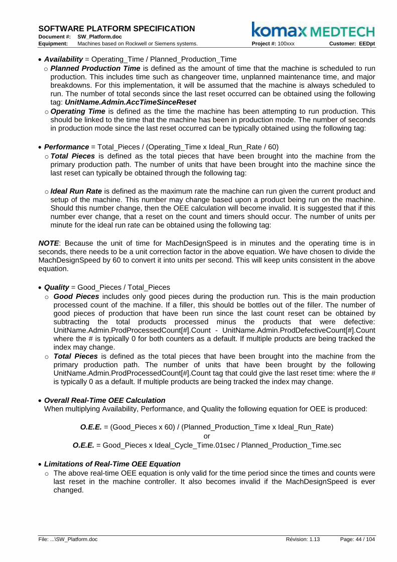
SOFTWARE PLATFORM SPECIFICATION Document #: SW_Platform.doc
Equipment: Machines based on Rockwell or Siemens systems. Project #: 100xxx Customer: EEDpt
File: ...\SW_Platform.doc Révision: 1.13 Page: 44 / 104
Availability = Operating_Time / Planned_Production_Time
o Planned Production Time is defined as the amount of time that the machine is scheduled to run production. This includes time such as changeover time, unplanned maintenance time, and major breakdowns. For this implementation, it will be assumed that the machine is always scheduled to run. The number of total seconds since the last reset occurred can be obtained using the following tag: UnitName.Admin.AccTimeSinceReset
o Operating Time is defined as the time the machine has been attempting to run production. This should be linked to the time that the machine has been in production mode. The number of seconds in production mode since the last reset occurred can be typically obtained using the following tag:
Performance = Total_Pieces / (Operating_Time x Ideal_Run_Rate / 60)
o Total Pieces is defined as the total pieces that have been brought into the machine from the primary production path. The number of units that have been brought into the machine since the last reset can typically be obtained through the following tag:
o Ideal Run Rate is defined as the maximum rate the machine can run given the current product and setup of the machine. This number may change based upon a product being run on the machine. Should this number change, then the OEE calculation will become invalid. It is suggested that if this number ever change, that a reset on the count and timers should occur. The number of units per minute for the ideal run rate can be obtained using the following tag:
NOTE: Because the unit of time for MachDesignSpeed is in minutes and the operating time is in seconds, there needs to be a unit correction factor in the above equation. We have chosen to divide the MachDesignSpeed by 60 to convert it into units per second. This will keep units consistent in the above equation.
Quality = Good_Pieces / Total_Pieces
o Good Pieces includes only good pieces during the production run. This is the main production processed count of the machine. If a filler, this should be bottles out of the filler. The number of good pieces of production that have been run since the last count reset can be obtained by subtracting the total products processed minus the products that were defective: UnitName.Admin.ProdProcessedCount[#].Count - UnitName.Admin.ProdDefectiveCount[#].Count where the # is typically 0 for both counters as a default. If multiple products are being tracked the index may change.
o Total Pieces is defined as the total pieces that have been brought into the machine from the primary production path. The number of units that have been brought by the following UnitName.Admin.ProdProcessedCount[#].Count tag that could give the last reset time: where the # is typically 0 as a default. If multiple products are being tracked the index may change.
Overall Real-Time OEE Calculation When multiplying Availability, Performance, and Quality the following equation for OEE is produced:
O.E.E. = (Good_Pieces x 60) / (Planned_Production_Time x Ideal_Run_Rate)
or
O.E.E. = Good_Pieces x Ideal_Cycle_Time.01sec / Planned_Production_Time.sec
Limitations of Real-Time OEE Equation
o The above real-time OEE equation is only valid for the time period since the times and counts were last reset in the machine controller. It also becomes invalid if the MachDesignSpeed is ever changed.

SOFTWARE PLATFORM SPECIFICATION Document #: SW_Platform.doc
Equipment: Machines based on Rockwell or Siemens systems. Project #: 100xxx Customer: EEDpt
File: ...\SW_Platform.doc Révision: 1.13 Page: 45 / 104
4.3.1.2. Mgr_Adm
With SW_Platform, the Mgr_Adm instances located in Admin program is in charge of machine OEE report. The following waterfall diagram shows where state elapsed times are putting in account.
Elapsed time since last clear
Operating Time
Aborting
Total Parts Time Credit
Good Parts Time Credit
Performance = Total Parts Time Credit / Op. Time
Availability = Operating Time / Accumulated Time since last reset
Quality = Good Parts / Total Parts
O E E = Good_Parts x Cycle_Time_Ideal_msec / Time_Since_Last_Clear_dsec
Aborted
Stopping
Stopped
Resetting
Idle
Suspending
Suspended
Starting
Bad Parts
Holding
Held
The upper formula only covers the machine effectiveness and is coded in Mgr_Adm class; this means by default, the effectiveness could be spread in "Oper", "Shift" or "Batch" or more instances. The Cycle_Time_Ideal is in msec and the Time_Since_Last_Clear is in dsec for result in %.
4.3.1.3. Mgr_Track
With SW_Platform, the Mgr_Track instances in station program are in charge of OEE report for one of the station track side. This formula covers station effectiveness and is embedded in Mgr_Track class.
O E E = (Ctr_Good x Cycle_Time_Ideal) / Tmr_Exec
4.3.1.4. Mgr_Nest
With SW_Platform, the Mgr_Nest instances in station program are in charge of OEE report for one of the fixture side. This formula covers nest effectiveness and is embedded in Mgr_Nest class.
O E E = (Ctr_Good / Ctr_Exec) x (1 - (Tmr_Abort / Tmr_Exec) )
4.3.1.5. Act_???
With SW_Platform, every Act_??? instance in actuators sub-programs are in charge of OEE report for each elementary module. This formula is embedded in Act_Bin, Act_Cam, Act_Num and Act_Pls class.
O E E = Time_Out x (Ctr_Exec - Ctr_Alarm) / Tmr_Exec
4.3.1.6. OEEs Supervision
The detailed real-time OEE at every level gives useful information to identify predictable failures. RSLinx Topic Name
SW_Platform
Tag Name Get Value Tag Name Get Value Tag Name Get Value Tag Name Get Value
Diagnostics Station 00 Effectivenenss Operator (User) Effectivenenss Shift Effectivenenss Batch
_01_00_Track.Rep_OEE 75 _01_Admin_Oper.Rep_TmrTotal 9674 _01_Admin_Shift.Rep_TmrTotal 9673 _01_Admin_Batch.Rep_TmrTotal 9672
_01_00_00_RotCam.Rep_OEE 189 _01_Admin_Oper.Rep_CtrTotal 2048 _01_Admin_Shift.Rep_CtrTotal 2048 _01_Admin_Batch.Rep_CtrTotal 2048
_01_00_01_Secu.Rep_OEE 116 _01_Admin_Oper.Rep_Availability 99 _01_Admin_Shift.Rep_Availability 99 _01_Admin_Batch.Rep_Availability 99
_01_00_02_Index.Rep_OEE 116 _01_Admin_Oper.Rep_Performance 106 _01_Admin_Shift.Rep_Performance 106 _01_Admin_Batch.Rep_Performance 106
_01_Admin_Oper.Rep_Quality 75 _01_Admin_Shift.Rep_Quality 75 _01_Admin_Batch.Rep_Quality 75
_01_Admin_Oper.Rep_OEE 78 _01_Admin_Shift.Rep_OEE 78 _01_Admin_Batch.Rep_OEE 78
Diagnostics Station 01 Diagnostics Station 02 Diagnostics Station 03 Diagnostics Station 04
_01_01_Track0.Rep_OEE 100 _01_02_Track0.Rep_OEE 75 _01_03_Track0.Rep_OEE 112 _01_04_Track0.Rep_OEE 88
_01_01_Track1.Rep_OEE 100 _01_02_Track1.Rep_OEE 75 _01_03_Track1.Rep_OEE 112 _01_04_Track1.Rep_OEE 88
_01_01_00_ArmGrip0.Rep_OEE 101 _01_02_00_ArmGrip0.Rep_OEE 101 _01_03_00_RotCam.Rep_OEE 199 _01_04_00_ArmGrip0.Rep_OEE 101
_01_01_01_ArmGrip1.Rep_OEE 101 _01_02_01_ArmGrip1.Rep_OEE 101 _01_03_01_Build0.Rep_OEE 101 _01_04_01_ArmGrip1.Rep_OEE 101
_01_01_02_ArmDown.Rep_OEE 101 _01_02_02_ArmDown.Rep_OEE 101 _01_03_02_Build1.Rep_OEE 101 _01_04_02_ArmDown.Rep_OEE 101
_01_01_03_ArmNum.Rep_OEE 168 _01_02_03_ArmNum.Rep_OEE 168 _01_03_03_Check0.Rep_OEE 101 _01_04_03_ArmNum.Rep_OEE 168
_01_01_04_BodyGate.Rep_OEE 101 _01_02_04_ScrewGate.Rep_OEE 101 _01_03_04_Check1.Rep_OEE 101 _01_04_04_PartConvoy.Rep_OEE 101
_01_01_05_BodyFeed.Rep_OEE 101 _01_02_05_ScrewFeed.Rep_OEE 101
Diagnostics Nest 01 Diagnostics Nest 02 Diagnostics Nest 03 Diagnostics Nest 04
_01_01_Nest0.Rep_OEE 100 _01_02_Nest0.Rep_OEE 45 _01_03_Nest0.Rep_OEE 100 _01_04_Nest0.Rep_OEE 100
_01_01_Nest1.Rep_OEE 100 _01_02_Nest1.Rep_OEE 100 _01_03_Nest1.Rep_OEE 100 _01_04_Nest1.Rep_OEE 44
_01_01_Nest0.Sts_PartID 0 _01_02_Nest0.Sts_PartID 2111 _01_03_Nest0.Sts_PartID 2109 _01_04_Nest0.Sts_PartID 2107
_01_01_Nest1.Sts_PartID 0 _01_02_Nest1.Sts_PartID 2112 _01_03_Nest1.Sts_PartID 2110 _01_04_Nest1.Sts_PartID 2108
24.01.2012SW_Platform DDE DiagnosticsKOMAX MEDTECH Set DiagGet Diag

SOFTWARE PLATFORM SPECIFICATION Document #: SW_Platform.doc
Equipment: Machines based on Rockwell or Siemens systems. Project #: 100xxx Customer: EEDpt
File: ...\SW_Platform.doc Révision: 1.13 Page: 46 / 104
4.3.2. Emulation for Early De-risking + Fail-Safe for Auto-recovery
Also use as "Fail Safe" feature due to its automatic and safe ability to compensate a failure.
4.3.2.1. Response Time
In signal processing, the impulse response of a dynamic system is its output when presented with an input command signal. More generally, an impulse response refers to the reaction of any dynamic system in response to some external change. In both cases, the impulse response describes the reaction of the system as a function of time (or possibly as a function of some other independent variable that parameterizes the dynamic behaviour of the system).
4.3.2.2. Principle
The SW_Platform integrates the emulation ability directly in the actuator functions; the concept is based on the "embedded time response" where the embedded timer is used to manage the movement time out while not being in emulation mode, or it is used to simulate the input feedback while being in emulation mode.
Additional benefits:
Automatic and safe ability to compensate a failure.
Simulate a part presence for "dry-cycle" purpose for instance.
4.3.2.3. Binary
See the top right sketch that applies to binary components such as cylinder, gate, conveyor, etc...
4.3.2.4. Came
Same as Numeric that applies to camshaft components such as angular axis came follower, etc...
4.3.2.5. Numeric
See the bottom right sketch that applies to numeric components such as linear axis, heater, flow-meter, etc...
4.3.2.6. Pulse
Same As Binary that applies to hysteretic components such as feeder level, flip-flop, tick control, etc...
dT►
╓╜dT►
╓╜ &
& &╖╙&╖╙
Cmd_Out
Sts_Alm
Sts_Inp
Sts_Out Cmd_InpCfg_Emulate
Sts_Done
Cmd_Ack
Cfg_NoAlm
0ff
On
t1 t2dT0ff
On
t1 t2dTOff
On
t1 t2dTOff
On
t1 t2dT
Cmd_On
Cmd_Off
Sts_Off
Alm_On
Alm_Off
Sts_On
Cmd_On
Cmd_Off
Sts_Off
Alm_On
Alm_Off
Sts_On
%T ►
╓╜%T ►
╓╜ &
Sts_Alm
Cmd_%Out Cmd_%InCfg_Emulate
Sts_Done
dT
Cmd_%Out
&
Sts_%InCmd_Ack
&╖╙&╖╙
Cfg_NoAlm
α
β
t1 t2%T2
min
max
t3 t4 t5
γ
%T3 %T4 %T5
α
β
t1 t2%T2
min
max
t3 t4 t5
γ
%T3 %T4 %T5Cmd_On
Cmd_Off
Sts_Off
Alm_On
Alm_Off
Sts_On
Cmd_On
Cmd_Off
Sts_Off
Alm_On
Alm_Off
Sts_On

SOFTWARE PLATFORM SPECIFICATION Document #: SW_Platform.doc
Equipment: Machines based on Rockwell or Siemens systems. Project #: 100xxx Customer: EEDpt
File: ...\SW_Platform.doc Révision: 1.13 Page: 47 / 104
4.3.3. Agility for Last Minute Changes
Agility in automation means a combination of specialization ability and flexible aggregation.
4.3.3.1. Double solenoid cylinder
▼▲
▼
▼
▼▼
▼▲ ▲▼
•Open
•Close
•Opened
•Closed
•OpenErr
•ClosErr
▼
▼
▲▼
▼▼
▼▲
▼
▼
▼▼
▼▲ ▲▼
•Open
•Close
•Opened
•Closed
•OpenErr
•ClosErr
▼
▼
▲▼
▼▼
4.3.3.2. Linear axis with limit switches
▼
▼
▼▲
▼
▼
▼▲
•Home
•Setpoint
•Homed
▲
▼
▼
▼
▼
▼
▼
•Getpoint
▲
▼
▼
▼▲
▼
▼
▼▲
•Home
•Setpoint
•Homed
▲
▼
▼
▼
▼
▼
▼
•Getpoint
▲
4.3.3.3. Rotary table
▼
▼
▼▲
▼
▼
▼ ▲
▲
▼
▼
▼▲
▼
▼ ▲▼
▼
▼
▼
▼
▼ ▲
•Start
•Stopped
▼
•Stopping
•Accelerate
•Cruise
•Indexing
•Indexed
•Index
▼
▼
▼▲
▼
▼
▼ ▲
▲
▼
▼
▼▲
▼
▼ ▲▼
▼
▼
▼
▼
▼ ▲
•Start
•Stopped
▼
•Stopping
•Accelerate
•Cruise
•Indexing
•Indexed
•Index

SOFTWARE PLATFORM SPECIFICATION Document #: SW_Platform.doc
Equipment: Machines based on Rockwell or Siemens systems. Project #: 100xxx Customer: EEDpt
File: ...\SW_Platform.doc Révision: 1.13 Page: 48 / 104
4.4. Configuration Conventions
Private definition (Program tags declaration) FunctionName_KeyCode_Description Ex: "Vision1_Cmd_Abort"
Public definition (Controller tags declaration) _Mn_Sn_Aa_PrivateDefinition (a public tag is a private tag + _Machine_Station_Actuator_ heading) Ex: "_11_26_01_Vision1_Cmd_Abort"
4.4.1. Keys Codes Meanings
Key Code Meaning Description Type(s)
4.4.1.1. Ack Acknowledge Used to send acknowledgement to instruction / function, typically used alarms acknowledgments.
DINT, BOOL
4.4.1.2. Act_ Actuator Used to specify an actuator instruction/function. Act_...
4.4.1.3. Adm, Admin
Administration Used at the machine level beside Cmd and Sts.
"Adm" is the short form of "Admin" that is the short form of "Administration.
Any
4.4.1.4. Alm Alarm Which alarm is occurring within process. This can be either a bit-level or value-level indication. Value-based alarm annunciation allows for a large quantity of alarms to be supported within a single indicator. Bit-level alarming can support multiple alarms simultaneously, but can require a large number of indicators to support all alarm states.
DINT, BOOL
4.4.1.5. Bin Binary Used to specify a binary actuator instruction/function
Act_Bin
4.4.1.6. Cam Camshaft Used to specify a camshaft actuator instruction / function
Act_Cam
4.4.1.7. Cfg Configuration Generally used to designate a value used in configuring how the process within the instruction / functions. This is only occasionally changed. It can be entered from the HMI or as part of a recipe or batch.
DINT, BOOL
4.4.1.8. Clr Clear Generally used to designate a command used to clear accumulators, report or parameters of the process within the instruction/functions.
DINT, BOOL
4.4.1.9. Cmd Command Generally used to as a command input of the instruction/function, either from the operator via the HMI or from the program.
DINT, BOOL
4.4.1.10. Ctl Control Complex PLC 's data structures used to control PLC's specific instruction/function.
CONTROL
4.4.1.11. Ctr Counter Used to accumulate or increment any value. DINT
4.4.1.12. ...ID Identifier Used to merge some Boolean status within an integer.
DINT
4.4.1.13. Inp Input Real-time data used to drive the process within an instruction / function. Generally used to designate a connection to a real input point or a control device (local or external).
DINT, BOOL
4.4.1.14. Log Login "User" User Login status of machine. DINT, BOOL
4.4.1.15. Mgr Manager Used to specify a manager instruction/function Mgr_...
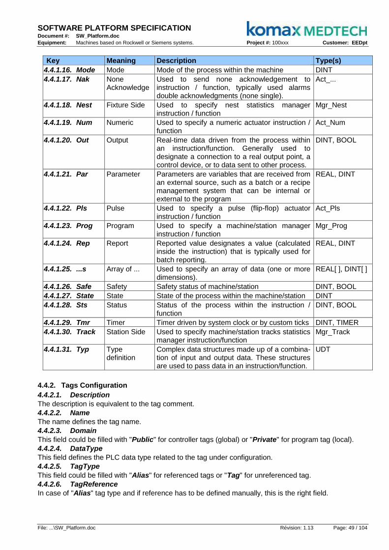
SOFTWARE PLATFORM SPECIFICATION Document #: SW_Platform.doc
Equipment: Machines based on Rockwell or Siemens systems. Project #: 100xxx Customer: EEDpt
File: ...\SW_Platform.doc Révision: 1.13 Page: 49 / 104
Key Meaning Description Type(s)
4.4.1.16. Mode Mode Mode of the process within the machine DINT
4.4.1.17. Nak None Acknowledge
Used to send none acknowledgement to instruction / function, typically used alarms double acknowledgments (none single).
Act_...
4.4.1.18. Nest Fixture Side Used to specify nest statistics manager instruction / function
Mgr_Nest
4.4.1.19. Num Numeric Used to specify a numeric actuator instruction / function
Act_Num
4.4.1.20. Out Output Real-time data driven from the process within an instruction/function. Generally used to designate a connection to a real output point, a control device, or to data sent to other process.
DINT, BOOL
4.4.1.21. Par Parameter Parameters are variables that are received from an external source, such as a batch or a recipe management system that can be internal or external to the program
REAL, DINT
4.4.1.22. Pls Pulse Used to specify a pulse (flip-flop) actuator instruction / function
Act_Pls
4.4.1.23. Prog Program Used to specify a machine/station manager instruction / function
Mgr_Prog
4.4.1.24. Rep Report Reported value designates a value (calculated inside the instruction) that is typically used for batch reporting.
REAL, DINT
4.4.1.25. ...s Array of ... Used to specify an array of data (one or more dimensions).
REAL[ ], DINT[ ]
4.4.1.26. Safe Safety Safety status of machine/station DINT, BOOL
4.4.1.27. State State State of the process within the machine/station DINT
4.4.1.28. Sts Status Status of the process within the instruction / function
DINT, BOOL
4.4.1.29. Tmr Timer Timer driven by system clock or by custom ticks DINT, TIMER
4.4.1.30. Track Station Side Used to specify machine/station tracks statistics manager instruction/function
Mgr_Track
4.4.1.31. Typ Type definition
Complex data structures made up of a combina-tion of input and output data. These structures are used to pass data in an instruction/function.
UDT
4.4.2. Tags Configuration
4.4.2.1. Description
The description is equivalent to the tag comment.
4.4.2.2. Name
The name defines the tag name.
4.4.2.3. Domain
This field could be filled with "Public" for controller tags (global) or "Private" for program tag (local).
4.4.2.4. DataType
This field defines the PLC data type related to the tag under configuration.
4.4.2.5. TagType
This field could be filled with "Alias" for referenced tags or "Tag" for unreferenced tag.
4.4.2.6. TagReference
In case of "Alias" tag type and if reference has to be defined manually, this is the right field.

SOFTWARE PLATFORM SPECIFICATION Document #: SW_Platform.doc
Equipment: Machines based on Rockwell or Siemens systems. Project #: 100xxx Customer: EEDpt
File: ...\SW_Platform.doc Révision: 1.13 Page: 50 / 104
4.4.3. Programs Names
In the controller main task, the programs names are related to their TR88 types.
4.4.3.1. Machine
_<Machine-ID>_<Machine-Name> (should be placed at the beginning of the task).
_<Machine-ID>_<Admin> (should be at the end of the task).
4.4.3.2. Station
_<Machine-ID>_<Station-ID>_<Station-Name>
4.4.3.3. Actuator
The Admin actuators are embedded in "Actuators_Sub" routine under "_Mn_Adm" programs.
4.4.4. Controller Tags
4.4.4.1. Admin
At the controller level, there are tags related to the TR88 Admin features; all off them belong to the machine and can be internally or remotely controlled.
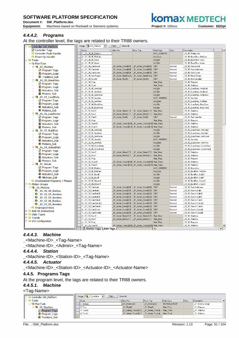
SOFTWARE PLATFORM SPECIFICATION Document #: SW_Platform.doc
Equipment: Machines based on Rockwell or Siemens systems. Project #: 100xxx Customer: EEDpt
File: ...\SW_Platform.doc Révision: 1.13 Page: 51 / 104
4.4.4.2. Programs
At the controller level, the tags are related to their TR88 owners.
4.4.4.3. Machine
_<Machine-ID>_<Tag-Name>
_<Machine-ID>_<Admin>_<Tag-Name>
4.4.4.4. Station
_<Machine-ID>_<Station-ID>_<Tag-Name>
4.4.4.5. Actuator
_<Machine-ID>_<Station-ID>_<Actuator-ID>_<Actuator-Name>
4.4.5. Programs Tags
At the program level, the tags are related to their TR88 owners.
4.4.5.1. Machine
<Tag-Name>

SOFTWARE PLATFORM SPECIFICATION Document #: SW_Platform.doc
Equipment: Machines based on Rockwell or Siemens systems. Project #: 100xxx Customer: EEDpt
File: ...\SW_Platform.doc Révision: 1.13 Page: 52 / 104
4.4.5.2. Station
<Tag-Name>
4.4.5.3. Actuator
<Actuator-Name>_<Actuator-subtag>
_<Alm0> means actuator not OFF
_<Alm1> means actuator not ON
_<Inp> means actuator physical input
_<Out> means actuator physical output
_<Par> means actuator parameter
_<Rep> means actuator report
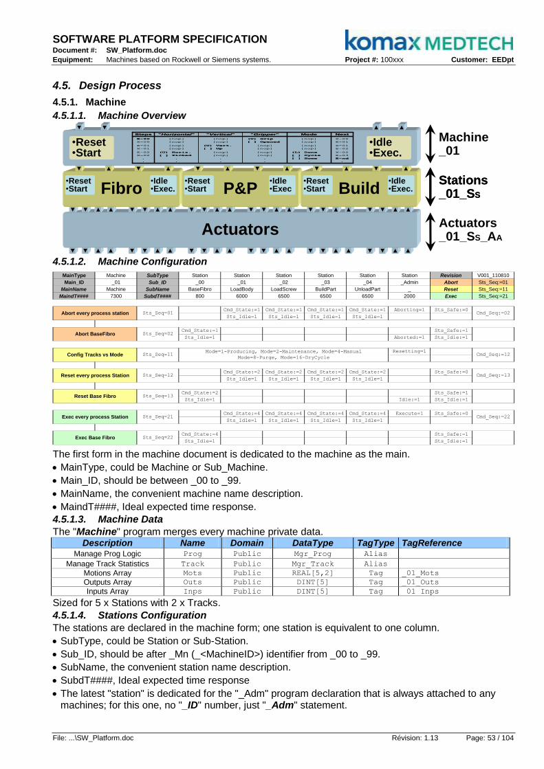
SOFTWARE PLATFORM SPECIFICATION Document #: SW_Platform.doc
Equipment: Machines based on Rockwell or Siemens systems. Project #: 100xxx Customer: EEDpt
File: ...\SW_Platform.doc Révision: 1.13 Page: 53 / 104
4.5. Design Process
4.5.1. Machine
4.5.1.1. Machine Overview
▼ ▼ ▲ ▲ ▼ ▼ ▲ ▲ ▼ ▼ ▲ ▲ ▼ ▼ ▲ ▲ ▼ ▼ ▲ ▲ ▼ ▼ ▲ ▲
Actuators
▼ ▼ ▲ ▲ ▼ ▼ ▲ ▲ ▼ ▼ ▲ ▲ ▼ ▼ ▲ ▲ ▼ ▼ ▲ ▲ ▼ ▼ ▲ ▲
Actuators_01_SS_AA
Stations_01_SS
Fibro
▼ ▲ ▼ ▲
P&P Build
▼ ▲ ▼ ▲ ▼ ▲ ▼ ▲
•Reset•Start
•Idle•Exec.
•Reset•Start
•Idle•Exec
•Reset•Start
•Idle•Exec.
Stations_01_SS
Fibro
▼ ▲ ▼ ▲
P&P Build
▼ ▲ ▼ ▲ ▼ ▲ ▼ ▲
•Reset•Start
•Idle•Exec.
•Reset•Start
•Idle•Exec
•Reset•Start
•Idle•Exec.
Machine_01
▼ ▲▼ ▲
•Reset•Start
•Idle•Exec.
X-00
E-01
X-01
E-02
X-02
E-03
E-nd
.
[nop]
[nop]
[nop]
[nop]
(L) Done
[ ] Cycle
[ ] Home
.
(U) Grip
[ ] Opened
[nop]
[nop]
[nop]
[nop]
.
.
[nop]
[nop]
(U) Vert.
[ ] Up
[nop]
[nop]
.
.
[nop]
[nop]
[nop]
[nop]
(U) Horiz.
[ ] Picked
.
.
E-00
X-00
E-01
X-01
E-02
X-02
.
.
NextMode"Gripper""Vertical""Horizontal"Steps
X-00
E-01
X-01
E-02
X-02
E-03
E-nd
.
[nop]
[nop]
[nop]
[nop]
(L) Done
[ ] Cycle
[ ] Home
.
(U) Grip
[ ] Opened
[nop]
[nop]
[nop]
[nop]
.
.
[nop]
[nop]
(U) Vert.
[ ] Up
[nop]
[nop]
.
.
[nop]
[nop]
[nop]
[nop]
(U) Horiz.
[ ] Picked
.
.
E-00
X-00
E-01
X-01
E-02
X-02
.
.
NextMode"Gripper""Vertical""Horizontal"Steps
4.5.1.2. Machine Configuration
MainType Machine SubType Station Station Station Station Station Station Revision V001_110810
Main_ID _01 Sub_ID _00 _01 _02 _03 _04 _Admin Abort Sts_Seq:=01
MainName Machine SubName BaseFibro LoadBody LoadScrew BuildPart UnloadPart _ Reset Sts_Seq:=11
MaindT#### 7300 SubdT#### 800 6000 6500 6500 6500 2000 Exec Sts_Seq:=21
Cmd_State:=1 Cmd_State:=1 Cmd_State:=1 Cmd_State:=1 Aborting=1 Sts_Safe:=0
Sts_Idle=1 Sts_Idle=1 Sts_Idle=1 Sts_Idle=1
Cmd_State:=1 Sts_Safe:=1
Sts_Idle=1 Aborted:=1 Sts_Idle:=1
Resetting=1
Cmd_State:=2 Cmd_State:=2 Cmd_State:=2 Cmd_State:=2 Sts_Safe:=0
Sts_Idle=1 Sts_Idle=1 Sts_Idle=1 Sts_Idle=1
Cmd_State:=2 Sts_Safe:=1
Sts_Idle=1 Idle:=1 Sts_Idle:=1
Cmd_State:=4 Cmd_State:=4 Cmd_State:=4 Cmd_State:=4 Execute=1 Sts_Safe:=0
Sts_Idle=1 Sts_Idle=1 Sts_Idle=1 Sts_Idle=1
Cmd_State:=4 Sts_Safe:=1
Sts_Idle=1 Sts_Idle:=1
Name Domain DataType TagType Ctrl+Shift+D = Double Click
Prog Public Man_Prog Alias Ctrl+Shift+S = Update Sheet
Track Public Man_Track Alias Ctrl+Shift+W = Update Workbook
Motions Public MOTION_GROUP Tag
Mots Public REAL[5,2] Tag
Outs Public DINT[5] Tag
Inps Public DINT[5] Tag
Outputs Array _01_Outs
Inputs Array _01_Inps
Motions Group _01_Motions
Motions Array _01_Mots
Mode=1-Producing, Mode=2-Maintenance, Mode=4-Manual
Mode=8-Purge, Mode=16-DryCycleSts_Seq=11 Cmd_Seq:=12
Reset every process Station
Reset Base Fibro Sts_Seq=13
Exec every process Station Sts_Seq=21 Cmd_Seq:=22
Exec Base Fibro Sts_Seq=22
Sts_Seq=12 Cmd_Seq:=13
Abort every process station Sts_Seq=01 Cmd_Seq:=02
Abort BaseFibro Sts_Seq=02
Config Tracks vs Mode
Manage Track Statistics
Description TagReference
Manage Prog Logic
The first form in the machine document is dedicated to the machine as the main.
MainType, could be Machine or Sub_Machine.
Main_ID, should be between _00 to _99.
MainName, the convenient machine name description.
MaindT####, Ideal expected time response.
4.5.1.3. Machine Data
The "Machine" program merges every machine private data. Description Name Domain DataType TagType TagReference
Manage Prog Logic Prog Public Mgr_Prog Alias
Manage Track Statistics Track Public Mgr_Track Alias
Motions Array Mots Public REAL[5,2] Tag _01_Mots
Outputs Array Outs Public DINT[5] Tag _01_Outs
Inputs Array Inps Public DINT[5] Tag _01_Inps
Sized for 5 x Stations with 2 x Tracks.
4.5.1.4. Stations Configuration
The stations are declared in the machine form; one station is equivalent to one column.
SubType, could be Station or Sub-Station.
Sub_ID, should be after _Mn (_<MachineID>) identifier from _00 to _99.
SubName, the convenient station name description.
SubdT####, Ideal expected time response
The latest "station" is dedicated for the "_Adm" program declaration that is always attached to any machines; for this one, no "_ID" number, just "_Adm" statement.

SOFTWARE PLATFORM SPECIFICATION Document #: SW_Platform.doc
Equipment: Machines based on Rockwell or Siemens systems. Project #: 100xxx Customer: EEDpt
File: ...\SW_Platform.doc Révision: 1.13 Page: 54 / 104
4.5.1.5. Admin Configuration
The "_Adm" program is always attached to a machine and "Administrate" as defined in TR88; the sequencer takes care of the machine state model, the operator panel buttons and the lights tree.
MainType Station SubType Act_Bin Act_Bin Act_Bin Act_Bin Act_Bin Act_Bin Act_Bin Act_Bin Revision V001_110810
Main_ID _01_Adm Sub_ID _00 _01 _02 _03 _04 _05 _06 _07 Abort n/a
MainName _ SubName SafeGuard Alm_Buzz Alm_White Alm_Green Alm_Amber Alm_Red But_Stop But_Start Reset n/a
MaindT#### 2000 SubdT#### 1000 1000 1000 1000 1000 1000 30 30 Exec n/a
Cmd_Out:=0 Cmd_Out:=0 Cmd_Out:=0 Flashing Flashing Flash if Alm Mach_Abort:=1 State:=01
Sts_Inp=0 AlmAbort=1 Sts_Inp=1 Mach_Idle=0
Cmd_Out:=0 Cmd_Out:=0 Cmd_Out:=0 Cmd_Out:=0 Steady Flashing Flash if Alm Sts_Safe:=00 State:=02
Sts_Inp=0 AlmAbort=1 Sts_Inp=0 Mach_Idle=1
Cmd_Out:=1 Cmd_Out:=0 Cmd_Out:=0 Flashing Cmd_Out:=0 Flashing Flash if Alm State:=03
Sts_Inp=1 AlmStop=1 Sts_Inp=1
Cmd_Out:=0 Cmd_Out:=0 Steady Cmd_Out:=0 Steady Flash if Alm Sts_Safe:=FF State:=04
Sts_Inp=1 AlmStop=1 Sts_Inp=0 Sts_Inp=0
State=04 Sts_Inp=0 Sts_Inp=1 Mach_Reset:=1 State:=05
Cmd_Out:=0 Flashing Flashing Cmd_Out:=0 Flashing Steady State:=06
AlmIdle=0 Mach_Idle=1
Cfg_NoAlm:=0 Cmd_Out:=0 Flashing Steady Cmd_Out:=0 Steady Flashing State:=07
Sts_Inp=1
Cmd_Out:=1 Cmd_Out:=0 Flashing Cmd_Out:=0 Cmd_Out:=0 Flashing Steady State:=06
Cfg_NoAlm=0 Sts_Inp=0
Sts_Inp=1 Sts_Inp=1 State:=08
Cfg_NoAlm:=1 Cmd_Out:=0 Steady Cmd_Out:=0 Cmd_Out:=0 Flashing Flash if Alm Mach_Exec:=1 State:=05
AlmIdle=1
AlmHold=1 State:=09
AlmSusp=1 State:=11
Flashing Steady Cmd_Out:=0 Cmd_Out:=0 Flashing Flash if Alm State:=10
Mach_Idle=1
Steady Flashing Cmd_Out:=0 Cmd_Out:=0 Flashing Flash if Alm State:=07
AlmHold=0
Flashing Cmd_Out:=0 Steady Cmd_Out:=0 Flashing Flash if Alm State:=12
Mach_Idle=1
Staedy Cmd_Out:=0 Flashing Cmd_Out:=0 Flashing Flash if Alm State:=07
AlmSusp=0Suspended, 12 State=12
Suspending, 11
State=09
State=11
State=07
Held, 10
State=08
Holding, 09
State=10
Aborting, 01State
Any
Stopping, 03
Execute, 08
Starting, 07
State=06
Aborted, 02
Stopped, 04
State=05
State
Any
Resetting, 05
Idle, 06
State
Any
State
Any
4.5.1.6. Admin Data
The "_Adm" program merges every machine public data
Description Name Domain DataType TagType TagReference Current State Sts_State Public DINT Tag _01_Adm_Sts_State
Command State Cmd_State Public DINT Tag _01_Adm_Cmd_State
Current Mode Sts_Mode Public DINT Tag _01_Adm_Sts_Mode
Command Mode Cmd_Mode Public DINT Tag _01_Adm_Cmd_Mode
Login Identifier LogID Public DINT Tag _01_Adm_LogID Safety Identifier SafeID Public DINT Tag _01_Adm_SafeID
Acknow. Identifier AckID Public DINT Tag _01_Adm_AckID
Alarms Identifier AlmID Public DINT Tag _01_Adm_AlmID
Alarm to Abort Alm_Abort Public BOOL Alias _01_Adm_AlmID.1
Alarm to Stop Alm_Stop Public BOOL Alias _01_Adm_AlmID.2
Alarm to Idle Alm_Idle Public BOOL Alias _01_Adm_AlmID.3
Alarm to Hold Alm_Hold Public BOOL Alias _01_Adm_AlmID.4
Alarm to Suspend Alm_Susp Public BOOL Alias _01_Adm_AlmID.5
Alarm to Warn Alm_Warn Public BOOL Alias _01_Adm_AlmID.6
Alarm to Help Alm_Help Public BOOL Alias _01_Adm_AlmID.7
Stats Clear Identifier ClrID Public DINT Tag _01_Adm_ClrID
Oper's Stats Clear Clr_Oper Public BOOL Alias _01_Adm_ClrID.0
Shift's Stats Clear Clr_Shift Public BOOL Alias _01_Adm_ClrID.1
Batch's Stats Clear Clr_Batch Public BOOL Alias _01_Adm_ClrID.2
Admin Array Adms Public Mgr_Adm[3] Tag _01_Adm_Adms
Admin Oper Adm_Oper Public Mgr_Adm Alias _01_Adm_Adms[0] Admin Shift Adm_Shift Public Mgr_Adm Alias _01_Adm_Adms[1] Admin Batch Adm_Batch Public Mgr_Adm Alias _01_Adm_Adms[2] Alarms Array Alms Public DINT[5,10] Tag _01_Adm_Alms
Camshafts Array Cams Public DINT[5,10] Tag _01_Adm_Cams
Parameters Array Pars Public DINT[5,10] Tag _01_Adm_Pars
Reports Array Reps Public DINT[5,10] Tag _01_Adm_Reps
Tracks Manager Tracks Public Mgr_Track[5,2] Tag _01_Adm_Tracks
Nests Manager Nests Public Mgr_Nest[5,2] Tag _01_Adm_Nests
Nests Empty NestEmpty Public DINT Tag _01_Adm_NestEmpty
Nest Identifier NestID Public DINT Tag _01_Adm_NestID
Part Identifier PartID Public DINT Tag _01_Adm_PartID
Pulse per Second PlsSec Public Act_Pls Tag _01_Adm_PlsSec
Motions Group Motions Public MOTION_GROUP Tag _01_Motions
Motions Array Mots Public REAL[5,2] Tag _01_Mots
Outputs Array Outs Public DINT[5] Tag _01_Outs
Inputs Array Inps Public DINT[5] Tag _01_Inps
Sized for 5 x Stations with 2 x Tracks.

SOFTWARE PLATFORM SPECIFICATION Document #: SW_Platform.doc
Equipment: Machines based on Rockwell or Siemens systems. Project #: 100xxx Customer: EEDpt
File: ...\SW_Platform.doc Révision: 1.13 Page: 55 / 104
Gri
pD
own
Req
uest
Pic
k-P
lace
Gri
pD
own
Req
uest
Pic
k-P
lace
4.5.2. Asynchronous Station
An asynchronous or transactional process individuates each of its activities so that each one commits its operation before execution continues.
4.5.2.1. Sample, Pick & Place
▼ ▼▲ ▲
Grip
▼ ▲ ▼ ▲
▼ ▼▲ ▲
Grip
▼ ▲ ▼ ▲
▼ ▼ ▲ ▲
Down
▼ ▲ ▼ ▲
▼▼▲ ▲ ▼ ▼ ▲ ▲
Pick
▼ ▲ ▼ ▲
Place
▼ ▲ ▼ ▲
▼▼▲ ▲ ▼ ▼ ▲ ▲
Pick
▼ ▲ ▼ ▲
Place
▼ ▲ ▼ ▲
Actuators_01_01_00_Grip
_01_01_01_Down
_01_01_02_P&P
P&P
▼ ▲▼ ▲
•Reset•Start
•Idle•Exec.
Station_01_01_Prog
Machine_01_Prog
▼ ▲▼ ▲
•Reset•Start
•Idle•Exec.
X-00
E-01
X-01
E-02
X-02
E-03
E-nd
.
[nop]
[nop]
[nop]
[nop]
(L) Done
[ ] Cycle
[ ] Home
.
(U) Grip
[ ] Opened
[nop]
[nop]
[nop]
[nop]
.
.
[nop]
[nop]
(U) Vert.
[ ] Up
[nop]
[nop]
.
.
[nop]
[nop]
[nop]
[nop]
(U) Horiz.
[ ] Picked
.
.
E-00
X-00
E-01
X-01
E-02
X-02
.
.
NextMode"Gripper""Vertical""Horizontal"Steps
X-00
E-01
X-01
E-02
X-02
E-03
E-nd
.
[nop]
[nop]
[nop]
[nop]
(L) Done
[ ] Cycle
[ ] Home
.
(U) Grip
[ ] Opened
[nop]
[nop]
[nop]
[nop]
.
.
[nop]
[nop]
(U) Vert.
[ ] Up
[nop]
[nop]
.
.
[nop]
[nop]
[nop]
[nop]
(U) Horiz.
[ ] Picked
.
.
E-00
X-00
E-01
X-01
E-02
X-02
.
.
NextMode"Gripper""Vertical""Horizontal"Steps
4.5.2.2. Horizontal Time Diagram Reference
4.5.2.3. Vertical Time Diagram with Transients Choices
4.5.2.4.

SOFTWARE PLATFORM SPECIFICATION Document #: SW_Platform.doc
Equipment: Machines based on Rockwell or Siemens systems. Project #: 100xxx Customer: EEDpt
File: ...\SW_Platform.doc Révision: 1.13 Page: 56 / 104
4.5.2.4. Transients to Matrix
_Seq:=01
_Seq:=02
_Seq:=03
_Seq:=04
_Seq:=05
_Seq:=06
_Seq:=07
_Seq:=08
_Seq:=00
Request=1
Request:=0
Place:=1
Place=1
Pick:=1
Pick=1
Down:=1
Down=1
Down:=0
Down=0
Down:=1
Down=1
Down:=0
Down=0
Grip:=1
Grip=1
Grip:=0
Grip=0
_Seq=00
_Seq=01
_Seq=02
_Sep=03
_Seq=04
_Seq=05
_Seq=06
_Seq=07
_Seq=08
Cmd_RequestPick-PlaceDownGripSts_
"Sts_Seq=nn" if Sequence number "nn"
"Actuator:=1" Set Act.Cmd_Out to ON
"Actuator=1" if Act.Sts_Inp is ON
"Cmd_Seq:=nn" Set Sequence number to "nn"
"Actuator:=0" Set Act.Cmd_Out to OFF
"Actuator=0" if Act.Sts_Inp is OFF
4.5.2.5. Station Configuration
Type, Prog.. Type
##, Program ID Nbr
Name, Description
dT####, Exp. time Out
Type, Actuator Type
##, Actuator ID Nbr
Name, Description
dT####, Exp. time Out
Cm
d_S
eq
:=xx
Next
sequence
Date, Year-Month-Day
Version, Revision number
Reset,
Seq.
for
rese
ttin
g
Ho
me,
Seq.
for
hom
ing
Cycle
, S
eq.
for
cyclin
g
Request
Station versus
sequence
Module #00
activity versus
sequence
Module #01
activity versus
sequence
Module #02
activity versus
sequence
Sts_Seq=xx
Current
sequence
sequence
description

SOFTWARE PLATFORM SPECIFICATION Document #: SW_Platform.doc
Equipment: Machines based on Rockwell or Siemens systems. Project #: 100xxx Customer: EEDpt
File: ...\SW_Platform.doc Révision: 1.13 Page: 57 / 104
4.5.2.6. Station Sequencer
Header = Manager of Program LogicHeader = Manager of Program Logic
4.5.2.7. Sequences Details
The sequence branch start with the test on the current sequence value.
Then it is splitted in two branches:
o The first one is conditioned by "Prog.Sts_SeqOns" that gives the up threshold and where the commands to the actuators take place.
o The second one is conditioned by "Prog.Sts_SeqExe" that enable the sequence to be executed and where the status from the actuators are tested.
At the right, if the second half branch conditions are all good, then the command to next sequence is written with some other station instructions such as "Prog.Sts_Safe" for instance.
4.5.2.8. Tags List
With the spreadsheet embedded macro, every station tag is merged in the tags list form.
MainType Machine Revision V001_110810
Main_ID _01 Made Komax
MainName Machine by SW
Scope _ID Name Domain DataType TagType TagReference Description
T a g s L i s t
_01_01_LoadBody _01_01_ArmAxis ArmAxis Public AXIS_GENERIC Tag _01_01_03_ArmAxis _01_01, Arm Axis
_01_01_LoadBody _01_01_ArmAxisCtl ArmAxisCtl Private MOTION_INSTRUCTION[10] Tag _01_01, Arm Axis Control
_01_01_LoadBody _01_01_ArmAxisSts ArmAxisSts Private DINT Tag _01_01, Arm Axis Status
_01_01_LoadBody _01_01_Nest0 Nest0 Public Man_Nest Alias _01_Admin_Nests[1,0] _01_01, Statistics
_01_01_LoadBody _01_01_Nest1 Nest1 Public Man_Nest Alias _01_Admin_Nests[1,1] _01_01, Statistics
_01_01_LoadBody _01_01_Prog Prog Public Man_Prog Alias _01_01, Program
_01_01_LoadBody _01_01_Track0 Track0 Public Man_Track Alias _01_Admin_Tracks[1,0] _01_01, Statistics
_01_01_LoadBody _01_01_Track1 Track1 Public Man_Track Alias _01_Admin_Tracks[1,1] _01_01, Statistics
_01_02_LoadScrew _01_02_ArmAxis ArmAxis Public AXIS_GENERIC Tag _01_02_03_ArmAxis _01_02, Arm Axis

SOFTWARE PLATFORM SPECIFICATION Document #: SW_Platform.doc
Equipment: Machines based on Rockwell or Siemens systems. Project #: 100xxx Customer: EEDpt
File: ...\SW_Platform.doc Révision: 1.13 Page: 58 / 104
4.5.3. Synchronous Station
A synchronous process is invoked by a request based on camshaft angle.
4.5.3.1. Sample, Build & Check Time Diagram Reference
4.5.3.2. Vertical Time Diagram with Transients
4.5.3.3. Transients to Matrix
_Seq:=01
_Seq:=02
_Seq:=03
_Seq:=04
_Seq:=05
_Seq:=06
_Seq:=00
Request=1
Request:=0
Cmd_Out:=0
Sts_Inp=0
Cmd_Out:=1
Cmd_Out:=0
Sts_Inp=0
Cmd_Out:=0
Sts_Inp=0
Cmd_Out:=1
Cmd_Out:=0
Sts_Inp=0
Cmd_Out:=330
Rep_Ante≥060
Rep_Ante≥180
Rep_Ante≥270
Rep_Ante≥330
Cmd_Out:=000
_Seq=00
_Seq=01
_Seq=02
_Sep=03
_Seq=04
_Seq=05
_Seq=06
Cmd_RequestCheckBuildCamShaftSts_
"Sts_Seq=nn" if Sequence number "nn"
"Actuator:=1" Set Act.Cmd_Out to ON
"Actuator=1" if Act.Sts_Inp is ON
"Cmd_Seq:=nn" Set Sequence number to "nn"
"Actuator:=0" Set Act.Cmd_Out to OFF
"Actuator=0" if Act.Sts_Inp is OFF
Ca
ms
ha
ftB
uil
dR
eq
uest
Ch
ec
k
000°
060°
180°
270°
000°
330°
Camshaft Build RequestCheck

SOFTWARE PLATFORM SPECIFICATION Document #: SW_Platform.doc
Equipment: Machines based on Rockwell or Siemens systems. Project #: 100xxx Customer: EEDpt
File: ...\SW_Platform.doc Révision: 1.13 Page: 59 / 104
4.5.3.4. Station Configuration Type, Prog.. Type
##, Program ID Nbr
Name, Description
dT####, Exp. time Out
Type, Actuator Type
##, Actuator ID Nbr
Name, Description
dT####, Exp. time Out
Date, Year-Month-Day
Version, Revision number
Request
Station versus
sequence
Module #00
activity versus
sequence
Module #01
activity versus
sequence
Module #02
activity versus
sequence
Sts_Seq=xx
Current
sequence
sequence
description
MainType Station SubType Act_Cam Act_Bin Act_Bin Revision V001_110810
Main_ID _01_03 Sub_ID _00 _01 _02 Abort Sts_Seq:=01
MainName BuildPart SubName RotCam Build0 Check0 Reset Sts_Seq:=01
MaindT#### 10000 SubdT#### 9000 1000 1000 Exec Sts_Seq:=02
Cmd_Out:=0 Cmd_Out:=0
Sts_Inp=0 Sts_Inp=0
Sts_Seq=02 Cmd_Out:=330 Sts_Safe:=0 Cmd_Seq:=03
Sts_Seq=03 Rep_Ante≥090 Cmd_Out:=1 Cmd_Seq:=04
Sts_Seq=04 Rep_Ante≥190 Cmd_Out:=1 Cmd_Seq:=05
Cmd_Out:=0 Cmd_Out:=0
Sts_Inp=0 Sts_Inp=0 Sts_Safe:=1
Rep_Ante≥330
Cmd_Out:=000Sts_Seq=06
Disable Builds
Disable ChecksSts_Seq=01 Cmd_Seq:=06
Sts_Idle:=1
Disable All Sts_Seq=05 Rep_Ante≥270
Cam Exec
Enable Build
Enable Check
Cmd_Seq:=06
Cam Up
4.5.3.5. Station Sequencer
Header = Manager of Program LogicREQUEST WAIT
CAM UP
DISABLE BUILD
DISABLE CHECK
DISABLE BUILD
DISABLE CHECK
CAM EXEC
ENABLE BUILD
ENABLE CHECK
Cam Exec
Enable Build
Enable Check
Cam Up
Disable Builds
Disable Checks
Disable All
Cam Exec
Enable Build
Enable Check
Cam Up
Disable Builds
Disable Checks
Disable All
Cam Exec
Enable Build
Enable Check
Cam Up
Disable Builds
Disable Checks
Disable All
4.5.3.6. Sequences Details
Header rungs exactly the same codes between synchronous and asynchronous.
The synchronous sequence (#2 for instance) starts by defining the came setpoint (330° for instance). Then each rung uses a "LIM" instruction that checks if predefined angle is between "_CamAnte" and "_CamPost". The last "camshafted" rung checks reached last angle to request the next sequence #3.
4.5.3.7. Tag List
As Asynchronous station...

SOFTWARE PLATFORM SPECIFICATION Document #: SW_Platform.doc
Equipment: Machines based on Rockwell or Siemens systems. Project #: 100xxx Customer: EEDpt
File: ...\SW_Platform.doc Révision: 1.13 Page: 60 / 104
4.5.4. Actuator
4.5.4.1. Configuration
The actuators are declared in the station form; one actuator is equivalent to one column.
SubType, could be Act_Bin, Act_Cam, Act_Num or Act_Pls.
Sub_ID, should be after _Mn_Ss (_<MachineID>_<StationID>) identifier from _00 to _99.
SubName, the convenient function name description.
SubdT####, Ideal expected time response
4.5.4.2. Actuators List
With the spreadsheet embedded macro, every station actuator are merged in the actuators list form where definitions extensions could added such as physical output / inputs, parameters or reports.
Scope, should be the name of the program where the actuator take place.
_ID, should be the actuator ID seen from the controller point of view (_Mn_Ss_Aa means _<MachineID>_<StationID>_<ActuatorID>).
Name, the convenient function name description.
DataType, could be Act_Bin, Act_Cam, Act_Num, Act_Pls or Alias
DataValue, expected time response or any additional parameter value.
Parameter Definition, Admin reference that gives ID number in parameters array.
Parameter Description, the text to add after _Mn_Ss_Aa_Name...
Report Definition, Admin reference that gives ID number in repoerts array.
Report Description, the text to add after _Mn_Ss_Aa_Name...
Alarm OFF Definition, Admin reference that gives ID number in alarms array.
Alarm OFF Description, the text to add after _Mn_Ss_Aa_Name...
Alarm ON Definition, Admin reference that gives ID number in alarms array.
Alarm ON Description, the text to add after _Mn_Ss_Aa_Name...
Output Definition, Physical reference that gives ID number in outputs array.
Input Definition, Physical reference that gives ID number in inputs array.
...

SOFTWARE PLATFORM SPECIFICATION Document #: SW_Platform.doc
Equipment: Machines based on Rockwell or Siemens systems. Project #: 100xxx Customer: EEDpt
File: ...\SW_Platform.doc Révision: 1.13 Page: 61 / 104
4.5.4.3. Programming
4.5.5. Design Workflow
HDS.doc
SDS.doc
Install.IQ
Perf.PQ
Alpha
or Beta
Alpha
or Beta
Release
Candidate
Release
Candidate
Gold
Release
Gold
Release
Imagine Achieve Check
HDS.doc
Oper..OQ
SDS.doc
FDS.doc
URS.doc
SDS.doc
HDS.doc Draw
.dwg
FDS.doc
Diag..xls.xls
Conf.Diag..xls.xls
Conf.
.drwDraw
Code.plc
Test.xls.plc
Code.xls
Test
Test.xls.drw
Wire
Test.xls.dwg
MountSupply.doc
Design.dwg
FDS.doc
N°
Test.xls
.doc
User's
Guide
N°

SOFTWARE PLATFORM SPECIFICATION Document #: SW_Platform.doc
Equipment: Machines based on Rockwell or Siemens systems. Project #: 100xxx Customer: EEDpt
File: ...\SW_Platform.doc Révision: 1.13 Page: 62 / 104
5. Hardware Interfaces
5.1. Topology
There is no automation software without hardware; this document gives a typical topology that complies with machine directive 2006/42/CE (ISO 13849-1).
5.1.1. Physical Interface
Clean Air
Safe
Actuators
Unsafe Cylinders
Safe Cylinders
Unsafe
Actuators
Main Switch
E-Stop
Light
Curtain
Safety Stop
MainValve
Safety Switches
Safety Servo
SafetyValve
Safety Speed
5 / 3 Valves
5 / 2Valves
Door
Key
5.1.2. Human Interface

SOFTWARE PLATFORM SPECIFICATION Document #: SW_Platform.doc
Equipment: Machines based on Rockwell or Siemens systems. Project #: 100xxx Customer: EEDpt
File: ...\SW_Platform.doc Révision: 1.13 Page: 63 / 104
5.2. Components
It proposes a classified list of standard components that could be used with this platform and how to drive them from a software point of view.
Designation Supplier Reference
Power supply MOELLER ELECTRIC SN3-100-EU8
E-Stop luminous. Head MOELLER ELECTRIC M22-PVLT
E-Stop Block Contact MOELLER ELECTRIC M22-CK01
E-Stop Led MOELLER ELECTRIC M22-CLED-R
Door Switch SIEMENS 3SE5322-0SBS1 / 24VDC
Safety Security Unit PILZ PNOZ E1.1P
Safety Contactor ROCKWELL 100S*
Drive controller BOSCH REXROTH HCS02.1E-W0070-A-03-NNNN
Board basic single-axis BOSCH REXROTH CSB01.1C-PB-ENS-EN1-NN-S-NN-FW
Motor cable BOSCH REXROTH IKG4118/005.0
Encoder cable BOSCH REXROTH IKS4042/005.0
Multi-axis Servo Drive ROCKWELL Kinetix 6500*
Control module Ethernet IP ROCKWELL 2094-EN02D-M01-S1
Ethernet cable ROCKWELL 1595J-M8CBJM-x
Ethernet cable / 0.3m ROCKWELL 1585J-M8CBJM-0M3
Vision camera COGNEX In-sight
2D Matrix readers COGNEX To be defined
Bar code guns DATALOGIC DS2100N-1214
Optic Sensors KEYENCE To be defined
Cylinder Sensors BALLUF To be defined
Inductive Sensors CONTRINEX To be defined
Optic Sensors BAUMER To be defined
Cylinder Sensors FESTO To be defined
Single Solenoid Valve (360 l/min) FESTO VMPA1-M1H-M-PI
Double Solenoid Valve (360 l/min) FESTO VMPA1-M1H-J-PI
Centre Closed Solenoid Valve (320 l/min) FESTO VMPA1-M1H-G-PI
Centre Exhaust Solenoid Valve (240 l/min) FESTO VMPA1-M1H-E-PI
Vacuum Solenoid Valve (200 l/min) FESTO MHE3-M1H-3/2G-1/8
Vacuum Solenoid Valve (900 l/min) FESTO CPE14-M1BH-3GLS-1/8
Head BP bright white MOELLER ELECTRIC M22-DL-W
Head BP bright green MOELLER ELECTRIC M22-DL-G
Head BP bright blue MOELLER ELECTRIC M22-DL-B
Head BP bright red MOELLER ELECTRIC M22-DL-R
Head BP bright yellow MOELLER ELECTRIC M22-DL-Y
Module led white MOELLER ELECTRIC M22-CLEDC-W or M22-CLED-W
Module led green MOELLER ELECTRIC M22-CLEDC-G or M22-CLED-G
Module led blue MOELLER ELECTRIC M22-CLEDC-B or M22-CLED-B
Module led red MOELLER ELECTRIC M22-CLEDC-R or M22-CLED-R
Block contact NC MOELLER ELECTRIC M22-CK01 or M22-CKC01
Block contact NO MOELLER ELECTRIC M22-CK10 or M22-CKC10
Red Light MOELLER ELECTRIC SL-L-R & SL-LED-R
Amber Light MOELLER ELECTRIC SL-L-Y & SL-LED-Y
Green Light MOELLER ELECTRIC SL-L-G & SL-LED-G
White Light MOELLER ELECTRIC SL-L-W & SL-LED-W
Buzzer MOELLER ELECTRIC SL-A24
...
...

SOFTWARE PLATFORM SPECIFICATION Document #: SW_Platform.doc
Equipment: Machines based on Rockwell or Siemens systems. Project #: 100xxx Customer: EEDpt
File: ...\SW_Platform.doc Révision: 1.13 Page: 64 / 104
5.3. Operator Panel
°°
StopStop StartStart Jog -Jog - Jog +Jog +
5.3.1. E-Stop
Anytime, this button requests machine state "Aborting".
Then when machine state is "Aborted", the doors are unlocked.
5.3.2. Stop
If machine state is "Stopped", this button requests machine state "Aborting".
If machine state is different than "Stopped", this button requests machine state "Stopping".
Then when machine state is "Stopped", the doors are locked.
5.3.3. Start
If machine state is "Stopped", this button requests machine state "Resetting".
Then when machine state is "Idle", this button requests machine state "Starting".
If machine state keeps "Starting" for 2 seconds, then machine state goes to "Execute".
Anytime, the button requests an acknowledgement on pending alarm(s).
5.3.4. Jog -
If machine mode is "Manual", this button requests a negative slow motion on selected axis.
5.3.5. Jog +
If machine mode is "Manual", this button requests a positive slow motion on selected axis.
5.4. Lights
Machine States vs
Lights States
Ab
ort
ing
Ab
ort
ed
Sto
pp
ing
Sto
pp
ed
Re
sett
ing
Idle
Sta
rtin
g
Exe
cute
Ho
ldin
g
He
ld
Su
spe
nd
ing
Su
spe
nd
ed
5.4.1. Red Light Flashing F F F
5.4.2. Red Light Steady S S S
5.4.3. Amber Light Flashing F F
5.4.4. Amber Light Steady S S
5.4.5. Green Light Flashing F F F F F F
5.4.6. Green Light Steady S S S S
5.4.7. White Light Flashing F F
5.4.8. White Light Steady S S
5.4.9. Buzzer 2 sec F
5.4.10. Stop Button Flashing F F F F F F F F F F
5.4.11. Stop Button Steady S S S
5.4.12. Start Button Flashing Any time an alarm message is pending
5.4.13. Start Button Steady S S

SOFTWARE PLATFORM SPECIFICATION Document #: SW_Platform.doc
Equipment: Machines based on Rockwell or Siemens systems. Project #: 100xxx Customer: EEDpt
File: ...\SW_Platform.doc Révision: 1.13 Page: 65 / 104
5.5. H M I
5.5.1. Screens Map
Machine Na
vig
atio
n R
ibb
on
Modes
Select
Recipe &
Batch
Station
Actuator
Overview
Reports
System
Param.
Process
Param. Overview
Reports
Overview
Reports
System
Param.
System
Param.
States
Control
States
Control
States
Control
Bo
ttom
User Login
Part-InfoAlarms
Historic
Stops
Causes
Screen
Cleaning
5.5.2. Screens Header
5.5.2.1. Recipe
Stored
Dark Grey
Recipe Control
Color
Restored
Light Grey
Stored
Dark Grey
Recipe Control
Color
Restored
Light Grey
5.5.2.2. Batch
Execute
Starting
Green
N / A
N / A
Dark Grey
Idle
Resetting
Yellow
Aborted
Aborting
Red
HoldingStoppingFlashing
Stopped
Amber
Batch
Control
Color
Held
Light Grey
Steady Execute
Starting
Green
N / A
N / A
Dark Grey
Idle
Resetting
Yellow
Aborted
Aborting
Red
HoldingStoppingFlashing
Stopped
Amber
Batch
Control
Color
Held
Light Grey
Steady 5.5.2.3. Modes
Producing
Prod. Single
Green
Maintenance
Maint. Single
Dark Grey
Dry Cycle
Dry Single
Yellow
ManualClearLimp NestFlashing
Limp Track
Amber
Machine
Modes
Color
Purge
Light Grey
N / ASteady
Blue
Producing
Prod. Single
Green
Maintenance
Maint. Single
Dark Grey
Dry Cycle
Dry Single
Yellow
ManualClearLimp NestFlashing
Limp Track
Amber
Machine
Modes
Color
Purge
Light Grey
N / ASteady
Blue
5.5.2.4. States
Execute
Starting
Green
Suspended
Suspending
Dark Grey
Idle
Resetting
Yellow
Aborted
Aborting
Red
HoldingStoppingFlashing
Stopped
Amber
Machine
States
Color
Held
Light Grey
Steady Execute
Starting
Green
Suspended
Suspending
Dark Grey
Idle
Resetting
Yellow
Aborted
Aborting
Red
HoldingStoppingFlashing
Stopped
Amber
Machine
States
Color
Held
Light Grey
Steady 5.5.2.5. Date & Time
The date and time to the PLCs is given by the HMI Data-Server with "Clock Update Tools". For the HMI PC clients, the date time is synchronized with Windows W32 time service.

SOFTWARE PLATFORM SPECIFICATION Document #: SW_Platform.doc
Equipment: Machines based on Rockwell or Siemens systems. Project #: 100xxx Customer: EEDpt
File: ...\SW_Platform.doc Révision: 1.13 Page: 66 / 104
5.5.3. Screenshots
5.5.3.1. Machine Overview
5.5.3.2. Machine Recipe & Batch

SOFTWARE PLATFORM SPECIFICATION Document #: SW_Platform.doc
Equipment: Machines based on Rockwell or Siemens systems. Project #: 100xxx Customer: EEDpt
File: ...\SW_Platform.doc Révision: 1.13 Page: 67 / 104
5.5.3.3. Machine Modes
5.5.3.4. Machine States

SOFTWARE PLATFORM SPECIFICATION Document #: SW_Platform.doc
Equipment: Machines based on Rockwell or Siemens systems. Project #: 100xxx Customer: EEDpt
File: ...\SW_Platform.doc Révision: 1.13 Page: 68 / 104
5.5.3.5. Machine Stops Reasons
5.5.3.6. Machine Stations
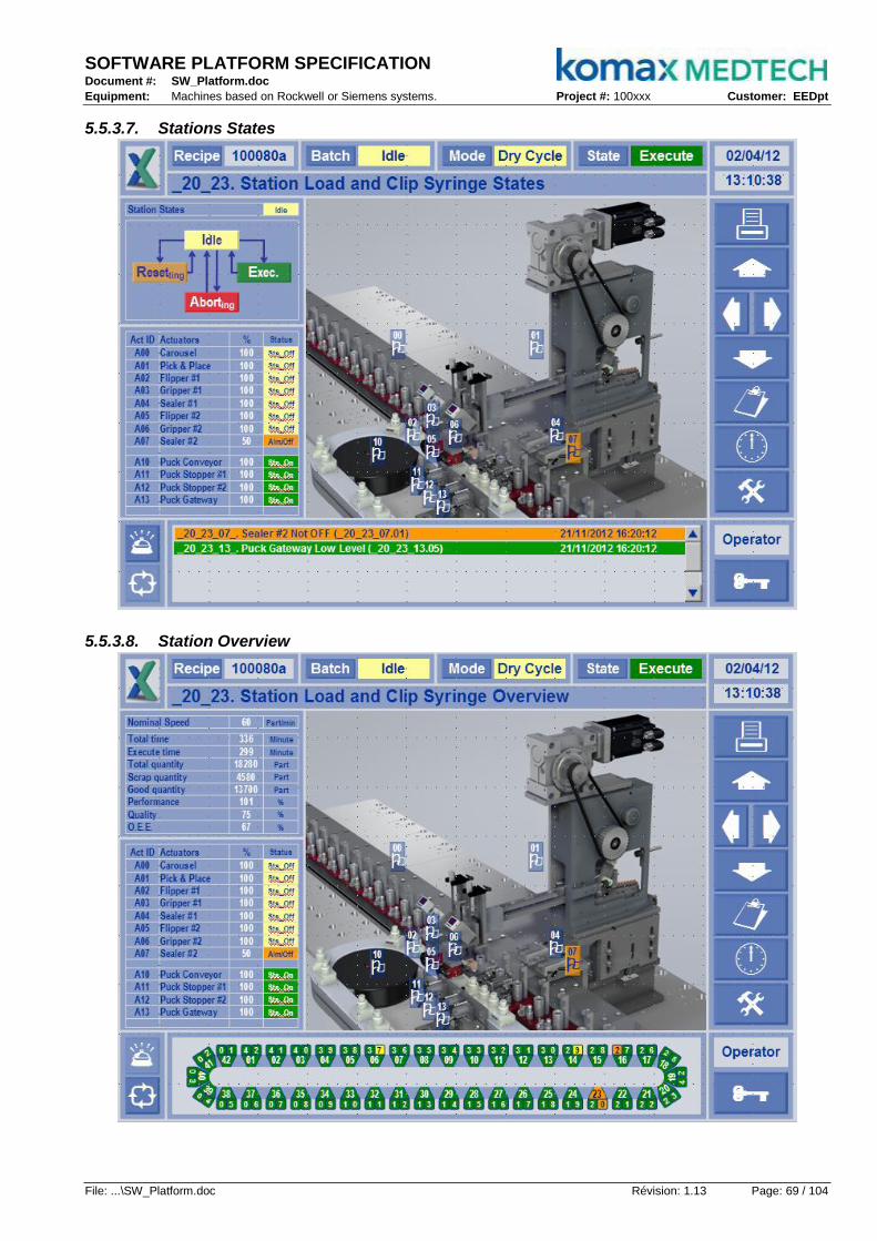
SOFTWARE PLATFORM SPECIFICATION Document #: SW_Platform.doc
Equipment: Machines based on Rockwell or Siemens systems. Project #: 100xxx Customer: EEDpt
File: ...\SW_Platform.doc Révision: 1.13 Page: 69 / 104
5.5.3.7. Stations States
5.5.3.8. Station Overview
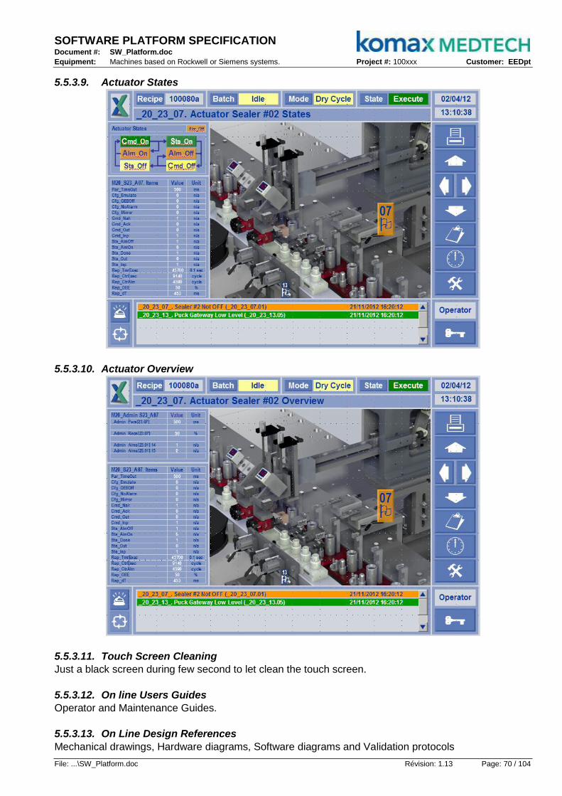
SOFTWARE PLATFORM SPECIFICATION Document #: SW_Platform.doc
Equipment: Machines based on Rockwell or Siemens systems. Project #: 100xxx Customer: EEDpt
File: ...\SW_Platform.doc Révision: 1.13 Page: 70 / 104
5.5.3.9. Actuator States
5.5.3.10. Actuator Overview
5.5.3.11. Touch Screen Cleaning
Just a black screen during few second to let clean the touch screen.
5.5.3.12. On line Users Guides
Operator and Maintenance Guides.
5.5.3.13. On Line Design References
Mechanical drawings, Hardware diagrams, Software diagrams and Validation protocols
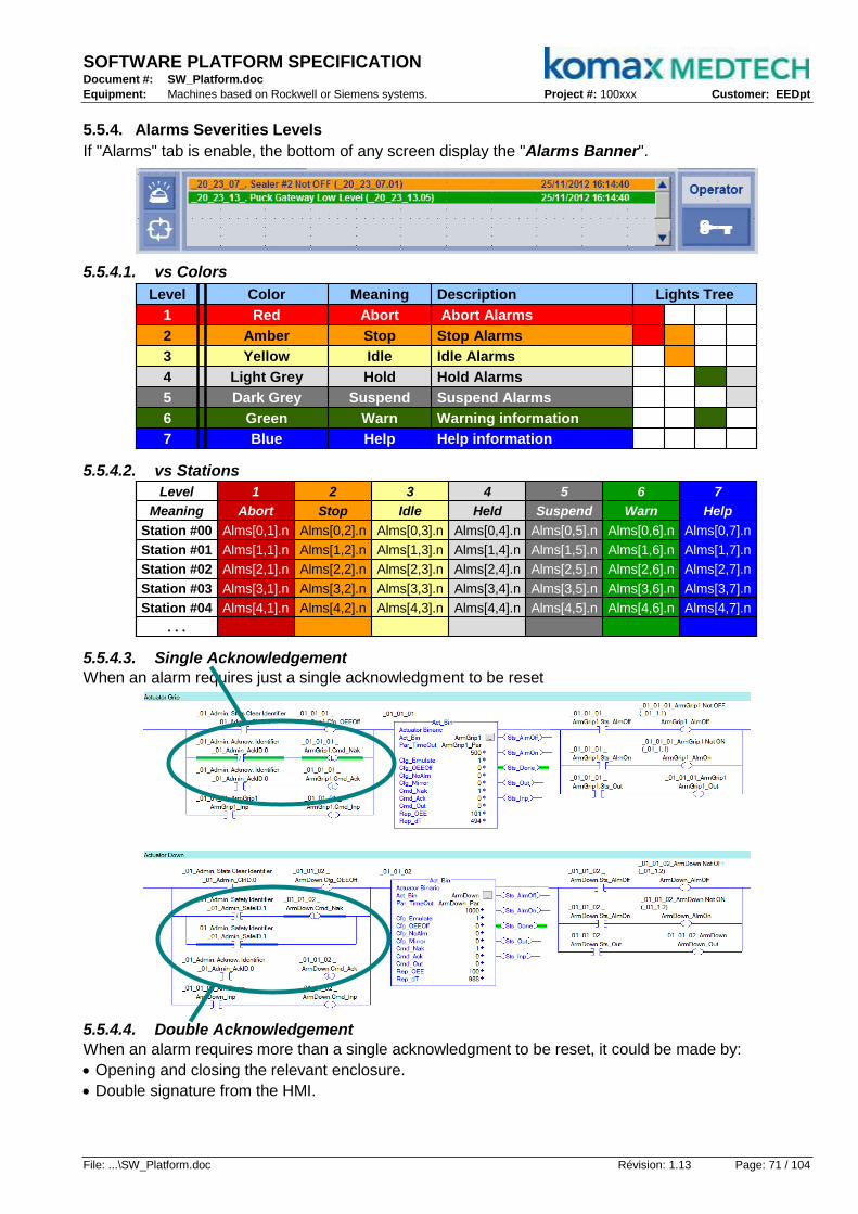
SOFTWARE PLATFORM SPECIFICATION Document #: SW_Platform.doc
Equipment: Machines based on Rockwell or Siemens systems. Project #: 100xxx Customer: EEDpt
File: ...\SW_Platform.doc Révision: 1.13 Page: 71 / 104
5.5.4. Alarms Severities Levels
If "Alarms" tab is enable, the bottom of any screen display the "Alarms Banner".
5.5.4.1. vs Colors
Lights Tree
Help information
Warning information
Suspend Alarms
Hold Alarms
Idle Alarms
Stop Alarms
Abort Alarms
Description
StopAmber2
IdleYellow3
HoldLight Grey4
SuspendDark Grey5
AbortRed1
WarnGreen6
HelpBlue7
MeaningLevel Color Lights Tree
Help information
Warning information
Suspend Alarms
Hold Alarms
Idle Alarms
Stop Alarms
Abort Alarms
Description
StopAmber2
IdleYellow3
HoldLight Grey4
SuspendDark Grey5
AbortRed1
WarnGreen6
HelpBlue7
MeaningLevel Color
5.5.4.2. vs Stations
Alms[4,7].nAlms[4,6].nAlms[4,5].nAlms[4,4].nAlms[4,3].nAlms[4,2].nAlms[4,1].nStation #04
Alms[3,7].nAlms[3,6].nAlms[3,5].nAlms[3,4].nAlms[3,3].nAlms[3,2].nAlms[3,1].nStation #03
Alms[2,7].nAlms[2,6].nAlms[2,5].nAlms[2,4].nAlms[2,3].nAlms[2,2].nAlms[2,1].nStation #02
Alms[1,7].nAlms[1,6].nAlms[1,5].nAlms[1,4].nAlms[1,3].nAlms[1,2].nAlms[1,1].nStation #01
Alms[0,6].n
Warn
6
HelpSuspendHeldIdleStopAbortMeaning
Alms[0,7].nAlms[0,5].nAlms[0,4].nAlms[0,3].nAlms[0,2].nAlms[0,1].nStation #00
. . .
Level 531 2 4 7
5.5.4.3. Single Acknowledgement
When an alarm requires just a single acknowledgment to be reset
5.5.4.4. Double Acknowledgement
When an alarm requires more than a single acknowledgment to be reset, it could be made by:
Opening and closing the relevant enclosure.
Double signature from the HMI.
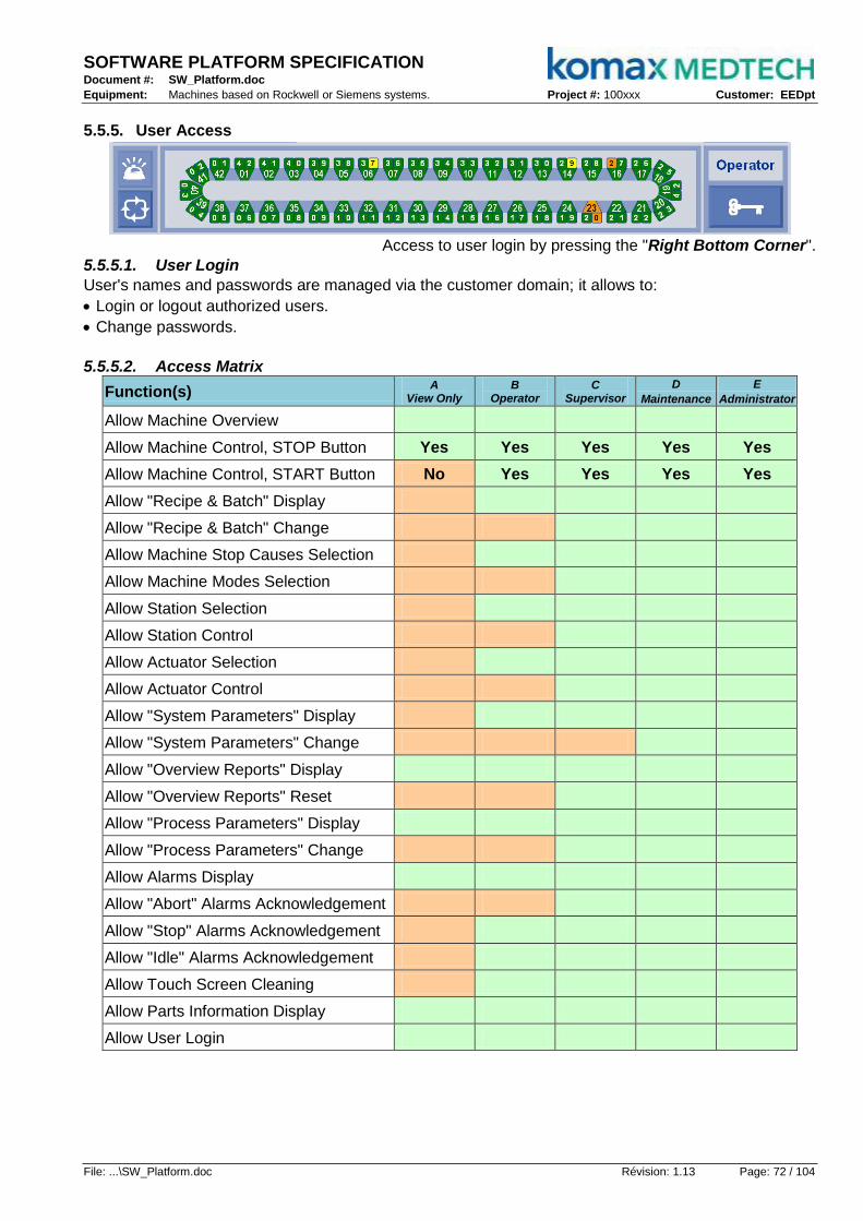
SOFTWARE PLATFORM SPECIFICATION Document #: SW_Platform.doc
Equipment: Machines based on Rockwell or Siemens systems. Project #: 100xxx Customer: EEDpt
File: ...\SW_Platform.doc Révision: 1.13 Page: 72 / 104
5.5.5. User Access
Access to user login by pressing the "Right Bottom Corner".
5.5.5.1. User Login
User's names and passwords are managed via the customer domain; it allows to:
Login or logout authorized users.
Change passwords.
5.5.5.2. Access Matrix
Function(s) A
View Only B
Operator C
Supervisor
D
Maintenance
E
Administrator
Allow Machine Overview
Allow Machine Control, STOP Button Yes Yes Yes Yes Yes
Allow Machine Control, START Button No Yes Yes Yes Yes
Allow "Recipe & Batch" Display
Allow "Recipe & Batch" Change
Allow Machine Stop Causes Selection
Allow Machine Modes Selection
Allow Station Selection
Allow Station Control
Allow Actuator Selection
Allow Actuator Control
Allow "System Parameters" Display
Allow "System Parameters" Change
Allow "Overview Reports" Display
Allow "Overview Reports" Reset
Allow "Process Parameters" Display
Allow "Process Parameters" Change
Allow Alarms Display
Allow "Abort" Alarms Acknowledgement
Allow "Stop" Alarms Acknowledgement
Allow "Idle" Alarms Acknowledgement
Allow Touch Screen Cleaning
Allow Parts Information Display
Allow User Login

SOFTWARE PLATFORM SPECIFICATION Document #: SW_Platform.doc
Equipment: Machines based on Rockwell or Siemens systems. Project #: 100xxx Customer: EEDpt
File: ...\SW_Platform.doc Révision: 1.13 Page: 73 / 104
6. Admin Details
6.1. Header
6.1.1. MainType
Could be "Machine" or "Sub-Machine".
6.1.2. Main_ID
"_Mn_Adm" if machine, should be from _00 to _99.
"_Mnn_Adm" if sub-machine, should be from _000 to _999.
6.1.3. SubType
All actuators required for machines or sub-machines administration are controlled in "Actuators_Sub".
EStopsOFF checks emergency stops.
DoorsClosed checks the enclosures safety feedbacks.
DoorsLock controls the enclosures interlocks.
Alm_Buzz manages the alarms and 2sec buzzer while starting.
Alm_White manages the white lamp in lights tree.
Alm_Green manages the green lamp in lights tree.
Alm_Amber manages the amber lamp in lights tree.
Alm_Red manages the red lamp in lights tree.
But_Stop manages the stop button with its lamp.
But_Start manages the start button with its lamp.
6.2. States & Modes
The normal access goes through reactions to operator panel (E-Stop, Stop and Start buttons); however, a remote access is available through Cmd_State. Another feature manages by admin logic is Sts_Mode versus Cmd_Mode only when Sts_State=Stopped; keep in mind that a mode change make state switch to Sts_State=Aborting.
6.2.1. E-Stop
"E-Stop" button or alarms initiate the "Aborting" acting state from any current state.
6.2.2. Stop
"Stop" button or alarms initiate the "Stopping" acting state from any current state if no abort pending.
"Stop" button initiates the "Aborting" acting state from "Stopped" state to unlock the doors.
6.2.3. Start
"Start" button initiates the "Resetting" acting state from "Stopped" state.
"Start" button initiates the "Starting" acting state from "Idle" state.
"Start" button acknowledges pending alarm versus current user login.
Suspend
Stopped ExecuteStarting
Reseting Susping
Mo
des
Ch
ang
e
Held HoldingAborting
Idle
Stoping
Aborted
Suspend
Stopped ExecuteStarting
Reseting Susping
Mo
des
Ch
ang
e
Held HoldingAborting
Idle
Stoping
Aborted

SOFTWARE PLATFORM SPECIFICATION Document #: SW_Platform.doc
Equipment: Machines based on Rockwell or Siemens systems. Project #: 100xxx Customer: EEDpt
File: ...\SW_Platform.doc Révision: 1.13 Page: 74 / 104
6.3. Public Data
The "_Adm" program merges every machine public "_Mn_Adm_..." data:
Name Tag Description
6.3.1. Current State Sts_State 1=Aborting, 2=Aborted, 3-Stopping, 4=Stopped, 5=Resetting, 6=Idle, 7=Starting, 8=Execute, 9=Holding, 10=Held, 11=Suspending, 12=Suspended.
6.3.2. Command State Cmd_State 1=Aborting, 2=Aborted, 3-Stopping, 4=Stopped, 5=Resetting, 6=Idle, 7=Starting, 8=Execute, 9=Holding, 10=Held, 11=Suspending, 12=Suspended.
6.3.3. Current Mode Sts_Mode 1=Producing, 2=Maintenance, 4=Manual, 8=Purge, 16=DryCycle, 32=SingleCycle, 64=LimpLeft, 128=LimpRight
6.3.4. Command Mode Cmd_Mode 1=Producing, 2=Maintenance, 4=Manual, 8=Purge, 16=DryCycle, 32=SingleCycle, 64=LimpLeft, 128=LimpRight
6.3.5. Login Identifier LogID Up to 32 user access groups.
6.3.6. Safety Identifier SafeID Up to 32 enclosures to discriminate.
6.3.7. Acknowledge Identifier AckID Update from LogID if Start button pressed and pending alarm.
6.3.8. Alarms Identifier AlmID Up to 7 different types of alarms.
6.3.8.1. Alarm to Abort Alm_Abort To request Aborting
6.3.8.2. Alarm to Stop Alm_Stop To request Stopping
6.3.8.3. Alarm to Idle Alm_Idle To request Resetting
6.3.8.4. Alarm to Suspend Alm_Susp To request Suspending
6.3.8.5. Alarm to Hold Alm_Hold To request Holding
6.3.8.6. Alarm to Warn Alm_Warn To warn operator
6.3.8.7. Alarm to Help Alm_Help To help operator
6.3.9. Clear Identifier ClrID To discriminate which statistics counters needs to be cleared.
6.3.9.1. Oper's Stats Clear Clr_Oper To clear Oper's statistics
6.3.9.2. Shift's Stats Clear Clr_Shift To clear Shift's statistics
6.3.9.3. Batch's Stats Clear Clr_Batch To clear Batch's statistics
6.3.10. Admin Array Adms To manage any statistics for real time OEE
6.3.10.1. Admin Operator Adm_Oper To manage Oper's statistics (real time OEE)
6.3.10.2. Admin Shift Adm_Shift To manage Shift's statistics (real time OEE)
6.3.10.3. Admin Batch Adm_Batch To manage Batch's statistics (real time OEE)
6.3.11. Alarms Array Alms Alarms array is in 2D, one for stations and the second for severities; so a 4 stations machine would be [05,10].
6.3.12. Camshafts Array Cams Camshafts array is in 2D, one for stations and the second for camshafts; so a 4 stations machine would be [05,10]
6.3.13. Parameters Array Pars Parameters array is in 2D, one for stations and the second for parameters; so a 4 stations machine would be [05,10]
6.3.14. Parameters Length ParsLen Parameters and Camshafts Length use by "Recipe Confirm"
6.3.15. Reports Array Reps Reports array is in 2D, one for stations and the second for reports; so a 4 stations machine would be [05,02]
6.3.16. Tracks Manager Tracks Tracks managers array is in 2D, one for stations and the second for sides; so a 4 stations with 2 tracks would be [05,02]
6.3.17. Nests Manager Nests Nests managers array is in 2D, one for stations and the second for sides; so a 4 stations with 2 tracks would be [05,02]
6.3.18. Nests Empty NestEmpty Indicates when every nest are empty

SOFTWARE PLATFORM SPECIFICATION Document #: SW_Platform.doc
Equipment: Machines based on Rockwell or Siemens systems. Project #: 100xxx Customer: EEDpt
File: ...\SW_Platform.doc Révision: 1.13 Page: 75 / 104
Name Tag Description
6.3.19. Nest Identifier NestID 1= Nest#1 in front of station #01, 2= Nest#2 in front of station #01
etc...
6.3.20. Part Identifier PartID 1= Part ID #00001, 2= Part ID #00002,
etc...
6.3.21. Pulse per Second PlsSec Second heart beat...
6.3.22. Batch Interface Batch MES to control multiple machines vs batch
6.3.23. Recipes Array Recips Storable and restorable parameters and camshafts collections
6.3.24. Recipe Name Recipe Name of active parameters and camshafts collection
6.3.25. Recipe ID RecipeID ID of active parameters and camshafts collection
...
6.4. Diagram
All sequences defined in the configuration admin form are coded in the "Program_Logic". MainType Station SubType Act_Bin Act_Bin Act_Bin Act_Bin Act_Bin Act_Bin Act_Bin Act_Bin Revision V001_110810
Main_ID _01_Adm Sub_ID _00 _01 _02 _03 _04 _05 _06 _07 Abort n/a
MainName _ SubName SafeGuard Alm_Buzz Alm_White Alm_Green Alm_Amber Alm_Red But_Stop But_Start Reset n/a
MaindT#### 2000 SubdT#### 1000 1000 1000 1000 1000 1000 30 30 Exec n/a
Cmd_Out:=0 Cmd_Out:=0 Cmd_Out:=0 Flashing Flashing Flash if Alm Mach_Abort:=1 State:=01
Sts_Inp=0 AlmAbort=1 Sts_Inp=1 Mach_Idle=0
Cmd_Out:=0 Cmd_Out:=0 Cmd_Out:=0 Cmd_Out:=0 Steady Flashing Flash if Alm Sts_Safe:=00 State:=02
Sts_Inp=0 AlmAbort=1 Sts_Inp=0 Mach_Idle=1
Cmd_Out:=1 Cmd_Out:=0 Cmd_Out:=0 Flashing Cmd_Out:=0 Flashing Flash if Alm State:=03
Sts_Inp=1 AlmStop=1 Sts_Inp=1
Cmd_Out:=0 Cmd_Out:=0 Steady Cmd_Out:=0 Steady Flash if Alm Sts_Safe:=FF State:=04
Sts_Inp=1 AlmStop=1 Sts_Inp=0 Sts_Inp=0
State=04 Sts_Inp=0 Sts_Inp=1 Mach_Reset:=1 State:=05
Cmd_Out:=0 Flashing Flashing Cmd_Out:=0 Flashing Steady State:=06
AlmIdle=0 Mach_Idle=1
Cfg_NoAlm:=0 Cmd_Out:=0 Flashing Steady Cmd_Out:=0 Steady Flashing State:=07
Sts_Inp=1
Cmd_Out:=1 Cmd_Out:=0 Flashing Cmd_Out:=0 Cmd_Out:=0 Flashing Steady State:=06
Cfg_NoAlm=0 Sts_Inp=0
Sts_Inp=1 Sts_Inp=1 State:=08
Cfg_NoAlm:=1 Cmd_Out:=0 Steady Cmd_Out:=0 Cmd_Out:=0 Flashing Flash if Alm Mach_Exec:=1 State:=05
AlmIdle=1
AlmHold=1 State:=09
AlmSusp=1 State:=11
Flashing Steady Cmd_Out:=0 Cmd_Out:=0 Flashing Flash if Alm State:=10
Mach_Idle=1
Steady Flashing Cmd_Out:=0 Cmd_Out:=0 Flashing Flash if Alm State:=07
AlmHold=0
Flashing Cmd_Out:=0 Steady Cmd_Out:=0 Flashing Flash if Alm State:=12
Mach_Idle=1
Staedy Cmd_Out:=0 Flashing Cmd_Out:=0 Flashing Flash if Alm State:=07
AlmSusp=0Suspended, 12 State=12
Suspending, 11
State=09
State=11
State=07
Held, 10
State=08
Holding, 09
State=10
Aborting, 01State
Any
Stopping, 03
Execute, 08
Starting, 07
State=06
Aborted, 02
Stopped, 04
State=05
State
Any
Resetting, 05
Idle, 06
State
Any
State
Any
The admin program is a mix between procedural and imperative logic; the Sts_State is the key; the related actuators reacts on the Sts_State values.

SOFTWARE PLATFORM SPECIFICATION Document #: SW_Platform.doc
Equipment: Machines based on Rockwell or Siemens systems. Project #: 100xxx Customer: EEDpt
File: ...\SW_Platform.doc Révision: 1.13 Page: 76 / 104
6.5. Interfaces Configuration
The configuration of the data seen in "Admin" are based on a matrix approach where rows could be related to stations and columns to station's components.
6.5.1. Admin Statistics
Admin Statistics Operator Shift Batch . . .
Machine #01 Adms[0] Adms[1] Adms[2] . . .
. . .
6.5.2. Alarms vs Stations & Severities
Level 1 2 3 4 5 6 7
Meaning Abort Stop Idle Held Suspend Warn Help
Station #00 _Alms[0,1].n _Alms[0,2].n _Alms[0,3].n _Alms[0,4].n _Alms[0,5].n _Alms[0,6].n _Alms[0,7].n
Station #01 _Alms[1,1].n _Alms[1,2].n _Alms[1,3].n _Alms[1,4].n _Alms[1,5].n _Alms[1,6].n _Alms[1,7].n
. . .
6.5.3. Parameters / Cams vs Stations
Parameters Param. 0 Param. 1 Param. 2 . . .
Station #00 Pars[0,0] / Cams[0,0] Pars[0,1] / Cams[0,1] Pars[0,2] / Cams[0,2] . . .
Station #01 Pars[1,0] / Cams[1,0] Pars[1,1] / Cams[1,1] Pars[1,2] / Cams[1,2] . . .
Station #02 Pars[2,0] / Cams[2,0] Pars[2,1] / Cams[2,1] Pars[2,2] / Cams[2,2] . . .
Station #03 Pars[3,0] / Cams[3,0] Pars[3,1] / Cams[3,1] Pars[3,2] / Cams[3,2] . . .
Station #04 Pars[4,0] / Cams[4,0] Pars[4,1] / Cams[4,1] Pars[4,2] / Cams[4,2] . . .
. . .
6.5.4. Reports vs Stations
Reports Report 0 Report 1 Report 2 . . .
Station #00 Reps[0,0] Reps[0,1] Reps[0,2] . . .
Station #01 Reps[1,0] Reps[1,1] Reps[1,2] . . .
Station #02 Reps[2,0] Reps[2,1] Reps[2,2] . . .
Station #03 Reps[3,0] Reps[3,1] Reps[3,2] . . .
Station #04 Reps[4,0] Reps[4,1] Reps[4,2] . . .
. . .
6.5.5. Tracks vs Station's Sides
Statistics First Side Second Side . . .
Station #00 Tracks[0,0] N/A . . .
Station #01 Tracks[1,0] Tracks[1,1] . . .
Station #02 Tracks[2,0] Tracks[2,1] . . .
Station #03 Tracks[3,0] Tracks[3,1] . . .
Station #04 Tracks[4,0] Tracks[4,1] . . .
. . .
6.5.6. Nests Managers vs Fixture's Sides
Nests Manager First Side Second Side . . .
Station #00 N/A N/A . . .
Station #01 Nests[1,0] Nests[1,1] . . .
Station #02 Nests[2,0] Nests[2,1] . . .
Station #03 Nests[3,0] Nests[3,1] . . .
Station #04 Nests[4,0] Nests[4,1] . . .
. . .

SOFTWARE PLATFORM SPECIFICATION Document #: SW_Platform.doc
Equipment: Machines based on Rockwell or Siemens systems. Project #: 100xxx Customer: EEDpt
File: ...\SW_Platform.doc Révision: 1.13 Page: 77 / 104
6.6. PLC Files
6.6.1. Programs Tags
This folder contains every tags defined as private and every tags defined as alias to public references.
6.6.2. Program_Logic
This program contains the logic to manage Sts_State and Sts_Mode versus operator panel (or remote).
6.6.3. Actuators_Sub
This subroutine merges every instruction in charge of actuators related to the machine administration.
6.6.4. AlmScan_Sub
This subroutine scans _Mn_Adm_Alms array to find out the kind of alarm that could be pending
6.7. HMI Screen
See §7.5.3 ...

SOFTWARE PLATFORM SPECIFICATION Document #: SW_Platform.doc
Equipment: Machines based on Rockwell or Siemens systems. Project #: 100xxx Customer: EEDpt
File: ...\SW_Platform.doc Révision: 1.13 Page: 78 / 104
7. Machine Details
7.1. Header
The header configures the machine organization.
MainType Machine SubType Station Station Station Station Station Station
Main_ID _01 Sub_ID _00 _01 _02 _03 _04 _Admin
MainName Machine SubName BaseFibro LoadBody LoadScrew BuildPart UnloadPart _
MaindT#### 9500 SubdT#### 800 6500 6500 8500 6500 2000
7.1.1. MainType
Could be "Machine" or "Sub-Machine".
7.1.2. Main_ID
"_Mn" if machine, should be from _00 to _99.
"_Mnn" if sub-machine, should be from _000 to _999.
7.1.3. MainName
The convenient machine or sub-machine name description.
7.1.4. MaindT
The ideal expected time response in msec.
7.1.5. SubType
Could be sub_machine or station; the stations are declared in the machine form; one station is equivalent to one column. Usually machine or sub-machine do not need actuator; if not, the routine "Actuators_Sub" would be added.
7.1.6. Sub_ID
If station, should be "M" (_<Sub_MachID>) identifier from 0 to 9.
If station, should be "_Ss" (_<StationID>) identifier from _00 to _99.
7.1.7. SubName
The convenient sub-machine or station name description.
7.1.8. SubdT####
The ideal expected time response in msec.
7.1.9. _Adm
If it's not a sub-machine, the latest "station" is dedicated for the "_Adm" program declaration that is always attached to any machines; for this one, no "_ID" number, just "_Adm" statement.
7.2. States
▼ ▲▼ ▲▼ ▲▼ ▲
Stations
▼ ▲▼ ▲ Reseting
Exec.
Aborting Idle
Reseting
Exec.
Aborting Idle
7.2.1. Abort
When Prog.Cmd_State = 1 and Admin_State = 1 (Aborting) then set sequence #01.
7.2.2. Reset
When Prog.Cmd_State = 2 and Admin_State = 5 (Resetting) then set sequence #11.
7.2.3. Exec
When Prog.Cmd_State = 4 send And Admin_State = 8 (Execute) then set sequence #21.
Revision V001_110810
Abort Sts_Seq:=01
Reset Sts_Seq:=11
Exec Sts_Seq:=21

SOFTWARE PLATFORM SPECIFICATION Document #: SW_Platform.doc
Equipment: Machines based on Rockwell or Siemens systems. Project #: 100xxx Customer: EEDpt
File: ...\SW_Platform.doc Révision: 1.13 Page: 79 / 104
7.3. Diagram
MainType Machine SubType Station Station Station Station Station Station Revision V001_110810
Main_ID _01 Sub_ID _00 _01 _02 _03 _04 _Admin Abort Sts_Seq:=01
MainName Machine SubName BaseFibro LoadBody LoadScrew BuildPart UnloadPart _ Reset Sts_Seq:=11
MaindT#### 7300 SubdT#### 800 6000 6500 6500 6500 2000 Exec Sts_Seq:=21
Cmd_State:=1 Cmd_State:=1 Cmd_State:=1 Cmd_State:=1 Aborting=1 Sts_Safe:=0
Sts_Idle=1 Sts_Idle=1 Sts_Idle=1 Sts_Idle=1
Cmd_State:=1 Sts_Safe:=1
Sts_Idle=1 Aborted:=1 Sts_Idle:=1
Resetting=1
Cmd_State:=2 Cmd_State:=2 Cmd_State:=2 Cmd_State:=2 Sts_Safe:=0
Sts_Idle=1 Sts_Idle=1 Sts_Idle=1 Sts_Idle=1
Cmd_State:=2 Sts_Safe:=1
Sts_Idle=1 Idle:=1 Sts_Idle:=1
Cmd_State:=4 Cmd_State:=4 Cmd_State:=4 Cmd_State:=4 Execute=1 Sts_Safe:=0
Sts_Idle=1 Sts_Idle=1 Sts_Idle=1 Sts_Idle=1
Cmd_State:=4 Sts_Safe:=1
Sts_Idle=1 Sts_Idle:=1
Abort every process station Sts_Seq=01 Cmd_Seq:=02
Abort BaseFibro Sts_Seq=02
Reset Base Fibro Sts_Seq=13
Exec every process Station Sts_Seq=21 Cmd_Seq:=22
Exec Base Fibro Sts_Seq=22
Mode=1-Producing, Mode=2-Maintenance, Mode=4-Manual
Mode=8-Purge, Mode=16-DryCycleSts_Seq=11 Cmd_Seq:=12
Reset every process Station Sts_Seq=12 Cmd_Seq:=13
Config Tracks vs Mode
All sequences defined in the configuration machine form are coded in the "Program_Logic".
The sequence #01 to #02 control "Abort" stations requests.
o Abort station #01 to #04 and check their completion.
o Abort station #00 (the transport) and go to idle.
The sequence #11 to #14 control "Reset" stations requests.
o Configure StationID versus current mode.
o Reset station #01 to #04 versus StationID and check their completion.
o Reset station #00 versus StationID (the transport) and go to idle.
The sequence #21 to #24 controls "Exec" stations requests.
o Exec station #01 to #04 versus StationID and check their completion.
o Exec station #00 versus StationID (the transport) and go to idle.
7.4. Public Data
Name Tag Description
7.4.1. Program Manager Prog The instance of class Mgr_Prog to manage states and sequences.
7.4.2. Program Track Track The instance of class Mgr_Track to manage statistics and consecutives errors.
7.4.3. Motions Group Motions Motions Group (depends on the PLC's technology).
7.4.4. Motions Array Mots Motions Real array [#,0] = Servo Number, Output Value (Setpoints) [#,1] = Servo Number, Input Value (Position)
7.4.5. Outputs Array Outs Outputs Boolean array
7.4.6. Inputs Array Inps Inputs Boolean array
...
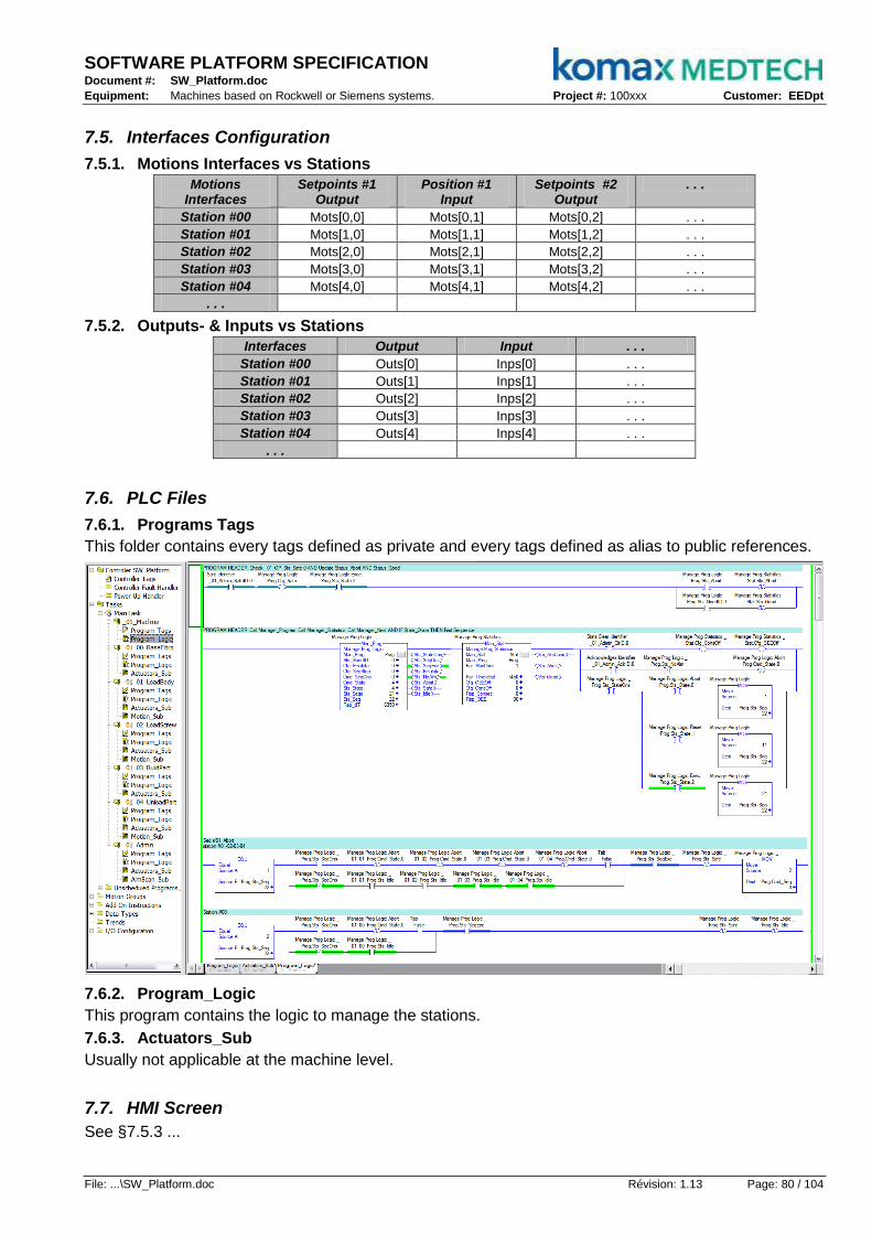
SOFTWARE PLATFORM SPECIFICATION Document #: SW_Platform.doc
Equipment: Machines based on Rockwell or Siemens systems. Project #: 100xxx Customer: EEDpt
File: ...\SW_Platform.doc Révision: 1.13 Page: 80 / 104
7.5. Interfaces Configuration
7.5.1. Motions Interfaces vs Stations
Motions Interfaces
Setpoints #1 Output
Position #1 Input
Setpoints #2 Output
. . .
Station #00 Mots[0,0] Mots[0,1] Mots[0,2] . . .
Station #01 Mots[1,0] Mots[1,1] Mots[1,2] . . .
Station #02 Mots[2,0] Mots[2,1] Mots[2,2] . . .
Station #03 Mots[3,0] Mots[3,1] Mots[3,2] . . .
Station #04 Mots[4,0] Mots[4,1] Mots[4,2] . . .
. . .
7.5.2. Outputs- & Inputs vs Stations
Interfaces Output Input . . .
Station #00 Outs[0] Inps[0] . . .
Station #01 Outs[1] Inps[1] . . .
Station #02 Outs[2] Inps[2] . . .
Station #03 Outs[3] Inps[3] . . .
Station #04 Outs[4] Inps[4] . . .
. . .
7.6. PLC Files
7.6.1. Programs Tags
This folder contains every tags defined as private and every tags defined as alias to public references.
7.6.2. Program_Logic
This program contains the logic to manage the stations.
7.6.3. Actuators_Sub
Usually not applicable at the machine level.
7.7. HMI Screen
See §7.5.3 ...
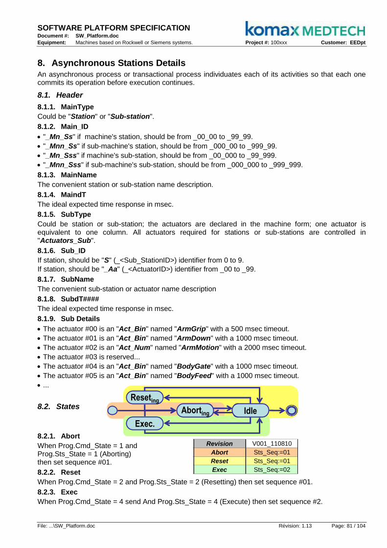
SOFTWARE PLATFORM SPECIFICATION Document #: SW_Platform.doc
Equipment: Machines based on Rockwell or Siemens systems. Project #: 100xxx Customer: EEDpt
File: ...\SW_Platform.doc Révision: 1.13 Page: 81 / 104
8. Asynchronous Stations Details An asynchronous process or transactional process individuates each of its activities so that each one commits its operation before execution continues.
8.1. Header
8.1.1. MainType
Could be "Station" or "Sub-station".
8.1.2. Main_ID
"_Mn_Ss" if machine's station, should be from _00_00 to _99_99.
"_Mnn_Ss" if sub-machine's station, should be from _000_00 to _999_99.
"_Mn_Sss" if machine's sub-station, should be from _00_000 to _99_999.
"_Mnn_Sss" if sub-machine's sub-station, should be from _000_000 to _999_999.
8.1.3. MainName
The convenient station or sub-station name description.
8.1.4. MaindT
The ideal expected time response in msec.
8.1.5. SubType
Could be station or sub-station; the actuators are declared in the machine form; one actuator is equivalent to one column. All actuators required for stations or sub-stations are controlled in "Actuators_Sub".
8.1.6. Sub_ID
If station, should be "S" (_<Sub_StationID>) identifier from 0 to 9.
If station, should be "_Aa" (_<ActuatorID>) identifier from _00 to _99.
8.1.7. SubName
The convenient sub-station or actuator name description
8.1.8. SubdT####
The ideal expected time response in msec.
8.1.9. Sub Details
The actuator #00 is an "Act_Bin" named "ArmGrip" with a 500 msec timeout.
The actuator #01 is an "Act_Bin" named "ArmDown" with a 1000 msec timeout.
The actuator #02 is an "Act_Num" named "ArmMotion" with a 2000 msec timeout.
The actuator #03 is reserved...
The actuator #04 is an "Act_Bin" named "BodyGate" with a 1000 msec timeout.
The actuator #05 is an "Act_Bin" named "BodyFeed" with a 1000 msec timeout.
...
8.2. States
8.2.1. Abort
When Prog.Cmd_State = 1 and Prog.Sts_State = 1 (Aborting) then set sequence #01.
8.2.2. Reset
When Prog.Cmd_State = 2 and Prog.Sts_State = 2 (Resetting) then set sequence #01.
8.2.3. Exec
When Prog.Cmd_State = 4 send And Prog.Sts_State = 4 (Execute) then set sequence #2.
▼ ▲▼ ▲▼ ▲▼ ▲
Stations
▼ ▲▼ ▲ Reseting
Exec.
Aborting Idle
Reseting
Exec.
Aborting Idle
MainType Station SubType Act_Bin Act_Bin Act_Bin Act_Num Act_Bin Act_Bin Revision V001_110810
Main_ID _01_01 Sub_ID _00 _01 _02 _03 _04 _05 Abort Sts_Seq:=01
MainName LoadBody SubName ArmGrip0 ArmGrip1 ArmDown ArmMotion BodyGate BodyFeed Reset Sts_Seq:=01
MaindT#### 6000 SubdT#### 500 500 1000 2000 1000 1000 Exec Sts_Seq:=02
Cmd_Out:=0 Cmd_Out:=0 Sts_Safe:=0
Sts_Inp=0 Sts_Inp=0
Cmd_Out:=1 Cmd_Out:=1
Sts_Inp=1 Sts_Inp=1
Cmd_Out:=1 Cmd_Out:=0
Sts_Inp=1 Sts_Inp=0
Cmd_Out:=1 Cmd_Out:=1
Sts_Inp=1 Sts_Inp=1
Cmd_Out:=0
Sts_Inp=0
Cmd_Sp:=06 Sts_Safe:=0
Sts_Inp=0
Cmd_Out:=1
Sts_Inp=1
Cmd_Out:=0 Cmd_Out:=0
Sts_Inp=0 Sts_Inp=0
Cmd_Out:=0
Sts_Inp=0
Cmd_Sp:=10 Sts_Safe:=1
Sts_Inp=1 Sts_Idle:=1
Name Domain DataType TagType
Prog Public Man_Prog Alias
Track0 Public Man_Track Alias
Track1 Public Man_Track Alias
Nest0 Public Man_Nest Alias
Nest1 Public Man_Nest Alias
ArmAxe Public AXIS_GENERIC Tag
ArmCtl Private MOTION_INSTRUCTION[10] Tag
ArmSts Private DINT Tag
Manage Nest0 Statistics _01_Admin_Nests[1,0]
Manage Track1 Statistics _01_Admin_Tracks[1,1]
Sts_Seq=02
Disable Feeder + Close Gate Sts_Seq=01 Cmd_Seq:=08
Armp Up on pick Sts_Seq=05 Cmd_Seq:=06
Arm Down on pick
Close GateSts_Seq=03 Cmd_Seq:=04
Close Gripper on pick
Arm Down on place Sts_Seq=07 Cmd_Seq:=08
Cmd_Seq:=03
Sts_Seq=04 Cmd_Seq:=05
Arm Up to place Sts_Seq=06 Cmd_Seq:=07
Enable Feeder + Open Gate
Open Gripper Sts_Seq=08 Cmd_Seq:=09
Arm Up Sts_Seq=09 Cmd_Seq:=10
Arm Up to pick Sts_Seq=10
Description TagReference
Motion Axis _01_01_ArmAxe
Manage Nest1 Statistics _01_Admin_Nests[1,1]
Manage Prog Logic
Manage Track0 Statistics _01_Admin_Tracks[1,0]
Motion Control
Motion Status

SOFTWARE PLATFORM SPECIFICATION Document #: SW_Platform.doc
Equipment: Machines based on Rockwell or Siemens systems. Project #: 100xxx Customer: EEDpt
File: ...\SW_Platform.doc Révision: 1.13 Page: 82 / 104
8.3. Diagram
All sequences defined in the configuration station form are coded in the "Program_Logic".
The sequence #01 controls actuators #04 and #05 to reset "Sts_Safe" and command sequence #08.
The sequence #02 controls actuators #04 and #05 to command sequence #03.
...
The sequence #10 controls actuators #02 to set "Sts_Safe" and "Sts_Idle" to complete sequencer.
MainType Station SubType Act_Bin Act_Bin Act_Bin Act_Num Act_Bin Act_Bin Revision V001_110810
Main_ID _01_01 Sub_ID _00 _01 _02 _03 _04 _05 Abort Sts_Seq:=01
MainName LoadBody SubName ArmGrip0 ArmGrip1 ArmDown ArmMotion BodyGate BodyFeed Reset Sts_Seq:=01
MaindT#### 6000 SubdT#### 500 500 1000 2000 1000 1000 Exec Sts_Seq:=02
Cmd_Out:=0 Cmd_Out:=0 Sts_Safe:=0
Sts_Inp=0 Sts_Inp=0
Cmd_Out:=1 Cmd_Out:=1
Sts_Inp=1 Sts_Inp=1
Cmd_Out:=1 Cmd_Out:=0
Sts_Inp=1 Sts_Inp=0
Cmd_Out:=1 Cmd_Out:=1
Sts_Inp=1 Sts_Inp=1
Cmd_Out:=0
Sts_Inp=0
Cmd_Sp:=06 Sts_Safe:=0
Sts_Inp=0
Cmd_Out:=1
Sts_Inp=1
Cmd_Out:=0 Cmd_Out:=0
Sts_Inp=0 Sts_Inp=0
Cmd_Out:=0
Sts_Inp=0
Cmd_Sp:=10 Sts_Safe:=1
Sts_Inp=1 Sts_Idle:=1
Name Domain DataType TagType
Prog Public Man_Prog Alias
Track0 Public Man_Track Alias
Track1 Public Man_Track Alias
Nest0 Public Man_Nest Alias
Nest1 Public Man_Nest Alias
ArmAxe Public AXIS_GENERIC Tag
ArmCtl Private MOTION_INSTRUCTION[10] Tag
ArmSts Private DINT Tag
Manage Nest0 Statistics _01_Admin_Nests[1,0]
Manage Track1 Statistics _01_Admin_Tracks[1,1]
Sts_Seq=02
Disable Feeder + Close Gate Sts_Seq=01 Cmd_Seq:=08
Armp Up on pick Sts_Seq=05 Cmd_Seq:=06
Arm Down on pick
Close GateSts_Seq=03 Cmd_Seq:=04
Close Gripper on pick
Arm Down on place Sts_Seq=07 Cmd_Seq:=08
Cmd_Seq:=03
Sts_Seq=04 Cmd_Seq:=05
Arm Up to place Sts_Seq=06 Cmd_Seq:=07
Enable Feeder + Open Gate
Open Gripper Sts_Seq=08 Cmd_Seq:=09
Arm Up Sts_Seq=09 Cmd_Seq:=10
Arm Up to pick Sts_Seq=10
Description TagReference
Motion Axis _01_01_ArmAxe
Manage Nest1 Statistics _01_Admin_Nests[1,1]
Manage Prog Logic
Manage Track0 Statistics _01_Admin_Tracks[1,0]
Motion Control
Motion Status
8.4. Public Data
8.4.1. Prog
The instance of class Mgr_Prog to manage states and sequences.
8.4.2. Track0
The instance of class Mgr_Track to manage statistics and consecutives errors of 1st side [station,up].
8.4.3. Track1
The instance of class Mgr_Track to manage statistics and consecutives errors of 2nd side [station,up].
8.4.4. Nest0
The instance of class Mgr_Nest to manage statistics of pointed nest on 1st side [station,up].
8.4.5. Nest1
The instance of class Mgr_Nest to manage statistics of pointed nest on 1st side [station,up].
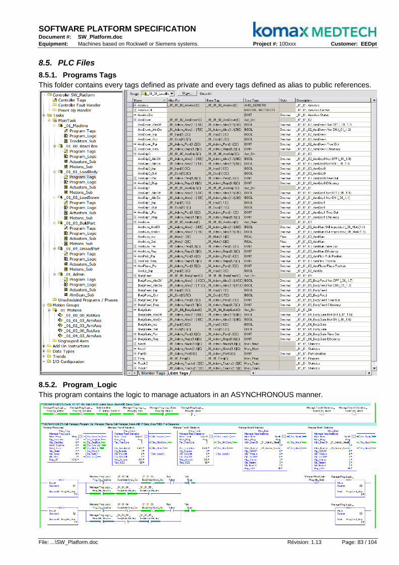
SOFTWARE PLATFORM SPECIFICATION Document #: SW_Platform.doc
Equipment: Machines based on Rockwell or Siemens systems. Project #: 100xxx Customer: EEDpt
File: ...\SW_Platform.doc Révision: 1.13 Page: 83 / 104
8.5. PLC Files
8.5.1. Programs Tags
This folder contains every tags defined as private and every tags defined as alias to public references.
8.5.2. Program_Logic
This program contains the logic to manage actuators in an ASYNCHRONOUS manner.

SOFTWARE PLATFORM SPECIFICATION Document #: SW_Platform.doc
Equipment: Machines based on Rockwell or Siemens systems. Project #: 100xxx Customer: EEDpt
File: ...\SW_Platform.doc Révision: 1.13 Page: 84 / 104
8.5.3. Actuators_Sub
This subroutine merges every instruction in charge of actuators related to the station.
8.5.4. Motion_Sub
In case of motion (servo-motor) presence, this subroutine contains the instructions to manage it.
8.6. HMI Screen
See §7.5.3 ...
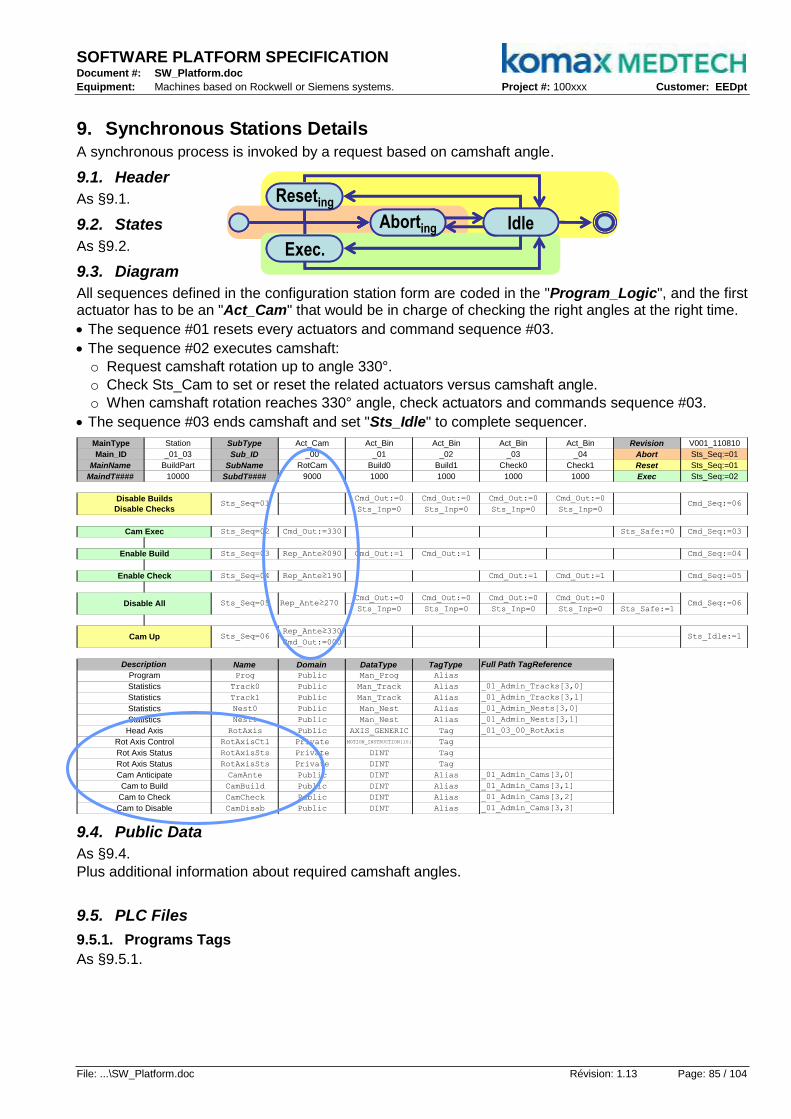
SOFTWARE PLATFORM SPECIFICATION Document #: SW_Platform.doc
Equipment: Machines based on Rockwell or Siemens systems. Project #: 100xxx Customer: EEDpt
File: ...\SW_Platform.doc Révision: 1.13 Page: 85 / 104
9. Synchronous Stations Details A synchronous process is invoked by a request based on camshaft angle.
9.1. Header
As §9.1.
9.2. States
As §9.2.
9.3. Diagram
All sequences defined in the configuration station form are coded in the "Program_Logic", and the first actuator has to be an "Act_Cam" that would be in charge of checking the right angles at the right time.
The sequence #01 resets every actuators and command sequence #03.
The sequence #02 executes camshaft:
o Request camshaft rotation up to angle 330°.
o Check Sts_Cam to set or reset the related actuators versus camshaft angle.
o When camshaft rotation reaches 330° angle, check actuators and commands sequence #03.
The sequence #03 ends camshaft and set "Sts_Idle" to complete sequencer.
MainType Station SubType Act_Cam Act_Bin Act_Bin Act_Bin Act_Bin Revision V001_110810
Main_ID _01_03 Sub_ID _00 _01 _02 _03 _04 Abort Sts_Seq:=01
MainName BuildPart SubName RotCam Build0 Build1 Check0 Check1 Reset Sts_Seq:=01
MaindT#### 10000 SubdT#### 9000 1000 1000 1000 1000 Exec Sts_Seq:=02
Cmd_Out:=0 Cmd_Out:=0 Cmd_Out:=0 Cmd_Out:=0
Sts_Inp=0 Sts_Inp=0 Sts_Inp=0 Sts_Inp=0
Sts_Seq=02 Cmd_Out:=330 Sts_Safe:=0 Cmd_Seq:=03
Sts_Seq=03 Rep_Ante≥090 Cmd_Out:=1 Cmd_Out:=1 Cmd_Seq:=04
Sts_Seq=04 Rep_Ante≥190 Cmd_Out:=1 Cmd_Out:=1 Cmd_Seq:=05
Cmd_Out:=0 Cmd_Out:=0 Cmd_Out:=0 Cmd_Out:=0
Sts_Inp=0 Sts_Inp=0 Sts_Inp=0 Sts_Inp=0 Sts_Safe:=1
Rep_Ante≥330
Cmd_Out:=000
Name Domain DataType TagType
Prog Public Man_Prog Alias
Track0 Public Man_Track Alias
Track1 Public Man_Track Alias
Nest0 Public Man_Nest Alias
Nest1 Public Man_Nest Alias
RotAxis Public AXIS_GENERIC Tag
RotAxisCtl Private MOTION_INSTRUCTION[10] Tag
RotAxisSts Private DINT Tag
RotAxisSts Private DINT Tag
CamAnte Public DINT Alias
CamBuild Public DINT Alias
CamCheck Public DINT Alias
CamDisab Public DINT Alias
Rot Axis Status
Rot Axis Control
Rot Axis Status
Cmd_Seq:=06
Sts_Idle:=1
Disable All Sts_Seq=05 Rep_Ante≥270
Cam Exec
Enable Build
Enable Check
Cmd_Seq:=06
Cam Up
Head Axis _01_03_00_RotAxis
Disable Builds
Disable ChecksSts_Seq=01
Statistics
Description
Program
_01_Admin_Tracks[3,0]
_01_Admin_Tracks[3,1]
_01_Admin_Nests[3,0]
Cam to Disable _01_Admin_Cams[3,3]
Cam to Build
_01_Admin_Cams[3,0]Cam Anticipate
_01_Admin_Cams[3,1]
Cam to Check _01_Admin_Cams[3,2]
Sts_Seq=06
Statistics
Statistics
Full Path TagReference
_01_Admin_Nests[3,1]
Statistics
9.4. Public Data
As §9.4.
Plus additional information about required camshaft angles.
9.5. PLC Files
9.5.1. Programs Tags
As §9.5.1.
▼ ▲▼ ▲▼ ▲▼ ▲
Stations
▼ ▲▼ ▲ Reseting
Exec.
Aborting Idle
Reseting
Exec.
Aborting Idle
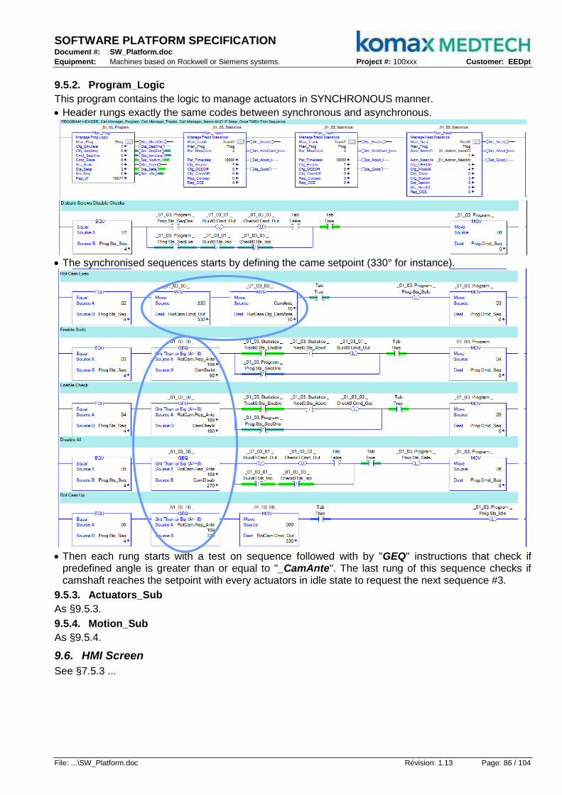
SOFTWARE PLATFORM SPECIFICATION Document #: SW_Platform.doc
Equipment: Machines based on Rockwell or Siemens systems. Project #: 100xxx Customer: EEDpt
File: ...\SW_Platform.doc Révision: 1.13 Page: 86 / 104
9.5.2. Program_Logic
This program contains the logic to manage actuators in SYNCHRONOUS manner.
Header rungs exactly the same codes between synchronous and asynchronous.
The synchronised sequences starts by defining the came setpoint (330° for instance).
Then each rung starts with a test on sequence followed with by "GEQ" instructions that check if
predefined angle is greater than or equal to "_CamAnte". The last rung of this sequence checks if camshaft reaches the setpoint with every actuators in idle state to request the next sequence #3.
9.5.3. Actuators_Sub
As §9.5.3.
9.5.4. Motion_Sub
As §9.5.4.
9.6. HMI Screen
See §7.5.3 ...
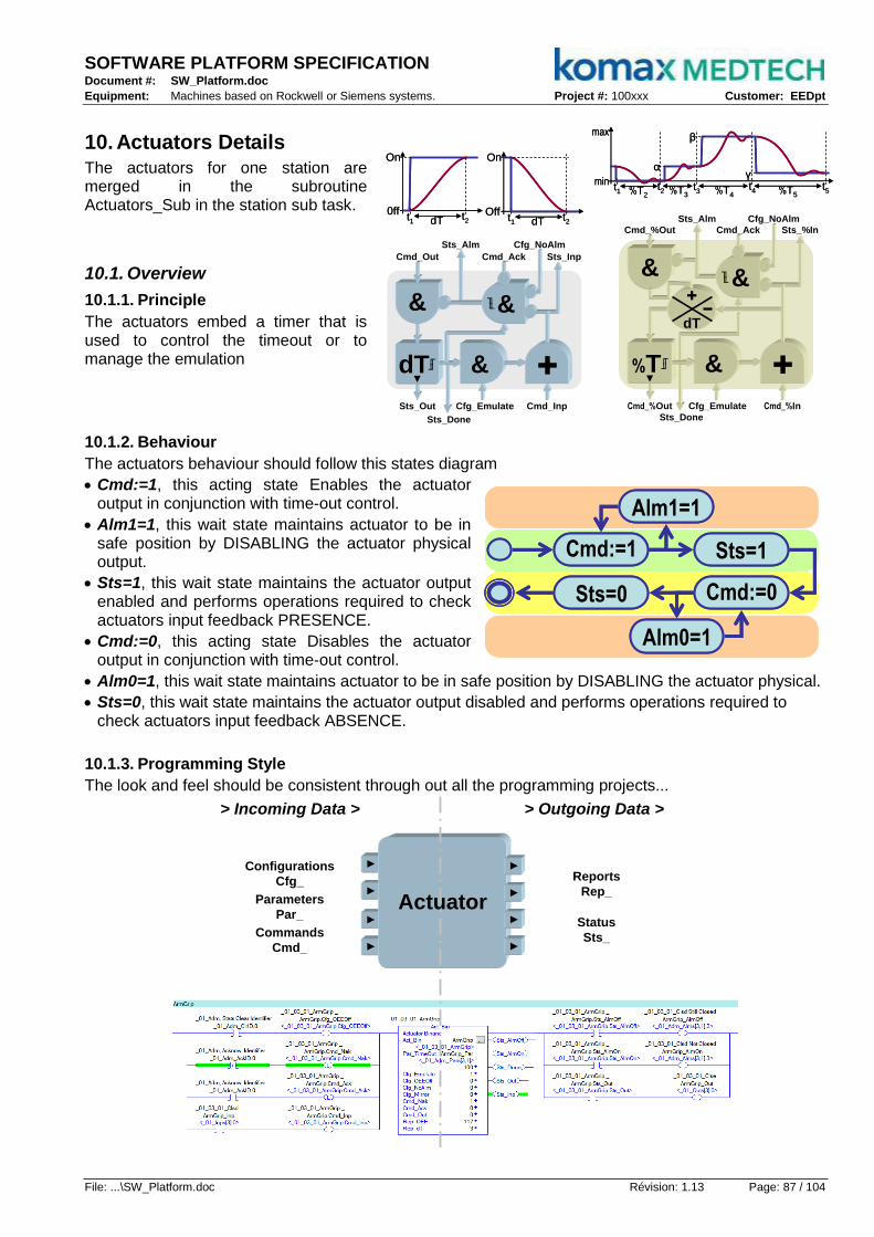
SOFTWARE PLATFORM SPECIFICATION Document #: SW_Platform.doc
Equipment: Machines based on Rockwell or Siemens systems. Project #: 100xxx Customer: EEDpt
File: ...\SW_Platform.doc Révision: 1.13 Page: 87 / 104
10. Actuators Details The actuators for one station are merged in the subroutine Actuators_Sub in the station sub task.
10.1. Overview
10.1.1. Principle
The actuators embed a timer that is used to control the timeout or to manage the emulation
10.1.2. Behaviour
The actuators behaviour should follow this states diagram
Cmd:=1, this acting state Enables the actuator output in conjunction with time-out control.
Alm1=1, this wait state maintains actuator to be in safe position by DISABLING the actuator physical output.
Sts=1, this wait state maintains the actuator output enabled and performs operations required to check actuators input feedback PRESENCE.
Cmd:=0, this acting state Disables the actuator output in conjunction with time-out control.
Alm0=1, this wait state maintains actuator to be in safe position by DISABLING the actuator physical.
Sts=0, this wait state maintains the actuator output disabled and performs operations required to check actuators input feedback ABSENCE.
10.1.3. Programming Style
The look and feel should be consistent through out all the programming projects...
▼▼
▼▼
▼▼
▼▼
Commands
Cmd_
Configurations
Cfg_
Parameters
Par_
Reports
Rep_
Status
Sts_
Actuator
▼▼
▼▼
▼▼
▼▼
> Incoming Data > > Outgoing Data >
dT►
╓╜dT►
╓╜ &
& &╖╙&╖╙
Cmd_Out
Sts_Alm
Sts_Inp
Sts_Out Cmd_InpCfg_Emulate
Sts_Done
Cmd_Ack
Cfg_NoAlm
%T ►
╓╜%T ►
╓╜ &
Sts_Alm
Cmd_%Out Cmd_%InCfg_Emulate
Sts_Done
dT
Cmd_%Out
&
Sts_%InCmd_Ack
&╖╙&╖╙
Cfg_NoAlm
0ff
On
t1 t2dT0ff
On
t1 t2dTOff
On
t1 t2dTOff
On
t1 t2dT
α
β
t1 t2%T2
min
max
t3 t4 t5
γ
%T3 %T4 %T5
α
β
t1 t2%T2
min
max
t3 t4 t5
γ
%T3 %T4 %T5Cmd_On
Cmd_Off
Sts_Off
Alm_On
Alm_Off
Sts_On
Cmd_On
Cmd_Off
Sts_Off
Alm_On
Alm_Off
Sts_On
Cmd:=1
Cmd:=0Sts=0
Alm1=1
Alm0=1
Sts=1Cmd:=1
Cmd:=0Sts=0
Alm1=1
Alm0=1
Sts=1Cmd:=1
Cmd:=0Sts=0
Alm1=1
Alm0=1
Sts=1

SOFTWARE PLATFORM SPECIFICATION Document #: SW_Platform.doc
Equipment: Machines based on Rockwell or Siemens systems. Project #: 100xxx Customer: EEDpt
File: ...\SW_Platform.doc Révision: 1.13 Page: 88 / 104
10.2. Binary
Act_Bin is states control for binary component (cylinder, gate, conveyor, etc...)
10.2.1. Single Solenoid - Single Sensor
▼ ▼▲ ▲
Grip
▼ ▲ ▼ ▲
▼ ▼▲ ▲
Grip
▼ ▲ ▼ ▲
10.2.2. Single Solenoid - Double Sensors
▼ ▼ ▲ ▲
Down
▼ ▲ ▼ ▲
▼ ▼ ▲ ▲
Down
▼ ▲ ▼ ▲
10.2.3. Double Solenoids - Double Sensors
▼▼
▲▲
▼▼
▲▲
Pic
k
▼▲
▼▲
Pla
ce
▼▲
▼▲
▼▼
▲▲
▼▼
▲▲
Pic
k
▼▲
▼▲
Pla
ce
▼▲
▼▲
10.2.4. Operator Button with Lamp
StopStop
10.2.5. Emergency Stop

SOFTWARE PLATFORM SPECIFICATION Document #: SW_Platform.doc
Equipment: Machines based on Rockwell or Siemens systems. Project #: 100xxx Customer: EEDpt
File: ...\SW_Platform.doc Révision: 1.13 Page: 89 / 104
10.2.6. Light / Lamp
10.2.7. Recipe Confirm
10.2.8. Batch Confirm

SOFTWARE PLATFORM SPECIFICATION Document #: SW_Platform.doc
Equipment: Machines based on Rockwell or Siemens systems. Project #: 100xxx Customer: EEDpt
File: ...\SW_Platform.doc Révision: 1.13 Page: 90 / 104
10.3. Camodulo
Act_Cam is states control for camshaft component (angular axis, came follower, etc...)
10.3.1. Rotary Indexer
10.3.2. Came Follower

SOFTWARE PLATFORM SPECIFICATION Document #: SW_Platform.doc
Equipment: Machines based on Rockwell or Siemens systems. Project #: 100xxx Customer: EEDpt
File: ...\SW_Platform.doc Révision: 1.13 Page: 91 / 104
10.3.3. Master Came
10.4. Numeric
Act_Num is states control for numeric component. (linear axis, heater, flow meter, etc...)
10.4.1. Probe
10.4.2. Axis

SOFTWARE PLATFORM SPECIFICATION Document #: SW_Platform.doc
Equipment: Machines based on Rockwell or Siemens systems. Project #: 100xxx Customer: EEDpt
File: ...\SW_Platform.doc Révision: 1.13 Page: 92 / 104
10.5. Pulse
Act_Pls is states control for hysteretic component.(feeder level, flip-flop, tick control, etc...).
10.5.1. Flip-Flop
10.5.2. Feeder Level

SOFTWARE PLATFORM SPECIFICATION Document #: SW_Platform.doc
Equipment: Machines based on Rockwell or Siemens systems. Project #: 100xxx Customer: EEDpt
File: ...\SW_Platform.doc Révision: 1.13 Page: 93 / 104
A. Appendices
A.1. Overall Model
_01_M
ach
ine, P
hysic
al It
em
s (
ele
ctr
ic &
pn
eu
mati
c)
_01_M
ach
ine
_01_00_S
tati
on
_01_00_00_
Actu
at,
_01_
Ad
m_
Pu
bli
c D
ata
In
/Ou
t
_M
od
es
& S
tate
s
Cm
dS
ts
Cm
dS
ts
Cm
dS
ts
Cm
dS
ts
Ou
tpu
tIn
pu
t
_01_00_01_
Actu
at,
Cm
dS
ts
Ou
tpu
tIn
pu
t
_01_01_S
tati
on
_01_01_00_
Actu
at,
Cm
dS
ts
Cm
dS
ts
Cm
dS
ts
Ou
tpu
tIn
pu
t
_01_01_01_
Actu
at,
Cm
dS
ts
Ou
tpu
tIn
pu
t
Netw
ork
ed
Man
ag
ers
_01_
Ad
m.A
ctu
ato
rs_
00
_S
afe
Gu
ard
_01
_A
lm_
Bu
zz
_02
_A
lm_
Wh
ite
_03
_A
lm_
Gre
en
_04
_A
lm_
Am
be
r_
05
_A
lm_
Re
d_
06
_B
ut_
Sto
p_
07
_B
ut_
Sta
rt_
08
_B
ut_
Jo
g-
_09
_B
ut_
Jo
g+
Act_
Bin
Act_
Cam
Act_
Nu
m
Act_
Pls
Man
_T
rack
Man
_N
est
Man
_P
rog
Man
_A
dm
Ob
jects
Cla
sse
s
Program_Logic Actuators_Sub
Fil
es
_01_
Ad
m.A
lmS
can
Latecomer_Sub
Trackser_Sub
Motions_Sub
Visions_Sub

SOFTWARE PLATFORM SPECIFICATION Document #: SW_Platform.doc
Equipment: Machines based on Rockwell or Siemens systems. Project #: 100xxx Customer: EEDpt
File: ...\SW_Platform.doc Révision: 1.13 Page: 94 / 104
A.2. Structured Text
Machine Example :
(* PROGRAM HEADER, Check _01_Adm_SafeID AND Update Status_Abort *)
Prog.Cfg_ActExe:=_01_Adm_SafeID.0; Track.Sts_Abort:=(Prog.Cfg_Safe & Prog.Sts_State.2 & Prog.Sts_Abort);
(* Call Manager_Program, Call Manager_Tracks AND IF State_Once THEN First Sequence *)
Mgr_Prog(Prog);
Mgr_Track(Track,Prog,1,10800);
Track.Cfg_ConsOff:=_01_Adm_ClrID.0; Track.Cfg_OEEOff:=_01_Adm_ClrID.0;
IF _01_Adm_AckID.0 & NOT Prog.Sts_NoAlm THEN Prog.Cmd_State.0:=1; END_IF;
IF Prog.Sts_StateOns THEN
IF Prog.Sts_State.0 THEN Prog.Sts_Seq:=01; END_IF;
IF Prog.Sts_State.1 THEN Prog.Sts_Seq:=11; END_IF;
IF Prog.Sts_State.2 THEN Prog.Sts_Seq:=21; END_IF;
END_IF;
(* PROGRAM SEQUENCER, Process Control *)
CASE Prog.Sts_Seq OF
01: (* Abort every process station *)
IF Prog.Sts_SeqOns THEN _01_01_Prog.Cmd_State:=1; _01_02_Prog.Cmd_State:=1; _01_03_Prog.Cmd_State:=1;
_01_04_Prog.Cmd_State:=1; Prog.Sts_Safe:=0; END_IF;
IF NOT Prog.Sts_SeqOns & _01_01_Prog.Sts_Idle & _01_02_Prog.Sts_Idle & _01_03_Prog.Sts_Idle &
_01_04_Prog.Sts_Idle & Prog.Sts_SeqExe THEN Prog.Cmd_Seq:=2; END_IF;
02: (* Abort BaseFibro *)
IF Prog.Sts_SeqOns THEN _01_00_Prog.Cmd_State:=1; END_IF;
IF NOT Prog.Sts_SeqOns & _01_00_Prog.Sts_Idle & Prog.Sts_SeqExe THEN Prog.Sts_Safe:=1; Prog.Sts_Idle:=1;END_IF;
11: (* Config Tracks vs Mode *)
JSR(ProgMode_Sub); Prog.Cmd_Seq:=12;
12: (* Reset every process station *)
IF Prog.Sts_SeqOns THEN _01_01_Prog.Cmd_State:=2; _01_02_Prog.Cmd_State:=2; _01_03_Prog.Cmd_State:=2;
_01_04_Prog.Cmd_State:=2; Prog.Sts_Safe:=0; END_IF;
IF NOT Prog.Sts_SeqOns & _01_01_Prog.Sts_Idle & _01_02_Prog.Sts_Idle & _01_03_Prog.Sts_Idle &
_01_04_Prog.Sts_Idle & Prog.Sts_SeqExe THEN Prog.Cmd_Seq:=13; END_IF;
13: (* Reset BaseFibro *)
IF Prog.Sts_SeqOns THEN _01_00_Prog.Cmd_State:=2; END_IF;
IF NOT Prog.Sts_SeqOns & _01_00_Prog.Sts_Idle & Prog.Sts_SeqExe THEN Prog.Sts_Safe:=1; Prog.Sts_Idle:=1;END_IF;
21: (* Exec every process station *)
IF Prog.Sts_SeqOns THEN _01_01_Prog.Cmd_State:=4; _01_02_Prog.Cmd_State:=4; _01_03_Prog.Cmd_State:=4;
_01_04_Prog.Cmd_State:=4; Prog.Sts_Safe:=0; END_IF;
IF NOT Prog.Sts_SeqOns & _01_01_Prog.Sts_Idle & _01_02_Prog.Sts_Idle & _01_03_Prog.Sts_Idle &
_01_04_Prog.Sts_Idle & Prog.Sts_SeqExe THEN Prog.Cmd_Seq:=22; END_IF;
22: (* Exec BaseFibro *)
IF Prog.Sts_SeqOns THEN _01_00_Prog.Cmd_State:=4; END_IF;
IF NOT Prog.Sts_SeqOns & _01_00_Prog.Sts_Idle & Prog.Sts_SeqExe THEN Prog.Sts_Safe:=1; Prog.Sts_Idle:=1;END_IF;
IF Prog.Sts_Idle THEN
IF NOT Prog.Sts_Abort THEN Track.Sts_Good:=1; END_IF;
IF _01_03_Nest0.Sts_Abort THEN _01_Adm_Oper.Sts_AbortID.0:=1; _01_Adm_Shift.Sts_AbortID.0:=1;
_01_Adm_Batch.Sts_AbortID.0:=1; END_IF;
IF _01_03_Nest0.Sts_Good THEN _01_Adm_Oper.Sts_GoodID.0:=1; _01_Adm_Shift.Sts_GoodID.0:=1;
_01_Adm_Batch.Sts_GoodID.0:=1; END_IF;
IF _01_03_Nest1.Sts_Abort THEN _01_Adm_Oper.Sts_AbortID.1:=1; _01_Adm_Shift.Sts_AbortID.1:=1;
_01_Adm_Batch.Sts_AbortID.1:=1; END_IF;
IF _01_03_Nest1.Sts_Good THEN _01_Adm_Oper.Sts_GoodID.1:=1; _01_Adm_Shift.Sts_GoodID.1:=1;
_01_Adm_Batch.Sts_GoodID.1:=1; END_IF;
END_IF;
ELSE Prog.Sts_Seq:=0;
END_CASE;
(* PROGRAM FOOTER, IF Config_ActExe THEN Merge every reuiqred Actuators Alarms to update Status_NoAlarm *)
IF Prog.Cfg_ActExe THEN Prog.Sts_NoAlm:=(_01_00_Prog.Sts_NoAlm OR NOT _01_00_Prog.Cfg_ActExe) &
(_01_01_Prog.Sts_NoAlm OR NOT _01_01_Prog.Cfg_ActExe) &
(_01_02_Prog.Sts_NoAlm OR NOT _01_02_Prog.Cfg_ActExe) &
(_01_03_Prog.Sts_NoAlm OR NOT _01_03_Prog.Cfg_ActExe) &
(_01_04_Prog.Sts_NoAlm OR NOT _01_04_Prog.Cfg_ActExe);
END_IF;
(* IF NO Status_NoAlarm THEN check each station IDLE or Alarm to Set Sts_Idle (i.e. alarm pending management) *)
IF NOT Prog.Sts_NoAlm & (NOT _01_00_Prog.Sts_NoAlm OR _01_00_Prog.Sts_Idle) &
(NOT _01_01_Prog.Sts_NoAlm OR _01_01_Prog.Sts_Idle) &
(NOT _01_02_Prog.Sts_NoAlm OR _01_02_Prog.Sts_Idle) &
(NOT _01_03_Prog.Sts_NoAlm OR _01_03_Prog.Sts_Idle) &
(NOT _01_04_Prog.Sts_NoAlm OR _01_04_Prog.Sts_Idle) THEN Prog.Sts_Idle:=1;
END_IF;

SOFTWARE PLATFORM SPECIFICATION Document #: SW_Platform.doc
Equipment: Machines based on Rockwell or Siemens systems. Project #: 100xxx Customer: EEDpt
File: ...\SW_Platform.doc Révision: 1.13 Page: 95 / 104
Station Example :
(* PROGRAM HEADER, Check _01_Adm_SafeID AND Update Status_Abort *)
Prog.Cfg_ActExe:=1; Prog.Cfg_Emulate:=1; Prog.Cfg_Safe:=_01_Adm_SafeID.0;
Track0.Sts_Abort:=(Prog.Cfg_Safe & Prog.Sts_State.2 & Prog.Sts_Abort); Track1.Sts_Abort:=Track0.Sts_Abort;
Nest0.Sts_Abort:=Track0.Sts_Abort; Nest1.Sts_Abort:=Track0.Sts_Abort;
(* Call Manager_Program, Call Manager_Tracks AND IF State_Once THEN First Sequence *)
Mgr_Prog(Prog);
Mgr_Track(Track0,Prog,3,9000); Mgr_Nest(Nest0,Prog,_01_Adm_NestID,_01_Adm_NestInt);
Mgr_Track(Track1,Prog,3,9000); Mgr_Nest(Nest1,Prog,_01_Adm_NestID,_01_Adm_NestInt);
Track0.Cfg_ConsOff:=_01_Adm_ClrID.0; Track0.Cfg_OEEOff:=_01_Adm_ClrID.0; Nest0.Cfg_OEEOff:=_01_Adm_ClrID.0;
Track1.Cfg_ConsOff:=_01_Adm_ClrID.0; Track1.Cfg_OEEOff:=_01_Adm_ClrID.0; Nest1.Cfg_OEEOff:=_01_Adm_ClrID.0;
IF _01_Adm_AckID.0 & NOT Prog.Sts_NoAlm THEN Prog.Cmd_State.0:=1; END_IF;
IF Prog.Sts_StateOns THEN
IF Prog.Sts_State.0 THEN Prog.Sts_Seq:=1; END_IF;
IF NOT Prog.Sts_State.0 THEN Prog.Sts_Seq:=2; END_IF;
END_IF;
(* PROGRAM SEQUENCER, Process Control *)
CASE Prog.Sts_Seq OF
01: (* Disable Feeder + Close Gate *)
IF Prog.Sts_SeqOns THEN BodyGate.Cmd_Out:=0; BodyFeed.Cmd_Out:=0; Prog.Sts_Safe:=0; END_IF;
IF Prog.Sts_SeqExe & NOT BodyGate.Sts_Inp & NOT BodyFeed.Sts_Inp THEN Prog.Cmd_Seq:=8; END_IF;
02: (* Enable Feeder + Open Gate *)
IF Prog.Sts_SeqOns THEN BodyGate.Cmd_Out:=1; BodyFeed.Cmd_Out:=1; END_IF;
IF Prog.Sts_SeqExe & BodyGate.Sts_Inp & BodyFeed.Sts_Inp THEN Prog.Cmd_Seq:=3; END_IF;
03: (* Arm Down on pick Close Gate *)
IF Prog.Sts_SeqOns THEN ArmDown.Cmd_Out:=1; BodyGate.Cmd_Out:=0; END_IF;
IF Prog.Sts_SeqExe & ArmDown.Sts_Inp & NOT BodyGate.Sts_Inp THEN Prog.Cmd_Seq:=4; END_IF;
04: (* Close Gripper on pick *)
IF Prog.Sts_SeqOns THEN ArmGrip0.Cmd_Out:=(Track0.Cfg_Enable & NOT Nest0.Sts_Nesty); END_IF;
IF Prog.Sts_SeqOns THEN ArmGrip1.Cmd_Out:=(Track1.Cfg_Enable & NOT Nest1.Sts_Nesty); END_IF;
IF Prog.Sts_SeqExe & (ArmGrip0.Sts_Inp OR NOT ArmGrip0.Cmd_Out) &
(ArmGrip1.Sts_Inp OR NOT ArmGrip1.Cmd_Out) THEN Prog.Cmd_Seq:=5; END_IF;
05: (* Arm Up on pick *)
IF Prog.Sts_SeqOns THEN ArmDown.Cmd_Out:=0; END_IF;
IF Prog.Sts_SeqExe & NOT ArmDown.Sts_Inp THEN Prog.Cmd_Seq:=6; END_IF;
06: (* Arm Up to place *)
IF Prog.Sts_SeqOns THEN ArmMotion.Cmd_Sp.6:=1; Prog.Sts_Safe:=0; END_IF;
IF NOT Prog.Sts_SeqOns & ArmMotion.Sts_Inp THEN Prog.Cmd_Seq:=7; END_IF;
07: (* Armp Down on place *)
IF Prog.Sts_SeqOns THEN ArmDown.Cmd_Out:=1; END_IF;
IF Prog.Sts_SeqExe & ArmDown.Sts_Inp THEN Prog.Cmd_Seq:=8; END_IF;
08: (* Open Gripper *)
IF Prog.Sts_SeqOns THEN ArmGrip0.Cmd_Out:=0; ArmGrip1.Cmd_Out:=0; END_IF;
IF Prog.Sts_SeqExe & NOT ArmGrip0.Sts_Inp & NOT ArmGrip1.Sts_Inp THEN Prog.Cmd_Seq:=9; END_IF;
09: (* Arm Up on place *)
IF Prog.Sts_SeqOns THEN ArmDown.Cmd_Out:=0; END_IF;
IF Prog.Sts_SeqExe & NOT ArmDown.Sts_Inp THEN Prog.Cmd_Seq:=10; END_IF;
10: (* Arm Up to pick *)
IF Prog.Sts_SeqOns THEN ArmMotion.Cmd_Sp.10:=1; END_IF;
IF NOT Prog.Sts_SeqOns & ArmMotion.Sts_Inp THEN Prog.Sts_Safe:=1; Prog.Sts_Idle:=1; END_IF;
IF Prog.Sts_Idle & Prog.Sts_State.2 THEN Track0.Sts_Good:=(Track0.Cfg_Enable & NOT Prog.Sts_Abort);
Nest0.Sts_Good:=Track0.Sts_Good; Nest0.Sts_Nesty:=Track0.Sts_Good; END_IF;
IF Prog.Sts_Idle & Prog.Sts_State.2 THEN Track1.Sts_Good:=(Track1.Cfg_Enable & NOT Prog.Sts_Abort);
Nest1.Sts_Good:=Track1.Sts_Good; Nest1.Sts_Nesty:=Track1.Sts_Good; END_IF;
ELSE Prog.Sts_Seq:=0;
END_CASE;
(* PROGRAM FOOTER, IF Config_ActExe THEN Call Actuators_Sub AND Merge Actuators Alarms to update Status_NoAlarm *)
IF Prog.Cfg_ActExe THEN
JSR(Actuators_Sub);
Prog.Sts_NoAlm:=NOT ArmGrip0.Sts_AlmOff & NOT ArmGrip0.Sts_AlmOn & NOT ArmGrip1.Sts_AlmOff &
NOT ArmGrip1.Sts_AlmOn & NOT ArmDown.Sts_AlmOff & NOT ArmDown.Sts_AlmOn &
NOT ArmMotion.Sts_AlmOff & NOT ArmMotion.Sts_AlmOn & NOT BodyGate.Sts_AlmOff &
NOT BodyGate.Sts_AlmOn & NOT BodyFeed.Sts_AlmOff & NOT BodyFeed.Sts_AlmOn;
END_IF;
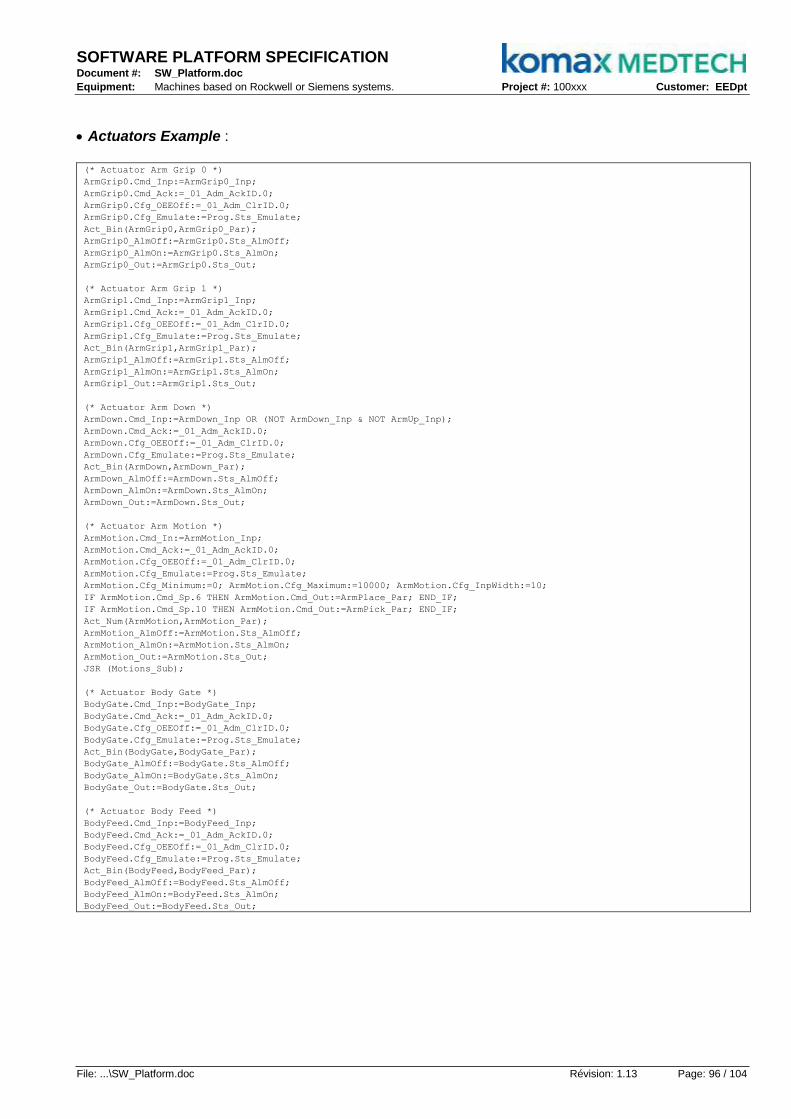
SOFTWARE PLATFORM SPECIFICATION Document #: SW_Platform.doc
Equipment: Machines based on Rockwell or Siemens systems. Project #: 100xxx Customer: EEDpt
File: ...\SW_Platform.doc Révision: 1.13 Page: 96 / 104
Actuators Example :
(* Actuator Arm Grip 0 *)
ArmGrip0.Cmd_Inp:=ArmGrip0_Inp;
ArmGrip0.Cmd_Ack:=_01_Adm_AckID.0;
ArmGrip0.Cfg_OEEOff:=_01_Adm_ClrID.0;
ArmGrip0.Cfg_Emulate:=Prog.Sts_Emulate;
Act_Bin(ArmGrip0,ArmGrip0_Par);
ArmGrip0_AlmOff:=ArmGrip0.Sts_AlmOff;
ArmGrip0_AlmOn:=ArmGrip0.Sts_AlmOn;
ArmGrip0_Out:=ArmGrip0.Sts_Out;
(* Actuator Arm Grip 1 *)
ArmGrip1.Cmd_Inp:=ArmGrip1_Inp;
ArmGrip1.Cmd_Ack:=_01_Adm_AckID.0;
ArmGrip1.Cfg_OEEOff:=_01_Adm_ClrID.0;
ArmGrip1.Cfg_Emulate:=Prog.Sts_Emulate;
Act_Bin(ArmGrip1,ArmGrip1_Par);
ArmGrip1_AlmOff:=ArmGrip1.Sts_AlmOff;
ArmGrip1_AlmOn:=ArmGrip1.Sts_AlmOn;
ArmGrip1_Out:=ArmGrip1.Sts_Out;
(* Actuator Arm Down *)
ArmDown.Cmd_Inp:=ArmDown_Inp OR (NOT ArmDown_Inp & NOT ArmUp_Inp);
ArmDown.Cmd_Ack:=_01_Adm_AckID.0;
ArmDown.Cfg_OEEOff:=_01_Adm_ClrID.0;
ArmDown.Cfg_Emulate:=Prog.Sts_Emulate;
Act_Bin(ArmDown,ArmDown_Par);
ArmDown_AlmOff:=ArmDown.Sts_AlmOff;
ArmDown_AlmOn:=ArmDown.Sts_AlmOn;
ArmDown_Out:=ArmDown.Sts_Out;
(* Actuator Arm Motion *)
ArmMotion.Cmd_In:=ArmMotion_Inp;
ArmMotion.Cmd_Ack:=_01_Adm_AckID.0;
ArmMotion.Cfg_OEEOff:=_01_Adm_ClrID.0;
ArmMotion.Cfg_Emulate:=Prog.Sts_Emulate;
ArmMotion.Cfg_Minimum:=0; ArmMotion.Cfg_Maximum:=10000; ArmMotion.Cfg_InpWidth:=10;
IF ArmMotion.Cmd_Sp.6 THEN ArmMotion.Cmd_Out:=ArmPlace_Par; END_IF;
IF ArmMotion.Cmd_Sp.10 THEN ArmMotion.Cmd_Out:=ArmPick_Par; END_IF;
Act_Num(ArmMotion,ArmMotion_Par);
ArmMotion_AlmOff:=ArmMotion.Sts_AlmOff;
ArmMotion_AlmOn:=ArmMotion.Sts_AlmOn;
ArmMotion_Out:=ArmMotion.Sts_Out;
JSR (Motions_Sub);
(* Actuator Body Gate *)
BodyGate.Cmd_Inp:=BodyGate_Inp;
BodyGate.Cmd_Ack:=_01_Adm_AckID.0;
BodyGate.Cfg_OEEOff:=_01_Adm_ClrID.0;
BodyGate.Cfg_Emulate:=Prog.Sts_Emulate;
Act_Bin(BodyGate,BodyGate_Par);
BodyGate_AlmOff:=BodyGate.Sts_AlmOff;
BodyGate_AlmOn:=BodyGate.Sts_AlmOn;
BodyGate_Out:=BodyGate.Sts_Out;
(* Actuator Body Feed *)
BodyFeed.Cmd_Inp:=BodyFeed_Inp;
BodyFeed.Cmd_Ack:=_01_Adm_AckID.0;
BodyFeed.Cfg_OEEOff:=_01_Adm_ClrID.0;
BodyFeed.Cfg_Emulate:=Prog.Sts_Emulate;
Act_Bin(BodyFeed,BodyFeed_Par);
BodyFeed_AlmOff:=BodyFeed.Sts_AlmOff;
BodyFeed_AlmOn:=BodyFeed.Sts_AlmOn;
BodyFeed_Out:=BodyFeed.Sts_Out;
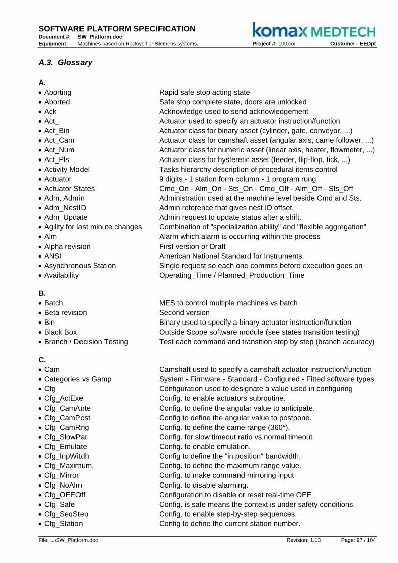
SOFTWARE PLATFORM SPECIFICATION Document #: SW_Platform.doc
Equipment: Machines based on Rockwell or Siemens systems. Project #: 100xxx Customer: EEDpt
File: ...\SW_Platform.doc Révision: 1.13 Page: 97 / 104
A.3. Glossary
A.
Aborting Rapid safe stop acting state
Aborted Safe stop complete state, doors are unlocked
Ack Acknowledge used to send acknowledgement
Act_ Actuator used to specify an actuator instruction/function
Act_Bin Actuator class for binary asset (cylinder, gate, conveyor, ...)
Act_Cam Actuator class for camshaft asset (angular axis, came follower, ...)
Act_Num Actuator class for numeric asset (linear axis, heater, flowmeter, ...)
Act_Pls Actuator class for hysteretic asset (feeder, flip-flop, tick, ...)
Activity Model Tasks hierarchy description of procedural items control
Actuator 9 digits - 1 station form column - 1 program rung
Actuator States Cmd_On - Alm_On - Sts_On - Cmd_Off - Alm_Off - Sts_Off
Adm, Admin Administration used at the machine level beside Cmd and Sts.
Adm_NestID Admin reference that gives nest ID offset.
Adm_Update Admin request to update status after a shift.
Agility for last minute changes Combination of "specialization ability" and "flexible aggregation"
Alm Alarm which alarm is occurring within the process
Alpha revision First version or Draft
ANSI American National Standard for Instruments.
Asynchronous Station Single request so each one commits before execution goes on
Availability Operating_Time / Planned_Production_Time
B.
Batch MES to control multiple machines vs batch
Beta revision Second version
Bin Binary used to specify a binary actuator instruction/function
Black Box Outside Scope software module (see states transition testing)
Branch / Decision Testing Test each command and transition step by step (branch accuracy)
C.
Cam Camshaft used to specify a camshaft actuator instruction/function
Categories vs Gamp System - Firmware - Standard - Configured - Fitted software types
Cfg Configuration used to designate a value used in configuring
Cfg_ActExe Config. to enable actuators subroutine.
Cfg_CamAnte Config. to define the angular value to anticipate.
Cfg_CamPost Config to define the angular value to postpone.
Cfg_CamRng Config. to define the came range (360°).
Cfg_SlowPar Config. for slow timeout ratio vs normal timeout.
Cfg_Emulate Config. to enable emulation.
Cfg_InpWitdh Config to define the "in position" bandwidth.
Cfg_Maximum, Config. to define the maximum range value.
Cfg_Mirror Config. to make command mirroring input
Cfg_NoAlm Config. to disable alarming.
Cfg_OEEOff Configuration to disable or reset real-time OEE
Cfg_Safe Config. is safe means the context is under safety conditions.
Cfg_SeqStep Config. to enable step-by-step sequences.
Cfg_Station Config to define the current station number.
SOFTWARE PLATFORM SPECIFICATION Document #: SW_Platform.doc
Equipment: Machines based on Rockwell or Siemens systems. Project #: 100xxx Customer: EEDpt
File: ...\SW_Platform.doc Révision: 1.13 Page: 98 / 104
Cfg_TrackQty Configuration to define tracks quantity per station
Change Control Software change traceability (revisions numbering)
Check list "Dry-Run" check - "Test-Up" check - "To Do" list
Class diagram Represent main objects and/or interactions in the application
Clr Clear used to designate a command used to clear
Cmd To command input of the instruction/function
Cmd_Ack Command to acknowledge pending alarm.
Cmd_Hold Command to request an immediate motion stop.
Cmd_Inn Command to read from physical input.
Cmd_Inp Command to read from physical input.
Cmd_Loop Command to request a full revolution cycle.
Cmd_Nak Reverse command to acknowledge pending alarm.
Cmd_Out Command to enable/disable output.
Cmd_SeqOns Command one shot under Step-by-Step.
Cmd_Sp Command to switch between different setpoints.
Cmd_State Command to request state change:
Configuration Software modules specification
Code 2nd development phase completed with configuration and code
Ctl Control, Complex PLC 's data structures used to control PLC's
Ctr Counter used to accumulate or increment any type of value
D.
Debug 4th development phase completed with modular testing
Data Flow Testing Test interactions between components connected by data flow
Data In Configuration, Parameters, Options, ...
Data Out Reports, Counters, Tracks, Nests, Effectiveness, ...
DataType Could be Boolean, Integer, Real, String, etc...
Design 1st development phase completed with specification
Diagnostics / Effectiveness real-time OEE on each items to predict and diagnose failures
Domain Applied to tags as public (global) or private (local)
E.
E2ASY Emulation-Effectiveness-Agility-Simplicity-Yeswe comply.
Effectiveness / Diagnostics real-time OEE on each items to predict and diagnose failures
Emulation for early de-risking to pre-test process sequences as soon as possible
E-Stop Emergency stop initiates a Abort request
Execute Running dual state (machine is processing parts)
Extreme Programming Writing the test procedure at the same time the function is coded
F. G. H.
Fail Safe Automatic & safe ability to compensate a failure
FDS Functional Design Specification
Gamp Good Automation Manufacturing Practices.
Gold Release revision Qualified version
HDS Hardware Design Specification
Held Temporary stop complete, wait for operator action
Hierarchy Representation of "above", "below" or "at the same level as" items
HMI Human Machine Interface
Holding Temporary stop acting state, usually to require operator action

SOFTWARE PLATFORM SPECIFICATION Document #: SW_Platform.doc
Equipment: Machines based on Rockwell or Siemens systems. Project #: 100xxx Customer: EEDpt
File: ...\SW_Platform.doc Révision: 1.13 Page: 99 / 104
I.
...ID Identifier used to merge some Boolean status within an integer
Idle Homing complete state, ready to start !
IEC International Electrotechnical Commission
IEC-61131-3 Normalisation des langages de programmations
IEEE Institute of Electrical and Electronics Engineers
Imperative Logic Considered as an algorithmic declarative programming
Inp Input, Real-time data used to drive the process
Interface Data structure to interconnect software items (object)
IQ Installation Qualification
ISA-S88-01 (IEC-61512-1) Batch Control, Models and Terminology.
ISA-S88-02 (IEC-61512-2) Batch Control, Data Structure & Guideline for Languages.
ISA-S88-05 (IEC-61512-5) Batch Control, Automated Equipment Control Models.
ISA-S88, Commissioning Models and Commissioning / Qualification Mapping.
ISA-TR88.00.02 Machine and Unit States: ISA-S88 Implementation Example.
ISA Instrument Society of America.
ISO International Organization for Standardization
ISO 13849-1 Safety of machinery – Part 1. General principles for design.
ISPE International Society for Pharmaceutical Engineering.
J. K. L.
Jog- In manual mode, negative slow motion request
Jog+ In manual mode, positive slow motion request
Line 1 project title - 1 directory - 1 PLC
Log User Login status of machine.
Logic Could be Imperative or Sequencing Logic
M. N.
Machine 3 digits - 1 file - 1 PLC's task program
Machine Modes Producing - Maintenance - Manual - Purge - Dry cycle - etc...
Machine States Aborting - Aborted - Stopping - Stopped - Resetting - Idle - etc...
MainType Could be machine or sub-machine
Main_ID should be between _00 to _99.
MainName the convenient machine name description.
MaindT#### Ideal expected time response.
Man Manager used to specify a manager instruction/function
MES Manufacturing Execution System
Mgr_Adm Manager for machine statistics
Mgr_Nest Manager for nest statistics
Mgr_Prog Manager for program (mode, states & sequences)
Mgr_Track Manager for track statistics
Mode Mode of the process within the machine
Model A representation of components and their relationships
Modular Testing To test software modules (see Testing).
Module Software Every PLC's explorer files (see POU).
Module Specification Software Configuration
Nest Fixture side or up
Num Numeric used to specify a numeric actuator instruction/function

SOFTWARE PLATFORM SPECIFICATION Document #: SW_Platform.doc
Equipment: Machines based on Rockwell or Siemens systems. Project #: 100xxx Customer: EEDpt
File: ...\SW_Platform.doc Révision: 1.13 Page: 100 / 104
O.
Object diagram UML diagram that shows the structure of a modelled system.
OEE Overall Equipment Effectiveness
OMAC Organization for Machine Automation & Control
OOP Object Oriented Programming (see UML)
OQ Operational Qualification
Out Output Real-time data driven from the process
P. Q.
PackML Packaging Modeling Language.
Par Parameters are variables that are from an external source
Par_MaxCons Parameter to define consecutive maximum.
Par_TimeIdeal Parameter to define execute ideal cycle time.
Par_TmrOff Parameter to define down threshold delay.
Par_TmrOn Parameter to define up threshold delay.
Par_TimeOut Parameter to define movement timeout.
Performance Total_Pieces / (Operating_Time x Ideal_Run_Rate / 60)
Physics The hierarchy's process tree complying to P&ID tagging
Physical Model A description of physical assets involved in manufacturing
Platform PLC's architecture, coding rules and related user interface
PLC Program Logic Controller
Pls Pulse used to specify a pulse (flip-flop) actuator
POU Program Organization Unit (PLC's Explorer Hierarchy)
PQ Performance Qualification
Procedural Model A logic description required to accomplish a batch
Process Model A batch description required to manufacture something
Prog - Program Task dedicated to a machine and / or station
Qualification Ensure the performance correlates the specification
Quality Good_Pieces / Total_Pieces
R.
RAD Rapid Application Development
Recipe Name of active parameters and camshafts collection
RecipID ID of active parameters and camshafts collection
Recips Storable and restorable parameters and camshafts collections
References PLC's supplier guide lines
Release Candidate Revision Ready to start testing
Rep Reported value designates a value
Rep_Ante Report to indicate current anticipated window angle
Rep_Availability Report to view current OEE availability.
Rep_Consec Report to view current consecutive value.
Rep_CtrAlm Report to view alarming states quantity.
Rep_CtrAbort Report to view aborting sequence quantity.
Rep_CtrGood Report to view good sequence quantity.
Rep_CtrExec Report to view executing sequence quantity.
Rep_CtrTotal Report to view total sequence quantity.
Rep_dT Report to view acting state duration value.
Rep_OEE Report to view current real time OEE value.
Rep_Performance Report to view current OEE performance.
Rep_Post Report to indicate current postponed window angle
SOFTWARE PLATFORM SPECIFICATION Document #: SW_Platform.doc
Equipment: Machines based on Rockwell or Siemens systems. Project #: 100xxx Customer: EEDpt
File: ...\SW_Platform.doc Révision: 1.13 Page: 101 / 104
Rep_Quality Report to view current OEE quality.
Rep_TmrAbort Report to view aborting time accumulation.
Rep_TmrExec Report to view executing time accumulation.
Rep_TmrTotal Report to view total time accumulation.
Resetting Kind of homing acting state
Revisions Numbering Software change traceability (Change Control)
S.
...s Array of ...used to specify an array of data
S88. 1988's Standard, Batch Control, Models and Terminology.
Safe Safety status of machine/station
SCADA Supervisory Control and Data Acquisition
SDS Software Design Specification
Sequence Procedural action followed by wait condition transition (step).
Sequence diagram Interaction diagram that shows how processes operate
Sequencing logic Considered as a step towards declarative programming
Setup 3rd development phase started with power-up.
Software Programs of instructions for telling a computer what / how to do
Software Plan Design - Code -Debug -Test-up
Specialization Main class subtype also known as the "child" derived class
Standards GAMP, S88, TR88.02, IEC-61131, IEC-61512 and ISO-13849
Start / Re-start Acting state request from wait states or alarm reset in acting states
Starting Previous to execute acting state, usually horning for a while...
State State of the process within the machine/station
State diagram Describes the behaviour of a programmed device
States transition testing Execute valid transitions between module states (see black box)
Station 6 digits - 1 machine file form - 1 task program
Station States Aborting - Resetting - Execute - Idle
Step Procedural action followed by wait condition transition (sequence).
Stop Stop request from any state or Abort request from stopped state
Stopped Standard stop complete state, doors are closed and locked
Stopping Standard stop acting state, also check for doors closed
Sts Status of the process within the instruction/function
Sts_Abort High when abort is pending.
Sts_AlmCons High when consecutive alarm.
Sts_Alm0 High when Alarm because of input not OFF
Sts_Alm1 High when Alarm because of input not ON
Sts_Bad High when execution was bad.
Sts_BadID High when last execution was aborted.
Sts_Done High when time out over.
Sts_dTing High while Prog.Rep_dT is less than Par_TimeIdeal
Sts_Emulate High when program under emulation mode.
Sts_Enable High when current track or nest is enable.
Sts_Good High when las execution was good.
Sts_GoodID High when last execution was good
Sts_Idle High when acting state complete.
Sts_Inn High when the physical input analogical value.
Sts_Inp High when what is the status of physical input
Sts_NakAlm High when no alarm acknowledgement pending

SOFTWARE PLATFORM SPECIFICATION Document #: SW_Platform.doc
Equipment: Machines based on Rockwell or Siemens systems. Project #: 100xxx Customer: EEDpt
File: ...\SW_Platform.doc Révision: 1.13 Page: 102 / 104
Sts_NestID High when last good execution
Sts_Nesty High when nest filled with some part.
Sts_NoAlm High when no alarm pending.
Sts_Out High when what should be send to physical output
Sts_PartID High when the nested part ID number
Sts_Rev High when reverse motion.
Sts_Safe High when sequence in safe mode.
Sts_Seq High when current sequence.
Sts_SeqExe High when sequence is free to execute.
Sts_SeqOns High when sequence change threshold.
Sts_Seqp High when sequence previously executed.
Sts_Slow High when slow motion.
Sts_State High when current state:
Sts_StateOns High when state change request.
Sts_Station High when last good execution station.
Sts_Tick High when tick state (1/3 of Par_TmrOff)
..._Sub Subroutine dedicated to specific sub-task in a task.
SubType Could be Station or Sub-Station.
Sub_ID Should be after _Mn (_<MachineID>) identifier from _00 to _99.
SubName The convenient station name description.
SubdT#### Ideal expected time response
Suspended Wait state while Incoming starved or outgoing blocked conditions
Suspending Incoming starved or outgoing blocked acting state
Synchronous Station Invoked by a request based on camshaft angle
T.
Tag Index term assigned to a piece of information
TagReference In case of Aliased tag defines the reference tag
TagType Could be "Tag" or "Alias" to another tag
Testing Ensure the performance correlates the specification
Test-Up Last development phase completed with qualification
Tmr Timer driven by system clock or by custom ticks
Topology Hardware model
TR88 S88 Technical Report for Packaging and Assembly Machines.
Track Station side or up
Transition Status condition to step over a sequence.
Typ Complex data structures made up of a data combination
Typ_Batch UDT for MES to control multiple machines vs batch.
Typ_Nest UDT for the nests array for "shift-register" or "Part-Info".
Typ_Recip UDT for storing and restoring parameters and camshaft arrays.
U. V. W. X. Y. Z.
UDT User Defined Type (data structure)
UML Unified Modeling Language (see OOP)
URS User Requirements Specifications
V Life Cycle Methodology to coordinate design, implementation and validation
White Box Inside Scope software module
Yes we comply with standards So we reuse supplier's codes without reinventing wheels

SOFTWARE PLATFORM SPECIFICATION Document #: SW_Platform.doc
Equipment: Machines based on Rockwell or Siemens systems. Project #: 100xxx Customer: EEDpt
File: ...\SW_Platform.doc Révision: 1.13 Page: 103 / 104
Rapid
Application
Development
Standards
&
References
Good
Automation
Practices
Effectivenessahead diagnosis
with O.E.E.
Emulationfor de-risking
& Fail Safe
Simplicityalways
in mind
Yeswe comply
to standards
Agilityfor "last minute"
changes
A.4. French Summary
La programmation d'une machine automatique est réalisée par des programmeurs, des concepteurs et des intégrateurs. Les formes et les styles de cette programmation peuvent être à la fois monolithique et modulaire. L'objet de ce projet est de spécifier une méthode de programmation compatible avec l'approche modulaire recom-mandée par le standard ISA-S88 (TR-88). Ce projet propose un modèle cohérent d'utilisation et d'interconnexion des machines d'assemblage.
Objectif
Dans l'industrie pharmaceutique, les systèmes les plus demandés sont Rockwell et Siemens.
o But La SW_Platform définit 1 guide de conception pour 2 PLC afin qu'1 seul HMI suffise à les interfacer.
o Besoins En plus du HMI unique, il faut garder 3 fondamentaux à l'esprit:
Standard & Références (State of the Art). versus ISA-S88, ISA-TR88.02 et ISO-13849
Bonne Pratiques d'Automation. avec spécifications, tests et validations
Développement Rapide d'Applications. "Time is money", "Ready early", ...
Aucun d'entre eux n'est facile à mettre en oeuvre.
Pistes E2ASY
Après divers tests de performances, analyse des prix de revient et études des dernières normes, les 5 pistes suivantes semblent offrir les moyens d'atteindre les 3 cibles précédemment citées.
o Emulation pour un de-risking anticipé & un mode sans-échec de reprise automatique
Pour pré-tester et consolider le séquençage des processus.
o Efficience pour le diagnostique avancé
OEE temps-réel détaillée pour chaque élément offrant diagnostique et maintenance préventive.
o Orienté Agilité
Par la combinaison de spécialisations et d'agrégations flexibles, "lego mindstorm"
o Privilégier la Simplicité
Pour coder plus vite des routines plus rapides en réduisant fichiers, données, codes, bugs...
o Yes nous respectons les normes
La compatibilité permet de réutiliser les codes des fournisseurs sans avoir à réinventer la roue.
Only One
HMI-SCADA
For Two
Hardwares

SOFTWARE PLATFORM SPECIFICATION Document #: SW_Platform.doc
Equipment: Machines based on Rockwell or Siemens systems. Project #: 100xxx Customer: EEDpt
File: ...\SW_Platform.doc Révision: 1.13 Page: 104 / 104
Conclusion
En résumé cette plateforme est prête en contacts-ladder et en structured-text (2 prototypes PLC sont codés). Elle respecte les règles promues par ISA-TR88. 8 routines réutilisables sont définies (Admin, Prog, Track, Nest, Bin, Num, Cam et Pls) et 3 routines (logic-actuators-alarm) constituent la tâche "Admin". Comparées aux 1200 lignes d'instructions des 60 routines des plateformes actuelles, ces 11 routines élémentaires totalisent une 100taine de lignes permettant un "modular testing" économiquement et techniquement abordable; en testant 3 lignes d'instructions à l'heure, cette plateforme est validée en boîte blanche après 35 hr d'efforts (avec des tests préalablement rédigés).
3 besoins majeurs
o Conformité TR88, 1ier modèle mécatronique pour l'industrie Assembly et Packaging.
o Développement rapide d'applications software, "RAD" pour réduire les coûts.
o Adoption de bonnes pratiques d'automation (Gamp 5).
5 pistes tangibles
o Emulation incluse aux actuateurs pour dé-risquer offline et disposer d'un mode sans échec online.
o OEE temps réel incluse dans chaque module pour l'auto-diagnostique et la maintenance préventive.
o Agilité par recombinaison des 4 actuateurs élémentaires déjà implantée sur PDS, EQW1 et RAI01.
o Simplicité avec 3 routines par station (logic-actuators-motions) et 1 fichier de config par machine.
o Compatibilité avec TR88 et Gamp5 (modes, états, alarmes, data-in, data-out, mnémoniques, etc...)
4 managers élémentaires avec les caractéristiques suivantes
o L'OEE temps réel dans 3 managers (Admin, Track et Nest).
o Gestion des modes de marche et des états (Admin).
o Mode dégradé par sélection des Tracks et Nests.
o Séquenceur synchrone et asynchrone (Prog).
o Part-ID and Shift-Register data monitoring.
o Gestion de recettes multiples (Admin).
o Management de batch (Admin).
o Erreurs consécutives.
o etc...
4 actionneurs élémentaires avec les caractéristiques suivantes:
o La commande manuelle sans aucune programmation additionnelle.
o La quittance d'alarme simple ou double (HMI et/ou Enclosure).
o La safety et l'auto-recovery après quittance opérateur.
o L'OEE temps réel dans les 4 actuateurs.
o L'émulation de la réponse temporelle.
o Le mode sans échec par émulation.
o Le mirroring (en mode sonde).
o etc...
En sus
La génération automatique de "tests cases" et la modélisation du "Contrôle d'activité" (HMI, SCADA, Recipe, Batch, etc...) sont en cours de définition; le fichier de configuration définissant les séquenceurs et les données d'une machine et de ses stations dispose d'une macro qui génère les mnémoniques et les lignes d'instructions directement dans un PLC Rockwell; c'est d'ailleurs ce même fichier qui contient les informations nécessaires au volet spécifique d'une SDS machine. Pour conclure en adjoignant le rapport d'analyse des coûts software sur les plateformes actuelles, Komax pourrait envisager une réduction des coûts de développement software de 30 à 40% tout en étant réellement "médical".


