
Scheduledshutdownmaintenance 13352344159941 Phpapp02 120423212708 Phpapp02
description

1

2
Console Connectivity
• Connect a rollover cable to the Switch console port (RJ-45 connector).
• Connect the other end of the rollover cable to the RJ-45 to DB-9 adapter
• Attach the female DB-9 adapter to a PC Serial Port.
• Open emulation software on the PC.

3
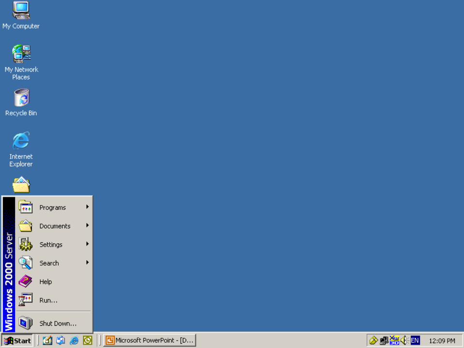
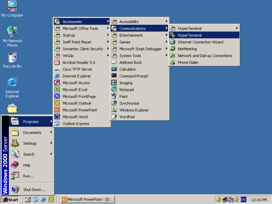
Emulation Software
WINDOWS
• Start Programs Accessories Communications HyperTerminal HyperTerminal.
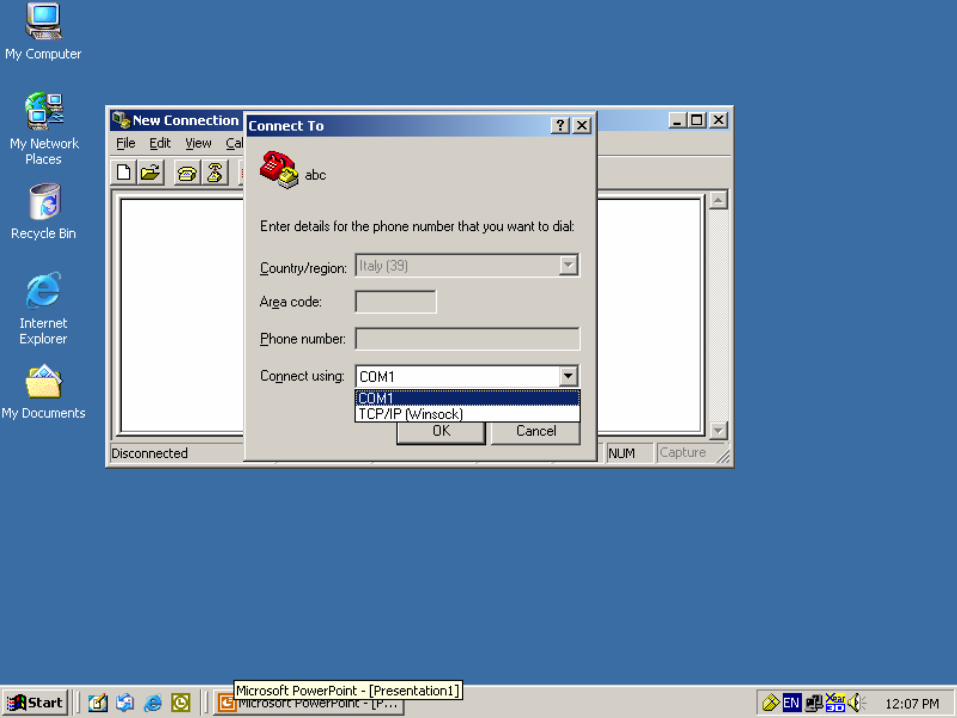
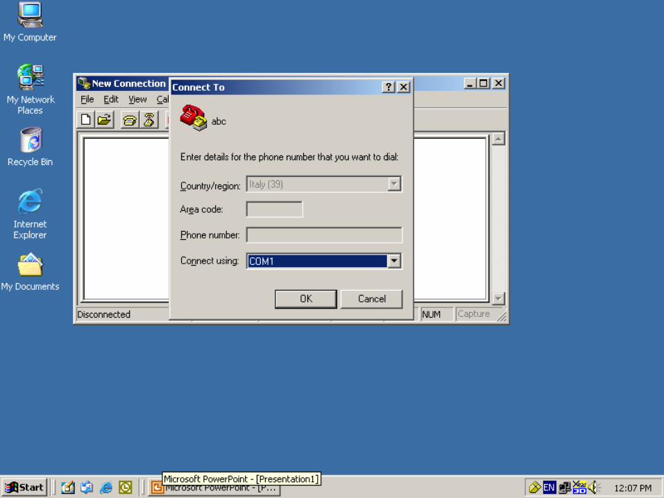
• Give the Connection Name & Select Any Icon
• Select Serial (Com) Port where Switch is Connected.
• In Port Settings Click on Restore Defaults
LINUX
• # minicom -s

4
Console Connectivity
E0
LAN - 192.168.1.0/24
Con 0

5
6

7

8

9
10

11

12
abc

13
14
15

16

17
18
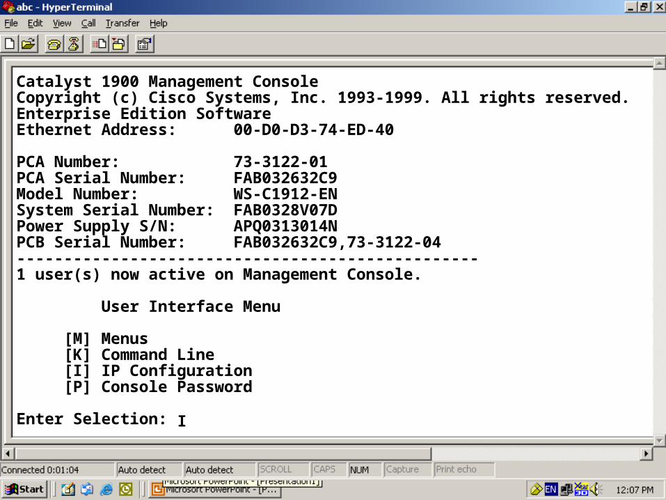
Catalyst 1900 Management ConsoleCopyright (c) Cisco Systems, Inc. 1993-1999. All rights reserved.Enterprise Edition SoftwareEthernet Address: 00-D0-D3-74-ED-40
PCA Number: 73-3122-01PCA Serial Number: FAB032632C9Model Number: WS-C1912-ENSystem Serial Number: FAB0328V07DPower Supply S/N: APQ0313014NPCB Serial Number: FAB032632C9,73-3122-04-------------------------------------------------1 user(s) now active on Management Console.
User Interface Menu
[M] Menus [K] Command Line [I] IP Configuration [P] Console Password
Enter Selection: I

19
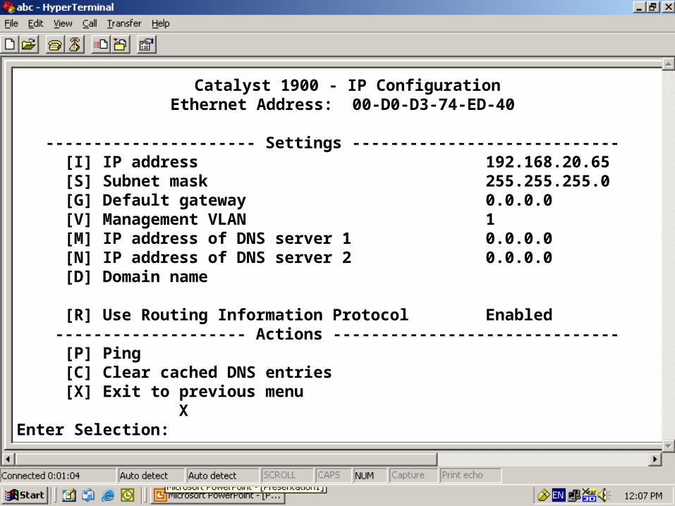
Catalyst 1900 - IP ConfigurationEthernet Address: 00-D0-D3-74-ED-40
---------------------- Settings ----------------------- [I] IP address 0.0.0.0 [S] Subnet mask 0.0.0.0 [G] Default gateway 0.0.0.0 [V] Management VLAN 1 [M] IP address of DNS server 1 0.0.0.0 [N] IP address of DNS server 2 0.0.0.0 [D] Domain name [R] Use Routing Information Protocol Enabled -------------------- Actions -------------------------- [P] Ping [C] Clear cached DNS entries [X] Exit to previous menu
Enter Selection: I

20
[D] Domain name [R] Use Routing Information Protocol Enabled -------------------- Actions -------------------------- [P] Ping [C] Clear cached DNS entries [X] Exit to previous menu
Enter Selection: I
This command assigns an administrative IP address to this switch. The new address will take effect immediately. If no IP address is assigned (or if the IP address is removed by setting it to 0.0.0.0), and the switch is connected to a DHCP server, the DHCP server may automatically assign an address to the switch.
Enter administrative IP address in dotted format (nnn.nnn.nnn.nnn)
Current setting ===> 0. 0. 0. 0
New setting ===>192.168.20.65

21
Catalyst 1900 - IP ConfigurationEthernet Address: 00-D0-D3-74-ED-40
---------------------- Settings ---------------------------- [I] IP address 192.168.20.65 [S] Subnet mask 0.0.0.0 [G] Default gateway 0.0.0.0 [V] Management VLAN 1 [M] IP address of DNS server 1 0.0.0.0 [N] IP address of DNS server 2 0.0.0.0 [D] Domain name [R] Use Routing Information Protocol Enabled -------------------- Actions ------------------------------ [P] Ping [C] Clear cached DNS entries [X] Exit to previous menu
Enter Selection: S

22
[M] IP address of DNS server 1 0.0.0.0 [N] IP address of DNS server 2 0.0.0.0 [D] Domain name [R] Use Routing Information Protocol Enabled -------------------- Actions -------------------------- [P] Ping [C] Clear cached DNS entries [X] Exit to previous menu
Enter Selection: I
This command defines the subnet mask for the IP address set by the[I] IP Address command.
Enter IP subnet mask in dotted quad format (nnn.nnn.nnn.nnn):
Current setting ===> 0. 0. 0. 0
New setting ===>255.255.255.0
23
Catalyst 1900 - IP ConfigurationEthernet Address: 00-D0-D3-74-ED-40
---------------------- Settings ---------------------------- [I] IP address 192.168.20.65 [S] Subnet mask 255.255.255.0 [G] Default gateway 0.0.0.0 [V] Management VLAN 1 [M] IP address of DNS server 1 0.0.0.0 [N] IP address of DNS server 2 0.0.0.0 [D] Domain name [R] Use Routing Information Protocol Enabled -------------------- Actions ------------------------------ [P] Ping [C] Clear cached DNS entries [X] Exit to previous menu
Enter Selection: X

24
Catalyst 1900 Management ConsoleCopyright (c) Cisco Systems, Inc. 1993-1999. All rights reserved.Enterprise Edition SoftwareEthernet Address: 00-D0-D3-74-ED-40
PCA Number: 73-3122-01PCA Serial Number: FAB032632C9Model Number: WS-C1912-ENSystem Serial Number: FAB0328V07DPower Supply S/N: APQ0313014NPCB Serial Number: FAB032632C9,73-3122-04-------------------------------------------------1 user(s) now active on Management Console.
User Interface Menu
[M] Menus [K] Command Line [I] IP Configuration [P] Console Password
Enter Selection: P
25
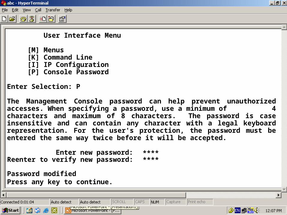
User Interface Menu
[M] Menus [K] Command Line [I] IP Configuration [P] Console Password
Enter Selection: P
The Management Console password can help prevent unauthorized accesses. When specifying a password, use a minimum of 4 characters and maximum of 8 characters. The password is case insensitive and can contain any character with a legal keyboard representation. For the user's protection, the password must be entered the same way twice before it will be accepted.
Enter new password: ********Reenter to verify new password:
Password modifiedPress any key to continue.

26
Catalyst 1900 Management ConsoleCopyright (c) Cisco Systems, Inc. 1993-1999. All rights reserved.Enterprise Edition SoftwareEthernet Address: 00-D0-D3-74-ED-40
PCA Number: 73-3122-01PCA Serial Number: FAB032632C9Model Number: WS-C1912-ENSystem Serial Number: FAB0328V07DPower Supply S/N: APQ0313014NPCB Serial Number: FAB032632C9,73-3122-04-------------------------------------------------1 user(s) now active on Management Console.
User Interface Menu
[M] Menus [K] Command Line
Enter Selection: M****Enter password:

27
Catalyst 1900 - Main Menu
[C] Console Settings [S] System [N] Network Management [P] Port Configuration [A] Port Addressing [D] Port Statistics Detail [M] Monitoring [V] Virtual LAN [R] Multicast Registration [F] Firmware [I] RS-232 Interface [U] Usage Summaries [H] Help [K] Command Line
[X] Exit Management Console
Enter Selection: S

28
Catalyst 1900 - System ConfigurationSystem Revision: 5 Address Capacity: 1024
System UpTime: 0day(s) 00hour(s) 06minute(s) 58second(s) ---------------------- Settings ------------------------------- [N] Name of system Switch [C] Contact name [L] Location [S] Switching mode FragmentFree [U] Use of store-and-forward for multicast Disabled [A] Action upon address violation Suspend [G] Generate alert on address violation Enabled [I] Address aging time 300 second(s) [P] Network port None [H] Half duplex back pressure (10-mbps ports) Disabled [E] Enhanced congestion control (10-mbps ports) Disabled -------------------- Actions --------------------------------- [R] Reset system [F] Reset to factory defaults [V] Reset VTP to factory def. [T] Reset to enable Bridge Group -------------------- Related Menus ---------------------------- [B] Broadcast storm control [X] Exit to Main MenuEnter Selection:
S

29
[H] Half duplex back pressure (10-mbps ports) Disabled [E] Enhanced congestion control (10-mbps ports) Disabled -------------------- Actions -------------------------------- [R] Reset system [F] Reset to factory defaults [V] Reset VTP to factory def. [T] Reset to enable Bridge Group -------------------- Related Menus ---------------------------- [B] Broadcast storm control [X] Exit to Main Menu
Enter Selection:
FragmentFree switching mode reduces bridge delay by making the forwarding decision after 64 bytes have been received. In contrast, Store-and-Forward switching mode waits until the entire frame has been received before the forwarding decision is made. This command sets the switching mode.
Select Store-and-Forward[1], or FragmentFree[2]:
Current setting ===> FragmentFree
New setting ===> Store-and-Forward

30
Catalyst 1900 - System ConfigurationSystem Revision: 5 Address Capacity: 1024
System UpTime: 0day(s) 00hour(s) 06minute(s) 58second(s) ---------------------- Settings ------------------------------- [N] Name of system Switch [C] Contact name [L] Location [S] Switching mode Store & Forward [U] Use of store-and-forward for multicast Disabled [A] Action upon address violation Suspend [G] Generate alert on address violation Enabled [I] Address aging time 300 second(s) [P] Network port None [H] Half duplex back pressure (10-mbps ports) Disabled [E] Enhanced congestion control (10-mbps ports) Disabled -------------------- Actions --------------------------------- [R] Reset system [F] Reset to factory defaults [V] Reset VTP to factory def. [T] Reset to enable Bridge Group -------------------- Related Menus ---------------------------- [B] Broadcast storm control [X] Exit to Main MenuEnter Selection:
X

31
Catalyst 1900 - Main Menu
[C] Console Settings [S] System [N] Network Management [P] Port Configuration [A] Port Addressing [D] Port Statistics Detail [M] Monitoring [V] Virtual LAN [R] Multicast Registration [F] Firmware [I] RS-232 Interface [U] Usage Summaries [H] Help [K] Command Line
[X] Exit Management Console
Enter Selection: X

32
[N] Network Management [P] Port Configuration [A] Port Addressing [D] Port Statistics Detail [M] Monitoring [V] Virtual LAN [R] Multicast Registration [F] Firmware [I] RS-232 Interface [U] Usage Summaries [H] Help [K] Command Line
[X] Exit Management Console
Enter Selection: X
This command will exit and log you out of the Management Console.
Exit Management Console, [Y]es or [N]o? Yes

33
Catalyst 1900 Management ConsoleCopyright (c) Cisco Systems, Inc. 1993-1999. All rights reserved.Enterprise Edition SoftwareEthernet Address: 00-D0-D3-74-ED-40
PCA Number: 73-3122-01PCA Serial Number: FAB032632C9Model Number: WS-C1912-ENSystem Serial Number: FAB0328V07DPower Supply S/N: APQ0313014NPCB Serial Number: FAB032632C9,73-3122-04-------------------------------------------------1 user(s) now active on Management Console.
User Interface Menu
[M] Menus [K] Command Line
Enter Selection: K

34
CLI session with the switch is open. To end the CLI session, enter [Exit].
>enable#show running-config
User Mode: Commands : ping, enable
User Mode: Commands : ping, enablePrivileged Mode: Commands :
show, copy, configure terminal, reload,
Privileged Mode: Commands :
show, copy, configure terminal, reload,
Building configuration...Current configuration:!!!ip address 192.168.20.65 255.255.255.0!!!!enable password level 15 "ZOOM"!!--More--
35
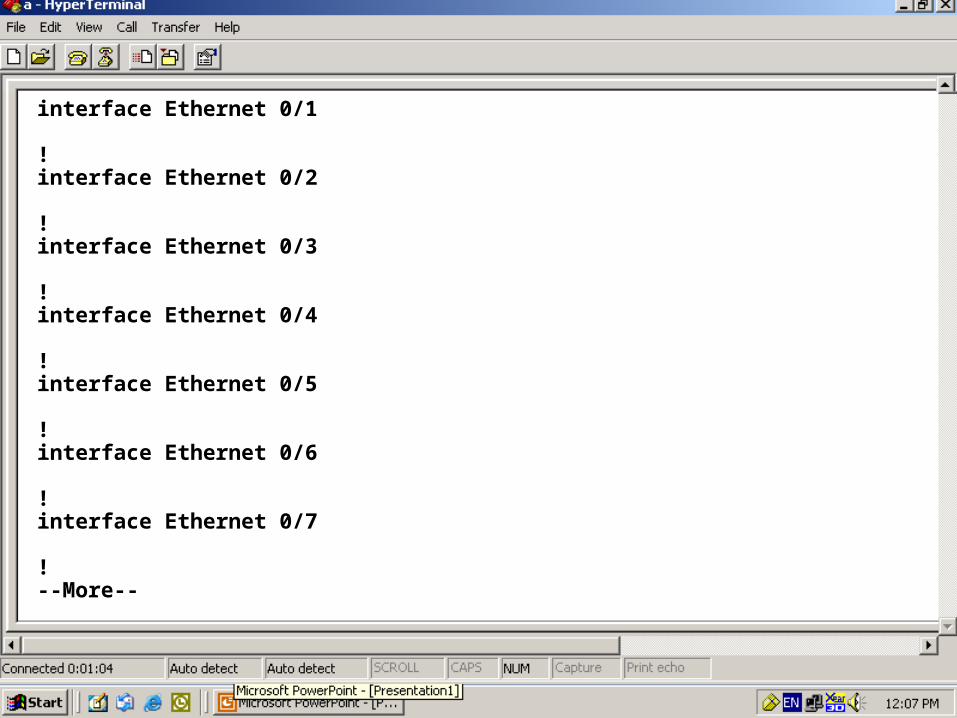
interface Ethernet 0/1
!interface Ethernet 0/2
!interface Ethernet 0/3
!interface Ethernet 0/4
!interface Ethernet 0/5
!interface Ethernet 0/6
!interface Ethernet 0/7
!--More--
36
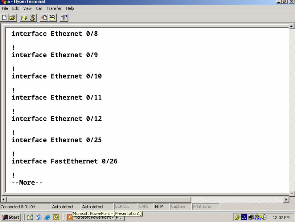
interface Ethernet 0/8
!interface Ethernet 0/9
!interface Ethernet 0/10
!interface Ethernet 0/11
!interface Ethernet 0/12
!interface Ethernet 0/25
!interface FastEthernet 0/26
!--More--
37
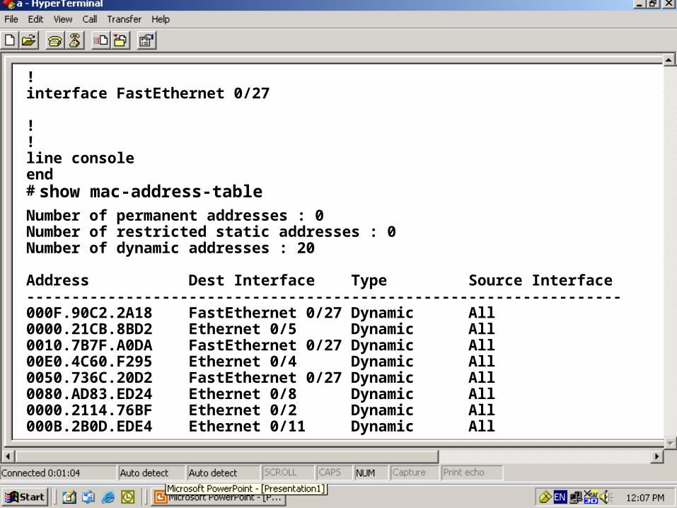
!interface FastEthernet 0/27
!!line consoleend# show mac-address-tableNumber of permanent addresses : 0Number of restricted static addresses : 0Number of dynamic addresses : 20
Address Dest Interface Type Source Interface------------------------------------------------------------------000F.90C2.2A18 FastEthernet 0/27 Dynamic All0000.21CB.8BD2 Ethernet 0/5 Dynamic All0010.7B7F.A0DA FastEthernet 0/27 Dynamic All00E0.4C60.F295 Ethernet 0/4 Dynamic All0050.736C.20D2 FastEthernet 0/27 Dynamic All0080.AD83.ED24 Ethernet 0/8 Dynamic All0000.2114.76BF Ethernet 0/2 Dynamic All000B.2B0D.EDE4 Ethernet 0/11 Dynamic All

38
# configure terminalEnter configuration commands, one per line. End with CNTL/Z.(config)# hostname Switch1900
Global Configuration Mode: Commands :
hostname, ip address, enable secret
Global Configuration Mode: Commands :
hostname, ip address, enable secretSwitch1900(config)# ip address 192.168.20.65 255.255.255.0Switch1900(config)# enable secret zoomSwitch1900(config)# ^ZSwitch1900#

39
Visual Switch Manager Access
E0
LAN - 192.168.1.0/24
Con 0

40

41
http://192.168.20.65
****

42

43

44

45

46

47

48
• A Layer 2 Security
• Divides a Single Broadcast domain into Multiple
Broadcast domains.
• By default all ports of the switch are in VLAN1 . This
VLAN1 is known as Administrative VLAN or
Management VLAN
• VLAN can be created from 2 – 1001
• Can be Configured on a Manageable switch only
• 2 Types of VLAN Membership
– Static VLAN
– Dynamic VLAN
Virtual LAN

49
Static VLAN
• Static VLAN’s are based on port numbers
• Need to manually assign a port on a switch to a
VLAN
• Also called Port-Based VLANs
• It can be a member of single VLAN and not
multiple VLAN’s

50
• Dynamic VLAN’s are based on the MAC address of
a PC
• Switch automatically assigns the port to a VLAN
• Each port can be a member of multiple VLAN’s
• For Dynamic VLAN configuration, a software called
VMPS( VLAN Membership Policy Server) is needed
Dynamic VLAN

51
• The PC port from which you Telnet to the switch
must be in a Default VLAN
• If all the ports are in different VLAN’s ,can you
Telnet to the switch?
Answer : NO
• So to remove the VLAN’s enter through console
port
Important Notes

52
VLAN - Lab Diagram
192.168.20.6 192.168.20.5 192.168.20.4
192.168.20.7 192.168.20.8 192.168.20.9
192.168.20.1 192.168.20.2 192.168.20.3
SWITCH
Default VLANi.e. VLAN No. 1

53
SalesVlan no. 5
SalesVlan no. 5
VLAN - Lab Diagram
192.168.20.1 192.168.20.2 192.168.20.3
SWITCH

54
SalesVlan no. 5
SalesVlan no. 5
VLAN - Configuration
192.168.20.1 192.168.20.2 192.168.20.3
SWITCH

55
SalesVlan no. 5
SalesVlan no. 5
VLAN - Lab Diagram
192.168.20.1 192.168.20.2 192.168.20.3
SWITCH

56
Trunking Configuration
MarketingVlan no. 6
SalesVlan no. 5
192.168.20.1 192.168.20.2 192.168.20.3
SWITCH
MarketingVlan no. 6
SalesVlan no. 5
192.168.20.6 192.168.20.5 192.168.20.4
SWITCH
Fa0/27
Fa0/26

57
• VTP is a CISCO proprietary protocol
• used to share the VLAN configurations with multiple
switches.
• Switches are connected using Fast Ethernet ports
Virtual LAN Trunking Protocol
58
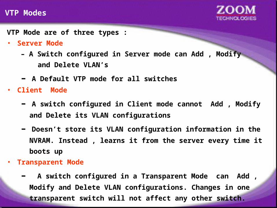
VTP Mode are of three types :
• Server Mode
– A Switch configured in Server mode can Add , Modify
and Delete VLAN’s
– A Default VTP mode for all switches
• Client Mode
– A switch configured in Client mode cannot Add , Modify and
Delete its VLAN configurations
– Doesn’t store its VLAN configuration information in the
NVRAM. Instead , learns it from the server every time it
boots up
• Transparent Mode
– A switch configured in a Transparent Mode can Add ,
Modify and Delete VLAN configurations. Changes in one
transparent switch will not affect any other switch.
VTP Modes
59
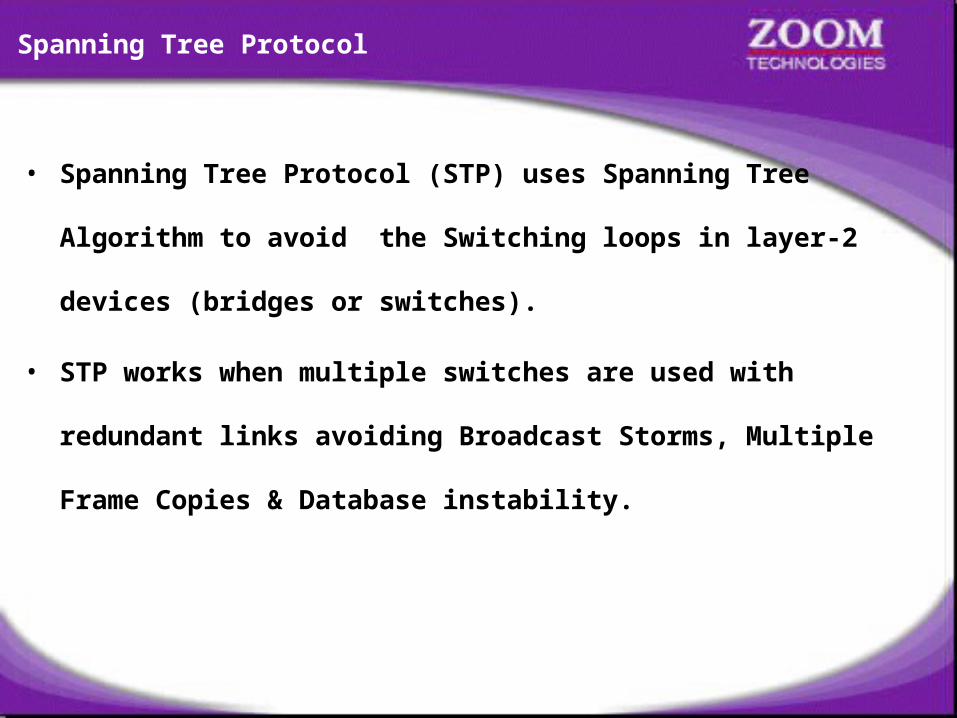
• Spanning Tree Protocol (STP) uses Spanning Tree
Algorithm to avoid the Switching loops in layer-2
devices (bridges or switches).
• STP works when multiple switches are used with
redundant links avoiding Broadcast Storms, Multiple
Frame Copies & Database instability.
Spanning Tree Protocol
60
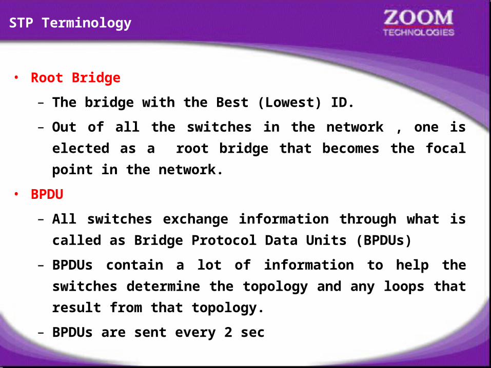
• Root Bridge
– The bridge with the Best (Lowest) ID.
– Out of all the switches in the network , one is elected
as a root bridge that becomes the focal point in the
network.
• BPDU
– All switches exchange information through what is
called as Bridge Protocol Data Units (BPDUs)
– BPDUs contain a lot of information to help the
switches determine the topology and any loops that
result from that topology.
– BPDUs are sent every 2 sec
STP Terminology

61
• Bridge ID
– Each switch has a unique identifier called a
Bridge ID or Switch ID
– Bridge ID = Priority + MAC address of the switch
– When a switch advertises a BPDU , they place their
switch id in these BPDUs.
• Non-Root bridge
– All Switches other than the Root Bridge are Non-Root
Bridges
• Root port
– The link directly connected to the root bridge, or the
shortest path to the root bridge is a root port. The port
with the least cost to the root bridge
STP Terminology
62
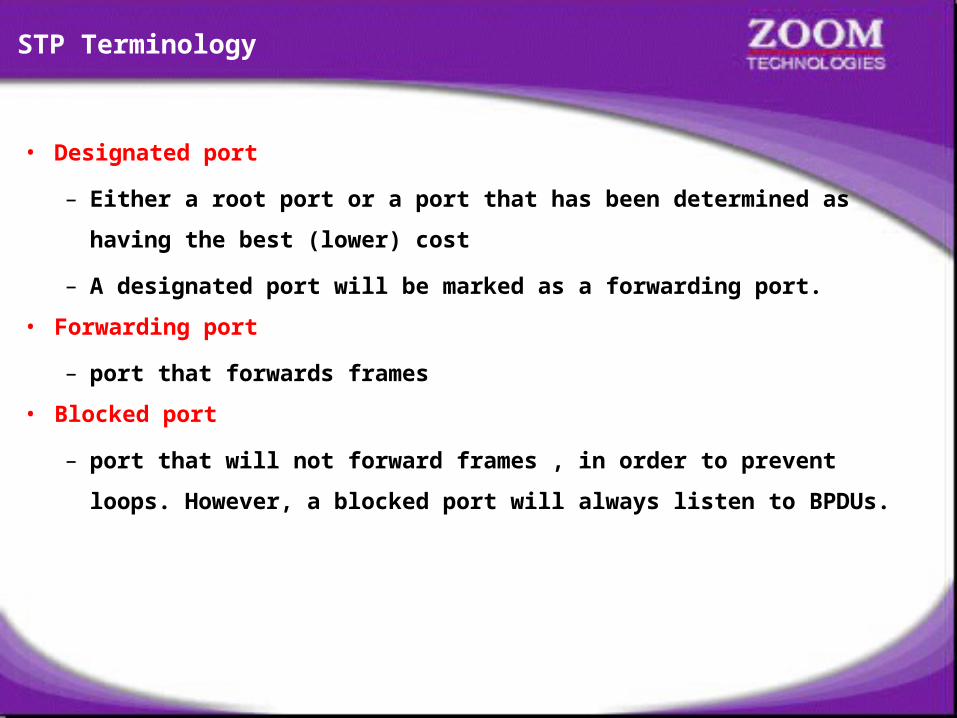
• Designated port
– Either a root port or a port that has been determined as
having the best (lower) cost
– A designated port will be marked as a forwarding port.
• Forwarding port
– port that forwards frames
• Blocked port
– port that will not forward frames , in order to prevent
loops. However, a blocked port will always listen to BPDUs.
STP Terminology

63
• Blocking
• Listening
• Learning
• Forwarding
STP - Port States

64

65
Microsoft Windows 2000 [Version 5.00.2195](C) Copyright 1985-2000 Microsoft Corp.C:\>pinging 192.168.20.2 with 32 bytes of data:
ping 192.168.20.2
Ping statistics for 192.168.20.2: Packets: Sent = 4, Received = 4, Lost = 0 (0% loss),Approximate round trip times in milli-seconds: Minimum = 0ms, Maximum = 0ms, Average = 0ms
C:\>
Reply from 192.168.20.2: bytes=32 time<10ms TTL=255Reply from 192.168.20.2: bytes=32 time<10ms TTL=255Reply from 192.168.20.2: bytes=32 time<10ms TTL=255Reply from 192.168.20.2: bytes=32 time<10ms TTL=255
pinging 192.168.20.3 with 32 bytes of data:ping 192.168.20.3
Ping statistics for 192.168.20.3: Packets: Sent = 4, Received = 4, Lost = 0 (0% loss),Approximate round trip times in milli-seconds: Minimum = 0ms, Maximum = 0ms, Average = 0msC:\>
Reply from 192.168.20.3: bytes=32 time<10ms TTL=255Reply from 192.168.20.3: bytes=32 time<10ms TTL=255Reply from 192.168.20.3: bytes=32 time<10ms TTL=255Reply from 192.168.20.3: bytes=32 time<10ms TTL=255

66
Microsoft Windows 2000 [Version 5.00.2195](C) Copyright 1985-2000 Microsoft Corp.C:\>pinging 192.168.20.1 with 32 bytes of data:
ping 192.168.20.1
Ping statistics for 192.168.20.1: Packets: Sent = 4, Received = 4, Lost = 0 (0% loss),Approximate round trip times in milli-seconds: Minimum = 0ms, Maximum = 0ms, Average = 0ms
C:\>
Reply from 192.168.20.1: bytes=32 time<10ms TTL=255Reply from 192.168.20.1: bytes=32 time<10ms TTL=255Reply from 192.168.20.1: bytes=32 time<10ms TTL=255Reply from 192.168.20.1: bytes=32 time<10ms TTL=255
pinging 192.168.20.3 with 32 bytes of data:ping 192.168.20.3
Ping statistics for 192.168.20.3: Packets: Sent = 4, Received = 4, Lost = 0 (0% loss),Approximate round trip times in milli-seconds: Minimum = 0ms, Maximum = 0ms, Average = 0msC:\>
Reply from 192.168.20.3: bytes=32 time<10ms TTL=255Reply from 192.168.20.3: bytes=32 time<10ms TTL=255Reply from 192.168.20.3: bytes=32 time<10ms TTL=255Reply from 192.168.20.3: bytes=32 time<10ms TTL=255

67
Microsoft Windows 2000 [Version 5.00.2195](C) Copyright 1985-2000 Microsoft Corp.C:\>pinging 192.168.20.1 with 32 bytes of data:
ping 192.168.20.1
Ping statistics for 192.168.20.1: Packets: Sent = 4, Received = 4, Lost = 0 (0% loss),Approximate round trip times in milli-seconds: Minimum = 0ms, Maximum = 0ms, Average = 0ms
C:\>
Reply from 192.168.20.1: bytes=32 time<10ms TTL=255Reply from 192.168.20.1: bytes=32 time<10ms TTL=255Reply from 192.168.20.1: bytes=32 time<10ms TTL=255Reply from 192.168.20.1: bytes=32 time<10ms TTL=255
pinging 192.168.20.2 with 32 bytes of data:ping 192.168.20.2
Ping statistics for 192.168.20.2: Packets: Sent = 4, Received = 4, Lost = 0 (0% loss),Approximate round trip times in milli-seconds: Minimum = 0ms, Maximum = 0ms, Average = 0msC:\>
Reply from 192.168.20.2: bytes=32 time<10ms TTL=255Reply from 192.168.20.2: bytes=32 time<10ms TTL=255Reply from 192.168.20.2: bytes=32 time<10ms TTL=255Reply from 192.168.20.2: bytes=32 time<10ms TTL=255

68
Microsoft Windows 2000 [Version 5.00.2195](C) Copyright 1985-2000 Microsoft Corp.C:\>Connecting .....
telnet 192.168.20.65

69
Catalyst 1900 Management ConsoleCopyright (c) Cisco Systems, Inc. 1993-1999. All rights reserved.Enterprise Edition SoftwareEthernet Address: 00-D0-D3-74-ED-40
PCA Number: 73-3122-01PCA Serial Number: FAB032632C9Model Number: WS-C1912-ENSystem Serial Number: FAB0328V07DPower Supply S/N: APQ0313014NPCB Serial Number: FAB032632C9,73-3122-04-------------------------------------------------1 user(s) now active on Management Console.
User Interface Menu
[M] Menus [K] Command Line
Enter Selection: K
****Enter password:

70
CLI session with the switch is open. To end the CLI session, enter [Exit].
Switch1900>enableSwitch1900#show vlan
VLAN Name Status Ports-------------------------------------------------1 default Enabled 1-12, AUI, A, B1002 fddi-default Suspended1003 token-ring-defau Suspended1004 fddinet-default Suspended1005 trnet-default Suspended-------------------------------------------------
VLAN Type SAID MTU Parent RingNo BriNo Stp Trans1 Trans2-------------------------------------------------------------------------1 Ethernet 100001 1500 0 0 0 Unkn 1002 10031002 FDDI 101002 1500 0 0 0 Unkn 1 10031003 Token-Ring 101003 1500 1005 1 0 Unkn 1 10021004 FDDI-Net 101004 1500 0 0 1 IEEE 0 01005 Token-Ring-Net 101005 1500 0 0 1 IEEE 0 0-------------------------------------------------------------------------Switch1900#

71
Switch1900#configure terminalEnter configuration commands, one per line. End with CNTL/ZSwitch1900(config)# vlan 5 name sales
VLAN Name Status Ports-------------------------------------------------1 default Enabled 1-12, AUI, A, B5 sales Enabled1002 fddi-default Suspended1003 token-ring-defau Suspended1004 fddinet-default Suspended1005 trnet-default Suspended-------------------------------------------------VLAN Type SAID MTU Parent RingNo BriNo Stp Trans1 Trans2-------------------------------------------------------------------------1 Ethernet 100001 1500 0 0 0 Unkn 1002 10031002 FDDI 101002 1500 0 0 0 Unkn 1 10031003 Token-Ring 101003 1500 1005 1 0 Unkn 1 10021004 FDDI-Net 101004 1500 0 0 1 IEEE 0 01005 Token-Ring-Net 101005 1500 0 0 1 IEEE 0 0-------------------------------------------------------------------------Switch1900#
Switch1900#show vlanSwitch1900(config)# ^Z
Creating VLAN - 1900 SeriesSwitch(config)# vlan <vlan no.> name <name>
Creating VLAN - 2900 SeriesSwitch# vlan databaseSwitch(vlan)# vlan <vlan no.> name <name>
Creating VLAN - 1900 SeriesSwitch(config)# vlan <vlan no.> name <name>
Creating VLAN - 2900 SeriesSwitch# vlan databaseSwitch(vlan)# vlan <vlan no.> name <name>

72
Switch1900#configure terminalEnter configuration commands, one per line. End with CNTL/ZSwitch1900(config)# interface ethernet 0/1
Switch1900(config-if)#Switch1900(config-if)# vlan-membership static 5
exitSwitch1900(config)# interface ethernet 0/3
Switch1900(config-if)#Switch1900(config-if)# vlan-membership static 5
^ZSwitch1900#VLAN Name Status Ports-------------------------------------------------1 default Enabled 2,4-12, AUI, A, B5 sales Enabled 1,31002 fddi-default Suspended1003 token-ring-defau Suspended1004 fddinet-default Suspended1005 trnet-default Suspended-------------------------------------------------VLAN Type SAID MTU Parent RingNo BriNo Stp Trans1 Trans2-------------------------------------------------------------------------1 Ethernet 100001 1500 0 0 0 Unkn 1002 10031002 FDDI 101002 1500 0 0 0 Unkn 1 1003-------------------------------------------------------------------------Switch1900#
show vlan
VLAN Membership – 1900 SeriesSwitch(config)# interface <interface type> <interface no>Switch(config-if)# vlan-membership static <vlan no.>
VLAN Membership – 2900 SeriesSwitch(config)# interface <interface type> <interface no>Switch(config-if)# switchport access vlan <vlan no.>
VLAN Membership – 1900 SeriesSwitch(config)# interface <interface type> <interface no>Switch(config-if)# vlan-membership static <vlan no.>
VLAN Membership – 2900 SeriesSwitch(config)# interface <interface type> <interface no>Switch(config-if)# switchport access vlan <vlan no.>
73
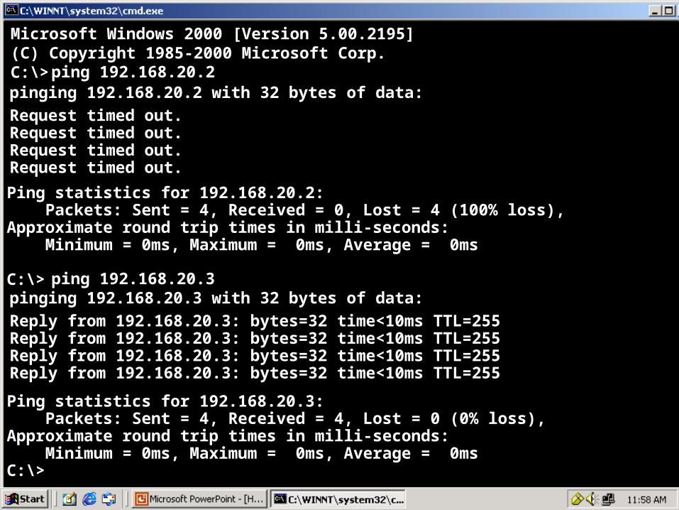
Microsoft Windows 2000 [Version 5.00.2195](C) Copyright 1985-2000 Microsoft Corp.C:\>pinging 192.168.20.2 with 32 bytes of data:
ping 192.168.20.2
Ping statistics for 192.168.20.2: Packets: Sent = 4, Received = 0, Lost = 4 (100% loss),Approximate round trip times in milli-seconds: Minimum = 0ms, Maximum = 0ms, Average = 0ms
C:\>
Request timed out.Request timed out.Request timed out.Request timed out.
pinging 192.168.20.3 with 32 bytes of data:ping 192.168.20.3
Ping statistics for 192.168.20.3: Packets: Sent = 4, Received = 4, Lost = 0 (0% loss),Approximate round trip times in milli-seconds: Minimum = 0ms, Maximum = 0ms, Average = 0msC:\>
Reply from 192.168.20.3: bytes=32 time<10ms TTL=255Reply from 192.168.20.3: bytes=32 time<10ms TTL=255Reply from 192.168.20.3: bytes=32 time<10ms TTL=255Reply from 192.168.20.3: bytes=32 time<10ms TTL=255

74
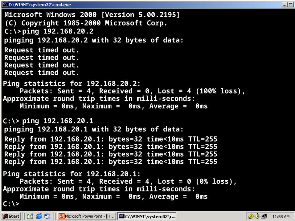
Microsoft Windows 2000 [Version 5.00.2195](C) Copyright 1985-2000 Microsoft Corp.C:\>pinging 192.168.20.1 with 32 bytes of data:
ping 192.168.20.1
Ping statistics for 192.168.20.1: Packets: Sent = 4, Received = 0, Lost = 4 (100% loss),Approximate round trip times in milli-seconds: Minimum = 0ms, Maximum = 0ms, Average = 0ms
C:\>
Request timed out.Request timed out.Request timed out.Request timed out.
pinging 192.168.20.3 with 32 bytes of data:ping 192.168.20.3
Ping statistics for 192.168.20.3: Packets: Sent = 4, Received = 0, Lost = 4 (100% loss),Approximate round trip times in milli-seconds: Minimum = 0ms, Maximum = 0ms, Average = 0msC:\>
Request timed out.Request timed out.Request timed out.Request timed out.
75
Microsoft Windows 2000 [Version 5.00.2195](C) Copyright 1985-2000 Microsoft Corp.C:\>pinging 192.168.20.2 with 32 bytes of data:
ping 192.168.20.2
Ping statistics for 192.168.20.2: Packets: Sent = 4, Received = 0, Lost = 4 (100% loss),Approximate round trip times in milli-seconds: Minimum = 0ms, Maximum = 0ms, Average = 0ms
C:\>
Request timed out.Request timed out.Request timed out.Request timed out.
pinging 192.168.20.1 with 32 bytes of data:ping 192.168.20.1
Ping statistics for 192.168.20.1: Packets: Sent = 4, Received = 4, Lost = 0 (0% loss),Approximate round trip times in milli-seconds: Minimum = 0ms, Maximum = 0ms, Average = 0msC:\>
Reply from 192.168.20.1: bytes=32 time<10ms TTL=255Reply from 192.168.20.1: bytes=32 time<10ms TTL=255Reply from 192.168.20.1: bytes=32 time<10ms TTL=255Reply from 192.168.20.1: bytes=32 time<10ms TTL=255
76
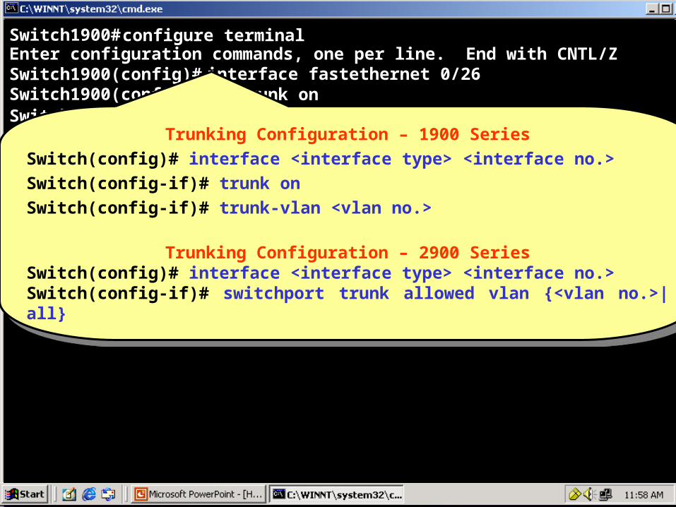
Switch1900#configure terminalEnter configuration commands, one per line. End with CNTL/ZSwitch1900(config)# interface fastethernet 0/26
Switch1900(config-if)#Switch1900(config-if)# trunk on
trunk-vlan 5Switch1900(config-if)# trunk-vlan 6Switch1900(config-if)#Trunking Configuration – 1900 Series
Switch(config)# interface <interface type> <interface no.>Switch(config-if)# trunk onSwitch(config-if)# trunk-vlan <vlan no.>
Trunking Configuration – 2900 SeriesSwitch(config)# interface <interface type> <interface no.>Switch(config-if)# switchport trunk allowed vlan {<vlan no.>|all}
Trunking Configuration – 1900 SeriesSwitch(config)# interface <interface type> <interface no.>Switch(config-if)# trunk onSwitch(config-if)# trunk-vlan <vlan no.>
Trunking Configuration – 2900 SeriesSwitch(config)# interface <interface type> <interface no.>Switch(config-if)# switchport trunk allowed vlan {<vlan no.>|all}

77
Switch1900#configure terminalEnter configuration commands, one per line. End with CNTL/ZSwitch1900(config)# interface fastethernet 0/27
Switch1900(config-if)#Switch1900(config-if)# trunk on
trunk-vlan 5Switch1900(config-if)# trunk-vlan 6Switch1900(config-if)#Trunking Configuration – 1900 Series
Switch(config)# interface <interface type> <interface no.>Switch(config-if)# trunk onSwitch(config-if)# trunk-vlan <vlan no.>
Trunking Configuration – 2900 SeriesSwitch(config)# interface <interface type> <interface no.>Switch(config-if)# switchport trunk allowed vlan {<vlan no.>|all}
Trunking Configuration – 1900 SeriesSwitch(config)# interface <interface type> <interface no.>Switch(config-if)# trunk onSwitch(config-if)# trunk-vlan <vlan no.>
Trunking Configuration – 2900 SeriesSwitch(config)# interface <interface type> <interface no.>Switch(config-if)# switchport trunk allowed vlan {<vlan no.>|all}