Switching - EECS Instructional Support Group Home …inst.eecs.berkeley.edu/~ee122/sp07/switching...
39
Unit 18 Switching Acknowledgments: These slides were originally developed by Prof. Jean Walrand for EE122. The past and current EE122 instructors including Profs. Kevin Fall, Abhay Parekh, Shyam Parekh, and Adam Wolisz have contributed to their evolution.
Transcript of Switching - EECS Instructional Support Group Home …inst.eecs.berkeley.edu/~ee122/sp07/switching...

Unit 18
Switching
Acknowledgments: These slides were originally developed by Prof. Jean Walrand for EE122.The past and current EE122 instructors including Profs. Kevin Fall, Abhay Parekh, Shyam Parekh,
and Adam Wolisz have contributed to their evolution.
TOC: Switching & Forwarding� Why?
� Switching Techniques
� Switch Characteristics
� Switch Examples
� Switch Architectures
� Summary
TOC – Switching
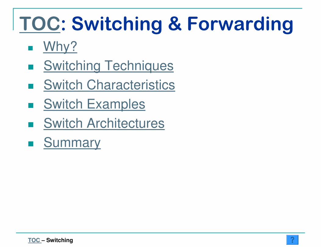
� Direct vs. Switched Networks:
� Direct Network Limitations:
� Shared medium
— Distance (coordination delay; propagation limitation)
— Number of hosts (collisions; shared bandwidth; address tables)
— Single link technology (cannot mix optical, wireless, …)
� Point-to-point links
— O(n2) links
� Internetworking: Externality gain at low cost
Why?
Single
link
n links
SwitchesDirect Switched
TOC – Switching – Why?

� Circuit-Switching (e.g., Telephone net.)
� Packet-Switching� Datagram (e.g., IP, Ethernet)
� Virtual Circuits (e.g., MPLS, ATM)
� Source Routing
� Comparison
Techniques
TOC – Switching – Techniques
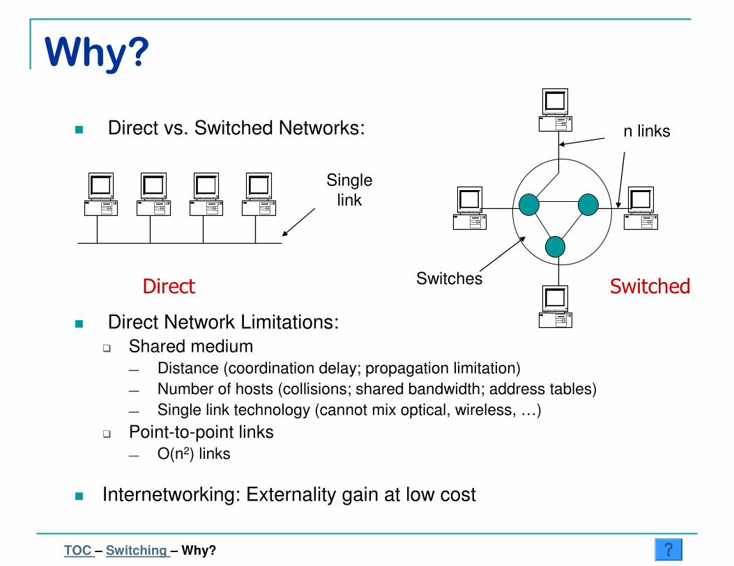
� Mechanism:
Circuit-Switching Link divided into fixed,independent circuits
Circuit SwitchConnection list
Time scale: connection
(e.g., TDM, WDM)
• Packets not switched independently (establish circuit before sending data)
• Dedicated path and resources from source to destination• Setup time; low delays and guaranteed resources thereafter
� Features:
TOC – Switching – Techniques – Circuit
(Typical Implementation: Time-Space-Time Switch)

� Mechanism:
Packet-SwitchingWhole link shared by
all packets
Packet Switch
• Data separated into packets• Switching decision (output port) for each individual packet• Statistical multiplexing: Sum of peak rates may exceedlink bandwidth (as long as mean does not)
� Features:
TOC – Switching – Techniques – Packet
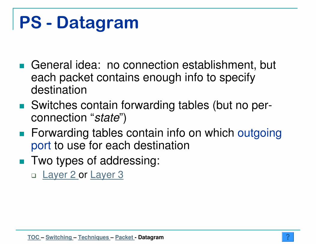
PS - Datagram
� General idea: no connection establishment, but each packet contains enough info to specify destination
� Switches contain forwarding tables (but no per-connection “state”)
� Forwarding tables contain info on which outgoing port to use for each destination
� Two types of addressing:� Layer 2 or Layer 3
TOC – Switching – Techniques – Packet - Datagram
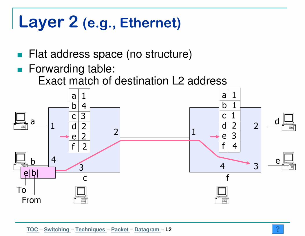
Layer 2 (e.g., Ethernet)
� Flat address space (no structure)
� Forwarding table:Exact match of destination L2 address
a
b
c
d
e
f
12
34
12
34
a 1b 4c 3d 2e 2f 2
a 1b 1c 1d 2e 3f 4
e|b|
ToFrom
TOC – Switching – Techniques – Packet – Datagram – L2
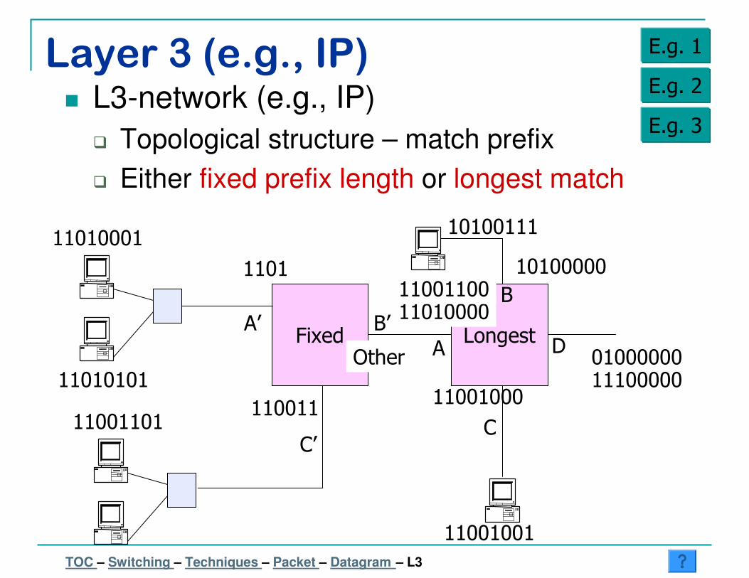
Layer 3 (e.g., IP)� L3-network (e.g., IP)
� Topological structure – match prefix
� Either fixed prefix length or longest match
E.g. 1
E.g. 2
E.g. 3
TOC – Switching – Techniques – Packet – Datagram – L3
Fixed
11010001
11001101
Longest
11001001
10100111
11010000
11001000
10100000
01000000
1101
Other A
B
C
DA’
C’
B’
11010101
110011
11100000
11001100

Layer 3 (e.g., IP) E.g. 1
11011001 matches 4 bits at A, 1 at B, 3 at C � A = LPM4 bits at A’ � A’ = EM
TOC – Switching – Techniques – Packet – Datagram – L3
Fixed
11010001
11001101
Longest
11001001
10100111
11010000
11001000
10100000
01000000
1101
Other A
B
C
DA’
C’
B’
11010101
110011
11100000
11011001
11001100
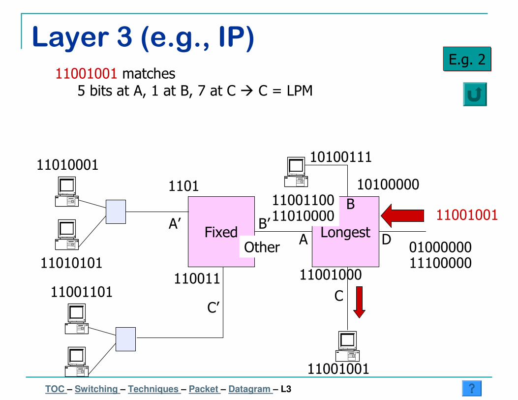
Layer 3 (e.g., IP)E.g. 2
11001001 matches 5 bits at A, 1 at B, 7 at C � C = LPM
TOC – Switching – Techniques – Packet – Datagram – L3
11001001Fixed
11010001
11001101
Longest
11001001
10100111
11010000
11001000
10100000
01000000
1101
OtherA
B
C
DA’
C’
B’
11010101110011
11100000
11001100
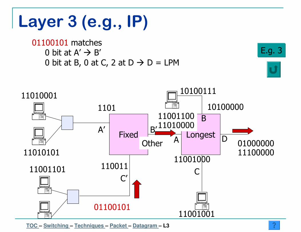
Layer 3 (e.g., IP)
E.g. 301100101 matches
0 bit at A’ � B’0 bit at B, 0 at C, 2 at D � D = LPM
TOC – Switching – Techniques – Packet – Datagram – L3
Fixed
11010001
11001101
Longest
11001001
10100111
11010000
11001000
10100000
01000000
1101
Other A
B
C
DA’
C’
B’
11010101
110011
11100000
01100101
11001100
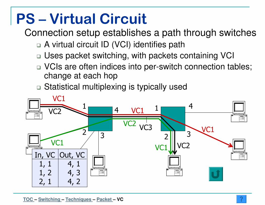
PS – Virtual CircuitConnection setup establishes a path through switches
� A virtual circuit ID (VCI) identifies path
� Uses packet switching, with packets containing VCI
� VCIs are often indices into per-switch connection tables; change at each hop
� Statistical multiplexing is typically used
1
2 3
4 1
2 3
4VC1
VC1
VC1
VC1
VC2
VC1
VC2
VC3
VC2
In, VC Out, VC1, 1 4, 11, 2 4, 32, 1 4, 2
….
TOC – Switching – Techniques – Packet – VC
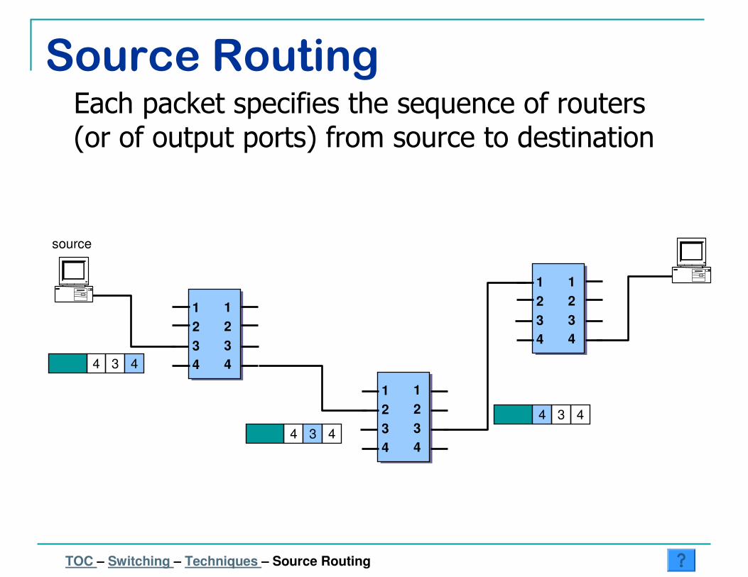
Source Routing
1
2
3
4
1
2
3
4
1
2
3
4
1
2
3
4
1
2
3
4
1
2
3
4
4
source
3 4
4 3 4
4 3 4
Each packet specifies the sequence of routers (or of output ports) from source to destination
TOC – Switching – Techniques – Source Routing
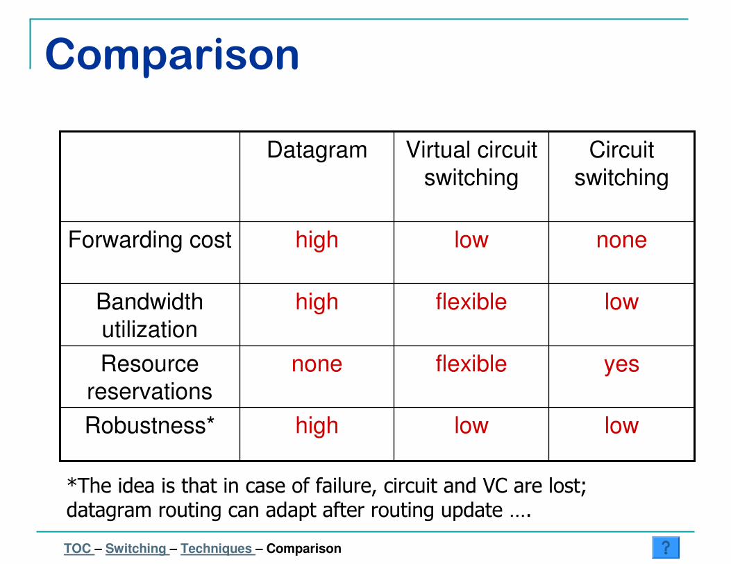
Comparison
lowlowhighRobustness*
yesflexiblenoneResource
reservations
lowflexiblehighBandwidth
utilization
nonelowhighForwarding cost
Circuit
switching
Virtual circuit
switching
Datagram
*The idea is that in case of failure, circuit and VC are lost; datagram routing can adapt after routing update ….
TOC – Switching – Techniques – Comparison

Characteristics of Switch/Router
� Ports
� Fast Ethernet, OC-3, ATM, …
� Protocols
� ST, Link Agg., VLAN, OSPF, RIP, BGP, VPN, Load Balancing, WRED, WFQ
� Performance
� Throughput, Reliability, Power, …
TOC – Switching – Characteristics
Examples
� Juniper M160
� Cisco “GSR”
� Cisco “7600”
� Cisco “catalyst 6500”
� Extreme “Summit”
� Foundry “ServerIron”
TOC – Switching – Examples

Cisco GSR - 12416
� WAN Router – Large throughput; SONET links
� Up to 16 line cards at 10 Gbps each
� Crossbar Fabric
� Line Cards:
1-port OC-192c
4-port OC48c
Many others
(ATM, Ethernet, …)
Cisco GSR 12416
6ft
19”
2ft
TOC – Switching – Examples – GSR
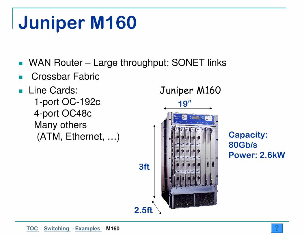
Juniper M160
� WAN Router – Large throughput; SONET links
� Crossbar Fabric
� Line Cards:
1-port OC-192c
4-port OC48c
Many others
(ATM, Ethernet, …)
Juniper M160
3ft
2.5ft
19”
Capacity:
80Gb/s
Power: 2.6kW
TOC – Switching – Examples – M160
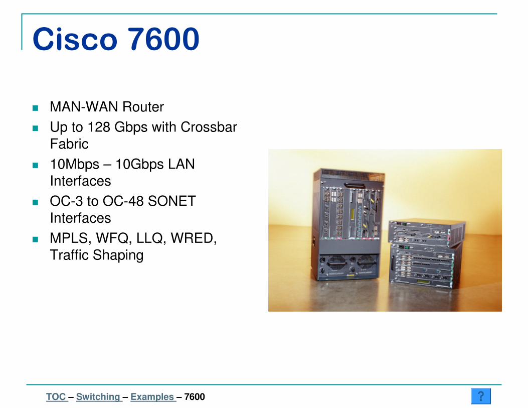
Cisco 7600
� MAN-WAN Router
� Up to 128 Gbps with Crossbar
Fabric
� 10Mbps – 10Gbps LAN
Interfaces
� OC-3 to OC-48 SONET
Interfaces
� MPLS, WFQ, LLQ, WRED,
Traffic Shaping
TOC – Switching – Examples – 7600
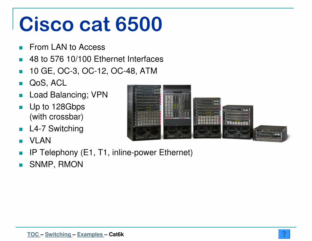
Cisco cat 6500� From LAN to Access
� 48 to 576 10/100 Ethernet Interfaces
� 10 GE, OC-3, OC-12, OC-48, ATM
� QoS, ACL
� Load Balancing; VPN
� Up to 128Gbps
(with crossbar)
� L4-7 Switching
� VLAN
� IP Telephony (E1, T1, inline-power Ethernet)
� SNMP, RMON
TOC – Switching – Examples – Cat6k

Extreme - Summit
� 48 10/100 ports
� 2 GE (SX, LX, or LX-70)
� 17.5Gbps non-blocking
� 10.1 Mpps
� Wire speed L2
� Wire speed L3 static or RIP
� OSPF, DVRMP, PIM, …
TOC – Switching – Examples – Summit
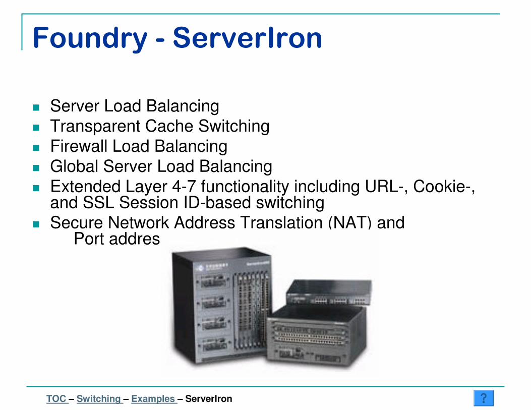
Foundry - ServerIron
� Server Load Balancing
� Transparent Cache Switching
� Firewall Load Balancing
� Global Server Load Balancing
� Extended Layer 4-7 functionality including URL-, Cookie-, and SSL Session ID-based switching
� Secure Network Address Translation (NAT) and Port address translation (PAT)
TOC – Switching – Examples – ServerIron

Architectures
� Generic Architecture
� First Generation
� Second Generation
� Third Generation
� Input Functions
� Output Functions
� Interconnection Designs� OUT� IN� VOB� Combined IN/OUT
TOC – Switching – Architectures
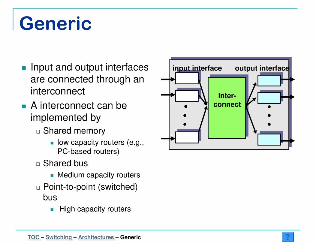
Generic
� Input and output interfaces
are connected through an
interconnect
� A interconnect can be
implemented by
� Shared memory
� low capacity routers (e.g.,
PC-based routers)
� Shared bus
� Medium capacity routers
� Point-to-point (switched)
bus
� High capacity routers
input interface output interface
Inter-
connect
TOC – Switching – Architectures – Generic
Route
TableCPU
Buffer
Memory
LineInterface
MAC
LineInterface
MAC
LineInterface
MAC
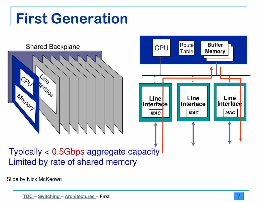
Typically < 0.5Gbps aggregate capacityLimited by rate of shared memory
Shared Backplane
Line Interface
CPU
Mem
ory
Slide by Nick McKeown
First Generation
TOC – Switching – Architectures – First
Route
TableCPU
LineCard
BufferMemory
LineCard
MAC
BufferMemory
LineCard
MAC
BufferMemory
FwdingCache
FwdingCache
FwdingCache
MAC
BufferMemory
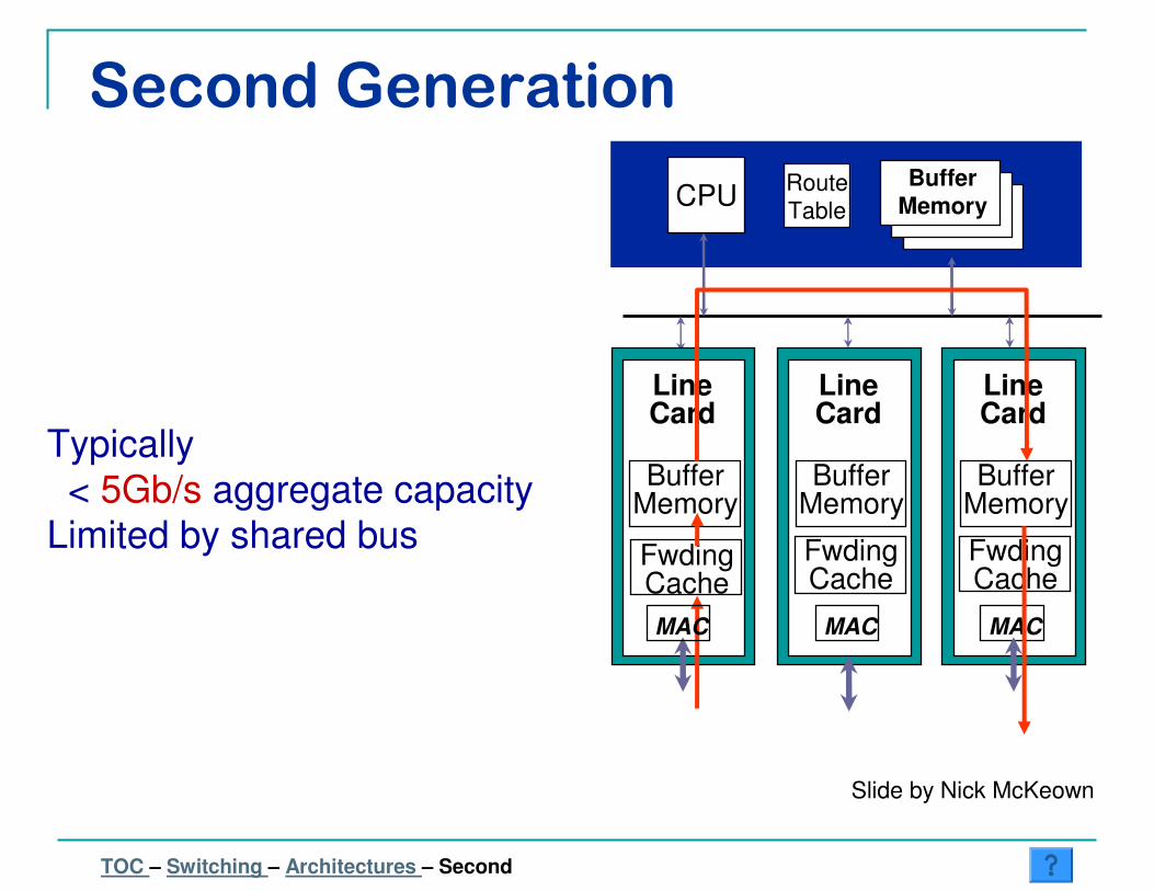
Typically
< 5Gb/s aggregate capacityLimited by shared bus
Slide by Nick McKeown
Second Generation
TOC – Switching – Architectures – Second
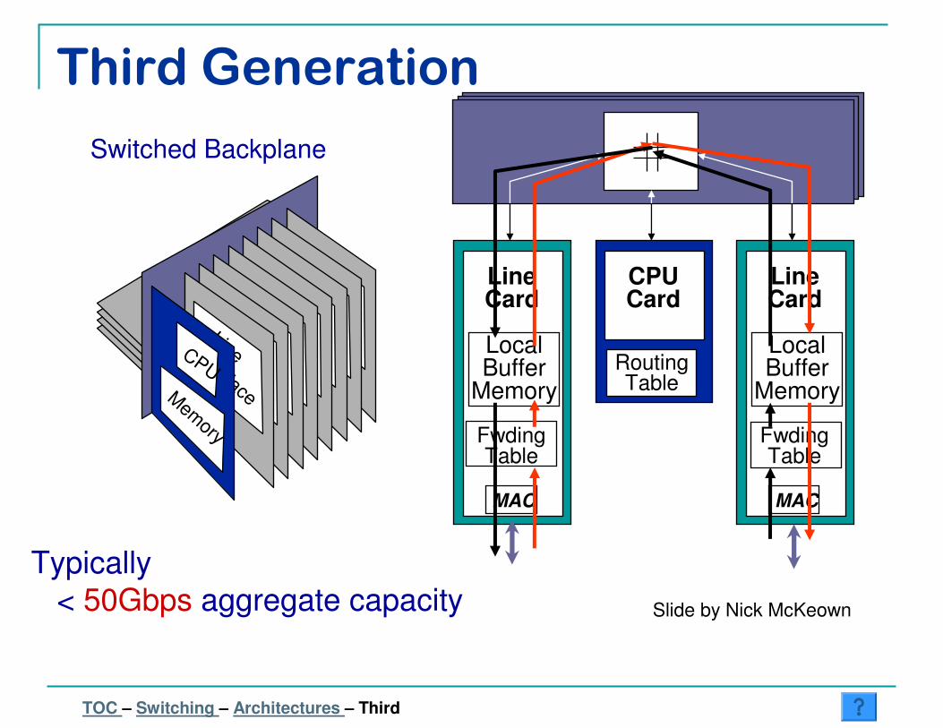
LineCard
MAC
LocalBuffer
Memory
CPUCard
LineCard
MAC
LocalBuffer
Memory
Switched Backplane
Line Interface
CPU
Mem
ory FwdingTable
RoutingTable
FwdingTable
Typically
< 50Gbps aggregate capacity Slide by Nick McKeown
Third Generation
TOC – Switching – Architectures – Third
Input Functions
� Packet forwarding: decide to which output
interface to forward each packet based on the
information in packet header
�examine packet header
� lookup in forwarding table
�update packet header
TOC – Switching – Architectures – Input Functions

Output Functions� Buffer management: decide when and
which packet to drop
� Scheduler: decide when and which
packet to transmit
1
2
Scheduler
Buffer
TOC – Switching – Architectures – Output Functions
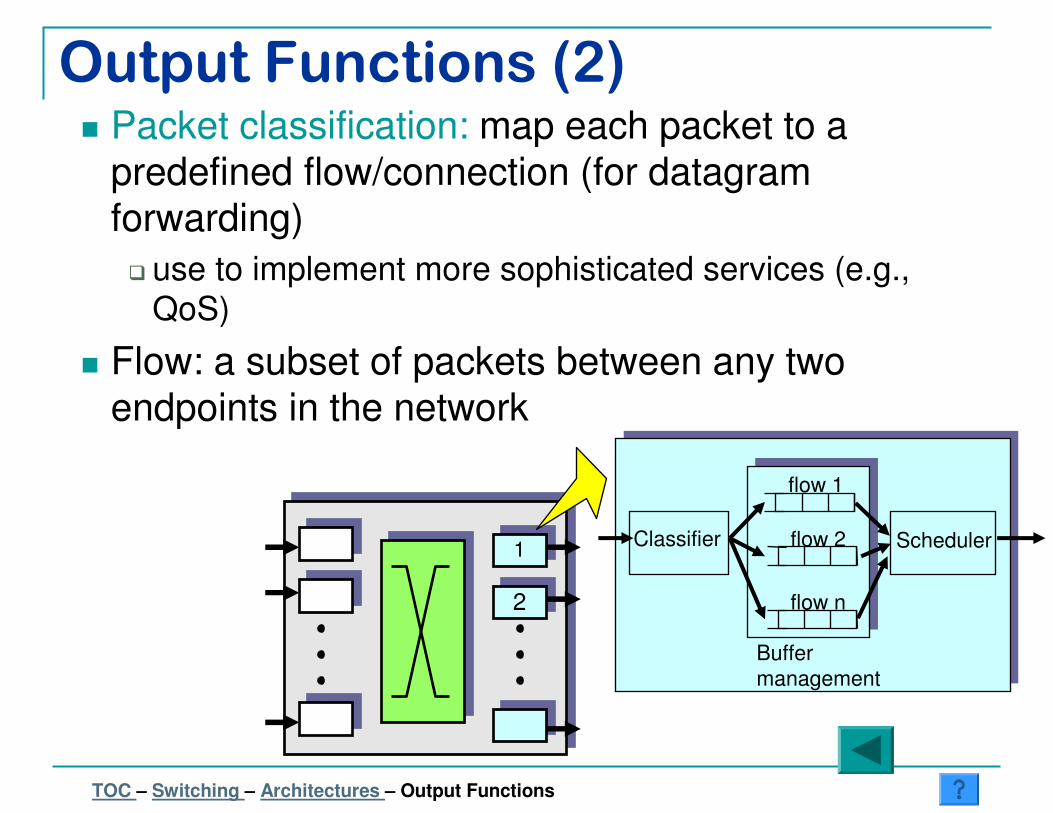
Output Functions (2)� Packet classification: map each packet to a
predefined flow/connection (for datagram forwarding)
� use to implement more sophisticated services (e.g.,
QoS)
� Flow: a subset of packets between any two endpoints in the network
1
2
Scheduler
flow 1
flow 2
flow n
Classifier
Buffer
management
TOC – Switching – Architectures – Output Functions

Output Queued � Only output interfaces
store packets
� Advantage
� Easy to design
algorithms: only one
congestion point
� Disadvantage
� Requires an output
speedup Ro/C = N, where
N is the number of
interfaces � not feasible
for large N
input interface output interface
Backplane
CRO
TOC – Switching – Architectures – Output Queued
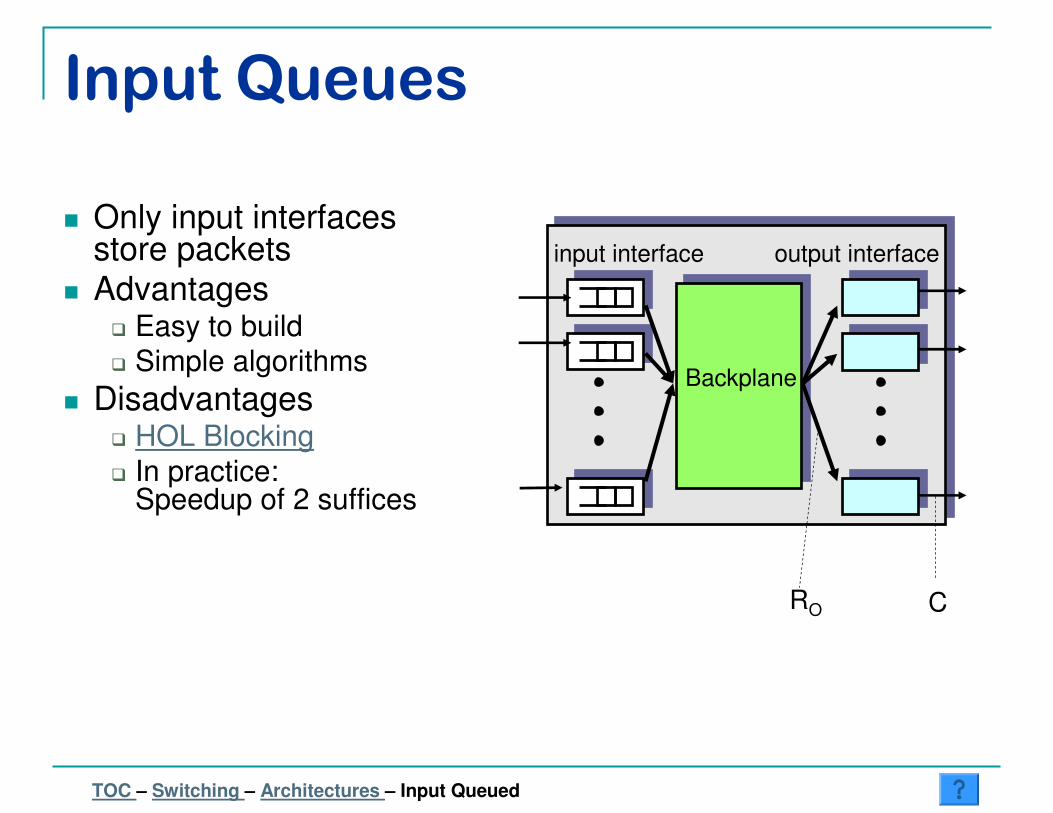
Input Queues
� Only input interfaces store packets
� Advantages� Easy to build� Simple algorithms
� Disadvantages� HOL Blocking
� In practice:Speedup of 2 suffices
input interface output interface
Backplane
CRO
TOC – Switching – Architectures – Input Queued
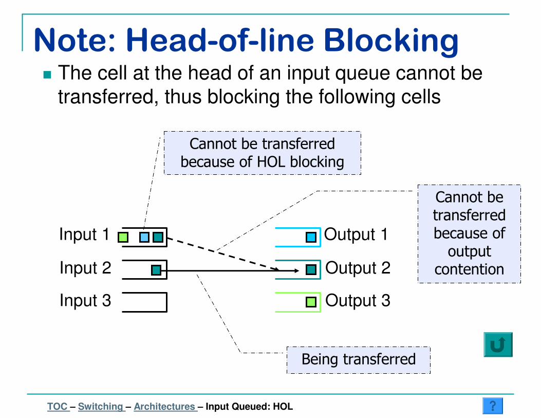
Note: Head-of-line Blocking� The cell at the head of an input queue cannot be
transferred, thus blocking the following cells
Output 1
Output 2
Output 3
Input 1
Input 2
Input 3
Cannot be transferred because of output
contention
Being transferred
Cannot be transferred because of HOL blocking
TOC – Switching – Architectures – Input Queued: HOL
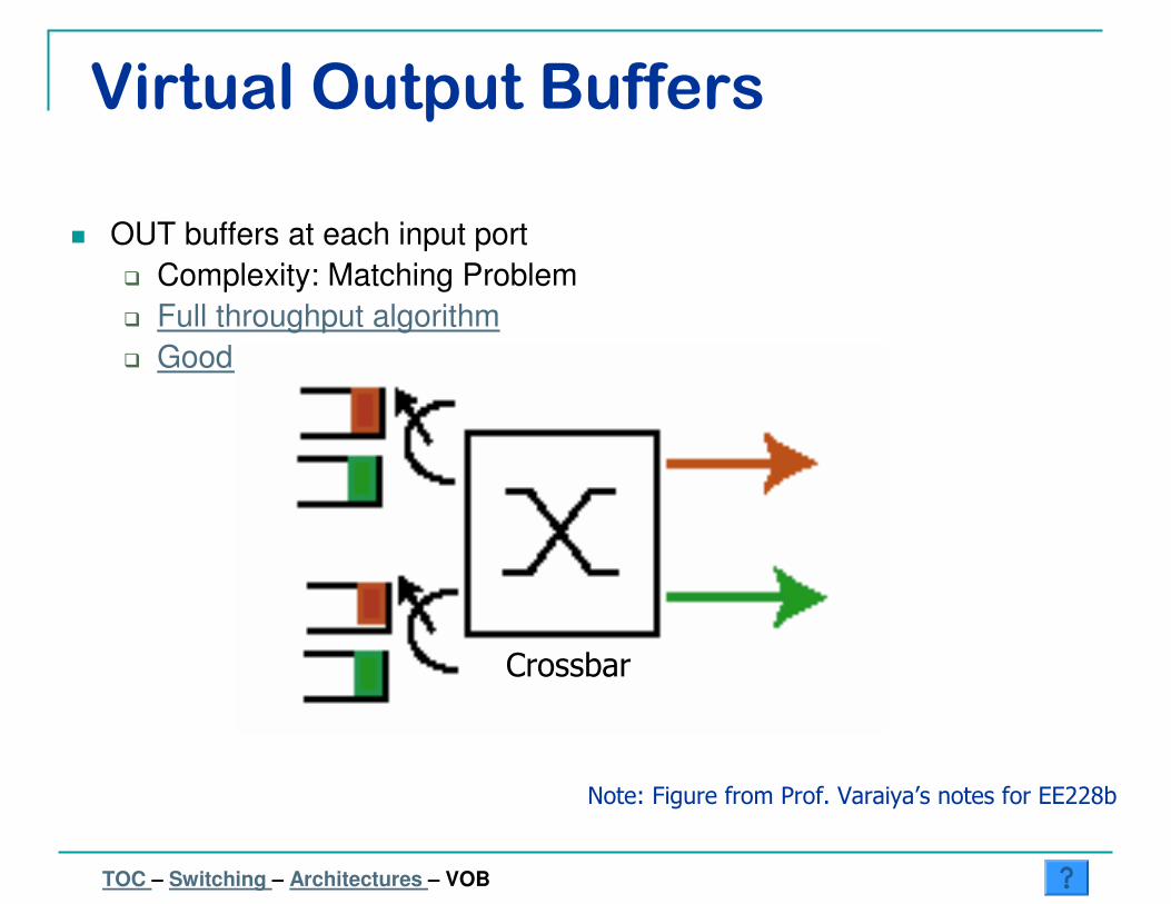
Virtual Output Buffers
� OUT buffers at each input port
� Complexity: Matching Problem
� Full throughput algorithm
� Good Heuristic
Note: Figure from Prof. Varaiya’s notes for EE228b
Crossbar
TOC – Switching – Architectures – VOB
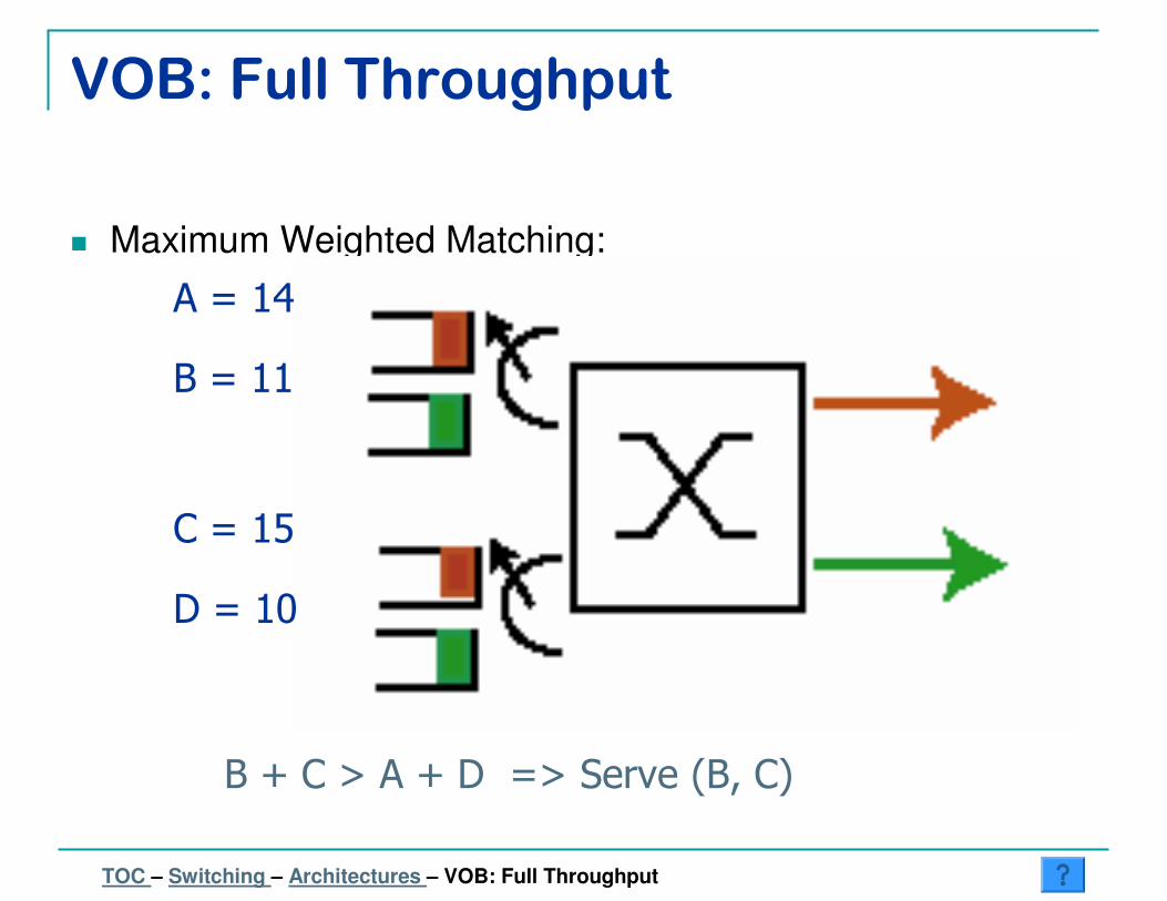
VOB: Full Throughput
� Maximum Weighted Matching:
A = 14
B = 11
C = 15
D = 10
B + C > A + D => Serve (B, C)
TOC – Switching – Architectures – VOB: Full Throughput

VOB: Good Heuristic – i-SLIP� Inputs request permission to send from outputs
� Outputs grant permissions to inputs (round-robin)
� Inputs accept permissions (round-robin)
Request Grant
2
1
3
3
1
2
Last GrantLast Accept
Accept Iter
TOC – Switching – Architectures – VOB: iSLIP
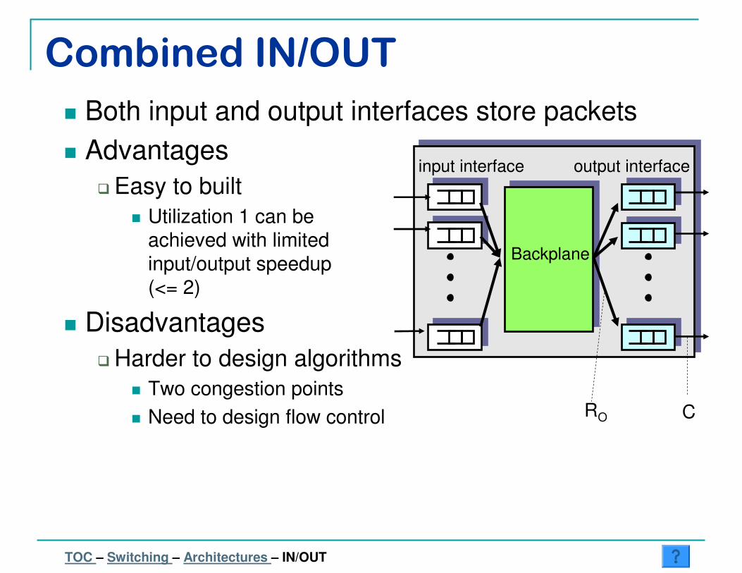
Combined IN/OUT
� Both input and output interfaces store packets
� Advantages
� Easy to built
� Utilization 1 can be
achieved with limited
input/output speedup
(<= 2)
� Disadvantages
� Harder to design algorithms
� Two congestion points
� Need to design flow control
input interface output interface
Backplane
CRO
TOC – Switching – Architectures – IN/OUT

� Switching needed for big networks
� Internetworking externality
� Circuit
� Packet – VC: QoS possible
� Packet – Datagram� L2: Limited by flat address space� L3:
� Exact Match: Easy lookup – less efficient
� Longest Prefix Match
� Switch functions: control and data
� Different Architectures: � cost vs. performance
Summary
TOC – Switching – Summary