Switchgear Testing - Inlec · ACTAS Switchgear Testing Operating Instructions ACTAS P260|P360 Test...
40
ACTAS Switchgear Testing Operating Instructions ACTAS P260|P360 Test Systems KoCoS Messtechnik AG Suedring 42 34497 Korbach, Germany Phone +49 5631 9596-40 [email protected] www.kocos.com
Transcript of Switchgear Testing - Inlec · ACTAS Switchgear Testing Operating Instructions ACTAS P260|P360 Test...
ACTAS Switchgear Testing
Operating Instructions
ACTAS P260|P360 Test Systems
KoCoS Messtechnik AG
Suedring 42
34497 Korbach, Germany Phone +49 5631 9596-40 [email protected] www.kocos.com

Operating Instructions ACTAS P260|P360
ACTAS P260 and P360 switchgear test systems
Doc. 7212201 – Rev. 1.00 SR1 2
Contents
1 ACTAS P260 and P360 switchgear test systems .................................................................................... 4
1.1 Flexible, compact switchgear test systems .................................................................................4 2 About this document ......................................................................................................................... 5
2.1 Other applicable documents ....................................................................................................5 2.2 Validity of the present document ..............................................................................................5 2.3 Warning marks and symbols ....................................................................................................5 2.4 Typographical conventions ......................................................................................................5 2.5 Basic safety information ..........................................................................................................6
2.5.1 General information ................................................................................................. 6
2.5.2 Qualifications of operating personnel .......................................................................... 6
2.5.3 Intended use .......................................................................................................... 6
2.5.4 Safe operation ........................................................................................................ 7
2.5.5 Personal protective equipment .................................................................................. 7
3 Commissioning ................................................................................................................................ 8
3.1 Transport and storage ............................................................................................................8 3.2 Unpacking the test system ......................................................................................................8 3.3 Requirements to be fulfilled by the installation location ................................................................8
4 Overview ........................................................................................................................................ 9
4.1 ACTAS P260 ..........................................................................................................................9 4.2 ACTAS P360 ..........................................................................................................................9 4.3 Touch screen....................................................................................................................... 10 4.4 Function keys ...................................................................................................................... 10
5 Connect the test system ................................................................................................................... 11
5.1 Connection to power supply................................................................................................... 11 6 Connect the device to be tested ........................................................................................................ 11
6.1 PIR and main contacts .......................................................................................................... 12 6.2 Auxiliary contacts ................................................................................................................ 12 6.3 Travel transducers and sensors .............................................................................................. 13
6.3.1 ACTAS P360 .......................................................................................................... 13
6.3.2 ACTAS P260 .......................................................................................................... 13
6.4 Coil/motor/station voltage and motor current ........................................................................... 13 6.4.1 ACTAS P360 .......................................................................................................... 13
6.5 Electronic control outputs ...................................................................................................... 14 7 Connect peripherals ......................................................................................................................... 15
7.1.1 PC interfaces ......................................................................................................... 15
7.1.2 Interfaces for external devices ................................................................................. 15
7.1.3 Digital Control ....................................................................................................... 15
8 General settings .............................................................................................................................. 16
8.1 User data ........................................................................................................................... 16 8.2 Time .................................................................................................................................. 16 8.3 Network ............................................................................................................................. 17 8.4 Language and phase scheme ................................................................................................. 17 8.5 Appearance ......................................................................................................................... 17 8.6 Defaults ............................................................................................................................. 17

Operating Instructions ACTAS P260|P360
ACTAS P260 and P360 switchgear test systems
Doc. 7212201 – Rev. 1.00 SR1 3
9 Settings for the switchgear device ..................................................................................................... 18
9.1 Assets database .................................................................................................................. 18 9.2 Type catalog ....................................................................................................................... 19
9.2.1 Create a new switchgear device................................................................................ 19
9.3 Configure switchgear devices ................................................................................................. 19 9.3.1 Nameplate ............................................................................................................ 19
9.3.2 Construction .......................................................................................................... 20
9.3.3 Connections .......................................................................................................... 21
9.3.4 Tests .................................................................................................................... 24
9.3.5 Evaluation ............................................................................................................. 25
10 Test .............................................................................................................................................. 26
10.1 Select a switchgear device .................................................................................................... 26 10.2 Select test function .............................................................................................................. 26 10.3 Subsequently edit test parameters ......................................................................................... 27
10.3.1 Timing test function ................................................................................................ 28
10.3.2 Contact resistance test function ................................................................................ 29
10.3.3 Drive test function .................................................................................................. 31
11 Analyse tests .................................................................................................................................. 33
11.1 Select tests ......................................................................................................................... 33 11.2 Result display ...................................................................................................................... 34
11.2.1 Delete and export recordings ................................................................................... 34
11.2.2 Change parameters for evaluation ............................................................................ 35
11.2.3 Help functions for evaluation .................................................................................... 35
12 Maintenance and service ....................................................................................................... 37 12.1 Cleaning ............................................................................................................... 37
12.2 Servicing .............................................................................................................. 37
12.3 Calibration ............................................................................................................ 37
13 Guarantee conditions ........................................................................................................... 38 13.1 Calibration confirmation .......................................................................................... 38
14 Technical data ................................................................................................................................ 39
14.1.1 Control outputs ...................................................................................................... 39
14.1.2 Measurement inputs ............................................................................................... 39
Copyright © 2016 by KoCoS Messtechnik AG. All rights reserved.
No part of this document may be reproduced or processed, duplicated or distributed using electronic systems in any form (print, photocopy, microfilm or other method) without the prior written consent of KoCoS Messtechnik AG.
KoCoS Messtechnik AG is not liable for damage resulting from misuse, nor for repairs and alterations made by unauthorized third parties. This document has been produced with great care. However, KoCoS Messtechnik AG does not accept liability for errors due to negligence.
Note: all the product names which appear in this document are brands of the companies concerned.
Even if a trademark symbol ® or ™ is not given, it does not necessarily follow that a term used in this document is not a brand name.
Operating Instructions ACTAS P260|P360
ACTAS P260 and P360 switchgear test systems
Doc. 7212201 – Rev. 1.00 SR1 4
1 ACTAS P260 and P360 switchgear test systems
1.1 Flexible, compact switchgear test systems
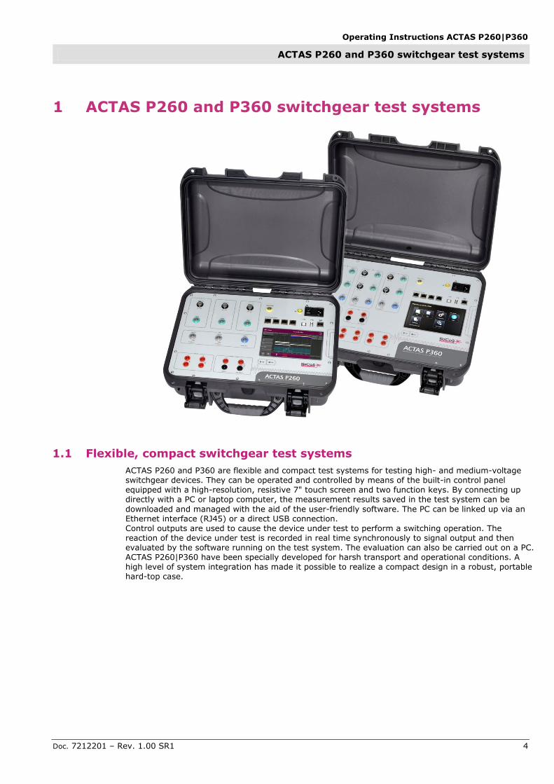
ACTAS P260 and P360 are flexible and compact test systems for testing high- and medium-voltage switchgear devices. They can be operated and controlled by means of the built-in control panel equipped with a high-resolution, resistive 7" touch screen and two function keys. By connecting up directly with a PC or laptop computer, the measurement results saved in the test system can be
downloaded and managed with the aid of the user-friendly software. The PC can be linked up via an Ethernet interface (RJ45) or a direct USB connection. Control outputs are used to cause the device under test to perform a switching operation. The reaction of the device under test is recorded in real time synchronously to signal output and then evaluated by the software running on the test system. The evaluation can also be carried out on a PC. ACTAS P260|P360 have been specially developed for harsh transport and operational conditions. A high level of system integration has made it possible to realize a compact design in a robust, portable hard-top case.

Operating Instructions ACTAS P260|P360
About this document
Doc. 7212201 – Rev. 1.00 SR1 5
2 About this document
These operating instructions describe how to commission, connect, operate, control and maintain ACTAS P260|P360 switchgear test systems.
This user manual is intended for:
Persons who know how to switch on and off, enable, earth and identify electrical circuits and devices/systems in accordance with the applicable safety standards
Trained operating personnel in electrical installations
2.1 Other applicable documents
A number of other documents apply in conjunction with these operating instructions. The manufacturer is not liable for damages resulting from failure to comply with information contained in any of these documents.
All documentation pertaining to the commissioning, configuration of settings, operation and maintenance of ACTAS P260|P360 switchgear test systems also applies.
2.2 Validity of the present document
These operating instructions apply only to switchgear test system with the type designation ACTAS P260 and ACTAS P360.
The type designation and the serial number of the test system are detailed on the rating plate.
2.3 Warning marks and symbols
Symbol Explanation
DANGER
This symbol indicates the presence of an immediate risk associated with electric voltage. If this risk is not avoided, death or serious injury may result.
CAUTION
This symbol indicates the presence of a potential risk associated with improper use. If this risk is not avoided, personal injuries or material damage may result.
NOTE
This symbol highlights notes and information.
2.4 Typographical conventions
Symbol Explanation
This symbol highlights instructions which require action on the part of the user
1.
2. Numbered lists are used for actions which must be carried out in the order given
This symbol marks the items of a list

Operating Instructions ACTAS P260|P360
About this document
Doc. 7212201 – Rev. 1.00 SR1 6
2.5 Basic safety information
CAUTION
The safety information and regulations detailed below must be complied with! The relevant regulations issued by the appropriate institutions for statutory accident insurance and prevention (professional and trade associations) must be followed.
2.5.1 General information
DANGER
Failure to comply with safety information, incorrect use of the test system, or use other than the intended use can endanger property and personnel and result in damage or injury.
These operating instructions must be read and understood in full before the test system is put into operation. They must be kept for future reference and be made available to anyone who uses the
test system throughout its operational life.
2.5.2 Qualifications of operating personnel
The test system is only to be used by qualified personnel in accordance with safety rules and regulations. The statutory provisions and safety regulations for the specific application must also
be observed when using the test system. The term "qualified personnel" refers to persons who are familiar with the set-up, commissioning and operation of the product and who have appropriate qualifications:
Training or instruction and authorization to switch on and off, isolate, earth and mark accordingly electrical circuits and devices in accordance with safety standards
Instruction in accordance with the regulations of the appropriate institutions for statutory accident insurance and prevention (professional and trade associations)
Safety standards in the care and use of appropriate safety equipment
2.5.3 Intended use
The test system is manufactured in accordance with the state of the art and recognized safety rules.
However, improper use or use other than the intended use can endanger the life and limb of users or third parties and cause damage to the test system or other property.
The manufacturer is not liable for consequential damage arising as a result of use other than the intended use. Any claims under the guarantee are void.
No modifications may be made to the test system other than those which are described in this document or in the other applicable documents.
The test system may only be used for the applications listed below:
Function test for switchgear devices
Dynamic determination of resistances and contact times in combination with PROMET SE ohm meters
Function test of switchgear device components in combination with the EPOS MC3 motor and coil test system.

Operating Instructions ACTAS P260|P360
About this document
Doc. 7212201 – Rev. 1.00 SR1 7
2.5.4 Safe operation
If there is any reason to suppose that the test system cannot be operated without risk, it must be put out of operation immediately and secured against unintended start-up. This applies if, for example:
- there is obvious damage to the test system or accessories.
- the test system or accessories do not work properly although the power supply is intact.
- the test system or accessories have been exposed to unfavourable conditions for a significant length of time (e.g. storage at temperature and humidity levels which are beyond the permissible limits without gradual adjustment to the indoor environment, condensation or other similar conditions).
- the test system or accessories have been exposed to undue transport stresses even if there is no visible external damage.
2.5.5 Personal protective equipment
The regulations on personal protective equipment laid down by the company operating the test system at the installation location apply. No additional protective equipment is required.

Operating Instructions ACTAS P260|P360
Commissioning
Doc. 7212201 – Rev. 1.00 SR1 8
3 Commissioning
The test system may only be put into operation by specialist staff who have received appropriate instruction from the manufacturer.
Proper transport, specialist storage, set-up and commissioning and careful operation, maintenance and servicing are essential in order for this test system to function perfectly and safely.
Check that the delivery is complete and was not damaged during transport. Do not put the test system into operation if there is any damage.
3.1 Transport and storage
The following regulations apply for the transport and storage of the tests system:
Keep upright; avoid strong vibrations and
mechanical influences
Keep the test system dry
Protect the test system from direct sunlight
and heat
3.2 Unpacking the test system
The measuring device must be unpacked with care. Suitable tools are to be used. We recommend that the original packaging be retained for subsequent transport.
Check the packing list to make sure no items are missing
Perform a visual inspection to check that the test system is in perfect condition
3.3 Requirements to be fulfilled by the installation location
Impermissible environmental conditions may result in damage to the test system and
jeopardize safe operation
Ensure environmental conditions conform to the technical data specified
Avoid air pollution
Avoid high levels of air humidity
The test system is not protected against the ingress of moisture. Damp and wetness can damage the test system and cause dangerous short circuits
When the test system is moved from a cold environment into a warm one, condensation can be a source of danger
DANGER Gases may ignite as a result of sparking which may occur while connecting or operating the test system. Do not use the test system in environments with explosive gases, vapours or dust.
Operating Instructions ACTAS P260|P360
Overview
Doc. 7212201 – Rev. 1.00 SR1 9
4 Overview
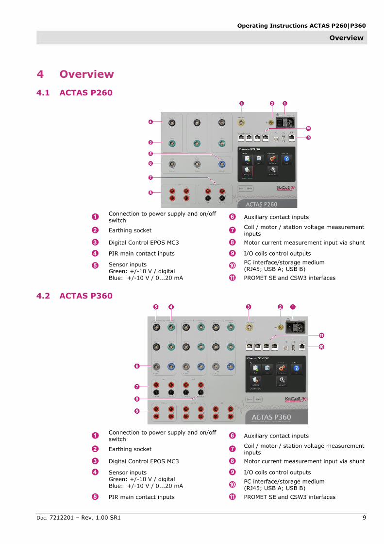
4.1 ACTAS P260
Connection to power supply and on/off switch Auxiliary contact inputs
Earthing socket Coil / motor / station voltage measurement inputs
Digital Control EPOS MC3 Motor current measurement input via shunt
PIR main contact inputs I/O coils control outputs
Sensor inputs Green: +/-10 V / digital Blue: +/-10 V / 0...20 mA
PC interface/storage medium (RJ45; USB A; USB B)
PROMET SE and CSW3 interfaces
4.2 ACTAS P360
Connection to power supply and on/off switch Auxiliary contact inputs
Earthing socket Coil / motor / station voltage measurement inputs
Digital Control EPOS MC3 Motor current measurement input via shunt
Sensor inputs Green: +/-10 V / digital Blue: +/-10 V / 0...20 mA
I/O coils control outputs
PC interface/storage medium (RJ45; USB A; USB B)
PIR main contact inputs PROMET SE and CSW3 interfaces

Operating Instructions ACTAS P260|P360
Overview
Doc. 7212201 – Rev. 1.00 SR1 10
4.3 Touch screen
The resistive touch screen reacts to pressure and can therefore also be operated when wearing gloves, for example.
To avoid damage, never use hard or sharp objects to operate the touch screen!
Using the built-in touch screen, it is possible to
carry out all the tasks connected with operation and configuration. The measurement results obtained are displayed and an analysis of the results can be carried out directly on the test system itself.
The functions fall into three categories:
Operate - Test - Create and edit switchgear - Create and edit jobs Administrate - Configure ACTAS - Carry out service such as updates etc. Help & Info
- Info such as user manuals etc.
4.4 Function keys
The function keys OK und ESC are used to
navigate forward/reverse through the menus and to start/cancel tests.

Operating Instructions ACTAS P260|P360
Connect the test system
Doc. 7212201 – Rev. 1.00 SR1 11
5 Connect the test system
5.1 Connection to power supply
The test system is supplied with power via the mains connection socket using the cable for non-heating appliances provided. The earthing socket can be used to connect the test system with the station earth, for example.
Incorrect connection to the power supply can cause death or injury from electric shock!
The system housing is earthed via the connection to the power supply. Make sure that the
connection to the power supply has an earth continuity conductor. The earth connection should never be interrupted, either inside or outside the test system. Never use an extension cord without an earth continuity conductor, for example. Always check the earth connection before starting up the device.
The test system should always be connected with the station earth via the separate earthing socket.
Operating the test system with an incorrect power supply voltage may damage it and leads to loss of the guarantee.
The test system may only be operated within the power supply voltage range detailed on the rating plate.
Check the voltage and frequency of the power supply before connecting the test system to the power supply.
6 Connect the device to be tested
Make sure the test system is switched off before connecting a device to be tested
The device to be tested may only be connected to or disconnected from the test system when it is absolutely certain that no test values are available at the outputs
For reasons of safety, only measuring leads with plugs which are safe to touch may be used. The
measuring leads must be fully insulated. During tests, high voltages which are life-threatening if touched are sometimes present at the output sockets
Test cables, sockets and plugs much be checked for cracks, breaks, or faulty insulation before use, check the continuity of the measuring leads and replace any which are damaged, also check the insulation of the measurement sockets
Only use measuring leads which can be firmly fixed to the device to be tested by means of plug-in contacts, clamps or cable lugs
Use measuring leads which are as short as possible. Particularly when connecting the operating coils and the measuring loop for the motor current measurement, it is essential to check the correct dimensioning of the conductor cross-sections
Remove any superfluous measuring leads
During connection, the drive unit should be put out of operation by interrupting the power
supply, for example. In addition, all drive energy should be discharged in the case of drives with an energy storage mechanism (spring, hydraulic or pneumatic)

Operating Instructions ACTAS P260|P360
Connect the device to be tested
Doc. 7212201 – Rev. 1.00 SR1 12
6.1 PIR and main contacts
Fig.: ACTAS P360 with four PIR and main contact inputs per
pole
To determine the operating times of the individual
interrupter units, the status of the main contacts can be captured for poles A, B and C via four PIR and four main contact inputs (with ACTAS P260 via two PIR and two main contact inputs). Using the same inputs it is also possible to carry out a PIR measurement to record the resistance characteristic of the closing resistors.
R < 30 Ω Main and resistive contact closed
30 Ω < R < 10 kΩ Resistive contact closed
R > 10 kΩ Main and resistive contact open
Fig.: ACTAS P260 with two PIR and main contact inputs per
pole
6.2 Auxiliary contacts
Fig.: ACTAS P360 with twelve auxiliary contact inputs
The status of the auxiliary contacts of a switchgear
device can be recorded via the auxiliary contact inputs. With ACTAS P360 it is possible to record 12 auxiliary contacts, with ACTAS P260 it is possible to record 8 auxiliary contacts.
The test systems feature internal switching for wet auxiliary contacts or voltage provision by ACTAS, see the section of these operating instructions titled
Settings for the switchgear device.
The auxiliary voltage supplied by ACTAS is 24 VDC. The input signal range is between 24 and 300 VDC.
Fig.: ACTAS P260 with eight auxiliary contact inputs

Operating Instructions ACTAS P260|P360
Connect the device to be tested
Doc. 7212201 – Rev. 1.00 SR1 13
6.3 Travel transducers and sensors
6.3.1 ACTAS P360
ACTAS P360 features 9 travel transducer and sensor inputs. It is possible to connect analog as well as incremental sensors to the Sensor 1 and Sensor 2 connections. 10 VDC inputs are available for the analog sensors, appropriate digital inputs are
available for the incremental sensors. It is also possible to connect two different types of sensor to the Sensor 3 connection. For this purpose, a 10 VDC measurement input and a 0…20 mA measurement input are available. ACTAS P360 has a stabilized reference voltage of 10 VDC to supply the travel transducers and sensors.
6.3.2 ACTAS P260
ACTAS P260 features 4 travel transducer and sensor inputs. It is possible to connect analog as well as incremental sensors to the connections for poles A/B/C (green). 10 VDC inputs are available for the analog sensors, appropriate digital inputs are available for the incremental sensors. It is also possible to connect two different types of sensor to the blue connection. For this purpose, a 10 VDC measurement input and a 0…20 mA
measurement input are available. ACTAS P260 has a stabilized reference voltage of 10 VDC to supply the travel transducers and sensors.
6.4 Coil/motor/station voltage and motor current
6.4.1 ACTAS P360
Fig.: ACTAS P360 with three voltage measurement inputs
Fig.: ACTAS P260 with one universal voltage measurement
input
ACTAS P360 also offers the option of recording three
voltages during a switchgear test. Two measurement inputs with a measuring range up to max. 300 VAC and one measurement input with a measuring range of up to max. 500 VAC are provided for this purpose.
ACTAS P260 has one universal measurement input with a measuring range of up to max. 500 VAC.
With P260 and P360 the motor current can be measured directly via a shunt which is integrated in the test system. The current measurement has a
measuring range of up to 100 AAC.
During the current measurement, the 4 mm safety sockets may only be applied with up to 100 AAC for short periods, less than 1 s. The rated current is 32 A.

Operating Instructions ACTAS P260|P360
Connect the device to be tested
Doc. 7212201 – Rev. 1.00 SR1 14
6.5 Electronic control outputs
Fig.: ACTAS P360 with control outputs for three closing- and
three opening coils
Fig.: ACTAS P260 with control outputs for one closing and one
opening coil
Electronic control outputs (IGBTs) with which d.c. and a.c. voltage coils can be operated are used to operate the switching coils. One opening and one closing coil can be controlled for each phase. The electronic control outputs are able to achieve a much higher degree of accuracy than would be possible with conventional relay outputs. The closing/opening delay of the electronic outputs amounts to just one microsecond.
The coil operating currents are measured using shunts integrated in the test system with a maximum measuring range of 100 AAC. The currents in the closing and opening circuit are galvanically isolated for each phase, but are measured on a common analog input. It is therefore possible to supply close and open circuits with electricity from different electrical circuits.
During the current measurement, the 4 mm safety sockets may only be applied with up to 100 AAC for short periods, less than 1 s. The rated current is 32 A.

Operating Instructions ACTAS P260|P360
Connect peripherals
Doc. 7212201 – Rev. 1.00 SR1 15
7 Connect peripherals
7.1.1 PC interfaces
USB interfaces
The passive USB B interface is used for communication with a PC or laptop, the active USB A
interface is used for communication with a storage medium, to archive test device data or test reports, for example. It is also possible to operate a specific
printer on this interface.
Ethernet interface
The RJ45 interface serves to connect the test system to a network or PC.
7.1.2 Interfaces for external devices
External Device Control
Using further RJ45 interfaces it is possible to integrate up to 3 PROMET SE ohm meters, or up to 6 PROMET SE ohm meters when a CSW 3 connection unit is in use. The measuring devices are controlled by ACTAS. This makes it possible to carry out dynamic resistance measurements on 3 poles with two interrupter units each. When PROMET SE
devices are involved, switchgear tests can be carried out with earthing on both sides.
7.1.3 Digital Control
The Digital Control interface allows the connection of the motor and coil test system EPOS MC3.

Operating Instructions ACTAS P260|P360
General settings
Doc. 7212201 – Rev. 1.00 SR1 16
8 General settings
The general settings and the sensor library can be
found in the Administrate function group, under Configuration
Under General Settings, settings can be made for
user data, time, network, language and appearance as well as for defaults.
When a user exits the general settings, a message is shown asking whether or not any changes are to be saved. Some changes also require the system to be restarted. If so, a message is displayed to this effect.
8.1 User data
Enter user data
The user data entered here appears in test reports.
8.2 Time
Set the system time
The system time appears in test reports.
Operating Instructions ACTAS P260|P360
General settings
Doc. 7212201 – Rev. 1.00 SR1 17
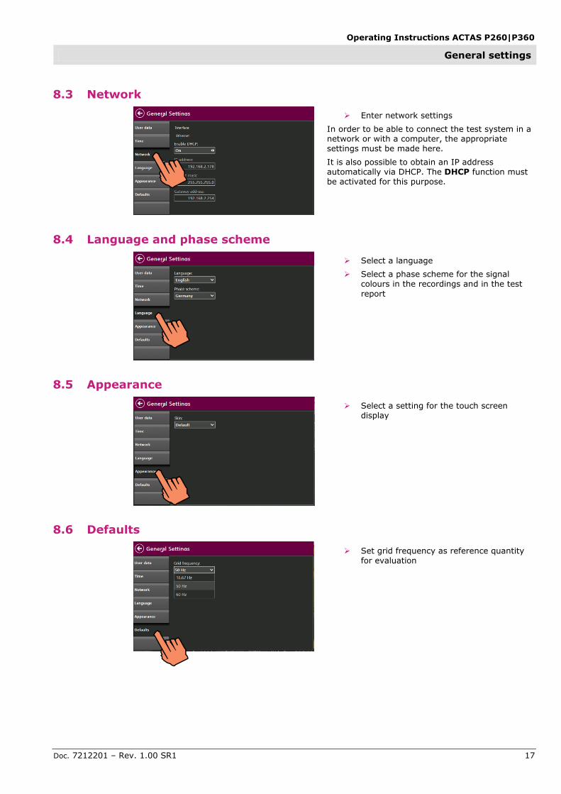
8.3 Network
Enter network settings
In order to be able to connect the test system in a network or with a computer, the appropriate settings must be made here.
It is also possible to obtain an IP address automatically via DHCP. The DHCP function must be activated for this purpose.
8.4 Language and phase scheme
Select a language
Select a phase scheme for the signal colours in the recordings and in the test
report
8.5 Appearance
Select a setting for the touch screen display
8.6 Defaults
Set grid frequency as reference quantity for evaluation

Operating Instructions ACTAS P260|P360
Settings for the switchgear device
Doc. 7212201 – Rev. 1.00 SR1 18
9 Settings for the switchgear device
The assets database and type catalog can be found
in the Operate function group, under Switchgear.
9.1 Assets database
All the switchgear devices on which measurements
have already been carried out are listed in the assets database. The switchgear devices listed can be sorted according to various different criteria.
Switchgear devices can be added, deleted or saved on a storage medium.
A search function allows selected specific switchgear devices to be selected in a switchgear list or in the network topology, for example.
Operating Instructions ACTAS P260|P360
Settings for the switchgear device
Doc. 7212201 – Rev. 1.00 SR1 19
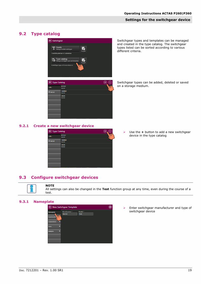
9.2 Type catalog
Switchgear types and templates can be managed
and created in the type catalog. The switchgear types listed can be sorted according to various different criteria.
Switchgear types can be added, deleted or saved
on a storage medium.
9.2.1 Create a new switchgear device
Use the + button to add a new switchgear device in the type catalog
9.3 Configure switchgear devices
NOTE All settings can also be changed in the Test function group at any time, even during the course of a test.
9.3.1 Nameplate
Enter switchgear manufacturer and type of switchgear device

Operating Instructions ACTAS P260|P360
Settings for the switchgear device
Doc. 7212201 – Rev. 1.00 SR1 20
9.3.2 Construction
The main circuit, coils and drives of the device under test are defined under Construction.
Main circuit
Select the number of poles
Select the number of modules (example: a double T breaker has two modules, see below)
Select the number of interrupter units per module
Activate the check box if there are closing resistors
Nomenclature in the main circuit
Coils
Select the number of closing and opening coils
Select signal form, can be switched between AC and DC
Interrupter unit 2
Interrupter unit 1
Pole C
Pole B
Pole A
Module 1 Module 2

Operating Instructions ACTAS P260|P360
Settings for the switchgear device
Doc. 7212201 – Rev. 1.00 SR1 21
Drives
Select the number of drives
Select signal form, can be switched between AC and DC
9.3.3 Connections
Under Connections, the test mode is set for the main contacts and the components to be connected, such as auxiliary contacts, sensors, coils and motors, are configured.
Fig.: ACTAS P360
Main contacts
Select test mode, see below
Internal
PROMET SE
Fig.: ACTAS P360
Select connection mode
Only those connection modes defined under
Construction/Main circuit are displayed here.
Pole The measurement is made across the entire pole, i.e. all interrupter units of the pole are included in one result.
Module The measurement is made across the entire module, i.e. all interrupter units of the module are included in one result.
Unit The measurement is made on each
individual interrupter unit.

Operating Instructions ACTAS P260|P360
Settings for the switchgear device
Doc. 7212201 – Rev. 1.00 SR1 22
Fig.: ACTAS P360
Internal test mode
Select the Internal test mode if a test is to be carried out without additional
components
The connections for the main contacts are displayed.
Fig.: ACTAS P360
Status display for internal test mode The status of the main and resistive contacts is shown on the status display in the Internal test mode.
Fig.: ACTAS P360
PROMET SE test mode PROMET SE devices connected with ACTAS are displayed under Devices.
Set the test current
Set expected voltage measuring range

Operating Instructions ACTAS P260|P360
Settings for the switchgear device
Doc. 7212201 – Rev. 1.00 SR1 23
Fig.: ACTAS P360
Auxiliary contacts
Select a connection scheme
Select contacts per switchgear
Select whether voltage for auxiliary contacts is provided by ACTAS or whether the auxiliary contacts are wet
Fig.: ACTAS P360
Travel
Select travel transducers
Sensors created beforehand can be integrated and it is possible to create sensors directly.
The current values of the sensors are displayed under Status.
Fig.: ACTAS P360
Sensors
Select sensors
Sensors created beforehand can be integrated and it is possible to create sensors directly. The values of the transducers can be entered or edited directly. The current values of the sensors are displayed under Status
Fig.: ACTAS P360
Coils
Activate coil control and select current
measuring ranges (Maximum coil current 100 AAC)
Select voltage measurement
Fig.: ACTAS P360
Motors
Activate motor current measurement and
select measuring range (Maximum motor current 100 AAC)
Activate motor voltage measurement
The activation of the current measurement is blocked if a current measurement was already selected under Connections/Sensors during sensor configuration

Operating Instructions ACTAS P260|P360
Settings for the switchgear device
Doc. 7212201 – Rev. 1.00 SR1 24
9.3.4 Tests
The control sequences and the recordings desired for the test to be carried out are defined under Tests.
Select the test to be carried out
Set sampling rate (max. 30 kHz)
Set pre-trigger
Set record duration
Set control times for the individual control sequences

Operating Instructions ACTAS P260|P360
Settings for the switchgear device
Doc. 7212201 – Rev. 1.00 SR1 25
9.3.5 Evaluation
The parameters and reference methods for the evaluation of the recordings are defined under Analysis.
Close speed and Open speed
Define points for the calculation of the close and open speed
Various reference methods can be selected, such as at contact make or contact break or the absolute or relative stroke, for example.
Coils
Enter the beginning and the end value for
the calculation of the mean value relative to the current flow duration of the coil current
Drive
Enter the beginning and the end value for
the calculation of the mean value relative to the current flow duration of the motor current
Configuration is now complete.
Save the switchgear template

Operating Instructions ACTAS P260|P360
Test
Doc. 7212201 – Rev. 1.00 SR1 26
10 Test
All the functions for carrying out a switchgear test
can be found in the Operate function group under Test.
10.1 Select a switchgear device
A switchgear device must be selected at the
beginning of every test.
New switchgear
A new switchgear device can be created on the
basis of a switchgear template, for more information see the section of these operating instructions titled Settings for the switchgear device.
Open switchgear
A switchgear device can be called up from the
database as the basis for a new job.
Open job
It is also possible to open an existing test and to complete it, if required.
Select a switchgear device or an existing test
10.2 Select test function
Once the switchgear device is selected, the Select
Test Function window is called up.
Timing measurements, drive tests as well as static
and dynamic resistance measurements are saved as functions.
Test jobs can be edited or the test jobs which is still open can be completed.
If a test job is not completed, this test job is automatically called up until it is completed.

Operating Instructions ACTAS P260|P360
Test
Doc. 7212201 – Rev. 1.00 SR1 27
10.3 Subsequently edit test parameters
In any test function, test parameters can be edited
without having to quit the test job:
Tap the Execute button
The Parameter group is displayed in the status bar, any switchgear parameters can be directly edited.

Operating Instructions ACTAS P260|P360
Test
Doc. 7212201 – Rev. 1.00 SR1 28
10.3.1 Timing test function
In the Timing test function, the operating times for main contacts and auxiliary contacts can be tested with various switching sequences. In addition, the coil current as analog trace as well as signals from sensors and travel sensors are recorded.
Prepare tests
Select test sequences on the left-hand side
of the screen
Put the switchgear device into test position
The status display for the main contacts is located in the bottom right-hand corner: Green: Breaker open Red: Breaker closed By tapping the status display, the switchgear can be switched manually in order to move the contacts to the required test position.
Start the test
Press the OK key on the test system to start the test

Operating Instructions ACTAS P260|P360
Test
Doc. 7212201 – Rev. 1.00 SR1 29
10.3.2 Contact resistance test function
Used in combination with the PROMET SE ohm meter, both the static and the dynamic contact resistance can be determined simultaneously on three poles with two interrupter units each.
Fig.:PROMET SE connected to two interrupter units
Connect PROMET SE
Use the carrying strap to hang PROMET SE up on the main contact chamber
Connect PROMET SE to the interrupter units (4-wire method)
Use patch cables to connect PROMET SE to the External Device Control interfaces on the ACTAS P360
If more than six interrupter units are to be measured at the same time, the PROMET SE devices needed are to be connected to the fourth interface via the CSW3 connection unit.
Set PROMET SE
Use the ESC function key to switch to the
selection of the measuring mode
Select the measurement mode with PROMET and ACTAS
Measuring mode for the static (SRM) and dynamic (DRM) resistance measurement with PROMET and ACTAS.
Stand-alone measurement with PROMET.
PROMET SE is initialised for the measurement on the circuit breaker.
Make the settings for interrupter unit, module and pole. For more information, see
the section of these operating instructions titled Nomenclature in the main circuit
Use the OK key to switch to the stand-by mode
The display is switched off, PROMET SE is now ready for the measurement with ACTAS.
Interrupter unit 1 Interrupter unit 2
Module
Pole
Active Active

Operating Instructions ACTAS P260|P360
Test
Doc. 7212201 – Rev. 1.00 SR1 30
Set ACTAS
Call up the connection parameters for
main contacts
Set PROMET SE test mode
PROMET SE devices connected with ACTAS are displayed under Devices.
Set the test current
Set expected voltage measuring range
Wait until all PROMET SE devices have finished adjusting and the Ready for test status is displayed.
Dynamic resistance measurement DRM A dynamic contact resistance measurement determines the resistance characteristic during a CLOSE/OPEN switching operation. The measurement gives an indication of the length and state of the arcing contacts of high-voltage breakers, for example.
Select DRM
Move the contacts to be measured to the OPEN position (green) by tapping the status display
Press the OK key on the test system to start the test
Static resistance measurement SRM Problems, such as high transfer resistance resulting from poor connections, can be identified by
measuring static contact resistance. During a static contact resistance measurement, the resistance is determined when the contacts are closed.
Select SRM
Move the contacts to be measured to the CLOSE position (red) by tapping the status display
Press the OK key on the test system to start the test
Operating Instructions ACTAS P260|P360
Test
Doc. 7212201 – Rev. 1.00 SR1 31
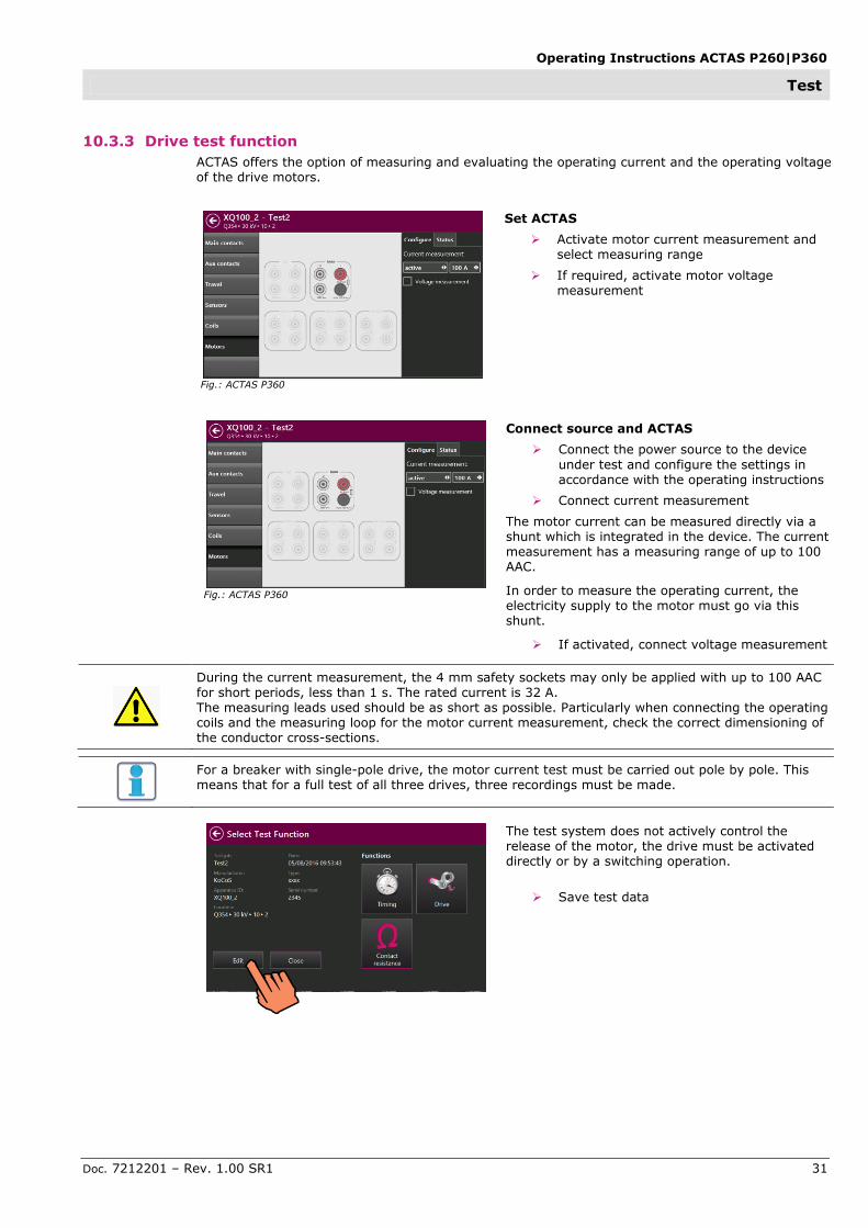
10.3.3 Drive test function
ACTAS offers the option of measuring and evaluating the operating current and the operating voltage of the drive motors.
Fig.: ACTAS P360
Set ACTAS
Activate motor current measurement and select measuring range
If required, activate motor voltage measurement
Fig.: ACTAS P360
Connect source and ACTAS
Connect the power source to the device
under test and configure the settings in accordance with the operating instructions
Connect current measurement
The motor current can be measured directly via a shunt which is integrated in the device. The current measurement has a measuring range of up to 100 AAC.
In order to measure the operating current, the electricity supply to the motor must go via this shunt.
If activated, connect voltage measurement
During the current measurement, the 4 mm safety sockets may only be applied with up to 100 AAC for short periods, less than 1 s. The rated current is 32 A. The measuring leads used should be as short as possible. Particularly when connecting the operating coils and the measuring loop for the motor current measurement, check the correct dimensioning of the conductor cross-sections.
For a breaker with single-pole drive, the motor current test must be carried out pole by pole. This means that for a full test of all three drives, three recordings must be made.
The test system does not actively control the release of the motor, the drive must be activated directly or by a switching operation.
Save test data

Operating Instructions ACTAS P260|P360
Test
Doc. 7212201 – Rev. 1.00 SR1 32
Complete test job
Close test job
Save test job data
The designation, apparatus ID and the serial number are required fields.

Operating Instructions ACTAS P260|P360
Analyse tests
Doc. 7212201 – Rev. 1.00 SR1 33
11 Analyse tests
Completed test jobs which are saved in the test
system can be opened and analysed.
11.1 Select tests
The jobs saved in the test system can be displayed
in a sortable list. It is also possible to search for the test jobs of a specific switchgear device. Recently completed jobs are displayed directly under Recently used and can be opened with a single tap.
Under All, all the tests carried out in the test job can be opened. Using the arrow keys it is easy to browse through all the tests.
Under Operation, individual tests can be selected for opening

Operating Instructions ACTAS P260|P360
Analyse tests
Doc. 7212201 – Rev. 1.00 SR1 34
11.2 Result display
The results obtained are shown on the right-hand
side of the display. Using the arrow keys it is easy to browse through all the tests.
11.2.1 Delete and export recordings
Recordings can be evaluated, deleted or exported under Data/Graph.
Under Export, test data or test reports can be saved on a USB flash drive.
The data can also be displayed in list form. A large amount of data can be exported at once by making multiple selections.

Operating Instructions ACTAS P260|P360
Analyse tests
Doc. 7212201 – Rev. 1.00 SR1 35
11.2.2 Change parameters for evaluation
The settings for calculating the results such as close-open speed, coil current and motor current can be edited later on. For more information, see the sections of these operating instructions titled Configure switchgear device/Evaluation. If values are edited here, the results are recalculated.
11.2.3 Help functions for evaluation
A wide range of views and functions for evaluating tests are available under Analyse
An evaluation band is shown in the Metric view. If the arrow buttons are used to move the band, it jumps automatically from one binary change to the
next so that the results in these areas are displayed.
The time values within the band are displayed in the Timing view. In addition, the view can also be changed using a zoom, for example. The scale and the size can also be changed. Individual signals can be displayed in a stack for the purpose of better evaluation and comparison. It is also possible to show and hide individual phases and signals.

Operating Instructions ACTAS P260|P360
Analyse tests
Doc. 7212201 – Rev. 1.00 SR1 36
By tapping an individual signal, the signal is selected and the results for this signal are shown separately.
The results displayed and the evaluation of results are explained in the result help.
By changing from Auto mode into Manual mode, the results can be evaluated with a cursor. A main and a delta cursor are provided for this purpose.

Operating Instructions ACTAS P260|P360
Analyse tests
Doc. 7212201 – Rev. 1.00 SR1 37
12 Maintenance and service
Before any maintenance or service work is carried out, the system and the connection to the
power supply must be interrupted!
12.1 Cleaning
Only use a dry linen cloth to clean the test system. If it is very dirty, the cloth may be dampened slightly.
Do not use any cleaning agents which contain solvents for cleaning.
Do not allow any moisture to get inside the test system.
12.2 Servicing
Repairs may only be carried out by authorized personnel after consultation with KoCoS Messtechnik AG and only using original spare parts.
12.3 Calibration
Changes in the amplification and/or offset of the measurement inputs and control outputs may take place over time as the components of the test instrument age.
Regular calibration is necessary in order to ensure that the test system functions correctly. We recommend that the test system be calibrated every two years and, if necessary, adjusted!
Calibration can either be carried out in the KoCoS Messtechnik AG calibration laboratory or on site using the calibration tool contained in the software. More detailed information on the calibration tool can be found in the separate user manual for the testing software.
Please note that the accuracy of the calibration depends on the accuracy of the measuring
devices which are used. If the necessary measuring devices are not available, the device should be calibrated by the manufacturer.
The adjustment of the test instrument is software controlled and is described in the separate user manual for the testing software.

Operating Instructions ACTAS P260|P360
Analyse tests
Doc. 7212201 – Rev. 1.00 SR1 38
13 Guarantee conditions
KoCoS Messtechnik AG guarantees that this product will function correctly for two years from the
date of the invoice. During this period defective devices are repaired free of charge; alternatively, defective devices, or certain components of such devices, are replaced.
If a defect occurs, the device can be sent in for repair after consultation with the service department of KoCoS Messtechnik AG. For devices which have been repaired, the guarantee is still valid for the rest of the remaining guarantee period and for at least 90 days after the repair for those parts affected by the repair.
This guarantee does not cover:
Defects resulting from unauthorized modifications or attempts to make repairs carried out by persons not authorized to do so.
Defects arising from improper use, e.g. through overvoltage
Mechanical damage caused by external influences
Fuses and other materials subject to wear
No guarantee is undertaken for the suitability of ACTAS P260|360 for a specific application.
KoCoS Messtechnik AG is not liable for indirect, direct, especial or consequential damage stemming from the use of this product.
13.1 Calibration confirmation
This device has been tested and calibrated in accordance with the published technical data.
Calibration is carried out using measuring instruments which are compared and set in accordance with certified measurement standards at regular and suitable intervals.

Operating Instructions ACTAS P260|P360
Technical data
Doc. 7212201 – Rev. 1.00 SR1 39
14 Technical data
14.1.1 Control outputs Electronic switching outputs (IGBT) for single or three-phase control of the closing and opening coils. All operating sequences can be configured and output in increments of 1 ms.
IGBTs for controlling the release coils
Voltage 300 VAC/DC Intrinsically safe via short-circuit and overload protection
Current 15/100 AAC/DC
14.1.2 Measurement inputs 14.1.2.1.1 General
Record length max. 4000 s
14.1.2.1.2 A/D-conversion 16 bit
Accuracy Error (< 0.05%)
14.1.2.1.3 Analog inputs Sampling rates 100 Hz...30 kHz, adjustable
14.1.2.1.4 Close/Open coil current 15/100 AAC/DC internally switchable
14.1.2.1.5 Coil/station voltage 300 VAC/DC
14.1.2.1.6 Motor voltage 500 VAC/DC
14.1.2.1.7 Motor current 15/100 AAC/DC
Sensor inputs 10 VDC/digital
Sensor inputs 0-20 mA/Imp. 200 Ohm/
0.25 W/ 10 VDC
Binary inputs Sampling rate auxiliary contact Activation level
10.00 kHz 24...300 VDC wet/dry switching
Incremental inputs for digital travel transducers
Supply voltage 10 VDC
Limit frequency 100 kHz
Interfaces KoCoS interfaces Interfaces for controlling external ohm meters and a connection unit CSW3 as well as a source for the power supply for testing undervoltage and overvoltage releases
PC interfaces RJ45 Ethernet USB A/B
Complete system
Operation Operation, system control, data storage and evaluation by means of a built-in control panel equipped with a high-resolution, resistive 7" touch screen and two function keys
Data storage and evaluation of switchgear tests also by means of an external PC under Windows 7/8.1/10
Optional Wi-Fi remote function
Power supply Rated voltage 110...265 VAC/DC
Environment Operating temperature Electric strength EMC immunity Protection Safety standard EMC emissions Susceptibility
0...50 °C to IEC 255/IEC 801 1 MHz sine wave to IEC 255 IP65 (closed) EN 61010-1 300 V~ CAT II EN 50081-2 industrial EN 50082-2 industrial

Operating Instructions ACTAS P260|P360
Technical data
Doc. 7212201 – Rev. 1.00 SR1 40
Product specifications
ACTAS P260 ACTAS P360
Analog measurement inputs Coil current 1 x 2 (I/O) 3 x 2 (I/O)
Coil/station voltage - 2
Motor current via shunt 1 1
Motor voltage 1 1
Sensor (+/-10 V/digital) 3 6
Sensor (+/-10 V/0…20 mA) 1 3
Main and PIR contacts 3 x 2 6 x 2
Binary measurement inputs Auxiliary contacts 2 x 4 3 x 4
Control outputs Closing coils 1 3
Opening coils 1 3
Analog outputs Reference voltage for
external sensors
1x 10 VDC/200 mA 3x 10 VDC/200 mA
Connections additional equipment
PC Ohm meter
CSW3 Digital voltage source
1 3 1 1
1 3 1 1
Housing Hard-top case
Dimensions (W x H x D) 425 x 340 x 170 475 x 375 x 180
Weight 5.3 kg 6.9 kg