Switchgear RVAC Fuses
13
Contents General . . . . . . . . . . . . . . . . . . . . . .1 Installation . . . . . . . . . . . . . . . . . . .1 Produ ction T ests . . . . . . . . . . . . . .1 Elect rical C haract erist ics . . . . . . .3 Dimensions and We ights . . . . . . .4 15 kV Switchgear . . . . . . . . . . . .4 25 kV and 35 kV Switchgear . . .6 Application . . . . . . . . . . . . . . . . . . .8 Ordering Information . . . . . . . . . .10 15 kV Switchgear . . . . . . . . . . .10 25 kV and 35 kV Switchgear . .11 Additional Information . . . . . . . . .12 GENERAL The Cooper Power Systems RTE ® ELSG full range current-limiting fuse is designed for use in padmount switchgear filled with mineral oil or approved equivalent. It may also be used to protect power transformers, feeders and other equipment that can benefit from its energy-limiting proper- ties. The fuse provides consistent clearing of low currents as well as reliable high speed interruption of high magnitude short circuit currents. Its current-limiting capability limits both peak current magnitude and fault duration, thus limiting the let-through energy. ELSG fuses have both the low current and high current clearing sections in one housing. This eliminates expulsion byproducts discharging into the oil when the fuse operates. Concerns associated with miscoordination of separate expulsion and current-limiting fuse sections in the field are eliminated. Also, field testing the current-limiting section when the expulsion section operates is also eliminated. The E-rated ELSG fuses have time- current characteristics that coordinate easily with other upstream and down- stream protective devices. The MSLE version of the ELSG fuses are i nter- changeable with the K-MATE™ SL (A.B. Chanc e) assembly. ELSG f uses have been tested and meet all requirements set forth in ANSI/IEEE C37.40, C37.41, and C37.46 Standards. INSTALLATION No special tools are required. The ELSG fuse assembly is lowered into the wetwell holder (see Catalog Section 240-83) of de-energized apparatus using a shotgun stick. The ELSG fuses are shipped as complete assemblies ready to install. No adapters are needed with the Cooper Power Systems fuses. Refer to Installation Instruction Sheet S240-82-1 for details. PRODUCTION TESTS Tests are conducted in accordance with Cooper Power Systems requirements. ■ Physical Inspection ■ I 2 t Testing ■ Resistance Testing ■ Helium Mass Spectrometer Leak Testing Fusing Equipment ELSG Full Range Current-Limiting Fuse Electrical Apparatus 240-82 1 July 1999 • Supercedes 9/93 Printed in U.S.A. TABLE 1 Maximum Interrupting Current (rms symmetrical) 8.3 kV 15.5 kV 23 kV ELSG E-Rated 50,000 A 50,000 A 50,000 A 20,000 A (65E–150E for 12,200 A (50E-100E) M83M series; 120E & 150E for M01M series) ELSG MSLE Version 31,000 A 20,000 A 12,200 A Figure 1. ELSG Current-Limiting fuses. Single 2" Diameter Fuse Single 3" Diameter Fuse Double-Barrel Fuse Assembly Triple-Barrel Assembly Fuse
-
Upload
luis-murillo -
Category
Documents
-
view
216 -
download
0
Transcript of Switchgear RVAC Fuses

8/22/2019 Switchgear RVAC Fuses
http://slidepdf.com/reader/full/switchgear-rvac-fuses 1/12
ContentsGeneral . . . . . . . . . . . . . . . . . . . . . .1Installation . . . . . . . . . . . . . . . . . . .1Production Tests . . . . . . . . . . . . . .1
Electrical Characteristics . . . . . . .3Dimensions and Weights . . . . . . .4
15 kV Switchgear . . . . . . . . . . . .425 kV and 35 kV Switchgear . . .6
Application . . . . . . . . . . . . . . . . . . .8Ordering Information . . . . . . . . . .10
15 kV Switchgear . . . . . . . . . . .10
25 kV and 35 kV Switchgear . .11Additional Information . . . . . . . . .12
GENERAL
The Cooper Power Systems RTE ®
ELSG full range current-limiting fuseis designed for use in padmountswitchgear filled with mineral oil orapproved equivalent. It may also beused to protect power transformers,feeders and other equipment that canbenefit from its energy-limiting proper-ties. The fuse provides consistentclearing of low currents as well asreliable high speed interruption ofhigh magnitude short circuit currents.Its current-limiting capability limitsboth peak current magnitude and faultduration, thus limiting the let-throughenergy.
ELSG fuses have both the low currentand high current clearing sections inone housing. This eliminates expulsionbyproducts discharging into the oilwhen the fuse operates. Concernsassociated with miscoordination ofseparate expulsion and current-limitingfuse sections in the field are eliminated.Also, field testing the current-limitingsection when the expulsion sectionoperates is also eliminated.
The E-rated ELSG fuses have time-current characteristics that coordinateeasily with other upstream and down-stream protective devices. The MSLEversion of the ELSG fuses are inter-changeable with the K-MATE™ SL(A.B. Chance) assembly. ELSG fuseshave been tested and meet allrequirements set forth in ANSI/IEEEC37.40, C37.41, and C37.46Standards.
INSTALLATION
No special tools are required. TheELSG fuse assembly is lowered intothe wetwell holder (see CatalogSection 240-83) of de-energizedapparatus using a shotgun stick.
The ELSG fuses are shipped ascomplete assemblies ready to install.No adapters are needed with theCooper Power Systems fuses. Refer toInstallation Instruction Sheet S240-82-1for details.
PRODUCTION TESTS
Tests are conducted in accordancewith Cooper Power Systemsrequirements.
■ Physical Inspection■ I2t Testing■ Resistance Testing■ Helium Mass Spectrometer Leak
Testing
Fusing Equipment
ELSG Full Range Current-Limiting Fuse
Electrical Apparatu
240-82
July 1999 • Supercedes 9/93Printed in U.S.A.
TABLE 1Maximum Interrupting Current (rms symmetrical)
8.3 kV 15.5 kV 23 kV
ELSG E-Rated 50,000 A 50,000 A 50,000 A20,000 A (65E–150E for 12,200 A (50E-100EM83M series; 120E &
150E for M01M series)
ELSG MSLE Version 31,000 A 20,000 A 12,200 A
Figure 1.ELSG Current-Limiting fuses.
Single 2" Diameter Fuse Single 3" Diameter Fuse
Double-Barrel Fuse Assembly Triple-Barrel Assembly Fuse

8/22/2019 Switchgear RVAC Fuses
http://slidepdf.com/reader/full/switchgear-rvac-fuses 2/12
ELSG Full Range Current-Limiting Fuse
2
Figure 2.Cutaway illustration of the ELSG fuse.
MICA SPIDERProvides stable windingsupport without generatinggas and pressure build-upduring fuse operation.
HIGH PURITY SILICA SANDFILLERWith specific particle size,purity, and compaction givesthe heat-absorbing and arcquenching properties neces-sary for consistent clearingand low energy let-thru levels.
LOWER CONTACTThis contact supplied with thefuse provides an electricalconnection with the lowercontact of the wetwell ELSGholder.
FIBERGLASS HOUSINGProvides strength and maintains integrity
of fuse during any interruption, fromminimum melt current to maximum ratedinterrupting current.
LOW-CURRENT CLEARINGSECTIONProvides consistent reliableclearing of all currents highenough to melt the elementwithout auxiliary devices orelements.
INDELIBLE IDENTIFICATIONLABELIncludes easy-to-read voltageand current ratings and catalog
numbers.
DOUBLE SEALING SYSTEMWith Buna-N rubber gasketand epoxy sealant ensuresseal performance and integrity.
PURE SILVER ELEMENTIs stable under current cycling andthermal stress, providing consistentmelt characteristics. The punch-holeribbons effectively control and minimizepeak arc voltage levels resulting fromhigh current interruption. The elementeffectively controls and limits bothcurrent and energy I2t let-thru level.
Fuse Rating 8.3 kV 15.5 kVa
Continuous Minimum Maximum Minimum MaximumANSI Current Melt I2t Let-through I2t Melt I2t Let-through I2t
E-Rating Rating (A2 • s) (A2 • s) (A2 • s) (A2 • s)
4 9 820 5,000 820 5,000
8 14 820 5,000 820 5,000
12 18 1,460 9,800 1,460 9,800
15 24 2,280 13,800 2,280 13,800
20 34 2,280 13,800 2,280 13,800
25 35 3,280 27,300 3,280 27,300
30 46 9,110 53,400 9,110 56,600
40 53 9,110 53,400 9,110 56,600
50 65 13,120 69,200 13,120 75,000
50 96 –– –– –– ––
60 76 17,860 96,700 17,860 80,000
65 92 — — 36,440 115,000
65 95 18,000 72,000 –– ––
80 106 — — 36,440 115,000
80 125 40,000 130,000 — —
100 130 — — 52,480 300,000
100 155 72,000 220,000 –– ––120 150 –– –– 72,000 320,000
125 180 111,000 420,000 –– ––
150 200 –– –– 118,000 440,000
MSLE Version
N/A 50 9,000 53,000 –– ––
N/A 90 36,000 212,000 –– ––
Note: a These ratings are the 15.5 kV, M83M fuse series for the 15 kV wetwell holder.
TABLE 2ELSG Fuse Electrical Characteristics for 15 kV Wetwell Holders

8/22/2019 Switchgear RVAC Fuses
http://slidepdf.com/reader/full/switchgear-rvac-fuses 3/12
240-8
TABLE 3ELSG Time Current Characteristic (TCC) Curves
Voltage (kV) TCC Curve Number Fuse Design
8.3 R240-91-85 2" Dia. E-Rated (4E through 60E)8.3 R240-91-86 3" Dia. E-Rated (65E through 125E)8.3 R240-91-88 MSLE Version (50 & 90 A)
15.5 R240-91-85 2" Dia. E-Rated (4E through 150E for the 15 kV,M83M Series) and (4E through 60E, 120E & 150Efor the 15 kV, M02M Series)
15.5 R240-91-86 3" Dia. E-Rated (65E through 100E)15.5 R240-91-88 MSLE Version (50 & 90 A)
23 R240-91-89 2" Dia. E-Rated (4E through 100E)23 R240-91-88 MSLE Version (50, 90 & 135 A)
23 (long)* R240-91-87 E-Rated (40E through 125E)Single barrel – 3" Diameter
* This special 23 kV ELSG fuse is extra long to fit into the long 35 kV class wetwell holder (P/N 3437322C06MConsult factory for fuse catalog numbers.
TABLE 4MLSE Version ELSG Fuse Cross Reference*
Single-phase Cooper Power System A.B. ChanceMaximum Voltage MSLE Version ELSG Fuse K-MATE SL Assembly
Rating (kV) Catalog Number Catalog Number
8.3* 3593050MSLE C705-0254 (SL-54)3593090MSLE C705-0255 (SL-90)
15.5** 3594050MSLE C705-0443 (SL-54)3594090MSLE C705-0445 (SL-90)
23** 3595050MSLE C705-0450 (SL-54)3595090MSLE C705-0452 (SL-90)3595135MSLE ––
* Fuses are mechanically interchangeable and can typically be used for the same application** Fuses are both electrically and mechanically interchangeable.
Figure 3.100E rated current-limiting fuse “gate” per ANSI.
1 0 0
1 0
1 0 0 0
1 0 , 0 0 0
1 0 0 , 0 0 0
1000
300
100
10
1
.1
.01
T I M E I N
S E C O N D S
CURRENT IN AMPERES
MINIMUM MELTING TCCAT 300 SECONDS200% TO 240% OFFUSE RATING
100E FUSE 1 100E FUSE 2
ANSI C37.46 "GATE"
ELECTRICALCHARACTERISTICS
The ELSG fuses are given an “E” ratedcharacteristic, which is described inANSI/IEEE C37.46 standard. The “E”rating defines a Time CurrentCharacteristic (TCC) curve reference“gate” for power fuse rating standard-
ization:E rating “gates”: per ANSI C37.46
0-100E @ 300 sec, 200-240% ofmelting current or percent rating.
125E-200E @ 600 sec, 220-264%of melting current or percent rating.
Figure 3 shows an example of twodifferent “100E” fuse TCC curves.Both meet ANSI requirements for the100E rating. The “E” rating does notdefine the continuous current ratingallowable by the fuse and should notbe used as the only characteristic to
establish interchangeability with other“E” rated fuses.
To further provide operating perfor-mance characteristics, the ELSG fusesare tested to determine a continuouscurrent rating. The continuous currentrating is specified as being the maxi-mum current the fuse can carrycontinuously without exceeding thetemperature rises detailed in theANSI/IEEE standards.
The electrical characteristics for theELSG fuses that mount in the 15 kVwetwell holder are described in Table 2.Table 5 details the electrical charac-teristics for the ELSG fuses for the 25and 35 kV wetwell holder.
The ELSG fuses are also available inthe MSLE version. These fuses aredesigned as a continuous currentrated fuse to meet the electricaland/or mechanical characteristics ofthe AB Chance K-Mate fuses. Table 4shows the cross reference betweenthe ELSG MSLE version fuses andthe AB Chance K-Mate SL fuses.
The TCC curves for ELSG E-ratedand MSLE version fuses are shown inTable 3.

8/22/2019 Switchgear RVAC Fuses
http://slidepdf.com/reader/full/switchgear-rvac-fuses 4/12
ELSG Full Range Current-Limiting Fuse
4
TABLE 6ELSG E-Rated Fuse Dimensional Information* for 15 kV Wetwell Holders
Fuse Rating Dimensions
Voltage ANSIinches (mm)
Weight Figure Number(kV) E-Rating A lbs. (kg) Reference
8.3 4-60E 8.4 (213) 2.9 (1.3) 48.3 65-125E 16.0 (406) 9.0 (4.0) 5
15.5 4-60E 12.8 (325) 2.9 (1.3) 415.5 65-120E 12.8 (325) 12.2 (5.5) 615.5 150E 12.8 (325) 12.2 (5.5) 7
TABLE 7MSLE Version ELSG Fuse Dimensional Information* for 15 kV Wetwell Holders
Fuse Rating Dimensionsinches (mm)
Voltage Continuous Weight Figure Number(kV) Current (A) A lbs. (kg) Reference
8.3 50 8.4 (213) 2.9 (1.3) 48.3 90 8.4 (213) 6.0 (2.7) 6
DIMENSIONS AND WEIGHTS
15 kV Switchgear
Fuse Rating 15.5 kV 23.0 kV
Continuous Minimum Maximum Minimum MaximumANSI Current Melt I2t Let-through I2t Melt I2t Let-through I2t
E-Rating Rating (A2 • s) (A2 • s) (A2 • s) (A2 • s)
4 9 820 5,000 820 5,000
8 14 820 5,000 820 5,000
12 18 1,460 9,800 1,460 9,80015 24 2,280 13,800 2,280 13,800
20 34 2,280 13,800 2,280 13,800
25 35 3,280 27,300 3,280 27,300
30 46 9,110 56,600 9,110 59,000
40 53 9,110 56,600 9,110 59,000
50 65 13,120 75,000 –– ––
50 96 –– –– 36,000 212,000
60 76 17,860 80,000 –– ––
65 95 18,000 125,000 –– ––
65 120 –– –– 36,000 212,000
80 125 40,000 185,000 — —
80 145 — — 82,000 394,000
100 140 72,000 305,000 — —
100 180 — — 82,000 394,000
120 150 72,000 320,000 –– ––150 200 118,000 440,000 –– ––
MSLE Version
N/A 50 9,000 53,000 9,000 53,000
N/A 90 36,000 212,000 36,000 212,000
N/A 135 –– –– 82,000 394,000
TABLE 5ELSG Fuse Electrical Characteristics for 25 & 35 kV Wetwell Holder
* Refer to Figures 4, 5, 6 and 7 for dimensional drawings.
* Refer to Figures 4 and 6 for dimensional drawings.

8/22/2019 Switchgear RVAC Fuses
http://slidepdf.com/reader/full/switchgear-rvac-fuses 5/12
240-8
Figure 6.Dimensional information for E-rated 15.5 kV (65E-120E) and 15.5 kV (90 A) MSLE version ELSG fuses.
Note: Dimensions are given in Table 6 and Table 7.
2.155"(54.74 mm)
1.0"(25.4 mm)
4.30"(109.2 mm)
2.33"(59.2 mm)
LOWER CONTACT
4.37"(111 mm)
1.53"(38.9 mm)
3/8" - 16 THREAD x .5 FULL THREAD DEPTH
.722"(18.3 mm)
A
19.2" (488 mm)
Figure 5.Dimensional information for E-rated 8.3 kV (65E-125E) version ELSG fuses.
Note: Dimensions are given in Table 6.
3/8"-16 THREAD
1.85"(46.99 mm)
A
19.2" (488 mm)
3.25"(82.6 mm)
3.00"(76.2 mm) LOWER
CONTACT
1.00"(25.4 mm)
Figure 4.Dimensional information for single 2" diameter 8.3 kV and 15 kV E-rated and MSLE version ELSG fuses.
Note: Dimensions are given in Tables 6 and 7.
.625"(15.9 mm)
A
19.2" (488 mm)
2.33"(59.2 mm)
LOWER CONTACT
2.155"
(54.74 mm
1.00"(25.4 mm)
3/8"-16 THREADx .5 FULL
THREAD DEPTH

8/22/2019 Switchgear RVAC Fuses
http://slidepdf.com/reader/full/switchgear-rvac-fuses 6/12
ELSG Full Range Current-Limiting Fuse
6
Figure 7.Dimensional information for E-rated 15.5 kV (150E) version ELSG fuses.
Note: Dimensions are given in Table 6.
3.30"(83.82 mm)
3/8"-16THD THRU
1.20"(30.48 mm)
.30"(7.62 mm)
1.23"(31.24 mm)
2.17"(55.12 mm)
2.17"(55.12 mm)
A
19.2" (488 mm)
4.68"(118.9 mm)
TRIPLE FUSE ASSEMBLY
2.33"(59.2 mm) 1.00"
(25.40 mm)
4.00"(101.6 mm)
LOWERCONTACT
DELRIN GUIDE ROD –USED AS A MECHANICAL
GUIDE FOR EASIER
INSTALLATION
TABLE 8
ELSG E-Rated Fuse Dimensional Information* for 25 & 35 kV Wetwell Holder
Fuse Rating Dimensions
Voltage ANSIinches (mm)
Weight Figure Number(kV) E-Rating A lbs. (kg) Reference
15.5 4-60E 12.8 (325) 3.8 (1.7) 815.5 65-100E 19.0 (483) 10.2 (4.7) 915.5 120E 12.8 (325) 12.2 (5.5) 1015.5 150E 12.8 (325) 12.2 (5.5) 11
23.0 4-40E 15.6 (539) 4.4 (2.0) 823.0 50-65E 15.6 (539) 9.1 (4.1) 1023.0 80-100E 15.6 (539) 14.0 (6.3) 12
TABLE 9MSLE Version ELSG Fuse Dimensional Information* for 25 & 35 kV Wetwell Holder
Fuse Rating Dimensions
Voltage Continuousinches (mm)
Weight Figure Number(kV) Current (A) A lbs. (kg) Reference
15.5 50 12.7 (323) 3.8 (1.7) 815.5 90 12.7 (323) 7.8 (3.5) 10
23.0 50 15.6 (396) 4.4 (2.0) 823.0 90 15.6 (396) 9.1 (4.1) 1023.0 135 15.6 (396) 14.0 (6.3) 12
DIMENSIONS AND WEIGHTS
25 and 35 kV Switchgear
* Refer to Figures 8, 9, 10, 11 and 12 for dimensional drawings.
* Refer to Figures 8, 10 and 12 for dimensional drawings.

8/22/2019 Switchgear RVAC Fuses
http://slidepdf.com/reader/full/switchgear-rvac-fuses 7/12
240-8
Figure 10.Dimensional information for E-rated 15.5 kV (120E) and 23 kV (50E, 65E) and 15.5 kV and 23 kV (90A) MSLE version ELSGfuses.
Note: Dimensions are given in Table 8 and Table 9.
2.155"(54.74 mm)
1.0"(25.4 mm)
4.30"(109.2 mm)
2.33"(59.2 mm)
LOWER CONTACT
4.37"(111 mm)
1.53"(38.9 mm)
3/8"-16 THREAD x .5 FULL THREAD DEPTH
.722"(18.3 mm)
A
21.2" (539 mm)
Figure 9.Dimensional information for E-rated 15.5 kV (65E-100E) version ELSG fuses.
Note: Dimensions are given in Table 8.
3/8"-16 THREAD
1.85"(46.99 mm)
A
21.2" (539 mm)
3.25"(82.6 mm)
3.00"(76.2 mm) LOWER
CONTACT
1.00"(25.4 mm
Figure 8.Dimensional information for single 2" diameter 15 kV and 23 kV E-rated and MSLE version ELSG fuses.
Note: Dimensions are given in Tables 8 and 9.
.625"(15.9 mm)
A
21.2" (539 mm)
2.33"(59.2 mm)
LOWER CONTACT
2.155"(54.74 mm
1.00"(25.4 mm)
3/8"-16 THREADx .5 FULL
THREAD DEPTH

8/22/2019 Switchgear RVAC Fuses
http://slidepdf.com/reader/full/switchgear-rvac-fuses 8/128
APPLICATION
Method A
USING THE CORRELATION
TABLES
Use Table 10 to determine the amper-age and voltage ratings of the E-ratedELSG fuse required for the application.Use Table 11 to determine theamperage and voltage ratings of the
MSLE version ELSG fuses requiredfor the application. In the orderinginformation section, the fuse selectionguides (Figures 13-15) can be usedto determine applicable fuse catalognumber.
Method B
USING TIME CURRENT CURVES
To determine or confirm the ELSG fusethat will coordinate with upstream anddownstream system requirements,use the time-current characteristiccurves and specify the fuse indicatedfrom Tables 12-15. For full size TCCcurves, or other applications, contactyour Cooper representative.
ELSG Full Range Current-Limiting Fuse
Figure 11.Dimensional information for E-rated 15.5 kV (150E) version ELSG fuses.
Note: Dimensions are given in Table 8.
3.30"(83.82 mm)
3/8"-16THD THRU
1.20"(30.48 mm)
.30"(7.62 mm)
1.23"(31.24 mm)
2.17"(55.12 mm)
2.17"(55.12 mm)
A
21.2" (539 mm)
4.68"(118.9 mm)
TRIPLE FUSE ASSEMBLY
2.33"
(59.2 mm) 1.00"(25.40 mm)
4.00"(101.6 mm)
LOWERCONTACT
DELRIN GUIDE ROD –USED AS A MECHANICAL
GUIDE FOR EASIERINSTALLATION
Figure 12.Dimensional information E-rated 23 kV (80E, 100E) and MSLE 23 kV (135A) version ELSG fuses.
Note: Dimensions are given in Tables 8 and 9.
3.30"(83.82 mm)
3/8"-16THD THRU
1.20"(30.48 mm)
.30"(7.62 mm)
1.23"(31.24 mm)
2.17"(55.12 mm)
2.17"(55.12 mm) 3.38"
(85.85 mm)
A
21.2" (539 mm)
1.00"(25.40 mm)
4.00"(101.6 mm)
LOWER
CONTACT
DELRIN GUIDE ROD –USED AS A MECHANICAL
GUIDE FOR EASIERINSTALLATION
4.68"(118.9 mm)
TRIPLE FUSE ASSEMBLY
8/22/2019 Switchgear RVAC Fuses
http://slidepdf.com/reader/full/switchgear-rvac-fuses 9/12
240-8
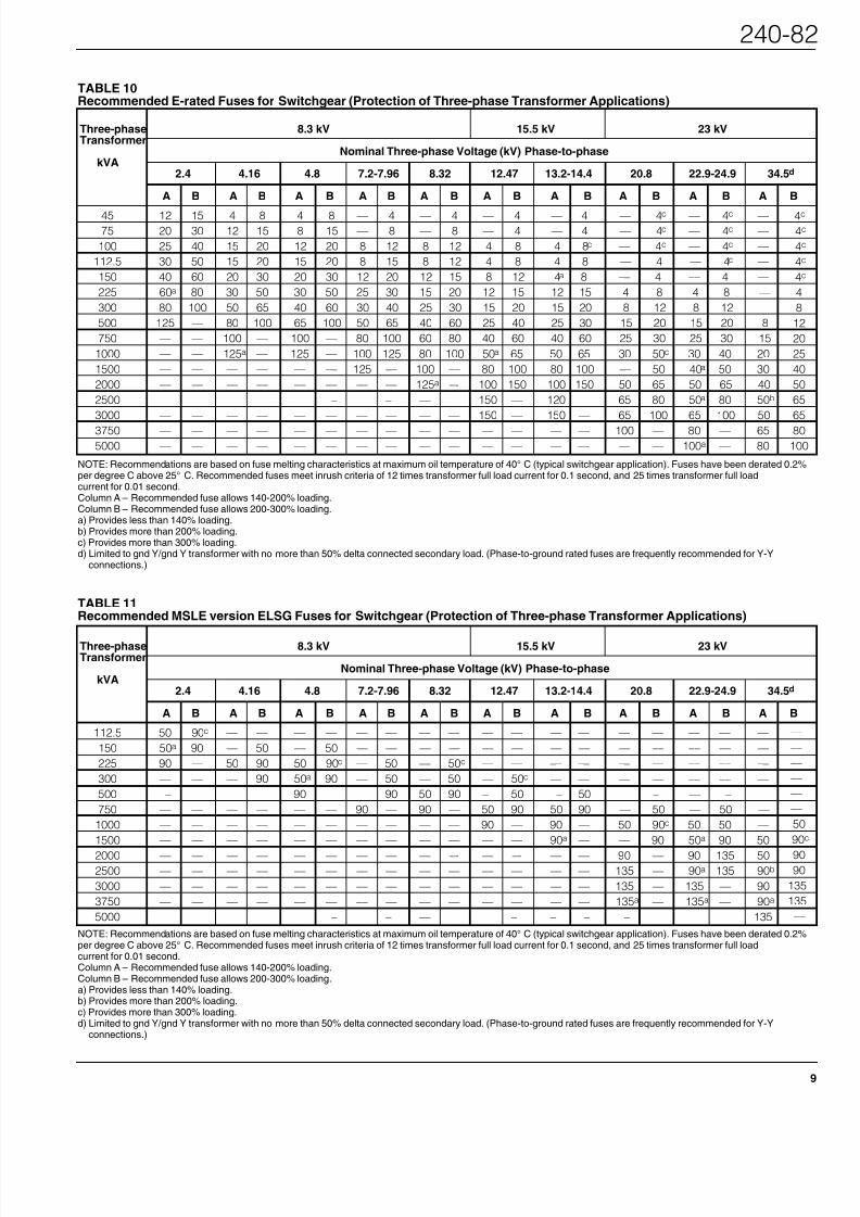
TABLE 11Recommended MSLE version ELSG Fuses for Switchgear (Protection of Three-phase Transformer Applications)
Three-phase 8.3 kV 15.5 kV 23 kVTransformer
Nominal Three-phase Voltage (kV) Phase-to-phasekVA
2.4 4.16 4.8 7.2-7.96 8.32 12.47 13.2-14.4 20.8 22.9-24.9 34.5d
A B A B A B A B A B A B A B A B A B A B
112.5 50 90c –– –– –– –– –– –– –– –– –– –– –– –– –– –– –– –– ––
150 50a 90 –– 50 –– 50 –– –– –– –– –– –– –– –– –– –– –– –– ––
225 90 –– 50 90 50 90c –– 50 –– 50c –– –– –– –– –– –– –– –– ––
300 –– –– –– 90 50a 90 –– 50 –– 50 –– 50c –– –– –– –– –– –– ––
500 –– –– –– –– 90 –– –– 90 50 90 –– 50 –– 50 –– –– –– –– ––
750 –– –– –– –– –– –– 90 –– 90 –– 50 90 50 90 –– 50 –– 50 ––
1000 –– –– –– –– –– –– –– –– –– –– 90 –– 90 –– 50 90c 50 50 ––
1500 –– –– –– –– –– –– –– –– –– –– –– –– 90a –– –– 90 50a 90 50
2000 –– –– –– –– –– –– –– –– –– –- –– –- –– –– 90 –– 90 135 502500 –– –– –– –– –– –– –– –– –– –– –– –– –– –– 135 –– 90a 135 90b
3000 –– –– –– –– –– –– –– –– –– –– –– –– –– –– 135 –– 135 –– 90
3750 –– –– –– –– –– –– –– –– –– –– –– –– –– –– 135a –– 135a –– 90a
5000 –– –– –– –– –– –– –– –– –– –– –– –– –– –– –– –– –– –– 135
––
––
––
––
––
––
50
90
9090
135
135
––
NOTE: Recommendations are based on fuse melting characteristics at maximum oil temperature of 40° C (typical switchgear application). Fuses have been derated 0.2%per degree C above 25° C. Recommended fuses meet inrush criteria of 12 times transformer full load current for 0.1 second, and 25 times transformer full loadcurrent for 0.01 second.Column A – Recommended fuse allows 140-200% loading.Column B – Recommended fuse allows 200-300% loading.a) Provides less than 140% loading.b) Provides more than 200% loading.c) Provides more than 300% loading.d) Limited to gnd Y/gnd Y transformer with no more than 50% delta connected secondary load. (Phase-to-ground rated fuses are frequently recommended for Y-Y
connections.)
TABLE 10Recommended E-rated Fuses for Switchgear (Protection of Three-phase Transformer Applications)
Three-phase 8.3 kV 15.5 kV 23 kVTransformer
Nominal Three-phase Voltage (kV) Phase-to-phasekVA
2.4 4.16 4.8 7.2-7.96 8.32 12.47 13.2-14.4 20.8 22.9-24.9 34.5d
A B A B A B A B A B A B A B A B A B A B
45 12 15 4 8 4 8 –– 4 –– 4 –– 4 –– 4 –– 4c –– 4c ––75 20 30 12 15 8 15 –– 8 –– 8 –– 4 –– 4 –– 4c –– 4c ––
100 25 40 15 20 12 20 8 12 8 12 4 8 4 8c –– 4c –– 4c ––
112.5 30 50 15 20 15 20 8 15 8 12 4 8 4 8 –– 4 –– 4c ––
150 40 60 20 30 20 30 12 20 12 15 8 12 4a 8 –– 4 –– 4 ––
225 60a 80 30 50 30 50 25 30 15 20 12 15 12 15 4 8 4 8 ––
300 80 100 50 65 40 60 30 40 25 30 15 20 15 20 8 12 8 12 ––
500 125 –– 80 100 65 100 50 65 40 60 25 40 25 30 15 20 15 20 8
750 –– –– 100 –– 100 — 80 100 60 80 40 60 40 60 25 30 25 30 15
1000 –– –– 125a –– 125 –– 100 125 80 100 50a 65 50 65 30 50c 30 40 20
1500 –– –– –– –– –– –– 125 –– 100 –– 80 100 80 100 –– 50 40a 50 30
2000 –– –– –– –– –– –– –– –– 125a –- 100 150 100 150 50 65 50 65 40
2500 –– –– –– –– –– –– –– –– –– –– 150 –– 120 –– 65 80 50a 80 50b
3000 –– –– –– –– –– –– –– –– –– –– 150 –– 150 –– 65 100 65 100 50
3750 –– –– –– –– –– –– –– –– –– –– –– –– –– –– 100 — 80 –– 65
5000 –– –– –– –– –– –– –– –– –– –– –– –– –– –– –– –– 100a –– 80
4c
4c
4c
4c
4c
4
8
12
20
25
40
50
65
65
80
100
NOTE: Recommendations are based on fuse melting characteristics at maximum oil temperature of 40° C (typical switchgear application). Fuses have been derated 0.2%per degree C above 25° C. Recommended fuses meet inrush criteria of 12 times transformer full load current for 0.1 second, and 25 times transformer full loadcurrent for 0.01 second.Column A – Recommended fuse allows 140-200% loading.Column B – Recommended fuse allows 200-300% loading.a) Provides less than 140% loading.b) Provides more than 200% loading.c) Provides more than 300% loading.d) Limited to gnd Y/gnd Y transformer with no more than 50% delta connected secondary load. (Phase-to-ground rated fuses are frequently recommended for Y-Y
connections.)

8/22/2019 Switchgear RVAC Fuses
http://slidepdf.com/reader/full/switchgear-rvac-fuses 10/1210
ORDERING INFORMATION
15 kV Switchgear
STEP 1
To order a Cooper Power SystemsE-rated ELSG current-limiting fuse,determine the appropriate voltageand current ratings from the
Application Section (refer to Table 10).
To order the MSLE version ELSG fuse,determine the appropriate voltage andcontinuous current ratings from theApplication Section (refer to Table 11)or specify the appropriate catalognumber in Table 4 by cross referenc-ing an equivalent A.B. ChanceSL fuse.
STEP 2
Use the appropriate Fuse SelectionGuide (refer to Figure 13) to find theapplicable ELSG catalog numbers.
STEP 3
Select the appropriate ELSG catalognumber from Tables 12 or 13.
TABLE 12E-rated ELSG Fuse Ordering Information for 15 kV Wetwell Holder*
Continuous Fuse kV and Catalog NumberE-Rating Current
Rating (A) 8.3 kV 15.5 kV
4 9 3593004M02M 3594004M83M8 14 3593008M02M 3594008M83M
12 18 3593012M02M 3594012M83M
15 24 3593015M02M 3594015M83M
20 34 3593020M02M 3594020M83M
25 35 3593025M02M 3594025M83M
30 46 3593030M02M 3594030M83M
40 53 3593040M02M 3594040M83M
50 65 3593050M02M 3594050M83M
60 76 3593060M02M 3594060M83M
65 92 — 3594065M83M
65 95 3593065M01M ––
80 106 — 3594080M83M
80 125 3593080M01M ––
100 130 — 3594100M83M100 155 3593100M01M ––
120 150 –– 3594120M83M
125 180 3593125M01M ––
150 200 –– 3594150M83M
* 15 kV Wetwell Holder part numbers 3437322C01M (mild steel) and 3437322C02M (stainless steel)
* 15 kV Wetwell Holder part numbers 3437322C01M (mild steel) and 3437322C02M (stainless steel)
Switchgear Rating 15 kV Classa
Wetwell Holder: 15 kV3437322C01M (mild steel)
3437322C02M (stainless steel)
Primary GrdY ∆ Y UnGrdY ∆
Secondary GrdY Y ∆ UnGrdY ∆
Wetwell Holder
Voltage Rating 15 kV 15 kV 15 kV 15 kV
Fuse VoltageRating 8.3 kVb 15.5 kV 15.5 kV 15.5 kV
TransformerConnection
Applicable 8.3 kV ELSG Fuse Cat. Nos:
3593004M02M through 3593060M02M
3593065M01M through 3593125M01M
3593050MSLE
3593090MSLE
(Refer to Tables 12 & 13)
Applicable 15.5 kV ELSG Fuse Cat. Nos:
3594004M83M through 3594150M83M
(Refer to Table 12)
Figure 13.Fuse Selection Guide for 15 kV Class Switchgear.
Notes:a The wetwell holder selections represent standard designs, special switchgear configurations may be
possible. Consult Cooper Power Systems Distribution Switchgear.b Limited to Grd Y/Grd Y transformer with no more than 50% Delta and/or UnGrd Y connected secondary
load.
TABLE 13MLSE Version ELSG Fuse Ordering Information for 15 kV Wetwell Holder*
Voltage Rating Continuous Current(kV) Rating (A) Catalog Number
8.3 50 3593050MSLE90 3593090MSLE
ELSG Full Range Current-Limiting Fuse

8/22/2019 Switchgear RVAC Fuses
http://slidepdf.com/reader/full/switchgear-rvac-fuses 11/12
Applicable 23 kV ELSG Fuse Cat. Nos:3595004M02M through 3595100M02M
3595050MSLE
3595090MSLE
3595135MSLE
(Refer to Table 14 & 15)
No Fuse Available
Applicable 15.5 kV ELSG Fuse Cat. Nos:
3594004M02M through 3594060M02M
3594065M01M through 3594100M01M
3594120M02M through 3594150M02M
3594050MSLE
3594090MSLE
(Refer to Tables 14 & 15)
Applicable 23 kV ELSG Fuse Cat. Nos:
3595004M02M through 3595100M02M
3595050MSLE
3595090MSLE
3595135MSLE
(Refer to Table 14 & 15)
Switchgear Rating 25 kV Classa
Wetwell Holder: 25/35 kV3437322C05M (mild steel)
3437322C07M (stainless steel)
Primary GrdY ∆ Y UnGrdY ∆
Secondary GrdY Y ∆ UnGrdY ∆
Wetwell Holder
Voltage Rating 25/35 kV 25/35 kV 25/35 kV 25/35 kV
Fuse VoltageRating 15 kVb 23 kV 23 kV 23 kV
TransformerConnection
Switchgear Rating 35 kV Classa
Wetwell Holder: 25/35 kV3437322C05M (mild steel)3437322C07M (stainless steel)
Primary GrdY ∆ Y UnGrdY ∆
Secondary GrdY Y ∆ UnGrdY ∆
Wetwell Holder
Voltage Rating 25/35 kV 25/35 kV 25/35 kV 25/35 kV
Fuse VoltageRating 23 kVb none none none
TransformerConnection
Figure 14.Fuse Selection Guide for 25 kV Class Switchgear.
Figure 15.Fuse Selection Guide for 35 kV Class Switchgear.
Notes:a The wetwell holder selections represent standard designs, special switchgear configurations may be
possible. Consult Cooper Power Systems Distribution Switchgear.b Limited to Grd Y/Grd Y transformer with no more than 50% Delta and/or UnGrd Y connected secondary
load.
Notes:a The wetwell holder selections represent standard designs, special switchgear configurations may be
possible. Consult Cooper Power Systems Distribution Switchgear.b Limited to Grd Y/Grd Y transformer with no more than 50% Delta and/or UnGrd Y connected secondary
load.
ORDERING INFORMATION(Continued)
25 and 35 kV Switchgear
STEP 1
To order a Cooper Power SystemsE-rated ELSG current-limiting fuse,determine the appropriate voltageand current ratings from theApplication Section (refer to Table 10).
To order the MSLE version ELSG fuse,determine the appropriate voltage andcontinuous current ratings from theApplication Section (refer to Table 11)or specify the appropriate catalognumber in Table 4 by cross referenc-ing an equivalent A.B. ChanceSL fuse.
STEP 2
Use the appropriate Fuse SelectionGuide (refer to Figure 14 or 15) to find
the applicable ELSG catalog num-bers.
STEP 3
Select the appropriate ELSG catalognumber from Tables 14 or 15.
240-8

8/22/2019 Switchgear RVAC Fuses
http://slidepdf.com/reader/full/switchgear-rvac-fuses 12/12
P.O. Box 1640Waukesha, WI 53187www.cooperpower.com
© 1999 Cooper Industries, Inc.RTE® is a registered trademark of Cooper Industries, Inc.K-MATE™ is a trademark of A.B. Chance.
TABLE 15MLSE Version ELSG Fuse Ordering Information for 25 & 35 kV Wetwell Holder*
VoltageRating Continuous Current Catalog Number
(kV) Rating (A)
15.5 50 3594050MSLE90 3594090MSLE
50 3595050MSLE23 90 3595090MSLE
135 3595135MSLE
TABLE 14E-rated ELSG Fuse Ordering Information for 25 & 35 kV Wetwell Holder*
Continuous Fuse kV and Catalog NumberE-Rating Current
Rating (A) 15.5 kV 23.0 kV
4 9 3594004M02M 3595004M02M
8 14 3594008M02M 3595008M02M
12 18 3594012M02M 3595012M02M
15 24 3594015M02M 3595015M02M
20 34 3594020M02M 3595020M02M25 35 3594025M02M 3595025M02M
30 46 3594030M02M 3595030M02M
40 53 3594040M02M 3595040M02M
50 65 3594050M02M ––
50 96 –– 3595050M02M
60 76 3594060M02M ––
65 95 3594065M01M ––
65 120 –– 3595065M02M
80 125 3594080M01M ––
80 145 –– 3595080M02M
100 140 3594100M01M ––
100 180 –– 3595100M02M
120 150 3594120M02M ––
150 200 3594150M02M ––* 25 & 35 kV Wetwell Holder part numbers 3437322C05M (mild steel) and 3437322C07M (stainless steel)
* 25 & 35 kV Wetwell Holder part numbers 3437322C05M (mild steel) and 3437322C07M (stainless steel)
ADDITIONALINFORMATION
Refer to the following reference litera-ture for more information.
■ CP-9132 ELSG Fuse Certified TestReport
■ CP-9213 MSLE Version ELSGFuse Certified Test Report
ELSG Full Range Current-Limiting Fuse
ISO 9001:2000-Certified Quality Management System