Switch Mode Power Supply S82J (10/25/50/100/150/300/600-W ...
20
CSM_S82J_DS_E_3_1 1 Switch Mode Power Supply S82J (10/25/50/100/150/300/600-W Models) Low-cost Global Power Supply with CE Marking • Safety standards: UL: UL508 (Class 2), No.60950-1, cUL: CSA C22.2 No. 14 (Class 2), cUR: 60950-1, EN50178 (= VDE0160) EMC: Conforms to EN61204-3 Class A • Mounting bracket available for standard models Front-mounting bracket type DIN Rail mounting type (except 300 W and 600 W) • RoHS-compliant ! Refer to Safety Precautions for All Power Supplies. Model Number Structure ■ Model Number Legend Note: Not all combinations are possible. Refer to List of Models in Ordering Information on page 2 and 3. S82J - 1 3 2 4 1. Power Ratings 010: 10 W 025: 25 W 050: 50 W 100: 100 W 150: 150 W 300: 300 W 600: 600 W 2. Output Voltage 05: 5 V 12: 12 V 15: 15 V 24: 24 V 3. Configuration 10-/25-/50-/100-/150-W models A: Open-frame type, front terminals D: Covered type, front terminals Mounting bracket None: With mounting bracket N: Without mounting bracket 4. Mounting Bracket None: Front-mounting bracket type D: DIN Rail mounting bracket type
Transcript of Switch Mode Power Supply S82J (10/25/50/100/150/300/600-W ...

CSM_S82J_DS_E_3_1
1
Switch Mode Power Supply
S82J (10/25/50/100/150/300/600-W Models)
Low-cost Global Power Supply with CE Marking
• Safety standards:UL: UL508 (Class 2), No.60950-1, cUL: CSA C22.2 No. 14 (Class 2), cUR: 60950-1,EN50178 (= VDE0160)EMC: Conforms to EN61204-3 Class A
• Mounting bracket available for standard modelsFront-mounting bracket typeDIN Rail mounting type (except 300 W and 600 W)
• RoHS-compliant
! Refer to Safety Precautions for All Power Supplies.
Model Number Structure
■ Model Number LegendNote: Not all combinations are possible. Refer to List of Models in Ordering Information on page 2 and 3.
S82J - 1 32 4
1. Power Ratings010: 10 W025: 25 W050: 50 W100: 100 W150: 150 W300: 300 W600: 600 W
2. Output Voltage05: 5 V12: 12 V15: 15 V24: 24 V
3. Configuration10-/25-/50-/100-/150-W modelsA: Open-frame type, front terminalsD: Covered type, front terminals
Mounting bracketNone: With mounting bracketN: Without mounting bracket
4. Mounting BracketNone: Front-mounting bracket typeD: DIN Rail mounting bracket type

S82J
2
Ordering Information
■ List of ModelsNote: For details on normal stock models, contact your nearest OMRON representative.
Front-mounting Bracket ModelsConfiguration Input Voltage Power ratings Output voltage Output current Front-mounting bracket
models(Front terminals)
Open-frame type 100 to 240 VAC (free) 10 W 5 V 2 A S82J-01005A
12 V 1 A S82J-01012A
15 V 0.7 A S82J-01015A
24 V 0.5 A S82J-01024A
25 W 5 V 5 A S82J-02505A
12 V 2.1 A S82J-02512A
15 V 1.7 A S82J-02515A
24 V 1.1 A S82J-02524A
50 W 5 V 10 A S82J-05005A
12 V 4.2 A S82J-05012A
24 V 2.1 A S82J-05024A
100 or 200 VAC (selected automatically)
100 W 5 V 20 A S82J-10005A
12 V 8.5 A S82J-10012A
15 V 7 A S82J-10015A
100 to 240 VAC (free) 24 V 4.5 A S82J-10024A
100 or 200 VAC (selected automatically)
150 W 24 V 6.5 A S82J-15024A
Covered type 100 to 240 VAC (free) 10 W 5 V 2 A S82J-01005D
12 V 1 A S82J-01012D
15 V 0.7 A S82J-01015D
24 V 0.5 A S82J-01024D
25 W 5 V 5 A S82J-02505D
12 V 2.1 A S82J-02512D
15 V 1.7 A S82J-02515D
24 V 1.1 A S82J-02524D
50 W 5 V 10 A S82J-05005D
12 V 4.2 A S82J-05012D
24 V 2.1 A S82J-05024D
100 or 200 VAC (selected automatically)
100 W 5 V 20 A S82J-10005D
12 V 8.5 A S82J-10012D
15 V 7 A S82J-10015D
100 to 240 VAC (free) 24 V 4.5 A S82J-10024D
100 or 200 VAC (selected automatically)
150 W 24 V 6.5 A S82J-15024D
100 or 200 VAC (selectable) 300 W 24 V 14 A S82J-30024
S82J-30024N
600 W 27 A S82J-60024
S82J-60024N

S82J
3
DIN Rail Mounting Bracket Models
■ Accessories (Order Separately)
Front Mounting Bracket (for the S82J-10024A and S82J-10024D)
S82Y-J10F
Replacement Fan
S82Y-JFAN
Configuration Input Voltage Power ratings Output voltage Output current DIN Rail mounting bracket models
(Front terminals)
Open-frame type 100 to 240 VAC (free) 10 W 5 V 2 A S82J-01005AD
12 V 1 A S82J-01012AD
15 V 0.7 A S82J-01015AD
24 V 0.5 A S82J-01024AD
25 W 5 V 5 A S82J-02505AD
12 V 2.1 A S82J-02512AD
15 V 1.7 A S82J-02515AD
24 V 1.1 A S82J-02524AD
50 W 5 V 10 A S82J-05005AD
12 V 4.2 A S82J-05012AD
24 V 2.1 A S82J-05024AD
100 or 200 VAC (selected automatically)
100 W 5 V 20 A S82J-10005AD
12 V 8.5 A S82J-10012AD
15 V 7 A S82J-10015AD
100 to 240 VAC (free) 24 V 4.5 A S82J-10024AD
100 or 200 VAC (selected automatically)
150 W 24 V 6.5 A S82J-15024AD
Covered type 100 to 240 VAC (free) 10 W 5 V 2 A S82J-01005DD
12 V 1 A S82J-01012DD
15 V 0.7 A S82J-01015DD
24 V 0.5 A S82J-01024DD
25 W 5 V 5 A S82J-02505DD
12 V 2.1 A S82J-02512DD
15 V 1.7 A S82J-02515DD
24 V 1.1 A S82J-02524DD
50 W 5 V 10 A S82J-05005DD
12 V 4.2 A S82J-05012DD
24 V 2.1 A S82J-05024DD
100 or 200 VAC (selected automatically)
100 W 5 V 20 A S82J-10005DD
12 V 8.5 A S82J-10012DD
15 V 7 A S82J-10015DD
100 to 240 VAC (free) 24 V 4.5 A S82J-10024DD
100 or 200 VAC (selected automatically)
150 W 24 V 6.5 A S82J-15024DD

S82J
4
Specifications■ Ratings/Characteristics
Power ratings(See note 1.)
100 to 240 V (Free) 100/200 (Selected automatically)
100/200 (Selected)
10 W 25 W 50 W 100 W(24 V)
100 W (5 V, 12 V, 15 V)
150 W 300 W 600 W
Efficiency (typical) 67% min. (Varies depending on specifications)
83% min. 75% min. 82% min.
Input Voltage (See note 2.) 100 to 240 VAC (85 to 264 VAC) 100 VAC (85 to 132 VAC)200 VAC (170 to 264 VAC)(selected automatically)
100 VAC (85 to 132 VAC)200 VAC (170 to 253 VAC)(selectable)
110 to 170 VDC (10-W and 25-W models only) (See note 11.)
Frequency (See note 2.) 50/60 Hz (47 to 450 Hz)
Current (See note 3.)
100-V input 0.35 A max. 0.8 max. 1.4 A max. 2.5 A max. 2.5 A max. 3.5 A max. 8 A max. 14 A max.
200-V input 0.3 A max. 0.6 A max. 0.8 A max. 1.5 A max. 1.4 A max. 2.1 A max. 4 A max. 7 A max.
Leakage current (See note 3.)
100-V input 0.5 mA max.
200-V input 1 mA max.
Inrush current (See note 3.)
100-V input 25 A max. (for a cold start at 25°) 30 A max. (for a cold start at 25°)
200-V input 50 A max. (for a cold start at 25°) 60 A max. (for a cold start at 25°)
Noise filter Yes
Output(See note 4.)
Voltage Adjustment Range (See note 5.)
±10% (with V. ADJ)
Ripple (See note 3.) 2% (p-p) max.
Input variation influence 0.4% max.
Load variation influence 0.8% max. (10% to 100% load, rated input voltage)
Temperature variation influence 0.05%/°C max. (at rated input and output)
Startup time 500 ms max. (up to 90% of output voltage at rated input and output) 300 ms max. (up to 90% of output voltage at rated input and output)
Hold time (See note 3.) 20 ms min.
Addi-tional func-tions
Overload protection (See note 6.)
105% to 160% of rated load current, voltage/current drop, intermittent operation (10-W and 25-W models) gradual current increase/ voltage drop, intermittent operation (50-W, 100-W (24 V) models), automatic reset
105% of rated load current, Inverted L voltage drop, automatic reset (For the 600-W model, the circuit will be shut OFF when the overload exceeds 5 s.)
Overvoltage protection No Yes (See note 7.)
Yes (5-V output only) (See note 7.)
No Yes (See note 8.)
Overheat protection No Yes (See note 8.)
Parallel operation No Yes (up to 5 units)
Protection-ON alarm indicator No Yes (color: red)
Other Ambient operating temperature Refer to the derating curve in Engineering Data. (with no icing or condensation)
Storage temperature −25 to 65°C (with no icing or condensation)
Ambient operating humidity 25% to 85% (Storage humidity: 25% to 90%)
Dielectric strength 3.0 k VAC for 1 min. (between all inputs and all outputs)2.2 k VAC for 1 min. (between all inputs and all outputs/PE terminals)1.0 k VAC for 1 min. (between all outputs and PE terminal)
Insulation resistance 100 MΩ min. (between all outputs and all inputs/ PE terminals) at 500 VDC
Vibration resistance 10 to 55 Hz, 0.375-mm single amplitude for 2h each in X, Y, and Z directions
Shock resistance 300m/s2, 3 times each in ±X, ±Y, ±Z directions
Output indicator Yes (color: green)
EMI Conducted Emissions (See note 3.)
Conforms to EN61204-3 EN55011 Class A and based on FCC Class A
Radiated Emissions
Conforms to EN61204-3 EN55011 Class A (See note 9.)
EMS Conforms to EN61204-3 Low severity levels
Approved standards UL: UL508 (Listing; Class 2: Per UL1310 Class 2 approved for 10-W, 25-W (except for 5-V output)), and 50-W (only for 24-V output) models.), UL60950-1
cUL: CSA C22.2 No.14 (Class 2 approved for 10-W, 25-W (except for 5-V output), and 50-W (only for 24-V output) models.)
cUR:CSA No. 60950-1EN/VDE: EN50178 (=VDE0160)Terminal types (only terminal part):
VDE0106/P100Based on VE0106/P100
Models with TerminalsUL: UL508 (Listing), UL1012, UL60950-1cUL: CSA C22.2 No. 14 (Listing)cUR: CSA No. 60950-1EN/VDE: EN50178 (=VDE0160)Terminal types (only terminal part):
VDE0106/P100Based on VE0106/P100Models with ConnectorsUL: UL508, UL1012, UL60950-1CSA: CSA C22.2 No.14
CSA No. 60950-1EN/VDE: EN50178 (=VDE0160)
UL: UL508, UL1012CSA: EB1402C, C22.2 No. 14EN/VDE: EN50178 (=VDE0160)Terminal types (only terminal part):
VDE0106/P100Based on VE0106/P100
Weight (See note 10.) 250 g max. 350 g max. 400 g max. 500 g max. 1,000 g max. 2,000 g max. 2,500 g max.

S82J
5
Note: 1. When a load is connected that has a built-in DC-DC converter, the overload protection may operate at startup and the power supply may not start. Be sure to select a Power Supply with sufficient capacity. Refer to Overload Protection on page 10 for details.
2. Do not use the Inverter output for the Power Supply. Inverters with an output frequency of 50/60 Hz are available, but the rise in the internal temperature of the Power Supply may result in ignition or burning.
3. Defined with a 100% load and the rated input voltage (100 or 200 VAC.)4. The output specification is defined at the power output terminals.5. If the output voltage adjuster (V. ADJ) is turned, the voltage will increase by more than +10% of the voltage adjustment range.
When adjusting the output voltage, confirm the actual output voltage from the Power Supply and be sure that the load is not damaged.6. Refer to Overload Protection on page 10 for details.7. For resetting, turn OFF the power, leave for more than one minute, and then turn it ON again. 8. The protection-ON alarm indicator will light as soon as the output is interrupted. For resetting, turn OFF the input power, leave for more
than three minutes (90 seconds min. for the 300-W models), and then turn it back ON again.9. Radiated emissions: The noise value is affected by factors such as the wiring method. For 300-W and 600-W models, use shielded wire
for all wiring, and insert one noise clamp filter (TDK, ZCAT3035-1330) on the input wire, and two noise clamp filters on the load wire.10.The weight indicated is the weight of the open-frame type. (Includes the covers for 300-W and 600-W models)
Connections
■ Block Diagrams
S82J-050@@@@ (50 W)
Noise filter
S82J-010@@@@ (10 W) S82J-025@@@@ (25 W)
AC (L)
AC (N)
+V
−V
Noise filter
AC (L)
AC (N)
+V
−V
DC Output
Fuse (See note.) Smoothing
Detection circuit
Photocoupler
Input
Rectification
Note: Fuse capacity: 10 W, 1 A 25 W, 2 A
Inrush current protection circuit
Rectifier/smoothing circuit
Overcur-rent detection circuit
Control circuit
Noise filter
DC Output
Fuse (3A) Smoothing
Detection circuit
Photocoupler
Input
Rectification
Inrush current protection circuit
Rectifier/smoothing circuit
Overcur-rent detection circuit
Control circuit
Noise filter

S82J
6
+V
−V
DC OutputInput
Fuse (5A)
Noise filter
Overvoltage protection circuit (5 V only)
Photocoupler
S82J-100@@@@ (100 W, 5-/12-/15-V Output)
Inrush current protection circuit
Rectifier/smoothing circuit
Over-voltage detector
AC (L)
AC (N)
Detection circuit
Rectifier/smoothing circuit
Noise filter
Control circuit
Overcur-rent detection circuit
100 or 200 V(selected automatically)
S82J-10024@@ (100 W, 24-V Output)
S82J-15024@@ (150 W)
Noise filter
AC (L)
AC (N)
+V
−V
DC Output
Fuse (5 A) Smoothing
Detectioncircuit
Photocoupler
Detectioncircuit
Photocoupler
Photocoupler
Input
Rectification
Inrush current protection circuit
Rectifier/smoothing circuit
Overcur-rent detection circuit
Control circuit
Noise filter
+V
−V
DC OutputInput
Fuse (8 A)
Noise filter
Inrush current protection circuit
Rectifier/smoothing circuit
AC (L)
AC (N)
Rectifier/smoothing circuit
Noise filter
Control circuit
Overcur-rent detection circuit
100 or 200 V(selected automatically)
Overvolt-age detector

S82J
7
S82J-30024@ (300 W)
Parallel operation selector
100/200 V (selectable)
Fuse (10 A)
Noise filter
Detection circuit
Photocoupler
Photocoupler
DC OutputInput
Inrush current protection circuit
Rectifier/smoothing circuit
Control circuit
Overcurrent detection circuit
Rectifier/smoothing circuit
Overvoltage detection circuit
Note: Short-circuit the input voltage selector terminals if the input is 100 to 120 VAC. Keep the terminals open if the input is 200 to 230 VAC.
Fan
S82J-60024@ (600 W)
Parallel operation selector
100/200 V (selectable)
Noise filter
Detection circuit
Photocoupler
Photocoupler
DC OutputInput
Fuse (20 A)Rectifier/smoothing circuit
Inrush current protection circuit
Control circuit
Overcurrent detection circuit
Overheat detection circuit
Rectifier/smoothing circuit
Overvoltage detection circuit
Note: Short-circuit the input voltage selector terminals if the input is 100 to 120 VAC. Keep the terminals open if the input is 200 to 230 VAC.
S82J
8
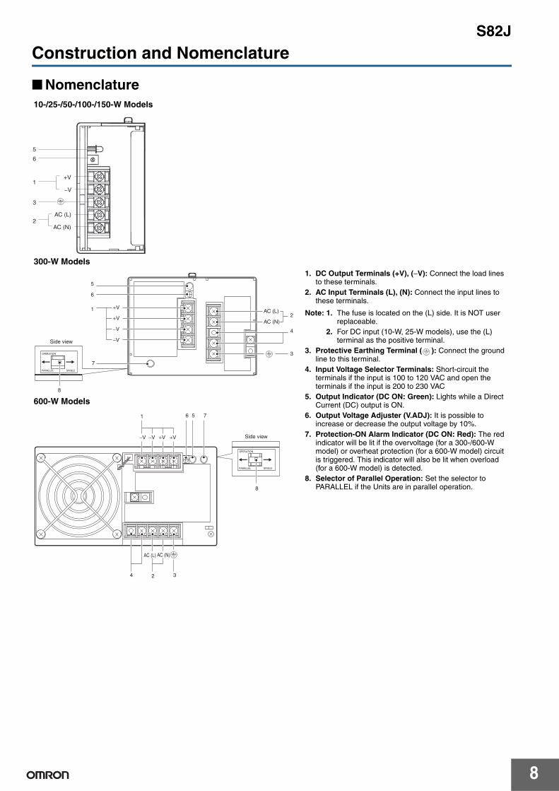
Construction and Nomenclature
■ Nomenclature10-/25-/50-/100-/150-W Models
300-W Models1. DC Output Terminals (+V), (−V): Connect the load lines
to these terminals.2. AC Input Terminals (L), (N): Connect the input lines to
these terminals.
Note: 1. The fuse is located on the (L) side. It is NOT user replaceable.
2. For DC input (10-W, 25-W models), use the (L) terminal as the positive terminal.
3. Protective Earthing Terminal ( ): Connect the ground line to this terminal.
4. Input Voltage Selector Terminals: Short-circuit the terminals if the input is 100 to 120 VAC and open the terminals if the input is 200 to 230 VAC
5. Output Indicator (DC ON: Green): Lights while a Direct Current (DC) output is ON.
6. Output Voltage Adjuster (V.ADJ): It is possible to increase or decrease the output voltage by 10%.
7. Protection-ON Alarm Indicator (DC ON: Red): The red indicator will be lit if the overvoltage (for a 300-/600-W model) or overheat protection (for a 600-W model) circuit is triggered. This indicator will also be lit when overload (for a 600-W model) is detected.
8. Selector of Parallel Operation: Set the selector to PARALLEL if the Units are in parallel operation.
600-W Models
5
6
1
3
2
+V
−V
AC (L)
AC (N)
+V
+V
−V
−V
5
6
1 AC (L)
AC (N)2
4
3
8
7
Side view
1 6 5 7
8
4 2 3
AC (L) AC (N)
Side view−V +V−V +V

S82J
9
Engineering Data
■ Derating Curve(for Standard Mounting)
10-/25-/50-/100-/150-W Model
300-W Model
Note: Provide a minimum clearance of 20 mm between the Power Supplies.
600-W Model
Note: Provide a minimum clearance of 20 mm between the Power Supplies.
Natural air-coolingNatural air-cooling
Open-frame Type
Load
rat
io (
%)
Ambient temperature (°C)
Covered Type
Load
rat
io (
%)
Ambient temperature (°C)
Standard Mounting
Forced air-cooling (1 m3/min) Forced air-cooling (1 m3/min)
Note: The derating curve shown is for standard mounting. The derating curve depends on the mounting direction of the Power Supply.
120 120
100 100
Single-unit Operation Parallel Operation Standard Mounting
20 mm min. 20 mm min.
20 mm min. 20 mm min.
Load
rat
io (
%)
Ambient temperature (°C)
Load
rat
io (
%)
Ambient temperature (°C)
Forced air-cooling (1 m3/min) (Standard mounting)
Natural air-cooling (Standard mounting) Forced air-cooling (1 m3/min)(Side mounting)
Natural cooling (Side mounting)
Forced air-cooling (1 m3/min) (Standard mounting)
Natural air-cooling (Standard mounting)Forced air-cooling (1 m3/min)(Side mounting)
Natural cooling (Side mounting)
120
100100
120
Single-unit Operation Parallel Operation Standard Mounting
Load
rat
io (
%)
Ambient temperature (°C)
Load
rat
io (
%)
Ambient temperature (°C)
20 mm min. 20 mm min.
20 mm min. 20 mm min.

S82J
10
■ Overload Protection10- to 300-W ModelsThe Power Supply is provided with an overload protection function that protects the Power Supply from possible damage by overcurrent. When the output current rises above 105% to 160% of the rated output current, the protection function is triggered, automatically decreasing the output voltage. When the output current falls within the rated range, the overload protection function is automatically cleared.
The values shown in the above diagrams are for reference only.
Note: 1. If the S82J is connected to a load with a built-in DC-DC converter, the overload protection function may be triggered at startup, and consequently the S82J may not operate.
2. Internal parts may occasionally deteriorate or be damaged if a short-circuited or other overcurrent state continues during operation. Eliminate the overcurrent state as soon as possible.
3. In actual operation, the output voltage may not fall to 0 V when the overload protection function is triggered. Even with short-circuits on the load side, the drop in voltage will vary depending on factors such as the impedance in the load line.
4. The overload protection function is specified at 105% or more of the rated output current for 300-W models.
600-W Models
If an excessive current flows for 5 s or more, the output will be turned OFF and simultaneously the protection-ON alarm indicator will be lit. To reset the S82J, turn OFF the power, leave the S82J for at least three minutes, and then turn it ON again.
Note: Internal parts may occasionally deteriorate or be damaged if a short-circuited state continues during operation.Eliminate the overcurrent state as soon as possible.
■ Overvoltage Protection100-W (5-, 24-V Output) Models Consider the possibility of an overvoltage and design the system so that the load will not be subjected to an excessive voltage even if the feedback circuit in the Power Supply fails. When an excessive voltage that is approximately 120% of the rated voltage or more is output, the output voltage is shut OFF, preventing damage to the load due to overvoltage. Reset the input power by turning it OFF for at least one minute and then turning it back ON again.
The values shown in the above diagram are for reference only.
300- and 600-W ModelsWhen an excessive voltage that is approximately 120% of the rated voltage or more is output, the output voltage will be turned OFF and simultaneously the protection-ON alarm indicator will be lit. Reset the input power by turning it OFF for at least three minutes (90 seconds for 300-W models) and then turning it back ON again.
■ Overheat Protection Function600-W Models OnlyIf the internal temperature rises excessively as a result of fan failure or any other reason, the overheat protection circuit will be triggered to protect the internal parts and simultaneously the protection-ON alarm indicator will be lit. Reset the input power by turning it OFF for at least three minutes and then turning it back ON again.
■ Inrush Current, Startup Time, Hold Time
Note: Models with a 100 to 240 V (free) input have a higher inrush current energy than models with a single rated input voltage or models with a switchable input voltage. Be sure to coordinate breaker with the inrush current energy.
10 W, 25 W Models
50 W, 100 W (24-V) Models
100 W (5-V, 12-V, 15-V), 150 W, 300 W Models
0Output current (%)
10050
Intermitted operation
Out
put v
olta
ge (
V)
500 100Output current (%)
Intermitted operation
Out
put v
olta
ge (
V)
0 10050
Out
put v
olta
ge (
V)
Output current (%)
50
Output interrupted
0 100Output current (%)
Out
put v
olta
ge (
V)
Voltage adjustable range
Out
put v
olta
ge (
V)
Rated output voltage
Overvoltage protection operates
90% 96.5%
Input ON Input OFF
Startup time
Inrush current on input application
AC input voltage
AC input current
Output voltage Hold time
(20 ms min.)

S82J
11
DimensionsNote: All units are in millimeters unless otherwise indicated.
Open-frame type and covered type have the same dimensions.
■ Front-mounting Bracket ModelsS82J-010@@@ (10 W)
S82J-025@@@ (25 W)
S82J-050@@@ (50 W)
82±0.5
65±0.5
78±0.5
Side Mounting
Bottom Mounting
Two, M3
Two, M3
Mounting Holes (Surface Screw Mounting)
112±0.5
65±0.5
116±0.5
Side Mounting
Bottom Mounting
Two, M3
Two, M3
Mounting Holes(Surface Screw Mounting)
AC
AC
+V
−V
Protective earthing terminal PE−V+V
Output voltage adjuster (V. ADJ)Output indicator (Green)
AC (L)AC (N)
DC output terminal
Input terminal
90±1
97±1
3.5
65±0.5
82±0.55 5
3.5 dia.
12 max.
3.5 dia.6.5
50±0.5
78±0.5
35±1
3.5
17.528
15
Two, M3
8.29.5
Five, M3.5
Nameplate
8.29.5
Five, M3.5
Nameplate
8.29.5
Five, M3.5
Nameplate
AC
AC
+V
−V
3.5 dia.
12 max. 161±1
3.5
7
65±0.5
97±1
153±0.55
20±0.5
10
20
6.5 150.5±0.5
3.5 dia.
Three, M340±1
3.5
28
22
Protective earthing terminal PE−V+V
Output voltage adjuster (V. ADJ)Output indicator (Green)
AC (L)AC (N)
DC output terminal
Input terminal
127±0.5
153±0.5
65±0.5
150.5±0.5
Side Mounting
Bottom Mounting
Two, M3
Two, M3
Mounting Holes(Surface Screw Mounting)
AC
AC
+V
−V
Protective earthing terminal PE−V+V
Output voltage adjuster (V. ADJ)Output indicator (Green)
AC (L)AC (N)
DC output terminal
Input terminal
3.5
6116±0.55
12 max. 124±1
3.5 dia.
6.5 112±0.5
3.5 dia.
40±1
3.5
2817.5
Three, M3
83±0.521.5
65±0.5
97±1

S82J
12
162±0.5
65±0.5
160±0.5
Two, M4
Two, M4
Mounting Holes(Surface Screw Mounting)
Side Mounting
Bottom Mounting
S82J-10024@ (100 W, 24-V Output)
Five, M3.5
Nameplate
Protective earthing terminal PE−V+V
Output voltage adjuster (V. ADJ)Output indicator (Green)
AC (L)AC (N)
DC output terminal
Input terminal
12 max. 170±1
65±0.5
97±1
162±0.5
4.5 dia.
25±0.5 50±1
28±0.5
Three, M44.5 dia.
160±0.5
100±0.5
4.5
75
8.29.5
27.5
15
4.5
6.5
15
180±0.5
82±0.8
178±0.5
4.5 dia.
Mounting holes (on both sides)
Side Mounting
Bottom Mounting
Two, M4
Two, M4
S82J-100@@@ (100 W, 5-/12-/15-V Output) S82J-15024@ (150 W)
Three, M4 (depth: 6 max.)
Mounting Holes(Surface Screw Mounting)
188
4.5
89±0.5 97
3±0.25
3±0.25
4.5
15
5025±0.5
55±0.3100±0.5
27.5±0.335±0.3
180±0.5
178±0.5
7±0.3Eight, M4
8.1
9.5
4 max.
198 (see note)
4.5 dia.
150±0.5
50±0.5
150±0.5
100±0.5
S82J-30024@ (300 W)
Four, M4 holes (depth: 8 max.)
Nine, M4 terminal screws
Side
Side Mounting
Bottom Mounting
Four, 4.5 dia.
Four, 4.5 dia.
Eight, M4 holes (depth: 8 max. on both sides)
Mounting Holes(Surface Screw Mounting)
-V
OUTPUT
SHORT BAR
INPUT 50/60Hz
N
L
MADE IN JAPAN
AC100-120V 8AAC200-230V 4A
OMRON Corporation
VOLTAGE SELECTSHORT 100-120VOPEN 200-230V
POWER SUPPLY
DC ON
V. ADJ
DC24V 14A
ALM
+V
OPERATION
PARALLEL SINGLE
120±1
150±0.5
100±0.5
50±0.5
10
21
150±0.5
181±1
19
19
(19)
92±18.6
10
4

S82J
13
■ Dimensions with Mounting BracketsNote: Panel mounting screw are not supplied.
Front-mounting Bracket (Supplied)
150±0.5
50±0.5
150±0.5
100±0.5
S82J-60024@ (600 W)
Four, M4 holes (depth: 8 max. on one side)
Nine, M4 terminal screws
Side Mounting
Bottom Mounting
Four, 4.5 dia.
Four, 4.5 dia.
Mounting Holes(Surface Screw Mounting)
Eight, M4 holes (depth: 8 max. on both sides)
Four, M4 holes (depth: 8 max.)
Material: Stainless steel
(b)
(b)
(a)
(a)
Mounting bracket Power supply unit
60
20
Mounting Holes
Two, M3
1.5 11
9
60
520
31.5
15
20.5
4.7
4.611
74
15±0.24.6
t=1.0
Two, 3.5 dia.
Attach the mounting bracket to the panel and loosely tighten the two screws. Insert the projected parts of the bracket (b) to the square holes of the power supply (a). Then securely tighten the screws.
Using the Mounting BracketFor 10-/25-/50-/100 (24 V)-W Models
Note: The mounting screws are not provided.
30±0.5
110±0.5
381.5
6.5
11
t=0.8
23.5
Mounting bracket
120 max.
Two, 5 dia.
Attaching the Mounting Brackets
5 dia.
Dimensions with Mounting BracketsFor 100- (5, 12, 15 V) and 150-W Models
Note: The brackets are for front-mounting.

S82J
14
300-W and 600-W Models
Note: A mounting bracket is included with the S82J-30024 and S82J-60024, but not with the S82J-30024N and S82J-60024N.
Note: To provide ventilation space, the body will shift forward by 21.6 mm from the mounting surface.
Note: To provide ventilation space, the body will shift forward by 23.6 mm from the mounting surface.
145±0.5
90±0.5 Four, M4
NL
145±0.5
140±0.5 Four, M4
48
t=1.6
1530
7.5 7.5
160
145±0.5
R2.510 dia.
3236.4±0.2
92Four, 5 dia.
Note: Mounting Brackets are provided in a set, one for the right side and one for the left side.
Dimensions with Mounting BracketsFor 300-W Models
Dimensions with Mounting BracketsFor 600-W Models
Attaching the Mounting BracketsFor 300-W Models
Attaching the Mounting BracketsFor 600-W Models
For 300-W Models (S82Y-J30F)

S82J
15
■ DIN Rail Mounting Bracket ModelsNote: All units are in millimeters unless otherwise indicated. The open-frame type and connected type have the same dimensions.
S82J-010@@@D (10 W)
S82J-025@@@D (25 W)
(Sliding: 9 max.)
(Sliding: 9 max.)
7 max. 12 max.
7 max. 12 max.
Five, M3.5
Five, M3.5
S82J-050@@@D (50 W)
(Sliding: 9 max.)
(Sliding: 9 max.)
S82J-10024@D (100 W, 24-V Output)
7 max. 12 max.
7 max. 12 max.
Five, M3.5
Five, M3.5

S82J
16
(Sliding: 9 max.)
S82J-100@@@D (100 W, 5-/12-/15-V Output) S82J-15024@D (150 W)
7 max.
4 max.Eight, M4
S82J
17
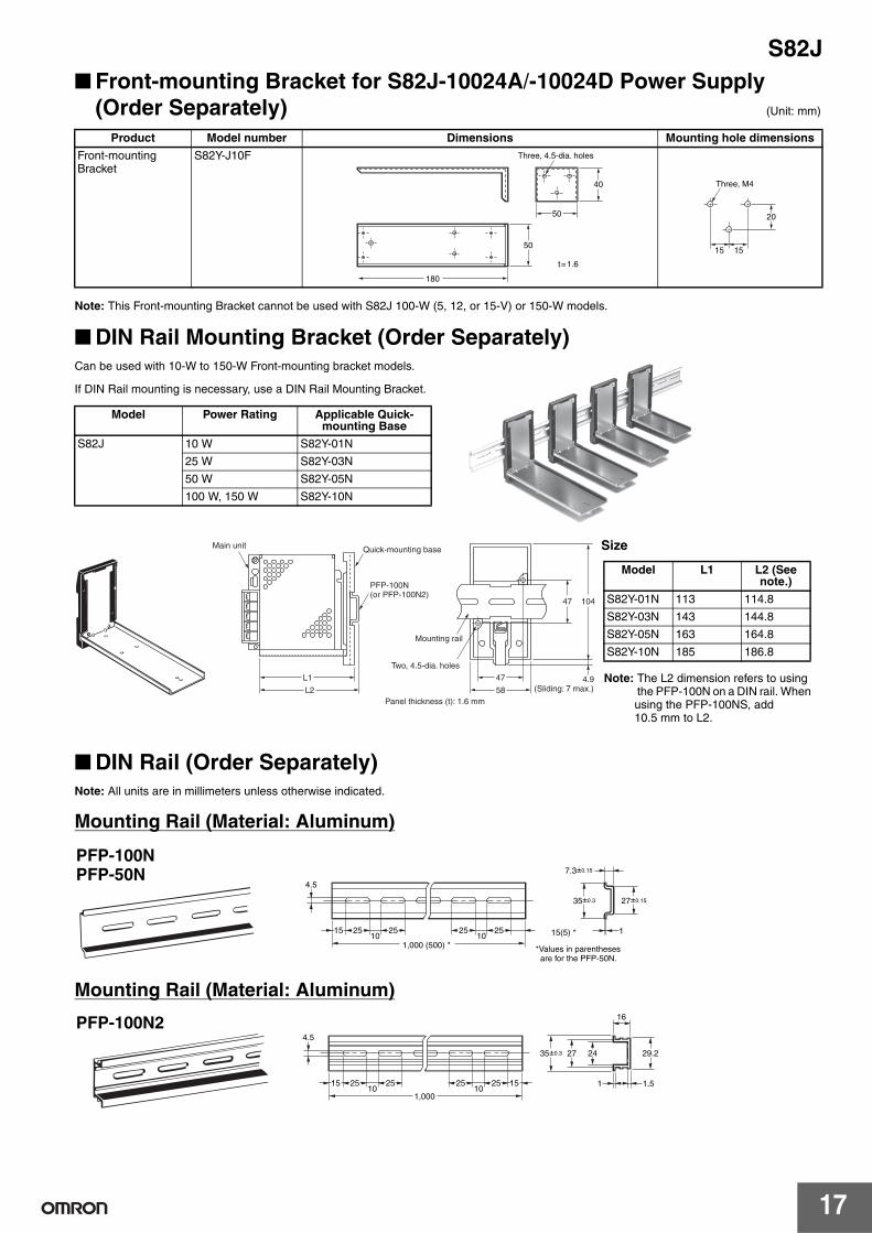
■ Front-mounting Bracket for S82J-10024A/-10024D Power Supply (Order Separately) (Unit: mm)
Note: This Front-mounting Bracket cannot be used with S82J 100-W (5, 12, or 15-V) or 150-W models.
■ DIN Rail Mounting Bracket (Order Separately) Can be used with 10-W to 150-W Front-mounting bracket models.
If DIN Rail mounting is necessary, use a DIN Rail Mounting Bracket.
■ DIN Rail (Order Separately)Note: All units are in millimeters unless otherwise indicated.
Mounting Rail (Material: Aluminum)
Mounting Rail (Material: Aluminum)
Product Model number Dimensions Mounting hole dimensions
Front-mounting Bracket
S82Y-J10F
180
50
t=1.6
40
50
Three, 4.5-dia. holes
Three, M4
20
1515
Model Power Rating Applicable Quick-mounting Base
S82J 10 W S82Y-01N
25 W S82Y-03N
50 W S82Y-05N
100 W, 150 W S82Y-10N
Mounting rail
Two, 4.5-dia. holes
47 4.9(Sliding: 7 max.)
PFP-100N (or PFP-100N2)
Quick-mounting baseMain unit
L1
L2
47 104
58Panel thickness (t): 1.6 mm
Size
Note: The L2 dimension refers to using the PFP-100N on a DIN rail. When using the PFP-100NS, add 10.5 mm to L2.
Model L1 L2 (See note.)
S82Y-01N 113 114.8
S82Y-03N 143 144.8
S82Y-05N 163 164.8
S82Y-10N 185 186.8
1,000 (500) *
15(5) *
*Values in parentheses are for the PFP-50N.
PFP-100N PFP-50N
4.5
15 25 2510 10
25 25
35±0.3
7.3±0.15
27±0.15
1
PFP-100N24.5
15 25 2510 10
1,000
25 25 15 1 1.5
29.2242735±0.3
16

S82J
18
Safety PrecautionsRefer to Safety Precautions for All Power Supplies.
!CAUTION
■ Precautions for Safe UseMountingTo improve and maintain the reliability of the Power Supply over a long period of time, adequate consideration must be given to heat radiation.
The Power Supply is designed to radiate heat by means of natural air-flow. Therefore, mount the Power Supply so that air flow takes place around the Power Supply.
When mounting the Power Supply, mounting it to a metal plate is recommended.
When mounting two or more Power Supplies side-by-side, allow at least 20 mm spacing between them, as shown in the following illustration.
Forced air-cooling is recommended.
Mounting MethodsThe following mounting methods are available.
10-/25-/50-/100 (24-V Output)-W Models(A) Side mounting(B) Bottom mounting(C) Front mounting (see Accessories)
Note: Refer to the section on the Mounting Bracket.
100 (-5, -12, -15 V Output)/150-/300-/600-W ModelsThe following 4 mounting methods are possible.
(A) Side mounting
(B) Bottom mounting (secured with screws from the inside of the Switching Power Supply) (except for 300- and 600-W models)
(C) Bottom mounting (secured with screws from the back of the Switching Power Supply)
(D) Front mountingFront mounting is possible with the mounting brackets provided. Refer to Dimensions on page 11.
WiringConnect the ground completely. Electric shock or malfunction may occur if the ground is not connected completely.
Tighten terminal screws to the following specified torque.
Do not apply more than 75-N force to the terminal block when tightening it.
Minor electric shock, fire, or Product failure may occasionally occur. Do not disassemble, modify, or repair the Product or touch the interior of the Product.
Minor burns may occasionally occur. Do not touch the Product while power is being supplied or immediately after power is turned OFF.
Fire may occasionally occur. Tighten terminal screws to the specified torque 0.74 N·m for 10-, 25-, 50-, or 100-W models (24-V output); or 1.08 N·m for 100- (5-, 12-, or 15-V output), 150-, 300-, or 600-W models.
Minor injury due to electric shock may occasionally occur. Do not touch the terminals while power is being supplied.
Minor electric shock, fire, or Product failure may occasionally occur. Do not allow any pieces of metal or conductors or any clippings or cuttings resulting from installation work to enter the Product.
Air
Metal plate20 mm min.
(B)
(A)
Capacity Terminal screws
Torque
10-, 25-, 50-, or 100-W (24 V) M3.5 0.74 N·m
100-W (5-, 12-, or 15-V), 150-, 300-, 600-W M4 1.08 N·m
(A)
(B)
(C)
Metal plate
Mounting brackets (provided)

S82J
19
Switching the AC Input Voltage between 100 and 200 V (300- and 600-W Models)The input voltage can be switched between 100 and 200 V by shorting or opening the input voltage selection terminals. Set the required voltage as shown below. (The voltage is factory-set to 200 V.)
Note: A 300-W Model is shown above.
Series OperationOnly models with power ratings of 50, 100 (-5, -12, -15, 24-output), 150, 300, or 600-W allow series operation.
Up to two of the above Power Supplies can be used in series operation. Models other than the above Power Supplies cannot be used in series operation.
If series operation is attempted for other models, the output from one of the Power Supplies may not come ON when the AC input is applied. If that occurs and the Power Supplies are left in that state, internal circuits may be damaged.
Although Power Supplies having different output capacities and different output voltages can be connected in series, the current flowing through the load must not exceed the smaller rated output current.
With the S82J-05024@@ or S82J-10024@@, if the load is shorted a reverse voltage may result in the Power Supply causing deterioration and damage. It is recommended that diodes are connected as shown in the previous diagram (D1, D2).
Parallel OperationOnly 300- and 600-W models can be in parallel operation. Do not operate any other models in parallel. The output of the models in parallel operation is a maximum of 80% of the rated output.
Set the parallel operation selector to PARALLEL if the Units are in parallel operation and make sure that the thickness and the length of all wires connected to the load are the same to ensure that the wires will have no voltage drop differences.
If you adjust the voltage using the output voltage adjuster (V.ADJ), adjust the output voltage from both Power Supplies.
Fan ReplacementThe service life of the fan is approximately 50,000 hours (at 25°C). The service life varies, however, depending on the ambient temperature or other surrounding environmental conditions such as dust. As a preventive maintenance measure, replace the fan within approx. two years if it is used at an ambient temperature of 40°C.
Fans are available as replacements.
Fan Set:Fan (above), four M4 x 35 sems screws, instruction sheet, and packing case
Replace the fan as shown in the following illustration.Model Output capacity Rated output voltage
S82J 100 W 5, 12, 15, 24 VDC
50, 150, 300, 600 W 24 VDC
Type Schottky barrier diodeDielectric strength (VRRM)
Twice the rated output voltage or above
Forward current (IF) Twice the rated output current or above
SHORT BAR
N
L
MADE IN JAPANOMRON Corporation
VOLTAGE SELECTSHORT 100-120VOPEN 200-230V
100-V input
SHORT BAR
N
L
MADE IN JAPANOMRON Corporation
VOLTAGE SELECTSHORT 100-120VOPEN 200-230V
200-V input
Short with the short bar. Remove the short bar and leave the terminals open.
INPUT+V
V1D1
VL
V2D2
VL V1 V2
−V
INPUT+V
−V
Load
+=
Model: S82Y-JFAN
In the interest of product improvement, specifications are subject to change without notice.
ALL DIMENSIONS SHOWN ARE IN MILLIMETERS.
To convert millimeters into inches, multiply by 0.03937. To convert grams into ounces, multiply by 0.03527.

Read and Understand This Catalog Please read and understand this catalog before purchasing the products. Please consult your OMRON representative if you have any questions or comments.
Warranty and Limitations of Liability WARRANTY OMRON's exclusive warranty is that the products are free from defects in materials and workmanship for a period of one year (or other period if specified) from date of sale by OMRON. OMRON MAKES NO WARRANTY OR REPRESENTATION, EXPRESS OR IMPLIED, REGARDING NON-INFRINGEMENT, MERCHANTABILITY, OR FITNESS FOR PARTICULAR PURPOSE OF THE PRODUCTS. ANY BUYER OR USER ACKNOWLEDGES THAT THE BUYER OR USER ALONE HAS DETERMINED THAT THE PRODUCTS WILL SUITABLY MEET THE REQUIREMENTS OF THEIR INTENDED USE. OMRON DISCLAIMS ALL OTHER WARRANTIES, EXPRESS OR IMPLIED. LIMITATIONS OF LIABILITY OMRON SHALL NOT BE RESPONSIBLE FOR SPECIAL, INDIRECT, OR CONSEQUENTIAL DAMAGES, LOSS OF PROFITS OR COMMERCIAL LOSS IN ANY WAY CONNECTED WITH THE PRODUCTS, WHETHER SUCH CLAIM IS BASED ON CONTRACT, WARRANTY, NEGLIGENCE, OR STRICT LIABILITY. In no event shall the responsibility of OMRON for any act exceed the individual price of the product on which liability is asserted. IN NO EVENT SHALL OMRON BE RESPONSIBLE FOR WARRANTY, REPAIR, OR OTHER CLAIMS REGARDING THE PRODUCTS UNLESS OMRON'S ANALYSIS CONFIRMS THAT THE PRODUCTS WERE PROPERLY HANDLED, STORED, INSTALLED, AND MAINTAINED AND NOT SUBJECT TO CONTAMINATION, ABUSE, MISUSE, OR INAPPROPRIATE MODIFICATION OR REPAIR.
Application Considerations SUITABILITY FOR USE OMRON shall not be responsible for conformity with any standards, codes, or regulations that apply to the combination of products in the customer's application or use of the products. At the customer's request, OMRON will provide applicable third party certification documents identifying ratings and limitations of use that apply to the products. This information by itself is not sufficient for a complete determination of the suitability of the products in combination with the end product, machine, system, or other application or use. The following are some examples of applications for which particular attention must be given. This is not intended to be an exhaustive list of all possible uses of the products, nor is it intended to imply that the uses listed may be suitable for the products:
• Outdoor use, uses involving potential chemical contamination or electrical interference, or conditions or uses not described in this catalog. • Nuclear energy control systems, combustion systems, railroad systems, aviation systems, medical equipment, amusement machines, vehicles,
safety equipment, and installations subject to separate industry or government regulations. • Systems, machines, and equipment that could present a risk to life or property.
Please know and observe all prohibitions of use applicable to the products. NEVER USE THE PRODUCTS FOR AN APPLICATION INVOLVING SERIOUS RISK TO LIFE OR PROPERTY WITHOUT ENSURING THAT THE SYSTEM AS A WHOLE HAS BEEN DESIGNED TO ADDRESS THE RISKS, AND THAT THE OMRON PRODUCTS ARE PROPERLY RATED AND INSTALLED FOR THE INTENDED USE WITHIN THE OVERALL EQUIPMENT OR SYSTEM. PROGRAMMABLE PRODUCTS OMRON shall not be responsible for the user's programming of a programmable product, or any consequence thereof.
Disclaimers CHANGE IN SPECIFICATIONS Product specifications and accessories may be changed at any time based on improvements and other reasons. It is our practice to change model numbers when published ratings or features are changed, or when significant construction changes are made. However, some specifications of the products may be changed without any notice. When in doubt, special model numbers may be assigned to fix or establish key specifications for your application on your request. Please consult with your OMRON representative at any time to confirm actual specifications of purchased products. DIMENSIONS AND WEIGHTS Dimensions and weights are nominal and are not to be used for manufacturing purposes, even when tolerances are shown. PERFORMANCE DATA Performance data given in this catalog is provided as a guide for the user in determining suitability and does not constitute a warranty. It may represent the result of OMRON’s test conditions, and the users must correlate it to actual application requirements. Actual performance is subject to the OMRON Warranty and Limitations of Liability. ERRORS AND OMISSIONS The information in this document has been carefully checked and is believed to be accurate; however, no responsibility is assumed for clerical, typographical, or proofreading errors, or omissions.
2011.1
In the interest of product improvement, specifications are subject to change without notice.
OMRON Corporation Industrial Automation Company http://www.ia.omron.com/
(c)Copyright OMRON Corporation 2011 All Right Reserved.