SWITCH AND CONTROL MODULE REFERENCE · Processors and General Computing Processors and the Command...
112
www.radisys.com PROMENTUM™ SWITCH AND CONTROL MODULE REFERENCE ATCA-2210 ATCA-2210 WITH CE3100 007-02376-0003 • June 2008
Transcript of SWITCH AND CONTROL MODULE REFERENCE · Processors and General Computing Processors and the Command...

www.radisys.com
PROMENTUM™SWITCH AND CONTROL MODULE REFERENCE
ATCA-2210ATCA-2210 WITH CE3100
007-02376-0003 • June 2008

2
Release history
Release Date Description-0000 January 2006 First release.-0001 September 2007 Editorial changes and new features. See release notes for information on new
features.-0002 November 2007 Editorial changes and added information on COM Express. -0003 May 2008 Editorial changes and removed software and command line information. The
software information now resides in the Software Guide and the command line information resides in the CLI Reference. Added diagnostics information.
Copyright © 2006-2008 by RadiSys Corporation. All rights reserved. RadiSys is a registered trademark and Promentum and Procelerant are a trademarks of RadiSys Corporation. AdvancedTCA, ATCA, and PIGMG are registered trademarks of PCI Industrial Computer Manufacturers Group. Wind River is a registered trademark of Wind River Systems Inc. Red Hat and Enterprise Linux are registered trademarks of Red Hat Inc. Procomm Plus and Symantec are registered trademarks of Symantec Corporation. Intel is a registered trademark of Intel Corporation. Linux is a registered trademark of Linus Torvalds. All other trademarks, registered trademarks, service marks, and trade names are the property of their respective owners.
3
TABLE OF CONTENTS
Preface ................................................................................................................................................................ 5About this manual....................................................................................................................................................................... 5Where to get more product information ............................................................................................................................... 5About related RadiSys Products ............................................................................................................................................... 6Standards information................................................................................................................................................................ 6Related documents ..................................................................................................................................................................... 6Notational conventions .............................................................................................................................................................. 7Electrostatic discharge ................................................................................................................................................................ 7
Chapter 1: Introduction to the SCM................................................................................................................ 9Possible applications of the SCM............................................................................................................................................10The SCM as a Shelf Manager...................................................................................................................................................10Redundancy.................................................................................................................................................................................10Local management processor .................................................................................................................................................11Intelligent Platform Management ...........................................................................................................................................11Ethernet interfaces .................................................................................................................................................................... 13Network timing subsystem...................................................................................................................................................... 15COM Express and drive ............................................................................................................................................................16Installed software........................................................................................................................................................................16External connectivity ..................................................................................................................................................................16Connecting to the SCM.............................................................................................................................................................17Logging in to the SCM ..............................................................................................................................................................17
Chapter 2: Subsystems and Components.................................................................................................... 19Local management processor ................................................................................................................................................ 20Flash memory layout................................................................................................................................................................ 25Clock synthesizer subsystem .................................................................................................................................................. 28Base Ethernet switch subsystem............................................................................................................................................ 28Fabric Ethernet switch subsystem.......................................................................................................................................... 33LED controller interface subsystem....................................................................................................................................... 37Network timing subsystem...................................................................................................................................................... 38

4
Table of Contents
Hardware management subsystem ......................................................................................................................................40Power supplies........................................................................................................................................................................... 43
Chapter 3: COM Express Subsystem............................................................................................................. 45
Chapter 4: Physical Interfaces........................................................................................................................ 55Mechanical specification ..........................................................................................................................................................56Front panel interfaces and LEDs............................................................................................................................................56Backplane interfaces .................................................................................................................................................................64Rear transition module............................................................................................................................................................. 71Internal interfaces...................................................................................................................................................................... 75
Chapter 5: Diagnostic Tests and Commands ............................................................................................... 77POST diagnostics ....................................................................................................................................................................... 78Manufacturing diagnostics.......................................................................................................................................................80
Chapter 6: Maintenance and Troubleshooting............................................................................................ 87Maintenance ............................................................................................................................................................................... 87Troubleshooting.........................................................................................................................................................................89
Appendix A: Specifications ............................................................................................................................. 91Environmental ............................................................................................................................................................................ 91Safety............................................................................................................................................................................................ 92Mechanical dimensions ........................................................................................................................................................... 92Electromagnetic compatibility (EMC) ................................................................................................................................... 93Power .......................................................................................................................................................................................... 93Reliability .....................................................................................................................................................................................94
Appendix B: IPMI commands and Managed Sensors ................................................................................ 95IPMI commands ........................................................................................................................................................................ 95Sensors on the SCM ................................................................................................................................................................. 97Board health and event generation .....................................................................................................................................101Alarms troubleshooting.......................................................................................................................................................... 105

5
PREFACE
About this manualThis manual describes the Promentum™ ATCA-2210, a switch and control module (SCM), which is fully compliant with AdvancedTCA® (ATCA®). The SCM is designed to be incorporated into High Availability (HA) systems such as the Promentum platforms SYS-6006 and SYS-6010.
Use this manual as a hardware reference for the operation and maintenance of the ATCA-2210 SCM. The manual also provides information on the electrical, the mechanical, and the environmental aspects of the ATCA-2210 SCM. The material presented here is not introductory; it is assumed that you are already familiar with the intended use of the ATCA-2210 SCM in your organization’s ATCA platform.
The simplified names “SCM” and “module” will be used in place of “ATCA-2210 SCM” for the rest of this manual.
Note: The software material that appeared in this manual prior to Promentum release 3.2.0 has been removed. This information now resides in the Software Guide for Management Processors and General Computing Processors and the Command Line Interface Reference. These manuals consolidate the software information for the Promentum modules. As a result, the Ethernet Switching Software Reference and the IP Routing Software Reference are discontinued, and the reference manuals for the modules now focus on hardware and troubleshooting information.
Where to get more product information Please visit the RadiSys Web site at www.radisys.com for product information and other resources. Downloads (manuals, release notes, software, etc.) are available via the Technical Support Library product links at www.radisys.com/support or the product pages at www.radisys.com/products.
See the following resources for information on the SCM not described in this manual:Installation and initial setup instructions. The ATCA-2210 Switch and Control Module Installation Guide provides the steps for installing the SCM into a shelf and completing the initial configuration.
Command line interface (CLI) reference information. The Command Line Interface Reference describes the master CLI and its command modes and serves as a reference for command syntax and options. When referenced in this manual, the simplified name of CLI Reference will be used.
Software reference information. The Software Guide for Management Processors and General Computing Processors describes software concepts and serves as a reference for procedural and usage information. When referenced in this manual, the simplified name of Software Guide will be used.

6
Preface
Shelf Manager information. The Shelf Management Software Reference describes the architecture and the operation of the Shelf Manager. The Shelf Manager runs on the SCM and controls and monitors operations on the shelf.
Update information. Firmware and software updates may be available for the SCM components from time to time. For information on updating components on the SCM and other modules, see the Firmware and Software Update Instructions.
About related RadiSys ProductsThe SCM is part of the Promentum SYS-6006 and SYS-6010 platforms. For information on the Promentum product family and other RadiSys products, see the RadiSys Web site at www.radisys.com.
Standards informationFor information about the PCI Industrial Computer Manufacturers Group (PICMG®) and the AdvancedTCA standard, consult the PICMG Web site at this URL:http://www.picmg.org
Related documentsCAN/CSA 22.2 No. 60950-1-03 Safety for Information Technology Equipment, Version 2, Canadian Standards Association (CSA), April, 1, 2003.
EN 60950-1:2002 Safety for Information Technology Equipment, European Committee for Electrotechnical Standardization (CENELEC), February 22, 2002.
GR-63-CORE NEBS Requirements Physical Protection, Issue 2, Telcordia, April 2002.
GR-78-CORE Generic Requirements for the Physical Design and Manufacture of Telecommunications Products and Equipment, Issue 1, Telcordia, September 1997.
GR-1089-CORE Electromagnetic Compatibility and Electrical Safety – Generic Criteria for Network Telecommunications Equipment, Issue 3, Telcordia, October 2002.
IEC 60950-1 Safety for Information Technology Equipment, International Electrotechnical Commission (IEC), October 25, 2001.
INF-8077i 10 Gigabit Small Form Factor Pluggable Module (XFP), Revision 4.5, XFP Multi Source Agreement (MSA) Group, August 31, 2005.
PICMG 3.0 R2.0 Advanced Telecommunications Computing Architecture (AdvancedTCA), PICMG, March 18, 2005.
PICMG 3.1 R1.0 Ethernet/Fibre Channel for AdvancedTCA Systems, PICMG, January 22, 2003.
PICMG COM.0 R1.0 COM Express™ Module Base Specification, PICMG, July 10, 2005.
Service Availability Forum Hardware Platform Interface Specification (SAF HPI Specification), SAI-HPI-B.01.01, 2004.

7
Notational conventions
Small Form-factor Pluggable (SFP) Transceiver Multisource Agreement (MSA), Cooperation Agreement for Small Form-Factor Pluggable Transceivers, Agilent Technologies, Blaze Network Products, E2O Communications, Inc., ExceLight Communications, Finisar Corporation, Fujikura Technology America Corp., Hitachi Cable, Infineon Technologies Corp., IBM Corp., Lucent Technologies, Molex, Inc., Optical Communication Products, Inc., Picolight, Inc., Stratos Lightwave, and Tyco Electronics, September 14, 2000.
UL 60950-1 Safety for Information Technology Equipment, Underwriter Laboratories (UL), April 2003.
Notational conventionsThis manual uses the following conventions
All numbers are decimal unless otherwise stated.
Electrostatic discharge WARNING! This product contains static-sensitive components and should be handled with care. Failure to employ adequate anti-static measures can cause irreparable damage to components.
Electrostatic discharge (ESD) damage can result in partial or complete device failure, performance degradation, or reduced operating life. To avoid ESD damage, the following precautions are strongly recommended.
Keep each module/PCB in its ESD shielding bag until you are ready to install it.Before touching a module, attach an ESD wrist strap to your wrist and connect its other end to a known ground. Handle the module only in an area that has its working surfaces, floor coverings, and chairs connected to a known ground.Hold modules only by their edges and mounting hardware. Avoid touching PCB components and connector pins.
For further information on ESD, visit www.esda.org.
BoldText A keyword.
ItalicText File, function, and utility names.
MonoText Screen text and syntax strings.
BoldMonoText A command to enter.
ItalicMonoText Variable parameters.
Brackets [ ] Command options.
Curly braces { } A grouped list of parameters.
Vertical line | An “OR” in the syntax. Indicates a choice of parameters.

8
Preface

9
1INTRODUCTION TO THE SCM
The SCM supports inter-node connectivity by providing Base and Fabric Ethernet switching and system clock synchronization. The SCM can act as a Shelf Manager and also includes a site for a COM Express processing module, which can be used for system management.
Figure 1. SCM system block diagram
E1/DS1framerBase
Ethernetswitch
COM Express
1 Gb
10 Gb10 Gb
IPMB
1-3
RTM (example)
SCMBlue = Base EthernetRed = Fabric Ethernet
SFP
SFP
SFP
SFP
SFP
SFP
SFP
SFP
RJ45
RJ45
RJ45
RJ45
RS-232
USB
1 Gb Eth
RS-232
FE
RJ45
RJ45
XFP
XFP
XFP
XFP
XFP
SFP
SFP
SFP
SFP -48 V power conversion
Local power conversion
ShMCIPMC
RTC
10 Gb
1 Gb
4
12 V
PCI
PCI
1 Gb
10 Gb
Serial
FEswitch
Zone1
Zone2
Nodeslots
ShMgr
Nodeslots
Updchan
Syncchan
Zone2
Clk
Clk
Sync
1 Gb100 Mb
10 Gb
12-14
FE
2FE
1 Gb-Tx
12-14
1
1
48 V
2
2-4
4
Harddrive
SAS/SATA
FabricEthernetswitch
PowerQuiccIII
localmanagement
processor
NTS
RJ45
USB
RJ45
1 Gb
1 Gb 1 Gb
1 Gb
Clk
1 Gb

1 Introduction to the SCM
10
Possible applications of the SCM The SCM is ideal for next generation network elements in third generation (3G) wireless and wire-line infrastructures because it provides highly integrated, centralized common equipment functions—switching, shelf management, and network timing.
Possible applications include the following:
The SCM as a Shelf ManagerThe SCM is configured to act as the Shelf Manager by default. The shelf management duties are divided between the local management processor (LMP) and the Intelligent Platform Management Controller (IPMC). The IPMC on the SCM is equivalent to a shelf management controller (ShMC).
The Shelf Manager is responsible for monitoring and controlling the components within the shelf. The ShMC communicates with the IPMCs on the shelf components.
The high-level aspects of shelf management are handled by the Shelf Manager software, which is described in detail in the Shelf Management Software Reference.
RedundancyTypically in a high availability system like the RadiSys SYS-6010, two SCMs are installed on a platform for redundancy purposes. Redundancy provides a means of continuing functionality even if a failure occurs on one of the SCMs:
Each SCM contains switches for both the Base Ethernet and the Fabric Ethernet interfaces. If either SCM fails or is removed, the other SCM switches all the traffic for both the Base and the Fabric interface. The SCMs operate on an active/active basis, which means the switches in both SCMs are always operating.
Both SCMs run the same switch configuration and management software. If one SCM fails or is removed, the copy of the configuration and management software on the remaining SCM continues to control the switches.
Each SCM has a Shelf Manager. If one SCM fails or is removed, the Shelf Manager on the remaining SCM operates as the active Shelf Manager. The dual Shelf Managers operate on an active/standby basis, which means only one Shelf Manager is active at any time.
Carrier grade billing and network serversIPTV switching infrastructureMedia gateway (MGW)Push-to-connect/Push-to-talk (POC/PTT) server
Radio network controller (RNC)SoftswitchesSession border controllers (SBC)Web servers

1Local management processor
11
SCMs act and operate independently from each other and, in most cases, need to be configured separately. However, some shelf management settings do not require a separate configuration on each SCM. These shelf-specific configuration changes are only performed on the SCM containing the active Shelf Manager. See the Shelf Management Software Reference for information on which shelf management settings require a separate configuration on each SCM and which do not.
Note: The SCMs must be of the same model. For example, an ATCA-2210 SCM is not compatible with an ATCA-2100 SCM.
Local management processorThe functions on the SCM are managed by a powerful on-board LMP block, based on a PowerQUICC III processor. The LMP manages the Ethernet switches and the network timing subsystem (NTS) and provides access to the hardware management subsystem by way of the ShMC. The LMP may also function as the Shelf Manager, depending on the software configuration.
The LMP has four Ethernet ports, two PCI buses, two serial ports, a local inter-integrated circuit (I2C) bus, a SPI port, DRAM and flash memory. A 10/100 Ethernet channel from the PowerQUICC III is routed to the front panel to provide an interface for switch management. The memory bus provides interfaces to the DRAM and flash memory. The PCI buses provide the interfaces to the Base Ethernet and the Fabric Ethernet switches.
Intelligent Platform ManagementIntelligent Platform Management (IPM) is a subset of shelf management. IPM handles aspects of shelf management that involve communication between the Shelf Manager and the IPMCs on the FRUs.
A Renesas H8S/2166 micro-controller is used for the IPMC on the SCM. This device manages commands and data as part of the hardware management subsystem, which includes the IPMCs and the sensors from installed modules and field replaceable units (FRUs) and their communication with the Shelf Manager.
The Shelf Manager retrieves FRU information from the IPMCs and stores the information. The capabilities, sensor readings, and hot-swap states are among the possible types of information that can be retrieved from a FRU. To provide redundancy, the active Shelf Manager also sends any collected FRU information to the inactive Shelf Manager, which also stores the FRU information.
The Shelf Manager and all the IPMCs communicate through the Intelligent Platform Management Bus (IPMB). This communication uses the Intelligent Platform Management Interface (IPMI) protocol. To implement full redundancy, the IPMB is set up as two I2C buses. This dual-bus architecture prevents shelf management from being interrupted by the failure of either bus. Each ShMC and each IPMC connects to both I2C buses, so if one bus becomes unavailable, communication takes place on the other bus. To prevent a failed ShMC or an IPMC from significantly disrupting either or both buses, each ShMC and IPMC has associated circuitry that isolates the ShMC or the IPMC from both buses if its associated watchdog timer fails to be triggered periodically.

1 Introduction to the SCM
12
Figure 2 provides an overview of the IPMB architecture on RadiSys 14-slot shelf.
Figure 2. Example IPMB architecture on a RadiSys 14-slot shelf
I2C
Note:IPMC — Intelligent platform managment controllerLMP — Local management processorPEM — Power entry moduleSCM — Switch and control moduleShMC – Shelf management controller (the IPMC on the SCM)SPM — Shelf peripheral module
IPMC IPMC
IPMC
IPMC IPMC
IPMC IPMC
IPMC
IPMCIPMC
IPMC
ShMCShMC
ModuleModuleSCMSCMModuleModule
Fan
FanFan
Fan
Shelf display or alarm panel
Sensors
SPM
(Modules insome slotsnot shown)
(Modules insome slotsnot shown)
PEMPEM
LMP LMP
1Ethernet interfaces
13
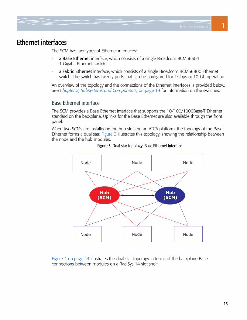
Ethernet interfacesThe SCM has two types of Ethernet interfaces:
a Base Ethernet interface, which consists of a single Broadcom BCM56304 1 Gigabit Ethernet switch.
a Fabric Ethernet interface, which consists of a single Broadcom BCM56800 Ethernet switch. The switch has twenty ports that can be configured for 1Gbps or 10 Gb operation.
An overview of the topology and the connections of the Ethernet interfaces is provided below. See Chapter 2, Subsystems and Components, on page 19 for information on the switches.
Base Ethernet interfaceThe SCM provides a Base Ethernet interface that supports the 10/100/1000Base-T Ethernet standard on the backplane. Uplinks for the Base Ethernet are also available through the front panel.
When two SCMs are installed in the hub slots on an ATCA platform, the topology of the Base Ethernet forms a dual star. Figure 3 illustrates this topology, showing the relationship between the node and the hub modules.
Figure 3. Dual star topology–Base Ethernet Interface
Figure 4 on page 14 illustrates the dual star topology in terms of the backplane Base connections between modules on a RadiSys 14-slot shelf.
Hub(SCM)
Hub(SCM)
Node Node Node
Node Node Node

1 Introduction to the SCM
14
Figure 4. Backplane Base connections to modules on a RadiSys 14-slot shelf
Each Ethernet backplane link consists of four differential signal pairs. Each SCM is installed in a hub slot and acts as a switch that connects to every node (non-SCM) module to form the star topology.
This redundant topology provides an alternate path if one Ethernet path fails, or if one SCM fails. The SCMs connect to each other through a direct Ethernet connection (Base channel 2), which the high-level shelf-management software uses. Traffic through the SCM-to-SCM link is controlled by the Base Ethernet switch, which can also pass user traffic.
For information on the software that manages the Base Ethernet interface, see The Software Guide.
SCMSCMModule
Channel
2 1
Slot 1 Slot 2
(Modulesnot shown
in some slots)
Slot 7 Slot 8
Hub slotsNode slots Node slots
(Modulesnot shown
in some slots)
Module
Channel
2 1
Module
Channel
2 1
Slot 13 Slot 14
UplinksUplinks
Ethernet interface
Module
Channel
2 1

1Network timing subsystem
15
Fabric Ethernet interfaceThe SCM can support either 1 Gbps or 10 Gb Ethernet links for the Fabric interconnect, depending on the node module connections. The full Fabric interface channel is implemented using a 10 Gb XAUI configuration as described in the PICMG 3.1 specification.
The Fabric Ethernet interface also implements a dual star topology similar to the topology of the Base Ethernet interface. However, with the Fabric Ethernet interface there is no direct switch-to-switch link.
Figure 5. Dual star topology–Fabric Ethernet Interface
For information on the software that manages the Fabric Ethernet interface, see The Software Guide.
Network timing subsystem The network timing subsystem (NTS) consists of a circuit block and software. The circuit block provides a centralized timing source for the shelf based on the AdvancedTCA synchronization clock Interface specification. The NTS selects between several internal and external timing references, and provides a phase-locked, highly stable system clock to the platform modules managed by the SCM’s Shelf Manager and the NTS software. See page 38 for information on the circuit block. For details about the software aspects of NTS see the Software Guide.
Hub(SCM)
Hub(SCM)
Node Node Node
Node Node Node

1 Introduction to the SCM
16
COM Express and driveThe SCM includes sites for a COM Express and a SAS or SATA drive. The supported COM Express and the drive, which acts as a peripheral to the COM Express, are available as a build option for the SCM.
When the COM Express and the SAS/SATA drive are implemented on the SCM, they offer processing and storage capabilities well-suited for radio network controller (RNC), media gateway (MGW), information management system (IMS), and Internet protocol television (IPTV) applications.
See Chapter 3, COM Express Subsystem, on page 45 for details on the COM Express subsystem and the SAS/SATA drive.
Installed softwareThe SCM’s Linux-based software includes many features and several management interfaces, including Ethernet switching protocol support, a PICMG-compliant Shelf Manager, a command line interface (CLI), application programming interfaces (APIs), and an SNMP agent. For a complete overview, see the Software Guide.
External connectivityThe SCM provides connectivity for communicating with external equipment through three interfaces:
Front panel interfaces — Front panel interfaces are accessed through each SCM’s faceplate. The connection types are labeled on the faceplate. See page 56 for an illustration of the front panel and a description of all its components, including LEDs and port pinouts.
Backplane interfaces — The backplane is the primary electrical interconnection between the modules in a platform. The Zone 2 connectors of the backplane provide connectivity for the Base, the Fabric, the update channel interfaces, and synchronization clocks. See page 64 for details on the backplane contact assignments and connectors.
Rear transition module interfaces — When installed in a RadiSys shelf, each SCM has an associated rear transition module (RTM) site, which can provide external access to SCM’s signals and connections. See page 71 for descriptions of the RTM’s electrical connections and signal interfaces.

1Connecting to the SCM
17
Connecting to the SCM
Serial connection1. Connect the serial cable to the serial port of the SCM (labeled LMP SER). The appropriate
9-pin D-shell to RJ-45 cable was included in the SCM package.
2. Connect the cable’s other end to the COM1 or COM2 serial port of an external computer (or to a dumb terminal).
3. Start a terminal-emulator application on the external computer. Specify 115,200 baud, 8 data bits, no parity, one stop bit, and no hardware or software flow control. When the terminal emulator is set up and connected, you will receive a login prompt.
Telnet connection1. Connect an Ethernet cable to the SCM’s Ethernet maintenance port (labeled LMP ETH).
2. Connect the cable’s other end to the Ethernet port of a computer that is connected to your network.
3. Configure your computer to a subnet IP address (10.0.0.x, but not 10.0.0.1) and set the netmask to 255.255.255.0.
4. Telnet to IP address 10.0.0.1 (port 23). When the connection is made, you will receive a login prompt.
Logging in to the SCMThe table below shows which user names you can enter to access the command line interface (CLI) or the Linux shell.
The SCM’s default configuration has two main Linux accounts: “root” and “admin.” Neither account is configured with a password by default. Logging in to the SCM as root takes you to the Linux prompt. Logging in as admin brings you to the master CLI.
For information on the software used on the SCM, see the Software Guide. The command line interface commands are described in the CLI Reference.
To access the... ...from the... ...enter:CLI ATCA-2210 login prompt admin and password
Linux shell mcli
Linux shell ATCA-2210 login prompt root and passwordCLI linux-shell

1 Introduction to the SCM
18

19
2SUBSYSTEMS AND COMPONENTS
Figure 6. Detailed block diagram of SCM
2
2
X
PCI-32
43
X
RTM(example)
SCM3
RJ-45
RJ-45
USB
RJ-45Mag
RJ-45Mag
XFP
XFP
XFP
XFP
XFP
SFP
SFP
SFP
SFP
232Buf232Buf
SIO
LPC
COM Expressmodule
SAS/SATAhard drive
SAS/SATA
USB
1 Gb Eth
XAUI toXFI
XAUI toXFI
XAUI toXFI
XAUI toXFI
XAUI toXFI
1 Gb
10 Gb XAUI
Local powerconversion
12 VDC/DC power
converter
2
2
4
24-port Gb+2 port10 Gb
Eth switch
Ser-
Des
TBI
1 Gb SD
10 Gb XAUI
10 Gb XAUI
Dual-bootflash
DDR1SODIMM
PowerQuiccIII
localmanagement
processor
10/100PHY
10/100PHY
10/100-Tx
SerialMII MII
Switch12 V
PCI-EDual 1 Gb
MACSerDes
141 Gb SGMII
COM EType Det
48 V Tyco PIM-200power cond
SFP
SFP
SFP
SFP
SFP
SFP
SFP
SFP
RJ-45
RJ-45
RJ-45
RJ-45
MagI/F
MagI/F
MagI/F
MagI/F
BITS/SSU Clk
BITS/SSU Clk
BITS/SSU Clk
BITS/SSU Clk
Local powerconversion
ID
ID & temp
Buf
Buf
1 Gb SD
1 Gb SD
RTC
EEPROM
12 V
3.3 V
Switch
Switch
I2C
I2C
Zone 3conn
Buf
Buf
12
22
2
PCI-E
SPI
NTM
Mag10/100-Tx
Serial
Updchan 1, 2
Updchan 3, 4
Sync I/F
Updchan 0
Zone 1conn
Zone 2conn
F-linkBase ch2
Nodeslots
ShMCBase ch1
Nodeslots
20-port10 Gb Eth
swith
FEswitch
1
16-portmag
16-portGb EthPHY
I2C EEPROM
ClkInRefClk
1 Gb-Tx
Sync
Clk
ClkInRefClk
SPI 10/100-Tx2
14
14
1
1 Gb-Tx
210 GbXAUI
2IPMB
IPMC(ShMC)
Fuses
Tempsensors
Flash Sel
SPI
SerDes 1Gb SD
4
TBI
Blue = Base EthernetRed = Fabric Ethernet

2 Subsystems and Components
20
The SCM consists of a series of subsystems that work together to provide the network elements required for third generation wireless and wire-line infrastructures. This chapter covers the details of the subsystems that make up the SCM.
Note: The COM Express site subsystem is described in Chapter 3, COM Express Subsystem, on page 45.
Local management processor The local management processor (LMP) is used to manage the Ethernet switches, to manage the network timing subsystem (NTS), and to provide access to the hardware management subsystem.
The LMP provides Ethernet ports, serial communications, an inter-integrated circuit (I2C) controller, a serial peripheral interface (SPI), memory, and peripheral component interconnect (PCI) bus interfaces. Two 1 Gigabit Ethernet ports provide high-speed interfaces to the Base switch and the Fabric switch. A 10/100 Mb Ethernet channel from the LMP is routed to the front panel and provides an interface for switch management. A 10/100 Mb Ethernet channel is routed across the backplane to the redundant SCM. The I2C controller and the SPI buses control on-board peripheral devices. The memory buses provide interfaces to the local synchronous dynamic random access memory (SDRAM), and the boot flash memories. The PCI buses connect to the management ports of the Base and the Fabric Ethernet switches.
The LMP includes the following components:
The block diagram in Figure 7 shows the relationship between the LMP and the SCM.
A PowerQUICC III processor chip with 833 MHz core frequencyA 200-pin SODIMM memory connector for connecting to a memory module with a capacity of 1 Gb DDR SDRAMA redundant pair of 64 MB Spansion flash memory components (128MB total) for PowerQUICC III configuration, Linux operating system boot image, and file systemClock generation circuitryPower good generation circuitryTwo 10/100 Fast Ethernet interfaces to a front panel connector and the update channel
A serial interface to a front panel connectorA serial bus interface to the Intelligent Platform Management Controller (IPMC)An I2C bus interface to the serial EEPROMs, the clock/calendar, and the rear transition module (RTM)A SPI bus to the NTS, the Fast Ethernet switch, and the RTMTwo peripheral component interconnect (PCI) bus configuration interfaces to the Base and the Fabric Ethernet switches1 Gb Ethernet interface to the Base switch1 Gb Ethernet interface to the Fabric switch

2Local management processor
21
Figure 7. Local management processor with SCM
JTAG/COP
Serial port to IPMC
UART1
UART0
DRAM bus
10/100Base-TEthernet
Localmanagement
processor
I2C bus
Front panelconsole port
COP debugheader
10/100Base-TEthernet
Update channel link
Front panelmgmt port
I GB DDR1SDRAM
64MB FlashROM 0
64MB FlashROM 1
Local bus
PCI bus 0
Fabric interfaceswitch
PCI bus 1
SPI bus
Clock/calendar
UserEEPROM
MACaddressEEPROM
RTM
NetworkTimingmodule
RTM
Base interfaceswitch
FastEthernetswitch
MDIO
Base interfaceswitch
10/100/1000 MBEthernet
10/100/1000 MBEthernet

2 Subsystems and Components
22
PowerQUICC III processorThe LMP is based on a PowerQUICC III processor. The PowerQUICC III LMP is packaged in a 783-pin ball grid array and is highly integrated with an embedded e500 core; integrated instruction and data caches, a system interface unit, and an integrated reduced instruction set computer-based (RISC) communications processor.
The PowerQUICC III LMP has the following characteristics:
The PowerQUICC III processor chip incorporates the following elements:
ProcessorCore Freq. (MHz)
PCI Bus Freq. (MHz)
SYSCLK Freq. (MHz) VDD/Core
I Cache(Kbytes)
DCache(Kbytes)
Processor Version
MPC8541 833 66 66 3.3V/1.2V 32 32 0x0080
CPU with e5000 core that implements Book E 32-bit architecture256KB on-chip memoryDDR memory controllerProgrammable interrupt controller (PIC) compliant with OpenPIC architectureLocal Bus Controller (LBC), which connects to the two 64MB flash components Two PCI bus controllers used to configure the Base and the Fabric switchesI2C controller providing access to the SDRAM module, two serial EEPROMs, the clock/calendar, and devices on the RTMTwo UART interfaces for:
Serial console port routed through front panel Serial port providing link between the PowerQUICC III and the on-board IPMC
Two 10/100Base-T Ethernet interfaces (Fast Ethernet)
One interface is used for management and maintenance purposes One interface is used for connecting to the redundant SCM through the update channel
Two 10/100/1000 interfaces configured as ten-bit interfaces (TBI) and linked to a serializer/deserializer (SerDes). The interfaces are connected to the Base Ethernet switch and Fabric Ethernet switch as alternate ports to the PCI bus.
Serial management data input/output (MDIO) port for managing the physical layer devices (PHYs) on the 10/100Base-T interfacesSPI controller providing a four-wire serial bus for accessing the NTS, the 10/100Base-T Ethernet switch, and devices on the RTMEEPROM used to store media access control (MAC) addresses for Ethernet portsEEPROM used for storing user-defined informationClock/calendar to keep a running time and date. Includes lithium battery to maintain timekeeping when power is not available to the SCM.General purpose input/output (I/O) signals to and from various functions on the SCM for control and statusSynchronous dynamic random access memory (SDRAM) interface for the small outline dual in-line memory module (SODIMM).Two Spansion flash memory devices used as a redundant set of 64MB flash stores.Reads I/O bus information on the SCM version and revision historyIntegrated reset logic

2Local management processor
23
Controller and device assignmentsThe following sections show the assignments for the controllers and the devices that make up the PowerQuicc III LMP.
Communications controller assignmentsThe PowerQUICC III communication controller functions as they pertain to the SCM are mapped out in the following table.
Local bus controller The 32-bit local bus controller on the PowerQuicc III maps to the two 64 MB flash components using the following assignments.
Table 1. Communication controller assignments
PowerQUICC III communication controller function SCM functionPCI0 Base Ethernet switchPCI1 Fabric Ethernet switchTSEC1 (TBI Ethernet) Gb link to Base Ethernet switchTSEC2 (TBI Ethernet) Gb link to Fabric Ethernet switchUART0 Front panel RS232 serial console portUART1 IPMC serial interface I2C SMBus to SDRAM, EEPROM, clock/calendarCPM:FCC0 10/1000Base-T Ethernet port (front panel) CPM:FCC1 10/100Base-T Ethernet port (update channel) CPM:SPI NTS, Fast Ethernet switch, RTM interfaceCPM:I2C Not used
Table 2. Local bus controller memory map assignments
Chip select Selected deviceLCS0# Local bus: Flash memory 0/1(depending on FLSH_SEL from IPMC)LCS1# Local bus: Flash memory 1/0(depending on FLSH_SEL from IPMC)LCS2# Local bus: Flash memory 0LCS3# Local bus: Flash memory 1LCS4# Port 80: Debug checkpoint display (write-only using LCS4# signal as write strobe)LCS5# SFP status (read-only)LCS6# not usedLCS7# not used
2 Subsystems and Components
24
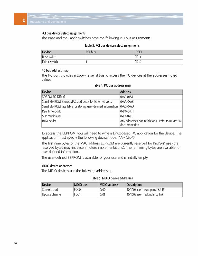
PCI bus device select assignmentsThe Base and the Fabric switches have the following PCI bus assignments.
I2C bus address mapThe I2C port provides a two-wire serial bus to access the I2C devices at the addresses noted below.
To access the EEPROM, you will need to write a Linux-based I2C application for the device. The application must specify the following device node: /dev/i2c/0
The first nine bytes of the MAC address EEPROM are currently reserved for RadiSys’ use (the reserved bytes may increase in future implementations). The remaining bytes are available for user-defined information.
The user-defined EEPROM is available for your use and is initially empty.
MDIO device addressesThe MDIO devices use the following addresses.
Table 3. PCI bus device select assignments
Device PCI bus IDSELBase switch 0 AD11Fabric switch 1 AD12
Table 4. I2C bus address map
Device AddressSDRAM SO DIMM 0xA0-0xA1Serial EEPROM: stores MAC addresses for Ethernet ports 0xAA-0xABSerial EEPROM: available for storing user-defined information 0xAC-0xADReal time clock 0xD0-0xD1SFP multiplexer 0xEA-0xEBRTM device Any addresses not in this table. Refer to RTM/SPM
documentation.
Table 5. MDIO device addresses
Device MDIO bus MDIO address DescriptionConsole port FCC0 0x00 10/100Base-T front panel RJ-45Update channel FCC1 0x01 10/100Base-T redundancy link

2Flash memory layout
25
SPI device selection map The SPI devices use the following addresses.
Flash memory layoutFigure 8 shows the layout of the flash memory devices used in the SCM. Each flash memory device consists of 64MB flash parts. The part of the flash memory selected by the IPMC as the boot device is located in the memory map at address FC000000h. Flash part 0 is the primary boot device and is located at address E0000000h. Flash part 1 is the secondary boot device and is located at address E4000000h.
Figure 8. Flash device memory layout
Table 6. SPI device selection map
Device Device selection AddressNetwork timing subsystem SPI:NTS_SEL~ PD24FE switch SPI:FES_SEL~ PD23LED controller SPI:LED_SEL~ PD25RTM BITS element SPI:RTM_SEL~ Defined on RTM, enabled by PD22.
Unused/misc. registers
Flash part 0primary boot
E000 0000h
E800 0000h
F000 0000h
F800 0000h
FFFF FFFFh
64MB
64MB
128MB
64MB
64MB
Flash part 1secondary boot
Flash partselected by IPMCas the boot device
FC00 0000h
128MBUnused
Unused
E400 0000h

2 Subsystems and Components
26
Figure 9 shows the layout of the 128 MB partition of each flash memory device used in the SCM.
Figure 9. Flash memory device map
The JFFS is used to store configuration, log, and other non-volatile files. The JFFS image comes from the active part of the memory. The address of the JFFS image is FC000000.
ubootU-Boot
Kernel andfile system image
JFFS Image(Unused in 2nd Part)
JFFS image
512KB
48MB
15.5MB
Lowermemory

2Flash memory layout
27
Figure 10 shows the layout of memory technology device (MTD) partitions used in the SCM. These partitions are used to load items from the flash and also to program the flash memory.
Figure 10. Flash memory device partitions
mtd3
JFFS2
mtd4
Primary kerneland file system
Primary U-Boot
Secondary U-Boot
mtd6
mtd7
mtd0
mtd1
E000 0000h
E400 0000h
E800 0000h
mtd2
Secondary kerneland file system
mtd5JFFS2
2 Subsystems and Components
28
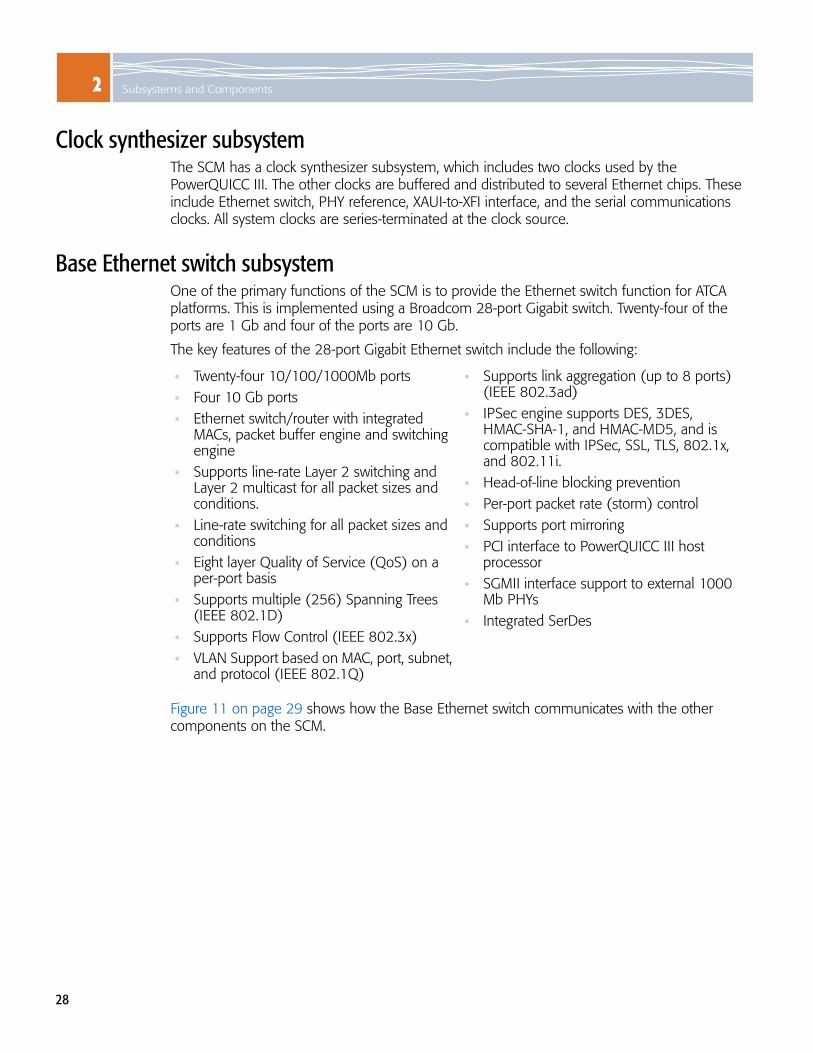
Clock synthesizer subsystemThe SCM has a clock synthesizer subsystem, which includes two clocks used by the PowerQUICC III. The other clocks are buffered and distributed to several Ethernet chips. These include Ethernet switch, PHY reference, XAUI-to-XFI interface, and the serial communications clocks. All system clocks are series-terminated at the clock source.
Base Ethernet switch subsystem One of the primary functions of the SCM is to provide the Ethernet switch function for ATCA platforms. This is implemented using a Broadcom 28-port Gigabit switch. Twenty-four of the ports are 1 Gb and four of the ports are 10 Gb.
The key features of the 28-port Gigabit Ethernet switch include the following:
Figure 11 on page 29 shows how the Base Ethernet switch communicates with the other components on the SCM.
Twenty-four 10/100/1000Mb ports Four 10 Gb portsEthernet switch/router with integrated MACs, packet buffer engine and switching engineSupports line-rate Layer 2 switching and Layer 2 multicast for all packet sizes and conditions.Line-rate switching for all packet sizes and conditionsEight layer Quality of Service (QoS) on a per-port basisSupports multiple (256) Spanning Trees (IEEE 802.1D)Supports Flow Control (IEEE 802.3x)VLAN Support based on MAC, port, subnet, and protocol (IEEE 802.1Q)
Supports link aggregation (up to 8 ports) (IEEE 802.3ad)IPSec engine supports DES, 3DES, HMAC-SHA-1, and HMAC-MD5, and is compatible with IPSec, SSL, TLS, 802.1x, and 802.11i.Head-of-line blocking preventionPer-port packet rate (storm) controlSupports port mirroring PCI interface to PowerQUICC III host processorSGMII interface support to external 1000 Mb PHYsIntegrated SerDes

2Base Ethernet switch subsystem
29
Figure 11. Base Ethernet switch
Port 0Port 1Port 2Port 3
Port 7
Port 4Port 5Port 6
Frontpanel
Port 23
Port 25
BCh3
BCh7
BCh4
BCh5
BCh8
BCh9
BCh6
BCh10BCh11
BCh14
BCh12
BCh13
ShMC1
BCh16BCh15
Backplane
Base Ethernetswitch
Dual GbEmagnetics
PowerQUICC III
PCI Bus 1
Port 8Port 9
Port 10Port 11
Port 15
Port 12Port 13Port 14
Port 16
Port 17
Quad GbEPHY
GPIO Reset
PCI Bus
TSEC1
TBI GbSerDes
COM Express
PCI-Express
GbE MACSerDes
XAUI to XFI XFP
Zone 3conn
FE switchw/mags
ShMC2
BCh2
RTM
Frontpanel
Quad GbESFP
BCh1
Port 27
Port 26
Port 24
Port 21Port 20Port 19Port 18
Port 22
Quad GbEPHY
Quad GbEPHY
Quad GbEPHY Dual GbE
magnetics
Dual GbEmagneticsDual GbEmagnetics
Dual GbEmagneticsDual GbEmagnetics
Dual GbEmagneticsDual GbEmagnetics

2 Subsystems and Components
30
Port mapping Table 7. Base Ethernet port mapping
Port # PHY/Port MDIO interface address Port destination IPMI hardware
address Logical slot
0 0 / 0 0x00 FE Switch (Shelf Manager) N/A N/A1 0 / 1 0x01 Base channel 2 (link to redundant SCM) 0x41 / 42 1 / 22 0 / 2 0x02 Base channel 3 0x43 33 0 / 3 0x03 Base channel 4 0x44 44 1 / 2 0x06 Base channel 5 0x45 55 1 / 3 0x07 Base channel 6 0x46 66 1 / 0 0x04 Base channel 7 0x47 77 1 / 1 0x05 Base channel 8 0x48 88 2 / 2 0x0A Base channel 9 0x49 99 2 / 3 0x0B Base channel 10 0x4A 1010 2 / 0 0x08 Base channel 11 0x4B 1111 2 / 1 0x09 Base channel 12 0x4C 1212 3 / 2 0x0E Base channel 13 0x4D 1313 3 / 3 0x0F Base channel 14 0x4E 1414 SFP interface to RTM 0x0C or N/A SFP3 on the RTM N/A N/A15 SFP interface to RTM 0x0D or N/A SFP4 on the RTM N/A N/A16 SerDes N/A COM Express N/A N/A17 SFP interface to RTM N/A SFP1 on the RTM N/A N/A18 SFP interface N/A Front panel 1/6: 1G optical or 10/100 Mbit
copper N/A N/A
19 SFP interface N/A Front panel 1/7: 1G optical or 10/100 Mbit copper
N/A N/A
20 SFP interface N/A Front panel 1/8: 1G optical or 10/100 Mbit copper
N/A N/A
21 SFP interface N/A Front panel 1/9: 1G optical or 10/100 Mbit copper
N/A N/A
22 SFP interface to RTM N/A SFP2 on the RTM N/A N/A23 SerDes N/A PowerQUICC III N/A N/AX0 XFP interface 0x10 Front panel 1/5: XFP N/A N/AX1 XFP interface TBD RTM XAUI N/A N/AX2 XFP interface N/A Not used N/A N/AX3 XFP interface TBD RTM XAUI N/A N/A

2Base Ethernet switch subsystem
31
ConfigurationThe switch has built in media access controllers (MACs) for each port that interface to the external physical layer devices (PHYs).
The 1 Gigabit Ethernet ports can each be configured to operate in:Serial Gigabit Media Independent Interface (SGMII) mode, which has Gigabit Ethernet ports going to the backplane, front panel RJ-45 ports, and RTM. Serializer/deserializer (SerDes) modes, which support Gigabit Ethernet ports going to optical SFP modules, 10/100/1000 Mbit ports going to copper SFP modules, or internal links. One port to the COM Express site as 1 Gb SerDes
The 10 Gigabit Ethernet ports are configured to operate in 10 Gigabit attachment unit interface (XAUI) mode, with ports routed to Zone 3 and the front panel XFP ports.
10/100/1000Base-T Gigabit Ethernet portsSixteen Gigabit Ethernet PHYs provide 10/100/1000Base-T connectivity to the backplane and the Fast Ethernet (FE) switch. All of the 1000Base-T ports use a Gigabit PHY channel along with Gigabit Ethernet transformers to couple to the backplane.
12 ports to backplane node slots, depending on the board configuration.
One port to an FE switch, allowing two FE connections to an external Shelf Manager (if present) through Base channel 1.
One port to the Base interface of a redundant SCM (if present) through Base channel 2.
SerDes Gigabit Ethernet portsSix ports are configured as serializer/deserializer (SerDes) ports. Two of the SerDes ports go to the on-board LMP and the COM Express site. Four of the SerDes ports are directed to SFP sockets on the SCM front panel.
10 Gigabit Ethernet portsThree 10 Gb Base Ethernet ports provide external access on the front and the rear faceplates.
1 XFP port on the front panel, XFI signaling converted from XAUI
2 XAUI signaling to RTM
The XFP 10 Gb connector uses XFI signaling, composed of single transmit and receive 10 Gb differential pairs. A XAUI-to-XFI interface chip converts the signaling from the XAUI signals (connected to the switch) to XFI signals (connected to the XFP port) at the front panel.

2 Subsystems and Components
32
Fast Ethernet switchA 5-port 10/100Base-T Ethernet switch connects one Base interface port to one or two off-board Shelf Managers through Base channel 1.
The Fast Ethernet (FE) switch is managed by the PowerQUICC III using the SPI port.
Port status LEDsThis table describes the LEDs specific to the Base Ethernet.
Table 8. Fast Ethernet switch port mapping
Port # Port destination Port states1 Base interface Port 1 should always be enabled.2 Base channel 1a Ports 2 and 3 may be enabled or disabled (together), depending on SCM
configuration for Base connectivity to an off-board Shelf Manager.3 Base channel 1b 4 Not used Ports 4 and 5 are not used, and should be disabled.5 Not used
Table 9. Base Ethernet port status LEDS
Port LED and possible states1 Gb optical or 10/100 Mbit copper SFP portsEach Base Ethernet SFP port on the front panel or on the RTM has two LEDs
1 green link status LEDGreen – link establishedBlinking green – link activityOff – link fail or port is disabled
1 green port status LED Green – port is enabled Off – port is disabled
10 Gb XFP portsEach Base Ethernet XFP port on the front panel or on the RTM has two associated LEDs.
1 green link/activity status LEDGreen – link establishedBlinking green – link activityOff – link fail or port is disabled
1 green port status LED Green – port is enabled Off – port is disabled

2Fabric Ethernet switch subsystem
33
Fabric Ethernet switch subsystem The SCM provides a 10 Gb Fabric Ethernet connection to 12 or 14 node slots (depending on the board configuration) based on AdvancedTCA 3.1. Four ports of the Fabric interface are also available on the front panel and three ports are routed to the RTM through the Zone 3 area.
The Fabric interface is implemented using a Broadcom 20-port 10 Gb Ethernet switch. The backplane ports use XAUI, made up of four lanes (Tx and Rx differential pairs) operating at 3.125 Gb. The front panel uses XFI on an XFP connector, converted from the XAUI signaling on the switch ports by a XAUI-to-XFI transceiver.
The Fabric Interface connects:
Note that there is no direct Base-to-Fabric connection on an SCM and no Fabric-to-Fabric connection between the two SCMs.
Figure 12 is a block diagram showing how the Fabric Ethernet switch communicates with the rest of the SCM.
Node slots as 10 Gb XAUI or 1 Gb SerDesFront panel XFP connector ports as 10 Gb XFI1 or 3 ports (depending on the board configuration) to the RTM as 10 Gb XAUI or 1 Gb SerDes
One port to the COM Express site as 1 Gb SerDes The LMP on PCI Bus 2

2 Subsystems and Components
34
Figure 12. Fabric Ethernet switch
Port 0Port 1Port 2Port 3
Port 7
Port 4Port 5Port 6
Port 18Port 16
Port 17
FCh2
FCh6
FCh3FCh4
FCh7FCh8
FCh5
FCh9FCh10
FCh13
FCh11FCh12
FCh15FCh14
Backplane
PowerQUICC III
PCI bus 2
Port 8Port 9
Port 10Port 11Port 12Port 13
Port 19
GPIO Reset
PCI bus
TSEC2
COM Express
PCI-Express
GbE MACSerDes
XFP
Frontpanel
XFP
Port 15 XFP
Port 14 XAUI toXFI
XFP
RTM
Fabric Ethernet
XAUI toXFI
XAUI toXFI
XAUI toXFI

2Fabric Ethernet switch subsystem
35
Port mappingTable 10. Fabric Ethernet port mapping
Port # PHY/Port MDIO interface address Port destination IPMI hardware address Logical slot
0 XFP interface N/A Fabric channel 2 0x43 31 XFP interface N/A Fabric channel 3 0x44 42 XFP interface N/A Fabric channel 4 0x45 53 XFP interface N/A Fabric channel 5 0x46 64 XFP interface N/A Fabric channel 6 0x47 75 XFP interface N/A Fabric channel 7 0x48 86 XFP interface N/A Fabric channel 8 0x49 97 XFP interface N/A Fabric channel 9 0x4A 108 XFP interface N/A Fabric channel 10 0x4B 119 XFP interface N/A Fabric channel 11 0x4C 1210 XFP interface N/A Fabric channel 12 0x4D 1311 XFP interface N/A Fabric channel 13 0x4E 1412 XFP interface defined by RTM RTM N/A N/A13 XFP interface defined by RTM RTM N/A N/A14 XFP interface 0x10 Front panel XFP 1/1 N/A N/A15 XFP interface 0x11 Front panel XFP 1/2 N/A N/A16 XFP interface 0x12 Front panel XFP 1/3 N/A N/A17 XFP interface 0x13 Front panel XFP 1/4 N/A N/A18 SerDes N/A COM Express N/A N/A19 XAUI interface N/A RTM N/A N/A

2 Subsystems and Components
36
ConfigurationThe Fabric interface on the SCM is a managed 10 Gb Ethernet switch with the following features:
Switch configuration via the PowerQUICC III PCI busTransmit (Tx) port disable based on E-Key port state
The Fabric Ethernet configuration port is connected to the PowerQUICC III through PCI bus 2, a 32-bits wide bus operating at 66MHz.
10 Gigabit Ethernet portsFor the standard SCM configuration, twenty 10 Gb Fabric Interface ports are available on the Fabric Ethernet:
Twelve ports provide direct XAUI node-slot backplane connections and can be configured as 10 Gb XAUI or 1 Gb SerDes.Four XFP ports on the front panel. Each XFP 10 Gb connector uses XFI signaling, composed of single transmit and receive 10 Gb differential pairs. A XAUI to XFI interface chip converts the signaling from the XAUI signals at each switch port to the XFI signals on the XFP connector.Three ports routed to the RTM, which can be configured as 10 Gb XAUI or 1 Gb SerDes.
One port is configured for 1Gb operation and provides a connection to the COM Express site.
XFP port LEDsThis table describes the LEDs specific to the Fabric Ethernet. The LEDs are controlled by the Fabric Ethernet switch through a serial LED bus.
Table 11. XFP port LEDs
Port LED and possible statesXFP port LEDsEach of the Fabric Ethernet XFP ports on the front panel or the RTM has two LEDs.
1 green link/activity status LEDGreen – link establishedBlinking green – transmit/receive activityOff – no link or port disabled
1 green port status LED Green – port is enabled Off – port is disabled
2LED controller interface subsystem
37
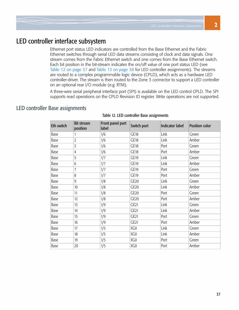
LED controller interface subsystem Ethernet port status LED indicators are controlled from the Base Ethernet and the Fabric Ethernet switches through serial LED data streams consisting of clock and data signals. One stream comes from the Fabric Ethernet switch and one comes from the Base Ethernet switch. Each bit position in the bit-stream indicates the on/off value of one port status LED (see Table 12 on page 37 and Table 13 on page 38 for LED controller assignments). The streams are routed to a complex programmable logic device (CPLD), which acts as a hardware LED controller-driver. The stream is then routed to the Zone 3 connector to support a LED controller on an optional rear I/O module (e.g. RTM).
A three-wire serial peripheral interface port (SPI) is available on the LED control CPLD. The SPI supports read operations on the CPLD Revision ID register. Write operations are not supported.
LED controller Base assignments Table 12. LED controller Base assignments
Eth switchBit stream position
Front panel port label Switch port Indicator label Position color
Base 1 1/6 GE18 Link GreenBase 2 1/6 GE18 Link AmberBase 3 1/6 GE18 Port GreenBase 4 1/6 GE18 Port AmberBase 5 1/7 GE19 Link GreenBase 6 1/7 GE19 Link AmberBase 7 1/7 GE19 Port GreenBase 8 1/7 GE19 Port AmberBase 9 1/8 GE20 Link GreenBase 10 1/8 GE20 Link AmberBase 11 1/8 GE20 Port GreenBase 12 1/8 GE20 Port AmberBase 13 1/9 GE21 Link GreenBase 14 1/9 GE21 Link AmberBase 15 1/9 GE21 Port GreenBase 16 1/9 GE21 Port AmberBase 17 1/5 XG0 Link GreenBase 18 1/5 XG0 Link AmberBase 19 1/5 XG0 Port GreenBase 20 1/5 XG0 Port Amber

2 Subsystems and Components
38
LED controller Fabric assignments
Network timing subsystemThe NTS is the centralized system timing function provided by the SCM. The timing function is based on the backplane synchronization clock interface described in the AdvancedTCA Base Specification.
The list below and Figure 13 provide an overview of the operation of the NTS.
Table 13. LED controller Fabric assignments
Eth switch Bit stream position
Front panel port label Switch port Indicator label Position color
Fabric 1 1/1 XG15 Link GreenFabric 2 1/1 XG15 Link AmberFabric 3 1/1 XG15 Port GreenFabric 4 1/1 XG15 Port AmberFabric 5 1/2 XG16 Link GreenFabric 6 1/2 XG16 Link AmberFabric 7 1/2 XG16 Port GreenFabric 8 1/2 XG16 Port AmberFabric 9 1/3 XG17 Link GreenFabric 10 1/3 XG17 Link AmberFabric 11 1/3 XG17 Port GreenFabric 12 1/3 XG17 Port AmberFabric 13 1/4 XG18 Link GreenFabric 14 1/4 XG18 Link AmberFabric 15 1/4 XG18 Port GreenFabric 16 1/4 XG18 Port Amber
Provides a Synchronous Equipment Timing Source (SETS) for all shelf node modulesAccepts system timing from up to four (redundant) Building Integrated Timing Source (BITS) frames, and generates up to four framed synchronization signals for shelf-to-shelf chaining (if supported by the RTM)Accepts and generates Synchronization Supply Unit (SSU) frames per ITU-T Recommendation G.812 (if supported by the RTM)Accepts timing references from backplane node module synchronization clocks (CLK3-A and CLK3-B)
Generates 8 KHz and 19.44 MHz synchronization clocks on backplane (CLK1-A/B and CLK2-A/B, respectively) Generates 8 KHz, 2.048 MHz, 1.544 Mhz, and 19.44 Mhz synchronization clocks for the RTMCan provide automatic or manual hitless input switchover on loss of input, if configured using input priority levelsProvides automatic hitless protection of the system clock when operating with a redundant SCM

2Network timing subsystem
39
Figure 13. Network timing subsystem
The NTS can select reference timing sources from the synchronization bus, the RTM, or the update channel and be configured with priority levels for each input. By monitoring each input, the NTS can automatically switch between valid sources based on those priorities. Information on configuring the different timing sources is covered in the Software Guide.
Synchronization clock and update channel buffer enables The PowerQUICC III can enable or disable the clock buffers to the synchronization clock and update channel outputs. Permission to drive these signals comes from the Shelf Manager through the IPMC, as part of E-Keying.
UPDCH3Rx
Networktiming
subsystem
RTM (Illustration)
SCM
6.48 MHZ OUT
BIT CLK OUT
EXT CLK IN 1
EXT CLK IN 2
EXT CLK IN 3
EXT CLK IN 4
12.8MHzTCX0
12.8MHz0CX0
12.8MHzX0
PowerQUICC III
SPI
GPIO
I7
I8
I10
I9
T02
T03
SPI
CSB
RefClk
T04
T05
T011
T01
Sync2k
I11
19.44 MHz
8.KHz
19.44 MHz
2 KHz OUT
2 KHz IN
6.48 MHZ INI3
I4
CLK3-B
CLK3-A
UPDCH4Rx
CLK2-B
UPDCH4Tx
UPDCH3Tx
CLK2-A
CLK1-B
CLK1-A
Framer/Deframer
Framer/Deframer
Framer/Deframer
Framer/Deframer
BITS/SSU-4
REF-4
BITS/SSU-3
REF-3
BITS/SSU-2
REF-2
BITS/SSU-1
REF-1

2 Subsystems and Components
40
Hardware management subsystem The function and operation of the SCM hardware management subsystem is controlled by the Intelligent Platform Management Controller (IPMC). The hardware management subsystem is the collection of IPMCs and sensors on the installed modules and field replaceable units (FRUs), and the communication between these devices and the Shelf Manager. The SCM’s IPMC manages the commands and the data portion of this subsystem.
The IPMC has the following features:
Figure 14 on page 41 shows how the IPMC communicates with other subsystems like the LMP and the RTM.
Dual I2C interface to backplane intelligent platform management bus (IPMB) with programmable pull-upsSerial interfaces to LMP and COM Express siteI2C interfaces to I/O expander, field-programmable gate array (FPGA), temperature sensors, voltage sensors, and RTMSystem event log (SEL) capabilities
Remote executable flash and micro-controller software update supportElectronic keying (E-Keying) support for Base interface, Fabric interface, synchronization clocks, and update channelsRemote micro-controller software update support

2Hardware management subsystem
41
Figure 14. IPMC control interface to payload and RTM
IPMC
48 V DC/DC
+12V
LMP
FlipflopGPIO5
Powerswitch
Powerswitch
-48 V
COM Express
+12V +3.3V
+3.3V_CE+12V_CE
Powerswitch
1 GbEEna
CE_GBE1
Update channel
COM0_TXCOM0_RX
IRQ 0SRESET#BUF_MRESET#PORESET#FLSH_SEL
PL-RST#0
CE_UC_ENA
CECOM1_RXCECOM1_TXCOME:RESET#COM_E_TYPE0COM_E_TYPE1COM_E_TYPE2COM_E_PRST~
COME:PWR_FAIL~
COME:PWR_ENA~
IPMC:I2C_SDAIPMC:I2C_SCLRTM_ENA~RTM:HOTSWAP
RTM_RST~RTM_EJECT_IN~RTM_PRESENT~RTM_INTR~RTM:+3.3V_FAIL~RTM_+3.3V_ENA~RTM:+12V_FAIL~RTM_+12V_ENA~
IPMC:MSG_FLAG_STBIPMC:MSG_FLAG
IPMC:MSG_FLAG_CLR
+3.3V_IPMC
PAYLOAD_PWR#
+12V_RTM
+3.3V_RTM
RTM
+12V +3.3V_IPMI

2 Subsystems and Components
42
Non-volatile random access memoryThe non-volatile random access memory (NVRAM) in the IPMC on the SCM is a 64 KB device. The NVRAM stores the following types of information about the field replaceable units (FRUs):
The SCM acting as the active Shelf Manager, retrieves this information from the IPMC and stores the information. To provide redundancy, the active Shelf Manager also sends the FRU information to the inactive Shelf Manager, which also stores the information. This information is recorded in the system event log (SEL) to monitor system events.
IPMC watchdog timerThe IPMC entity includes a hardware watchdog timer. Once the watchdog is activated, the IPMC must strobe it in order to keep it from timing out. If a firmware or a hardware problem on the IPMC causes it to stop strobing the watchdog timer, the IPMC is automatically isolated from the IPMB. This isolation of the IPMC keeps the IPMI buses functional for the remaining IPMC devices. A two-pin header can be used to disable the watchdog timer during debug.
Serial numberPart numberManufacturerDate and time of manufacture
Product nameFRU capabilitiesPoint to point connectivity records for modules that plug into the backplane, which is used for E-Keying

2Power supplies
43
Power suppliesInformation on the SCM’s power consumption and emissions is provided in Specifications on page 91.
Power input module (PIM)The SCM uses a power input module (PIM), which provides input conditioning of the -48V backplane power feeds. This module is between the input protection fuses and the main 48V to 12V DC/DC converter. Features of the PIM include:
-48V to 12V primary voltage conversion A DC/DC converter is used to generate 12V for the SCM. This power supply provides up to 18 Amps of current to power the SCM payload and RTM. The RTM power buses are switched from this supply through integrated FET switches, controlled by the IPMC. Output voltage tolerance: ±5%. The DC/DC is switched on and off through an optically isolated control signal from the IPMC.
Power converters The following non-isolated supplies are generated from the 12V intermediate supply by switching regulators:
Inrush current limit protectionIntegrated conducted noise filterIsolated auxiliary 3.3V power for IPMI circuitORing field effect transistors (FETs) on A and B -48V feedsA/B feed loss alarm
Hot-swap controlGlitch hold-up circuit based on external capacitor and 72V charging circuitInput under voltage and over voltage protectionOver current and thermal protection
5.0 V DC for components such as the hard drive and the XFP modules. 3.3 V DC for components such as the hard drive, the XFP modules, and the NTS block. 2.5 V DC for use components such as the PowerQUICC III, the DRAM, the 1 Gb SerDes, and the FE switch. 1.8 V DC for components such as the XFP modules, the XAUI-to-XFI interfaces, the PCI Express 1 Gb controllers.
1.25 V DDR for the DDR DRAM module. 1.25 V DC for the Base and the Fabric Ethernet switches. 1.2 V DC for the PowerQUICC III, Gigabit Ethernet Quad PHYs, and the XAUI-XFI interfaces. 1.1 V DC for use by the PCI Express 1 Gb controllers. 1.0 V DC for the 10 Gb Ethernet switch.

2 Subsystems and Components
44

45
3COM EXPRESS SUBSYSTEM
The SCM has sites for an optional COM Express and a peripheral SAS or SATA drive, which are available as an SCM build option.
The COM Express is an embedded, server-oriented Computer on Module (COM) mezzanine board processor. The SCM supports the Procelerant™ CE3100 COM Express, which is a type 3 module compliant with the PICMG® COM.0 R1.0 COM Express™ Module Base Specification. The COM Express is a “basic” module with a form-factor size of 95-125 mm (3.74''-4.92''). The thickness of the PCB is 2.4 mm (0.9'') with a tolerance of ± 0.24 mm (0.1'').
The peripheral drive site supports a 2.5 inch SAS or SATA drive and its interfaces are directly connected to the COM Express, providing flexible storage options.
SCMs with this build option of the COM Express and SAS/SATA drive ship with a factory-installed basic software package. Once the SCM is installed, and depending on your organization’s needs, you may choose to change the BIOS settings or install an operating system and drivers.
The COM Express supported by the SCM has the following features:
Figure 15 on page 46 shows a block diagram and of the COM Express and Figure 16 on page 47 shows the subsystems connections. Figure 17 on page 47shows the key components on a COM Express.
An Intel® 1.5 GHz Core™ 2 Duo L7400 CPUAn Intel 3100 chipset containing the functionality of a memory controller hub (MCH) and an I/O controller hub (ICH) in a single integrated chipAn ECC SDRAM memory module supporting DDR-400 memory Dual Gigabit Ethernet on a single-lane PCI Express link to provide a connection to the Base and the Fabric Ethernet switches of the SCM, with a limit of 2 gigabits per second in each direction A PCI Express lane is routed to the RTM through Zone 3; the lane is not used on the SPMFront panel ports including a serial port, an Ethernet port, and a USB port
A 10/100/1000Base-T Ethernet port routed through Update channel to redundant COM Express on second SCMSAS/SATA drive supportA firmware hub (FWH) with BIOS firmware code stored in a 1 MB flash memory chip12 V module power supported, with a maximum power consumption of 26 watts IPMC-controlled operation of the module including the initial detection of the module type, power enable, reset control, and update channel E-Key controlReset control independent from the LMP reset. The reset is dependent on the software installed on the COM Express

3 COM Express Subsystem
46
Figure 15. COM Express block diagram
CO
M E
xpre
ss b
oard
-to-b
oard
inte
rcon
nect
or
Intel 3100 chipsetIMCH+IICH
Dual-portGigabitEthernet
GbE
GbEPCIEx4
UART to I2Ccontroller
SMBus
I2CUART
SAS/SATA
PCI-Ex4
Four SAS/SATA
FlashROM NVSRAM
Memorysocket
supportingDDR2-400
DDR2
RTC
UART0/BIOS recovery/
clear CMOS
CPU ITP
FWH
LPC
Four PCI-Ex1Four USB 2.0
Four GPOsFour GPIs
PCI
LPCFSB

3
47
Figure 16. COM Express site connections
Figure 17. COM Express components
BaseEthernet
switch
MAGRJ-45
BUFRS232
SuperI/O
LPC
ETH0ETH1
IPMC
Type +present
Reset
USBUSB SAS/SATA
PCI-E
CTL
PWR
PWRDAT SAS/
SATAdrive
Dual 1 GbMAC
PWR ENA
UC ENA
Updatechannel
Zone 3
PWR 1Gb1Gb
COM1COM2
Port 16 Port 18
0 1RST
RJ-45
MAG
COMExpressmodule
PCI-EPCI-E
FabricEthernet
switch
CPU
DDR2 SO-RDIMMmemory socket
Firmware hub (FWH)
SAS chip(build option)
Intel 3100 chipsetIMCH + IICH
Gigabit Ethernetcontroller
PCI Express x1/x4 switch
3 COM Express Subsystem
48
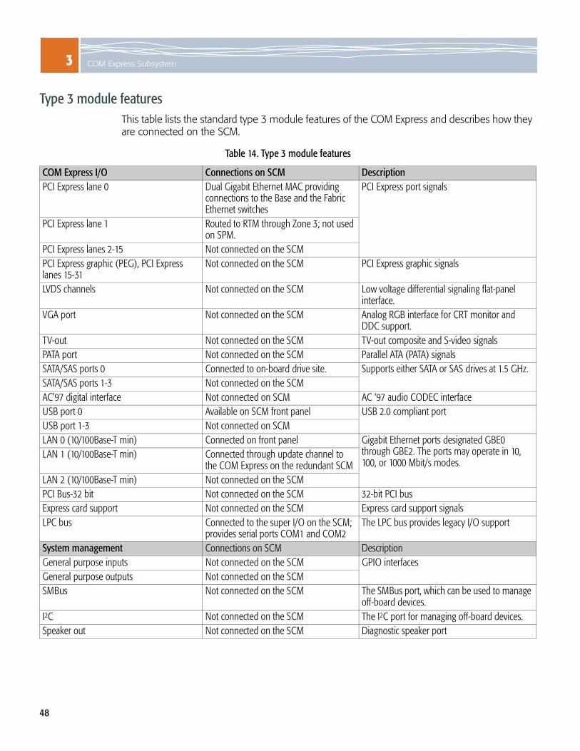
Type 3 module featuresThis table lists the standard type 3 module features of the COM Express and describes how they are connected on the SCM.
Table 14. Type 3 module features
COM Express I/O Connections on SCM DescriptionPCI Express lane 0 Dual Gigabit Ethernet MAC providing
connections to the Base and the Fabric Ethernet switches
PCI Express port signals
PCI Express lane 1 Routed to RTM through Zone 3; not used on SPM.
PCI Express lanes 2-15 Not connected on the SCMPCI Express graphic (PEG), PCI Express lanes 15-31
Not connected on the SCM PCI Express graphic signals
LVDS channels Not connected on the SCM Low voltage differential signaling flat-panel interface.
VGA port Not connected on the SCM Analog RGB interface for CRT monitor and DDC support.
TV-out Not connected on the SCM TV-out composite and S-video signalsPATA port Not connected on the SCM Parallel ATA (PATA) signalsSATA/SAS ports 0 Connected to on-board drive site. Supports either SATA or SAS drives at 1.5 GHz. SATA/SAS ports 1-3 Not connected on the SCMAC’97 digital interface Not connected on SCM AC ‘97 audio CODEC interfaceUSB port 0 Available on SCM front panel USB 2.0 compliant portUSB port 1-3 Not connected on SCMLAN 0 (10/100Base-T min) Connected on front panel Gigabit Ethernet ports designated GBE0
through GBE2. The ports may operate in 10, 100, or 1000 Mbit/s modes.
LAN 1 (10/100Base-T min) Connected through update channel to the COM Express on the redundant SCM
LAN 2 (10/100Base-T min) Not connected on the SCM PCI Bus-32 bit Not connected on the SCM 32-bit PCI busExpress card support Not connected on the SCM Express card support signalsLPC bus Connected to the super I/O on the SCM;
provides serial ports COM1 and COM2The LPC bus provides legacy I/O support
System management Connections on SCM DescriptionGeneral purpose inputs Not connected on the SCM GPIO interfacesGeneral purpose outputs Not connected on the SCMSMBus Not connected on the SCM The SMBus port, which can be used to manage
off-board devices.I2C Not connected on the SCM The I2C port for managing off-board devices.Speaker out Not connected on the SCM Diagnostic speaker port

3
49
Dual-Gigabit Ethernet ControllersDual-Gigabit Ethernet controllers are implemented for the COM Express. One controller is located on the COM Express site and the other is located on the SCM. The COM Express site has the following port characteristics.
COM Express BIOSThe COM Express uses a basic input/output system (BIOS) to initialize peripherals. The configuration settings are stored in the BIOS ROM flash memory. As the COM Express boots up, the BIOS identifies which devices and software should load. The implemented BIOS is a Phoenix TrustedCORE-based BIOS with RadiSys extensions. The BIOS supports the following features:
POST and boot processThe system BIOS performs a Power On Self Test (POST) when powering up or resetting. If a warning or error occurs, a message is displayed on the primary display device, but the boot process continues without interruption.
After the POST completes, the system BIOS proceeds to search for boot devices using the sort order specified in the BIOS setup utility to load the operating system. Control of the boot process then switches over to the operating system; the BIOS is no longer used, except to provide run-time services.
BIOS setup utility The BIOS is pre-configured and its default settings will suffice for most implementations. If you need to view or change BIOS configuration settings like the boot device priority order, a BIOS setup utility is available. The utility includes standard Phoenix menus and additional custom menus for RadiSys extensions. A legend at the bottom of the utility screen provides information on navigating through the utility and how to access help. For instructions on accessing the BIOS setup utility, see Viewing or changing the BIOS Settings on page 51.
Table 15. COM Express site: dual-Gigabit Ethernet controller characteristics
LocationBIOS description IPv4
interfacePort connection
PCI bus PCI deviceCOM Express site 02 00 Eth0 SCM front panel: port labeled COM-E ETHCOM Express site 02 01 Eth1 SCM update channel: Zone2, J20 connectorSCM 03 00 Eth2 COM Express to Base Ethernet switch: 2/3SCM 03 01 Eth3 COM Express to Fabric Ethernet switch: 2/3
A BIOS setup utility for displaying and modifying system configurationsBIOS save and restoration capabilities using the setup utility
Pre-boot Execution Environment (PXE) boot capabilitiesUART port console redirection

3 COM Express Subsystem
50
Boot device optionsThe boot priority order is presented in a list format in the BIOS setup utility. You can change the priority order of the boot devices in the list, add other available boot devices to the list, or exclude boot devices from the list.
The list shows the boot device interfaces. If a boot device is present, its device name is also shown. For Gigabit Ethernet devices, the device name includes the PCI bus/PCI device number.
For example: Eth0: PCI BEV: IBA GE SLOT 0200
Table 16 lists the BIOS boot device options on the COM Express and provides a description of each device.
Table 16. CE3100 COM Express BIOS boot options
Device Description Connection location on SCMUSB CDROM Universal serial bus (USB) CDROM device. SCM front panel. Port labeled COM-E USBUSB Key A USB device that is not a CD-ROM or a floppy
device. SCM front panel. Port labeled COM-E USB
PCI SCSI SAS/SATA drive Hard disk located on SCMPCI BEV: IBA GE Slot 0200 v1245 Gigabit Ethernet controller connection to the COM
ExpressSCM front panel. Port labeled COM-E ETH
PCI BEV: IBA GE Slot 0201 v1245 SCM update channel, which connects to other COM Express in a redundant pair over Zone2 backplane
Zone2, J20 connector
PCI BEV: IBA GE Slot 0300 v1245 COM Express to Base Ethernet switch: 2/3 SCM Base interface linkPCI BEV: IBA GE Slot 0301 v1245 COM Express to Fabric Ethernet switch: 2/3 SCM Fabric interface linkUSB FDC USB floppy disk controller SCM front panel. Port labeled COM-E USBUSB HDD USB hard disk drive SCM front panel. Port labeled COM-E USBUSB ZIP USB zip drive SCM front panel. Port labeled COM-E USBUSB LS120 USB high capacity floppy disk drive SCM front panel. Port labeled COM-E USBOther USB A USB device SCM front panel. Port labeled COM-E USBPCI PCI bus connection Not supported on SCMLegacy Network Card Network interface card Not supported on SCMIDE CD Integrated Drive Electronics CD drive Not supported on SCMUNKNOWN — —

3
51
Viewing or changing the BIOS SettingsThe BIOS setup utility is where you can view or change the BIOS settings. The utility stores configuration settings in the firmware hub (boot flash ROM).
1. Connect a 9-pin D-shell to RJ-45 serial port cable by plugging one end into the front panel RJ-45 serial port labeled LMP SER on the SCM.
2. Connect the cable’s other end to the COM1 or the COM2 serial port of an external computer, such as a laptop.
3. Start a terminal-emulator application, such as Procomm Plus® or minicom, from the operating system on your computer or laptop. Specify 115,200 baud, 8 data bits, no parity, one stop bit, and no hardware or software flow control.
4. Press the Enter key and verify you get a login prompt.
5. Enter this command: admin
6. Verify that you receive a welcome message and a prompt showing ATCA-2210#.
7. Once you have logged on to the SCM, remove the serial cable from the “LMP SER” port and attach it to the “COM-E SER” port. The COM Express uses serial redirection to display its output.
8. When the COM Express starts to boot, press F2 to enter the BIOS setup utility. Make sure the BIOS settings are correct for your environment and match any installed devices. For detailed instructions on BIOS configuration, refer to the Procelerant CE 3100 BIOS Setup Utility Specification.
Updating and restoring the BIOS softwareBIOS release packages are periodically available on the Procelerant CE3100 product page of the RadiSys Web site to address known issues or to add new features. The release packages include detailed instructions for updating the BIOS.
WARNING! BIOS updates should be undertaken with care and only when necessary. Make sure to use the instructions provided with the BIOS update. The BIOS has the potential of being corrupted if the update process is interrupted or not implemented as described. In the event the BIOS does become corrupted, you may be able to restore it with a special recovery hard disk, a floppy disk, or a USB flash.
Saving and restoring the BIOS settings The BIOS on the COM Express automatically restores its settings from BIOS ROM flash memory every time the payload power on the SCM is reset. You can also save the settings from the BIOS setup utility by selecting the menu options “Save changes” and “Exit Saving Changes” or by pressing the F10 keyboard, which executes the “Save and Exit” command. The current BIOS configuration settings are then saved in the BIOS ROM flash memory.

3 COM Express Subsystem
52
Installing an operating system or drivers1. Before installing or upgrading the operating system or drivers, check the BIOS settings (see
Viewing or changing the BIOS Settings on page 51). When installed on the SCM, the COM Express is designed to support the following operating systems:
Red Hat® Enterprise Linux®
Wind River® Platform for Network Equipment, Linux Edition
2. Follow the instructions provided with the operating system. The operating system you select may require you to install device drivers. Visit the RadiSys Web site at www.radisys.com for device drivers and utilities.
You can use a USB device, such as a USB CD/DVD drive, to install the operating system on the COM Express. You can also connect the COM Express to an appropriate network location and perform the installation from there.
To install from a USB device, connect the device to the COM Express USB port (labeled COM-E USB) on the SCM’s front panel.
To perform the installation over the network (i.e., PXE boot), connect to the COM Express Ethernet port (labeled COM-E Eth) or through the Base and the Fabric Ethernet switches on the SCM using the Ethernet switching software.
For a list of tested and qualified USB devices, see the Support section of the SCM product page on the RadiSys Web site (www.radisys.com).
Tip: After installing the operating system, you may also want to change the boot order in the BIOS to ensure the hard disk on the COM Express is the first boot device.

3
53
Configuring the COM Express as an STP edge portIf the spanning-tree protocol (STP) is enabled on the SCM, you must configure the COM Express interface links as spanning tree edge ports to allow the COM Express to acquire an IP address from DHCP during a PXE boot of the module.
Fabric Ethernet interface To configure the Fabric Ethernet interface for the COM Express as an STP edge port:
1. Log into the SCM in the shelf and access the CLI. See Logging in to the SCM on page 70.
2. Enter:fabric-ethernetconfigureinterface 2/3spanning-tree edgeport
To exit the CLI and to log out enter:exitexitexitexitexit
Base Ethernet interfaceTo configure the Base Ethernet interface for the COM Express as an STP edge port:
1. Log into the SCM in the shelf and access the CLI. See Logging in to the SCM on page 70.
2. Enter:base-ethernetconfigureinterface 2/3spanning-tree edgeport
To exit the CLI and to log out enter:exitexitexitexitexit

3 COM Express Subsystem
54

55
4PHYSICAL INTERFACES
Table 17. Base board layout
Base SFPsockets
Base andFabric XFP
sockets
Ethernet and console ports
COM Express SAS/SATA drive
Base Ethernet switch
DRAMSODIMM
Power input module
Fabric Ethernet switch
PowerQUICC III
DC/DCcoverter
USB port

4 Physical Interfaces
56
Mechanical specificationThe SCM dimensions conform to the PICMG AdvancedTCA 3.0 R2.0 Specification.
Thermal designHeat sinks are used in the SCM’s thermal design. Extruded and crosscut aluminum heat sinks with thermal interface pads are used to cool the Base Ethernet switch, the Fabric Ethernet switch, the Base Ethernet PHYs, and the PowerQUICC III processor. The heat sinks for the XFPs are a pin fin configuration and are compliant with the specifications defined in the XFP MSA.
If a COM Express module is installed as a build option on the SCM, active and passive heat sinks and a heat spreader are implemented as part of its thermal design.
Air intake and cooling Each shelf and the configuration of modules installed in each shelf is unique. The full complement of front modules, carriers, fans, air management filler panels, and power components can greatly vary between systems and affect the amount of air intake and cooling required for your system. For RadiSys systems, see the appropriate Platform Hardware Reference (SYS-6000/6010 or SYS-6006) for air intake and cooling recommendations. For non-RadiSys shelves, check the documentation provided with the shelf for air intake and cooling recommendations.
Front panel interfaces and LEDsEach SCM includes a sheet metal front panel that will serve as an EMI/RFI barrier and complies with PICMG 3.0 Revision 2.0. The front panel provides access to the LMP, the Base Ethernet switch, the Fabric Ethernet switch, and the optional COM Express module.
See Figure 18 on page 57 and Interface descriptions and pinouts on page 58 for information on the front panel interfaces. See Figure 19 on page 62 and LED descriptions and states on page 63 for information on the LEDs.
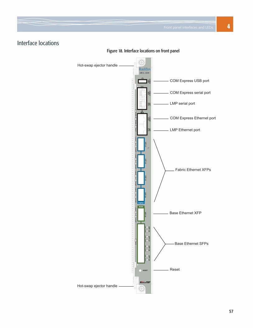
4Front panel interfaces and LEDs
57
Interface locationsFigure 18. Interface locations on front panel
AdvancedTCA R
ATCA - 2210
BASE
FABRIC
CO
M-E
US
BC
OM
-ES
ER
CO
M-E
ETH
XFP 1/1
XFP 1/2
XFP 1/3
LINK
POR
TLIN
KPO
RT
LINK
POR
TLIN
KPO
RT
SFP
1/9S
FP 1/8
SFP
1/7S
FP 1/6
RESET
XFP 1/5
XFP 1/4
LMP
ETH
LMP
SE
R
OO
SPW
RA
CT
PORT
H/S
LINK
LINK
LINK
LINK
LINK
PORT
PORT
PORT
PORT
LMP serial port
LMP Ethernet port
Fabric Ethernet XFPs
Base Ethernet SFPs
Base Ethernet XFP
Reset
COM Express Ethernet port
COM Express serial port
COM Express USB port
Hot-swap ejector handle
Hot-swap ejector handle
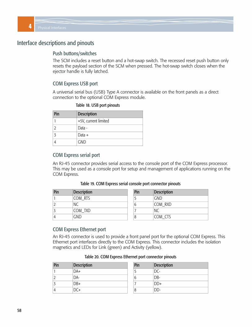
4 Physical Interfaces
58
Interface descriptions and pinouts
Push buttons/switchesThe SCM includes a reset button and a hot-swap switch. The recessed reset push button only resets the payload section of the SCM when pressed. The hot-swap switch closes when the ejector handle is fully latched.
COM Express USB port
A universal serial bus (USB) Type A connector is available on the front panels as a direct connection to the optional COM Express module.
COM Express serial port
An RJ-45 connector provides serial access to the console port of the COM Express processor. This may be used as a console port for setup and management of applications running on the COM Express.
COM Express Ethernet portAn RJ-45 connector is used to provide a front panel port for the optional COM Express. This Ethernet port interfaces directly to the COM Express. This connector includes the isolation magnetics and LEDs for Link (green) and Activity (yellow).
Table 18. USB port pinouts
Pin Description
1 +5V, current limited
2 Data -
3 Data +
4 GND
Table 19. COM Express serial console port connector pinouts
Pin Description Pin Description1 COM_RTS 5 GND2 NC 6 COM_RXD3 COM_TXD 7 NC4 GND 8 COM_CTS
Table 20. COM Express Ethernet port connector pinouts
Pin Description Pin Description1 DA+ 5 DC-2 DA- 6 DB-3 DB+ 7 DD+4 DC+ 8 DD-

4Front panel interfaces and LEDs
59
LMP serial console portAn RJ-45 connector provides serial access to the console port of the LMP (labeled LMP SER). This may be used as a console port for setup and management of applications running on the PowerQUICC III LMP.
Note: Use the LMP serial console port for temporary connections only. Use a shielded cable with the port.
LMP Ethernet maintenance portAn RJ-45 connector is used to provide a maintenance port for the SCM. This Ethernet port interfaces to the PowerQUICC III LMP. Two integrated LEDs on each connector indicate link status and activity (see page 63 for information on the LEDs).
*Unused pairs are terminated.
Note: Use the LMP Ethernet port for connections to indoor cables only. Use a shielded cable with the port for applications that need to fully comply with NEBS GR 1089 requirements.
XFP Base Ethernet and Fabric Ethernet portsThe XFP connectors are used to provide front panel access to the 10 Gb ports of the Base and the Fabric Ethernet switches. The front panel has four 10 Gb XFP sockets with 10 Gb XFI-to-XAUI interfaces to the Fabric Ethernet switch and one XFP socket with a 10 Gb XFI-to-XAUI interface to the Base Ethernet switch. Two LEDs next to each connector indicate link, activity, and port status. See page 63 for descriptions of the LEDs and their states.
Each connector is coupled to a switch port through a XAUI-to-XFI interface. The connector is inside a metal cage, which is connected to the SCM. You can install or remove XFP transceivers while the SCM is running, but they are not auto-detected. XFP module loading is optional.
Table 21. LMP serial console port connector pinouts
Pin Description Pin Description1 LMP_RTS 5 GND2 NC 6 LMP_RXD3 LMP_TXD 7 NC4 GND 8 LMP_CTS
Table 22. LMP maintenance port connector pinouts
Pin Description Pin Description1 TX+ 5 Unused (DC-)*2 TX- 6 RX-3 RX+ 7 Unused (DD+)*4 Unused (DC+)* 8 Unused (DD-)*

4 Physical Interfaces
60
An XFP port will not work if: no module is installedthe port is administratively disabled
See the ATCA-2210 Support page of RadiSys Web site at www.radisys.com for a list of XFP configurations and products that have been tested and confirmed by RadiSys to work with the SCM.
The XFP Base Ethernet & Fabric Ethernet connector pinouts are listed in the following table.
SFP Base Ethernet interface portsThe SFP Base Ethernet connectors are used to provide front panel access to the Base Ethernet switch. The front panel has four SFP sockets with 1 Gb SerDes interfaces to the Base Ethernet switch when optical SFPs are installed or 10/100 Mbit SerDes interfaces to the Base Ethernet switch when copper SFPs are installed. Two LEDs next to each connector indicate link, activity, and port status.
Each connector is directly coupled to a port of the Base Ethernet switch. You can install or remove SFP transceivers, which are auto-detected, while the SCM is running. SFP loading is optional.
An SFP port will not work if: no module is installedthe port is administratively disabled
See the ATCA-2210 Support page of RadiSys Web site at www.radisys.com for a list of SFP configurations and products that have been tested and confirmed by RadiSys to work with the SCM.
Table 23. XFP Base Ethernet & Fabric Ethernet connector pinouts
Pin Description Pin Description Pin Description1 GND 11 SDA 21 P_DOWN2 NC 12 MOD_ABS 22 +1.8V3 MOD_DESEL 13 MOD_NR 23 GND4 INTERRUPT 14 RX_LOS 24 REFCLK+5 TX_DIS 15 GND 25 REFCLK-6 +5.0V 16 GND 26 GND7 GND 17 RD- 27 GND8 +3.3V 18 RD+ 28 TD-9 +3.3V 19 GND 29 TD+10 SCL 20 +1.8V 30 GND

4Front panel interfaces and LEDs
61
The SFP Base Ethernet connector pinouts are listed in the following table.
Table 24. SFP Base Ethernet connector pinouts
Pin Description Pin Description1 GND 11 GND2 TXFAULT 12 RD-3 TXDIS 13 RD+4 MODDEF2 14 GND5 MODDEF1 15 +3,3V6 MODDEF0 16 +3.3V7 RATE SEL 17 GND8 LOS 18 TD+9 GND 19 TD-10 GND 20 GND11 GND 20 GND

4 Physical Interfaces
62
LED positionsFigure 19. LED positions on front panel
1/1 – Link status1/1 – Port status
1/2 – Link status1/2 – Port status
1/3 – Link status1/3 – Port status
1/4 – Link status1/4 – Port status
1/5 – Link status1/5 – Port status
1/6 – Link status1/6 – Port status
1/7 – Link status1/7 – Port status1/8 – Link status1/8 – Port status1/9 – Link status1/9 – Port status
Base 1 GE, SFP
Base 10 GE, XFP
Fabric 10 GE, XFP
LMP Fabric Ethernet (LMP ETH) link & port status
Out of service (OOS)
Power good (PWR)
Application specific (ACT)
COM Express Ethernet (COM-E) link & port status
Hot swap (H/S)

4Front panel interfaces and LEDs
63
LED descriptions and states
Table 25. Front panel LEDs
Description StatesOne bi-color Out of Service (OOS)“LED1” controlled by GPO signals on the IPMC.
Amber = OOS Off = normal operation
One green Power Good“LED2” controlled by GPO signals on the IPMC.
Green = power is good
One amber Module State“LED3” controlled by GPO signals on the IPMC.
Amber flashing = bootingAmber on = functioningOff = inactive
One blue Hot Swap ready“Blue LED” controlled by an IPMC output signal.
Blue = ready for hot swap
Two green COM Express and LMP Ethernet console port linksLED part of the RJ-45 connector - indicates PHY port activity.
Green = linkOff = no link
Two amber COM Express and LMP Ethernet console port activity
LED part of the RJ-45 connector - indicates PHY port activity. Amber blink = activityOff = no link or port disabled
Four green Fabric Ethernet XFP port status LEDs controlled by the LMP through the 10 G PHY LED signals.
Green = link is goodOff = no link or port disabled
Four green Fabric Ethernet XFP link/activity LEDs controlled by the LMP through the 10 G PHY LED signals.
Green = enabledGreen blink = activityOff = no link or port disabled
One green Base Ethernet XFP port status LEDs controlled by the LMP through the 10 G PHY LED signals.
Green = link is goodOff = no link or port disabled
One green Base Ethernet XFP link/activity LEDs controlled by the LMP through the 10 G PHY LED signals.
Green = enabledGreen blink = activityOff = no link or port disabled
One green Base Ethernet SFP link/activity LEDs part of the RJ-45 connector – indicates GE PHY port status, driven through the PHY LED signals.
Green = link is goodGreen blink = activityOff = no link or port disabled
Four green Base Ethernet SFP port statusLEDs part of the RJ-45 connector – indicates GE PHY port status, driven through the PHY LED signals.
Green = enabled Off = port disabled

4 Physical Interfaces
64
Backplane interfacesThe following SCM interfaces are available through the backplane:
Update channelsUpdate channels are the backplane connections that exist between a pair of SCMs operating on a redundant basis. Application software can use update channels for redundancy interlock.
If you configure a pair of SCMs to use the update channel for redundancy support, you must install the SCMs into hub slots linked by an update channel. The update channel for SCMs exists between physical slots 1 and 2 in a RadiSys 6-slot shelf and 7 and 8 in a RadiSys 14-slot shelf.
For more information on update channels and the slots that link redundant modules, see the appropriate Platform Hardware Reference manual (SYS-6000/6010 or SYS-6006) for the platform you are using.
Twelve 10/100/1000Base-T Base interface node portsOne inter-LMP link to a redundant SCM through the update channelOne Base Ethernet switch-to-switch link port through Base channel 2Dual 10/100Base-T Base interface port to one or two external Shelf Managers through Base channel 1Twelve 10 Gb XAUI Fabric interface node ports
Six synchronization channel clock input/outputs to the NTSMaster/slave link to NTS module clock through the update channelOne 10/100/1000Base-T link between COM Express modules through the Update channel when two redundant SCMs installed Two -48V power railsIPMB interface (two I2C ports) with programmable pull-upsEight hardware address lines, seven address/one parity
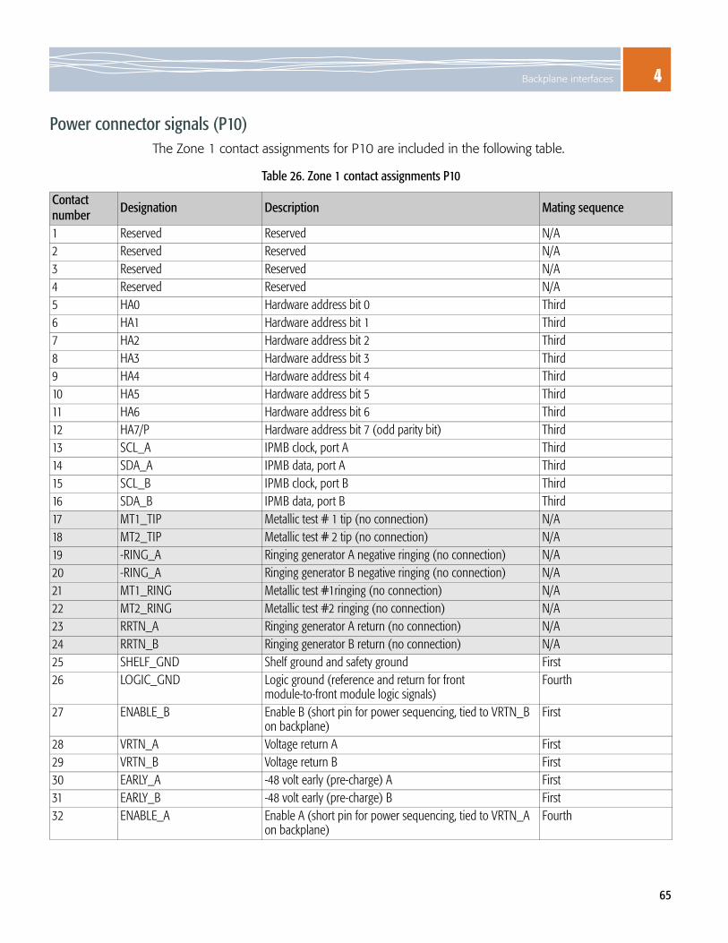
4Backplane interfaces
65
Power connector signals (P10)The Zone 1 contact assignments for P10 are included in the following table.
Table 26. Zone 1 contact assignments P10
Contact number Designation Description Mating sequence
1 Reserved Reserved N/A2 Reserved Reserved N/A3 Reserved Reserved N/A4 Reserved Reserved N/A5 HA0 Hardware address bit 0 Third6 HA1 Hardware address bit 1 Third7 HA2 Hardware address bit 2 Third8 HA3 Hardware address bit 3 Third9 HA4 Hardware address bit 4 Third10 HA5 Hardware address bit 5 Third11 HA6 Hardware address bit 6 Third12 HA7/P Hardware address bit 7 (odd parity bit) Third 13 SCL_A IPMB clock, port A Third14 SDA_A IPMB data, port A Third15 SCL_B IPMB clock, port B Third16 SDA_B IPMB data, port B Third17 MT1_TIP Metallic test # 1 tip (no connection) N/A18 MT2_TIP Metallic test # 2 tip (no connection) N/A19 -RING_A Ringing generator A negative ringing (no connection) N/A20 -RING_A Ringing generator B negative ringing (no connection) N/A21 MT1_RING Metallic test #1ringing (no connection) N/A22 MT2_RING Metallic test #2 ringing (no connection) N/A23 RRTN_A Ringing generator A return (no connection) N/A24 RRTN_B Ringing generator B return (no connection) N/A25 SHELF_GND Shelf ground and safety ground First26 LOGIC_GND Logic ground (reference and return for front
module-to-front module logic signals)Fourth
27 ENABLE_B Enable B (short pin for power sequencing, tied to VRTN_B on backplane)
First
28 VRTN_A Voltage return A First29 VRTN_B Voltage return B First30 EARLY_A -48 volt early (pre-charge) A First31 EARLY_B -48 volt early (pre-charge) B First32 ENABLE_A Enable A (short pin for power sequencing, tied to VRTN_A
on backplane)Fourth

4 Physical Interfaces
66
Backplane connector J20 signals
Backplane connector J21 signals
33 -48V_A -48 volt A, uses ENABLE_A to enable converters Second34 -48V_B -48 volt B, uses ENABLE_B to enable converters Third
Unused pin on SCM
Table 27. Backplane connector J20 signals
Row #Interface designation ab cd ef gh
1 Clks CLK1A+ CLK1A- CLK1B+ CLK1B- CLK2A+ CLK2A- CLK2B+ CLK2B-2 Update channel and
clocksTx4(UP)+ Tx4(UP)- Rx4(UP)+ Rx4(UP)- CLK3A+ CLK3A- CLK3B+ CLK3B-
3 Tx2(UP)+ Tx2(UP)- Rx2(UP)+ Rx2(UP)- Tx3(UP)+ Tx3(UP)- Rx3(UP)+ Rx3(UP)-4 Tx0(UP)+ Tx0(UP)- Rx0(UP)+ Rx0(UP)- Tx1(UP)+ Tx1(UP)- Rx1(UP)+ Rx1(UP)-5 Fabric channel 15 Tx2[15]+ Tx2[15]- Rx2[15]+ Rx2[15]- Tx3[15]+ Tx3[15]- Rx3[15]+ Rx3[15]-6 Tx0[15]+ Tx0[15]- Rx0[15]+ Rx0[15]- Tx1[15]+ Tx1[15]- Rx1[15]+ Rx1[15]-7 Fabric channel 14 Tx2[14]+ Tx2[14]- Rx2[14]+ Rx2[14]- Tx3[14]+ Tx3[14]- Rx3[14]+ Rx3[14]-8 Tx0[14]+ Tx0[14]- Rx0[14]+ Rx0[14]- Tx1[14]+ Tx1[14]- Rx1[14]+ Rx1[14]-9 Fabric channel 13 Tx2[13]+ Tx2[13]- Rx2[13]+ Rx2[13]- Tx3[13]+ Tx3[13]- Rx3[13]+ Rx3[13]-10 Tx0[13]+ Tx0[13]- Rx0[13]+ Rx0[13]- Tx1[13]+ Tx1[13]- Rx1[13]+ Rx1[13]-Note: Each differential pair has an individual L-shaped ground contact (not shown).
Table 28. Backplane connector J21 signals
Row # Interface designation ab cd ef gh
1 Fabric channel 12 Tx2[12]+ Tx2[12]- Rx2[12]+ Rx2[12]- Tx3[12]+ Tx3[12]- Rx3[12]+ Rx3[12]-2 Tx0[12]+ Tx0[12]- Rx0[12]+ Rx0[12]- Tx1[12]+ Tx1[12]- Rx1[12]+ Rx1[12]-3 Fabric channel 11 Tx2[11]+ Tx2[11]- Rx2[11]+ Rx2[11]- Tx3[11]+ Tx3[11]- Rx3[11]+ Rx3[11]-4 Tx0[11]+ Tx0[11]- Rx0[11]+ Rx0[11]- Tx1[11]+ Tx1[11]- Rx1[11]+ Rx1[11]-5 Fabric channel 10 Tx2[10]+ Tx2[10]- Rx2[10]+ Rx2[10]- Tx3[10]+ Tx3[10]- Rx3[10]+ Rx3[10]-6 Tx0[10]+ Tx0[10]- Rx0[10]+ Rx0[10]- Tx1[10]+ Tx1[10]- Rx1[10]+ Rx1[10]-7 Fabric channel 9 Tx2[9]+ Tx2[9]- Rx2[9]+ Rx2[9]- Tx3[9]+ Tx3[9]- Rx3[9]+ Rx3[9]-8 Tx0[9]+ Tx0[9]- Rx0[9]+ Rx0[9]- Tx1[9]+ Tx1[9]- Rx1[9]+ Rx1[9]-9 Fabric channel 8 Tx2[8]+ Tx2[8]- Rx2[8]+ Rx2[8]- Tx3[8]+ Tx3[8]- Rx3[8]+ Rx3[8]-10 Tx0[8]+ Tx0[8]- Rx0[8]+ Rx0[8]- Tx1[8]+ Tx1[8]- Rx1[8]+ Rx1[8]-Note: Each differential pair has an individual L-shaped ground contact (not shown).
Table 26. Zone 1 contact assignments P10 (continued)
Contact number Designation Description Mating sequence
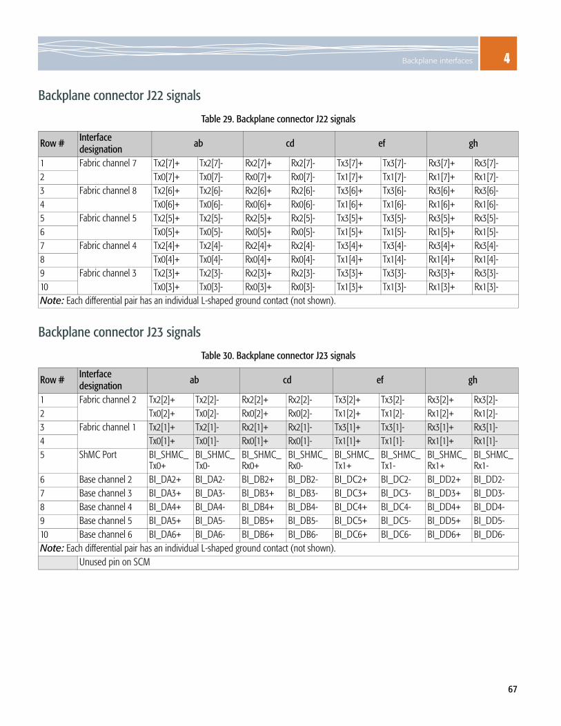
4Backplane interfaces
67
Backplane connector J22 signals
Backplane connector J23 signals
Table 29. Backplane connector J22 signals
Row #Interface designation ab cd ef gh
1 Fabric channel 7 Tx2[7]+ Tx2[7]- Rx2[7]+ Rx2[7]- Tx3[7]+ Tx3[7]- Rx3[7]+ Rx3[7]-2 Tx0[7]+ Tx0[7]- Rx0[7]+ Rx0[7]- Tx1[7]+ Tx1[7]- Rx1[7]+ Rx1[7]-3 Fabric channel 8 Tx2[6]+ Tx2[6]- Rx2[6]+ Rx2[6]- Tx3[6]+ Tx3[6]- Rx3[6]+ Rx3[6]-4 Tx0[6]+ Tx0[6]- Rx0[6]+ Rx0[6]- Tx1[6]+ Tx1[6]- Rx1[6]+ Rx1[6]-5 Fabric channel 5 Tx2[5]+ Tx2[5]- Rx2[5]+ Rx2[5]- Tx3[5]+ Tx3[5]- Rx3[5]+ Rx3[5]-6 Tx0[5]+ Tx0[5]- Rx0[5]+ Rx0[5]- Tx1[5]+ Tx1[5]- Rx1[5]+ Rx1[5]-7 Fabric channel 4 Tx2[4]+ Tx2[4]- Rx2[4]+ Rx2[4]- Tx3[4]+ Tx3[4]- Rx3[4]+ Rx3[4]-8 Tx0[4]+ Tx0[4]- Rx0[4]+ Rx0[4]- Tx1[4]+ Tx1[4]- Rx1[4]+ Rx1[4]-9 Fabric channel 3 Tx2[3]+ Tx2[3]- Rx2[3]+ Rx2[3]- Tx3[3]+ Tx3[3]- Rx3[3]+ Rx3[3]-10 Tx0[3]+ Tx0[3]- Rx0[3]+ Rx0[3]- Tx1[3]+ Tx1[3]- Rx1[3]+ Rx1[3]-Note: Each differential pair has an individual L-shaped ground contact (not shown).
Table 30. Backplane connector J23 signals
Row # Interface designation ab cd ef gh
1 Fabric channel 2 Tx2[2]+ Tx2[2]- Rx2[2]+ Rx2[2]- Tx3[2]+ Tx3[2]- Rx3[2]+ Rx3[2]-2 Tx0[2]+ Tx0[2]- Rx0[2]+ Rx0[2]- Tx1[2]+ Tx1[2]- Rx1[2]+ Rx1[2]-3 Fabric channel 1 Tx2[1]+ Tx2[1]- Rx2[1]+ Rx2[1]- Tx3[1]+ Tx3[1]- Rx3[1]+ Rx3[1]-4 Tx0[1]+ Tx0[1]- Rx0[1]+ Rx0[1]- Tx1[1]+ Tx1[1]- Rx1[1]+ Rx1[1]-5 ShMC Port BI_SHMC_
Tx0+BI_SHMC_Tx0-
BI_SHMC_Rx0+
BI_SHMC_Rx0-
BI_SHMC_Tx1+
BI_SHMC_Tx1-
BI_SHMC_Rx1+
BI_SHMC_Rx1-
6 Base channel 2 BI_DA2+ BI_DA2- BI_DB2+ BI_DB2- BI_DC2+ BI_DC2- BI_DD2+ BI_DD2-7 Base channel 3 BI_DA3+ BI_DA3- BI_DB3+ BI_DB3- BI_DC3+ BI_DC3- BI_DD3+ BI_DD3-8 Base channel 4 BI_DA4+ BI_DA4- BI_DB4+ BI_DB4- BI_DC4+ BI_DC4- BI_DD4+ BI_DD4-9 Base channel 5 BI_DA5+ BI_DA5- BI_DB5+ BI_DB5- BI_DC5+ BI_DC5- BI_DD5+ BI_DD5-10 Base channel 6 BI_DA6+ BI_DA6- BI_DB6+ BI_DB6- BI_DC6+ BI_DC6- BI_DD6+ BI_DD6-Note: Each differential pair has an individual L-shaped ground contact (not shown).
Unused pin on SCM

4 Physical Interfaces
68
Backplane connector J24 signals
Zone 3 connector J30 signals
Table 31. Backplane connector J24 signals
Row #Interface
designation ab cd ef gh
1 Base channel 7 BI_DA7+ BI_DA7- BI_DB7+ BI_DB7- BI_DC7+ BI_DC7- BI_DD7+ BI_DD7-2 Base channel 8 BI_DA8+ BI_DA8- BI_DB8+ BI_DB8- BI_DC8+ BI_DC8- BI_DD8+ BI_DD8-3 Base channel 9 BI_DA9+ BI_DA9- BI_DB9+ BI_DB9- BI_DC9+ BI_DC9- BI_DD9+ BI_DD9-4 Base channel 10 BI_DA10+ BI_DA10- BI_DB10+ BI_DB10- BI_DC10+ BI_DC10- BI_DD10+ BI_DD10-5 Base channel 11 BI_DA11+ BI_DA11- BI_DB11+ BI_DB11- BI_DC11+ BI_DC11- BI_DD11+ BI_DD11-6 Base channel 12 BI_DA12+ BI_DA12- BI_DB12+ BI_DB12- BI_DC12+ BI_DC12- BI_DD12+ BI_DD12-7 Base channel 13 BI_DA13+ BI_DA13- BI_DB13+ BI_DB13- BI_DC13+ BI_DC13- BI_DD13+ BI_DD13-8 Base channel 14 BI_DA14+ BI_DA14- BI_DB14+ BI_DB14- BI_DC14+ BI_DC14- BI_DD14+ BI_DD14-9 Base channel 15 BI_DA15+ BI_DA15- BI_DB15+ BI_DB15- BI_DC15+ BI_DC15- BI_DD15+ BI_DD15-10 Base channel 16 BI_DA16+ BI_DA16- BI_DB16+ BI_DB16- BI_DC16+ BI_DC16- BI_DD16+ BI_DD16-Note: Each differential pair has an individual L-shaped ground contact (not shown).
Table 32. Zone 3 connector J30 signals
Row # ab cd ef gh1 +12V_RTM +12V_RTM +12V_RTM +3.3V_IPMC_
LTDRTM_EJECT RTM_
PRESENT~RTM_HOTSWAP~
RTM_ENA~
2 +12V_RTM +12V_RTM +12V_RTM RTM_INTR~ IPMC_I2C_CLK IPMC_I2C_DAT PQ_I2C_CLK PQ_I2C_DAT3 SPI_RTM_
SEL~SLVA2 SLVA1 SLVA0 BLED_CLK BLED_DAT FLED_CLK FLED_DAT
4 RTM_RST~ SPI_CLK SPI_SDO SPI_SDI BASE_MDC BASE_MDIO FAB_XMDC FAB_XMDIO5 EXTCLK_
OUT-EXTCLK_OUT+
RTM_LMP_IRQ5
RTM_LMP_IRQ6
EXTCLK2_IN+ EXTCLK2_IN- EXTCLK1_IN+ EXTCLK1_IN-
6 NTS_8K_OUT+
NTS_8K_OUT-
NTS_19M_OUT+
NTS_19M_OUT-
EXTCLK4_IN+ EXTCLK4_IN- EXTCLK3_IN+ EXTCLK3_IN-
7 FAB:XERTMxTX0+
FAB:XERTMxTX0-
FAB:XERTMxTX1+
FAB:XERTMxTX1-
FAB:XERTMxTX2+
FAB:XERTMxTX2-
FAB:XERTMxTX3+
FAB:XERTMxTX3-
8 FAB:XERTMxRX0+
FAB:XERTMxRX0-
FAB:XERTMxRX1+
FAB:XERTMxRX1-
FAB:XERTMxRX2+
FAB:XERTMxRX2-
FAB:XERTMxRX3+
FAB:XERTMxRX3-
9 BASE:GERTM6TX+
BASE:GERTM6TX-
BASE:GERTM6RX+
BASE:GERTM6RX-
BASE:GERTM7TX+
BASE:GERTM7TX-
BASE:GERTM7RX+
BASE:GERTM7RX-
10 BASE:GERTM4TX+
BASE:GERTM4TX-
BASE:GERTM4RX+
BASE:GERTM4RX-
BASE:GERTM5TX+
BASE:GERTM5TX-
BASE:GERTM5RX+
BASE:GERTM5RX-
Note: Each differential pair has an individual L-shaped ground contact (not shown).

4Backplane interfaces
69
Zone 3 connector J31 signals
Table 33. Zone 3 connector J31 signals
Row # ab cd ef gh1 FAB:XE
RTM1TX0+FAB:XERTM1TX0-
FAB:XERTM1TX1+
FAB:XERTM1TX1-
FAB:XERTM1TX2+
FAB:XERTM1TX2-
FAB:XERTM1TX3+
FAB:XERTM1TX3-
2 FAB:XERTM1RX0+
FAB:XERTM1RX0-
FAB:XERTM1RX1+
FAB:XERTM1RX1-
FAB:XERTM1RX2+
FAB:XERTM1RX2-
FAB:XERTM1RX3+
FAB:XERTM1RX3-
3 FAB:XERTM3TX0+
FAB:XERTM3TX0-
FAB:XERTM3TX1+
FAB:XERTM3TX1-
FAB:XERTM3TX2+
FAB:XERTM3TX2-
FAB:XERTM3TX3+
FAB:XERTM3TX3-
4 FAB:XERTM3RX0+
FAB:XERTM3RX0-
FAB:XERTM3RX1+
FAB:XERTM3RX1-
FAB:XERTM3RX2+
FAB:XERTM3RX2-
FAB:XERTM3RX3+
FAB:XERTM3RX3-
5 COM_PCIE_TX1+
COM_PCIE_TX1-
COM_PCIE_RX1+
COM_PCIE_RX1-
NC NC BASE_XMDC BASE_XMDIO
6 NC NC NC NC NC NC NC NC7 FAB:XE
RTMzTX0+FAB:XERTMzTX0-
FAB:XERTMzTX1+
FAB:XERTMzTX1-
FAB:XERTMzTX2+
FAB:XERTMzTX2-
FAB:XERTMzTX3+
FAB:XERTMzTX3-
8 FAB:XERTMzRX0+
FAB:XERTMzRX0-
FAB:XERTMzRX1+
FAB:XERTMzRX1-
FAB:XERTMzRX2+
FAB:XERTMzRX2-
FAB:XERTMzRX3+
FAB:XERTMzRX3-
9 BASE:XERTM1TX0+
BASE:XERTM1TX0-
BASE:XERTM1TX1+
BASE:XERTM1TX1-
BASE:XERTM1TX2+
BASE:XERTM1TX2-
BASE:XERTM1TX3+
BASE:XERTM1TX3-
10 BASE:XERTM1RX0+
BASE:XERTM1RX0-
BASE:XERTM1RX1+
BASE:XERTM1RX1-
BASE:XERTM1RX2+
BASE:XERTM1RX2-
BASE:XERTM1RX3+
BASE:XERTM1RX3-
Note: Each differential pair has an individual L-shaped ground contact (not shown).NC = No connection
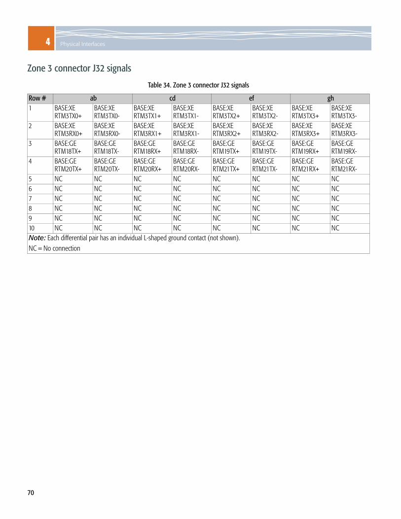
4 Physical Interfaces
70
Zone 3 connector J32 signals
Table 34. Zone 3 connector J32 signals
Row # ab cd ef gh1 BASE:XE
RTM3TX0+BASE:XERTM3TX0-
BASE:XERTM3TX1+
BASE:XERTM3TX1-
BASE:XERTM3TX2+
BASE:XERTM3TX2-
BASE:XERTM3TX3+
BASE:XERTM3TX3-
2 BASE:XERTM3RX0+
BASE:XERTM3RX0-
BASE:XERTM3RX1+
BASE:XERTM3RX1-
BASE:XERTM3RX2+
BASE:XERTM3RX2-
BASE:XERTM3RX3+
BASE:XERTM3RX3-
3 BASE:GERTM18TX+
BASE:GERTM18TX-
BASE:GERTM18RX+
BASE:GERTM18RX-
BASE:GERTM19TX+
BASE:GERTM19TX-
BASE:GERTM19RX+
BASE:GERTM19RX-
4 BASE:GERTM20TX+
BASE:GERTM20TX-
BASE:GERTM20RX+
BASE:GERTM20RX-
BASE:GERTM21TX+
BASE:GERTM21TX-
BASE:GERTM21RX+
BASE:GERTM21RX-
5 NC NC NC NC NC NC NC NC6 NC NC NC NC NC NC NC NC7 NC NC NC NC NC NC NC NC8 NC NC NC NC NC NC NC NC9 NC NC NC NC NC NC NC NC10 NC NC NC NC NC NC NC NCNote: Each differential pair has an individual L-shaped ground contact (not shown).NC = No connection

4Rear transition module
71
Rear transition module When an SCM is installed in a RadiSys shelf, an associated rear transition module (RTM) can be connected to provide external access to some of the SCM’s signals and electrical connections. The RTM is installed in the rear of the platform and connects to the SCM using the Zone 3 connectors.
A shelf peripheral module (SPM), such as the ATCA-5010, is used as the RTM when an SCM is installed in a 14-slot RadiSys shelf like the ATCA-6000. The SPM provides back-of-shelf access, including ATCA shelf management interfaces to various shelf peripherals and sensors.
SPMs are optional when SCMs are installed in RadiSys 6-slot shelves, such as the ATCA-6006, or in non-RadiSys shelves.
Electrical connections between the SCM and the associated RTM include:
Two to four 1 Gb SGMII/SerDes ports from the Base interface Two 10 Gb XAUI ports from Base interfaceOne to three 10 Gb XAUI ports from Fabric switch Four external reference clock inputsThree external system clock outputsI2C interface to IPMC for ID, temperature, temperature sensors, and control management
I2C interface to the LMP for IDSPI to the LMPPCI Express interface from COM Express siteSwitched 12 V from payload supplyCurrent limited 3.3 V from IPMC supplyRTM hot-swap switch closure signalHot-swap RTM LED output from the IPMC

4 Physical Interfaces
72
Figure 20 shows a block diagram example of an SPM designed for a 14-slot RadiSys shelf.
Figure 20. SPM block diagram
BITS/SSU clk
MagI/F RJ-45
SFP
SFP
Zone 3conn
Local powerconversion
ID
ClkInRefClk
Buf
ID & tempBuf
SFP
SFP
SPI
1Gb SD
SFP
SFP
SFP
1Gb SD
SPM (example)
SFP*
* Reserved for future implementation.
RJ-45
RJ-45
RJ-45
MagI/F
MagI/F
MagI/F
BITS/SSU clk
BITS/SSU clk
BITS/SSU clk

4Rear transition module
73
RTM hot-swap support buffersIn order to protect the RTM interface signals from disruption during insertion or removal of the RTM, buffers have been added to many of the RTM signals. These buffers are controlled through RTM_BUF_ENA~ on GPIO PC12 of the LMP. The buffer will be disabled whenever the RTM is not installed, or is being removed.
RTM interface signalsSpace has been allocated in the Zone 3 connectors for signals passing between the SCM and the RTM, including data path, configuration, and hot-swap signals. This represents a superset of the signals that may be used for various combinations of the SCM and the RTM.
Table 35. RTM interface signals
Signal nameDirection from SCM to RTM
Pins Description
+12V_RTM Out 6 Power source for RTM circuits, 3 Amp limit. This is current limited, and can be turned on and off by the IPMC.
+3.3V_IPMC_LTD Out 1 Power source for RTM hot-swap control circuits, 0.5 Amp limit. This is current limited, and can be turned on and off by the IPMC.
RTM_EJECT_IN~ In 1 Signal is grounded on RTM when ejector handle is closed (RTM fully seated). Pull-up to +3.3V_IPMI on SCM.
RTM_Present~ In 1 Indicates RTM is connected. This pin should be grounded on the RTM. Pulled up to +3.3V_IPMI on SCM.
RTM_HOTSWAP~ Out 1 Drive signal for RTM hot-swap indicator LED. 3.3V Signal goes low to turn on LED. Pull up to +3.3V_IPMC on RTM.
RTM_ENA~ Out 1 Low-true Enable signal for RTM on-board controller. Low enables, high disables (resets). Pull up to +3.3V_IPMC on RTM.
RTM_INTR~ In 1 Low-true interrupt signal from the RTM to the IPMC. Pulled up to +3.3V_IPMI on SCM.IPMC_I2C_CLK I/O 1 IPMC control bus clock. Pulled up to +3.3V_IPMI on SCM.IPMC_I2C_DAT I/O 1 IPMC control bus data. Pulled up to +3.3V_IPMI on SCM.PQ_12C_CLK I/O 1 PowerQUICC III control bus clock. Pulled up to Payload +3.3V on SCM.PQ_12C_DAT I/O 1 PowerQUICC III control bus data. Pulled up to Payload +3.3V on SCMSPI_RTM_SEL~ Out 1 SPI target select, low-true. RTM SPI bus slave devices will use this select along with
address bits to select a certain device. 3.3V signal from LMP goes low to select target device. Pull up to Payload +3.3V on RTM.
SPI_SLVA[0..2] Out 3 SPI bus target device address. The MSB indicates SMC3 (0) or RTM3 (1) as the target board. 3.3V signal from LMP.
BLED_CLK Out 1 Base switch LED control stream clock signal. 3.3 V signal from LMP controls RTM front panel LEDs.
BLED_DAT Out 1 Base switch LED control stream data signal. 3.3 V signal from LMP controls RTM front panel LEDs.
FLED_CLK Out 1 Fabric switch LED control stream clock signal. 3.3 V signal from LMP controls RTM front panel LEDs.

4 Physical Interfaces
74
FLED_DAT Out 1 Fabric switch LED control stream data signal. 3.3 V signal from LMP controls RTM front panel LEDs.
RTM_RST~ Out 1 Reset output to RTM peripherals (active low). Pull up to +3.3V_IPMC on RTM.SPI_CLK Out 1 SPI data transfer clock. 3.3 V signal from LMP.SPI_SDO Out 1 SPI data out (from LMP to target). 3.3V signal from LMP.SPI_SDI In 1 SPI data in (3.3 V signal from RTM target to LMP).BASE_MDC I/O 1 Base 1 Gb interface MDIO clock. 3.3 V signal from Base switch.BASE_MDIO Out 1 Base 1 Gb interface MDIO data. 3.3 V bidirectional signal from Base switch.BASE_XMDC I/O 1 Base 10 Gb interface MDIO clock. 2.5 V signal from Base switch.BASE_XMDIO Out 1 Base 10 Gb interface MDIO clock. 2.5 V bidirectional signal from Base switch.FABRIC_XMDC Out 1 Fabric 10 Gb interface MDIO clock. 2.5 V signal from Base switch.FABRIC_XMDIO I/O 1 Fabric 10 Gb interface MDIO data. 2.5 V bidirectional signal from Base switch.EXTCLK1_IN+/- In 2 Recovered clock 1 in, LVDS differentialEXTCLK2_IN+/- In 2 Recovered clock 2 in, LVDS differentialEXTCLK3_IN+/- In 2 Recovered clock 3 in, LVDS differentialEXTCLK4_IN+/- In 2 Recovered clock 4 in, LVDS differentialEXTCLK_OUT+/- Out 2 Clock out, LVDS differentialRTM_LMP_INTR5~ In 1 Interrupt (low-true) from the RTM to the LMP. Pulled up on SCM.RTM_LMP_INTR6~ In 1 Interrupt (low-true) from the RTM to the LMP. Pulled up on SCM.NTS_8K_OUT+/- Out 2 8KHz external clock out, LVDS differentialNTS_19M_OUT+/- Out 2 19.44MHz external clock out, LVDS differentialPCI_E_TX+/- Out 2 One PCI Express Tx lane, differentialPCI_E_RX+/- In 2 One PCI Express Rx lane, differentialBASE_GE_TX[0..1]+/- Out 16 Base interface 1 Gb Tx port, differential. Base interface SerDes signals. The number of
Base ports available depends on SCM component loading (stuffing).BASE_GE_RX[0..1]+/- In 16 Base interface 1 Gb Rx port, differential. Base interface SerDes signals. The number of
Base ports available depends on SCM component loading (stuffing).BASE_10G_TX[0..3]+/- Out 16 Base interface 10 Gb Tx port, differential. Base interface XAUI signals. The number of
Base ports available depends on SCM component loading (stuffing).BASE_10G_RX[0..3]+/- In 16 Base interface 10 Gb Rx port, differential. Base interface XAUI signals. The number of
Base ports available depends on SCM component loading (stuffing).FABRIC_10G_TX[0..3]+/- Out 32 Fabric interface 10 Gb Tx port, differential. Fabric interface XAUI signals. The number of
Fabric ports available depends on SCM component loading (stuffing).FABRIC_10G_RX[0..3]+/- In 32 Fabric interface 10 Gb Rx port, differential. Fabric interface XAUI signals. The number of
Fabric ports available depends on SCM component loading (stuffing).
Table 35. RTM interface signals (continued)
Signal nameDirection from SCM to RTM
Pins Description

4Internal interfaces
75
Internal interfaces
PowerQUICC III COP/JTAG headerThe common on-chip debug processor/Joint Test Action Group (COP/JTAG) port provides a full duplex serial interface for communications between the internal PowerQUICC III development support logic and an external development tool. The development port signals are available for use on a 16-pin surface mount COP/JTAG header located on the SCM.
The following tables provide the connector and pin functions for the header.
Table 36. PowerQUICC III COP/JTAG connector J3
Pin # Description Pin # Description1 JTAG_TDO 2 GND3 JTAG_TDI 4 JTAG_TRST~5 QREQ~ 6 PULL-UP7 JTAG_TCK 8 CKSTP_IN~9 JTAG_TMS 10 N/C11 COP_SRESET~ 12 GND13 COPHRESET~ 14 N/C15 CKSTP_OUT~ 16 GND
Table 37. PowerQUICC III COP/JTAG pin functions
Pin # Name Description1 TDO Development serial data out2 QACK Quiescent acknowledge (GND)3 TDI Development serial data in (Pull-up)4 TRST Test (soft) reset (Pull-down)5 QREQ~ Quiescent request (Pull-up)6 +3.3V +3.3V supply through 1K)7 TCK Development serial clock (Pull-up)8 CKSTP_IN~ Check Stop Input (Pull-up)9 TMS Test mode select input (Pull-up)10, 14 N.C. No connect11 SOFTREST~ Soft reset on PowerQUICC III (Pull-up)12 GND Digital GND13 HREST# Hard reset (Pull-up)14 Key Mechanical key (No connect)15 CKSTP_OUT~ Check stop output (Pull-up)
1
3
5
7
9
11
13
15
2
4
6
8
10
12
14
16

4 Physical Interfaces
76
ShMC headersThe following headers on the SCM are part of the shelf management controller (ShMC) circuit block.
H3 Serial debug and programming cable header
H1 JTAG debug cable header
J33 Auxiliary function and I/O FPGA programming cable header
H5 Watchdog and power jumper post header
Note: When the Shelf Manager function on the SCM is disabled, the IPMI controller is an IPMC rather than a ShMC.
PowerQUICC III port 80 interfaceThe PowerQUICC III Port 80 interface is used to connect to a RadiSys 84-6000-01 hex display assembly. The interface connects to the GPIO signals of the parallel bus of the PowerQUICC III.
Figure 21. Port 80 debug socket J4
Pin # Description Pin # Description1 +5V 2 PRT80D03 PRT80D1 4 PRT80D25 PRT80D3 6 PRT80D47 PRT80D5 8 PRT80D69 PRT80D7 10 MRESET# (reset)11 GND 12 LCS4# (write strobe)13 GND 14 N/C
13
75
119
13
42
1086
1412
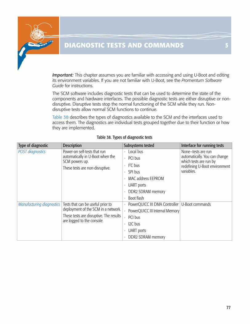
77
5DIAGNOSTIC TESTS AND COMMANDS
Important: This chapter assumes you are familiar with accessing and using U-Boot and editing its environment variables. If you are not familiar with U-Boot, see the Promentum Software Guide for instructions.
The SCM software includes diagnostic tests that can be used to determine the state of the components and hardware interfaces. The possible diagnostic tests are either disruptive or non-disruptive. Disruptive tests stop the normal functioning of the SCM while they run. Non-disruptive tests allow normal SCM functions to continue.
Table 38 describes the types of diagnostics available to the SCM and the interfaces used to access them. The diagnostics are individual tests grouped together due to their function or how they are implemented.
Table 38. Types of diagnostic tests
Type of diagnostic Description Subsystems tested Interface for running testsPOST diagnostics Power-on self-tests that run
automatically in U-Boot when the SCM powers up. These tests are non-disruptive.
Local bus PCI bus
I2C bus SPI bus MAC address EEPROMUART ports DDR2 SDRAM memoryBoot flash
None—tests are run automatically. You can change which tests are run by redefining U-Boot environment variables.
Manufacturing diagnostics Tests that can be useful prior to deployment of the SCM in a network. These tests are disruptive. The results are logged to the console.
PowerQUICC III DMA ControllerPowerQUICC III Internal MemoryPCI busI2C busUART portsDDR2 SDRAM memory
U-Boot commands

5 Diagnostic Tests and Commands
78
POST diagnosticsYou can add or disable POST diagnostics by editing the definitions of the U-Boot environment variables list in Table 39.
Table 39. U-Boot environment variables for controlling POST diagnostics
Environment variable Description and default valueBOARD_INIT_RAM_TEST This variable controls a memory test for U-Boot that runs by default and early in the boot-up process,
which is the only safe time to test U-Boot. Default value: LMPpostmtest 0x0 0x1000;LMPpostmtest 0x1fe00000 0x1fffffff
WARNING! Do not add the BOARD_INIT_RAM_TEST variable or its definition into the other postdiags variables. The memory ranges used by this variable (0x0 to 0x1000 and 0x1fe00000 to 0x1fffffff) are reserved for U-Boot. Testing these ranges at the wrong time can cause a conflict and prevent the SCM from booting.
postdiagscold This variable controls all the component tests except for the memory test, which run during a cold start (power up or reboot) of the SCM. Default value: LMPpostftest;LMPpostcpldtest;LMPposti2ctest; LMPpostntstest;LMPpostpcitest 0;LMPpostethtest;
postdiagswarm This variable controls all the component tests, except for the memory test, which run during a warm start (LMP reset) of the SCM. Default value: LMPpostftest;LMPpostcpldtest;LMPposti2ctest; LMPpostntstest;LMPpostpcitest 1;LMPpostethtest;
Note: The designation of 1 in the LMPpostpcitest value flags certain tests to run only the portions that do not disrupt the SCM and switch configurations.

5POST diagnostics
79
Adding testsBy default, only U-Boot memory is tested with the default settings. If you want to test the full range of SDRAM that is not used by U-Boot, add the manufacturing diagnostic LMPmtest and the RAM addresses to the postdiagscold and postdiagswarm variables by entering:
LMPmtest 0x1000 0x1fdffff0
LMPmtest is a comprehensive memory test that includes options. See DDR2 SDRAM test on page 84 for more information on this test and its options.
You can add any of the manufacturing diagnostics that start with LMP to the postdiagscold and postdiagswarm variables. Remember that each test affects the time it takes the SCM to boot.
Disabling testsTo keep the POST diagnostic tests from running in U-Boot:
1. Enter blank values for the variables, which deletes them from U-Boot: setenv BOARD_INIT_RAM_TEST setenv postdiagscold setenv postdiagswarm
2. Verify that the variables are deleted by entering:printenv
The variables should no longer appear in the list.
3. Make the changes permanent by entering:saveenv
4. Use the above procedures to make the same changes on the other boot flash. For instructions on accessing the other flash device, see the Promentum Software Guide.

5 Diagnostic Tests and Commands
80
Manufacturing diagnosticsManufacturing diagnostics are executed from U-Boot. The standard syntax for executing the tests follows this format:
ubootcommand required-parameter [optional-parameter] [iteration-count] [stop-on-error]
The parameters iteration-count and stop-on-error control the number of times a test is run and whether the test should stop immediately when an error occurs. The standard implementation of these parameters is described below.
iteration-count Sets the number of times to run the test, from 0 to 0xFF, with a default of 1. Use a value of 0 to run the test an infinite number of times. If running multiple iterations, you can stop the test by pressing Ctrl-c. Please note that a value is required for iteration-count if a value is specified for stop-on-error.
stop-on-error Specifies whether to stop the test immediately upon encountering an error. A value of 1 stops the test on an error; 0 (default) allows the test to continue. This optional parameter must be preceded by the iteration-count parameter.
If a particular test implements iteration-count or stop-on-error differently than is described above, the test description will note the difference.
To see a short description of the parameters for any U-Boot command, enter:help CommandName
Important: You cannot cancel tests invoked from U-Boot, but you can cancel subsequent iterations by pressing Ctrl-C.
Running tests as a groupWith manufacturing diagnostics, you have the option of running any of the tests with names that begin with “LMP” as a group. To do so, enter this U-Boot command:
diagnose
If you want to control which tests the diagnose command executes, modify the diagnose environment variable in U-Boot.

5Manufacturing diagnostics
81
Application LED GPIO testThis test checks the operation of the bi-colored Application LED, which is controlled by the LMP’s GPIO pins. This is a visual test you can use to run through the cycles of the LED: green, amber, and off. To confirm the successful completion of the test, monitor the LED while the test is running.
Syntax: LMPledtest color-type [iteration-count] [stop-on-error]
Options: color-type The LED color setting to test. Possible values are:0 = Tests both colors by alternately flashing each color1 = Tests green only2 = Tests amber only
stop-on-error The option has no effect, since this is a visual test.
EEPROM tests
MAC serial EEPROM testThis test checks the MAC address EEPROM by saving its contents and overwriting them with an incrementing pattern. After verifying the incrementing pattern can be read, the test restores the original contents of the EEPROM.
Syntax: LMPmactest [iteration-count] [stop-on-error]
Options: iteration-count For this test, 1 is the only valid value.
User serial EEPROM test This test checks the user EEPROM by saving its contents and overwriting them with an incrementing pattern. After verifying that the incrementing pattern can be read, the test restores the original contents of the EEPROM.
Syntax: LMPusertest [iteration-count] [stop-on-error]
Options: iteration-count For this test, 1 is the only valid value.

5 Diagnostic Tests and Commands
82
Ethernet switch internal operation testThis test checks the internal registers of the Base and the Fabric Ethernet switches. For POST diagnostics, all the registers are tested. For manufacturing diagnostics, certain PCI configuration registers and the CMIC_DEV_REV_ID register are checked, but the memory-mapped registers are not checked.
Syntax: LMPethswregtest switch [iteration-count] [stop-on-error]
Options: switch Specifies which switch to test. The possible values are:0 = Tests both the Fabric and Base switch registers1 = Tests the Fabric switch registers2 = Tests the Base switch registers
I2C bus testThis test scans the I2C bus for all possible I2C addresses and displays a list of the devices that respond. The iprobe command does not use any parameters.
A similar test can be run by the POST diagnostic, LMPposti2ctest. The test can be run from U-Boot safely at any time and confirms that only the expected devices respond.
Syntax: iprobe
LMP internal memory testThis test checks the memory caches and the SRAM on the LMP and within the LMP core complex.
Syntax: LMPintmemtest pattern-type [iteration-count] [stop-on-error]
Options: pattern-type 0 = Performs all memory tests1 = Writes simple patterns to memory2 = Tests addressability by walking 1s and 0s across the address bus3 = Tests data bus by walking 1s and 0s across the data bus

5Manufacturing diagnostics
83
Memory testsBoot flash and application flash testThis test validates data can be erased from and written to the flash. The test also validates whether data can be prevented from writing to the flash when the flash is write-protected. To preserve the contents of the flash, the test only processes one sector of the flash at a time.
The flash address ranges are:
Syntax: LMPftest start-addr stop-addr test-type [iteration-count] [stop-on-error]
Options: start-addr The starting address to test, which must be the first byte of a sector.
stop-addr The ending address to test, which must be the last byte of a sector.
test-type 0 = Performs all memory tests, but only tests the write-protect function if the address range includes the last sector of the boot flash device1 = Tests the write-protect function on the last sector of the boot flash identified by the address range2 = Erases sectors 3 = Erases sectors and rewrites with a pattern
Flash device Start address End address Sector size
Boot flash 0 (primary) 0xe0000000 0xe3ffffff 128 KB
Boot flash 1 (secondary) 0xe4000000 0xe7ffffff 128 KB
IPMC-selected boot image 0xfc000000 0xffffffff 128 KB

5 Diagnostic Tests and Commands
84
DDR2 SDRAM testThis test checks the DDR2 SDRAM. The way RAM is tested will vary, depending on which diagnostic is run.
When this test is run as a POST diagnostic using the U-Boot environment variable BOARD_INIT_RAM_TEST, a full RAM test is implemented. This is the only implementation of the test where the portion of SDRAM used by U-Boot is exercised.
For manufacturing diagnostics, the valid memory test addresses are 0x1000 to 0x1fdfffff. Any memory used to hold U-Boot code, data, and stack space cannot be specified.
Syntax: LMPmtest start-addr stop-addr test-type [iteration-count] [stop-on-error]
Options: start-addr The starting address to test, from 0x1000 to 0x1fdfffff.
stop-addr The ending address to test, from 0x1000 to 0x1fdfffff.
test-type 0 = Performs all memory tests1 = Writes simple patterns to memory2 = Tests addressability by walking 1s and 0s across the address bus3 = Tests data bus by walking 1s and 0s across the data bus4 = Generates ECC errors and verifies detection
Direct memory access (DMA) testThis test validates simple memory-to-memory transfers, PCI-bus DMA transfers to the register space of the Ethernet switch, and parallel transfers using all of the DMA channels.
Syntax: LMPdmatest dma-type [iteration-count] [stop-on-error]
Options: dma-type Specifies which DMAs to test. The possible values are: 0 = Tests all types of DMAs, one at a time1 = Tests memory-to-memory transfers2 = Tests memory-to-PCI memory-mapped register transfers 3 = Tests all active DMA channels in parallel

5Manufacturing diagnostics
85
NTS hitless switch testThis test checks device read and write operations through the SPI bus for the network timing subsystem. All registers are restored to their default values upon completion.
Syntax: ntsregtest [iteration-count] [stop-on-error]
Serial port access and information testThis test checks the serial port by issuing IPMC commands, which retrieve the device ID and also the sensors supported by the IPMC.
Syntax: LMPipmctest [iteration-count] [stop-on-error]

5 Diagnostic Tests and Commands
86

87
6MAINTENANCE AND TROUBLESHOOTING
Use this chapter as a general reference when performing maintenance and troubleshooting on the SCM.
MaintenanceIf an SCM needs to be installed, removed, or replaced, make sure to follow the ESD precautions described below (see Obey ESD precautions).
Many of the maintenance procedures can be performed using the SCM’s interface management software. The software can be accessed by an external computer using the serial and the Ethernet maintenance ports on the front panel.
Use the serial port to perform diagnostic and verification procedures.
Use the Ethernet maintenance port to connect to the network and to perform configuration procedures.
For additional information on accessing the interface management software and CLI commands, see the ATCA-2210 Switch and Control Module Installation Guide and the CLI Reference.
Obey ESD precautionsWARNING! Obey the electrostatic discharge (ESD) procedures described at www.radisys.com when you install or remove the product. Electrostatic discharge can cause permanent damage to static-sensitive components in this product. Important ESD procedures include:
Keep the product in its ESD shielding bag until a step tells you to remove it.Put on a grounded wrist strap before you move near or touch the product.Install the product only in a grounded work area.
Installing or replacing an SCM For information on installing or replacing an SCM, please see the ATCA-2210 Switch and Control Module Installation Guide.
Removing an SCM To remove an SCM from the shelf:
1. Disconnect all cables from the SCM front panel.
2. Loosen the SCM screws from the shelf.

6 Maintenance and Troubleshooting
88
3. Release the ejector latch in the position noted and then stop:
If the SCM is oriented vertically, release the lower ejector latch. If the SCM is oriented horizontally, release the right ejector latch.
WARNING! Never force open the ejector latch. Press the inner latch all the way in before you pull out the handle. If the latch does not open fully, close the latch and try again, making sure the inner latch is fully depressed.
4. The H/S blue light starts flashing. When the H/S blue light turns solid blue you are ready to remove the SCM.
Note: When only one SCM is present in the shelf and its shelf manager function is enabled, the H/S blue light will not turn solid blue.
5. Release the ejector latch in the position noted below. Use the same care in releasing the latch as you did for the other latch in Step 3.
If the SCM is oriented vertically, release the top ejector latch.If the SCM is oriented horizontally, release the left ejector latch.
6. Simultaneously pull both extractor latches to release the module from the slot.
7. Pull the SCM out of the slot.
8. Place the SCM on a flat, static-free surface.
Resetting an SCMIf you need to reset an SCM you can push the reset button on the front panel to invoke a payload reset.
You can also reset the SCM by issuing payload reset commands using the shelf management software. A payload reset acts as a “global reset.” The entire SCM including the LMP and the COM Express subsystem (if installed) is reset. All circuitry, with the exception of IPMI circuitry, is reset to a known initial state, clearing all remaining bits and initializing dynamic random access memory.
A reset signal specific to the COM Express also exists. The signal is directly controlled by the IPMC and follows the start-up of the SCM or can be issued using shelf management software.
For information on how software is affected when a reset or reboot occurs, see the Software Guide.
b) pull out
a) push inner latch in all the way
Example: Lower ejector latch for vertically oriented SCM

6Troubleshooting
89
TroubleshootingWhen you encounter a situation in which the SCM, or the platform it is installed in, does not perform as you expect, look for symptoms that might clarify the cause. Performing the following actions can aid you in diagnosing symptoms:
Check the state of the LEDs on all the modules in the platform, especially the power entry modules (PEMs) and rear transition modules (RTMs).
Check the shelf-management events logged in the system event log (SEL), which is accessible through the system manager. The Shelf Management Software Reference provides details on how to use the SEL.
Information about the Base Ethernet configuration, which can be generated using the show commands in the base-interface management CLI.
Information about the Fabric Ethernet configuration, which can be generated using show commands in the fabric-interface management CLI.
Verify the IP address and the subnet mask assignment. See the Software Guide for details on verifying these assignments.
Verify the Fabric Ethernet interface is communicating properly. See the Software Guide for information on diagnosing communication and connection issues.
Check temperatures on the SCM. The hpiapp application can be used to query the Alarm Table, which provides a way to query the actual temperature readings of devices. See the Shelf Management Software Reference for information on how to use the hpiapp application and how to perform these queries.
Verify SCMs are of the same type and are using the same software version, when installing two on the same platform for redundancy purposes. For example, you cannot use an ATCA-2210 SCM with an ATCA-2100 SCM.
Use Table 40 on page 90 for diagnosing your situation. Look for symptoms that apply, then follow the recommended action (or actions) for that symptom. When an action reveals the cause of the problem, resolve the problem as indicated.

6 Maintenance and Troubleshooting
90
Table 40. Troubleshooting actions based on symptoms
Symptom RecommendationThe power LED on the SCM or another module is not lit.
Verify that the module is fully inserted. Inspect the module connector pins for damage. If connector pins show no sign of damage, you can try the following:
carefully insert the module into a different slotcarefully insert a different module in the original slot
WARNING! Do not force the modules into the slots:To avoid damage to connectors, make sure the rear slot is either empty or contains a module that is compatible with the module being inserted. If the module does not slide easily, make sure you are inserting it into the correct slot and that it is aligned properly.
Check to see if the module’s Shelf Manager is disabled and whether the module is waiting for an external Shelf Manager to enable it.
Communication cannot be established between Ethernet nodes within the platform.
Connect to the SCM through the serial (LMP SER) or the Ethernet maintenance (LMP ETH) ports. Use management CLI commands on the Base Ethernet to diagnose the cause. In particular, verify that an IP address has been assigned to the node, an appropriate subnet mask is assigned to the node, the node is within a reachable VLAN, and routing instructions do not prevent the communication. If switch control CLI commands fail to work with one of the nodes, check the system event log to verify that the node's Ethernet backplane interface was activated. See the CLI Reference for descriptions of the commands and command syntax.
The SCM is in debug mode according to the login banner.
Restore valid Shelf FRU Information using the frurw utility as described in the Shelf Management Software Reference.
A module does not work correctly. Check the system event log for significant events related to the module. In particular, verify that the module worked correctly when it was installed, and look for any events since then that would account for why the module stopped working correctly. If the log information does not reveal useful symptoms, power down the module, slide it out, perhaps move it to a different slot, slide it back in, and power it back up. If appropriate, install a different module of the same kind to help determine whether the module might be defective.
The SCM’s embedded software is corrupted or it fails to boot properly with newly upgraded software.
See the Software Guide for instructions on loading software through either U-Boot or from the secondary flash.
Intermittently, the SCM and other installed modules experience random data errors.
Verify that the platform’s frame-ground connection is properly connected to a high-quality earth-ground connection. Check for electrical noise at the backplane power connections and at the power entry module power inputs. Consider the possibility of a malfunctioning module causing electrical noise on backplane connections.
The SCM or another module overheats
Verify no cover plates are installed. Empty slots must have air management panels rather than cover plates installed to properly maintain airflow and emissions. Use shelf management software to check temperatures at the air intake, on the module, and at the platform’s air exhaust. Use the information to determine whether the overheating may be caused by warm facility air, a module failure, or a failed fan module. Try moving the module to a different slot to see if that resolves the overheating. Verify there is at least two inches of clearance between the side of the shelf and the side of the rack cabinet. Check the air filter for obstructions and dirt.

91
ASPECIFICATIONS
EnvironmentalRadiSys does not provide environmental certification testing, because any meaningful emissions agency certification must include the entire system. Thus, the SCM is designed and tested to pass the environmental specifications noted below, but is not certified. Please note the operating environment must provide sufficient airflow across the SCM to keep it within its temperature specification.
Table 41. Environmental specifications
Characteristic State ValueTemperature (ambient)
Operating +5° C to +45° C30° C/hr rate of change
Short term operating 1 –5° C to +55° C30° C/hr rate of change
Storage –40° C to +70 ° C
Rate of change:23° C to -40° C at 30° C/hr-40° C to 23° C at 13° C/min+23o C to +70o C at 30° C/hr+70° C to +23° C at 10° C/min
Relative humidity Operating 5% to 85% RH non-condensingShort term operating1 5% to 90% RH non-condensing at +30° CStorage 5% to 90% RH non-condensing at +40o CShort term storage1 5% to 95% RH non-condensing at +40o C
Altitude Operating2 Up to 1800 meters (5,905 feet), +55° C> 1800 meters up to 4000 meters (13,123 feet), derated linearly to +45° C
Shock (drop) UnpackedFree fall, corners and edges
0 to < 10 kg = 100 mm drop 10 to < 25 kg = 75 mm drop
Packaged (Unpalletized)Free fall, corners and edges
0 to < 10 kg = 750 mm drop10 to < 25 kg = 600 mm drop
Palletized 300 mm free fall dropVibration Operating 0.1g, 5 to 100 Hz and back, 0.1 octave/min sine sweep 2
Transportation (packaged) 0.5g, 5 to 50 Hz and back, 0.1 octave/min sine sweep 2
3.0g, 50 to 500 Hz and back, 0.25 octave/min sine sweep 2
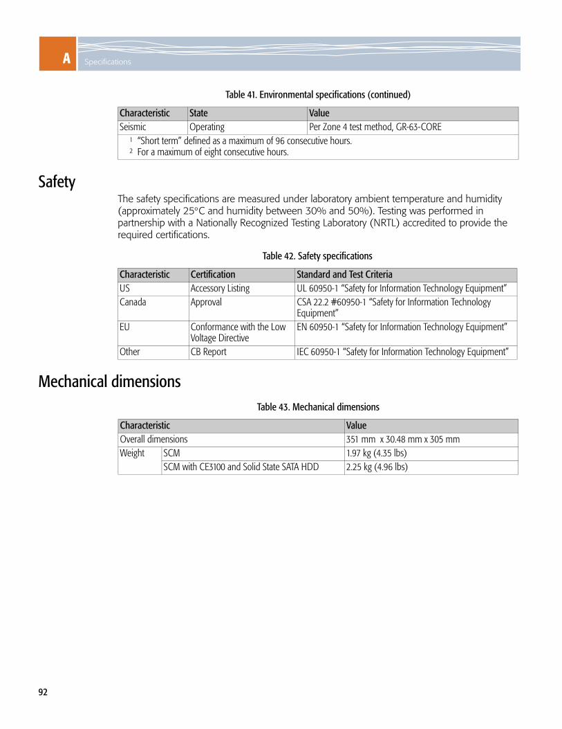
A Specifications
92
SafetyThe safety specifications are measured under laboratory ambient temperature and humidity (approximately 25°C and humidity between 30% and 50%). Testing was performed in partnership with a Nationally Recognized Testing Laboratory (NRTL) accredited to provide the required certifications.
Mechanical dimensions
Seismic Operating Per Zone 4 test method, GR-63-CORE1 “Short term” defined as a maximum of 96 consecutive hours.2 For a maximum of eight consecutive hours.
Table 41. Environmental specifications (continued)
Characteristic State Value
Table 42. Safety specifications
Characteristic Certification Standard and Test CriteriaUS Accessory Listing UL 60950-1 “Safety for Information Technology Equipment”Canada Approval CSA 22.2 #60950-1 “Safety for Information Technology
Equipment”EU Conformance with the Low
Voltage DirectiveEN 60950-1 “Safety for Information Technology Equipment”
Other CB Report IEC 60950-1 “Safety for Information Technology Equipment”
Table 43. Mechanical dimensions
Characteristic ValueOverall dimensions 351 mm x 30.48 mm x 305 mm Weight SCM 1.97 kg (4.35 lbs)
SCM with CE3100 and Solid State SATA HDD 2.25 kg (4.96 lbs)

AElectromagnetic compatibility (EMC)
93
Electromagnetic compatibility (EMC)The SCM has been tested and found to comply with the requirements detailed in the following standards when installed in a representative shelf:
ICES-003 Class AFCC Part 15 Class AEN 55022:1998 Class AEN 300 386 V1.3.3EN 55024:1998 + A1 + A2
WARNING! This is a Class A product. In a domestic environment this product may cause radio interference in which case the user may be required to take adequate measures.
This equipment has been tested and found to comply with the limits for a Class A digital device, pursuant to Part 15 of the FCC Rules. These limits are designed to provide reasonable protection against harmful interference when the equipment is operated in a commercial environment. This equipment generates, uses, and can radiate radio frequency energy, and if not installed and used in accordance with the instruction manual, may cause harmful interference to radio communications. Operation of this equipment in a residential area is likely to cause harmful interference in which case the user will be required to correct the interference at his own expense.
Modifications made to the product, unless expressly approved by RadiSys Corporation, could void the user’s authority to operate the equipment.
The interface ports are designed for use as intra-building interfaces only (Type 2 or Type 4 ports as described in GR-1089-CORE, Issue 4) and require isolation from the exposed Outside Plant (OSP) cabling. The addition of Primary Protectors is not sufficient protection in order to connect these interfaces metallically to OSP wiring.
Power Table 44. SCM power emissions
Characteristic State Standard and CriteriaNominal operating voltages -48V/-60V ETS 300 132-2 Static voltage levels
Table 45. SCM power consumption summary
Supply WattsSCM 120RTM 12COM Express with HDD 27.5

A Specifications
94
Reliability The reported failure rates for the SCM do not represent catastrophic failure. Catastrophic failure rates will vary based on application environment and features critical to the intended function.Failure rate (Fit): 8849.558 failures in 109 @ 55 C°Mean time between failures (MTBF): 113,000 hours @ 35 C°

95
BIPMI COMMANDS AND MANAGED SENSORS
IPMI commandsThe following IPMI commands are supported by the SCM.
Table 46. Supported IPMI commands
Message commands NetFn CommandGet device ID App (06h) 01hCold reset App (06h) 02hWarm reset App (06h) 03hBroadcast “get device ID” App (06h) 01hReset watchdog timer App (06h) 22hSet watchdog timer App (06h) 24hGet watchdog timer App (06h) 25hGet channel info App (06h) 42hSet event receiver S/E (04h) 00hGet event receiver S/E (04h) 01hPlatform event (a.k.a. “event message”) S/E (04h) 02hGet device SDR info S/E (04h) 20hGet device SDR S/E (04h) 21hReserved device SDR repository S/E (04h) 22hSet sensor hysteresis S/E (04h) 24hGet sensor hysteresis S/E (04h) 25hSet sensor threshold S/E (04h) 26hGet sensor threshold S/E (04h) 27hSet sensor event enable S/E (04h) 28hGet sensor event enable S/E (04h) 29hGet sensor reading S/E (04h) 2DhGet FRU inventory area info Storage (0Ah) 10hRead FRU data Storage (0Ah) 11hWrite FRU data Storage (0Ah)‘ 12hGet SDR Storage (0Ah) 20hReserve SDR repository Storage (0Ah) 22hGet SDR Storage (0Ah) 23hPartial add SDR Storage (0Ah) 25hGet SEL info Storage (0Ah) 40hGet SEL entry Storage (0Ah) 43h

B IPMI commands and Managed Sensors
96
Add SEL entry Storage (0Ah) 44hClear SEL Storage (0Ah) 47hGet SEL time Storage (0Ah) 48hSet SEL time Storage (0Ah) 49hGet PICMG properties PICMG (2Ch) 00hGet address info PICMG (2Ch) 01hFRU control PICMG (2Ch) 04hGet FRU LED properties PICMG (2Ch) 05hGet LED color capabilities PICMG (2Ch) 06hSet FRU LED state PICMG (2Ch) 07hGet FRU LED state PICMG (2Ch) 08hSet IPMB state PICMG (2Ch) 09hSet FRU activation policy PICMG (2Ch) 0AhGet FRU activation policy PICMG (2Ch) 0BhSet FRU activation PICMG (2Ch) OChGet device locator record ID PICMG (2Ch) ODhSet port state PICMG (2Ch) 0EhGet port state PICMG (2Ch) 0FhCompute power properties PICMG (2Ch) 10hSet power level PICMG (2Ch) 11hGet power level PICMG (2Ch) 12hGet shelf address info (ShMC) PICMG (2Ch) 02hSet shelf address info (ShMC) PICMG (2Ch) 03h
Table 46. Supported IPMI commands (continued)
Message commands NetFn Command

BSensors on the SCM
97
Sensors on the SCMThe SCM manages sensors with sensor data record (SDR) support. The SCM implements a Type 12h (0x12) management controller device locator record for identifying the management controller and a Type 1h (0x01) full sensor record for describing the sensor.
Rather than being an actual physical component, the sensors are an accumulation of the information gathered by the measuring devices and the IPMC on the SCM. The IPMC monitors conditions and detects digital state changes or analog values crossing thresholds. When transitions occur, the IPMC sends the information on to the Shelf Manager as events. The Shelf Manager may in turn send these events on to a System Manager.
Types of sensors
The SCM implements the following types of sensors.
Discrete — A discrete sensor can have up to 16 bit-mapped states, with one state as true.
Digital — A digital sensor has two possible states, only one of which can be active at any given time. For example, a digital sensor monitoring the power may have a state detecting whether the power is good or the power is not good.
Threshold — A threshold sensor has a range of 256 values, which represent measurements on the SCM and its FRUs. Temperature, voltage, current, and fan speed sensors are examples of threshold sensors.
The possible thresholds are the shown below.
OEM — An OEM sensor has its states defined by the manufacturer. The reading types of these sensors are sometimes defined as “sensor-specific.”
Table 47. Threshold types
Threshold type DescriptionUNR Upper non-recoverable thresholds generate a critical alarm on the high side.
UC Upper critical thresholds generate a major alarm on the high side.UNC Upper non-critical thresholds generate a minor alarm on the high side.LNC Lower non-critical thresholds generate a minor alarm on the low side.
LC Lower critical thresholds generate a major alarm on the low side.LNR Lower non-recoverable thresholds typically generate a critical alarm on the low side.
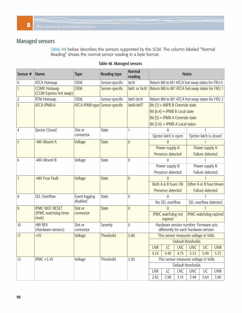
B IPMI commands and Managed Sensors
98
Managed sensorsTable 48 below describes the sensors supported by the SCM. The column labeled “Normal Reading” shows the normal sensor reading in a byte format.
Table 48. Managed sensors
Sensor # Name Type Reading type Normal reading
Notes
0 ATCA Hotswap OEM Sensor-specific 0x10 Return M0 to M7 ATCA hot-swap states for FRU 0 1 COME Hotswap
(COM Express hot swap)OEM Sensor-specific 0x01 or 0x10 Return M0 to M7 ATCA hot-swap states for FRU 1
2 RTM Hotswap OEM Sensor-specific 0x01-0x10 Return M0 to M7 ATCA hot-swap states for FRU 23 ATCA IPMB-0 ATCA IPMB type Sensor-specific 0x00-0xFF Bit [7] = IMPB B Override state
Bit [6:4] = IPMB B Local stateBit [3] = IPMB A Override stateBit [2:0} = IPMB A Local status
4 Ejector Closed Slot or connector
State 1 0 1Ejector latch is open Ejector latch is closed
5 -48V Absent A Voltage State 0 0 1Power supply A
Presence detectedPower supply AFailure detected
6 -48V Absent B Voltage State 0 0 1Power supply B
Presence detectedPower supply BFailure detected
7 -48V Fuse Fault Voltage State 0 0 1Both A & B fuses OKPresence detected
Either A or B fuse blownFailure detected
8 SEL Overflow Event logging disabled
State 0 0 1No SEL overflow SEL overflow detected
9 IPMC WDT RESET(IPMC watchdog timer reset)
Slot or connector
State 0 0 1IPMC watchdog not
expiredIPMC watchdog expired
10 HW REV(Hardware version)
Slot or connector
Severity 0 Hardware version number. Firmware acts differently for each hardware version.
11 +5V Voltage Threshold 5.00 This sensor measures voltage in Volts.Default thresholds
LNR LC LNC UNC UC UNR4.24 4.49 4.75 5.23 5.49 5.75
12 IPMC +3.3V Voltage Threshold 3.30 This sensor measures voltage in VoltsDefault thresholds
LNR LC LNC UNC UC UNR2.82 2.98 3.14 3.48 3.64 3.80

BSensors on the SCM
99
13 +3.3V Voltage Threshold 3.30 This sensor measures voltage in VoltsDefault thresholds
LNR LC LNC UNC UC UNR2.82 2.98 3.14 3.48 3.64 3.80
14 +2.5V Voltage Threshold 2.50 This sensor measures voltage in VoltsDefault thresholds
LNR LC LNC UNC UC UNR2.13 2.25 2.38 2.62 2.75 2.88
15 +1.25V Voltage Threshold 1.25 This sensor measures voltage in VoltsDefault thresholds
LNR LC LNC UNC UC UNR1.06 1.12 1.18 1.30 1.37 1.43
16 +1.8V Voltage Threshold 1.80 This sensor measures voltage in VoltsDefault thresholds
LNR LC LNC UNC UC UNR1.53 1.62 1.70 1.88 1.98 2.03
17 +12V Voltage Threshold 12.0 This sensor measures voltage in VoltsDefault thresholds
LNR LC LNC UNC UC UNR10.21 10.79 11.38 12.55 13.13 13.76
18 +1.2V Voltage Threshold 1.20 This sensor measures voltage in VoltsDefault thresholds
LNR LC LNC UNC UC UNR1.02 1.07 1.14 1.26 1.31 1.38
19 Inlet Temp Temp Threshold 25 This sensor measures temperature in °CDefault thresholds
LNR LC LNC UNC UC UNR-10.0 -5.0 0.0 63 68 82
20 XFP Temp Temp Threshold 25 This sensor measures temperature in °CDefault thresholds
LNR LC LNC UNC UC UNR-10.0 -5.0 0.0 72 77 87
21 Fabric Temp Temp Threshold 25 This sensor measure temperature in °CDefault thresholds
LNR LC LNC UNC UC UNR-10 -5 0 55 70 85
Table 48. Managed sensors (continued)
Sensor # Name Type Reading typeNormal reading Notes

B IPMI commands and Managed Sensors
100
22 PIM Alarm(Power input module alarm)
Power supply Digital 0 or 1 0 1PIM alarm not asserted PIM alarm asserted
23 PB Reset(Push button reset)
Slot or connector
Digital 0 or 1 0 1Asserted Not asserted
24 IPMB 0 PU Ch A Slot or connector
Discrete N/A 0 1 2No Pull-Up Half Pull-up Full Pull-up
25 IPMB 0 PU Ch B Slot or connector
Discrete N/A 0 1 2No Pull-Up Half Pull-up Full Pull-up
26 ComE Present(COM Express present)
Module or board
Digital 0 or 1 0 1COM Express present COM Express not
present27 IPMC Watchdog Slot or
connectorDiscrete N/A Generates an event when the IPMC is reset
29 RTM Present Slot or connector
Digital 0 or 1 0 1RTM is present RTM is not present
FRU 1 COM Express sensors — only present if COM Express is present 160 ComE Pwr Fail Slot or
connector Digital 0 0 1
RTM power ok RTM power fail161 ComE Type Slot or
connectorDiscrete N/A 2-9
Module type162 ComE Eject Slot or
connectorDigital N/A 0 1
COM Express not present
COM Express present
FRU 2 RTM sensors — only present if RTM is present 163 RTM Temp Temp Threshold 25 This sensor measures temperature in °C
Default thresholdsLNR LC LNC UNC UC UNR-10 -5 0 65 70 80
164 RTM 12C Ready Slot or connector
Digital 1 0 1RTM I2C is not ready RTM I2C is ready
165 RTM Pwr Fail Slot or connector
Digital 0 0 1RTM power ok RTM power fail
166 RTM Eject Slot or connector
Digital 1 0 1RTM latch is open RTM latch is closed
Table 48. Managed sensors (continued)
Sensor # Name Type Reading typeNormal reading Notes

BBoard health and event generation
101
Board health and event generationThe managed sensors have settings that determine the health and the event generation for the SCM. The setting descriptions are as follows:
Health check: Sensor must be in a nominal state for the SCM to transfer from a state where no services are enabled on the module to a state where the module is going from M3 to M4 (hot swap).
Alarm level: The type of alarm associated with the event. Threshold sensor events generally map directly to alarms and have an alarm level. The event to alarm mapping is done in the Shelf Manager, which maintains the Domain Alarm Table (DAT) and drives the Telco alarm outputs.
The IPMC generates non-threshold events, but the Shelf Manager does not generate alarms (or alarm levels) for them. The IPMC can send these events on to a system manager, which may be configured to generate alarms for non-threshold events. See the Shelf Management Software Reference for more information on the Shelf Manager and the events it monitors.
Local scanning disabled: Measurement or device status is not updated or visible to the IPMC.
Local event generation disabled: Events are not logged in the IPMC system event log.
Remote scanning disabled: The status of a sensor is not updated or visible to other modules on the shelf. For example, a Shelf Manager would not be able to check the status of this sensor.
Remote event generation disabled: Sensors events will not be generated by the SCM and sent on to the other modules installed on the shelf.
Table 49 on page 102 shows the health and the event generation settings for each managed sensor.

B IPMI commands and Managed Sensors
102
Table 49. Board health and event generation
Sensor #
Name Health check
Alarm level (if applicable)
Local scanning disabled
Local event generation disabled
Remote scanning disabled
Remote event generation disabled
0 ATCA Hotswap N/A No No No No1 COME Hotswap
(COM Express hot swap)N/A No No No No
2 RTM Hotswap N/A No No No No3 ATCA IPMB-0 N/A No No No No4 Ejector Closed N/A No No No No5 -48V Absent A N/A No No No No6 -48 V Absent B N/A No No No No7 -48 V Fuse Fault N/A No No No No8 SEL Overflow N/A No No No No9 IPMC WDT RESET
(IPMC watchdog timer reset)
N/A No No No No
10 HW REV(Hardware version)
Minor, Major, Critical voltage high
No No No No
Minor, Major, Critical voltage low
11 +5V Minor, Major, Critical voltage high
No Varies* No Varies*
Minor, Major, Critical voltage low
12 IPMC +3.3V Minor, Major, Critical voltage high
No No No No
Minor Major, Critical voltage low
13 +3.3V Minor, Major, Critical voltage high
No Varies* No Varies*
Minor, Major, Critical voltage low
14 +2.5V Minor, Major, Critical voltage high
No Varies* No Varies*
Minor, Major, Critical voltage low
15 +1.25V Minor, Major, Critical voltage high
No Varies* No Varies*
Minor, Major, Critical voltage low

BBoard health and event generation
103
16 +1.8V Minor, Major, Critical voltage high
No Varies* No Varies*
Minor, Major, Critical voltage low
17 +12V Minor, Major, Critical voltage high
No Varies* No Varies*
Minor, Major, Critical voltage low
18 +1.2V Minor, Major, Critical voltage high
No Varies* No Varies*
Minor, Major, Critical voltage low
19 Inlet Temp Minor, Major, Critical temperature high
No No No No
Minor, Major, Critical temperature low
20 XFP Temp Minor, Major, Critical temperature high
No No No No
Minor, Major, Critical temperature low
21 Fabric Temp Minor, Major, Critical temperature high
No No No No
Minor, Major, Critical temperature low
22 PIM Alarm N/A No Varies* No Varies*23 PB Reset
(Push button reset)N/A No Varies* No Varies*
24 IPMB 0 PU Ch A N/A No Varies* No Varies25 IPMB 0 PU Ch B N/A No No No No26 ComE Present
(COM Express present)N/A No No No No
27 IPMC Watchdog N/A No No No No29 RTM Present N/A No No No Varies**
FRU 1 COM Express sensors — only present if COM Express is present160 ComE Pwr Fail N/A No Varies** No Varies**161 ComE Type N/A No Varies** No Varies**162 ComE Eject N/A No Varies** No Varies**
Table 49. Board health and event generation (continued)
Sensor # Name Health
checkAlarm level (if applicable)
Local scanning disabled
Local event generation disabled
Remote scanning disabled
Remote event generation disabled

B IPMI commands and Managed Sensors
104
FRU 2 RTM sensors — only present if RTM is present 163 RTM Temp Minor, Major, Critical
temperature highNo Varies*** No Varies***
Minor, Major, Critical temperature low
164 RTM I2C Ready N/A No Varies*** No Varies***165 RTM Power Fail N/A No Varies*** No Varies***166 RTM Eject N/A No Varies*** No Varies**** Event generation is enabled when the payload power is turned on.** Event generation is enabled is a COM Express is detected. *** Event generation is enabled if an RTM is detected.
Table 49. Board health and event generation (continued)
Sensor # Name Health
checkAlarm level (if applicable)
Local scanning disabled
Local event generation disabled
Remote scanning disabled
Remote event generation disabled

BAlarms troubleshooting
105
Alarms troubleshooting Use Table 50 for troubleshooting any alarms, faults, and errors that may be triggered on the SCM.
Table 50. Alarms troubleshooting
Sensor # Name Alarm level
(if applicable) Possible fault or error Action to take
0 ATCA Hotswap N/A M7 state Remove the SCM and reinsert to see if problem persists. If problem still persists, then remove or hot swap the SCM and contact customer support.
1 COME Hotswap(COM Express hot swap)
N/A M7 state Remove the SCM and reinsert to see if problem persists. If problem still persists, then remove or hot swap the SCM and contact customer support.
2 RTM Hotswap N/A M7 state Remove the SCM and reinsert to see if problem persists. If problem still persists, then remove or hot swap the SCM and contact customer support.
3 ATCA IPMB-0 N/A I2C data or clock lines problem
Investigate the bus communication error. Possibly remove the SCM and reinsert.
4 Ejector Closed N/A None No action required; information only.5 -48V Absent A N/A Voltage from the -48V power
source ‘A’ is absent.Investigate the power loss
6 -48 V Absent B N/A Voltage from the -48V power source ‘B’ is absent.
Investigate the power loss
7 -48 V Fuse Fault N/A A -48V fuse is not functioning.
Check the -48V fuses, and replace as necessary.
8 SEL Overflow N/A SEL full Read events, and clear9 IPMC WDT RESET
(IPMC watchdog timer reset)
N/A Missing strobe from the IPMC to the IPMC FPGA
Monitor to see if the alarm worsens or is persistent for more than 1 day.
10 HW REV(Hardware version)
N/A None No action required; information only.

B IPMI commands and Managed Sensors
106
11 +5V Minor voltage high Voltage is over the 5.23V threshold; the SCM will not go into the M4 state.
Monitor to see if the alarm worsens.
Major voltage high Voltage is over the 5.49V threshold; the SCM will not go into the M4 state.
Monitor to see if the alarm is persistent. If persistent, remove the SCM and contact customer support.
Critical voltage high Voltage is over the 5.75V threshold; the SCM will not go into the M4 state.
Remove the SCM and contact customer support.
Minor voltage low Voltage is under the 4.75V threshold; the SCM will not go into the M4 state.
Monitor to see if the alarm worsens
Major voltage low Voltage is under the 4.49V threshold; the SCM will not go into the M4 state.
Monitor to see if the alarm is persistent. If persistent, remove the SCM and contact customer support.
Critical voltage low Voltage is under the 4.24V threshold; the SCM will not go into the M4 state.
Remove the SCM and contact customer support.
12 IPMC +3.3V Minor voltage high Voltage is over the 3.48V threshold; the SCM will not go into the M4 state.
Monitor to see if the alarm worsens.
Major voltage high Voltage is over the 3.64V threshold; the SCM will not go into the M4 state.
Monitor to see if the alarm is persistent. If persistent, remove the SCM and contact customer support.
Critical voltage high Voltage is over the 3.80V threshold; the SCM will not go into the M4 state.
Remove the SCM and contact customer support.
Minor voltage low Voltage is under the 3.14V threshold; the SCM will not go into the M4 state.
Monitor to see if the alarm worsens.
Major voltage low Voltage is under the 2.98V threshold; the SCM will not go into the M4 state.
Monitor to see if the alarm is persistent. If persistent, remove the SCM and contact customer support.
Critical voltage low Voltage is under the 2.82V threshold; the SCM will not go into the M4 state.
Remove the SCM and contact customer support.
Table 50. Alarms troubleshooting
Sensor # Name Alarm level
(if applicable) Possible fault or error Action to take

BAlarms troubleshooting
107
13 +3.3V Minor voltage high Voltage is over the 3.48V threshold; the SCM will not go into the M4 state.
Monitor to see if the alarm worsens.
Major voltage high Voltage is over the 3.64V threshold; the SCM will not go into the M4 state.
Monitor to see if the alarm is persistent. If persistent, remove the SCM and contact customer support.
Critical voltage high Voltage is over the 3.8V threshold; the SCM will not go into the M4 state.
Remove the SCM and contact customer support.
Minor voltage low Voltage is under the 3.14V threshold; the SCM will not go into the M4 state.
Monitor to see if the alarm worsens.
Major voltage low Voltage is under the 2.98V threshold; the SCM will not go into the M4 state.
Monitor to see if the alarm is persistent. If persistent, remove the SCM and contact customer support.
Critical voltage low Voltage is under the 2.82V threshold; the SCM will not go into the M4 state.
Remove the SCM and contact customer support.
14 +2.5V Minor voltage high Voltage is over the 2.62V threshold; the SCM will not go into the M4 state.
Monitor to see if the alarm worsens.
Major voltage high Voltage is over the 2.75V threshold; the SCM will not go into the M4 state.
Monitor to see if the alarm is persistent. If persistent, remove the SCM and contact customer support.
Critical voltage high Voltage is over the 2.88V threshold; the SCM will not go into the M4 state.
Remove the SCM and contact customer support.
Minor voltage low Voltage is under the 2.38V threshold; the SCM will not go into the M4 state.
Monitor to see if the alarm worsens.
Major voltage low Voltage is under the 2.25V threshold; the SCM will not go into the M4 state.
Monitor to see if the alarm is persistent. If persistent, remove the SCM and contact customer support.
Critical voltage low Voltage is under the 2.13V threshold; the SCM will not go into the M4 state.
Remove the SCM and contact customer support.
Table 50. Alarms troubleshooting
Sensor # Name Alarm level
(if applicable) Possible fault or error Action to take

B IPMI commands and Managed Sensors
108
15 +1.25 V Minor voltage high Voltage is over the 1.30V threshold; the SCM will not go into the M4 state.
Monitor to see if the alarm worsens.
Major voltage high Voltage is over the 1.37V threshold; the SCM will not go into the M4 state.
Monitor to see if the alarm is persistent. If persistent, remove the SCM and contact customer support.
Critical voltage high Voltage is over the 1.43V threshold; the SCM will not go into the M4 state.
Remove the SCM and contact customer support.
Minor voltage low Voltage is under the 1.18V threshold; the SCM will not go into the M4 state.
Monitor to see if the alarm worsens.
Major voltage low Voltage is under the 1.12V threshold; the SCM will not go into the M4 state.
Monitor to see if the alarm is persistent. If persistent, remove the SCM and contact customer support.
Critical voltage low Voltage is under the 1.06V threshold; the SCM will not go into the M4 state.
Remove the SCM and contact customer support.
16 +1.8 V Minor voltage high Voltage is over the 1.88V threshold; the SCM will not go into the M4 state.
Monitor to see if the alarm worsens.
Major voltage high Voltage is over the 1.98V threshold; the SCM will not go into the M4 state.
Monitor to see if the alarm is persistent. If persistent, remove the SCM and contact customer support.
Critical voltage high Voltage is over the 2.03V threshold; the SCM will not go into the M4 state.
Remove the SCM and contact customer support.
Minor voltage low Voltage is under the 1.7V threshold; the SCM will not go into the M4 state.
Monitor to see if the alarm worsens.
Major voltage low Voltage is under the 1.62V threshold; the SCM will not go into the M4 state.
Monitor to see if the alarm is persistent. If persistent, remove the SCM and contact customer support.
Critical voltage low Voltage is under the 1.53V threshold; the SCM will not go into the M4 state.
Remove the SCM and contact customer support.
Table 50. Alarms troubleshooting
Sensor # Name Alarm level
(if applicable) Possible fault or error Action to take

BAlarms troubleshooting
109
17 +12V Minor voltage high Voltage is over the 12.54V threshold; the SCM will not go into the M4 state.
Monitor to see if the alarm worsens.
Major voltage high Voltage is over the 13.12V threshold; the SCM will not go into the M4 state.
Monitor to see if the alarm is persistent.
Critical voltage high Voltage is over the 13.76V threshold; the SCM will not go into the M4 state.
Remove the SCM and contact customer support.
Minor voltage low Voltage is under the 11.33V threshold; the SCM will not go into the M4 state.
Monitor to see if the alarm worsens.
Major voltage low Voltage is under the 10.75V threshold; the SCM will not go into the M4 state.
Monitor to see if the alarm is persistent. If persistent, remove the SCM and contact customer support.
Critical voltage low Voltage is under the 10.18V threshold; the SCM will not go into the M4 state.
Remove the SCM and contact customer support.
18 +1.2V Minor voltage high Voltage is over the 1.26V threshold; the SCM will not go into the M4 state.
Monitor to see if the alarm worsens.
Major voltage high Voltage is over the 1.31V threshold; the SCM will not go into the M4 state.
Monitor to see if the alarm is persistent. If persistent, remove the SCM and contact customer support.
Critical voltage high Voltage is over the 1.38V threshold; the SCM will not go into the M4 state.
Remove the SCM and contact customer support.
Minor voltage low Voltage is under the 1.14V threshold; the SCM will not go into the M4 state.
Monitor to see if the alarm worsens.
Major voltage low Voltage is under the 1.07V threshold; the SCM will not go into the M4 state.
Monitor to see if the alarm is persistent. If persistent, remove the SCM and contact customer support.
Critical voltage low Voltage is under the 1.02V threshold; the SCM will not go into the M4 state.
Remove the SCM and contact customer support.
Table 50. Alarms troubleshooting
Sensor # Name Alarm level
(if applicable) Possible fault or error Action to take

B IPMI commands and Managed Sensors
110
19 Inlet Temp Minor temperature high Temperature is over the 63°C threshold.
Monitor to see if the alarm worsens.
Major temperature high Temperature is over the 68°C threshold.
Monitor to see if the alarm worsens or is persistent for more than 1 hour. If persistent, remove and/or hot swap SCM. If problem persists, remove the SCM and contact customer support.
Critical temperature high Temperature is over the 82°C threshold; the SCM will not stay in the M4 state.
Remove or hot swap the SCM. If problem persists, remove the SCM and contact customer support.
Minor temperature low Temperature is under the 0°C threshold.
Monitor to see if the alarm worsens.
Major temperature low Temperature is under the -5°C threshold.
Monitor to see if the alarm worsens or is persistent for more than 1 hour. If persistent, remove or hot swap the SCM. If problem persists, remove the SCM and contact customer support.
Critical temperature low Temperature is under the -10°C threshold; the SCM will not stay in the M4 state.
Remove or hot swap the SCM. If problem persists, remove the SCM and contact customer support.
20 XFP Temp Minor temperature high Temperature is over the 72°C threshold.
Monitor to see if the alarm worsens.
Major temperature high Temperature is over the 77°C threshold.
Monitor to see if the alarm worsens or is persistent for more than 1 hour. If persistent, remove or hot swap the SCM. If problem persists, remove the SCM and contact customer support.
Critical temperature high Temperature is over the 87°C threshold; the SCM will not stay in the M4 state.
Remove or hot swap the SCM. If problem persists, remove the SCM and contact customer support.
Minor temperature low Temperature is under the 0°C threshold.
Monitor to see if the alarm worsens.
Major temperature low Temperature is under the -5°C threshold.
Monitor to see if the alarm worsens or is persistent for more than 1 hour. If persistent, remove or hot swap the SCM. If problem persists, remove the SCM and contact customer support.
Critical temperature low Temperature is under the -10°C threshold; the SCM will not stay in the M4 state.
Remove or hot swap the SCM. If problem persists, remove the SCM and contact customer support.
Table 50. Alarms troubleshooting
Sensor # Name Alarm level
(if applicable) Possible fault or error Action to take

BAlarms troubleshooting
111
21 Fabric Temp Minor temperature high Temperature is over the 55°C threshold.
Monitor to see if the alarm worsens.
Major temperature high Temperature is over the 70°C threshold.
Monitor to see if the alarm worsens or is persistent for more than one hour. If persistent, remove or hot swap the SCM. If problem persists, remove the SCM and contact customer support.
Critical temperature high Temperature is over the 85°C threshold; the SCM will not stay in the M4 state.
Remove or hot swap the SCM. If problem persists, remove the SCM and contact customer support.
Minor temperature low Temperature is under the 0°C threshold.
Monitor to see if the alarm worsens.
Major temperature low Temperature is under the -5°C threshold.
Monitor to see if the alarm worsens or is persistent for more than one hour. If persistent, remove or hot swap the SCM. If problem persists, remove the SCM and contact customer support.
Critical temperature low Temperature is under the -10°C threshold; the SCM will not stay in the M4 state.
Remove or hot swap the SCM. If problem persists, remove the SCM and contact customer support.
22 PIM alarm (Power input module)
N/A PIM Alarm Investigate the error
22 PB reset N/A PB Reset Investigate the error23 IPMB 0 PU Ch A N/A None Investigate the bus communication error.
Possibly remove the SCM and reinsert.24 IPMB 0 PU Ch B N/A None Investigate the bus communication error.
Possibly remove the SCM and reinsert.25 ComE present
(COM Express present)N/A None No action required; information only.
26 IPMC Watchdog N/A None Monitor to see if the alarm worsens or is persistent for more than 1 day.
29 RTM Present N/A None No action required; information only.FRU 1 COM Express sensors — only present if COM Express is present
160 COM Express Pwr Fail N/A ComE power failure Remove the SCM and investigate power rail error.
161 COM Express type N/A None No action required; information only.162 COM Express Eject N/A None No action required; information only.
Table 50. Alarms troubleshooting
Sensor # Name Alarm level
(if applicable) Possible fault or error Action to take

B IPMI commands and Managed Sensors
112
FRU 2 RTM sensors — only present if RTM is present 163 RTM temp Minor temperature high Temperature is over the 65°C
threshold.Monitor to see if the alarm worsens.
Major temperature high Temperature is over the 72°C threshold.
Monitor to see if the alarm worsens or is persistent for more than 1 hour. If persistent, remove or hot swap the SCM. If problem persists, remove the SCM and contact customer support.
Critical temperature Temperature is over the 80°C threshold; the SCM will not stay in the M4 state.
Remove or hot swap the SCM. If problem persists, remove the SCM and contact customer support.
Minor temperature low Temperature is under the 0°C threshold.
Monitor to see if the alarm worsens.
Major temperature low Temperature is under the -5°C threshold.
Monitor to see if the alarm worsens or is persistent for more than one hour. If persistent, remove or hot swap the SCM. If problem persists, remove the SCM and contact customer support.
Critical temperature low Temperature is under the -10°C threshold; the SCM will not stay in the M4 state.
Remove or hot swap the SCM. If problem persists, remove the SCM and contact customer support.
164 RTM I2C Ready N/A RTM I2C is not ready No action required; information only.165 RTM Power Fail N/A RTM Power failure Remove the SCM and investigate the power
rail error.166 RTM Eject N/A None No action required; information only.
Table 50. Alarms troubleshooting
Sensor # Name Alarm level
(if applicable) Possible fault or error Action to take