SWING WEB MANUAL - Securityhyperstore above diagram shows the general layout for a pedestal mount...
30
INDEX INTRODUCTION PAGE 2 LEGAL REQUIREMENTS 2 SPECIFICATIONS 2 GENERAL INFORMATION 3 TERMS AND DEFINITIONS 3 GENERAL SITE LAY-OUT 4 GENERAL MOTOR LAYOUT 5 MAIN PC BOARD LAYOUT 6 ELECTRICAL WIRING 6—7 MOUNTING THE MOTORS 8 PEDESTAL MOUNT 9 Inward swing 10 Outward swing 11 Panhandle 12 WALL MOUNT Inward 13 Outward 14 SETTING THE LIMITS 15 PROGRAMMING THE REMOTES 18 CONTROLLER CONNECTIONS 19 CONNECTING AN EXTERNAL RECEIVER 20 DIPSWITCH SETTINGS 21 LED FUNCTIONS AND MOTOR DIRECTION 22 OTHER FUNCTIONS 23 CONNECTING AUXILLARY EQUIPMENT 24-28 WARRANTY 29
Transcript of SWING WEB MANUAL - Securityhyperstore above diagram shows the general layout for a pedestal mount...

INDEX
INTRODUCTION PAGE 2 LEGAL REQUIREMENTS 2 SPECIFICATIONS 2 GENERAL INFORMATION 3 TERMS AND DEFINITIONS 3 GENERAL SITE LAY-OUT 4 GENERAL MOTOR LAYOUT 5 MAIN PC BOARD LAYOUT 6 ELECTRICAL WIRING 6—7 MOUNTING THE MOTORS 8 PEDESTAL MOUNT 9 Inward swing 10 Outward swing 11 Panhandle 12 WALL MOUNT Inward 13 Outward 14 SETTING THE LIMITS 15 PROGRAMMING THE REMOTES 18 CONTROLLER CONNECTIONS 19 CONNECTING AN EXTERNAL RECEIVER 20 DIPSWITCH SETTINGS 21 LED FUNCTIONS AND MOTOR DIRECTION 22 OTHER FUNCTIONS 23 CONNECTING AUXILLARY EQUIPMENT 24-28 WARRANTY 29

DuraSwing Mk IIINTRODUCTION
Congratulations on purchasing your DURASWING gate motors. D.A.C.E has proven to be a leader in the automation field and strives to manufacture high quality products using the latest technology available.D.A.C.E. is constantly working on upgrading their products to bring you, the customer, a product of the highest quality. Other products manufactured by D.A.C.E. include:
• DURASLIDE 500 SERIES • DURAOPTICS INFRARED BEAMS • DURATRONIC REMOTES AND RECEIVERS
It is recommended that an experienced gate installer is used to install your gate motors. If you intend to install the motors yourself, please read this manual carefully before any installation begins.This automatic gate operator is NOT a security device. It is designed to make access to a premise undemanding.
• It is recommended that your local E.C.A. (Electrical Contractors Association) is contacted to obtain the legal wiring regulations pertaining to the area.
• Electrical Shock may occur while installing this equipment. • Injury or death by electrocution may lead to law suits against the installer/homeowner. • This D.A.C.E. motor is supplied with a 16 VAC transformer. This transformer should be plugged into a normal plug
socket. DO NOT open the transformer. • D.A.C.E will not be held liable for any accident / incident resulting in damage, injury or death ensuing from the
installation or use of the automatic gate motor. • Although the DuraSwing has built-in collision sensing, substantial damage may occur due to a collision. For this reason
DURAOPTIC INFRARED SAFETY BEAMS should be used on all installations. • Do not allow children to play near or with any gate, gate motor or remote control. • It is the responsibility of the installer to ensure that the gate is in good working condition before automating the gate. It is strongly recommended that any high voltage cable (220 VAC) is installed by a registered electrician, as this can
lead to legal problems if it is not done according to strict legislation rules.
Motors …………………………..….12v/dc (battery operated with charging system) Maximum gate size………………....2,5 m per gate Maximum gate mass………………..100 kg per gate Maximum number of operations…...100 per day Maximum operating degrees ……….120 ( recommended 90 degrees) Charging system…………………….16 v/ac transformer and 1 amp 13.8 v/dc trickle charger. Battery ……………………………...12v/dc 7 amp/hour Limit detection……………………...Mechanical micro switch Trigger …………………………… Negative. Please note that it is recommended that solid type gates e.g. wood or fibreglass sheeting e.t.c. are not automated, as these types of gates will cause problems in windy conditions. (over-current due to excessive force)
SPECIFICATIONS
LEGAL REQUIREMENTS AND WARNINGS

GENERAL INFORMATION
Before installing these DURASWING motors please read the following instructions.
There are a number of different methods of installing swing gate motors. The main factors that influence the installation are as follows. Direction of swingInward swing method. — The gates open towards the motors. Outward swing method — The gates open away from the motors. The above two methods are normally determined by the type of gate and / or slope of the driveway. Mounting methodThe mounting method can be done using one of two methods available. Pedestal mount. — a steel pedestal is buried in the ground and the motor is mounted on top of the pedestal. Wall mount. — A steel wall mount bracket is bolted to the wall / pillar and the motor is mounted on to the bracket. The gates must be checked to be in good working order before installation begins. The following points must be checked. The gates must swing easily i.e. the gate must swing through the full arc using the force of two fingers only. The gates must not exceed 100 kg per gate. The gates must be no longer than 2,5m per gate. The gates must not be constructed of solid material i.e. wood, fibreglass sheeting e.tc. The gate posts must be solid and the hinges must be in good working order. The gates should not operate more than 100 times in 24 hours. As this could lead to battery failure. DO NOT install the motors if ANY of the above points are not in order.
3. TERMS AND DEFINITIONS
AUTO-CLOSE- allows gate to close automatically after a selected time period PEDESTRIAN ACCESS- gate will open partially and will autoclose after 6 secs PARTY MODE- this allows autoclose to be overridden and gate can remain open for as long as needed. MULTI USER- commonly used in a town house/complex situation. The gate will open completely, regardless of any other trigger
received to prevent accidental closure. COLLISION SENSING- in the event of a collision while closing, the gate will stop and then re-open. If collision occurs while
opening , the gate will stop. BATTERY- 12 volt 7 amp/hour, operates the motor. CHARGER MODULE- delivers a trickle charge to maintain a constant 13,8 V/DC in the battery. TRANSFORMER- receives 220 V/AC from the mains supply and delivers 16 V/AC to the charger. MAIN P.C. BOARD- this is the printed circuit board that contains all the electronic components that operate the motor. NOTE : always remove the power from the P.C. Board before connecting any inputs. RECEIVER– receives a signal from the transmitter and triggers the motor. REMOTE / TRANSMITTER– transmits a signal to the receiver. INTERCOM- there are many types of intercoms available, an intercom allows communication between the gate and the house. Most
intercoms have trigger buttons to operate the gate. TEST / TRIGGER BUTTON– is found on the P.C.BOARD and is used to activate the motor during set-up. LIMIT SWITCH— stops the motor when the rotor activates the switch. LIMIT SWITCH ROTOR- is a cam shaped rotor that is connected to the main shaft. The rotor turns with the shaft and activates the limit switch in order to stop the motor.

GENERAL SITE LAY-OUT
DANGER !!AREA OF POTENTIAL ENTRAPMENT
Keep clear while gate is in motion
Loop detector buried in driveway (optional extra)
Master motor includes P.C. Board, charger card and battery
Slave motor includes only the electric motor
Goose neck with intercom gate station (optional extra)
Infra-red safety beams, recommended on all sites
All cabling should be in a conduit a minimum of 300 mm underground. The conduit must be terminated inside the motor to avoid any flooding. Ensure that any high tension (220volt) cables are run in a separate conduit. The transformer should be placed inside the house and then 16 volts AC run to the charger in the motor. The cable used to run the 16 v AC power should be 1.5 mm three core cable. Do not use communication cable.
External receiver can be mounted on the pillar for extra range
Magnetic or strike lock mounted on gate and operated by a light lock card placed in the motor (optional extra)
This diagram shows a typical inward swing pedestal mount operation
Run a 2.5mm twin cable in a conduit between the master and the slave motor

The above diagram shows the general layout for a pedestal mount type installation. Important note Inward swing gates use the long crank arm and the short con-rod. Outward swing gates use the short crank arm and the long con-rod.
GENERAL MOTOR LAY-OUT
MOTOR LAY-OUT. The diagram below shows a top view of the motor with the lid and battery removed
Limit switches
Transformer
Charger board
Limit switch rotor.
Main P.C.Board
Electric motor
Conduit access
Do not tighten the crank arm until the closed direction has been established.See setting the limit switches
DuraSwing power-head
Crank-arm
Ball joint
Con-rod adjuster
Con-rod
Gate bracket Pedestal Hole for padlock
Limit switch diodes

MAIN P.C.BOARD LAY-OUT
Connector block
Infra-red beams jumper
Dipswitches Charge L.E.D. green
Motor fuses 8 amp
Charger board plug
Current sensing adjusters
Earth
Light lock board plug (optional extra)
Test / trigger button
NOTE. The P.C.B is a delicate piece of electronic equipment. Take care when connecting or disconnecting any wiring from the board. Ensure that ALL power is removed before any wiring connections are done on the board. Failure to do this may cause damage to the board. Never reverse the battery polarity as this will cause extreme damage to the board. Do not spray any type of insect or lubricant spray onto the board. As this may cause damage. Never touch the board with any metal objects (screwdrivers etc) Always ensure that the ant proof housing is on and that the clear lid is securely placed onto the housing. Do not attempt to repair the board in any way, take the board to a recognized D.A.C.E. dealer for any repairs needed.
ELECTRICAL WIRING
WARNING electrical shock may occur during installation of this equipment, please use caution at all times.
If the intention is to run 220v (high voltage ) to the motors, it is strongly recommended that the local E.C.A. (electrical contractors asso-ciation) is contacted in the area before any wiring is done to obtain the local requirements regarding electrical wiring regulations. Run-ning 220 volts must be done by a registered electrician, failure to do this may lead to legal action in the case of electrical shock. It is illegal to run 220v and communication cables in the same conduit. D.A.C.E. recommends that the transformer is removed from the motor and plugged into an outlet socket inside the house, This means that the power running to the motors is 16v AC and does not require an electrician to install it. All wiring must be sealed in a conduit and buried underground. (DO NOT connect to pool pump etc.) To connect the power supply, run a three core 1,5mm cable from the transformer to the charger card. The charger is located in the master motor next to the electric motor (see motor layout). Connect two wires between 16v on the transformer and 16v on the charger. The remaining wire must go from E on the transformer to GND on the charger. See diagram.

Place the cable in a conduit and burry the conduit 300mm underground. Ensure that the cable is a minimum of 2.5mm three core cable. Ensure that the conduit is waterproof. Do not use communication type cable for the power supply. Do not join cables underground
A conduit must be run between the two motors with a 2.5mm cable from the master motor to the slave motor. This cable is connected from the main P.C. Board on the master to the motor wires on the slave motor limit switch diodes. SEE DIAGRAM ON PAGE 15 for details on connecting the wires.
Plug the transformer directly into a 220V plug socket
EARTH 16V AC
300mm
Max 50 m
16V
EARTH
Charger
Wiring the slave motor

MOUNTING THE MOTORS
The motors can be mounted using one of two methods, these are Wall Mount and Pedestal mount. The diagrams below show the two types of mounting. When a Wall mount is used it is recommended that normal Coach screws and plugs are used to secure the wall mount to the wall. When a Pedestal mount is used a 400mm square hole must be dug and then concrete used to fill the hole with the pedes-tal in the centre. The motors should not be mounted until the concrete is fully cured. NOTE the diagrams show mount-ing position for Inward swing. For Outward swing the motors must be turned 90 degrees on the mountings. (see pg 8—13 )
WALL MOUNT
Secure motor using the four nuts supplied
Conduit for electrical cables. Ensure this is done before the concrete is paced into the hole
PEDESTAL MOUNT
400MM
400MM
CONCRETE
Ensure that the motor is at right angels to the gate
Top view
concrete

PEDESTAL MOUNT
It is important to note that the measurements given for the mounting positions are guidelines and must be used as such. Each instal-lation will vary slightly. The motors should be temporarily held in position with the crank arms loose on the shaft, then the gates should be opened and closed by hand to ensure that they are in the correct position. It must also be noted that some unusual set-ups may not be possible using these motors. When a pedestal mount is to be used it is important to note that the pedestal must be sunk into a hole 400mm square. The pedestal must be placed in the center of the hole and then concrete must be poured into the hole. The concrete must be set completely before the motors are place on to the pedestals. When wall mounts are to be used, the wall mount should be mounted using coach screws and plugs. In certain cases such as outward swing wall mounts, the wall mount may need to be altered in order to allow the gate to operate correctly (see pg 13). It is extremely important to note that when outward swing gates are set-up that the motors will protrude into the driveway by 250mm on each side of the driveway. Any attempt to mount the motors in any other manor will cause operation problems with the gates.

PEDESTAL MOUNT INWARD SWING
The above diagram shows the correct position for the pedestal when installing an inward swing pedestal mount. NOTE measurements A. B and C are all taken from the hinge of the gate. It is very important that the gate is set up in the closed position and that the crank arm and the con-rod are in a straight line. When the gate is in the open position the crank arm should be directly over the con-rod
TOP VIEW
Angle
NOTE for all INWARD swing installations the LONG crank –arm must be used and the SHORT con-rod must be used.

NOTE. When an outward swing method is used it is very important to note that the motor will protrude into the driveway approximately 200mm each side. Do not attempt to place the motor further away from the driveway, as this will cause the gate to whip and the motor will shut down and may even cause damage to the gate.
TOP VIEW
PEDESTAL MOUNT OUTWARD SWING
NOTE for all OUTWARD swing installations the SHORT crank –arm must be used and the LONG con-rod must be used.
PEDESTAL PANHANDLE INWARD SWING
TOP VIEW
USE LONG CRANK-ARM AND SHORT CON-ROD

WALL MOUNT INWARD SWING
420 mm Minimum from hinge to centre of wall mount
550-600 mm from hinge TOP VIEW
USE LONG CRANK-ARM AND SHORT CON-ROD
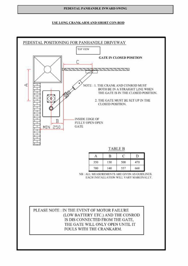
WALL MOUNT OUTWARD SWING
TOP VIEW
SIDE VIEW
USE SHORT CRANK-ARM AND LONG CON-ROD

SETTING UP THE LIMIT SWITCHES.
There are two micro switches “limit switches” in each motor. The function of the limit switches is to stop the motors turning when the limit switch is struck. The “Limit Rotors” are connected to the main shaft, these rotors strike the limit switches and the motor stops. There are two diodes across the switches, this is to allow the motors to turn in the opposite direction when triggered to do so. The first step in setting up the limit switches is to establish the closing direction of the motors. The motors will automatically drive to the closed position when first powered-up. When power is first applied to the motors, take note of the direction that the shaft turns, this will indicate the closing direction. NOTE. If it is determined that the motors are turning the correct way , continue to set up the limit switches as shown on page 16.If it is determined that the motors are not turning the correct way, complete the following steps before continuing to page 16.
1.Remove the power. Reverse the motor wires at the limit diodes as shown below.
After completing the above steps, the motors should be running in the correct direction i.e. When the CLOSE L.E.D. is on, the gates must be closed. When the OPEN L.E.D. is on the gates must be open. Continue setting up the limit switches as per page 16.
In order to reverse the motor direction, reverse these two wires
WIRING THE SLAVE MOTOR
When wiring the slave motor, it is important to note that the cable between the two motors must be minimum 2.5 mm cable and that the cable must be run in a conduit. Ensure that the cable is connected in the correct order. The cable must be connected from the P.C.Board output labeled SLAVE, to the limit switch diodes on the slave motor. The cable that is connected to the “A “output must be connected to the “A” input on the limit switch diodes. And the “B” output must be connected to the “B” input. See diagram below.
A B
Main P.C. Board on the master motor Limit switch diodes on the slave motor
SLAVE MASTER A B A B
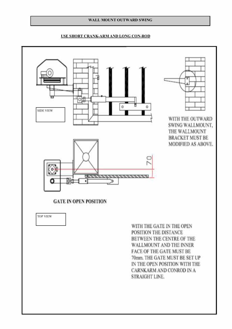
SETTING THE LIMITS
Step 1. Ensure that the motors are turning in the correct direction . Stand the battery up in a vertical position to allow access to the limit rotor
Step 2. Apply battery power. The motors will automati-cally turn until the closed limit is struck. If the motors are turning the wrong way, see page 15 in order to set the motors up in the correct direction.
Using the diagrams on pages 10 –14 the gates must now be placed in the closed position and the crank arms must be tightened. (23mm spanner.)
NOTE ensure that the gates are fully open before tighten-ing the crank arm as it can be difficult to loosen the crank arm after tightening due to the tapper shaft fitting. Check diagrams on page 10—15 to ensure correct positioning.
23 mm spanner to tighten crank arm
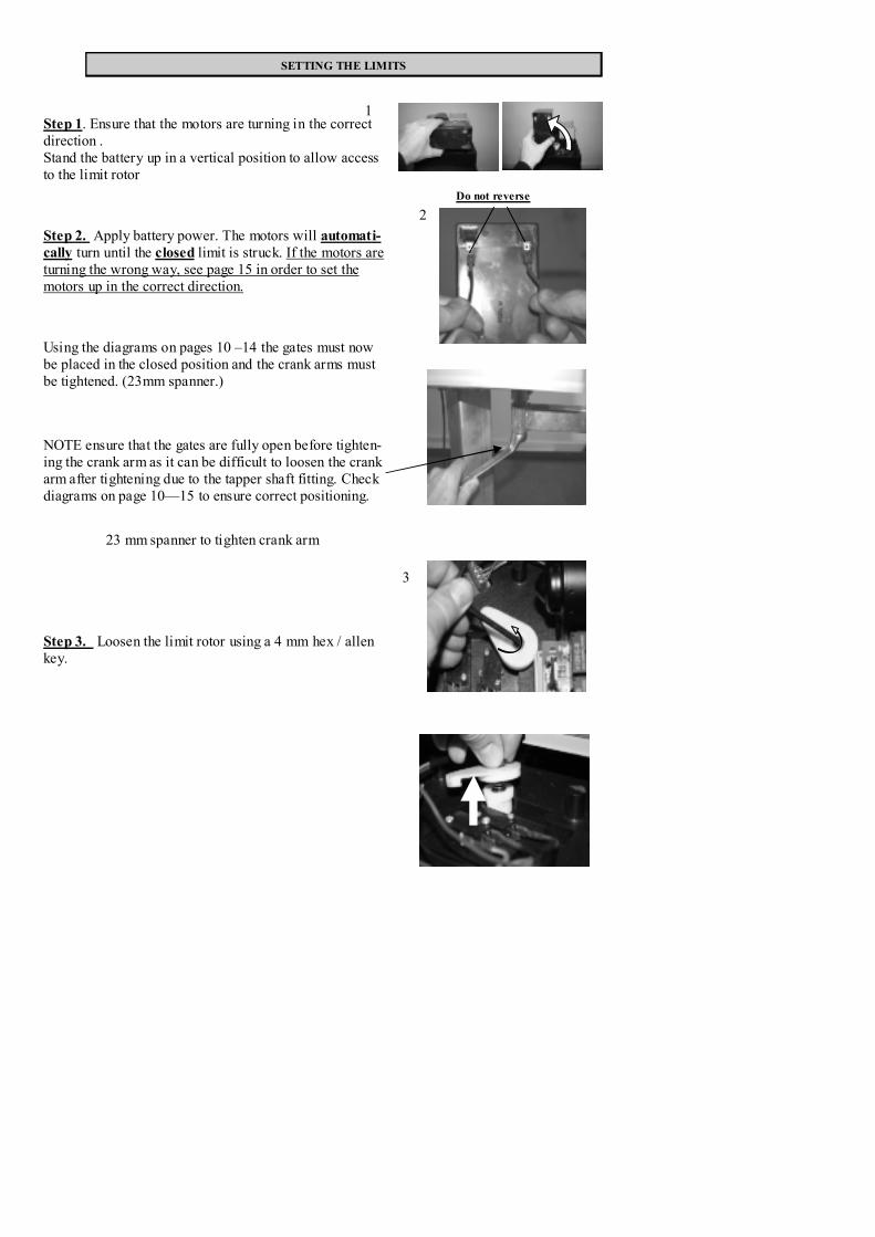
Step 3. Loosen the limit rotor using a 4 mm hex / allen key.
1
3
2Do not reverse

4
5
6
When gate reaches the desired open position, press the limit switch. To stop the motor. The limit switch can be released when the motors have stopped.
Step 4.Press the trigger button. The gates will start opening, .
Step 5. Lift and turn the rotor until it presses on the limit switch. See picture 6 below.
Step 6. Tighten the rotor using the 4mm Allen key. Do not over-tighten the cap-screw. The limit switches are now set and the gates can now be operated as nor-mal.
Rotor on open limit switch. Rotor must be in this position when the gates are fully open.
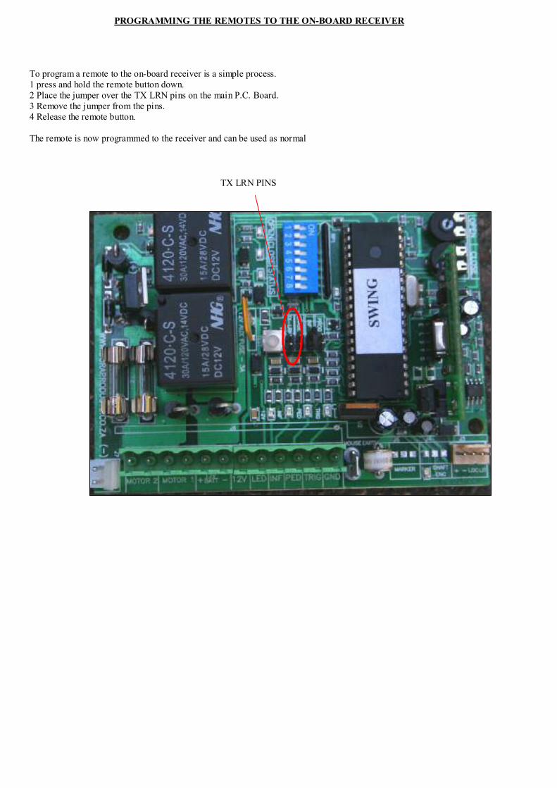
PROGRAMMING THE REMOTES TO THE ON-BOARD RECEIVER
To program a remote to the on-board receiver is a simple process. 1 press and hold the remote button down. 2 Place the jumper over the TX LRN pins on the main P.C. Board. 3 Remove the jumper from the pins. 4 Release the remote button. The remote is now programmed to the receiver and can be used as normal
TX LRN PINS

CONTROLLLER CONNECTIONS
The following connectors are found on the connector block on the main P.C.BOARD NB Ensure that all power is disconnected from the P.C.BOARD before any connections are made. Failing to do this will result in electrical shorts and major damage may occur to the P.C.BOARD. M1 and M2. These two connectors are high current 12 V DC outputs. These deliver current to the motors. 12 V + / - . These are the 12 volt 7 amp/hour Ni –Cad battery connectors. They supply the power to the P.C.CBOARD and the motors. It is very important that the battery is connected the correct way. Failure to do so will result in ma-jor damage to the P.C.BOARD. The positive battery lead (red) is connected to the positive (+) connector. The negative battery lead (black) is connected to the (-) connector. 12v. This connector is used to supply 12V DC to any auxiliary equipment used i.e. intercom , receiver, infra-red beams e.t.c. There is a 3 amp re-settable fuse for protection. (see wiring diagrams for more details on wiring auxiliary equip-ment ). L.E.D. This connector can be used to connect a remote Light Emitting Diode (LED)(OPTIONAL) The anode (+) must be connected to the L.E.D. connector and the cathode (-) must be connected to the GND connector. The remote L.E.D. will give the same indication as the STATUS L.E.D. on the P.C.BOARD. INF. This connector is used to connect infra-red beams to the motor. (OPTIONAL) The beams will work in the follow-ing manner. If the gate is closing and the beam is broken, the gate will stop and re-open. If the gate is opening and the beam is broken it will have no effect on the gate. (see wiring diagrams for more details on wiring infra-red beams) PED . This connector is to accommodate a pedestrian trigger. (OPTIONAL) This allows the gate to open partially. The opening distance is pre-set and can not be changed. When the pedestrian trigger is used the gate will open partially and will close automatically after 6 seconds. TRIG. This connector is the FULL TRIGGER input, this will open the gate fully. This is normally used for the receiver and /or intercom trigger. The trigger input has various actions when used. The following will happen when a trigger input is received. • If the gate is closed—the gate will open all the way. • If the gate is open. — the gate will close all the way. • If the gate is closing . — the gate will stop and re-open all the way. • If the gate is opening .— the gate will stop. GND. This connector is used as a common ground for all auxiliary equipment.
CONNECTOR BLOCK

CONNECTING THE RECEIVER (optional)
NOTE. When connecting any auxiliary equipment to the P.C.BOARD ensure that ALL power is removed from the P.C.BOARD.
Most auxiliary equipment is connected using Communication Cable, normally called “Comm’s Cable.” This is available in different sizes. The most common sizes are 8 core and 10 core cable. This is a single outer sheath with 8 or 10 solid individually coated copper wires inside. Each wire has a different colour. Care should be taken when using Comm’s cable as it can be broken easily. CONNECTING A RECEIVER. Connected to the P.C.BOARD in the following manner. Using a multi core communication cable or similar. Connect the 12v/ 24v wire to the 12v output on the P.C.BOARD. Connect the negative wire to the GND on the P.C.BOARD. Connect the N/O (normally open) wire to the TRG on the P.C.BOARD. The COM and NEG on the receiver must be “looped” (JOINED) Programming remotes to the receiver.1. Press and hold the button down on the remote. 2. While holding the button down, place the jumper over the two LEARN pins on the receiver. 3. Remove the jumper. 4. Release the button on the remote
PEDESTRIAN OPERATION A separate receiver, key-switch or key-pad must be connected in order to operate the gate in the pedestrian mode. The connection is done in the same manner as the above diagram with the exception of the N/O connection, as this connection must be connected to the PED connector on the main P.C.BOARD. In pedestrian mode the gate will open partially and then close automatically after 6 seconds.
NB the NO connector is wired to the TRIG connector on the Main P.C. Board
LEARN PINS

There are eight dipswitches found on the main P.C.BOARD.
The dipswitch settings on the swing motors are as follows:
NO 1. Must be Off for swing motors.
NO 2. The CURRENT SENSING dipswitch is used to operate in the high or low current range.
If the switch is on it will operate in the high current range i.e. for a heavy gate.
If it is off it will operate in the low current range (light to medium weight gate)
NO 3. This switch is the MULTIUSER Mode dipswitch, this must be selected when the motor is in a complex / multi-
ple user type environment. This allows only one trigger at a time when the gate is opening. NOTE Auto-close
must be selected for this switch to work. (SEE BELOW)
NO 4. BLANK . NOT USED.
NO 5–8. These are the AUTO-CLOSE settings. They can be operated individually or in sequence. (SEE TABLE BE-
LOW)
It should be noted that it is not safe to select AUTO-CLOSE without infra-red beams installed.
Auto-Close Switch 5 Switch 6 Switch 7 Switch 8
5 Sec ON OFF OFF OFF 10 Sec OFF ON OFF OFF 15 Sec ON ON OFF OFF
20 Sec OFF OFF ON OFF 35 Sec ON ON ON OFF 40 Sec OFF OFF OFF ON
75 Sec ON ON ON ON
DIPSWITCH SETTINGS
DIPSWITCHES

L.E.D. OPERATIONS.
STAUS— this L.E.D. has a number of functions it displays the following . Flashing once every two seconds = gate closed and AC power is connected. Flashing once per second = gate moving. On solid (no flashing) = gate open. Off = AC (mains) power disconnected. CLOSE — this L.E.D. is on when the gate is closing or is in the closed position. OPEN — this L.E.D. is on when the gate is opening or is in the open position. GREEN L.E.D. — this L.E.D. is on when the AC power (mains) is connected. If this light is not on the battery will continue to operate the gate, but the battery will eventually run down and the gate will stop working. This LED must be on at all times. TRG– this L.E.D. indicates that a trigger signal has been detected, the L.E.D. will flash when the remote is pushed. If this light is on solid, this indicates a possible fault in one of the trigger wires, i.e. intercom, receiver etc. PED– this LED is the same as the trigger LED bur it indicates the pedestrian trigger only. INF– this LED indicates the infra-red safety beam has been triggered, the LED will go off when a vehicle or pedestrian crosses the beam. If this LED is off continuously, this indicates a possible fault with the beams or the wires that connect the beams. 12V– this LED indicates that the 12 volt out-put is working, if this LED is not on, it indicates that 3 amp re-settable fuse has blown. In this case the power must be removed from the board and then re-connected to the board. This will re-set the fuse and normal operation can continue.
L.E.D OPERATION. AND MOTOR DIRECTION
CHECKING MOTOR DIRECTION.
The DURA SWING motors are set to default to the CLOSED position when power is received for the first time. This means that when the battery is connected to the P.C.BOARD the motors will turn until the closed limit switch is struck, . The closed L.E.D. on the P.C.BOARD will be on. If the gate is not in the same indicated position as the L.E.D. display on the P.C.BOARD i.e. gate open when close L.E.D. is on. Then the crank arm must be loosened and the motor must be triggered. This will allow the motor to turn while the gate does not move. Allow the motor to turn all the way until the limit switch is struck. The L.E.D. should now show the actual gate position. i.e. gate open and the open L.E.D. is on. When the gate is in the corresponding position in relation to the L.E.D. the crank arm must be tightened again.
LEDS

OTHER FUNCTIONS
PARTY MODE. (AUTO-CLOSE OVERRIDE) This allows the auto-close function to be over- ridden. This function is normally used when higher than normal traffic volumes are expected. To operate the party mode set up: Push and hold the trigger button until the gate starts to open. Release the trigger. The gate will now stay open until it is re-set into normal operating mode. To re-set the gate into normal operating mode: push the trigger twice within three seconds. The gate will now operate as normal. OVER-CURRENT SENSING. The P.C.BOARD is designed to detect OVER-CURRENT this means that if the gate hits an object or is stuck by some other means, the gates will stop driving. The results of an OVER-CURRENT are different, depending on what the gate is doing at he time of the OVER-CURRENT. If the gate is closing and an OVER-CURRENT is detected, the gate will stop and then re-open. If the gate is opening and an OVER-CURRENT is detected, the gate will stop and will not move until it receives an other trigger or the auto-close time is reached. If the gate senses an OVER-CURRENT 5 times in succession, the gate will stop working regardless of any trigger. To re-set the gate the AC power must be disconnected for 5 seconds then re-connected. The gate will operate as normal.
SETTING THE OVER-CURRENT SENSITIVITY.
The sensitivity of the over-current is set in the factory, this can be adjusted, but it is advised that this is only done if it is necessary. It must be noted that if the sensitivity is decreased, the gate will drive harder when an object is encountered, this means that damage or injury to a vehicle / pedestrian will increase if sensitivity is decreased. This should only be done if the gate over-currents without striking an object or is not being jammed by any other means. Before adjusting the sensitivity check that the gate is operating cor-rectly. i.e. hinges rusted, branches or garden growth hindering operation etc. To set the over-current sensitivity: there are two “POTS” found on the P.C.BOARD. One pot is to set the open sensitivity and the other is to set the close sensitivity. To decrease sensitivity, (heavy gate) using a small flat screwdriver, turn the pot clockwise. The adjustment should be done in very small increments. Until the desired sensitivity is achieved. Us extreme caution when setting the pots, as this can cause severe injury or damage if the sensitivity is set to low. To increase sensitivity, (light gate) turn the pot anti-clockwise. Take care not to set the pot too sensitive as this may cause the gate to over-current due to other external forces such as wind etc.
SWING
Potentiometers (pots). Turn to increase or decrease sensitivity of the motor. Note this will not alter the speed of the motor

CONNECTING INFRA-RED BEAMS.It is strongly recommended that infra-red beams are installed and connected to all automatic gates. If auto-close is to be selected it is essential that infra-red beams are used for safety reasons. To connect infra-red beams: Set the beams up so that they are directly across the driveway and are level with each other. The beams consist of a transmitter and a receiver. Remove the front covers and the boards will be visible. The receiver has 5 connections on the board , they are GND . 12V. COM. N/C. .and N/O. The transmitter beam has only two connections, they are GND and 12V. It is important that the covers do not get mixed up as the lenses are specific to the transmitter and receiver.
Wiring the infra-red beams: Using a multi core communication cable or similar. Connect the wire from the GND on the receiver beam to the GND on the main P.C.BOARD. Connect the 12v on the receiver beam board to the 12v on the main P.C.BOARD. Connect the N/C (normally closed) on the receiver beam board to the INF on the main P.C.BOARD. Connect the GND on the receiver beam board to the GND on the transmitter beam board. Connect the 12v on the receiver beam board to the 12v on the transmitter beam board. Connect the COM on the receiver beam board to the GND on the receiver beam board. (loop)
CONNECTING AUXILARY EQUIPMENT (optional)
BEAMS JUMPER on main PCB To be removed before beams are connected.
NB Beams shown with front covers removed. Covers must be in place when beams are active.
12 VOLT
GROUND
Receiver Transmitter

CONNECTING AUXILARY EQUIPMENT (optional)
This is the recommended method for wiring double beams in swing installations. This is to stop the gate closing even if the vehicle is past the first set of beams but it may still be in the path of the closing gate.
Main P.C.Board
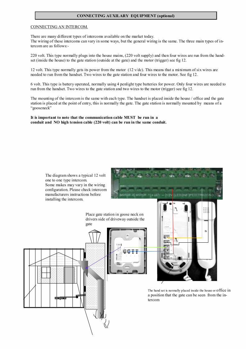
CONNECTING AN INTERCOM.
There are many different types of intercoms available on the market today. The wiring of these intercoms can vary in some ways, but the general wiring is the same. The three main types of in-tercom are as follows:- 220 volt. This type normally plugs into the house mains, (220 volt supply) and then four wires are run from the hand-set (inside the house) to the gate station (outside at the gate) and the motor (trigger) see fig 12. 12 volt. This type normally gets its power from the motor (12 v/dc). This means that a minimum of six wires are needed to run from the handset. Two wires to the gate station and four wires to the motor. See fig 12. 6 volt. This type is battery operated, normally using 4 penlight type batteries for power. Only four wires are needed to run from the handset. Two wires to the gate station and two wires to the motor (trigger) see fig 12. The mounting of the intercom is the same with each type. The handset is placed inside the house / office and the gate station is placed at the point of entry, this is normally the gate. The gate station is normally mounted by means of a “gooseneck” It is important to note that the communication cable MUST be run in a conduit and NO high tension cable (220 volt) can be run in the same conduit.
CONNECTING AUXILARY EQUIPMENT (optional)
The diagram shows a typical 12 volt one to one type intercom. Some makes may vary in the wiring configuration. Please check intercom manufacturers instructions before installing the intercom.
The hand set is normally placed inside the house or office in a position that the gate can be seen from the in-tercom
Place gate station in goose neck on drivers side of driveway outside the gate

NOTE. Ensure that all power is switched off before any connections are done. The light lock card is plugged on to the main P.C. Board. It is designed to operate pillar lights and /or an electric lock whenever the P.C. Board receives a trigger. The lights will remain on for a period of four minutes. There is an option which allows a switch to be connected to the light / lock card to switch on the lights for as long as is required. This is called the toggle switch The lock section is applicable on swing gates only. The lock type can be selected by placing the jumper over the relative pins marked MAG / STRIKE. Please note that Magnetic locks require a dedicated power supply.
LIGHT / LOCK WIRING DIAGRAM. (optional) NOTE. The lock feature is for use on swing gate installations only
TOGGLE SWITCH mounted in the house Use to switch lights on manually (optional)
220volt POWER SUPPLY
POWER SUPPLY. See lock manufactures Specs on power supply
STRIKE / MAG LOCK mounted on the gate
Lock type selection pins
Light /lock card plugs di-rectly onto the main P.C.Board
SWIN
G
Wiring diagram for external status L.E.D. (optional )An external status L.E.D. can be connected to the P.C.B. this L.E.D. will indicate the status of the gate . The L.E.D. can be fitted to the intercom or any other convenient place. SEE PG 21 for L.E.D. indications
5mm leaded L.E.D.
LIGHT

CONNECTING A FREE EXIT LOOP DETECTOR (optional)
A loop detector is used to automatically open the gates when a vehicle approaches the gates. It is recommended that a DuraLoop detector is used when a free exit loop detector is required. However it is important to note that the manufacturers installation and wiring is followed when installing the loop detector. It is extremely important that the loop is placed in such a way that the vehicle that triggers the loop is not in any way within the opening arc of the gates as this will cause damage to the vehicle if the gates strike the vehicle. Number 3 dipswitch on the main P.C. Board MUST be ON when using a loop detector. This will avoid a second vehicle triggering the gates closed
Opening arc to be clear when vehicle is on loop
Twisted wires to trigger. See loop manufacturers wiring specs
Loop detector buried in driveway

FAULT REASON ACTION
Gates open slightly then close automati-cally or gate closes in small jerking mo-tion
Battery flat Check charger card or transformer or replace old battery.
One gate does not operate at all or oper-ates erratically
Motor fuse (8 amp) blown or micro switch faulty
Replace 8 amp fuse or replace micro switch.
Gates stop when closing and then re-open automatically.
Over current.= Gate jamming. Check gate / hinges / con rod / crank arm. Return to manufacturer for repairs.
Gates opens without any trigger input. (opens on its own)
Neighbour has same transmitter code Motor wires are the wrong way.
Change code on transmitters and receiver or change motor direction. (see pg 15)
Gates are jammed and will not move at all.
General shut down. Remove all power and re-connect power.
Gates do not operate from the remote but will operate using the test button on the p.c.board.
Receiver faulty or loose wire connection or 3 amp fuse blown on p.c.board.
Replace receiver or tighten wire connections or replace fuse.
Fault findingIt is important to note that a multi-meter must be used when fault finding in order to get an accurate reading of voltages and to check fuses. Most problems are simple to fix, this normally requires a systematic approach. The correct voltages that should be found are as follows:- A/C power onto the charger card = 16v/ac D/C power coming off the charger card = 14.2v/dc D/C power at the battery leads = 13,8v/dc D/C power on the battery (no load) = +/- 13v/dc D/C power on battery (with load) = < 1 volt drop on no-load reading. A voltage drop of no more than one volt must be allowed when running the motor. If the voltage drop is more than one volt, the bat-tery may need replacing.
D.A.C.E. products carry a TWO year WALK -IN warranty. The following conditions apply:- • Warranty covers factory faults only. • Warranty covers the following items. Electric motor, gearbox, P.C.Board, Pedestal, crank arm and con-rod. • Warranty does not cover the following. Lightning , Power surges (power outages ), flooding, insect infestation, Vehicle damage or
incorrect installation as laid down by D.A.C.E. • Warranty is void if any attempt is made to repair / modify or change the motor , P.C. board e.t.c. Unless authorised by D.A.C.E. • The product MUST be returned to D.A.C.E. for inspection before any warranty claim will be entered into. • Due to power fluctuations / outages, the transformer is not guaranteed in any way.
WARRANTY