
Swift 3D V4.5 User Guide -...
287
Swift 3D V5 User Guide
Transcript of Swift 3D V4.5 User Guide -...

Swift 3D V5 User Guide

CopyrightThis manual and the software described within its pages are furnished under license and may only be used or copied in accordance of the terms of such license. Program copyright 2007 Electric Rain Inc. User Guide copyright 2007 Electric Rain Inc. All rights reserved. No part of this manual may be reproduced in any form or by any means without the expressed written consent of Electric Rain, Inc. Translation: It's ours and you can't have it! THTHPPPT! Unless you say "pretty please."
Electric Rain, Inc.5171 Eldorado Springs Drive
Boulder, CO 80303www.erain.com
TrademarksSwift 3D, the Swift 3D logo, ZAM 3D, the ZAM 3D logo, RAViX and Crystal Trackball are trademarks of Electric Rain Inc. Electric Rain reserves the right to seize all your assets…Hey, what are you doing reading this ridiculous fine print. OK, you caught us. We'll keep it legal. Microsoft, Windows, Windows 95, Windows 98, Windows NT, Win-dows 2000, Windows ME, Windows XP, Windows Vista, Microsoft Expression Blend and MS Visual Studio 2005 are trademarks of Microsoft Corporation. Adobe Photoshop, Illustrator, Flash, Freehand and Streamline are trademarks or registered trademarks of Adobe Systems Inc. All other product brand names are trademarks or registered trademarks of their respective holders. Translation: Make up your own stuff.
CreditsSwift 3D and ZAM 3D are masterminded by John Soucie, the RainMaker. To him we owe our existence. Electric Rain's helm is manned by Mike Soucie, RainMan. As for the rest of the Erainiacs who have come together in Boulder, Colorado to build software and enjoy life, it's been fun!
Much appreciation goes out to all the family members who have supported us through this journey.
The Swift 3D User Guide was penned by Nicholas Petterssen - RainWriter.Revisions and Amendments to the guide for Swift 3D V5 by Kris Honeycutt - Savant.Revisions and Amendments to the guide for ZAM 3D V1 by Christine Petterssen.
Cover artwork and all ERAIN print design was masterminded by Jeff Schaich, the best damn designer ever.
Thanks Y'all!

Swift 3D V5 User Guide
BIG SHOUT-OUT TO OUR USERS!
You know who you are, and we know where we'd be without you (to put it bluntly nowhere!) Electric Rain has accu-mulated what we believe to be the highest quality user base in the history of software, and everyday we all go to work it's because we enjoy building stuff that makes you happy, and in turn getting feedback from happy people. Yes, it all sounds a little sappy, but honestly we are all greatly appreciative of the types of people who are into creating 3D for Flash and we value the fact that we can pursue our passions in software with folks like yourselves who pursue Flash design with equal passion.
As we enter Phase Five phase of this journey, we want to personally thank those people who comment on the way we go about the business of documentation. Now we'd like to also offer you all some gratitude from our Technical Support department since they have jumped onboard in our efforts to provide high quality and personable resources to our users. This User Guide is a joint effort on our behalf to provide you with both the initial educational aspect of learning Swift 3D, but also the post educational support you might be seeking once your feet get wet in the waters of 3D.
With that in mind, you'll find that aspects of our documentation continue to evolve. The products of this growth can be found on the Electric Rain website (www.erain.com) in the form additional step-by-step instructions on specific tasks, rich-media tutorials that directly correlate with topics in the User Guide, as well as the expected thorough coverage of features and their use. This ongoing synthesis is made possible only through the exemplary dedication of Electric Rain’s stellar support staff and through the contribution of educational materials from our talented community of users.
Much Thanks,
Team Erain


Swift 3D V5 User Guide
Table of ContentsChapter 1: What Swift 3D Is All About ...................................................... 1
How did we get here? ........................................................................................................................1A workflow for everyone ....................................................................................................................2
Building 3D Models ...................................................................................................................2Creating 3D Scenes ..................................................................................................................3Rendering 3D Output ................................................................................................................4Integrating 3D Content ..............................................................................................................5
Chapter 2: Getting Up and Running .......................................................... 7Welcome to the ERAIN world ............................................................................................................7Some thoughts about this User Guide ...............................................................................................7Installation ..........................................................................................................................................8
What you absolutely need to run Swift 3D ................................................................................9Puttin' this puppy on your unit ...................................................................................................9
Additional Resources .........................................................................................................................10“What the #@&?% is going on?” (Tech Support) ..............................................................................11Web Assistant ....................................................................................................................................13
Chapter 3: Scene Editor ............................................................................. 15Overview ............................................................................................................................................15Swift 3D Interface ..............................................................................................................................16Customizing the Swift 3D Interface ....................................................................................................17User Preferences ...............................................................................................................................18
Editor Tabs ................................................................................................................................18Extrusion Editor .........................................................................................................................19Lathe Editor ...............................................................................................................................20Advanced Modeler ....................................................................................................................20Preview and Export Editor ........................................................................................................20Web Assistant ...........................................................................................................................20
Scene Editor ......................................................................................................................................21Viewports ..................................................................................................................................21Properties Toolbar ....................................................................................................................22Main Toolbar .............................................................................................................................23Animation Toolbar .....................................................................................................................24Rotation Toolbar .......................................................................................................................25
i

Table of Contents
Lighting Toolbar ........................................................................................................................25GalleryToolbar ..........................................................................................................................26Gallery Management .................................................................................................................26
Chapter 4: Tutorial ...................................................................................... 31Chapter 5: Viewport Properties ................................................................. 49
Layout Properties ...............................................................................................................................49Layout .......................................................................................................................................49
Display Modes ...................................................................................................................................51Orthographic View ....................................................................................................................52
Environment Properties ....................................................................................................................53Background Color .....................................................................................................................53Ambient Light Color ..................................................................................................................54Environment ..............................................................................................................................55
Chapter 6: Working With Objects .............................................................. 57Object Property Page ........................................................................................................................57
Name ........................................................................................................................................58Hide ...........................................................................................................................................58Lock ..........................................................................................................................................59Refraction Index ........................................................................................................................59Preserve V3 Texture Coordinates .............................................................................................59Smoothing .................................................................................................................................60
Rendering Options .............................................................................................................................60Mesh Morpher ....................................................................................................................................60Selecting Objects ...............................................................................................................................60
Selecting Individual Objects ......................................................................................................61Selecting Multiple Objects .........................................................................................................61Selecting Objects Using Hierarchy Toolbar ..............................................................................61
Grouping Objects ...............................................................................................................................61Cutting, Copying, Pasting and Deleted Objects .................................................................................62Positioning Objects ............................................................................................................................63
Click-and-Drag ..........................................................................................................................63Nudge Keys ..............................................................................................................................63Constrain Axis ...........................................................................................................................64Numerical Positioning ...............................................................................................................64
Pivot Points ........................................................................................................................................66Rotating Objects ................................................................................................................................67
Numeric Rotation ......................................................................................................................68
ii

Swift 3D V5 User Guide
Scaling Objects ..................................................................................................................................69Scaling Mode ............................................................................................................................69Scale Property Page .................................................................................................................70
Hierarchy ...........................................................................................................................................71Creating Parent/Child Relationships .........................................................................................71Groups Within Hierarchy ...........................................................................................................72
Chapter 7: Primitives .................................................................................. 73Inserting Primitives ............................................................................................................................73Sphere ...............................................................................................................................................74GeoSphere ........................................................................................................................................74Box (Cube) .........................................................................................................................................75Pyramid ..............................................................................................................................................75Cone ..................................................................................................................................................76Cylinder ..............................................................................................................................................77Torus ..................................................................................................................................................77Plane ..................................................................................................................................................78Polyhedron .........................................................................................................................................78
Chapter 8: Text ............................................................................................ 83Inserting a Text Object .......................................................................................................................83Text Property Page ............................................................................................................................83Bevels Property Page ........................................................................................................................85Sizing Property Page .........................................................................................................................87Editing Characters Individually ..........................................................................................................87Convert Text to Paths ........................................................................................................................87Working With Text Objects in Advanced Modeler .............................................................................88
Chapter 9: Extrusion Editor ....................................................................... 89How It Works .....................................................................................................................................90Main Toolbar ......................................................................................................................................90Working with Extrusions from the Model Gallery ...............................................................................92The Grid .............................................................................................................................................93Creating Shapes ................................................................................................................................93Editing Your Artwork ..........................................................................................................................95
Editing Points ............................................................................................................................95Editing Paths .............................................................................................................................96
Working with complex shapes ...........................................................................................................98Combining and Breaking Apart ..........................................................................................................98
iii

Table of Contents
Editing Imported AI and EPS Extrusions ...........................................................................................100Path Morphing ...................................................................................................................................100Extrusion Properties ..........................................................................................................................100Working With Extruded Objects in Advanced Modeler ......................................................................101
Chapter 10: Lathe Editor ............................................................................ 103How It Works .....................................................................................................................................103
Creating a Lathed Object ..........................................................................................................104Working With Lathes from the Model Gallery ....................................................................................105Copying and Pasting from the Extrusion Editor .................................................................................106Lathe Property Page ..........................................................................................................................106Lathe Path Morphing .........................................................................................................................107Working with Lathes in the Advanced Modeler ..................................................................................107
Chapter 11: Importing AI and EPS ............................................................ 109How to do it ........................................................................................................................................109
Materials of Imported AI and EPS Files ....................................................................................110Layers (Depth Progression) ......................................................................................................110
Editing Your Imported AI and EPS Artwork .......................................................................................111Tips for building vector artwork ..........................................................................................................111Troubleshooting AI/EPS Import Problems .........................................................................................114
Chapter 12: Importing 3DS and DXF ......................................................... 1153DS File Format .................................................................................................................................115DXF File Format ................................................................................................................................117
Chapter 13: Advanced Modeler ................................................................. 119Overview ............................................................................................................................................119
When to use Swift 3D's standard modeling tools: .....................................................................120When to use Swift 3D's Advanced Modeler: .............................................................................120When to use them both: ............................................................................................................120
3D Terminology 101 ..........................................................................................................................120Polygons ...................................................................................................................................121Normal ......................................................................................................................................122
Moving Between Scene Editor and Advanced Modeler .....................................................................122Scene Editor to Advanced Modeler ..........................................................................................122Advanced Modeler to Scene Editor ..........................................................................................123
Modeler Default Settings ...................................................................................................................123Working With the Viewports ...............................................................................................................123
iv

Swift 3D V5 User Guide
Customizing Viewport Layout ....................................................................................................123Viewport Menu Button ...............................................................................................................123Reference Grid ..........................................................................................................................124Axis Guide .................................................................................................................................124
Viewports ...........................................................................................................................................1242D Orthographic Viewports .......................................................................................................125Perspective Viewport ................................................................................................................125Viewport Display Modes ............................................................................................................126
Edit Mesh Button ...............................................................................................................................126Combining and Breaking Apart Meshes ............................................................................................127Starting with Gallery Models or Primitives .........................................................................................128
Model Gallery ............................................................................................................................129Primitive Meshes ...............................................................................................................................130
Inserting Primitives ....................................................................................................................130General Properties .............................................................................................................................131Selection ............................................................................................................................................132
Select Tools ..............................................................................................................................132Selection Property Page ...........................................................................................................136Edit Menu ..................................................................................................................................139
Surface Groups ..................................................................................................................................141Transform Tools - Move, Rotate, Scale and Extrude .........................................................................143
Selecting Transform Tools ........................................................................................................143Move ..................................................................................................................................................145
Move Tool .................................................................................................................................146Move Tool Property Page ........................................................................................................146
Rotate ................................................................................................................................................147Rotate Tool ...............................................................................................................................147Rotate Property Page ...............................................................................................................148
Scale ..................................................................................................................................................149Scale Tool .................................................................................................................................149Scale Tool Property Page .........................................................................................................149
Extrude ..............................................................................................................................................150Extrude Tool ..............................................................................................................................151Extrude Tool Property Page ......................................................................................................151
Align To ..............................................................................................................................................152Mirror .................................................................................................................................................152Flatten ................................................................................................................................................153Roundness .........................................................................................................................................154Subdivide ...........................................................................................................................................155
Delete Empty Faces ..................................................................................................................156
v

Table of Contents
Edge ..........................................................................................................................................156Weld ..........................................................................................................................................158SmartWeld ................................................................................................................................158
Smoothing Groups .............................................................................................................................159Mesh Morpher ....................................................................................................................................162Bitmap Texture Mapping ....................................................................................................................164
Chapter 14: Materials .................................................................................. 167The Material Gallery ..........................................................................................................................168
Vector Materials ........................................................................................................................168Raster Materials ........................................................................................................................169Applying Materials .....................................................................................................................170
Material Property Page ......................................................................................................................171Material Editor ....................................................................................................................................172
Creating and Editing Materials ..................................................................................................173Solid (Vector) Colors .................................................................................................................173Bitmap Textures ........................................................................................................................175Procedural Color Mapping ........................................................................................................177Procedural Texture Mapping .....................................................................................................178Transparent Materials ...............................................................................................................179Reflective Materials ...................................................................................................................180Environment ..............................................................................................................................181
Chapter 15: Lighting ................................................................................... 183Types of Lights ..................................................................................................................................184Lighting Gallery ..................................................................................................................................184Trackball Lighting ...............................................................................................................................185
Positioning Trackball Lights ......................................................................................................185Adding and Subtracting Trackball Lights ...................................................................................186
Scene Lights ......................................................................................................................................186Free Lights ................................................................................................................................186Target Lights .............................................................................................................................186
Light Properties ..................................................................................................................................188Hierarchy ...........................................................................................................................................189
Chapter 16: Cameras .................................................................................. 191Standard Cameras .............................................................................................................................192
Camera Mode ...........................................................................................................................192Default Target Camera .............................................................................................................193
vi

Swift 3D V5 User Guide
Scene Cameras .................................................................................................................................195Free Cameras ..........................................................................................................................196Target Cameras ........................................................................................................................196
Camera Property Page ......................................................................................................................197Rendering Camera Views ..................................................................................................................198
Chapter 17: Animation ................................................................................ 199Animate Button ..................................................................................................................................200Animation Timeline Toolbar ...............................................................................................................200Animation Gallery ..............................................................................................................................203
Saving an Animation to the Animation Gallery ..........................................................................204Keyframe Animation ..........................................................................................................................205
Editing Keyframes and Animations ...........................................................................................207Editing the Animation Path ........................................................................................................208
Animating Scale .................................................................................................................................210Animating Materials ...........................................................................................................................211Animating Lights ................................................................................................................................211Animating Cameras ...........................................................................................................................212Hierarchical Animations .....................................................................................................................212Path Morphing ...................................................................................................................................213Mesh Morphing .................................................................................................................................214
Chapter 18: Preview and Export Editor .................................................... 217Previewing vs. Rendering vs. Exporting ............................................................................................217Render Preview .................................................................................................................................218Export To File ....................................................................................................................................220
Chapter 19: Rendering With RAViX ........................................................... 221Vector Output Options .......................................................................................................................221General ..............................................................................................................................................222
Target File Type ........................................................................................................................222Video File Formats ....................................................................................................................225Optimization ..............................................................................................................................227Detail Level ...............................................................................................................................229Save Render Settings ...............................................................................................................229
Fill Options .........................................................................................................................................230Edge Options .....................................................................................................................................235
vii

Table of Contents
Chapter 20: Rendering With EMO ............................................................. 241General ..............................................................................................................................................242
Target File Type ........................................................................................................................242Bitmap Compression .................................................................................................................243Color Depth ...............................................................................................................................243Antialias Quality ........................................................................................................................243
Chapter 21: Working With Exported Files ................................................ 245Publishing SWF files directly to Web .................................................................................................245SmartLayer SWFT Files using the Swift 3D Importer ........................................................................245
Swift 3D Importer ......................................................................................................................246Layers .......................................................................................................................................246Now the Fun Begins - Utilizing SmartLayer Technology ...........................................................248Updating Imported SWFT Files .................................................................................................249
SWF Files From RAViX — Standard Import ......................................................................................249Breaking Out to Layers .............................................................................................................249Optimizing in Flash ...................................................................................................................250
Raster Files from EMO — Standard Import .......................................................................................250Exporting 3DS Files ..........................................................................................................................251Export to Papervision3D ..................................................................................................................251
Appendix A: Menus .................................................................................... 255Scene Editor Menu System ...............................................................................................................255Extrusion and Lathe Editor Menu System .........................................................................................258Advanced Modeler Menu System ......................................................................................................258Preview and Export Editor Menu System ..........................................................................................260
Appendix B: Keyboard Strokes/Shortcuts ............................................... 263Scene Editor ......................................................................................................................................263Extrusion and Lathe Editors ...............................................................................................................265Advanced Modeler .............................................................................................................................266Preview and Export Editor .................................................................................................................267
Index: .......................................................................................................... 269
viii

Chapter 1 What Swift 3D Is All About
How did we get here?The answer to that question gets more and more complex through each version release of Swift 3D as our little 3D tool grows up to be a full-fledged 3D application. Here's a quick study of Swift 3D's history…
Swift 3D has always had a fairly clear focus in life, declaring unabashedly that it was all about creating quick and easy 3D for Flash. Furthermore, with its initial focus on vector output via the RAViX rendering engine, users typically came knocking on Swift 3D's door looking for one core solution - generating 3D vector animations.
But of course, things change.
As Flash's breadth grew, so did Swift 3D's, and before long we included a second rendering engine that provided the ability to output photorealistic raster output. And not to overlook its roots, we have continued our development efforts towards upgrading the vector output which bolstered RAViX's position as the industry's premier 3D vector rendering engine.
Meanwhile, back at the interface, Swift 3D has been introducing more and more modeling capabilities that suit our most abundant customers - people with lots of design skills but little 3D background. Tools were included that made the leap from 2D to 3D design as comfortable as possible for all those Flashers out there tantalized by the thought of easily creating 3D graphics and animations for their Flash projects.
And since no application is an island, Electric Rain has also spent significant time constructing easily accessible and fast-moving bridges designed to get your 3D content out of Swift 3D and into the world of Flash. When playing the role of a complimentary tool, we've felt it prudent to maintain a good working relationship with the application we compliment.
So that's 's illustrious past in a nutshell, which brings us back to the present day and the task at hand - trying to summa-rize our now mature and highly-potent 3D application in a few short pages of this User Guide. You see, as Swift 3D continues to develop in features and capabilities, so too does it develop in its utility. Whereas we used to be able to clearly define our typical user and his or her typical workflow, now Swift 3D is faced with a multitude of users coming into the application with a multitude of things they are trying to achieve.
Fortunately, this growing set of user variables and disparate end-games need not concern you. I am happy to report that although Swift 3D has developed an increasingly rich set of capabilities, it still does one thing really, really well - quickly and easily create 3D graphics and animation. And this is critical because whether you're a Flash designer, a 3D
1

Chapter 1 | What Swift 3D Is All About
artist, a 2D illustrator, a CAD professional or a Web design hobbyist, Swift 3D now provides ALL of the tools you need to get your mission accomplished in the least amount of time with the highest quality results.
A workflow for everyoneRegardless of your 3D experience or design intent, this chapter is included in order to help you get your arms around the concept of Swift 3D as quickly as possible. We're not here to answer specifics - those come later. We're here to look at the workflow and toolset in an "every-user" sort of way. And despite the diversity of goals our users now come into Swift 3D with, there is an underlying series of steps that everyone will end up moving through, regardless of your intended outcome. Here are those steps:
1. Building 3D models2. Creating 3D scenes3. Rendering 3D output4. Integrating 3D content
We'll go through these steps one at a time and point out some key functional areas of Swift 3D. At the same time I'll call attention to some of the areas that are new to Swift 3D V5 so those of you coming from an earlier version can get a better feel for where your upgrade investment lies.
1. Building 3D ModelsCreating 3D objects is at the core of any 3D application, but there are a variety of different strategies you can take within Swift 3D to populate your scene with these models.
Importing existing artwork and modelsSince many graphic designers have already spent time creating 2D vector artwork, one of Swift 3D's most convenient tools is the AI/EPS importer that instantly converts vector artwork into a 3D object. In addition, you can utilize the scads of free models available on the Web, or any existing 3D assets you or your clients already have, and bring them into Swift 3D in either the 3DS or DXF format.
Pulling from internal galleries Once something has been modeled, there's rarely ever a need to go through the "create-from-scratch" process again with that particular model. Swift 3D V5 includes a model gallery as well as a Bezier path gallery that come populated with pre-built artwork designed to expedite any modeling tasks at hand. And of course you can save your own cre-ations into these galleries as well as gather resources from fellow members of the Swift 3D community.
Using basic building blocks3D primitives are objects that serve as the fundamental building blocks for modeling. You can choose from a variety of primitive shapes, such as boxes, spheres, cones and even the occasional dodecahedron, which can be modified and assembled into more complex models. Or if you're looking for 3D text, Swift 3D will convert any TrueType or Post-Script font installed on your computer into a 3D model.
2

Swift 3D V5 User Guide
Drawing 2D shapes to create 3D objectsSince most of our users are pretty handy with a Bezier pen, Swift 3D serves up two modeling tools that use basic paths to create more complex 3D objects. The Extrusion Editor is designed to give your 2D paths both depth and bevels, and the Lathe Editor will convert your paths into radial 3D surfaces.
Advanced Modeling interfaceThis feature is less a modeling tool and more an entire modeling environment. When you've hit a point where the sup-plied shapes and your 2D drawing skills aren't going the full distance, the Advanced Modeler is here to take you the rest of the way to the land of total and complete modeling power and versatility. In this interface you have full editing control over the polygonal structure of your models as well as the ability to apply detailed textures to their surfaces through a UV texture coordinate system.
Adding colors and materials to your objectsWe don't live in a monochrome world, and neither should your models. Swift 3D provides a variety of tools to help you color and texture your creations. Whether it's dragging and dropping a supplied material from the galleries, editing an existing material to suit your needs or creating a bitmap or procedural texture from scratch, you'll have no problems surfacing your 3D creations for optimal visual impact.
2. Creating 3D ScenesAlthough 3D models comprise the basics of a project, they rarely serve as an ending point. Lights, cameras and anima-tion are usually integral parts of what is to become an entire 3D scene.
Using cameras to view your sceneSwift 3D comes equipped with a handful of standard cameras that serve as windows into your scene, and you won't have to know a thing about optics or cinematography to use them. But as you grow more comfortable with your skills you'll find that great visual effects can be created through the use of Scene Cameras, which are integrated with your scene and fully mobile, just like the cameras used to create big-time Hollywood movies.
Lighting your sceneAlthough you won't be forced to touch a single light bulb or switch, the world of lighting can get as rich as you care to make it. By editing existing lights, adding your own custom lights or even animating lighting schemes, you'll see that showing your scene in the best possible light is both easy and powerful.
And realizing that it's not everybody's dream to be a Key Grip, Swift 3D includes an entire Lighting Gallery full of pre-configured lighting schemes so you can harness the creative juices from the 3D gurus of the world. And when you step up to create your own illuminatory masterpiece, the gallery will be there with open arms to archive your creation for future use.
3

Chapter 1 | What Swift 3D Is All About
Animating objects within your scene
Advanced animation toolsWhen it's motion control you're looking for, Swift 3D hands over the wheel and says, “you drive.” Swift 3D offers full animation path editing through an in-scene Bezier curve editor, letting you map out precise object, camera and light animations. And it's a simple process to link both cameras and lights to other objects using Swift 3D’s Hierarchy sys-tem so cameras and lights can easily track objects throughout an animation.
If that isn’t enough to satisfy your requirements, Swift 3D has your blinking, bending, twisting, contortional needs cov-ered. No longer restricted to just animating entire objects, the Mesh Morpher provides you with the ability to animate the vertices of a solid mesh. With the option to animate your Advanced Modeler creations or even imported 3D models at your disposal, now masterpieces of motion that may have been previously difficult or even impossible to create can be achieved. For more information on the Mesh Morpher check out the chapters on Animation and the Advanced Mod-eler.
3. Rendering 3D OutputHerein lies the magic of transforming your 3D scene into a usable format. Depending on your production goals, Swift 3D is prepped and ready to render exactly what you need.
Creating vector content with RAViXIn its ongoing mission to please all vectorphiles of the world, the RAViX rendering engine lies at the heart of Swift 3D and is the single most common reason users have flocked to this application. RAViX is responsible for taking the 3D scene you have assembled within the Swift 3D interface and converting it to vectors. We can't tell you exactly how it does it, but we CAN tell you that the fourth incarnation of this ingenious technology offers signifcant speed advan-tages, shadow density controls, improvements to the realism of transparent materials, pen style outlines, enhanced SVG and EPS output, as well as popular movie file formats (AVI, FLV and QT). In essence, there are so many output variations that I have to refer you to the Rendering With RAViX chapter for the full details.
Creating raster content with EMODespite the beauty of scalable vector content, there's definitely a cap on the realism you can generate with RAViX, and thus the existence of EMO, Electric Rain's very own ray tracing raster rendering engine. And that long list of adjectives I just used can all be summed up in a single word - Photorealism. If you're shooting for 3D content that simply blows people away, EMO will get you there with its advanced light calculations and detailed bitmap material rendering. Besides the host of static image format options for export, we also give the option to export EMO rendered scenes to AVI, FLV and QT movie file formats.
Utilizing SmartLayer TechnologyEver since Flash MX stormed onto the scene with its extensibility architecture, Electric Rain has had the opportunity to get more creative in how RAViX renders files since Adobe provides us with the ability to go beyond the typical SWF import process. SmartLayer Technology works hand-in-hand with the Flash MX/MX 2004/8/CS3 Importer (see next section) to break apart your 3D scene into individual layers that can be automatically imported into Flash's Library.
4

Swift 3D V5 User Guide
This technology provides exceptional ease of integration with your Flash content, creates smaller files, allows for more design creativity and is highly recommended for anyone using Flash MX or higher.
4. Integrating 3D ContentSwift 3D is designed to be a content creation tool, not a content viewing tool. For this reason, anything you render from Swift 3D, whether using RAViX or EMO, will need to be displayed to your viewing audience using some additional tools or technology.
Distributing SWF files directlyOutput from Swift 3D in the SWF format, both vector and raster-based, can be viewed directly in two ways. First is if your viewers have the standalone Flash Player installed on their computers, which is typically only the case if those computers also have the Flash authoring tool installed as well. Second is the method of using a Web browser and its associated Flash Player plug-in to display SWF files from Swift 3D. Many of our users who have no post-production editing needs simply publish their Swift 3D-generated content to the Web using SWF files embedded in their HTML pages.
Importing SWF output into FlashA larger number of our users DO want to somehow further edit or integrate their 3D work in Flash, and the SWF for-mat provides an excellent vehicle for making the journey from Swift 3D to Flash. Both vector and raster renderings contained within an SWF file will be comprised of a series of keyframes (or a single keyframe if it's a single-frame ren-dering) that will arrive neatly onto Flash's timeline in their own separate layer upon import. For the raster-based SWF files there will be a series of images on that layer, and for vector-based files there will be a series of vector-based draw-ings made up of lines and fills, which can be further broken apart and edited on a frame-by-frame basis if needed.
Leveraging the Flash ImporterAs mentioned in the SmartLayer section, those using Flash MX and higher have the ability to use the included Flash Importer to transport files from Swift 3D to Flash via Electric Rain's .SWFT proprietary file format. Contained in these files is layered 3D content that the Importer interprets and places into Flash's library as a movie clip or directly onto the stage. The Flash Importer is installed automatically for you with Swift 3D when a compatible version of Flash is detected on your machine.
Using raster-based file formatsThe EMO ray tracer is well-versed with the standard raster file formats such as JPEG, BMP and PNG to name a few, as well as the AVI, FLV and QT movie file formats. When rendering to these formats you'll find that the files behave just like any other image/movie file you've worked with in the past. Whether publishing them directly to the Web, editing them further in Photoshop or Fireworks, or attaching them to an email, these files are about as universal as you get.
Using vector-based file formats besides SWFYes, Swift 3D tries to be as agnostic as possible when it comes to rendering output, so you'll find both AI and EPS as file types within the RAViX rendering options. These files can be imported into vector-based drawing applications like Illustrator and Freehand, making Swift 3D an excellent choice for creating 3D illustrations. Additionally we have
5
Chapter 1 | What Swift 3D Is All About
included the SVG and XAML formats as an option for those interested in these potentially powerful distribution for-mats. As with raster rendering, there is also the ability to export to the AVI, FLV and QT movie file formats.
Exporting True 3D DataAlthough not related to either of our rendering engines, this is a good place to mention that it is possible to export your Swift 3D creations in a true 3D file format for use in other applications. While we think Swift 3D is a pretty darn great program, we recognize that no program is an island and that the workflow of designers, animators and 3D enthusiasts are typically filled with a host of software packages. In a step to allow our users to fully set their creations free, Swift 3D includes the option to export individual objects or an entire scene to the popular 3DS file format. Checkout Chapter 21 for more information on generating 3DS files from Swift 3D.
3…2…1…That's it, you're now fully prepped and ready to move on to Phase 2 of the Electric Rain Experience. With both the his-tory of Swift 3D and its prescribed workflow in your back pocket you're set to begin your rapid climb to veteran Swift 3D status. Read on, learn more, play around and enjoy it all.
Now have at it!
(Seriously, that's it. Now get along. Shooo!)
6

Chapter 2 Getting Up and Running
Welcome to the ERAIN world Don't be alarmed. We’re not going to make you go through any bizarre indoctrinations or memorize obscure incanta-tions. But we would like you to understand a little bit about our company and its philosophy. You see, just because we build software doesn't mean that we have to function like every other company that builds software. In fact, I'd like you to put most of what you know about software documentation into a dark closet and lock the door, because this is not your typical User Guide, and I am not your typical technical writer. I'm just some guy who lives on a small farm in Ver-mont who loves to write and happens to know Swift 3D inside and out.
Our goals at Electric Rain are simple: build world-class software, conduct business with unconditional integrity, have gobs of fun and share that fun with our users. And that's where you come in. We can create the absolute best 3D tool in the industry, but until we educate you on how to use it, we've accomplished nothing. In the past, User Guides have served the purpose of conveying one important message: what the software can do. The good ones take it a step further and teach the important lesson of how to actually use the software. Hopefully you will find that the Swift 3D User Guide accomplishes both those tasks efficiently. But there is still one thing that has been missing from the world of software documentation and that's the sharing of the fun.
We had an absolute blast creating Swift 3D, and my goal is to share that same excitement with you while learning the application. My instinct tells me that you want more from a User Guide than just a reference document. I believe that you want to walk away from the experience with an implicit understanding of Swift 3D. You want to do more than just learn what notes this powerful instrument can play, you want to learn how to create beautiful music with it. And maybe, just maybe, you want to actually enjoy the experience of learning new software and have a few laughs in the process. So sit back, relax and just “let it rain.”
Some thoughts about this User GuideAs I just mentioned, this User Guide strays from the norm by combining your typical conveyance of information with a more elaborate theme of user education. To accomplish this goal, we'll use the following structure:
First, we'll take a look at the Swift 3D interface via the Scene Editor chapter, which also serves as a nice Quick Tour of the program as a whole. We've gone to great lengths to design software that's as intuitive as possible, but a general
7

Chapter 2 | Getting Up and Running
familiarity with the program can do a lot to prevent any initial head scratching due to a simple misunderstanding of workflow or tool-use. The Quick Tour exists for you to get the proverbial “lay of the land.”
Of course, there's nothing like actually rolling up your sleeves and getting dirty, so once you're comfortable with the general layout and functionality of Swift 3D, we'll go ahead and crank out a 3D animation in the Tutorial chapter. Although virtually impossible, we'll attempt to hit all the main features of Swift 3D by constructing a lava lamp.
The balance of the User Guide is designed to provide you with the full details of every last bell and whistle within the Swift 3D interface. Each chapter will begin with an overview and then quickly get into the details of how to accom-plish exactly what you want. I'll try and focus on the most common applications for each tool without forgoing infor-mation that gives you the freedom to take each functional component of Swift 3D to the next level.
If you have been a Swift 3D user since the good old days and only want to read about what is new, as you flip through the pages look for the “new” icon. Keep in mind that it is placed next to both features that are totally new and old features that have updated functionality.
What's that you say? (User Guide Standards)As is the case with any form of communication, there are some standards I'd like to cover so we're all speaking the same language here.
• Click means press the mouse button once and release it.• Right click on the Windows platform means press the right mouse button once and release it. All right clicks on
the Macintosh platform can also be performed with a CTRL + click, which means depressing the CTRL key while clicking the mouse button.
• Double click means press the mouse button twice in rapid succession.• Click-and-drag means press and hold the mouse button while you move the cursor. • Select means choose or highlight an item by clicking on it.• Key names are given in caps (CTRL, SHIFT, ENTER, etc.). When keys should be pressed simultaneously, their
names are connected by a ‘+’ sign.• Menu commands are referred to by their Menu Name > then the Menu Item > followed by any further Menu Item
Subcategories. For example, Setup > Materials means open the Setup menu and choose the Materials menu item.
InstallationNow that we know how to click, let’s go ahead and get Swift 3D installed on your machine. This section also contains some helpful information about installing maintenance builds and how to get Swift 3D purring at optimum speed on your machine, so even if you’ve already passed the installation process with flying colors you might want to give this section a quick read anyway.
8

Swift 3D V5 User Guide
What you absolutely need to run Swift 3D(IMPORTANT: The most current system requirements are posted to our website.)
Enhancing the Performance of Swift 3DSwift 3D will take advantage of any hardware acceleration that your computer's video card may utilize. If you expe-rience any problems with the display of the Swift 3D interface, go to Setup > User Preferences and turn off the Allow OpenGL Hardware Acceleration option. If the display issues continue, then the problem lies with the OpenGL imple-mentation of your video card. Try downloading the latest driver for your card from the manufacturer’s site to see if a fix is available. If the display problems persist you will have to run Swift 3D with hardware acceleration disabled.
The only other factors that will increase rendering performance are CPU speed and the amount of RAM you have installed. When using dual CPUs, Swift 3D will only utilize one of them while rendering.
Puttin' this puppy on your unitInstalling the Full ReleaseIf you have a previous version of Swift 3D installed on your machine you do not need to uninstall it before installing Swift 3D v5.00. Swift 3D v5.00 will be installed to a separate directory and will not have any interaction at all with previous versions. (User preferences will not be transferred to Swift 3D v5.00 from previous versions of the program.)
To install Swift 3D from the downloaded installer file:1. Locate the install file.
Win:The file is named "Swift3DV5.00Release-XXX.exe" where XXX is the current build number of Swift 3D.Mac: The file is named "Swift3DV5.00Release-XXX.hqx" where XXX is the current build number of Swift 3D.
2. Run the installation program:Win: Double click on the found "Swift3DV5.00Release-XXX.exe" file.Mac: Double click on the "Swift3DV5.00Release-XXX.hqx" archive to begin unpacking it. After unpacking, you will have a file named "Swift 3D V5.00 Installer." Double click on this file.
3. Jump to number 3 in section "To install Swift 3D from the CD-ROM."
To install Swift 3D from the CD-ROM:1. Place the CD-ROM into the CD drive.2. Run the installation program.
Windows 98, NT, 2000, XP, Vista Min: 600 Mhz CPU (1.2 GHz recommended)128 MB of RAM/256 MB for XP, Vista (512 MB recommended)Video resolution 1024x768x65k60 MB free hard disk spaceCD-ROM Drive
Macintosh OS X 10.2 and higher400 MHz CPU (1 GHz recommended)128 MB of application RAM (512 MB recommended)Video resolution 1024x768x65k (Color set to Mil-lions)40 MB free hard disk spaceCD-ROM Drive
9

Chapter 2 | Getting Up and Running
Win: If the auto run doesn't initialize the CD and launch the installer, navigate to the CD-ROM and double click the 'setup.exe' file.Mac: Double click on the CD and navigate to 'Swift 3D Installer' and then double click on that file.
3. Follow the Installation instructions to complete the install. Unless you chose a different location, Swift 3D will install to the following location on your machine: Win: Program Files\Electric Rain\Swift 3D\Version 5.00 Mac: Applications\Swift 3D\Version 5.00
4. You will be asked for your serial number the first time you attempt to run Swift 3D after installation. Subsequent maintenance installs will not require your serial number to be re-entered.
5. When Swift 3D asks you to register your product, go ahead and take the extra minute of your time to do it because you will need to be registered to get future maintenance updates and to access discounts on future version releases.
Installing Maintenance BuildsOnce a full version of Swift 3D has been installed on your machine, you can download update builds from the Product Update Site.
To install an update build:1. Go to the Help > Product Update Site from within the Swift 3D Interface.2. Click on the "Download Latest Swift 3D v5.00 Update" button to begin the download process.
NOTE: On the Mac you will be prompted to download a file named "download.asp." Please do not change the name of this file as it will corrupt your download. Leave the file name as "download.asp" and the correct file will be downloaded.
3. Once the download is complete, make sure Swift 3D is not running and double-click on the update installer.4. The installer will automatically find your Swift 3D installation and install any new features or bug fixes.
Additional ResourcesIn addition to the basic content of this User Guide, we’ve thrown together a smattering of additional resources for your educational pleasure. Actually, the truth is we found that the more educated our users are, the less tech support we have to deal with, so it’s also a little bit of a self-serving maneuver.
Nick’s TipsStrewn throughout the User Guide you'll find ‘Nick’s Tips,’ which are tricks, shortcuts and hints that may
expedite your journey through the world of Swift 3D. Despite Swift 3D's transparency of functionality, there are always subtle nuances that can be overlooked by the virgin and veteran user alike. After playing with this application for over 7 years now, I'm happy to share any relevant knowledge I've acquired along the way.
Online Flash TutorialsSwift 3D is an easy-to-use tool, but as much as the writer in me hates to admit, nothing compares with the power of visual demonstration. You can find tutorials covering everything from the basics to advanced modeling and animation
10

Swift 3D V5 User Guide
techniques in the tutorial section of www.erain.com, which is accessible directly from the Web Assistant tab in the main toolbar. We’ll be continuing to add content to the list of online tutorials, so you can check in from time to time to see if there’s anything new.
AppendixAt the end of the User Guide, you will find two Appendices that detail the menus (Appendix A) and pull out all of the keyboard and menu shortcut keys (Appendix B) into a single location for your convenience.
FLASH HelpBecause the printed word is quickly becoming an artifact in the culture of software, we offer the entire Swift 3D User Guide in an Flash Help format. You can access the electronic version of the exact words and images contained in this printed document by selecting Help Contents from the Help menu or the Web Assistant within the Swift 3D interface. This help system is fully indexed and searchable so you may find it more convenient than this book. But beware, folks may think you're a little off if you start bringing your laptop into the bathroom for some light reading.
PDF of User GuideWe also distribute the contents of this User Guide in PDF form, which is accessible from the Help menu. Maybe you want to print a second copy or enjoy the more book-like presentation of the Portable Document Format over the Flash Help style. Whatever the case may be, we let you decide how to view your educational material.
Once you've read every last word in the User Guide, paid attention to each little tip and viewed every single tutorial, if you still have a question on how Swift 3D works, write Lily in Tech Support at [email protected]. That's right, I just gave you her personal email address. Why, you ask? Electric Rain is determined to offer the highest quality user expe-rience possible, and understanding our software is the most integral part of this experience. If you make it through all of the resources we offer (see upcoming section on technical support as well) and are still foggy on how Swift 3D func-tions, we've fallen short of our goal. Write her your question and we’ll get you an answer. It may come back from our support department, but it will come back quickly, and then we'll know where our educational efforts need to be forti-fied in the future.
“What the #@&?% is going on?” (Tech Support)Wouldn't it be nice to design a product that everyone understands so thoroughly they never have a question? Wouldn't it be great if our products always worked flawlessly no matter what sort of torture users put it through? Wouldn't it be great if Team ERAIN could solve the world hunger problem with a nicely designed piece of software? Unfortunately, reality dictates that despite our addiction to quality, things break. Fortunately, Electric Rain dictates that broken stuff gets fixed.
If you happen to encounter something that breaks, doesn't behave as you'd expect, or even seems just slightly fishy, we ask that you remain calm and tap into our available resources in order to remedy the situation. More often than not, the solution is close at hand, and if not, we'll place it there.
11

Chapter 2 | Getting Up and Running
Web SupportIt's a fool who doesn't use the Web for what it's good at. And one thing it's really good at is conveying up-to-date infor-mation like solutions to tech support issues. In a concerted effort to avoid being called fools, we have an entire division of our Web site devoted to answering these types of questions. Even if it's as simple as finding that your solution has been fixed in a recent build and you can get it from our Product Update site, that's valuable information that can be gleaned at any hour, from any online computer anywhere in the world. Translation: It's cheaper than a phone call and quicker than an email. To access the following Web support options you can choose the Technical Support Site option from the Help menu or Web Assistant or visit www.erain.com and head to the support section.
KnowledgebaseWe have an extensive knowledgebase that contains technical information, frequently asked questions and links to tuto-rials and all other resources available on Swift 3D. This knowledgebase, located in our support area, will likely answer the most common questions or issues. With a quick browse, you'll be a self-answering unit within just a few clicks.
Online ForumAfter seeing how many questions that get posted about Swift 3D on Flash-related resource sites, we decided to create our own area for customers to come in and discuss the use of our products. This area is really designed to facilitate users communicating with users, but we check in daily to make sure that everything posted gets a response one way or the other. The forum is great for folks who have questions relating to how Swift 3D interacts with other applications because we openly admit to not being the ultimate authority on authoring rich media content. That title belongs to our users who are building cool stuff for a living. The moderators and frequent visitors to the Swift 3D forum tend to be our hardcore users who have much more ‘real life’ experience than us simplistic documentation writers. They are amazingly talented and love to help out fellow users, often with a great sense of humor, so definitely take advantage of this great resource.
Product Update SiteAt Electric Rain, we're a little fanatical about our customers using the best software we have to offer. We use our Prod-uct Update Site as a means for distributing the most recent build of Swift 3D, so when we have feature updates and bug fixes, this is where you'll be coming to access any improvements. If you've purchased the CD-ROM version of Swift 3D, you may want to head to the Product Update Site immediately due to the lag time in CD production and distribu-tion. To do this, you need to choose Register Swift 3D Online from the Help menu (if you didn't already register the product), and then head to the Product Update Site by selecting Swift 3D Product Update Site from the same menu.
Email SupportIf we haven't satisfied your needs via the User Guide or through the Support section of our Web site, we welcome you to utilize our ticket-based support system. The basic idea is you send us an explanation of your problem and we email you back the appropriate solution. However, if you've already explored our other help resources and came up empty handed, your question or problem is probably a tad more complex and we'll need some information to remedy the problem.
Electric Rain’s ticket-based support system can be accessed by choosing the Technical Support Site option from the Help menu or Web Assistant (or visit www.erain.com and head to the support section) and clicking on the Contact
12

Swift 3D V5 User Guide
Support option. If you choose to email your question directly to [email protected], the following is a list of things that will be helpful for us to reference as we work on your situation:
1. What type of machine do you have?2. CPU type and speed?3. What operating system and version of that system are you running?4. How much RAM do you have?5. What video system do you have?6. What program, version number and build number do you have? (Under Help > About Swift 3D - WIN or Swift 3D
> About Swift 3D - MAC)7. What exactly is happening, and what steps lead up to the problem?8. Are there any files associated with the problem? If so, please attach them.9. Are there any related error messages? If so, please tell us what they are.
Our email support policy is that we'll get you a response within 48 hours, but we typically get back to you within 12 hours or less. Keep in mind that the more technical the issue, the more time it may take to resolve your issue, and the attachment of any relevant files will almost guarantee a more timely and accurate response.
Web AssistantThe Web Assistant exists as a tab along the top of the main Swift 3D interface. The purpose of the Web Assistant is to make your life with Swift 3D easier by providing you direct access to the primary web resources Electric Rain makes available to its customers. The Web Assistant works by opening up your browser directly into the Swift 3D interface (Win) or into a separate window (Mac) and taking you to a web page that will provide you with quick links to resources like software updates, registration, your customer account, announcements and other great community offer-ings.
13

Chapter 2 | Getting Up and Running
14

.
Chapter 3 Scene Editor
OverviewMost of your time working with Swift 3D will be spent within the Scene Editor since this where you pull all of your various models together into one cohesive, well-oiled scene. As you read through this chapter you will find that in addition to providing information about what is available in the Scene Editor, this chapter serves a dual purpose because it also supplies information about things like customizing your interface, setting up user preferences and orga-nizing the various galleries that come populated with a great array of materials, animations, models, etc. In essence, this chapter is designed to help new users of Swift 3D gain their bearings.
In the vast sea of software, Swift 3D ranks solidly in the easy-to-use category, so I can't say that reading this chapter is absolutely paramount to your success with Swift 3D. On the other hand, you may happen to be the type of learner who likes to get to know their surroundings before interacting with them. You may want to know what things are meant for and what order they should be used in. Some folks, however, take the more direct approach and learn new things sim-ply by doing them. For those types of learners I direct you to the Tutorial chapter, but if you errantly undock a toolbar and can't figure out how to get it back to where it started, just know that this chapter is waiting for you when you need it. You know yourself best, so I'll leave the decision to you.
As we go through all of the Scene Editor's primary features, don't hesitate to mess around with each item as they are explained. At the very least you can move your cursor around the interface and note the little Tool Tips that pop up when you hover over an object, as well as read the longer description down in the lower left corner of the interface in the Status Bar. If you end up getting yourself into trouble due to random clicking, dragging and toggling, just close your current document without saving, open a new document and continue exploring (with a little less clicking, drag-ging and toggling).
15
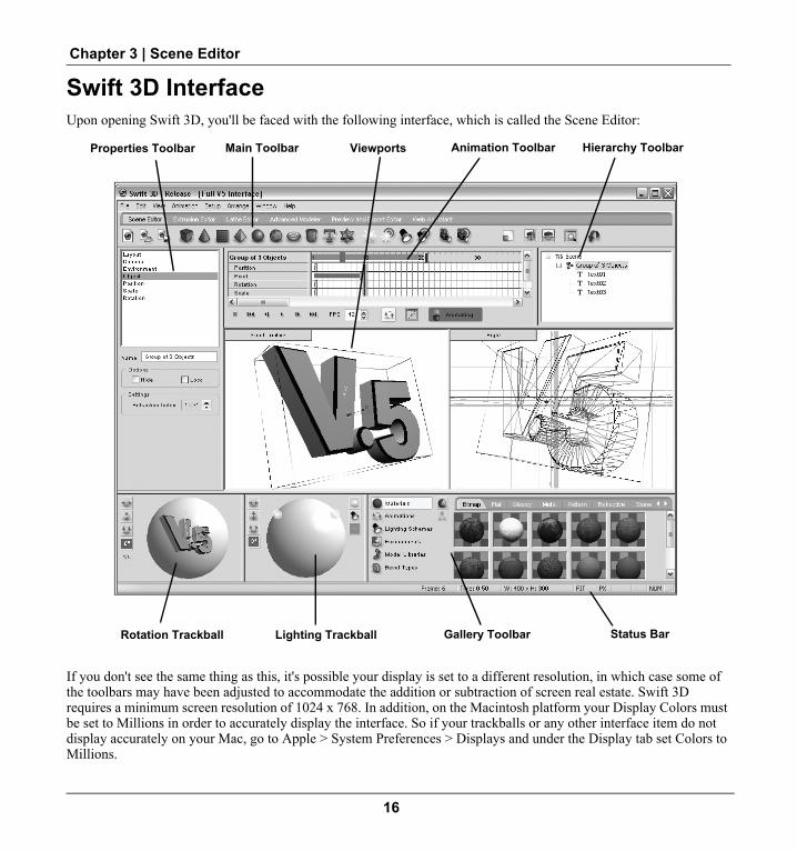
Chapter 3 | Scene Editor
Swift 3D InterfaceUpon opening Swift 3D, you'll be faced with the following interface, which is called the Scene Editor:
If you don't see the same thing as this, it's possible your display is set to a different resolution, in which case some of the toolbars may have been adjusted to accommodate the addition or subtraction of screen real estate. Swift 3D requires a minimum screen resolution of 1024 x 768. In addition, on the Macintosh platform your Display Colors must be set to Millions in order to accurately display the interface. So if your trackballs or any other interface item do not display accurately on your Mac, go to Apple > System Preferences > Displays and under the Display tab set Colors to Millions.
Properties Toolbar Main Toolbar Viewports Animation Toolbar
Rotation Trackball Status BarLighting Trackball Gallery Toolbar
Hierarchy Toolbar
16

Swift 3D V5 User Guide
Customizing the Swift 3D InterfaceInterface ResizeIf you prefer to work with a different size interface other than the default full screen, this preference is saved upon exit. So go ahead and tweak Swift 3D so it comfortably fits into your desktop, close it up, open it again, and yes, it will be in the same place with the same size. And if you are running dual monitors this is supported as well, so spread yourself out across all of that nice real estate.
ToolbarsSwift 3D ships with a standard configuration of all toolbars docked on Windows and all toolbars floating on Macin-tosh. Toolbars cannot be docked on the Mac, but you can arrange them in any way you find suitable to your workflow. On Windows, y ou can customize the interface by undocking and docking almost all of the toolbars (the various win-dows you see) to meet whatever layout needs you might have. The only toolbar you cannot undock is the Main Toolbar that stretches across the top of the interface, as well as the Viewports. Depending on the size and shape of your 3D scene you can undock some toolbars and leave them floating in convenient places.
To undock a toolbar:1. Move your cursor near any border of the toolbar you wish to move until it changes into a Docking Cur-
sor.2. Click and hold the mouse button and a black border will appear around the toolbar indicating that you
have it in your control.3. Move the toolbar to your desired location. As you approach the edges of your screen the toolbar may resize itself
to fit into a new docking position. If you would like to leave the toolbar floating, hold the CTRL key down while you move it.
4. When you've got the black border where you want it, release the mouse button and you're in business.
Hide/Show Undocked ToolbarsTo hide a visible toolbar or show a hidden toolbar, use the View menu. Visible toolbars will be checked and hidden toolbars will be unchecked. The menus are covered more in-depth in Appendix A at the end of the User Guide.
Another way to manipulate the interface's appearance is to move the borders between the toolbars, thus resizing them without changing their location. For instance, maybe you would like to see more materials displayed so you resize the two trackballs to allow more room for the Gallery Toolbar.
To resize toolbars:1. Move your cursor near the edge of the toolbar you wish to adjust. When the cursor changes to the Move
Border Cursor, click-and-drag on the border.2. Adjust the toolbar's border to your desired position.3. Release the mouse button. Voila!
NOTE: If you've tried to make the toolbar smaller than it's comfortable with (they're sensitive about looking too diminutive) it will bounce back to its smallest possible size.
17

Chapter 3 | Scene Editor
Nick's TipsWe spent many an hour discussing the most efficient layout for Swift 3D, and this default configuration was
the chosen one. But I have never advocated the quashing of innovation, so by all means commence the undocking pro-cedure, captain. But I have to warn you ahead of time that once you begin moving these things around, all hell could break loose. Not a literal hell mind you, with fire, brimstone and out-of-order soda machines, but rather a situation where you may not know exactly how to get back to where you originally started. The best order for re-docking the toolbars is this:
1. The Properties Toolbar goes to the left.2. The Animation Toolbar goes to the top.3. The Trackball Toolbar goes to the bottom.4. The Lighting Toolbar goes to the bottom (just to the right of Trackball Toolbar).5. The Gallery Toolbar goes to the bottom right.
User PreferencesIn addition to customizing the interface you can also change the default settings for a variety of the more commonly used functions in Swift 3D. To access the User Preferences dialog, from the Main Menu go to Setup > User Preferences (Win) or Swift 3D > Preferences (Mac). The User Preferences dialog will appear, allowing you to change certain Layout, Animation, Extrusion/Text, Performance and Export set-tings.
To make changes simply enter new values and click OK. The changes will take effect once you open a new document or close down and reopen Swift 3D.
Editor TabsYou'll notice that there are six tabs along the top of the Swift 3D interface, with the default being the Scene Editor since this is the primary working area within Swift 3D. While these other editors will be covered in great detail in upcoming chapters, a quick overview of each editor’s purpose will start you off with a strong idea of
18

Swift 3D V5 User Guide
Swift 3D’s workflow and therefore provide beginners with a better understanding of the Scene Editor features that will be highlighted in the rest of this chapter.
Extrusion EditorWelcome to a bizarre world where everything you draw in 2D instantly becomes 3D. It's called the Extrusion Editor and it's cool (but I'll let you be the judge of that). The basic idea is that you pick up a pen, draw some stuff within this inter-face and it will instantly become a 3D object in the Scene Editor. This powerful tool lets you cre-ate 2D extrusions from within Swift 3D, elimi-nating the need for another 2D drawing application. The Extrusion Editor also includes an Animation Timeline that allows you to ani-mate the paths of your extrusions over time, allowing for full-fledged morphing of extruded objects. For more information on this topic, refer to Chapter 9: Extrusion Editor on page 89.
19

Chapter 3 | Scene Editor
Lathe EditorOnce again we venture to a land seldom visited by mere 2D mortals. The Lathe Edi-tor is a 3D modeling tool that allows you to draw a simple path and have Swift 3D spin that path around an axis and instantly create a 3D object in the Scene Editor. The Lathe Editor and the Extrusion Editor share a similar interface, but their functions are quite dissimilar. And once again, in our efforts to supply more creative powers to the designer we’ve included a path animation feature that allows you to create lathed shapes that change over time. For more information on this topic, refer to Chapter 10: Lathe Editor on page 103.
Advanced ModelerThis feature is less a modeling tool and more an entire modeling environment. When you've hit a point where the supplied shapes and your 2D drawing skills aren't going the full distance, the Advanced Modeler is here to take you the rest of the way to the land of total and complete modeling power and versatility. In this interface you have full editing control over the polygonal structure of your models as well as the ability to apply detailed textures to their surfaces through a UV tex-ture coordinate system. With the new Mesh Morpher in Swift 3D V5, you will also use the Advanced Modeler to create Mesh Groups and Targets with which you can animate the very vertices of a model mesh while working in the Scene Editor. For more information on this topic, refer to Chapter 13: Advanced Modeler on page 119.
Preview and Export EditorSwift 3D’s powerful vector and raster rendering engines, RAViX and the EMO Ray Tracer reside within the Preview and Export Editor. The beauty of Swift 3D is that it leaves the decision up to you as to whether you want to render to vector or raster file formats. The basic workflow of the Preview and Export Editor is a simple four-step process. First you choose whether you will be rendering out to a vector file format using our RAViX engine, or to a raster file format using our EMO Ray Tracer. You then choose the file type options, and if you are rendering to vector, you also get to choose what fill and edge style of output you want. When all of your options are set you render a preview of your scene, and finally, if you like what you see you export your ren-dered animation to a file.
Web AssistantThe Web Assistant was developed in order to make your life with Swift 3D easier by providing you direct access to the primary web resources Electric Rain makes available to its customers. The Web Assistant works by opening up your
20

Swift 3D V5 User Guide
browser directly into the Swift 3D interface (Win) or into a separate window (Mac) and taking you to a web page that will provide you with quick links to resources like software updates, registration, your customer account, announce-ments and other great community offerings.
Scene EditorMost of your time will be spent working within the Scene Editor, and that's where we'll stick for the rest of this chapter, starting smack dab in the middle of it all with the Viewports.
ViewportsThe Viewports are your windows into the 3D scene you are about to create. If you're an analogy-lover like myself, the lens of a video camera fits the bill. You should be very interested in what goes on within the confines of the Viewport since it's where the only visible action will take place in the scene. If you have objects that lie outside of the Viewport they will not be seen in the final exported file unless they enter the Viewport through an animation path or the camera happens to look in their direction.
Returning Swift users will notice the addition of a yellow border that displays within each Viewport. This represents the Layout dimensions in relation to the size of the Viewport on screen. Any object that crosses over this border will be cropped when your scene is rendered.
By default, Swift 3D will open with two Viewports showing, but you can work with anywhere from one to four open. To open an alternative layout of two or three Viewports or to return to the default configuration, go to View > View-ports and select the desired preset. You can customize the Viewports using the following arrangements: 2 Viewports, 1 Left, 1 Right, 2 Viewports, 1 Top, 1 Bottom, 3 Viewports, 1 Top, 2 Bottom, 3 Viewports, 2 Top, 1 Bottom, 3 View-ports 1 Left, 2 Right, 3 Viewports, 2 Left, 1 Right. Making all four Viewports visible at one time is accomplished by selecting Show All Viewports from the same menu. Show All Viewports can also be accessed from any of the View-port Menus. To open a single Viewport, go to that Viewport's Menu button and select Maximize.
Camera ViewsSwift 3D offers seven different cameras by default with the ability to add as many custom cameras as you like. Camera views can be selected from the Viewport Menu button located in the upper left corner of the Viewport. Information on working with cameras can be found in the chapter on Cameras. IMPORTANT: To move the cam-era’s view you must first hold down the ALT key (Win) or COMMAND key (Mac) to enter into Camera Mode. For more information on this topic, refer to Chapter 16: Cameras on page 191.
21

Chapter 3 | Scene Editor
Any camera in the Scene Editor can be switched to Orthographic view from the Viewport menu. For more details regarding Orhtographic view refer to Chapter 5: Viewport Properties.
Reference GridIn our daily 3D world it's easy to stay oriented since we have familiar reference points like walls, floors and ceilings. Within Swift 3D's world, we have supplied you with a 3D grid based on the X, Y and Z coordinate system. The red line represents the X or horizontal axis, the green line is the Y or vertical axis, and the blue line (just a point until you alter the camera view) shows you the depth of your 3D world, or your Z-axis. The intersection of these three lines is the absolute center of the scene, and its coordinates are X = 0, Y = 0 and Z = 0. There are three grid options for every Viewport: XY, YZ and ZX. Each camera view comes with a default setting, but you can choose to turn these grids on and off individually or all together through the Viewport Menu button.
Properties ToolbarThe Properties Toolbar is like backstage at a big theatre production. All the action may be occurring on the main stage, but there's much more activity happening behind the scenes that makes the production come off as spectacular. The Property List Box, located at the top of the Properties Toolbar, is basically a list of categories of properties. As these categories are selected you are presented with a Property Page that displays settings related to that particular category.
The key to gaining a quick understanding of the Properties Toolbar is to note that three properties are always displayed: Layout, Camera, and Environment. Beyond these three properties, the Properties Toolbar is completely selection sensitive. What-ever object you have selected at the time, whether it be an object, light or camera, will determine which information gets displayed within the Properties Toolbar. Each type of object can also have different characteristics that can be manipulated.
The information contained within the Properties Toolbar does not neatly fit into any one chapter, but we’ve done our best to make this information easy to find. Informa-tion on Layout and Environment can be found in the chapter on Viewport Properties and Camera properties can be found in the chapter on Cameras. As for the rest of the selection sensitive properties, the chapter on Working with Objects details the prop-erty pages that are common to most objects, and as each specific object is discussed in subsequent chapters, we will cover the property pages that are relevant to each type of object. The Advanced Modeler also has its own set of property pages that are discussed in detail throughout that chapter.
NOTE: Many of the property pages use numbers to represent the various settings you can apply to your objects. There are three main ways of adjusting these numbers:
1. Type your desired number into the field (if field is gray then this option is not available).2. Nudge the number up or down by clicking the corresponding arrow on the spin button.
22

Swift 3D V5 User Guide
3. Position the cursor between the arrows on the spin button and when you receive the double lines cursor icon you can click-and-drag up or down.
You will also find these numerical controls within other sections of the interface and you can use whichever strategy works best in your situation.
Main ToolbarThe Main Toolbar contains a variety of buttons that let you insert objects, create lights and cameras, and manipulate other parts of your scene.
File Shortcut ButtonsThese buttons allow you to quickly open a New document, Open an existing document, or Save the current project you are working on. Swift 3D project files are saved to the .t3d file format.
Create Object ButtonsThese buttons allow you to create text and sim-ple objects (called Primitives) within your scene. They are about as easy to use as a light switch—a simple click will place your chosen object onto the intersection of the X, Y and Z axis lines. All of these objects arrive in your scene with their default characteristics, including standard size and a default glossy gray material applied to them.
Create Light ButtonsThese four buttons allow you to create lights designed to be manipulated within your scene. Called Scene Lights, these lights differ from the Trackball Lights discussed in a moment.
Create Camera ButtonsHere you are able to create two specific types of cameras, the Free Camera and the Target Cam-era. These cameras are unique in that they can be manipulated directly within your scene and can be fully animated.
Convert Text to PathsThe Convert Text to Paths button takes your currently selected text and turns it into a series of paths that can be edited in the Extrusion Editor.
Frame All ObjectsThe Frame All Objects button allows you to quickly re-orient your camera view to include all of the objects in your scene.
23

Chapter 3 | Scene Editor
Scaling ModeThe Scaling button puts you into a temporary mode where any object you click-and-drag on will have its scale altered. Scaling mode is a one-time thing, so as soon as you’re done scaling one object, it will toggle off automatically.
Render Viewport ButtonsSince Swift 3D relies on the OpenGL rendering engine that comes standard with your computer to display the graphical representation of your scene within the Swift 3D Viewport, when you apply ras-ter materials to your objects you will not see them in clear detail. Because of this there is a Scanline Renderer in the Scene Editor that allows you to preview your scene and materials. Render Window will render the entire active Viewport, while Render Rectangle will turn your cursor into a marquee selection tool that you can then click-and-drag over any area of the Viewport that you would like to see rendered. To CANCEL the rendering process, click again on the Render Window button.
Undo/Redo ButtonsThe Undo and Redo buttons provide a quick way for you to undo or redo any action, regardless of which editor you were working in. Unlike previous versions of Swift 3D, a universal Undo stack (think of this as a list that holds all of your actions) is now shared between all editors, so using the Undo and Redo command will take you through the various editors as necessary.
It is important to understand that a complete copy of your scene gets placed into the Undo stack each time the scene is altered, which can definitely use up a lot of memory. Once you’ve reached a point when you are sure you no longer need access to the Undo stack you can manually clear it using the Edit > Clear Undo function.
By default the number of Undo Levels is set to unlimited, however you may specify maximum undo levels or fully disable the undo function from the User Preferences dialog. To access the User Preferences dialog, from the Main Menu go to Setup > User Preferences (Win) or Swift 3D > Preferences (Mac).
Animation ToolbarThe Animation Toolbar is used to make your scene come to life (but it won’t come to life unless you click on the Animate button). Whenever your scene changes over time, the Animation Toolbar displays the rele-vant information. It can be used as a reference when using drag-and-drop animations, or as a powerful keyframe animation tool, much like in Adobe Flash. There is an entire chapter on Animation that provides details on how to use this timeline.
24

Swift 3D V5 User Guide
Animate ButtonsThe Animate button is also a mode you slip in and out of, only this one allows you to make changes to the Animation Timeline when it is toggled on. While off, however, you cannot make any alterations to the Timeline. The only exception to this rule is when you are apply-ing drag-and-drop animations from the Animation Gallery. Turning on the Animate button also enables the Animation Path Mode button to its left, which allows you to edit the Bezier paths of your animation. Previously situated in the Main Toolbar, both of these commands are now located just below the Animation Timeline.
Rotation ToolbarDown in the lower left corner of your scene are two toolbars that are probably unlike anything you've ever used before. We call them Crystal Trackballs and they are really very easy to use. They work as if you were rotating a virtual trackball with your mouse. Just click-and-drag on the surface of the ball and it will turn whichever way you choose.
The Rotation Trackball is designed to let you adjust the orientation of objects in your scene. It remains inactive until you have selected an object. Once you have something selected, the object appears within the Rotation Trackball and can be rotated by click-ing and dragging on any part of the trackball itself. You will see the object spinning or rotating within the trackball and within your active Viewport simultaneously. If you have multiple objects or a group of objects selected, they will all appear in the trackball as well.
The buttons to the left of the Rotation Trackball are available to help refine your rotation move-ments. Note that rotation can also be numerically controlled through the Rotation page of the Properties Toolbar. Read more about using the Rotation Trackball in the Working With Objects, Lighting and Camera chapters.
Previous users of Swift 3D might be asking about now where all of the important Reset buttons that were once to the right of the Rotation Trackball have gone. Don’t panic, we haven’t done away with these critical functions. Clicking on the new button just below the Rotation Increment setting will put these handy com-mands at your disposal, allowing you to quickly restore objects to their original state.
Lighting ToolbarThe Lighting Trackball allows you to control the placement, location and type of lights that illuminate your scene. Think of the lights as being positioned on the outside of an imaginary sphere shining into the center of your scene. The sphere's size can vary depending on the size of your scene, but it is always twice as large as would be necessary to encompass your entire scene. In other words, the more spread out your objects are, the farther your lights will be from the center of your scene.
The buttons to the left of the Lighting Trackball are available to help refine your rota-tion movements, and the buttons on the right are there to create and delete Trackball Lights. A new scene comes complete with two standard lights on the Lighting Trackball, but you are free to add, delete, or use Scene Lights (covered in the chapter on Lighting) to illuminate your scene as you see fit.
25

Chapter 3 | Scene Editor
GalleryToolbarThe Gallery Toolbar is a combination of six galleries: Materials, Animations, Lighting Schemes, Environments, Model Libraries and Bevel Types. All of the galleries work under the basic princi-pal of drag-and-drop and everything you see within the galleries when you launch Swift 3D for the first time are what comes standard with Swift 3D. All galleries are designed to be augmented and cus-tomized by the user, so please don't infer that what you see is what you get. It's merely what you start with.
The buttons on the left of the toolbar allow you to select which gallery is displayed at any given time. The Gallery Toolbar is present in the Scene Editor and Advanced Modeler. However, only the Materials and Model Libraries are enabled for use in the Advanced Modeler, which is why all of the other gallery buttons are grayed out.
Gallery ManagementEach gallery contains categories, represented by the tabs located across the top of the gallery, which provide a conve-nient way to keep the gallery contents organized. The scrollbar located on the right side of the gallery allows you to scroll through the content within each tab. Galleries can be customized by adding new categories (tabs), editing exist-ing content or adding your own creations. This section of the User Guide will only cover the basics of how the Galler-ies are managed and organized, so for specific information on how to actually apply, create or edit different types of gallery content please read the gallery sections in the chapters covering those topics.
Gallery SetupThe Setup menu on the main menu is your doorway to the organizational structure of the Gallery Toolbar. When you drop down the Setup menu you have the choice of accessing the setup for each of the individual galleries. The Gallery Setup dialog will appear with tabs across the top for each of the galleries. For your convenience, the tab of the specific gallery you chose from the Setup menu will be selected. Once the dialog is open, you can jump to any of the galleries by clicking on the tabs along the top. The Gallery Setup dialog can also be accessed by right clicking (Win) or CTRL + clicking (Mac) on the palette window (frame) surrounding the thumbnails, not the thumbnail itself. (Note: The Bevel Gallery is not accessible from the Gallery Setup dialog because you cannot edit or add content to this gallery.)
Category List BoxAlong the left side of the Gallery Setup is a Category list box that displays the names of all the tabs located along the top of each gallery in the Gallery Toolbar. The categories within each gallery are simply suggested organizational schemes to get you started. For example, even though we have started you out with materials nicely organized by type, there is nothing preventing you from saving a transparent material into the reflective category. As you will see in a bit, these categories are just like the directories on your harddrive.
26

Swift 3D V5 User Guide
Content List BoxThe Content List Box resides underneath the Category List Box and contains the names of all the individual materials, animations, lighting schemes, etc. that reside under each category tab. For example, if you have the Material tab selected and choose Glossy Colors from its Cat-egory list box, all of the colors that reside within the Glossy category, and thus under the Glossy tab of the Material gallery, are displayed.
Naming Conventions
All default content that is shipped with the program begins with an “ER”as a reminder that these are the items that came with the pro-gram. You can certainly alter these items in any way that you want, but keep in mind that if you ever need the original content you will have to uninstall and reinstall the program to get it back. Additional naming conventions have been set up for the Materials and Models in order to help lessen the confusion regarding the different content items that reside within each gallery, but again these conventions are just for your convenience. Since the Model gallery can contain meshes, extrusions or lathes, the default models that come with that gallery are prefaced with ER Mesh, ER Extrusion or ER Lathe. The Material gallery contains both vector and raster materials, which are identified with the preface ER Raster or ER Vec-tor.
Gallery Setup ButtonsAlong the right side of the Gallery Setup dialog is a series of buttons that vary depending on which gallery is active. The tabs common to each gallery are as follows:
New Category allows you to add a new tab to the gallery. Simply click on this button and enter your desired category name. Note that the new tab will not appear until you exit the Gallery Setup dialog.
Edit allows you to edit the selected item. The degree to which you can edit depends upon what gallery tab you are in. For example, clicking on Edit under the Material tab will bring up the Material Editor, which provides you complete access to all of that material’s base properties. Clicking on Edit under the Animation, Lighting, and Model tabs will only give you access to editing the name and a few other basic properties since the content of these galleries can only be edited directly in the workspace where they were created.
Remove permanently deletes the item that is currently highlighted in the content list, which is why it will kick out a warning message asking you to continue or abort. Note: You cannot remove entire categories using the Gallery Setup, only individual items within the categories. If you need to remove a category, this can only be done by deleting that folder directly from your file structure. Read more information about this in the upcoming section on Gallery Location and File Formats.
Copy will copy the item that you have selected in the content list. The copy will appear at the bottom of the list and will be given the default name of the original item with a [1] appended after that name. You can change the name by then selecting the Edit button.
27

Chapter 3 | Scene Editor
Move allows you to move an individual item (material, animation, model, etc.) from one category to another. When you click on this button, a new dialog appears that lists all existing categories. Simply click on the category to which you want to move your selected item, then click OK.
The Preview Window simply displays what the current selection looks like.
Since you can Add or Edit Materials and Environments directly from the Gallery Setup, under these tabs you will also see the following buttons:
Add Material or Add Environment lets you add new materials to existing categories. The category that is currently highlighted in the Category list is where this new material or environment will be added. When this button is selected it brings up the Material or Environment Editors. The Material Editors can also be brought up by double clicking direc-tion on the material or environment preview thumbnail in the galleries. For more information on this topic, refer to Chapter 14: Materials on page 167.
Saving New Content to the GalleriesThere are slightly different steps to saving new content to each of the galleries since there are obviously vast differences in the under-lying architecture that makes up an animation versus a model. As a basic overview, new materials and environments are created and saved through the Material or Environment Editors, while anima-tions, lights and models are saved by clicking on the Viewport background or object and choosing File > Save Animation, File > Save Lighting or File > Save Model. These steps are detailed in the upcoming chapters on Animation, Environment, Lights, and Mate-rials. Since the Model Gallery contains Mesh, Extrusion and Lathe objects, steps for saving these various types of models are detailed in the Extrusion Editor, Lathe Editor and Advanced Modeler chap-ters.
Gallery Location and File formatsAll pre-made gallery content, with the exception of the Bevel Gal-lery, is saved in a proprietary file format and is stored in directories where Swift 3D is installed on your machine. The directories are as follows:
(On Windows the complete file path is C:\Program Files\Electric Rain\Swift 3D\Version 5.00 and on the Mac it is Applications\Swift 3D\Version 5.00)
...\Swift 3D\Version 5.00\Animations\Animation Name.t3a
...\Swift 3D\Version 5.00\Environments\Environment Name.t3e
...\Swift 3D\Version 5.00\Lighting\Lighting Name.t3l
...\Swift 3D\Version 5.00\Materials\Material Name.t3m
...\Swift 3D\Version 5.00\Models\Model Name.t3om
Under each directory are folders that correspond to the category tabs that reside across the top of each gallery. Any new content added by you will get saved to the folder that corresponds to the tab in the Gallery under which the item was
28

Swift 3D V5 User Guide
saved to. If you create a new category, a new folder will be created with that category's name. If you need to delete a category, you can only do this by deleting or moving the actual category folder. This is a permanent procedure so make sure you are confident in what you are doing. Reinstalling Swift 3D will always restore any default categories that come with the program, but if you are deleting your own stuff you will not have any recourse for retrieving those files.
Sharing Gallery Content With Other UsersThe great thing about the galleries is that they make it easy to share your creations with other users. There are two ways to go about sharing files:
1. Navigate to the Swift 3D\Version 5.00 directory on your harddrive, open the folder that corresponds with the gal-lery content you wish to share, and copy the actual .t3X file (e.g., animation.t3a) and give that file to your fellow Swift 3D user. The recipient of the file will simply need to copy it into the corresponding directory on their hard-drive, choosing any category to place it under, and the next time they run Swift 3D that item will be available for use from the gallery.
2. Copy and send the user your full .t3d file. When the recipient opens the .t3d file in Swift 3D, they can save the desired animation, environment, lighting scheme, material or model directly into the corresponding gallery.
Now Go Forth and Make Me Proud!So that’s the quick tour of the Scene Editor. From here you can start skipping around to the sections you find most interesting, or perform my favorite option, which is to read the whole darn book cover to cover. That way you’ll know everything I know about Swift 3D within a few short hours.
29

Chapter 3 | Scene Editor
30

Chapter 4 Tutorial
OverviewAlthough reading about Swift 3D can be an educational experience, there’s no sub-stitute for hands-on, get your feet wet, grab the controls experience. If you’re the type of person who enjoys a good trial by fire then this chapter is going to suit you just fine. Those of you return users might be asking where the famous lamp tutorial went that has helped so many users cut their teeth on 3D modeling. Well, times change and as Swift 3D has evolved, we felt the need to move on to something that gives a little more taste of what Swift 3D is capable of these days. As I’m the sentimental type, we’re going to keep it in the realm of desktop lighting, trading in the trusty desk lamp for a great piece of retro kitsch...a rocket-shaped lava lamp! If all goes well, we should end up with something that looks like the model to the right, with a little path animation to go along with it. So let’s jump in and get it done.
Open a new document and adjust the Layout and Environment1. Open Swift 3D and a new, empty scene will automatically be created for you.2. In the Properties Toolbar set the scene Height, under Layout, to 500.3. Click on Environment in the Properties Toolbar.4. Double click on the Background Color selection box.5. Choose a color you like (I went with black for contrast).6. Click OK.
NOTE: I’ll be using a white background in the screenshots at times for easier view-ing.
31

Chapter 4 | Tutorial
Create the globe and cone in the Lathe EditorIf you skipped over the previous chapter, the Lathe Editor is a 3D modeling tool that allows you to draw a simple path and have Swift 3D spin that path around the Y axis, instantly creating a 3D object in the Scene Editor.
1. Click the Lathe Editor tab along the top of the main interface.
2. Using the Add Point Tool draw the rough shape of the rocket’s body and cone like the one pictured to the right. It will be a little messy when you first lay down the points but we'll clean it up shortly.
3. Using the Shape tool select the appropriate Corner Points and change them to Curve Points in the Points Properties dialog box. This will allow you to adjust all of your Bezier curves to create a nice curved shape like the one pictured to the right. Make sure that the top point of the cone and right most points at the base of the globe rest on the center line (x=0). To double-check you can select them and set their position numerically through the Points Properties dialog box.
4. Once you are satisfied with the lines you have made, simply go back to the Scene Editor by clicking on the tab at the top left of the main interface, and Swift 3D will have your freshly lathed object waiting for you.
32

Swift 3D V5 User Guide
5. Back in the Scene Editor you should see something similar to the right when viewing the Front Viewport. It looks more like a silver bullet than a lamp, but that will change shortly. Make sure the object is selected and under Lathe in the Properties Toolbar set Radial Segments to 32. NOTE: If the lathe object is taking up the entire Viewport you will want to adjust the camera to make working more manageable. To Zoom the camera hold down the ALT key (Win) or COMMAND key (Mac) and right click-and-drag (Win) or CTRL+ click-and-drag (Mac) anywhere in the Viewport. Drag the cursor upward to zoom in and downward to zoom out. To Pan the camera hold down the ALT key (Win) or COMMAND key (Mac) and drag anywhere in the viewport.
Create the lamp base with a cone primitive1. In the Scene Editor, click the Create Cone primitive button and drag the new
object below the beginnings of our lamp.
2. With the Cone category selected in the Properties Toolbar, adjust the properties as follows: Sizing Top Radius: 0.280 Bottom Radius: 0.590 Length: 1.600 Segmentation Axial: 16 Radial: 30
3. Toggle the Lock Vertical button on within the Rotation Toolbar, set the Increment to 90º and flip the cone 180º.
33

Chapter 4 | Tutorial
4. Position the cone so it fits the bottom of the globe as seamlessly as possible. Adjust the Bottom Radius or Scale the entire cone to get a better fit if needed.
Create the tail fins/legs with the Extrusion Editor1. Click the Extrusion Editor tab along the top of the main interface.
2. Click the Tanget Point button.
3. Draw a shape similar to the example on the right using four control points, adjust-ing the Bezier curves in order to obtain a smooth swept back fin.
4. To create the holes in the fin, add a circle by clicking the Create Circle Path but-ton. Select the circle by double clicking the path and scale it down to fit within the upper left side of the fin. (Hold down the CTRL key to achieve uniform scaling.)
5. Select the path and copy-and-paste, positioning the new circle to the lower right of the first and reducing the scale slightly. Repeat a third time and you should end up with something similar to the image on the right.
6. When satisfied, return to the Scene Editor. When you do Swift 3D will have already made your new object with holes for you.
7. With the fin still selected click on Sizing in the Properties Toolbar and set the Depth to 0.010.
34

Swift 3D V5 User Guide
8. Select Bevels in the Properties Toolbar and set the bevel style to Outer Round and the Depth to 0.050.
9. Click-and-drag on the fin to position it on the right side of the lamp’s base, as pic-tured to the right.
10. To make rotating the fin easier, we will set it’s Pivot Point to the central axis fot he rocket body. With the fin selected, under Position in the Properties Toolbar, click the Move Pivot Only button and set the X and Z coordinates to 0.
11. Copy-and-paste the fin and switch to the Top camera view, keeping the newly pasted fin selected. This is where we will create 3 fins of equidistant positions.
12. To make positioning the fins easier, select Orthographic view at the bottom of the Top Viewport menu. NOTE: Refer to the next chapter on Viewport Properties to learn more about the benefits of using Orthographic views.
13. Toggle the Lock Spin button on within the Rotation Toolbar, set the Increment to 60º, and spin the fin 120º.
35

Chapter 4 | Tutorial
14. Copy-and-paste the currently selected fin and repeat step 13 so that you now have three fins spaced evenly around the lamp’s base.
Create a surface for the lamp to rest on1. Click the Create Plane primitive button in the main toolbar.
2. Select the plane in the Top Viewport.3. Toggle the Scaling Mode button by clicking it in the main toolbar.
4. Click-and-drag from the center of the plane towards the edge to scale it up so that it takes up the entire Top Viewport.
5. From the Top Camera view, SHIFT + right click-and-drag (Win) or Option + click-and-drag (Mac) down towards the bottom of the Viewport to move the plane away from the camera, and thus lower in the Front Camera’s view.
6. Go back to the Front Camera view to fine tune the plane’s position. You may need to zoom the Front Camera away from the scene by ALT + right clicking-and-dragging (Win) or COMMAND + CTRL + clicking-and-dragging (Mac) on the background, or by clicking the Frame All Objects button.
36

Swift 3D V5 User Guide
Getting organized using the Hierachy ToolbarBefore going any further, let’s take a moment to organize our scene by using the Hierarchy Tools.
1. Select each element of the scene individually and give them unique identifiers. This can be done in the Name section of the Object category of the Properties Toolbar or by double clicking an object’s name in the Hierarchy Toolbar in the upper right corner of the Scene Editor. I am using the names Body, Base, Fin 1, Fin 2, Fin 3 and Ground.
2. Once all items have names, it’s time to organize them in the Hierarchy Toolbar. In the hierarchy, drag-and-drop each of the fins beneath the Base, which creates a hierarchal relationship between them, with the fins becoming children items of the lamp base. Your Hierarchy Toolbar should now look similar to that on the right.
Apply materials in the Scene Editor1. Click on the Metal materials tab in the Material Gallery.2. Click-and-drag the Chrome material to the lamp’s base.
3. Toggle the Material Drop Surface button to the All Surfaces mode (blue highlight) so you can drop a material onto the faces, edges and bevels of the fins all at once.
4. Click-and-drag the Chrome material to each of the fins.
5. Click-and-drag the reflective material of your choice to the ground plane. I am using Reflective Black, the last material in the Reflective category.
In order to apply different materials to the cone and globe portion of the lamp we need to go into the Advanced Editor and create Surface Groups to differentiate between the areas.
37

Chapter 4 | Tutorial
Applying materials in the Advanced Modeler1. Select the lathed rocket body and click the Advanced Modeler tab in the main
toolbar.
2. Toggle the Edit Mesh button in the top toolbar to active and click “Yes” when the mesh conversion warning window pops up.
3. Click on the Face Selection button located in the main toolbar.
4. Working in the Left Viewport, click-and-drag a selection bounding box around the cone of the rocket to select its faces.
5. Click on the Surface Groups category in the Properties Toolbar and click Group Selection. Name the new surface group “Cone” and rename the default “All Surfaces” to Body.
6. In the Material Gallery, click on the Metal category and drag-and-drop the Chrome material to the cone.
7. From the Transparent category, click-and-drag Transparent 51 to the body in the same way.
8. Return to the Scene Editor and click the Render Preview button in the main tool-bar to see how things are looking.
Now that our rocket is finally looking more like a lamp, it is time to create the most important part of any lava lamp...the “lava”!
38

Swift 3D V5 User Guide
Create and animate the “lava” with the Lathe Editor and Sphere primitives1. In order to get the globe out of our way, select the Body and activate Hide
in the Object category of the Properties Toolbar.
2. Set the left Viewport to the Front Camera view and the right Viewport to Top.
3. In the Front Viewport’s option menu, activate Show > Hidden Objects. This will let you use it as a reference while positioning our blobs of lava, without worrying about accidentally moving the globe.
4. Click on the Lathe Editor tab.
5. Draw a shape similar to the one on the right.
6. Toggle on the Animate button and click on frame 40 in the timeline.
7. Edit the path so it looks similar to that on the right. The position of the two bottom points should not change. To preview the animation, click the Play button in the Animation Timeline and make adjustments as necessary.
39

Chapter 4 | Tutorial
8. Return to the Scene Editor and position the shape so that it rests on top of the base of the lamp. Scale the Lathe object in the Scene Editor or modify the path in the Lathe Editor as needed to make it fit to the base.
9. Once in position, apply any Flat material you wish. I’m using a bright green (Flat 23 to be exact).
10. Add additional blobs of lava as you like using Sphere primitives, adjusting the Scale and Shear values under the Scale category in order to achieve variations in size and shape. Make sure to switch between camera views when position-ing them in order to make sure all are placed within the lamp's globe. While I won’t dictate the rest of this step, reference the image to the right to see my approach. NOTE: If you wish to animate additional lava, the Scale and Shear properties mentioned above can be animated, along with motion.
While our model is shaping up nicely, the second half of the tutorial will focus on other elements of a scene, setting up a custom camera, lighting, simple animation and finally rendering. Before moving one, however, I want to give an additional shout out to the online Tutorials, which are accessible through the Web Assistant. Why now you ask? In the remaining images of this tutorial you will notice that I have added a power cable to my lamp. The technique for creat-ing a cable like this, and many other modeling techniques, can be found in the online tutorials and I highly suggest you check it out (after reading the manual!). I know, it’s like giving a kid a bag of candy but saying they can’t eat it until AFTER they finish their dinner.
NOTE: The specific tutorial for creating a power cable, and other similar structures, is accessible at http://www.erain.com/support/Tutorials/v4/TubesWires/ or via the Web Assistant at Tutorials > Swift 3D v4 & v4.5 > Tubes & Wires - Advanced Modeler Tut.
Setting up the Camera1. Working in the Top Viewport of the Scene Editor, click on the Create
Target Camera button in the main toolbar to add a new camera to the scene.
40

Swift 3D V5 User Guide
2. Select the camera in the Hierarchy Toolbar. It should be the only camera present in the Hierarchy and will have a default name of “Target Camera01.”
3. Click on the Camera Position properties in the Properties Toolbar and set the Camera and Target positions as follows: Camera Position X: 10.50 Y: 6.65 Z: 5.60 Target Position X: 0.00 Y: 1.00 Z: 0.00
4. Assign the new camera to the current Viewport by selecting it from the Viewport Menu.
41

Chapter 4 | Tutorial
Add custom lighting to enhance the scene1. Working in the Front Viewport, select the default light on the right side of the
Lighting Trackball and delete it by clicking the Remove Trackball Light button to its right or by simply hitting the Delete key on your keyboard.
2. Select the remaining Trackball Light and uncheck Shadows and Specular in the Point Light properties.
3. Click the Create Target Spot Light button in the top toolbar and select the light within the Viewport or through the Hierarchy (Spot Light01).
4. In the Spot Light properties, double click the Color and change it to a light gray. This will reduce the brightness of the light.
5. While still in the Spot Light properties, set the Spot Light Options as follows: Fade: 35.00 Cutoff: 25.00 Tightness: 1.00
42

Swift 3D V5 User Guide
6. With the properties set, it’s now time to position the light. Set the Light Posi-tion properties as follows: Light Position X: 11.70 Y: 8.60 Z: -3.00 Target Position X: 0.00 Y: 1.00 Z: 0.00
7. Add an additional Target Spot Light to the scene. This light will act to better illuminate the lava from below. Set the Spot Light and Light Position proper-ties as follows: The light color should match the lava color and turn off Shadows and Specu-lar. Fade: 35.00 Cutoff: 38.00 Tightness: 1.00 Light Position X: 0.00 Y: 0.55 Z: -0.00 Target Position X: 0.00 Y: 4.00 Z: 0.00
43

Chapter 4 | Tutorial
Perform a render previewTo get a better idea what our scene really looks like now that we have mate-rials and lighting in place, we will perform a render preview within the Scene Editor.
1. Set the Left Viewport to use the Target Camera.2. Click the Render Window button in the main toolbar.
The first thing I notice in my render is that the reflective materials look rather flat, as they do not have a lot of surrounding objects to reflect. Also, the reflec-tivity of the ground plane is a little strong for my taste and it appears almost totally uniform. These items are easily fixed by adjusting a few simple settings.
Adjust the properties of the plane’s material1. Select the plane object and select Material from the Properties Toolbar.2. Double click on the Material Preview window.3. Double click on the Reflection Color selection box.4. Choose a darker gray color and click OK. This will reduce the reflec-
tivity of the material.5. Reduce the Highlight Strength to 0.55 and increase the Highlight Size
to 0.70.6. Click the Generate Preview button and if you like what you see, click
OK.
44

Swift 3D V5 User Guide
Edit the Environment1. Select Environment from the Properties Toolbar.2. Double click the Environment Preview window.3. Select Procedural Smooth Random from the Pattern menu.4. Select Scale and Noise, leaving the sliders at their default settings.5. Double click in the Color Selection box and select black. Slide the color
tab to the far left.6. Double click in the Color Selection box again, this time selecting white.
Place this color near the center of the color box.7. Clicking the Generate Preview button should result in something similar
to the sample in the image.
Performing an additional test render shows pretty drastic changes. The surface of the chrome objects are much more realistic, while the plane has a great deal of variety in the surface, making for a more interesting visual. This is one of the reasons I greatly encourage performing test renders throughout a project, as a few simple changes can make a great deal of difference.
45

Chapter 4 | Tutorial
Render your scene to vectors using RAViX Although this scene was designed to ultimately be rendered to bitmap, doing so in RAViX will give you a good idea of what does and does not render well with RAViX.
1. Click the Preview and Export Editor tab along the top of the main interface.2. Under the General category of Output Options, select Flash Player (SWF) from
the Target File Type dropdown.3. With Vector selected (since we’re rendering with RAViX first) click the Fills
Options under Output Options.4. Select Area Gradient Shading from the Fill Type dropdown list.5. Turn on Include Specular Highlights, Include Reflections and Include Shadows.
6. Under the Render Preview section, click Generate All Frames.
7. When the rendering process is done you can preview your animation by clicking the Play Animation button within the Playback Controls.
8. Click Export All Frames from the Export To File section.
9. Name your file, choose a location to save it to, and click Save.
46

Swift 3D V5 User Guide
Render your scene to a raster image using EMO1. Click the Raster button at the top of the Output Options section.
2. Within the Render Preview section, select the last frame within the Animation Reel. NOTE: You can also render your animation with EMO by using the Generate All Frames option. We will just render a single frame for the sake of time.
3. Under the Render Preview section click Generate Selected Frames.
4. Click Export Selected Frames.5. Name your file, choose a location to save it to, and click Save.
You’re done!Now that you've been through this tutorial, you should have a pretty firm grasp of the Swift 3D basics. At this point you could just toss this User Guide by the wayside and start hammering away on your next 3D project, but I caution you. Aside from hurting the feelings of an unnamed documentation writer, by not sticking with your educational regime you may be causing yourself great harm in the long run. If it's inner vector peace and total Swift 3D consciousness you're after, you might just find it in the following pages of this User Guide.
47

Chapter 4 | Tutorial
48

Chapter 5 Viewport Properties
OverviewViewport Properties encompass settings found on the Layout and Environment property pages and in the Viewport menu. Consider these settings to be like the interior design settings for your 3D world. Just as if you were designing your very own living room, you'd be advised to pay attention to some of these details to ensure that you design a com-fortable 3D space for yourself. You can adjust things like the size of your room (stick with me here, we're in full-bore analogy mode), the appearance of the furniture, the color of the walls, the background lighting, and even how fast you move around. These things are important, because as you begin to fill this room with your 3D artwork, it will all be affected in some way by the properties of the room itself. So break out your Feng Shui manual and let's go to work.
Layout Properties
LayoutLayout is where you designate the size and proportions of your final rendered file. The width and height settings are represented in the Viewport by the yellow Layout Bounding Box. Within the vector world of RAViX, the dimensions of your scene can have a slight effect on the accuracy of your rendered file. You will probably only notice a slight dissipation of line and fill precision when you create a scene that is very, very small and then increase its dimensions significantly after rendering. Another factor you may want to pay attention to is the fact that the smaller the dimen-sions of your scene, the faster the Swift 3D rendering engine will crank out your final file. Both of these subtleties are fairly... well, subtle, so don’t go freaking out with the layout settings unless you’re really bored.
Now if you’re planning on outputting your scene as a raster image or animation you’ll be advised to care deeply about the Layout settings. As you know, raster images don’t take too kindly to scaling, so it would behoove you to think ahead about where your 3D rendering will be finally displayed.
49

Chapter 5 | Viewport Properties
Layout Bounding BoxUnlike previous versions of Swift 3D, version 5.0 will no longer resize the Viewports by default to proportionately fit the Layout size selected. Instead a yellow bounding box will be placed within the Viewports that represents the active stage size. Any objects outside of this border will not be vis-ible after rendering and objects crossing the border will be cropped. While working on your scene, be aware that the Render Preview features pays no attention to the bounding box and will instead render the entire Viewport.
NOTE: The default Layout dimensions can be adjusted by going to Setup > User Preferences.
Nick's TipsIf you are working with a large layout size and want to see what the actual size will look like, go to View >
Zoom View Port and change the selection from Fit to Window to Actual Size (100%). If you are using a layout size larger than what is available in the Viewports, you may want to maximize one Viewport (Viewport menu > Max-imize), otherwise you will get scroll bars since there will not be enough real estate for Swift 3D to show the actual size. If you still need more space, you can start turning off the various toolbars under the View menu, or if you consistently work with larger Viewports you may want to consider floating your toolbars. (For information on undocking toolbars, refer to “Toolbars” in Chapter 3: Scene Editor.)
OptionsRedraw All Viewports - Checking this box will cause all open viewports to redraw in real-time, so if you
move an object in one viewport, you will see it move at the same time in all others.
SettingsNudge Increment - The Keyboard Nudge controls how far your selected object will move when you nudge it with your keyboard arrow keys. The default increment of a new document is set to .10 units, however this can be designated in the User Preference dialog. Since each grid represents one unit, using the default setting of .10, it will take ten nudges to move an object from one grid line to the next. Holding down the SHIFT key while nudging with the arrow keys will move an object ten times the set nudge increment.
Trace Depth - This setting controls how deep the EMO Ray Tracer will trace for reflections and refraction (through glass). It is similar to the RAViX “Reflection Depth” control except that it applies to refraction as well.
Layout Bounding Box
50

Swift 3D V5 User Guide
Display ModesFrom the Viewport menu button you can access settings that determine what things are going to be shown within the Viewport and how they will be drawn.
Viewport Display SettingsSwift 3D relies on the OpenGL rendering engine that comes standard with your computer to display the graphical rep-resentation of your scene within the Viewport. Do not assume that what you see in the Viewport is what you will see in your final rendered scene. Textures and bitmaps can only be accurately rendered to a bitmap file format using the EMO ray tracer rending engine.
Texture Smooth Shaded - This is the default display option. When this display option is selected, objects are shown as smooth, solid shaded objects covered with their designated materials. If tex-tures or bitmap images are applied to an object, this display option also presents the best representa-tion that OpenGL can provide. Displaying textures will definitely slow down Viewport rendering speed, so if you are working with a complex scene switch to a different display option to enhance performance.
Smooth Shaded - The major difference between Smooth Shaded and Texture Smooth Shaded is that Smooth Shaded will not display textures or bitmap images to any degree of accuracy. To view textures or bitmap materials, change to Texture Smooth Shaded or use the Render Window button on the main toolbar to activate the Scene Editor’s scanline renderer. Keep in mind that whether you have a solid material, texture or bitmap applied to an object, the way the Viewport looks in Smooth Shaded mode is what you will see when you render with RAViX to Mesh Gradient Shading only.
Flat Shaded - This mode of display rendering will show your objects as shaded, but without the smooth gradients. Instead you will see all of the polygons that make up your objects, each with a separate flat fill. This setting helps to increase Viewport rendering speed when you're working with more detailed models.
Wireframe - This displays objects as wireframes only, with no shading. In other words, you will see the polygonal structure of your objects rather than their smoothed surfaces. This mode can be useful when you have complex 3D models and intricate animation paths since it speeds up the pro-cess of redrawing your objects every time you make a change in your scene.
Draw Backfaces - By default, Draw Backfaces is enabled in all of the Viewports. What this means is that the display is showing the "backfaces" or the mesh of the object that is facing away from the camera. By turning off the display of back facing polygons you can help speed up Viewport render-ing. In the Advanced Modeler, turning off draw backfaces can also help facilitate the selection pro-cess since the front facing polygons will become easier to identify.
Texture
Smooth Shaded
Flat Shaded
Wireframe
Backfaces Off
51

Chapter 5 | Viewport Properties
Reference GridReference Grid - This turns the X, Y, Z coordinate reference grids on and off. All of the numerical coordinates will still exist when the grid is turned off, but you won't have all of the refer-ence lines showing within the Viewport. To turn all of the grids off at once, toggle off the Show Reference Grids option.
Show OptionsAnimation Paths - Any animation paths that have been applied to an objects will display as a purple line. These paths can also be edited by clicking on the Animation Path Mode button on the main toolbar. Read more about editing animation paths in the Path Animation section of the Animation chapter.
Hidden Objects - This is used to show or hide objects that have been designated as Hidden (this is done from the Object page of the Properties Toolbar). The Show Hidden option is off by default. When this setting is enabled, hidden objects display with a stippled red effect (and can only be selected through the Hierarchy Toolbar).
Object Bones - Object Bones show the connection between objects’ pivot points based on parent/child relationships established through the Hierar-chy toolbar. A parent is always connected to all of its children. These “bones” simply serve as a visual representation of the hierarchy.
Pivot Points - This option allows you to turn off the display of all object pivot points in the Viewport.
Hidden-Locked Object Stipple - When this option is enabled, Hidden objects are displayed with a red stipple effect and locked objects are dis-played with a blue stippled effect. Note that you must also have Show > Hidden Objects checked in order to see the hidden objects to begin with. (See “Object Property Page” on page 57 for more information on this topic.)
Orthographic ViewAny Viewport in the Scene Editor can be switched to Orthographic view from the Viewport menu. When active, the Viewport menu button will turn green to act as an easy indicator that Orthographic view is in use. Using the 2D Orthographic viewing option provides many advan-tages when it comes to working in 3D space. These are a few reasons why:
1. In an orthographic view, all objects are shown straight on and maintain their right angles and parallel lines, thus reducing the chance that you will move, rotate, scale, etc. your selection in an unintended direction. You can think of this as sort of an "alignment safety zone."
52

Swift 3D V5 User Guide
2. All objects, regardless of the distance between them along the Z axis (actually, the rel-ative Z axis for each Viewport), will appear at their actual size. This is important because when modeling objects you often want to be able to compare exact sizes of things and the Orthographic view eliminates any distortion that prevents making accu-rate comparisons.
When working in an Orthographic view you will only be able to view changes of position made along two out of the three axes, or a single plane. For example, if you are working in the Front Viewport with orthographic view active you can clearly see when an object is moved along the X or Y axis, however changes to Z axis will not be noticeable. However, if changes are made they do take place and will be reflectived in other open Viewports or as soon as Orthographic view is turned off.
Environment Properties Unless you live in a world I’m unfamiliar with, things exist in a place. When I say ‘place’ we’re talking about a setting or the object’s surroundings. Within the world of Swift 3D we call this setting the Environment. In actuality, the overall Environment is made up of three things: Background Color, Ambient Light Color and Environ-ment. By adjusting these properties you are not actually directly affecting the objects within your scene, but instead are affecting how they appear based on their surround-ings. With this in mind, changes to the environment properties should be considered global in nature, even though they may or may not have an effect on everything your scene contains.
Background ColorThis setting controls the color that sits behind your scene, sort of like a backdrop. The importance of your background to your final rendered file varies depending on whether you are rendering using RAViX (vector) or EMO (raster).
When using the RAViX rendering engine to export to a vector file format, the back-ground color becomes slightly irrelevant if you are planning on importing your ren-dered file into another 2D vector authoring application like Adobe Flash or Adobe Illustrator. If you happen to be exporting to the SWF file format, all Swift 3D does is add some extra information to your file that tells the Flash Player what color to use as a background color. The background really has little connection with your 3D scene once it has been exported.
Furthermore, any other application you import your Swift 3D-generated files into, such as Adobe Flash, will override your designated background. (See Chapter 21: Working With Exported Files for more information on this topic.) This
Front Viewport
Front Viewport -Orthographic View
53

Chapter 5 | Viewport Properties
all adds up to the following advice: when exporting to vectors, set a specific background color only if you want to either visually reference the background color of the project you'll be importing the 3D animation into, or if you will be playing your 3D vector animation without further editing in another application (e.g., you’re publishing a rendered SWF directly to the Internet without further editing in Flash.)
When using our EMO Ray Tracer to render out to a raster file you’ll need to be more wary of what the Background Color is set to for two reasons. First, all of the exported raster files (BMP, JPEG, PNG, TIF, TGA) rendered from EMO will include the background in the file. However, PNG, BMP & TGA files that have Color Depth set to 32 bit may show transparency in certain 3rd party programs. Secondly, although SWF files from EMO do support transparent backgrounds, you’ll still want to use a similar background as your overall Flash project due to the antialiasing that occurs around your objects. Regardless of what your antialiasing settings are (see Rendering With EMO chapter), you will always get a little bit of the background color showing up around your objects within Flash once it wipes out the background color of the original rendered SWF file. The only exception I’ve found is when you have the Background Color set to Black or White, in which case you won’t see the background color around those edges. So if you can plan ahead with your scene design and know where your files are going to end up you can eliminate any potential back-ground problems before they occur.
To change the background color:1. Click on the Environment page in the Properties Toolbar.2. Double click on the Background Color color box, which by default is always white.3. Use the Color Palette (Win) or Color Picker (Mac) to choose or make your desired color.4. Click OK.
Ambient Light ColorImagine a large sphere surrounding your scene. Whatever color you choose to apply to that sphere is considered your Ambient Light Color, and any objects with a solid glossy material in your scene will take on a tint of that surrounding material. If you are utilizing any of the advanced materials that EMO is capable of rendering you will find that the Ambient Light Color has a negligible effect on objects with those types of materials applied to them.
As for its use, the Ambient Light Color setting can create a nice subtle object coloring effect when used properly, but for the average 3D scene its scope is limited. The main reason you would adjust this setting is to lend a tint of color to objects that are default gray or lightly colored, or if you want to lighten or darken your objects overall. If you've applied medium to dark materials to your objects, any color changes (aside from black or white) you make to the ambi-ent lighting will have a very small effect.
To change your ambient light color:1. Click on the Environment page in the Properties Toolbar.2. Double click on the Ambient Light Color color box.3. Use the Color Palette (Win) or Color Picker (Mac) to choose or make your desired color.4. Click OK.
54

Swift 3D V5 User Guide
EnvironmentThe Environment setting of your scene is really only important when you have objects with a reflective finish applied to them. The Environment could be thought of as being similar to the Ambient Light Color, but only taking effect on reflective objects. It is similar in concept to placing a spherical room around your scene and everything within that room with reflective surfaces will give the viewer a glimpse of what those walls are covered with.
The real power of the Environment arises when you start using more than just a simple solid color. Both gradients and patterns will create very cool effects with your reflective objects, and you can even use imported bitmap images as your Environment, which extends the coolness factor into the realm of 'beyond cool.' Keep in mind that environments created with Raster based materials need to be rendered out with the EMO Ray Tracer.
To change your environment:1. Click on the Environment page in the Properties Toolbar.2. Go to the Gallery Toolbar and click on the Environment button on the left side of the toolbar.3. Click on your desired Environment and drag it over to the Environment color box in the Property Toolbar.
For more information on Environments, see the section on Environments in the Materials chapter.
55

Chapter 5 | Viewport Properties
56

Chapter 6 Working With Objects
OverviewHave you ever had the following experience:
You launch a brand new application you've never used before. It's supposed to be the best tool for doing whatever it is you need to do, so your confidence is running high. This is going to be fun. After opening a new file, you start clicking around the interface. You manage to insert a few objects, but they're not where you want them. You try and move them and they won't budge. You try and edit them and they just sit there. The clicking gets heated. The menus are of no help. Finally you close the application in a fit of rage.
Two days later you're still under the gun to finish the project and this new application is your only path to completion. So you pick up the User Guide and start to read. After a few pages you find the words, “Aaaahhhh, that's how you do it,” muttered from your mouth. You read a little further and it becomes, “Well that makes sense. Cool.” After 30 min-utes of information gathering you re-open the cursed application and suddenly it's smooth sailing.
Unfortunately, the scenario is all-too-common. We're all 'Button Pushers' at heart with primal instincts that tell us “I can figure this out on my own.” But learning the finer points of object control can save you from those frustrating moments where the software fights you tooth and nail. By reading through the following chapter you'll at least under-stand the techniques that are common to all types of objects within Swift 3D.
Once you have that knowledge in hand, you can tackle the intricacies of each specific object as they come. That detailed information can be found in later chapters that go into depth on each object's properties and how to control them. But for now we'll cover the manipulation of objects and their universal properties.
Object Property PageEvery object in Swift 3D has properties that are universal to just about all objects, although mesh objects have smooth-ing and Mesh Morpher properties that only apply to meshes. More information about the Mesh Morpher can be found in the chapters on Animation and the Advanced Modeler. When you click on any object, its object properties can be found on the Object property page of the Property Toolbar. The Object properties that are available, depending on the type of object selected, are as follows:
57

Chapter 6 | Working With Objects
NameAs your scene grows in complexity, being able to slap a label on an object can be quite useful. Because both the Properties Toolbar and the Animation Toolbar are selection sensitive, having the specific name of an object appear in the timeline helps insure that any changes being made are to the proper object. Please keep in mind that naming is not required since a default name will be given to any new object placed into the scene. It's when you have three of one type of object and a half-dozen of another that object naming really shows its true colors. You can name either a single object or a group of objects.
To name an object:1. Select the object.2. Select Object from the Properties Toolbar list.3. Type a name in the Name field.4. Hit ENTER.
You will now see the name of that particular object appear in the upper left corner of the timeline whenever it's selected.
HideOn the surface, this feature seems pretty straightforward. Check the box, and your object becomes hidden. But, you can lose some serious sleep when the time comes to figure out how to find that object again. From the Viewport Menu you have the option to Show > Hidden Objects. When this option is enabled, all hidden objects are displayed with a stippled red effect (hidden objects that are also locked will be magenta). If you want the object completely hidden and do not want to see it stippled, go to the Viewport menu > Show > Hidden-Locked Object Stipple option and click on it to turn it off. Note that Hidden objects can only be selected via the Hierarchy toolbar. This is designed to facilitate the selection of objects that lie on top of each other in the Viewport.
To hide an object:1. Insert a Box primitive into your Viewport by clicking on the Box button on the main toolbar.2. Select Object from the Properties Toolbar.3. Click the Hide option. Your object will disappear from the Viewport.4. Click on the Viewport Menu button.5. Select the Show Hidden Objects option.You will now see your hidden object. Hidden objects can only be selected
from the Hierarchy toolbar.
Nick’s TipsThere are times when you need an object to be hidden from view until a certain point in your animation. Swift
3D does not come with a Hide Object keyframe option, but you can hide an object from view using the following steps (see Animation chapter for more details on creating animations):
1. Position the object where you want it to appear in the scene.
58

Swift 3D V5 User Guide
2. Go to the object’s Scale property page and change its scale to 0, 0, 0, so it disappears.3. Turn the Animate button on and move the keyframe indicator to the frame where you want the object to first
appear.4. Change its Scale properties back to their original settings. A keyframe will appear in the timeline.5. Hover your cursor over the first keyframe until an arrow pointing right appears, then click-and-drag the right side
of the keyframe forward to the location of the keyframe where the object “appears.” This stops the animation, therefore preventing any Scale tweening from occurring, so your object will now simply appear at that keyframe, as though it was hidden.
LockThe Lock function is primarily designed to circumvent any errant repositioning mishaps. If you feel like you've found the ultimate resting place for an object, or just want to temporarily render it immobile while you tweak the rest of your scene, this is how you do it. When you select an object or group of objects and check the Lock option on the Object page of the Properties Toolbar, the object will change to a blue stippled state in the Viewport (magenta if the object is also Hidden), and you will not be able to change the position of that object unless you unlock it. (To turn off the stip-pled effect, go to Viewport Menu > Show > Hidden-Locked Object Stipple.) Everything else about that object is still editable while its position is locked. If objects have been associated with one another via the Hierarchy system (cov-ered in later in this chapter), you’ll find that locked children will not influence parents, but locked parents will influ-ence children. In order to help facilitate selection, locked objects, like hidden objects, can only be selected through the Hierarchy toolbar.
NOTE: Locked objects that are then grouped together with other objects through the Arrange > Group command will cause the entire group to be locked until that object is unlocked. It is also possible to select an object out of a group of objects and lock it, thus rendering the entire group locked. Only the object within the group that is locked will display in the blue stippled state, which makes it easy to identify the locked object in the group.
Refraction IndexThis value refers to the amount of refraction that transparent objects exhibit in physics. This feature is detailed in the Transparency section of the Materials chapter.
Preserve V3 Texture CoordinatesThis setting exists in order to ensure backward compatibility with Swift 3D V3 textures. Since Swift 3D V4.x and on use a different texture coordinate system, there will be times when you will want to preserve a V3 texture.
By default, the Preserve V3 Texture Coordinates setting is disabled for all files created in Swift 3D V5.x. Files created in V3.x, as well as those from V4.x that had the option on when last saved will automatically have the option enabled.
59

Chapter 6 | Working With Objects
SmoothingSmoothing is a process that makes the surface area of an object appear to be rounded even though a hard edge actually exists between each polygon. By default, Swift 3D automatically applies smoothing between polygons that have an angle of 30 degrees or less in between them. All mesh objects, which includes models imported from 3DS or DXF files or models created and/or edited in the Advanced Modeler, come with these additional smoothing controls:
• Unsmooth: This option turns off all smoothing so that the hard edges that exist between each polygon are displayed.
• Smoothing Groups: In the Advanced Modeler you can manually define Smoothing Groups for different surfaces areas of a single mesh. (See “Smoothing Groups (Editing Mesh Mode Only)” on page 159 for more information on this topic.) When the Smoothing Groups option is checked, Swift 3D will respect these Smoothing Groups.
• Auto Smooth: This option allows you to define the angle that Swift 3D will use in order to determine which edges get smoothed. For example, if the Smoothing Angle is set to 25 degrees, Swift 3D will only smooth the adjoining edge of two polygons if the angle between those two polygons is 25 degrees or less.
Rendering Options In a nutshell, Rendering Options give you the power to designate different fill and outline types to individual objects within a scene, so if you want a few items to include outlines and others not to, that’s OK with Swift 3D. Gone are the days when achieving these sort of results required multiple render and export sessions, accompanied by a good deal of post-production work to combine them. Now just assign objects the rendering options of your choice, render and export. It’s as easy as that... OK, I admit there are a few more settings you should be aware of, but I said I was going to be brief and I’m a man of my word, so those are covered in detail in Chapter 19: Rendering With Ravix and Chapter 20: Rendering with EMO.
NOTE: Object level Rendering Options only apply when rendering to a vector format with RAViX and will be ignored when rendered to a raster format.
Mesh MorpherMesh Morpher properties are only available to mesh objects created and/or edited in the Advanced Modeler. By set-ting Mesh Groups and Mesh Targets in the Advanced Modeler, you can achieve the long-standing desire of many Swift 3D enthusiasts, animation of mesh deformations. For details on this extremely cool new feature checkout “Mesh Mor-pher (Editing Mesh Mode Only)” on page 162 and “Mesh Morphing” on page 214.
Selecting ObjectsYes, there is an art to grabbing those slippery little devils.
60

Swift 3D V5 User Guide
Selecting Individual ObjectsSelecting an object would seem to be a pretty straightforward process, and for the most part it is. You click on an object and it's selected. You'll know it when the object’s rectangular bounding box appears. It will also appear in the Rotation Trackball, as well as have its name appear in the upper left corner of the Animation Timeline.
Swift 3D V5.0 simplifies selection by allowing you to penetrate a front object to those behind it through the use of con-secutive mouse clicks. When the rear most object is clicked through, selection will return to the front most item.
Selecting Multiple ObjectsTo select more than one object, you can hold down the SHIFT key while selecting and each new object you click on will be added to the list of objects already selected (and you will see each new object join the others in the Rotation Trackball). As soon as you release the SHIFT key and click on another object, you will de-select any selected objects. If you errantly add an object, keep holding down the SHIFT key and just click again on the object you want deselected, and then continue on selected objects.
If you simply want to select all the objects in your scene at once you can use the Edit > Select All command or the CTRL + A (Win) or COMMAND + A (Mac) shortcuts.
To select multiple objects:1. Insert three different primitives into your scene, clicking and dragging each to a separate location. (Use the Frame
All Objects button on the Main Toolbar to readjust the Viewport so that all can be seen.)2. Holding down the SHIFT key, click on each primitive (watch as each gets added to the Rotation Trackball).3. While still holding down the SHIFT key, click again on one of the primitives to deselect it.
Selecting Objects Using Hierarchy ToolbarThere are many times when you simply can’t select an object in the Viewport because it is obscured from view by other objects. When this happens, you will need to select the object from the Hierarchy toolbar. Hierarchy will be detailed later in this chapter, but for the purposes of selection, just consider Hierarchy as a list of all objects in the scene.
To select an object using Hierarchy:1. From the Hierarchy toolbar, scroll through the list and find the name of the object. (If you have not named your
objects you may have a bit of trial and error finding the right one if you have more than one type of object in your scene.)
2. Click on the object and you will see the object become selected in the Viewports.
Grouping ObjectsMuch like a 2D drawing program, Swift 3D allows you to group objects together so they can be manipulated and ani-mated as a single unit. A group is limited to objects and cannot include lights and cameras, but you can link lights and
61

Chapter 6 | Working With Objects
cameras to objects using the Hierarchy system (read upcoming section on Hierarchy). When objects are grouped a sin-gle pivot point is assigned to that group at its center.
To create a group:1. Select two or more objects you want grouped together. 2. Choose Arrange > Group from the Main Menu. 3. Depending how many objects were included in the group, the group will be given the default name of “Group of X
Objects.” You can give the group a more meaningful name by selecting the group and going to the Object page of the Properties Toolbar.
Once a group is created, it is treated like one object and can be selected like a single object. However, since objects within the group can maintain their own properties, such as bevels and materials, when a group is selected you will only see properties that you can adjust for the group as a whole in the Properties Toolbar. This does not mean that once an object is part of a group that you can no longer access its individual properties because objects can be individually selected from the group.
Two methods for selecting an individual object from a group:1. Hold down CTRL (Win) or OPTION (Mac) while selecting the individual object.2. Go to the Hierarchy page of the Properties toolbar (Win) or bring up the Hierarchy dialog by selecting View >
Hierarchy (Win/Mac) and select the desired object from the list.
To ungroup a group:1. Select the group you want to dissolve.2. Choose Arrange > Ungroup from the Main Menu.
NOTE: Removing a single object from a group can only be done from the Hierarchy list by clicking and dragging the object out from under the group. Learn more about using Hierarchy at the end of this chapter.
You should be aware that when you animate a grouped object, and then ungroup the objects, your original animation will be lost.
Nested GroupsNested groups (groups within groups) can be created by simply selecting two separate groups and choosing Arrange > Group from the Main Menu. The only way to select a group within a group is through the Hierarchy system.
Cutting, Copying, Pasting and Deleted ObjectsAny object (including lights and cameras) can be cut or copied and then pasted either within the same document or into a new project.
Cut: To cut a selected object do a CTRL + X (Win)/COMMAND + X (Mac) or go to the Main Menu and select Edit > Cut.
Copy: To copy your object, simply select the object and do a CTRL + C (Win)/COMMAND + C (Mac) or go to the Main Menu and select Edit > Copy.
62

Swift 3D V5 User Guide
Paste: To paste your object, do a CTRL + V (Win)/COMMAND + V (Mac) or Edit > Paste.
Whether you are cutting/copying and pasting your object into the same project or a new project, the new copy will maintain all of the original object’s properties, including any animation that had been applied to that object. The object will also get pasted into the same exact location, even if pasted into another document.
Delete: To delete a selected object, hit the Delete key or go to Edit > Delete.
Nick’s TipsWhen working with complex scenes, movement around the Viewport can start to slow down to the point where
working on the details of individual objects can get frustrating. Since you can copy and paste objects from one docu-ment to another without losing their properties or location, it can be advantageous to copy and paste individual objects into another document where you can work to refine their details. When you are done, simply copy and paste that object back into your master document and it will go back to the same spot in your scene.
Positioning ObjectsMoving objects around the scene is a common certainty since very rarely do you create an object without the need to relocate it. Once you have the object or group of objects selected, you have a variety of positioning options. Note that all of these positioning techniques, including the numeric coordinate system, can be used when changing the location of lights and cameras as well.
Click-and-DragThis is the most basic of object positioning procedures and it will probably be the one you use most. It's simply a mat-ter of clicking-and-dragging on an object and releasing the mouse button when it arrives at its intended destination.
It's important to note that when you use this process, you are only moving the object along two axes at once. To give you an example of what I mean, let's say that you are manipulating your objects through the Front camera view, which is shown in the left Viewport by default. Because the Front camera looks directly down the Z axis, your object move-ments are automatically constrained to the X and Y axis, just like when you move objects in a 2D drawing application.
When you want to move objects closer or farther away from the camera (in the case of the Front camera, along the Z axis) you use a SHIFT + right click-and-drag (Win) or an Option + click-and-drag (Mac) to accomplish the task.
Nudge KeysIf you like to keep your hands on the keyboard, then just slide them over to your arrow keys and start pounding away. The increment by which your selected object will move is by default one pixel. If you find this a bit tedious, you can increase the distance your object moves each time you hit your arrow key by going to the Layout page in the Properties Toolbar or by changing the default increment in the User Preferences dialog. Simply type in your desired increment and continue on. Holding down the SHIFT key while nudging objects with the arrow keys will move the selected object ten times the nudge increment.
63

Chapter 6 | Working With Objects
Nick's TipsThe methodology of the click-and-drag object positioning lends itself nicely to using different Camera views to
move objects along certain planes. If I want to create four objects in my scene and need them all to stay on the exact same horizontal axis, where their Y coordinates always equal zero, I would do all of my object movement from the Top or Bottom views, thereby only adjusting their X and Z coordinates. I would then use my Front view as my final render-ing Viewport.
Constrain AxisThere are also times when you want to be able to constrain an object's movements to an individual axis rather than an entire plane, as is the case with the process of using different camera views to constrain object movement. In this case we have a solution for you as well. No matter what camera view you're in, if you would like to constrain your object movements to the horizontal or vertical axis (relative to the particular camera you are looking through) you simply hold down the SHIFT key while clicking-and-dragging your object. Swift 3D will take the first movement of your cur-sor as your intended direction and then continue to limit that object’s movement along that axis. As soon as you release the SHIFT key you will be able to move that object in any direction.
To constrain movement along the depth axis, SHIFT + right click-and-drag (Win) or OPTION + click-and-drag (Mac) upward to move your object forward, and downward to move your object backward.
Numerical PositioningBut the ultimate control comes with the ability to designate your object's position through the numerical coordinate system. Each object has a center point. The position of that cen-ter point, and thus the object itself, can be controlled within the Position page of the Prop-erties Toolbar. Here you can set the X, Y and Z coordinates of the selected object as you please. The numbers are all based on the coordinate grid that you see in the Viewport, with each gridline representing one unit of measurement. Through this method, object positioning becomes more a lesson in math calculations and less a process of trial and error.
If you have the need to align certain parts of your objects, like if you needed the base of all your objects to be aligned along a certain axis or plane, you need to adjust your object's pivot points and then align those pivot points. For more information on this process, please see the upcoming section on Pivot Points.
To position an object:1. Insert one of the primitives.2. ALT + right click (Win) or COMMAND + CTRL+ click (Mac) anywhere in the
background and drag downward to zoom the camera away from your object, giving you space to work with.
3. Click on the primitive and drag it to a new spot.4. SHIFT + right click (Win) or OPTION + click (Mac) on the primitive and drag your
cursor downward to move the primitive backward along the Z axis, then move your cursor upward to move the primitive forward along the Z axis.
64

Swift 3D V5 User Guide
5. Click on the primitive, and while holding down the SHIFT key, move your cursor horizontally in either direction, then move your cursor vertically in either direction. Notice how its movement is constrained.
6. With the primitive still selected, use the keyboard arrow keys to move it around.7. Go to the primitive’s Position page in the Properties Toolbar and enter in new coordinates.8. Click on the reset button at the bottom of the buttons on the left side of the Rotation Trackball and select Reset
Position to bring object back to its original location.
Reset PositionClicking the reset button, which is located at the bottom of the buttons found on the left side of the Rotation Trackball, will open a menu which includes a number of useful commands. Selecting Reset Position will reposition your object to its original location when it was first created or imported. With the exception of objects created within the Extrusion Editor, this will place the selected object's center point on the intersection of the X, Y and Z axis.
65

Chapter 6 | Working With Objects
Pivot PointsWhen you insert an object into your Viewport, it will automatically have a corre-sponding pivot point that is represented by a small red, green and blue cross hair located directly at the center of the object. This is a visual representation of that object's pivot point. When you rotate the object, this location will be the point around which your object will spin.
To adjust the pivot point's location you need to first go to the Position page in the Properties Toolbar. The four buttons along the bottom of the Property Page allow you to designate your relocation strategy.
• Move Pivot Only will let you move the pivot point without having the object move, but when you move the object, the pivot point moves with the object. This setting works well for adjusting the pivot point of an object after it has just been created, or when the object has already been positioned.
• Move Object Only will let you move the object without having the pivot point move, but when you move the pivot point, the object will move with the pivot point. This setting is good when you have established a specific location in 3D space for your pivot point and then need to position your objects accordingly.
• Move Together will only let you move the object and pivot point together, so you cannot adjust their locations relative to each other. With this option selected (default) you won't be able to adjust the object's pivot point, but once you adjust the location of the pivot point using one of the other settings, this will lock it in place.
• Move Independently will allow you to move either the object or the pivot point separately. Although this setting gives you the most freedom in position-ing, you probably will not want it enabled once you have your pivot point’s location established where you want it because it's too easy to change their posi-tion by accident.
To turn off pivot point:If you prefer not to see the pivot point, you can toggle it off from the Show submenu of the Viewport Menu.
Reset Pivot LocationAccessed by clicking the reset button, found at the bottom of the buttons located to the left of the Rotation Trackball, will re-center your object's pivot location no matter what you have done with it. It's a nice way to get back to your original starting point. No matter which of the pivot positioning options you have selected, the object will stay put and the pivot point will reposition itself to the object's center.
66

Swift 3D V5 User Guide
To move the pivot point of an object:1. Insert the Box primitive into your Viewport.2. ALT + right click (Win) or COMMAND + CTRL+ click (Mac) anywhere in the
background and drag downward to zoom the camera away from the Box, giving you space to work with.
3. Reselect the Box and go to its Position property page.4. At the bottom of this page, select the Move Pivot Only button.5. For Pivot Position, use: X = -.50, Y = .50 and Z = .50.6. Go to the Rotation Trackball and drag your cursor around in the trackball to see
how the Box is now rotating around its corner.7. Hit reset button at the bottom of the buttons on the left side of the Rotation Track-
ball and select Reset Pivot Location to return pivot to its original location.
Rotating ObjectsWe briefly mentioned the use of the Rotation Trackball in the Scene Editor chap-ter, but now I'd like to investigate its functionality more deeply. Once you've selected an object it will appear within the Rotation Trackball with the same rotational orientation as it has in the Viewport. As soon as you click-and-drag on the surface of the Trackball, the object in the Viewport will rotate in the same direction as you're dragging your cursor.
The basic use of the trackball is fairly intuitive, but being able to refine its move-ments is critical to laying out your scene just as you want it. This refinement comes through the use of the Lock Axis buttons along the left side of the Rota-tion Trackball.
• Lock Horizontal will only allow the trackball, and thus your selected object, to rotate along its horizontal axis.• Lock Vertical will only allow the trackball to rotate along its vertical axis.• Lock Spin will only allow the trackball to rotate clockwise or counterclockwise.• Rotation Increment allows you to choose the degree of rotation.
You can also use the shortcut keys to expedite the process, which is very convenient when you are rotating your objects along more than one axis. While rotating your objects, holding down:
• SHIFT will lock the trackball on its vertical axis.• CTRL will lock the trackball on its horizontal axis.• CTRL + SHIFT will lock the trackball's clockwise or counterclockwise rotation.
These locking buttons and shortcut keys give you a nice amount of control over what direction you want your objects to rotate, but you can take it a step further with the use of the Rotation Increment setting. This allows you to keep your object rotations within known values, which takes the guesswork out of the process.
67

Chapter 6 | Working With Objects
Reset RotationLike the other reset commands, Reset Rotation is accessed by clicking the reset button, found at the bottom of the buttons located to the left of the Rotation Trackball. This little nifty command will undo any rotation that has been applied to an object, no matter when that rotation was done. It works with any object that is currently selected.
To rotate an object using the rotation trackball:1. Insert the Torus primitive into the Viewport.2. In the Rotation Trackball, click on the Lock Horizontal button and drag your cursor horizontally back and forth
across the trackball.3. Click on the Lock Vertical button and drag your cursor up and down across the trackball.4. Click on the Lock Spin button and move your cursor in a circular motion along the outer perimeter of the track-
ball.5. Click on the reset button at the bottom of the buttons on the left side of the Rotation Trackball and select Reset
Rotation to return pivot to its original state.6. Click on the Rotation Increment button and select 45 degrees.7. Click on the Lock Horizontal button and move your cursor across the trackball to the right until the Torus rotates
one turn, which will be 45 degrees.
Numeric RotationAt times you will require greater accuracy when rotating your objects than can be provided through the Rotation Trackball. Through the Rotation page of the Properties Toolbar you can enter in an exact degree of rotation.
To numerically rotate an object:1. Select the object in the Viewport.2. Click on the Rotation page of the Properties Toolbar. (Note: A scrollbar will
appear along the right side of the Property list box if the Rotation property has been pushed down out of the viewable area of the List box.)
3. Type in the exact degree of rotation into any of the X, Y or Z entry boxes.4. Hit ENTER or TAB to the next field in order for the rotation to take place.
68

Swift 3D V5 User Guide
Local vs. Global RotationBy default, the Rotation property page is set to Global, which means that all objects will rotate around their pivot points according to the main scene’s X, Y and Z axes. All objects also come with a local Axis Guide around which you can also rotate any object. Having access to an object’s local axes can be extremely helpful if you have changed the global rotation of an object but still need to rotate an object according to its local orientation. To rotate an object locally, click on the Local button on the Rota-tion property page and then adjust the X, Y or Z rotation values.
Scaling ObjectsThis is where I lose all of the Control Freaks in the audience. Scaling is an obvious feature that everyone is accustomed to. Unfortunately in the 3D world there is a difference between sizing and scaling. If you're the type of person who always has to know exactly how big your objects are, you're better off skipping the scale function and sticking to adjusting your object's size numerically via the sizing controls. But if you are willing to let the numerical control slip slightly, scaling is a quick and easy way to change the relative size of your objects.
One key thing to consider about scaling is that you can animate this property, and with the ability to scale objects non-uniformly, you can create some great animations. This is something that cannot be done through the sizing controls since the sizing property cannot be animated.
Scaling ModeThe quickest method of scaling an object or group of objects is by slipping into Scaling Mode. This is a one shot deal where you select the button and scale your object either up or down, with equal scaling being applied to all dimensions of the object or group, and then Swift 3D automatically kicks you out of scaling mode. This is done to prevent any inadvertent scaling if you forget to turn off Scaling Mode. You'll notice that this pro-cess does not change the object's numerical size.
To scale an object using scaling mode:1. Click the Scaling Mode button on the Main Toolbar. The cursor will change to the Scaling Mode
cursor.2. Click-and-drag on the object you would like to scale. The farther you are away from the center point
when you click on the object, the better control you will have over the scaling process.3. Moving your cursor towards the center of the object will decrease its scale, while moving it away
from the center will increase its scale.4. Release the cursor button when you are happy with the scale of your object.
69

Chapter 6 | Working With Objects
Scale Property PageFrom the Scale property page you have the option to numerically adjust both the Scale and the Shear of an object.
Numeric ScalingThis process accomplishes the same effect as the Scaling Mode button, but allows for scaling adjustments of the width, height and depth independently.
To scale an object using numeric scaling:1. Select the object you want to scale.2. Select the Scale page in the Properties Toolbar.
(Note: A scrollbar will appear along the right side of the Property List box if the Scale property has been pushed down out of the viewable area of the List box.)
3. Adjust the values of the X, Y or Z scale factors as needed.
ShearIf you have a picture of a naked sheep in your head right now you might want to con-sider giving this section a read since the type of shearing Swift 3D does has nothing to do with sheep. The Shear func-tion allows you to slant an object from one side to another along a specific axis. A good way to understand this function is to think of a square being transformed into a parallelogram, where its top and bottom planes remain parallel to each other while the top slides towards the right and the bottom slides towards the left.
The steps for shearing are identical to the steps provided for Numeric Scaling. As with scaling, Shear can also be ani-mated.
Box Before Shear Box with X Shear Applied
70

Swift 3D V5 User Guide
Nick’s TipsNon-uniform scaling and shearing can cause problems when parent/child relationships are established. Just for
some background information, when an object is made a child of another object, Swift 3D makes a one time adjust-ment so that the child maintains it position, rotation and scale properties. However, if a parent object is non-uniformly scaled, any children of that parent will begin to skew when they are rotated because it takes on the parent's local axis coordinates as its global coordinates. In order to avoid this problem, it is highly recommended that all non-uniform scaling be performed down at the mesh level in the Advanced Modeler. Scaling done at the mesh level will not have any affect on children that are created at the object level. Further information on editing and scaling meshes can be found in the chapter on the Advanced Modeler.
Negative ScalingNegative scaling can be used as a way to Mirror objects in the Scene Editor. Simple select an object or group of objects and set their scale to negative one (-1.00).
HierarchyThe Hierarchy toolbar serves as a central repository for every object that exists within your scene, including lights and cameras, listing out those objects by their name. If you haven’t designated an object’s name you will see its default name appear in the list. As mentioned earlier, the Hierarchy system provides for a very accurate method of object selection when the scene starts getting crowded, but that is only the tip of the iceberg when it comes to what this system has to offer.
Creating Parent/Child RelationshipsWhen new objects are created and placed into the scene they are considered siblings within the structure of the scene, meaning they are all at the same level of hierarchy. For example, if you simply create four spheres, the Hierar-chy list will show Sphere01, Sphere02, Sphere03 and Sphere04, all at the first level of indentation in the list.
These sibling relationships are often all you’ll need to build a scene with Swift 3D. However, there are times that arise when you’ll want to create an orga-nized structure where the behaviors of certain objects are dependant on the behavior of others. When a connection is created between two or more objects whereby one dictates what happens to another, this is a parent/child relation-ships. These relationships can be quite powerful when it comes to animation (see Animation chapter) but the place where the relationships are created and managed is within the Hierarchy list.
The only limitations in the hierarchy are that lights and cameras cannot have children, and only Free Lights and Free Cameras can be children of other objects.
Hierarchy Toolbar (Undocked)
71

Chapter 6 | Working With Objects
To create a parent/child relationship:1. Place two objects into your scene.2. From the Hierarchy toolbar, click-and-drag the name of one of your objects.3. Drop it onto the name of the other object.4. The dropped object name becomes indented underneath the other name.
NOTE: Holding down the SHIFT key will constrain a child object to only being dragged within the same parent.
The object that is now indented has become a child of the other object, which is now the parent of the indented object. This means that whatever you do to the par-ent, the same will happen to the child. If you select the parent, the child will become selected as well. If you move the parent, the child will move as well. Or if you rotate... well, you get the idea.
NOTE: The Show Object Bones setting in the Viewport Menu will provide a visual representation of object hierarchy.
If you designate several objects as children to a single parent object, the same sort of stuff will occur with all of those children. However, if you select any of the children and change their position, rotation, scale, etc., nothing would hap-pen to the parent, nor would anything be affected with the other siblings of that object.
Also note that if you bring a parent object into the Advanced Modeler, all of its children will go along for the ride as well. (See “Objects that are part of a parent/child relationship” on page 123 for more information on this topic.)
Groups Within HierarchyAlthough Hierarchy serves as an efficient method of organizing your scene, there are still plenty of times when you will find the use of groups convenient in manipulating your objects.
When a group is created using the Arrange > Group command, or simply by selecting more than one object and thus creating a temporary group, you’ll see the newly formed group appear within the Hierarchy list as “Group of (number of objects) Objects.” This grouping is a type of parent/child relationship where the parent is not a single object, but rather an intangible entity known as a group. The group becomes the parent and all of the objects within the group become children of that group.
As soon as the group is broken with an Arrange > Ungroup command, or by deselecting the currently selected objects, the group within the Hierarchy list will be destroyed and the children that were under that parent group will go back to their respective places within the hierarchy.
Nick’s TipsThe Hierarchy system will not allow you to select or move more than one listed object at a time (although a
listed object may actually contain many children), but you can accomplish a multiple object move by using a different strategy. Since you can perform multiple selection of objects within the Viewport, you can create a grouped object there (either temporary or permanent), and then move the grouped object in the Hierarchy list. All of the originally selected objects are considered children of that group, so they’ll all go along for the ride. When you have the group associated with the right parent, you can then ungroup the objects and they will assume their new places within the Hierarchy system.
Hierarchy Toolbar
72

Chapter 7 Primitives
OverviewPrimitives are a lazy designer's best friends. There is no quicker way to get 3D elements into your scene than clicking one of the Swift 3D primitive buttons. It's what geometry class should have been like in high school. No proofs, no equations, no pi. Just cool looking shapes at your command.
In addition, you can control many properties of each primitive. What this means is that for every primitive button you see across the top of the Swift 3D interface, there are endless variations of each shape. It's just a matter of clicking and tweaking.
It's important to also realize that these 3D primitives can be joined together in infinite ways to create more complex shapes that are only limited by your imagination. If you think of these primitive objects as basic building blocks, you're going to see well beyond their basic 3D shape into a world you probably learned about with your first set of Legos.
Inserting PrimitivesAll of the primitives can be accessed from the Main toolbar with the simple click of the mouse. When they are inserted into the Viewport they automatically arrive centered on the (0,0,0) coordi-nate.
As you peruse the delectable selection of primitives, please note that there are properties specific to each object and properties that are universal across all objects. Those specific properties are mentioned along with the primitive infor-mation in this chapter. The common properties are discussed in the Working With Objects chapter.
How to insert a Primitive:1. Click on the desired Primitive button.2. Wipe the sweat from your brow and grab some Gatorade.
73

Chapter 7 | Primitives
SphereIt's round, it has a radius and you can change its shape. The object itself is as simple as it gets, but once you've inserted the sphere into your scene you can control much more than just the radius. Within the Properties Toolbar are settings that will take your basic sphere and squeeze it, stretch it, and adjust its appearance altogether.
RadiusThis one is a no-brainer. You adjust the radius setting and the thing gets bigger or smaller. You can accomplish the same effect using the Scaling Mode button, but you'll find that when you use the scaling technique it will not have an effect on the numerical radius setting. This is due to the difference between object scaling and object sizing which is covered in the Scaling section of the Working With Objects chapter.
SegmentationSo now we're going to cross the line from Geometry to Geography. The best way to understand the sphere's segmenta-tion control is to imagine a globe, complete with all of its lines of longitude and latitude. And for those of you who were snoozing during Geography class, we'll have a little review. Lines of latitude are the ones that circle the globe (or sphere) horizontally and the lines of longitude circle the globe vertically. The way I remember the two is that lines of latitude get smaller as you approach the Earth's poles, but the lines of longitude stay consistently ‘long.’ If that doesn't work for you then just start changing the numbers and you'll figure it out pretty darn quickly.
GeoSphereUnlike its relative, the sphere, the GeoSphere has no poles. The screen shot on the right shows a GeoSphere that has been unsmoothed (in the Advanced Modeler) so that you can see the mesh. The mesh of a GeoSphere will provide a smoother profile than a sphere that has the same number of faces.
RadiusAs with the Sphere, you can set the GeoSphere's radius.
Subdivision DepthThis setting controls the number of faces the GeoSphere's mesh contains. The range of this setting is limited to four subdivisions. These numbers correspond to the number of times the original faces of the GeoSphere are subdivided into four new faces.
74
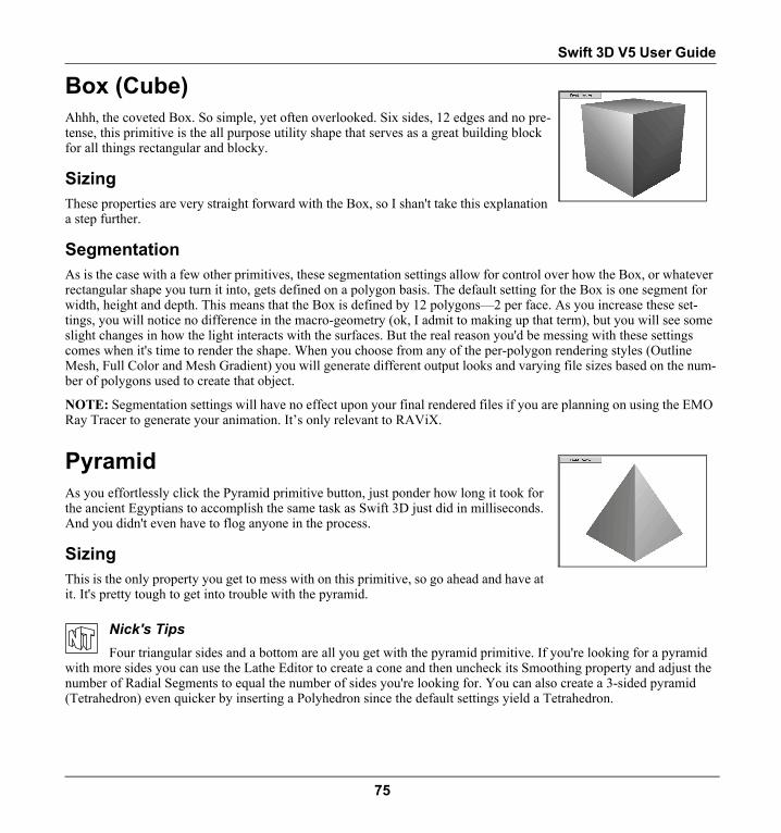
Swift 3D V5 User Guide
Box (Cube)
Ahhh, the coveted Box. So simple, yet often overlooked. Six sides, 12 edges and no pre-tense, this primitive is the all purpose utility shape that serves as a great building block for all things rectangular and blocky.
SizingThese properties are very straight forward with the Box, so I shan't take this explanation a step further.
SegmentationAs is the case with a few other primitives, these segmentation settings allow for control over how the Box, or whatever rectangular shape you turn it into, gets defined on a polygon basis. The default setting for the Box is one segment for width, height and depth. This means that the Box is defined by 12 polygons—2 per face. As you increase these set-tings, you will notice no difference in the macro-geometry (ok, I admit to making up that term), but you will see some slight changes in how the light interacts with the surfaces. But the real reason you'd be messing with these settings comes when it's time to render the shape. When you choose from any of the per-polygon rendering styles (Outline Mesh, Full Color and Mesh Gradient) you will generate different output looks and varying file sizes based on the num-ber of polygons used to create that object.
NOTE: Segmentation settings will have no effect upon your final rendered files if you are planning on using the EMO Ray Tracer to generate your animation. It’s only relevant to RAViX.
PyramidAs you effortlessly click the Pyramid primitive button, just ponder how long it took for the ancient Egyptians to accomplish the same task as Swift 3D just did in milliseconds. And you didn't even have to flog anyone in the process.
SizingThis is the only property you get to mess with on this primitive, so go ahead and have at it. It's pretty tough to get into trouble with the pyramid.
Nick's TipsFour triangular sides and a bottom are all you get with the pyramid primitive. If you're looking for a pyramid
with more sides you can use the Lathe Editor to create a cone and then uncheck its Smoothing property and adjust the number of Radial Segments to equal the number of sides you're looking for. You can also create a 3-sided pyramid (Tetrahedron) even quicker by inserting a Polyhedron since the default settings yield a Tetrahedron.
75

Chapter 7 | Primitives
ConeThe cone is really just a relative of the cylinder, with the obvious difference that it comes with a point on top.
RadiusThe top and bottom radius settings allow you to turn your cone into something that I really don't have a definition for. It's sort of like the various forms of progeny that would be generated if a Cone mated with a Cylinder, not that we condone that type of behavior with our primitives. In fact, there's a strict fraternization policy implemented within Swift 3D, but these controls allow you to circumvent our mandated rules.
You'll also notice that massaging these controls can easily create a cylinder, but I assure you that we also have a strict rule regarding the cloning of primitives (and massaging for that matter).
SegmentationAlthough the two cone segmentation settings work as you'd expect, they will most likely be used for different pur-poses.
AxialI guarantee that when you start to adjust the axial segmentation of the cone you're going to mutter, “Now there's a use-less feature,” but I feel obliged to tell you otherwise. Although you will not be noticing any shape change in the object, when it comes time to render the object, you may be more interested in this control. As you change this setting, you are increasing and decreasing the number of polygons that make up that object. When you choose from any of the per-polygon rendering styles (Outline Mesh, Full Color and Mesh Gradient) you will generate different output looks and varying file sizes based on the number of polygons used to create that object.
RadialAlthough you can use the radial segmentation to control your polygon count just like the axial control, your use for this control is most likely going to be adjusting the actual geometric shape of the cone. By bumping this setting lower and lower, you can create a cone that becomes more faceted (made up of more surfaces), which can be very beneficial when it comes to rendering your scene with certain output styles.
ClosedBy choosing to close the Cone, you are telling Swift 3D to place a cap on the bottom of it. If you uncheck this option, you will be able to see into the cone as if it were created with paper rather than clay. And if you increase the top radius above zero, you will be able to see right through the object from certain camera angles.
76

Swift 3D V5 User Guide
CylinderA variation of the Cone, the cylinder is your all-purpose tube. Great for building DNA chains architectural columns, and even useful when you want to place something on a pedestal. Simply defined by a radius and length, they're not quite as powerful as cones, but certainly convenient when someone asks you to model a roll of toilet paper (hey, it could happen).
Radius and LengthThe radius setting controls how thick the cylinder will be and the length setting controls how long it will be. If you're looking to adjust both parameters proportionately you're probably better off doing so using the Scale Mode button.
SegmentationPlease see the corresponding section under the cone primitive description because any adjustments you may want to make here will affect your cylinder's geometry and rendering appearance exactly as they would a cone.
TorusTorus. Ring. Doughnut. Whatever you want to name this thing, you know what I'm talking about, even though my spell checker does not.
Radius The Minor Radius is the distance from the center of the shape to the inside surface of the torus. If you increase this setting without changing the Major Radius you will make your Torus more slender.
The Major Radius is the distance from the center of the shape to the outside surface of the shape. If you increase this setting without changing the Minor Radius you will make your Torus fatter.
SegmentationThe Segmentation Minor Radius controls the number of times the circular lines that define the tubular nature of the Torus are segmented. If you decrease this number, the shape will become more angular in its cross section.
The Segmentation Major Radius controls the number of times the circular lines that define the roundness of the Torus are segmented. If you decrease this number, the shape will become more angular in its circumference.
77

Chapter 7 | Primitives
PlaneWe threw this ultra-primitive primitive into Swift 3D for one sole purpose—Shadows. You may very well find other uses for this object, and for that I commend you. But the bottom line is that planes work great for creating a surface to cast a shadow onto. Throw one of these bad-boys under your animation, check that Shadow option before rendering and you've got some big-time eye candy. And, keep in mind that with both the SWFT and the SWF export file formats you will have access to just the shadows within an animation as either their own separate layer or as a separate object.
Sizing and SegmentationPlease see the corresponding section under the Box primitive description because any adjustments you may want to make here will affect your plane's geometry and rendering appearance exactly as would the surfaces of a Box.
PolyhedronWhen primitives are born and start learning their way around the world of 3D objects, they soon come to the realization that they wished they were a Polyhedron. To be a Polyhedron is to be anything and everything, while still maintaining its coy demeanor within the Swift 3D interface. Who would have thought one button could be so power-ful. The only thing other primitives don't lust after is having the name polyhedron.
If you break down the word to its integral parts, you'll quickly realize that the confus-ing nomenclature is just a smoke screen for ‘many sided object.’ With this in mind, you can now click on that button and know exactly what you're getting into—a thing with a bunch of sides. But if you leave it at that you miss out on all the fun. With just a little bit of extra information you'll find yourself spitting out 22 letter words that will impress your friends. Or they might just get all glassy-eyed and start considering a quest for new friends.
78

Swift 3D V5 User Guide
Loosely defined, a polyhedron is an arrangement of flat surfaces (polygons) such that two and only two surfaces meet at any given edge, making it possible to traverse the surface of the polyhedron by crossing its edges and moving from one surface to another until all surfaces have been traversed by this continuous path. Whew.
What that really means is that Polyhedra (plural of polyhedron) come in many shapes and sizes. These geometrical variations can be broken up into polyhedron families, which I will describe as soon as I can borrow that Geometry textbook from the engi-neers again.
But the true power of this primitive comes ex-post insert. The versatility of the poly-hedron lies within the confines of the Properties Toolbar. With a little bit of tweak-ing, you'll be whipping out Rhombicosidodecahedrons in less time than it takes to say Truncated Cuboctahedron.
Polyhedron FamiliesFirst, let's discuss the five basic shapes that make up the starting points for all the aforementioned variations of the polyhedron. The Tetrahedron, Cube, Octahedron, Dodecahedron, and Icosahedron (the fabulous five) all share a couple of similar properties. Their faces are all made up of the same geometric shapes and all of their vertices are identical. This group of objects is known as the Platonic Solids and you'll recognize their names in the Properties Toolbar once you place a Polyhedron into the scene.
TetrahedronThe fundamental shape of a Tetrahedron, the most basic form of polyhedron, is a solid object made up of four equilateral triangles. It's like a pyramid, but with one less side. The default geometry for the Tetrahedron family is a tetrahedron (go figure) but you can create many different shapes with some fiddling of the controls we'll talk about shortly.
Cube/OctahedronThese two shapes have a distinct relationship and it goes beyond the fact that their number of sides is divisible by four. The Cube is the default geometry that appears when you insert the Polyhedron and select this family. To get to the Octahedron shape, you need to do some adjustments within the P and Q settings, but that's a whole differ-ent world so for now you can just take my word for it.
79

Chapter 7 | Primitives
Dodecahedron/Icosahedron
Again, we find two distinct shapes with a strong relationship to each other. The default geometry that appears when you insert a Polyhedron and select this family is the Dodecahedron, a 12-sided object consisting of faces that are all pentagons. With some modest adjustments you can quickly turn this shape into an Icosahedron, which is a 20-sided object made up of all triangles.
Star 1Now we begin the crazy journey into the realm of Stellated Polyhedra, which are vari-ations on two of the platonic solids but with star-like characteristics. The default geom-etry of Star 1 is an Icosahedron that has had each of its faces pulled out from the center of the object. In other words, if you were to create a vertex in the center of each trian-gular face of an Icosahedron and drag it away from the center of the object, Star 1 is what you'd end up with. If you need a term you can remember, try 20-pointed star, because that's the default construction of a Star 1.
Star 2Star 2 works under the same principles of Star 1, but its default geometry is based on a Dodecahedron where each face that the vertex gets pulled from is a pentagon rather than a triangle. In this case you end up with a 10-pointed star. By the way, don't go asking any Geometry professors for the definition of a Star 1 or Star 2. As best I can tell, the names were invented by a frustrated U.I. designer who was having a difficult time fitting the word ‘Great Stellated Dodecahe-dron’ into a dialog box.
Family ParametersI really had no idea what we were getting into when the Polyhedron was slated for construction within Swift 3D. Little did I know that one button on our interface could lead to such a communication quandary. It took me two days of research just to determine that the Family Parameters of a polyhedron (also known as Ps and Qs) were virtually inde-scribable. But that's not going to stop me from trying.
P and Q
The P parameter is directly related to the number of faces the object has, and the Q parameter is directly related to the number of vertices that exist on the object. By adjusting either of these two settings, you can generate an
unbelievable amount of variations of the Platonic Solids.
Unfortunately, the P and Q settings are only directly related to the faces and sides of the object, but not exactly repre-sentative of those numbers. What this means is that instead of setting those parameters exactly as you see fit, your best bet is to start playing around and see the results. In most cases, the three settings you can actually predict how the results are going to look like are the two extremes and the midpoint.
There are some basic things you want to pay attention to as you start tweaking your default objects.
80

Swift 3D V5 User Guide
• The range of each setting is between 0 and 1.• The two values added together cannot exceed 1.• The two extremes occur when either setting is set to 1 and the other is at 0.• The midpoint occurs when both settings are set to 0.
Let's say you insert your Polyhedron (which will give you the Tetra) with a default setting of P=0 and Q=1. This is a 100% pure Tetrahedron. As soon as you start adjusting either the P or the Q parameter, you no longer have a tetrahe-dron, but rather a variation of the tetrahedron shape. Now the interesting thing about this particular shape is that when you go to the other extreme, where P=1 and Q=0, you also end up with an exact tetrahedron. This is the only family where this occurs and it's also the reason why there is only one name under this family category.
Moving on to the Cube/Octa, we start out with the same default setting of P=0 and Q=1 and you have a perfect cube. Now when you choose the other extreme you will end up with the Octahedron, which is the main reason these two objects are lumped together in a family.
Finally, the Dodec/Icos arrives into the scene with the standard P and Q settings and when you crank the P setting to equal 1, you change your perfect Dodecahedron to a perfect Icosahedron.
Scale AxisAnd now the really dense fog rolls in. The Scale Axis is still based on Ps and Qs with the addition of some Rs for con-fusion sake. These settings allow you to push and pull faces of your polyhedron in a similar fashion to what the Star 1 and Star 2 do. In fact, if you start from the Dodec/Icos family you can quickly achieve the Stellated Polyhedron default geometry. But once you start cranking these settings in conjunction with variations of the P and Q Family Parameter you'll quickly realize that there is no end to the crazy shapes the Polyhedron can generate.
One important thing about the Scale Axis settings is that P, Q and R each control a different type of surface. There can be three basic surfaces on a Polyhedron: triangles, squares and pentagons. If your shape has one or two types of sur-faces, only one or two of the Scale Axis settings will have any effect on the faces of the shape. When the shape has all three types of faces, P, Q and R will all be active.
RadiusNow back to something we can all relate to. Adjust the radius of a Polyhedron and it will get bigger or smaller. And I didn't even have to research that one.
81

Chapter 7 | Primitives
82

Chapter 8 Text
OverviewI'm not sure about you, but my first experience with 3D text was when I started going to see Hollywood movies in the theatres. When I saw a deeply extruded rendition of the Star Wars title with that extreme perspective that tapered quickly towards the vanishing point, text suddenly became much more than trying to achieve a perfect cursive letter ‘B’ in 3rd grade. They became art, more like sculptures than a bunch of letters thrown together, more of an outlet for creativity rather than a model for replication. And with the massive increase in font selection through the boom in personal computing, sud-denly you could convey emotions and moods with just the mere visual representation of your words. Wow, I'm sorry to come across as a total word geek, but that was some cool stuff for me.
So here we are in the 21st century with Swift 3D, certainly not the first 3D font rendering software, but an exceptional solution for turning 3D text into vector-based animations. Within Swift 3D, any TrueType or PostScript font you have installed on your computer can be automatically turned into an extruded and beveled 3D object.
Inserting a Text ObjectThere is little mystery to getting started with text. Simply click the Create Text button on the Main toolbar and the word “Text” appears in your scene, which is when the fun begins.
Text Property PageAfter you complete the grueling task of inserting the word “Text” into your scene, unless by some cosmic coincidence you are building a Web site all about text, you will most likely want to do a bit of personalizing to meet your text needs. This can all be done from the Text property page, which by default is selected after you hit the Create Text but-ton.
83

Chapter 8 | Text
FontUse the Font dropdown menu to choose the style of text you desire, using the pre-view function to guide your selection. The default font can be adjusted by going to Setup > User Preferences.
TextYou can replace the text with your own by highlighting the word in the Properties Toolbar and typing whatever you like.
AlignmentYou can adjust the alignment of your text with the Alignment buttons shown.
Character MapThe Character Map button gives you a display of all the weird characters that come with each font, but aren't shown on your keyboard. For example, select the Wingdings font in the font dropdown list, and then click on the Character Map button to see a ready-made list of symbols.
Nick's TipsWingdings are sweet. That's right, Wingdings, Webdings, Dingbats—all cool in my book. They quickly extend
the versatility of Swift 3D by giving you a ton of 2D objects that can be extruded in a heartbeat via the Text button. And after a quick Web search I found tons of picture-based fonts similar to Wingdings, all for free. Adding these types of fonts is sort of like building your own personal 2D library. If you’re feeling industrious you could even create your own fonts made up of custom shapes.
To work with text properties:1. Click on the Text object button on the Main Toolbar.2. Highlight the word Text in the Text box in the Properties Toolbar (by either clicking and dragging your cursor
over the letters or double clicking anywhere on the text).3. Type in any word.4. Go to the Font dropdown list and choose a new font.5. Hit the Character Map button, find the exclamation point and click on it to insert it into the Text box.6. Click on the 3 different alignment keys to watch your text realign itself in the Viewport.
84

Swift 3D V5 User Guide
Bevels Property PageBevels refer to the transition between the front and back surfaces and the side sur-faces of your text. When you are using 3D text, adding bevels will create another sur-face for light to reflect off of, thus creating a more interesting effect. Swift 3D allows you to apply five different types of bevel effects.
Styles• Square: A 90-degree angle, giving your text only three total surfaces: front,
side and back (i.e. no bevel).• Beveled: A 45-degree angle, as if you ran a knife along the front corners of your
text. This is the default style.• Outer Round: A smooth, convex, rounded transition between the front surface
and side surface, as if you sanded the front corners down.• Inner Round: A smooth, concave, rounded transition, as if you gouged out the
front corners of your text.• Step Down: As if you glued your text to the front of a larger version of your
text.
NOTE: You are not actually removing material from the characters, as you would when working with wood, but rather you are adding thickness to the areas without the bevel in order to create them. This means that as you increase the depth of your text you will be increasing its size as well, which may change the overall character of your font.
Bevel GalleryBevels can also be dragged and dropped onto Text or Extrusions from the Bevel Gallery.
Nick’s TipsThere are two things I feel obliged to mention at this juncture. First, don’t go typing in your company’s Mis-
sion Statement and expect to have a file that will stream at 28.8 kbs. Text, especially with a fancy font applied, has a lot of geometrical detail when it’s converted to a 3D object so it can get big, fast. Second, bevels are cool, but they also can boost your bandwidth consumption. I recommend sticking to the 45 degree bevel because the other ones tend to need a higher level fill option when rendering in order to be visible. Unless of course you’re rendering to raster, which in that case knock yourself out!
85

Chapter 8 | Text
DepthWith the Depth control you are manipulating how quickly the text makes your desired transition from front and back surfaces to side surfaces. The higher the number, the longer the transition, ergo, the more depth you apply to your bevel, the thicker your text becomes. Get carried away and you've got some funky looking stuff, not that funky is a bad thing.
If you are significantly increasing the bevel size (around 5.0 or higher), you may stop seeing any changes to your bev-els until you go and increase the Depth under Sizing.
FaceBy default, the bevels are applied to both the front corners and the back corners so you will see the same thing going on when you view the backside of your text. To control which faces are beveled, choose front, back or both under the Face options.
To work with bevels:1. Click on the Text object button on the Main Toolbar.2. In the Properties Toolbar, select the Bevel Property Page.3. Click on the Beveled dropdown list and choose a different bevel option (not square).4. Key in 0.050 in the Depth box (or use the scrollers).5. In the Rotation Trackball, drag your cursor across the trackball until the back of the text comes into view.6. Click on the Front Face button. Notice that the backside of the Text is no longer beveled.7. Click the Reset Rotation button on the right side of the Rotation Trackball.
NOTE: The default Bevel Style and Depth can be adjusted by going to Setup > User Preferences.
SmoothnessThis slider controls how accurately curves are drawn on your text. If you adjust towards Fine, your curves will smooth out, but the amount of lines it takes to render the text increases, and so does your file size. Adjusting towards Coarse will make any curves appear more angular and reduce file size. The general rule of thumb is “leave it alone unless you have a good reason not to.”
Mesh QualityThis control is there to allow you some control over the geometry created when you extrude text and 2D artwork. The default polygonal construction of these objects typically lead to some very narrow polygons where there are curved edges. This can sometimes lead to some inconsistencies after rendering and importing into Flash. If you experience any of these problems, you should adjust this slider to a higher level of Mesh Quality and try rendering again. Another side effect is that when you jack this setting up, you’ll have more detailed lighting effects when you are rendering with Mesh Gradient Shading.
86

Swift 3D V5 User Guide
Sizing Property PageYou have five controls over the sizing of Text. Width and Height are pretty straightfor-ward. Depth allows you to control how deeply extruded your text objects are. Inter Character and Inter Line control the distance between each character and each line of text.
Any numerical changes will use the center of the text as a baseline. So if you increase the depth, the front of the text will move towards you (if it's facing the camera) and the back of the text will move away from you.
NOTE: The default Depth applied to Text and Extrusions can be adjusted by going to Setup > User Preferences.
Editing Characters IndividuallyWhen your create a text object, it is considered one main object that consists of individual grouped characters, but the characters within the word are considered children and can be somewhat manipulated independently.
To edit characters individually:1. Click on the Text object button located on the Main Toolbar.2. Hold down the CTRL key (Win) or OPTION key (Mac) while clicking on the ‘e’ character. Notice that a bound-
ing box now appears just around the ‘e’, and only the ‘e’ appears in the Rotation Trackball.3. Once you have that character selected you can apply different properties to it within the Properties Toolbar, so go
to the Sizing page and increase the letter’s height.4. Go to the Material Gallery and while holding down the CTRL key (Win) or OPTION key (Mac), drag-and-drop a
new material on just the ‘e.’5. Go to the Animation Gallery and while holding down the CTRL key (Win) or OPTION key (Mac), drag-and-drop
one of the rotation animations on just the “e.”6. Click on the Play button and watch just the ‘e’ rotate.
Convert Text to PathsThis is a great feature that provides you with the ultimate control over your text. When you click the Convert Text to Paths button in the main toolbar, your text is no longer a font, but is now treated as an extruded object that can be edited in the Extrusion Editor. For those of you familiar with programs like Adobe Illustrator or Macromedia Freehand, this is the same thing as inserting text into those programs and then converting it from a font to outlines.
87

Chapter 8 | Text
What makes this feature extra sweet is that the morphing of paths is supported by our Animation Timeline. We go into the details of Path Morphing in the Animation chapter.
It’s important to note that this conversion is a one way street, so make sure your text contains all of the letters you eventually want to work with in the Extrusion Editor before you click this button.
Also, if you’ve made any changes to individual characters of a text string, like applying a specific material, you will lose those changes upon conver-sion.
Working With Text Objects in Advanced ModelerText can be brought into the Advanced Modeler if you want to further manipulate its mesh. This is obviously a great feature, but one thing you need to realize is that as soon as you click on the Edit Mesh button in the Advanced Mod-eler, the text is converted to an editable mesh and you no longer have access to the object’s text properties (font, bevels, etc.). A warning dialog will appear in order to remind you of the implications and to prevent you from inadvertently converting text into a 3D model. You can use the Undo function in the Advanced Modeler to reverse this action if you decide to go back to your original text object.
88

Chapter 9 Extrusion Editor
OverviewExtrusions are a non-3D guru’s best friend, which probably explains why I cozied up to our Extrusion Editor pretty quickly when it first arrive on the scene. I mean c’mon, would you rather spend your time learning what NURBS and splines are all about, or would you feel more comfortable grabbing a pen, sketching out a shape and having it instantly appear in your scene as a 3D object. Not to mention all of the familiar concepts like Bezier curves, control points and a nice flat surface to draw on. All these things add up to one of the most powerful modeling tools Swift 3D offers.
And for those of you with zero 3D experience, let me throw a quick explanation of what an extrusion actually is. It's when you take a flat, 2D shape and extend its Z depth. As a most basic example, let's start with a single 8½” x 11” piece of paper. That's your original 2D shape. Now add 499 pieces of the same size paper to the stack and wrap it so it becomes a single unit. That's your extruded object. (Actually it's a ream of paper, but hey, I'm trying to prove a point here.) As you add or subtract pieces of paper to that stack, you are determining how thick your object becomes. That thickness is its Z depth.
So Swift 3D’s Extrusion Editor may not measure up to an application like Adobe Illustrator and it may not offer total modeling power like the Advanced Modeler, but man is it a perfect hybrid tool for folks like myself (and maybe you) who can draw stuff with a Bezier Pen. And with the additional abilities of bringing 2D vector files into the Extrusion Editor as well as animating paths with the built-in Animation Timeline, you’ve got yourself a great ‘utility player’ in the big game of 3D modeling and animation.
89

Chapter 9 | Extrusion Editor
How It WorksThe basic concept is that once you draw a shape within the Extrusion Editor interface, the extrusion appears immediately in the Scene Editor with a default depth of 0.050 units.
The Extrusion Editor merely exists to create the original shape. Once the actual extrusion appears in the Scene Editor, you will be able to adjust all of the extrusion's properties like depth, bevels, materials, etc. through the Properties Toolbar.
You should also take notice of the differences between a Bez-ier Pen Tool from other applications and that of Swift 3D. As you begin drawing, you will need to select what type of point you want created via the three buttons on the top of the Extru-sion Editor Interface: Corner Point, Curve Point and Tangent Point. But I'm getting slightly ahead of myself.
Main ToolbarPen ToolIt all starts by selecting the pen tool (selected by default when you enter the Extrusion Editor) and choosing a place on the grid to start drawing. By clicking the Pen Tool you are telling Swift 3D that you are ready to begin drawing.
Selection ToolThis tool will allow you to select individual and groups of points to further manipulate your shape once it has been drawn. By clicking the Selection Tool you are telling Swift 3D that you are ready to start editing your drawing.
Corner PointWhen this button is depressed, every point you create will be an Corner Point with no information defining how the path enters or exits that point. If I create a series of Corner points, they will all be connected with perfectly straight lines.
Curve PointThe Curve Point has much more information associated with it than the Corner point. Curve points are defined by something called a Bezier curve whereby you have control over the shape of the line entering and exiting the point. Although you can control the entry and exit, the two halves of your curve are linked to each other so positional changes to one half of your point may have an effect on the other half of the Bezier curve. The typical application of Curve Points is to create two lines that join together at the point in a smooth fashion.
90

Swift 3D V5 User Guide
Tangent PointThese are very similar to the Curve point but they allow you to control each side of the curve's control points separately. The tangent point is designed to allow your line to enter and exit the point with completely differ-ent paths. The typical application of Tangent Points is to create two curved lines that join together in an angular fashion.
Close Shape ButtonThis button is designed to be a time saver. Although not completely necessary, it's always a good practice to close your shapes when working within the Extrusion Editor. With that in mind, the Close Shape button offers a quick way to close your shape when you're ready to create that final line segment. Certainly you can do it manually by creating your final point directly on top of your very first point (a “+” sign will appear when you’re directly on top), but the Close Shape button will accomplish the exact same thing.
Magnifying GlassJust imagine if Sherlock Holmes had licensed his classic investigatory tool to the software companies of the world. A simple royalty structure would have done wonders for him and Watson. Swift 3D's zoom tool works like this. Grab the tool, click to zoom in and right click to zoom out. Wherever you click on the grid determines the area that gets magnified or unmagnified.
Undo/Redo ButtonsUndo/Redo can be accessed through the Edit menu or shortcut commands, but if you're a button pusher you can take a crack at the Undo/Redo buttons.
Shape ToolsThese buttons provide you with a quick and easy route to some common extrusion shapes you might be interested in using in your Scene. Or they may be a good starting point for the creation of something a little more custom. Either way, a click of the button inserts the proper path into the editing interface with all of the associ-ated control points.
N-GonThe N-gon is a more flexible version of these shape tools. The button itself shows a penta-gon, but by selecting from the dropdown list you can designate the inserted shapes as any-thing from a triangle to an octagon.
Animate ButtonThe Animate button must be toggled on in order to activate the Extrusion Editor timeline.
91

Chapter 9 | Extrusion Editor
Working with Extrusions from the Model GalleryThe Model Gallery comes with a library of extrusions that you can click-and-drag into the Scene Editor and bring into the Extrusion Editor for further editing. The extrusions that are shipped with the program reside under the Extrusion Tab in the Model Gallery. While the thumbnails provide you with a view of the finished extruded object, these shapes are actually just bezier paths that you can tweak into something all your own or use as is.
To add an extrusion from the model gallery:1. In the Scene Editor, click on the Model Libraries button, select the Extrusion Tab and choose a model from the
gallery.2. Click on the preview window and drag the cursor into either Viewport. 3. Go to the Extrusion Editor and the Bezier path of that shape will appear centered around the (0, 0) coordinate.4. Use any of the Extrusion Editor tools to edit the path.5. Click back on the Scene Editor tab to view the changes to the object.
You can also save your own extrusion to the Model Gallery so that it is accessible for future use in any open Swift 3D project.
To save an extrusion to the model gallery:1. Once you have finished creating or editing an extrusion, return to the Scene Editor.2. With the extrusion selected in the Viewport, choose File > Save Model.3. This will bring up the Save Model dialog, from which you can choose a name and location within the Model Gal-
lery for the extrusion. All extrusions stored in the Model Gallery get saved to the .t3om file format.
Editing Gallery ContentsAn extrusion added to the Model Libraries can only be edited in the Extrusion Editor workspace (unless you choose to convert it to a mesh and edit it in the Advanced Modeler). Once an extrusion is placed into the scene it no longer has any connection to the original stored back in the model gallery, so when you finish editing you must go through the steps for saving an extrusion to the gallery. If you do not desire two copies of the extrusion, either overwrite the previ-ous extrusion by using the same name when saving, or simply delete the previous version from the gallery.
You can right click (Win) or CTRL + click (Mac) on the palette window surrounding the thumbnails to bring up the Gallery Setup dialog, from which you can delete, rename or relocate any gallery content. For information on how to share Gallery content and managing Galleries in Swift 3D, see the section on Galleries in the Scene Editor chapter.
92

Swift 3D V5 User Guide
The GridThe grid is mostly there for reference rather than for numerical sizing or positioning. Each grid line in the editor is set .05 units apart. When zoomed out you will see black dashed guidelines that represent 1 unit. A relationship does exist between the location of a path in the Extrusion Editor and where the extrusion is positioned when it is brought into the Scene Editor. The location of the extrusion in the Viewport will depend on where the object was drawn in relation to the (0, 0) coordinate in the Extrusion Editor. For example, if the path is centered around X = 0 and Y = 0, the extrusion will be centered in the Scene Editor as well. If the path is drawn in the lower right quadrant of the grid, the extrusion will appear in the lower right quadrant of the Viewport.
What is the meaning of all this? This placement issue is only important if you plan to apply a bitmap texture to your extrusion. The location from which a bitmap image begins to wrap onto an extrusion is dependent upon where the path was drawn in relation to the (0, 0) coordinate. Specific details regarding bitmap wrapping to extrusions can be found in the chapter on Materials. It is also notable that any extrusion taken back into the Extrusion Editor for further editing will always be centered at (0, 0), no matter where it was initially drawn since the Extrusion Editor has no way of remembering the original location of each extrusion.
Creating ShapesWhile it is possible that the shape you’re looking for resides within the Extrusion Gallery, there are definitely going to be many occasions when you will need to create your own shapes. We might as well start with the easiest way of start-ing out, which by using one of the shape primitives accessible through the Shape Tools located on the Main Toolbar.
To create an object using the shape tools:1. Click the button that contains the shape you want.2. Click the Scene Editor Tab to view the extrusion.
The Shape Tools can’t meet everyone’s needs, though, so let’s move on to the nitty-gritty of how to draw a shape from scratch using the Pen Tool.
To draw a straight-lined shape (parallelogram):1. Select the Pen Tool button (on by default).2. Select the Angle Point button (on by default).3. Click once on the grid 5 lines above the X/Y intersection.4. Click again on the grid 7 lines to the right of that point.5. Click on the grid 5 lines to the right of the X/Y intersection.6. Click on the grid 2 lines to the left of the X/Y intersection.7. Move your cursor directly above the first point created and click when
you see the ‘+’ symbol appear next to your Pen Tool (or click the Close Shape button).
8. Click the Scene Editor Tab to view the extrusion.
93

Chapter 9 | Extrusion Editor
To draw a curved-line shape (egg):1. Select the Pen Tool button.2. Select the Curve Point button.3. Click once on the grid 6 lines above the X/Y intersection.4. Click again on the grid 3 lines to the right of the X/Y intersection.5. Click again on the grid 3 lines below the X/Y intersection.6. Click again on the grid 3 lines to the left of the X/Y intersection.7. Move your cursor directly above the first point created and click when you
see the ‘+’ symbol appear next to your Pen Tool.8. Click the Selection Tool button.9. Select your first point and then click-and-drag on the right Bezier handle
to make your curve guide run parallel with the X axis. Position the end square of the right handle on the grid 2 lines to the right of the Y axis, and the end square of the left handle 2 lines to the left side of the Y axis.
10. Continue around the shape, positioning the Bezier handles as shown in the diagram above until you have a nice egg shape.
11. Click the Scene Editor Tab to view the extrusion.
To draw a multi-point-type shape (starburst):1. Select the Pen Tool button.2. Click the Angle Point button.3. Click on the grid 4 lines above the X/Y intersection.4. Select the Tangent Point button.5. Click on the grid 2 lines to the right and 2 lines above the X/Y intersection.6. Select the Angle Point button.7. Click on the grid 4 lines to the right of the X/Y intersection.8. Select the Tangent Point button.9. Click on the grid 2 lines to the right and 2 lines below the X/Y intersection.10. Continue the process to create the left side of your shape, making sure to close
the shape at the end.11. Select the Selection Tool.12. Select the first Tangent Point you created and drag each of the two Bezier han-
dles onto the X/Y intersection.13. Continue that process for the remaining 3 Tangent Points.14. Click the Scene Editor Tab to view the extrusion.
Nick's TipsDue to the manner in which Swift 3D lays down Curve Points and Tangent Points, I highly recommend using
the following strategy when creating anything but the most basic symmetrical shapes: sketch it out with the key control points, choosing your point type as you go. Don't pay attention to the overall shape of the object with your original run through, because you'll only get frustrated. Once you've laid down the basic shape with your points, then you can go back through and make all the necessary adjustments to your point locations and Bezier curves, adding and subtracting points as needed.
94

Swift 3D V5 User Guide
Editing Your ArtworkThere are a variety of ways to edit your paths after they have been created.
Editing PointsSelecting PointsTo select an individual point, use the Selection Tool and click on the point. To aid in selecting points, the cursor has a hover state when it is over a point that is available to be selected.
Once you see the cursor change to this state, simply click down on the point to select it. The point will turn red when it's selected.
To select multiple points, hold down the SHIFT key while selecting individual points. The most recent point selected will be red and the additional selected points will become black. CTRL + click (Win) or OPTION + click (Mac) will deselect any errant points that may have been selected.
To perform either of these functions you can also click-and-drag a marquee box around single or multiple points.
Moving PointsTo move individual or groups of points around within the Extrusion Editor simply click-and-drag them to a new loca-tion. Only selected points will move.
If you would like to constrain the axis along which your points move, holding down the SHIFT key before moving them will constrain their movement along the X axis or Y axis.
Adding and Deleting PointsTo add additional points to a shape, select the Pen Tool, choose the point type you would like to add (Point, Curve Point or Tangent Point) and then click on the existing path where you want that point to be inserted. To delete a point or multiple points, select them and hit the DELETE key. You can also use the Menu command of Edit > Delete.
Changing PointsTo change the point type of individual or multiple points, select the points you'd like to convert, and then select the point type you'd like to convert them to from either the Main Menu or the Point Properties dialog. Short cut keys exist for all of the point types, which can be very convenient as well.
95

Chapter 9 | Extrusion Editor
Point PropertiesThis dialog is for the control freak in all of us. If you need to know that your point is EXACTLY on the Y-axis this is where you come to for answers. To access the dialog you can right click (Win) or CTRL + click (Mac) anywhere within the grid area and choose Point Properties form the context menu, or you can select a point and choose View > Point Proper-ties.
TypeThis section of the Point Properties allows you to alter the Point Type of all the points you have selected.
PositionThe position control allows you total control over the positioning of your points on the X and Y coordinate grid. If you have multiple points selected, the Position control will show you the coordinates of the point that is colored in red.
Keyboard Nudge IncrementWithin the Extrusion and Lathe Editors you can manipulate selected points and groups of points by using the arrow keys on your keyboard. Each time you click an arrow it will move the point(s) the number of increments designated within this Point Properties dialog. If you feel the need for a more or less refined nudge ability, this is the place to make those related changes.
Editing PathsSelecting PathsBefore you can edit a path it must be selected. To select an entire path with all of its points and their related control handles, you can double click on the path itself, at which time a red bounding box will surround it. You will see a little icon (it looks like a seagull to me) appear when your cursor is hovering over a selectable path. Once a path is selected, you can drag it to any spot in the Extrusion Editor.
Free Transform Tool CursorsThe red bounding box that surrounds a selected path has eight sizing handles that allow you to adjust the path in a way dependent on the active tool. The sizing handles are located on each corner and in the middle of each side. When the cursor is placed over or near these points, the cursor has a hover state that will change to display the available trans-
96

Swift 3D V5 User Guide
form tool.Once you see the cursor change to this state, simply click down on the point to activate the tool, at which point the red bounding box will change to a blue dotted line, giving you a visual representation that the tool is enabled.
NOTE: Any path transformations performed using the Free Transform Tools cannot be animated. When working in Animation Mode, using a Free Transform Tool on an animated path will influence the entire animation and not only the currently selected frame. For example, if you have an object that path morphs while moving from right to left, and you then rotate the object 180º within the Extrusion Editor, the object will now move left to right.
Scaling Paths
Placing the cursor over any of the sizing points of the bounding box will activate the Scale Tool. The path will stretch in whichever direction the handle is dragged. To uniformly scale the path, hold down the SHIFT key while dragging one of the handles. To constrain scaling to the center of the selection, hold down the CTRL key (Win) or OPTION key (Mac). When Scaling mode is active, the Scaling Mode But-ton will be highlighted.
Rotating Paths
Placing the cursor just outside of one of the four corner sizing points of the bounding box will activate the Rotate Tool. The path will rotate in whichever direction the handle is dragged. Holding down the SHIFT key while dragging will constrain rotation to 22.5º increments.
Skewing Paths Placing the cursor just outside of one of the four middle sizing points of the bounding box will activate the Skew Tool. When over the top or bottom sizing point, moving the cursor to the left or right will skew the path in that direction. Moving the cursor up or down while over a side sizing point will skew the path in the relative direction.
Copying and Pasting PathsOnce a Path is selected, you can copy and paste the path inside of the Extrusion Editor, or you can also copy and paste the path into the Lathe Editor. Within the Extrusion Editor, only one path can be copied at one time. The path must be selected by double clicking on the path (using the seagull cursor). Once selected, you can choose to Paste in Place, which will paste the path in the same exact location or you can do a straight Paste, which will offset the path from its original location.
To copy and paste a path:1. Select a path that you want to copy.2. Go to Edit > Copy or use the CTRL + C (Win)/COMMAND + C (Mac) shortcut keys.
Scale Rotate Skew
97

Chapter 9 | Extrusion Editor
3. To paste the path in the Extrusion Editor, go to Edit > Paste or use the CTRL + V (Win) or COMMAND + V (Mac) shortcut keys. Or, use the Edit > Paste in Place option, which is SHIFT + CTRL + V (Win) or SHIFT + COMMAND + V (Mac).
4. To paste the path into the Lathe Editor, click on the Lathe Editor Tab and go to Edit > Paste or use the CTRL + V (Win) or COMMAND + V (Mac) shortcut keys.
NOTE: The paste function will not work if a path already exists within the Lathe Editor because only a single path can be present in the Lathe Editor at one time.
Working with complex shapesAlthough I threw out the “We’re not Adobe Illustrator” caveat at the beginning of this chapter, there are a few extra things that you can do within the Extrusion Editor that rank up there in the ‘pretty-cool feature’ category.
Excluding ShapesYou have the ability to punch holes in your extrusions through the process of exclu-sion. It's a simple process, really. If you have a shape within another shape, the shape within will end up becoming negative space inside of that larger shape.
A basic example would be if I draw a circle and then draw a smaller circle within the larger circle, I would create a ring. Sort of like a torus, but with hard edges. Obviously you can get much more creative than this, but the basic concept always remains the same.
It's important to note that as soon as the path of your interior shape breaks through the path of the surrounding shape you will no longer have an excluded area. Instead, the Extrusion Editor will fill the entire shape using the furthest out-side path, in this case a combination of the outer shape and the section of the inner shape that protrudes from the outer shape.
2D LoopsYou will probably come across this effect by accident as you play around with the Extrusion Editor. The way Swift 3D calculates what to fill and what not to fill has to do with complex calculations that I do not care to explain, let alone understand myself. My point is that if a path overlaps itself, you're going to get a strange geometric shape created in the Scene Editor that actually takes on more of a 2D Mobius strip type look, minus the 180 degree twist. Or maybe a bow made out of ribbon. Honestly, try it for yourself and you'll understand much better than my feeble descriptions. The only thing I can warn you about is that it's not going to look like you'd expect.
Combining and Breaking ApartThese functions need a touch of explaining to understand why they exist at all. My initial reaction to these features was, “Isn't that what the Group and Ungroup commands are all about?” When our chief engineer put his hand around my shoulder and led me into his office I knew that I was sadly mistaken. A half hour later I felt qualified to give this explanation.
98

Swift 3D V5 User Guide
When two extruded objects are grouped, there is nothing more than a loose association between them. They may be moved together, rotated together, even scaled together. But they can still have different materials applied to them and their shapes are in no way related to each other.
When objects are Combined, they are related to each other mathematically through their paths. In other words, even though two or more shapes that have been combined do not share any paths, they are technically one object, meaning that they must share all of the same properties, like materials, bevels, sizing, etc. Conversely, when these shapes are broken apart again, they become separate entities completely. Really the Combine function in our program is similar to the Make Compound Path function in Adobe Illustrator or the Combine > Blend function in Macromedia Freehand.
When two or more paths are drawn into the Extrusion Editor simultaneously they will automatically take on the Com-bined setting. If you do not want multiple extrusions to have the same properties then you should draw them one at a time, making sure to leave the Extrusion Editor, deselect the extrusion and then re-enter the Extrusion Editor with a blank slate.
So you're still thinking “And I'm interested in this information because….?” That's OK, here's the skinny:
• When two or more extruded objects are combined, you can alter all of their Properties at once. For instance, if you have a multiple-shape extrusion and want to bevel all of the shapes at once, you would need to combine them beforehand.
• To apply different materials to multiple extruded objects, they must first be broken apart.• When you want to punch an object out of another extruded object, they need to be combined to accomplish this. If
they are not, they will simply be overlapping objects.• When you draw two or more objects at once within the Extrusion Editor they will automatically be combined.• When you combine two or more objects that lie on different planes of rotation, they will all be realigned to coin-
cide with the axis of the first object created.• When two or more extruded objects that have different Properties assigned to them are combined (for example
different materials, bevels, depth, etc.), all of the objects will assume the properties of the first object created.• Be aware that if you combine something like imported text in order to make some universal property changes, if
you break them apart again, all of the holes will become solid objects, which might not be your desired result.
Nick's TipsWith all this combining and breaking apart it's easy to get confused. So I'm going to outline a common scenario
to help you get a grasp on its practical use. Let's say I'm rebuilding the Electric Rain logo in the Swift 3D extrusion edi-tor. The three factors that I need to deal with are as follows: The right side section has two holes punched through it. The two sections have different materials applied to them. Both sides need to be extruded and beveled the same amount. Here's the process I'd use:
1. Create the two main sections with outlines in the Extrusion Editor.2. Go to the Scene Editor and adjust the Bevel and Depth of the Combined Object.3. Break the object apart.4. Select the right side object and go back to the extrusion editor.5. Insert the cutout sections on the right side section.6. Go back to the Scene Editor and apply materials.7. Select both objects and group them together so the logo can be animated as one unit.
99

Chapter 9 | Extrusion Editor
Editing Imported AI and EPS ExtrusionsYes, another advantage to having the Extrusion Editor on-board Swift 3D is that you can edit your 2D vector artwork imported from AI and EPS files. You may have used a 2D drawing program to create the original artwork, but having the ability to touch something up post import is incredibly convenient.
After importing your 2D vector artwork (please read the chapter on Importing AI and EPS files for more information on this process) all you have to do to edit the artwork is select your imported image and then go to the Extrusion Editor. You will see all of the associated anchor points and Bezier control handles and they can all be manipulated just as you would a native extrusion.
Nick's TipsWhile the Extrusion Editor can edit imported AI/EPS files, the Lathe Editor cannot. If you want to bring a path
originally created in another 2D program into the Lathe Editor what you will need to do is bring it into the Extrusion Editor and then copy and paste that path over to the Lathe Editor.
Path MorphingUsing the Extrusion Editor Timeline you can create anima-tions where the actual path of the extrusion changes over time. This type of animation is called Path Morphing. Since the timeline in the Extrusion Editor works almost identi-cally to the main timeline in the Scene Editor, the timeline and Path Morphing are covered in detail within the chapter on Animation.
Extrusion PropertiesOnce you take your path back to the Scene Editor your newly extruded object will come with these additional proper-ties that you can access from the Properties Toolbar.
BevelsThese properties are identical to the beveling of a text object so please refer to “Bevels Property Page” on page 85 in Chapter 8: Text.
SizingThese controls function as you would expect, allowing you to control the width, height and depth of your extruded object. If you have an extrusion with multiple objects, they must be combined before you can change all of their sizing properties at once. Otherwise you can select each object individually and adjust its size.
NOTE: The default Bevel Style, Bevel Depth and Sizing Depth applied to Text and Extrusions can be adjusted by going to Setup > User Preferences.
100

Swift 3D V5 User Guide
ScalingThis property is fully detailed in the Working with Objects chapter, but it is worth repeating here that Scale can be ani-mated while Sizing cannot.
Working With Extruded Objects in Advanced ModelerOnce you have brought your extrusion back out to the Scene Editor you have the option of taking it into the Advanced Modeler if you want to further manipulate its mesh. This is obviously a great feature, but one thing you need to realize is that as soon as you click on the Edit Mesh button in the Advanced Modeler, the extrusion is converted to an editable mesh and you no longer have access to the object’s extrusion properties (Bevels and Sizing) and you cannot bring it back into the Extrusion Editor. A warning dialog will appear in order to remind you of the implications and to prevent you from inadvertently converting an extrusion into a 3D model. You can use the Undo function to reverse this action if you decide to go back to your original Extrusion object.
101

Chapter 9 | Extrusion Editor
102

Chapter 10 Lathe Editor
OverviewDid any of you take Shop class in high school? Well I didn't either, but I hear there's this tool called a lathe that spins a piece of wood like mad and then you use various fiber-rending weapons to sculpt that dead spinning tree into a cool shape. In fact, my wife still has a lamp that she created with a lathe in 9th grade. It's god-awful ugly, but it was, in fact, created by a lathe. And now Swift 3D has an implement of creation that works on a similar basis, only in an additive manner rather than a subtractive. Oh yeah, no sawdust either.
The Lathe Editor is a powerful modeling tool that allows you to create objects that can break through the Z-axis limita-tions of 2D extrusions. And if you combine it with the Extrusion Editor and Advanced Modeler, forget about it. You'll be assembling complex models in less time than it takes to even open a high-end 3D application.
How It WorksThe short version is this: You draw a path and go to the Scene Editor to see your lathed object. If you've used a Lathe tool in another program you'll quickly understand how Swift 3D's Lathe Editor behaves. But if you're a newcomer to the lathe concept, stay with me and we'll go into a little more detail.
Drawing ToolsBefore the sawdust starts flying, let's first point out that the Bezier drawing and transformation tools of the Lathe Edi-tor are identical in function to those in the Extrusion Editor, so please refer to Chapter 9: Extrusion Editor for informa-tion on creating and editing paths.
Axis of RotationThe grid line that you'll need to pay the closest attention to is the dotted and dashed green vertical line that runs down the left side of the Lathe Editor interface. This line is the axis of rotation and is to be respected at all cost. The reason for its off-center positioning in the interface is because, in general, you only want to be drawing paths on one side of
103

Chapter 10 | Lathe Editor
your Axis of Rotation. There are exceptions we'll discuss later, but for our purposes we should keep everything on the right side of the Axis of Rotation.
Think ProfileWhen you begin drawing your path, it's important to think in terms of a profile rather than a full shape. What you are doing is creating the outside profile of your object and letting the Lathe Editor do the rest for you. Once you have defined the profile with your path, Swift 3D is going to spin that path completely around (360 degrees) the vertical Axis of Rotation. In the process, it will create a smooth surface defined by all of the points in 3D space that your origi-nal path touched as it was rotated around the axis.
Creating a Lathed ObjectThere is a classic example we can use to visually demonstrate what is so hard to verbally explain. Let's walk through the steps we would follow if our final goal were to model a wine glass.
1. Draw the shape to the right using the Bezier pen tool.2. Notice that my first and last points start on the Axis of Rotation.3. Go to the Scene Editor to view the finished product (inset image).
This should get across what I mean by drawing a profile and letting the Lathe editor do the rest. It's important to note what happens when you draw shapes that are not adjacent to the Axis of Rotation line. You will end up with a solid shape that has a vertical hole through it. The further away from the Axis of Rotation, the larger your hole gets.
Crossing the Axis of RotationDespite my warnings, no bodily harm will come to you by crossing that Axis of Rotation with your path. It's more a matter of keeping things simple. Since the process of lathing involves a 360-degree rotation, any part of the path that extends to the left of the sacred green line will end up being lathed just as if it were on the right side. In that sense you can sort of think of the axis line as a mirror and crossing the line will yield the same result as stopping your path on the axis and reflecting that angle back onto the same side.
It's quite easy to get a little crazy with this tool and start experimenting. In fact, I highly recommend it. There is defi-nitely some spatial imagination that comes into play, and you can create very complex shapes and even build 3D shapes within 3D shapes. However, you will quickly notice that all of your shapes have a distinct ‘lathed’ look about them. Because of this we have added a few features that really give you potential for more object diversity.
104

Swift 3D V5 User Guide
Working With Lathes from the Model GalleryIf envisioning object profiles is just not your specialty in life, the Model Gal-lery comes with a set of commonly used Lathes that you can simply click-and-drag into the Scene Editor. Lathes that are shipped with the program reside under the Lathe Tab. Once the lathe is brought into the Scene Editor, either use it as is or bring the lathe into the Lathe Editor and modify the path to fit your needs.
To add a lathe from the model gallery:1. In the Scene Editor, click on the Model Gallery button and choose a lathe shape from the gallery.2. Click on the preview window and drag the cursor into either Viewport. 3. Select the lathe object and click on the Lathe Editor tab. NOTE: Many of the models under the Lathe tab consist
of a group of lathed objects. Since the Lathe Editor only supports a single lathe path at a time, you must select an individual lathe from the group in order to bring it into the Lathe Editor for further editing.
4. The Bezier path of that shape will appear and you can use any of the Lathe Editor tools to edit the path.5. Click back on the Scene Editor tab to view the changes to the object.
You can also save your own lathe to the Model Gallery so that it is accessible for future use in any open Swift 3D doc-ument.
To save a lathe to the model gallery:1. Once you have finished creating or editing a lathe, return to the Scene Editor.2. With the lathe selected in the Viewport, choose File > Save Model.3. This will bring up the Save Model dialog, from which you can choose a name and location within the Model Gal-
lery for the lathe. All lathes stored in the Model Gallery get saved to the .t3om file format.
Editing Gallery ContentsA lathe added to the Gallery can only be edited in the Lathe Editor workspace (unless you choose to convert it to a mesh and edit it in the Advanced Modeler). Once a lathe is placed into the scene it no longer has any connection to the original stored back in the model gallery, so when you finish editing you must go through the steps for saving a lathe to the gallery. If you do not desire two copies of the lathe, either overwrite the previous lathe by using the same name when saving, or simply delete the previous version from the gallery.
You can right click (Win) or CTRL + click (Mac) on the palette window surrounding the thumbnails to bring up the Gallery Setup dialog, from which you can delete, rename or relocate any gallery content. For more detailed informa-tion on how to share Gallery content and managing Galleries in Swift 3D, see the section on Galleries in the Scene Edi-tor chapter.
105

Chapter 10 | Lathe Editor
Copying and Pasting from the Extrusion EditorYou also have the option of copying and pasting shapes back and forth between the Lathe Editor and Extrusion Editor. You might be wondering why this would be helpful since both editors have the same set of drawing tools. The reason is that some customers feel more comfortable creating their drawings in their own 2D drawing applications. While you can’t bring an extrusion created by importing an AI/EPS file into the Lathe Editor, you can bring it into the Extrusion Editor and cut and paste its path over to the Lathe Editor.
To cut and paste a path from the Extrusion Editor:1. In the Extrusion Editor, select a path that you want to copy by double clicking on the path.2. Go to Edit > Copy or use the CTRL + C (Win)/COMMAND + C (Mac) shortcut keys.3. To paste the path into the Lathe Editor, click on the Lathe Editor tab and go to Edit > Paste or use the CTRL + V
(Win)/COMMAND + V (Mac) shortcut keys.
NOTE: The paste function will not work if a path already exists within the Lathe Editor because only a single path can be present in the Lathe Editor at one time.
Lathe Property PageSweep AngleOnce you have the concept of rotation within your grasp, it's time to start messing with the Sweep Angle settings. In essence, this feature allows you to adjust how far the Lathe Editor rotates your path. But it opens a whole new world of possibilities and allows you to break free from that smooth, 360-degree surface that standard lathed objects tend to exhibit.
Nick's TipsThe ability to adjust the sweep angle of a lathed object should not go unnoticed. This functionality brings a
whole new modeling component to Swift 3D by offering the capability of creating smooth, but asymmetric objects. If you throw this into the modeling paradigm Swift 3D uses of assembling complex objects from smaller, and more basic objects, the Sweep Angle provides yet another arrow of creation to throw into your modeling quiver.
106

Swift 3D V5 User Guide
Segmentation
This feature brings a really nice effect to the 3D modeling table. One limitation of a standard lathed object is that there is no way to avoid creating smooth surfaces. Cer-tainly you can create edges on your object, but only along the vertical axis. The hori-zontal axis will be completely smooth until you start adjusting how many line segments your lathed object consists of.
The setting that will modify your lathed object is the Radial Segmentation. By decreasing this number you are in effect dividing up that 360-degree spin into larger and larger chunks. To view the effects, you are better off unchecking the smoothing option before you make the adjustments. The maximum you can set the Radial Seg-mentation to is 64 and the minimum is 3, since 2 segments would completely flatten your lathed object into 2D space.
Radial SmoothingThis has got to be one of my favorite Swift 3D features. After seeing the consistently smooth nature of lathed objects, being able to turn off the object's smoothing setting is a welcome feature. Now you can reduce the Segmentation of your objects, turn off the smoothing and create objects with hard edges and flat surfaces.
ClosedIf you choose a Sweep Angle of less than 360 degrees, by default your lathed object will close itself off on the ends that don’t meet, which creates a solid object. If you would like the ends to be open, simply uncheck the Closed option.
Lathe Path MorphingThe path of a lathed object is capable of being animated in a similar fashion to extrusions. There is a complete Anima-tion Timeline within the Lathe Editor interface, which makes creating a path morph just a matter of adjusting points over time. Please see the Animation chapter for more information on animating the path of a lathed object.
Working with Lathes in the Advanced ModelerOnce you have brought your lathe back out to the Scene Editor you have the option of taking it into the Advanced Modeler if you want to further manipulate its mesh. This is obviously a great feature, but one thing you need to realize is that as soon as you click on the Edit Mesh button in the Advanced Modeler, the lathe is converted to an editable mesh and you no longer have access to the object’s lathe properties (Sweep Angle, etc.) and you cannot bring it back into the Lathe Editor. A warning dialog will appear in order to remind you of the implications and to prevent you from inadvertently converting a lathe into a 3D model. You can use the Undo function in the Advanced Modeler to reverse this action if you decide to go back to your original lathe object.
4 segments - Unsmoothed
32 segments - Smoothed
107

Chapter 10 | Lathe Editor
108

Chapter 11 Importing AI and EPS
OverviewWe respect that you've worked hard to gain your 2D graphic design skills and Swift 3D is certainly not here to deny you the right to leverage that knowledge to the max. In fact, we welcome those vector files into the application in all their crisp, scalable glory. If you've got logos, illustrations, typefaces, simple shapes, complex line art, floor plans, CAD drawings or any other wonderful vector asset hanging out in that flat world of AI and EPS files, bring 'em on in. Swift 3D will make short work of pushing that 2D artwork through the old extrusion machine and before you know it you'll be looking at some bang-up 3D objects.
Upon import, all of the vector shapes in the file, including lines and fills, will be identified, given a default depth, re-colored to match their original hue and placed into the center of the Scene Editor facing the front camera. Once this conversion to 3D happens you have plenty of editing options available to you, but the hard work of converting your 2D artwork to 3D objects is officially complete.
One important thing to note is that we have been dropping the "V" word quite often here (that's "vector") for good rea-son: Swift 3D can do NOTHING with raster-based images contained within those AI and EPS files. So please verify that your file is 100% vector before you start cursing this feature. There's just no way to extrude pixels, but you do have some other potential options mentioned later in the chapter if raster artwork is all you can conjure up for import.
How to do itThe first step in the process is having a file ready to import. Swift 3D recognizes AI files up to version Illustrator CS and all EPS files, but will only acknowledge the file's contents if it is constructed of vectors. This frequently leads to confusion because although the Adobe Illustrator and Encapsulated PostScript file formats are vector-based, both sup-port the embedding of raster images. So folks will be working in programs like Adobe Photoshop or Paint Shop Pro and think that saving their file as an EPS will allow them to turn their image into a 3D object via the Swift 3D import process. Sadly, this is not the case. But at the end of this chapter, I have included some information on what to do if a raster image is all you have, as well as some other tips on getting your vector artwork ready for Swift 3D import.
NOTE: Any font data in an AI/EPS file will be converted to shapes on import, with each character being an individual object. While Swift 3D can’t do anything with bitmap images it will still let you import a file containing both bitmap and vector data, however the bitmap data will simply be discarded.
109

Chapter 11 | Importing AI and EPS
To import an AI or EPS file:1. With an open document, choose File > Import.2. Navigate to the file you wish to bring in.3. Select the file and click OK.
All objects from your original file will enter Swift 3D as one grouped object, whether or not they were originally grouped in the AI or EPS file. As such, in order to access the individual properties (bevels, sizing, etc.) of any of these objects in the Properties Toolbar, you must either Ungroup your objects using the Arrange > Ungroup feature, or, leave them grouped and CTRL + click (Win) or Option + click (Mac) on an object to select it from the group.
Nick’s TipsUpon import, it is always recommended that you cross-check the original number of objects in your AI/EPS
file (remember to count outlines and fills separately) with the number of objects in your Swift 3D document. In Swift 3D, you can determine this number by clicking on your grouped object and looking in the Selection Window of the timeline. (It will say Group of “X” Objects.)
Materials of Imported AI and EPS FilesWhen AI and EPS files are imported, Swift 3D will convert any previously applied colors into their RGB equivalents. Since Swift 3D materials are much more than just colors, here are some other components that go into creating these new materials.
• The calculated RGB color will become the new material’s base color, which is the color you see in the Color Selector box in the Color area of the Material Editor.
• A slightly darker version of the base color will be used as the material's Ambient Color. • The Reflective color will be set to black, meaning it will have no reflective properties.• The Highlight Strength and Size will be set to medium, giving it a fairly glossy look.
What all this amounts to is that you will end up with a glossy version of the original color that was imported, or at least something very close. You can adjust the properties of the converted materials afterwards using the Material Editor, and you can always replace the imported colors with something from the Material Gallery. (See chapter on Materials for additional details on this subject.)
Layers (Depth Progression)It is likely that your 2D artwork will consist of more than just one object. In the world of 2D, you can arrange your lay-ers, sending the bigger ones to the back so that the smaller ones can be seen. In the world of 3D, however, the only way to see the different layers is by manually giving each a different depth. This is something that Swift 3D now automati-cally takes care of for you during the import process.
When you import any file into Swift 3D, each consecutive object in that file will be given an increased depth by a fac-tor of .001. So the first object that is imported (as a general rule of thumb it is the largest object) will be given a depth of .050 (under Sizing in the Properties Toolbar). The next object is set to .051, and so forth.
What this all means is that when you have artwork with multiple fills and strokes, you need to be aware that this depth progression will take place upon import. Keep in mind that the sole purpose of this depth progression is to allow you to
110

Swift 3D V5 User Guide
see all of your objects immediately upon import; it is not an exact science and we cannot guess at what your true inten-tions are as far as the final look goes.
Nick’s TipsWhen you are working with complex 2D artwork, it is very important to keep it organized. For example, con-
sider a 10 character string of text that you have converted to outlines (see upcoming section on Text), meaning that you now possess a file with 10 separate objects. With the new depth progression feature, when you import this file into Swift 3D your first character will be given a depth of .050 and the tenth character will have a depth of .059. This can be avoided by making your text into a Compound Path before importing. (This is a capability that all 2D drawing pro-grams possess, although they might use slightly different terminology for this feature.) Objects joined in this manner are considered to be one object, and must share all of the same properties, so when a compound path is detected upon import all objects in that compound path are given the same depth.
While you can also join objects in this manner in Swift 3D by using its Arrange > Combine function, I still recommend having all of your artwork well-organized before you even bring it into Swift 3D so once it is imported you can begin working on it and not worry about the depth issue.
Editing Your Imported AI and EPS ArtworkSwift 3D allows you to edit your original AI/EPS artwork within the Extrusion Editor. So when you need to make that slight adjustment to a curve or a little tweak of an angle, you won't even need to leave the Swift 3D interface. To bring your imported artwork into the Extrusion Editor, select the extrusion in the Viewport and click on the Extrusion Editor tab. See Extru-sion Editor chapter for information on how to use the drawing tools to edit your paths.
NOTE: While AI/EPS artwork cannot be brought into the Lathe Editor directly, you can copy and paste your Bezier path from the Extrusion Editor to the Lathe Editor. See Extrusion or Lathe Editor chapters for steps on copying and pasting paths.
Path MorphingPath morphing is fully applicable to any imported AI/EPS art-work because of the aforementioned ability to edit your original artwork in the program’s Extrusion Editor. Read all about Path Morphing in the Animation chapter.
Tips for building vector artworkThe conversion from the 2D world to the 3D world can sometimes be a less-than-seamless process due to differences that are not always obvious. As you construct your 2D artwork in a third party application, it's important to understand
111

Chapter 11 | Importing AI and EPS
how Swift 3D is going to treat your files upon import. This section deals with how to address those differences before the problems arise.
TextTypically, when you type text into a 2D vector drawing program it enters the scene as a font rather than pure vector art-work. It is generally best practice to convert fonts into outlines before importing into Swift 3D, however Swift 3D V5 will convert font data to outlines upon import, making each character an individual object.
NOTE: When your text is converted to outlines, either before or during import, each character of your text string will be an individual object. Since Swift 3D imports each subsequent object with a slightly different depth, it is highly rec-ommended that you combine your text into one object before importing, so that they enter Swift 3D at the same depth. You can also use Swift 3D’s Arrange > Combine command to combine your text characters after they are imported into the program.
Strokes and FillsAll 2D drawing programs give you the option of drawing your shape with just strokes, fills or both. As you would expect, fills comes in as solid filled objects and strokes come in at the thickness of the stroke. Now, even though strokes will import into Swift 3D as a single object, I must recommend that you avoid importing strokes at all cost. Any shape much more complicated than a circle or rectangle that is made up of strokes can cause some serious issues due to the amount of processing power it takes to successfully import. Since it is very easy in any 2D drawing program to con-vert a stroke to outlines, which removes the stroke and applies just a fill the thickness of the stroke, there is really just no reason to bring in strokes.
Excluded ShapesIf you happen to be building a 3D model of a slice of Swiss cheese, you're going to have to learn how to punch holes in stuff. And believe it or not, there are other situations where your 2D extrusion is going to end up more complex than just a filled shape. The nice thing about 2D drawing applications is that you are primarily concerned with how some-thing looks, rather than how it's actually built. Swift 3D, however, cares deeply about the construction of your artwork because it's attempting to convert every piece of vector artwork into a 3-dimensional object.
So if we take a piece of Swiss cheese as an example, you can build it quite easily in the 2D world by drawing a pale yellow rectangle and then drawing a bunch of irregular white circles on top of that rectangle. Print that thing out and it looks great. Save it to a GIF and it's the same. Bring it into Swift 3D and you'll have an extruded pale yellow rectangle with a bunch of extruded white circles in it. Now you don't have to be from a small country in Central Europe to realize that you would expect to see through those holes rather than having them be solid objects. But you can't blame Swift 3D for trying.
When we go back to our original artwork, you can easily rectify the problem. All you have to do is exclude those shapes from the original rectangle so that there is no fill within the circles and the paths that define those circles are associated with the rectangle rather than the circles. There are several ways to accomplish this depending on your 2D drawing application, and you'll know you've got it when you can click on the holes and nothing gets selected. This indi-cates that your cheese is truly Swiss.
Breaking free from this cheesy analogy, you can start to understand how various other 2D situations can pose problems for Swift 3D. But if you keep in mind that construction is critical and Swift 3D sees all vector artwork, even if it's ren-
112

Swift 3D V5 User Guide
dered invisible in the 2D world through color selection, you should have a smooth transition from 2D vectors to 3D meshes.
3D DrawingsThis one is a little weird, and it has to do with understanding how an extrusion actually works. Rather than re-hashing my earlier description of the extrusion process, I'll throw out an example of what some users have done in the past. Let's say I want to build a model of my desktop monitor. If I have absolutely no prior 3D experience and I'm a good illustrator, I might try drawing a perspective view of what my monitor looks like. I accurately depict the slight curva-ture of the screen, the beige box that tapers as it heads towards the vanishing point, the detailed ventilation grille that sits obliquely from my vantage point. When it's all said and done, I've got a nice simulated 3D drawing of my monitor, and the next logical step would be to import it into Swift 3D so I can have a true 3D model to animate.
I'm sorry to say it just doesn't work that way. An extrusion is just an extrusion and never more. There is no way for Swift 3D to interpret the 2D vector information I'm throwing at it, as accurate as it may be, and determine what a mon-itor looks like from every possible angle. You're much better off using the modeling tools within Swift 3D to build yourself a real monitor.
Bitmap Images (Rasterized Artwork)Despite the fact that Swift 3D does not extrude raster imagery, you are not completely out of luck if that's all you have. There are two options that could be potential solutions. The first is hand tracing. This may be a bit on the tedious side but once you're done, you're done forever. The vector artwork that you create through the tracing process can be used in many applications and it's always wise to have a vector version of your artwork anyway since it's much more versa-tile.
To trace your raster image, bring it into a 2D drawing program through an Import or a Place command. Create a new layer above that image and start going to town with your pen tool. Once you've traced all of the distinct edges in your image with nice clean vectors, you can fill the areas with the appropriate colors. Once you're happy with your tracing and you've addressed all the aforementioned factors, you can delete the raster image and save your file. At that point you should be ready for a smooth vector import into Swift 3D.
Before you try this, you may also want to look into a bitmap-tracing program. Adobe Flash actually has this function built in, or products like Adobe Streamline or Corel Trace could serve your purpose as well. The basic concept is that these technologies will attempt to automatically trace your raster image, much like you would do by hand. I say 'attempt' because the results are not always what you would hope for. Basic images that have very distinct differences in colors along fairly clean edges do just fine. But the more complex bitmap image you throw at a bitmap-tracer, the more chaos begins to rear its ugly little head. For example, if you were to trace a raster version of the Electric Rain logo it would come through pretty clean. But if you throw a JPEG picture of your Aunt Bessie into the mix you'll be asking for some serious vector trouble.
113

Chapter 11 | Importing AI and EPS
Troubleshooting AI/EPS Import ProblemsIf you are trying to import a file that contains information that Swift 3D can't recognize, you will be faced with the following error dialog:
The most common cause of this error message are is due to attempting to import a file that contains ONLY bitmap data. While Swift 3D will import the vector elements from a file containing both vector and bit-map, it will not support those containing only bitmap data.
Swift 3D can also appear to stall when importing an AI/EPS file (if you are patient, a dialog will eventually appear asking if you want to con-tinue the import process).
Elements contained in an AI/EPS file that will stall the import process are:
1. Gradient Fills: A gradient fill is a graduated blend between two or more colors or tints of the same color, so a gradient can literally be made of hundreds of fills. All Swift 3D knows is that it needs to extrude every fill, so it is literally sitting their trying to process through the gradient. Remove the gradient from your object and replace it with a solid fill to fix this situation. You can use the lighting in Swift 3D to replicate the gradient as best as possi-ble, but keep in mind that some output options do not use gradient fills at all.
2. Strokes: While strokes will import into Swift 3D, if any sort of curve is applied it imports as tiny separate line segments. More complex strokes will therefore bog down the import process. Convert any strokes to fills in order to solve this problem. See previous section on Strokes and Fills for more information.
If an object from your AI/EPS file does not get imported there are two common reasons:
1. A fill associated with an unclosed stroke (i.e., a stroke with 2 open or unjoined end points) will not import. When this happens, only the stroke will import since a stroke does not have to be closed to import. Again, it is highly recommended that you do not import strokes to begin with.
2. Fills must have more than 2 anchor points in order to import. Most 2D programs have an “Add Anchor Point” fea-ture that makes it easy to add some extra points.
If none of these solutions help you to create a file that can successfully import into Swift 3D, please email the file to [email protected].
114

Chapter 12 Importing 3DS and DXF
OverviewAlthough Swift 3D is quite the scrappy upstart contender in the modeling world, we're humble enough to acknowledge that there are a few big-boy applications that have a bit of a head start on us, and a few more modeling features as well. (We had to build an entire wing onto our office to accommodate the manuals for those high-end apps.) So out of respect for the 3D industry as a whole, and in an effort to provide you access to the efforts of the highly-skilled 3D art-ists of the world, Swift 3D offers the ability to import 3DS and DXF files, the two most popular 3D file formats in the industry.
The terrific thing about these two file formats being so popular is that there are literally tens of thousands of 3D models available on the Web for free or for purchase. Additionally, every 3D application I know of has the ability to export to at least one of these formats. So if you, your company or your clients have existing 3D assets, you're virtually guaran-teed that they can be imported, further edited and rendered to a vector or raster file using Swift 3D.
3DS File FormatThe 3DS file format originated with earlier versions of 3D Studio, the high-end modeling and animation package that currently leads the 3D market. It is an open-spec format that most other 3D software applications can export to. For the most part, the file will contain all of the information pertaining to the model itself, otherwise referred to as the 'Mesh.' But if the file was created with 3D Studio MAX, now going by the name of 3ds max, there may be some other relevant information that comes along with the file as well.
Model Mesh - From Any ApplicationThis is a definite. No matter whether you create the file within 3ds max, or any other application, the file will contain the geometry of the model itself. All of the polygons will arrive within Swift 3D safe and sound, along with any infor-mation on how the object's surfaces are smoothed. A word of caution is that some 3D applications do not write the most accurate 3DS files, so there are no guarantees as to the integrity of the model if it has been created by a 3D mod-eling program other than 3ds max.
115

Chapter 12 | Importing 3DS and DXF
Materials/Textures - From Any ApplicationSwift 3D will import any colors or textures associated with your 3DS file. For textures to be imported, those textures must exist in the same folder as the 3DS file. Textures imported with a model can be saved to the Material Gallery for use with other models. To save a texture, select the model and go to the Material property page. Select the texture’s name from the Surface list and then drag and drop the texture from the Material Display ball to the Material Gallery.
Animations - From 3ds maxIf the imported 3DS file contained animation before it was exported from 3ds max, all of the relevant keyframes will be respected and appear within the Swift 3D timeline after import. Please realize that the 3DS file format is pretty ancient, so any advanced animations that involve mesh deformation (alteration of the object's geometry) will not be written into the 3DS file in the first place.
Cameras - From 3ds maxIf the original file was created in 3ds max, Swift 3D will read any targeted camera information that is included in the 3DS file. Once you have imported the file, you'll find the related cameras in the Camera View dropdown list. The prop-erties of the cameras will no longer be accessible to you however, so the best bet is to have them all just the way you want before exporting from 3ds max.
Lights - From 3ds maxLights will also come along for the ride, and appear within Swift 3D after the import of a 3DS file, provided they were written into the file in the first place. The 3DS lights will appear directly within your scene and be represented by the appropriate Swift 3D icons. If you do not create any lights within 3ds max, your file will have Swift 3D's default light-ing configuration applied to it.
How to import a 3DS file into Swift 3D:1. Select New From 3DS from the File menu.2. Navigate to the 3DS file you wish to import.3. Select the file.4. Click OK.
You'll notice that this process is different than a standard Import command. The reason is that if a 3DS file contains more than the model itself, Swift 3D has to actually rebuild the entire scene with lights, cameras, animations, etc. Since this is more conducive to a New command, we've excluded this function from the Import options and included it in the File menu. The limitation of this is that you cannot open multiple 3DS files into the same file. The workaround for accomplishing this is to bring each 3DS file into separate Swift 3D files, and then copy and paste the models from one file to the next.
3DS PropertiesAny model meshes brought into Swift 3D in a 3DS file will have some smoothing controls associated with them that appear in the Object page of the Properties Toolbar. The Auto Smoothing checkbox tells Swift 3D to use the default 3ds max smoothing parameters. This typically yields nicely smoothed objects. If you uncheck this option, you can then manually choose the Smoothing Angle Swift 3D should use on the 3DS objects. The way this setting works is that
116

Swift 3D V5 User Guide
when you increase the angle (90 degrees maximum), your object gets smoother, and when you decrease the angle, your objects will be more faceted and angular.
Nick's TipsIf you're working with 3ds max and have exported a 3DS file that doesn't seem to be importing into Swift 3D
properly, you should re-import the 3DS file into 3ds max. This will demonstrate if all of the associated information is being properly translated into the 3DS file format. Swift 3D can only read the information in the 3DS file, so if it's not getting in there, you need to go back to the drawing board in 3ds max. If it is all there, you’ve got yourself a bona fide tech support issue and we’d love to see that file.
DXF File FormatThis file format has its origins with another very popular application, AutoCAD. Although not specifically designed for 3D animation, AutoCAD is the industry-leading computer aided design software that is used in everything from designing buildings to machine equipment parts. DXF is the file format that AutoCAD uses when engineers and archi-tects need to create an actual 3D model from their design.
Since AutoCAD is such a heavily used application, its file format has become ubiquitous as well. So it's not that we expect you to be designing machinery with Swift 3D, but rather the fact that every 3D application we've ever come across has the ability to kick out DXF files. Unlike the 3DS file format, DXF files will never contain any more infor-mation than the model itself. But that's OK, because Swift 3D has got enough animation power to get you the rest of the way.
It is important to note that Swift 3D will only import models that contain a mesh. Any 2D lines associated with your DXF file will not import into our program.
How to import a DXF file into Swift 3D:1. Choose File > Import.2. Select DXF from the list of file import formats supported.3. Navigate to the DXF file you want to import.4. Select the file.5. Click OK.
Since this process does not involve building a new scene, you can import a DXF file into an existing scene, as well as import more than one DXF file into the same scene.
117
Chapter 12 | Importing 3DS and DXF
118

Chapter 13 Advanced Modeler
OverviewWould you like to play with LEGOs or Clay today?
I have to admit I was always a LEGO guy. There was something about seeing all the individual pieces laid out in front of me that fostered a sense of creativity, comfortably leading my brain down the road of creation. In comparison, when the teacher set that big amorphous lump of clay in front of me and said "create," I just wasn't sure what to do next. It was as if the limited set of shapes contained within my LEGO collection helped jump-start the creative process, where the limitless potential of the clay seemed to transform my creative juices into a somewhat more viscous state.
Since its inception, Swift 3D has offered a modeling process that's similar to the LEGO-style approach of assembling more complex objects from basic building blocks, which is one reason the software is so popular with people delving into 3D design for the first time. Since we've all used building blocks of some form or another, it's a pretty easy transi-tion into the world of modeling with Swift 3D. The one limitation with this creation method is that occasionally you find circumstances where the exact building block you need for your model simply doesn't exist. And although it's often possible to find some sort of workaround using a combination of other shapes or just settling for a less-than-what-you-had-imagined model, neither of those solutions is ideal.
Well… welcome to the limitless world of polygonal modeling, or what I like to refer to as the "clay approach" to object creation. In this world you still have those basic building blocks to start with, but instead of being made out of rela-tively inflexible molded plastic, these blocks are totally malleable, just like the lumps of clay we were doled out in art class back in school. But since we couldn't cram actual organic clay into the code-base of Swift 3D (we tried, but the compiler wasn't too happy) the material you'll be working with in the Advanced Modeler is a polygonal mesh, which is essentially a pliable fabric made of adjoining triangles.
Now for those of you who are like me and enjoy the ease of the assembly approach rather than the seemingly more daunting task of molding a lump of polygons into something worth looking at, fear thee not. The Advanced Modeler should be seen as a complementary tool to the traditional Swift 3D modeling workflow rather than a replacement. Think of this area as your building block construction zone where you can fabricate the exact pieces you need to com-plete whatever project you're working with back in the Scene Editor of Swift 3D.
And for those of you who are looking forward to getting your hands directly on that underlying polygonal mesh and fully embracing the power of creation from scratch, welcome to nirvana. With the Advanced Modeler you can push,
119

Chapter 13 | Advanced Modeler
pull, slice, deform, extrude, twist and tweak your lump of clay to make whatever it is you want in a totally unrestricted environment.
In the end, the Advanced Modeler is just another tool (albeit a very powerful tool) within Swift 3D and it's up to you to use it as needed. Which brings us to a final introductory point: How do you decide when to use the Advanced Modeler (which will usually require some additional time and energy on your behalf) and when should you stick with the more basic (yet very speedy) modeling tools supplied in the Scene, Extrusion and Lathe Editors? Well, here are my personal recommendations on that subject:
When to use Swift 3D's standard modeling tools:If the object you're modeling can be broken down into a bunch of fairly simple geometric shapes, you'll want to use the standard modeling tools such as text, primitives, extrusions and lathes. For example, as I gaze around my desk it's pretty easy to identify which items fall into this category: Paper Clip = Extrusion. Highlighter = Lathe. Coffee cup = Lathe + Beveled Extrusion. Cordless telephone = Beveled extrusion with lots of spheres, smaller extrusions and text stuck to the front. Go ahead and take a gaze around your surroundings with the same analytical eye and you'll quickly see what I mean.
When to use Swift 3D's Advanced Modeler:If the object you're modeling is made up of geometric shapes that are not symmetrical or contain non-planar (organic) surfaces, you'll want to use the Advanced Modeler. Again we can scan the desk for some examples: Scissors = Smooth curvy handles + Long tapered blades. Mouse = Irregularly molded case with gently arched buttons. Keyboard cord = Thin undulating cylinder. Long-stem rose from my adoring wife = Rough crooked stem with lots of wavy petals (OK, I made that one up - the rose anyway). The more modeling experience you gain, the more your eyes will develop a keen sense of structure, and it will become very apparent that you simply can't do your dog Fido justice with a bunch of cones, boxes, spheres and cylinders.
When to use them both:Chances are that many objects you'll be modeling will be comprised of a combination of standard and custom shapes, and often times it comes down to the level of accuracy you need for your particular project. As veteran users of Swift 3D can attest, before the Advanced Modeler came along you could go quite a long way by substituting stock shapes into a model in place of those that just couldn't be created with the software. And that's the beauty of having both options available within Swift 3D because you have the flexibility to decide for yourself exactly how much detail and accuracy you need to build into your projects. So when it comes to the question of LEGOs or Clay, you can emphati-cally say, "BOTH!"
3D Terminology 101Before we start delving into the basic elements that make up a mesh, it is important that we first take a step back so that there is a solid understanding regarding the difference between Scene Editor objects (Text, Primitives, Extrusions and Lathes) and the meshes that are created or edited in the Advanced Modeler. The difference is subtle, since the basis for all objects in Swift 3D is a mesh. Turn the Viewport display mode to outlines in the Scene Editor and you can clearly see that any object in the Viewport is made up of a mesh.
120

Swift 3D V5 User Guide
The crucial difference lies in the fact that Primitive, Text, Extrusion and Lathe objects actually exist at a higher level than just a mesh, and are more accurately described as parent objects that are derived from a basic mesh. At all times in the Scene Editor you are working at an object level, not the mesh level, and have access to object level properties through the Properties Toolbar, which control different aspects of the mesh for you. When you change these values, such as bevels in the case of text and extrusions, and segmentation values in the case of lathes and primitives, Swift 3D simply deletes the previous mesh and regenerates a new mesh. In many ways this is why Swift 3D continues to be such a great program for 3D novices because the program creates all of the changes to the mesh for you.
There comes a time, however, when a model is required that cannot be created by any other means than getting your hands dirty and manually manipulating its mesh. Once this point is reached, you must sever the relationship that Swift 3D has so nicely provided between the parent object and its mesh. This relationship ends as soon as you click on the Edit Mesh button in the Advanced Modeler. While the Edit Mesh button will be discussed in detail in one of the upcoming sections, what this button does is convert the object to an editable mesh. For example, if you bring an extru-sion into the Advanced Modeler and click on the Edit Mesh button, the extrusion is converted and no longer maintains any relationship to its Bevel or Sizing properties, and it can no longer be edited in the Extrusion Editor. A warning message is provided as a reminder that this conversion is taking place, but that will be discussed further in the upcom-ing section on Moving Between the Scene Editor and Advanced Modeler.
Once you have crossed over the border into the land of meshes, you must leave behind the blissful ignorance that Swift 3D’s object level architecture has afforded you and inhale a bit of brain food because it is now time to start understand-ing the elements that make up that 3D mesh.
PolygonsSo, without ado, let's introduce the star of the show, best known by its fans as the polygon. A polygon consists of a number of points joined by lines to create a planar face (i.e. all points of the face exist on the same plane). While poly-gons can consist of an infinite number of points, Swift 3D uses only 3-sided polygons, a.k.a. triangles.
In the Advanced Modeler you can modify the object's triangular mesh, which is made up of three elements:
Vertex: a point in space Edge: a straight line that connects two verticesFace: a triangle formed by three vertices
All of these elements together form a polygon. Slap all of your polygons together and you have a polygon mesh. Begin pushing, pulling and twisting that mesh and you're modeling. It's as simple as that.
121

Chapter 13 | Advanced Modeler
NormalBefore we start learning how to edit the mesh and make some cool stuff, there is one last concept we need to tackle, and it is called the "normal" of a polygon. A normal is the direction that a face points and is considered to be its front or outer surface. Swift 3D uses normals to determine whether a polygon is front facing or back facing, which you will find is important to the selection process (see Ignore Backfaces feature). Since Swift 3D only uses three-sided polygons, keep in mind that these points always lie on a flat plane, which means all parts of that polygon must face in the same direction. So you can think of the normal as a conceptual line in space that maintains a 90° angle to all points on any particular face. If you encounter a situation in which you cannot select a certain face it is likely that its normal is facing inward. Use the Transform > Flip Normals feature to reverse the direction of the normal.
The Advanced Modeler will automatically smooth normals so that surface areas maintain a nice, smooth shading instead of showing the hard edges in between each polygon. This type of smoothing is achieved by averaging what is referred to as the vertex normals. Vertex normals are calculated by averaging the normals of all of the triangles (faces) that come into a single vertex in order to smooth out their edges. (Vertex normals are also used to determine the brightness of a surface when interacting with light.) When a mesh is unsmoothed, or viewed with the Viewport Display Mode set to Flat Shaded, Swift 3D is only calculating each individual face normal.
In terms of modeling objects, normals also serve as a constraining point for extruding faces, meaning that you can extrude a face in the direction that its normal is facing (see the section on Extrude later in this chapter for more infor-mation).
So that is the foundation you need to know in order to bravely move forth and begin whipping those polygons into shape. At the very least, I'd say that we have prepared you to impress just about any anyone with your new found 3D terminology. But if you start using face normals to give directions to the local pub, you might have gone a tad too far.
Moving Between Scene Editor and Advanced ModelerWhile moving back and forth between the Scene Editor and the Advanced Modeler is as simple as clicking the respec-tive tabs, as we discussed in the previous section on 3D Terminology, you do need to be aware of changes that will be made when certain objects are brought into the Advanced Modeler.
Scene Editor to Advanced ModelerTo move into the Advanced Modeler with the intention of creating something from scratch, make sure that no objects are selected in the Scene Editor before clicking on the Advanced Modeler tab. When the Advanced Modeler interface appears you will have a blank slate to work with.
And yes, you can also bring objects from the Scene Editor into the Advanced Modeler and edit their mesh.
Normals of an Octahedron
122

Swift 3D V5 User Guide
Objects that are part of a parent/child relationshipAll children of parent objects are brought into the Advanced Modeler along with their parents. This allows you to edit the mesh of an object while still being able to observe its relationship to other objects in the scene.
NOTE: When you bring objects into the Advanced Modeler that are linked through parent/child relationships, the object at the very top of that hierarchy is required by the Advanced Modeler and therefore cannot be deleted while in the Advanced Modeler. That object can only be deleted back in the Scene Editor. Objects that are children of that par-ent object can be deleted in either the Advanced Modeler or Scene Editor.
Advanced Modeler to Scene EditorWhen you return to the Scene Editor from the Advanced Modeler, any objects in the modeling interface, whether they are selected or not, and regardless of their state of completion, will get placed back into the main scene. All objects get placed with the same position and orientation held in the Advanced Modeler.
NOTE: You can save your work from within the Advanced Modeler by doing a File > Save.
Modeler Default SettingsAll settings within the Advanced Modeler can be saved and used as the default doing a File > Save Modeler Default Settings. Note that these default settings are only used when you enter the Advanced Modeler in order to create a new mesh. Models in progress or saved will always retain the last settings used when you leave and return to the Advanced Modeler.
Working With the ViewportsWhile there are some differences between the Viewports in the Advanced Modeler and the Scene Editor, for the most part you will find a lot of the same settings that have already been documented in either the chapter on Viewport Prop-erties or Cameras. This section on Viewports will therefore only cover information about Viewports that are unique to the Advanced Modeler.
Probably the biggest difference that you will notice between the Advanced Modeler and the Scene Editor is that the default layout of the Advanced Modeler starts with four Viewports open. Like in the Scene Editor, you do have the ability to customize the layout of the Viewports in order to meet your own needs.
Customizing Viewport LayoutThe default layout of the Advanced Modeler is with all four Viewports displayed and an alternative layout can be selected from the View menu. As in the Scene Editor, Viewports can be Maximized through the Viewport Menu.
Viewport Menu ButtonJust like in the Scene Editor, each Viewport has a menu button in the upper left corner that contains different Viewport options. Many of the menu options are the same as in the Scene Editor, but there are also settings that are specific to
123

Chapter 13 | Advanced Modeler
just the Advanced Modeler Viewports. Since the features included in this menu encompass a variety of topics, they will be covered individually in the upcoming sections on the Viewport.
Reference GridWhile the Reference Grid can be displayed along three different planes: XY, YZ and ZX, the 2D Orthographic View-ports are limited to showing just one plane, so this option only applies to the Perspective Viewport in the Advanced Modeler. As in the Scene Editor, the display of these grids is controlled through the Reference Grid option in the Viewport Menu.
Axis GuideIn the Advanced Modeler Viewports there is an Axis Guide that provides you with a visual ref-erence point for the orientation of your scene at all times. This Axis Guide is always displayed right smack in the middle of each Viewport. The axes are colored the same as in the Scene Edi-tor so that X = Red, Y = Green and Z = Blue, and each axis also comes with an X, Y or Z label.
Turning Axis Guide On and OffIf at any time this tool gives you a hard time and you need to remind it just who's boss, you can turn off the Axis Guide by going to the Viewport Menu and toggling off the Show > Axis option.
Constrain AxisIn addition to being a visual aid, the Axis Guide can be used as a constraining tool as well. Cer-tain functions, such as moving meshes, can be constrained along the X, Y or Z axis.
To constrain an axis:
1. CTRL + SHIFT + click on any of the axes on the actual guide (the red, green or blue lines or their end points). You can also choose Transform > Constrain > X, Y or Z [CTRL + SHIFT + X, Y or Z] from the main menu.
2. The selected axis will turn white in all of the Viewports, and the point at the end will turn into an arrow, indicating that it is the constraining axis.
3. To turn off constraints, either click back on the axis or choose it again from the menu.
For more detailed information on axis constraint please see the Constrain Axis portion of the upcoming section on Transform Tools.
ViewportsJust as a warning, we're about to go into some territory that strays from what you've probably already learned about Viewports. It's not because we love messing with your brain, but rather because there are some additional features required in this interface to provide a useful modeling experience.
Axis Guide 2D View
Axis Guide Perspective View
124
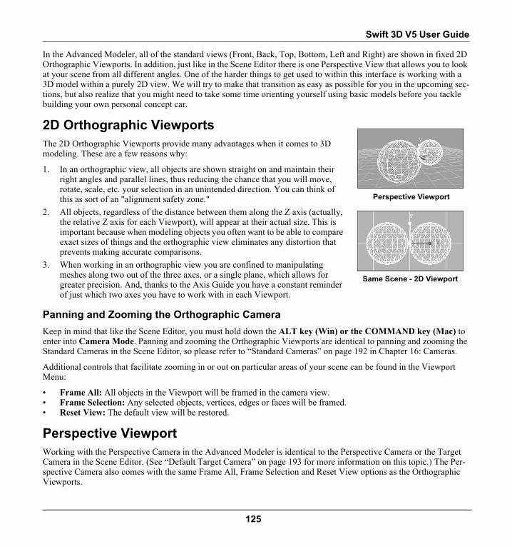
Swift 3D V5 User Guide
In the Advanced Modeler, all of the standard views (Front, Back, Top, Bottom, Left and Right) are shown in fixed 2D Orthographic Viewports. In addition, just like in the Scene Editor there is one Perspective View that allows you to look at your scene from all different angles. One of the harder things to get used to within this interface is working with a 3D model within a purely 2D view. We will try to make that transition as easy as possible for you in the upcoming sec-tions, but also realize that you might need to take some time orienting yourself using basic models before you tackle building your own personal concept car.
2D Orthographic Viewports
The 2D Orthographic Viewports provide many advantages when it comes to 3D modeling. These are a few reasons why:
1. In an orthographic view, all objects are shown straight on and maintain their right angles and parallel lines, thus reducing the chance that you will move, rotate, scale, etc. your selection in an unintended direction. You can think of this as sort of an "alignment safety zone."
2. All objects, regardless of the distance between them along the Z axis (actually, the relative Z axis for each Viewport), will appear at their actual size. This is important because when modeling objects you often want to be able to compare exact sizes of things and the orthographic view eliminates any distortion that prevents making accurate comparisons.
3. When working in an orthographic view you are confined to manipulating meshes along two out of the three axes, or a single plane, which allows for greater precision. And, thanks to the Axis Guide you have a constant reminder of just which two axes you have to work with in each Viewport.
Panning and Zooming the Orthographic CameraKeep in mind that like the Scene Editor, you must hold down the ALT key (Win) or the COMMAND key (Mac) to enter into Camera Mode. Panning and zooming the Orthographic Viewports are identical to panning and zooming the Standard Cameras in the Scene Editor, so please refer to “Standard Cameras” on page 192 in Chapter 16: Cameras.
Additional controls that facilitate zooming in or out on particular areas of your scene can be found in the Viewport Menu:
• Frame All: All objects in the Viewport will be framed in the camera view.• Frame Selection: Any selected objects, vertices, edges or faces will be framed.• Reset View: The default view will be restored.
Perspective ViewportWorking with the Perspective Camera in the Advanced Modeler is identical to the Perspective Camera or the Target Camera in the Scene Editor. (See “Default Target Camera” on page 193 for more information on this topic.) The Per-spective Camera also comes with the same Frame All, Frame Selection and Reset View options as the Orthographic Viewports.
Perspective Viewport
Same Scene - 2D Viewport
125

Chapter 13 | Advanced Modeler
Viewport Display ModesThe graphical display of object meshes in the Advanced Modeler is similar to the Scene Editor. From the Viewport Menu button each Viewport can be set to Texture Smooth Shaded, Smooth Shaded, Flat Shaded or Wireframe, as well as the option to Draw Backfaces. (See “Viewport Display Settings” on page 51 for more information on this topic.)
Objects and their meshes take on different display states during the selection process, which is discussed in the upcom-ing section on Selection. Also, when you are editing a mesh, all other objects in the Viewport will take on a gray stip-pled display, which means they cannot be edited while the Edit Mesh button is enabled.
The Advanced Modeler also comes with these two additional display modes:
Show > Wire Overlay: When the Show Wire Overlay option is turned on, the wireframe of the mesh is shown over the top of the Flat Shaded, Smooth Shaded or Texture Smooth Shaded modes. (Note: Showing the Wire Overlay makes it difficult to see the results of any function that serves to smooth a surface area.)
Show > Materials: Through the Show Materials option you can choose to turn off the display of any materials that have been applied to your models. Note that when this option is turned on, the wireframe will take on the color of the applied materials. Turning off the display of materials can help to enhance Viewport rendering speed.
Edit Mesh ButtonThe Edit Mesh button is located on the right side of the Main Toolbar. When this button is dis-abled (gray), the Advanced Modeler exists in a mode that is similar to the Scene Editor, meaning you can only select the mesh at the object level. As soon as you click on the Edit Mesh button, the button’s state changes to Editing Mesh (red), which allows you to begin editing the mesh of the selected object.
Object ModeWhen the Edit Mesh button is disabled you can only select the mesh at the object level, and you can only select one object at a time. Once the object is selected, either click on the Edit Mesh button to edit that object’s mesh, or make use of any of the various tools in the Advanced Modeler that are accessible at the object level. Throughout this chapter, modeling tools that can only be used while in Editing Mesh mode will be clearly designated. Tools that do not carry this disclaimer can be used as documented, whether you are working at the object or mesh level. Keep in mind that when you are working at the object level of a mesh, if you adjust its position, rotation or scale these values get updated in relation to the scene’s global coordinate system.
A final thing to mention about object mode is that primitive meshes get inserted into the Viewport as separate object meshes when the Edit Mesh button is not depressed. This is crucial to understand if you plan on eventually animating the different parts of a model. More on this will be discussed in the next section on the Editing Mesh mode.
Wire Overlay
Edit Mesh Button States
126

Swift 3D V5 User Guide
Editing Mesh ModeOnce you have an object selected in the Viewport you can begin editing its mesh by clicking on the Edit Mesh button. Keep in mind that Scene Editor objects (Text, Primitives, Extrusions, or Lathes) are converted to an editable mesh as soon as you click on the Edit Mesh button. When this happens, a dialog will appear that warns you of this pending conversion. (A checkbox provides the option to turn off this warning dialog. You can also turn this warning on or off by going to Setup > User Preferences.) This conversion can be undone by performing a File > Undo in the Advanced Modeler. For further information on why this conversion occurs, please see previous section on 3D Terminology 101.
Once in Editing Mesh mode you will notice that all of the mesh selection tools that were previously grayed out on the main toolbar become enabled. These tools will be discussed in detail in the upcoming section on Selection, but for now it is just important to note that through these tools you can begin selecting the vertices, edges, faces and defined surface groups of the mesh.
While in Mesh Editing mode, any changes made to the mesh only take place at the local mesh level. For this reason do not use Mesh Editing mode to orient an object’s mesh in relationship to other objects in the scene. When you select an entire mesh and move, rotate or scale it, those operations are only being calculated in relation to the object’s pivot point. A good way to understand this is to visualize the object as a “container” for its mesh. The container’s position, rotation and scale are all based around the object’s pivot point, which remains stationary in relation to the scene’s glo-bal coordinate system. So if you move an entire mesh and then take a look at the coordinates of that object from its Position property page, the coordinates will remain unchanged because the mesh has simply moved around within the object’s container, the container has not budged. NOTE: If you happen to move an entire mesh in Mesh Editing mode you can always go back to the Scene Editor and use the Reset Pivot Location button, located to the right of the Rotation Trackball, to reset the pivot back to the center of the object, but that is not really the best workflow to follow.
When you create a new mesh by inserting a Primitive into the scene while in Mesh Editing mode, that primitive mesh will get added to the existing mesh as a separate Surface Group. (See “Surface Groups (Editing Mesh Mode Only)” on page 141 for more information on this topic.) So even though the meshes appear to be separate from each other, the meshes actually are contained within a single object (and you can certainly orient those meshes in relation to each other since they both exist within that object “container”). To add a primitive mesh to the scene as a separate object you must turn off Mesh Editing. However, if you know you will never have any reasons to select different parts of a model for animation purposes you can certainly go ahead and work with the primitive meshes to create your entire model in Edit-ing Mesh mode.
Combining and Breaking Apart MeshesYou can use the Combine With Selection or the Break Out Selection features to either combine separate objects into a single mesh or break meshes apart into separate objects.
127

Chapter 13 | Advanced Modeler
Combine With SelectionThe Combine With Selection feature allows you to join separate objects into a single mesh. This function is only available in the Advanced Modeler when the Edit Mesh button is not depressed. There are many benefits to working with a single mesh, including the abil-ity to combine extrusions, lathes and primitives into a single object. After objects are com-bined into a single mesh you can choose to weld them together or simply keep the two meshes apart as separate surface areas.
To combine objects into a single mesh:1. Bring two objects (e.g., an extrusion and a lathe) into the Advanced Modeler.2. In object editing mode, select one of the object's meshes.3. Hover the mouse over the object you wish to combine with that mesh and right click (Win) or CTRL + click (Mac)
on the second object.4. From the context menu that appears, choose the Combine With Selection option.5. Both objects will now exist as a single object, but can still be selected or edited as separate surface groups when
the Edit Mesh button is pushed.
Break Out SelectionThe Break Out Selection feature allows you to take an area of a single mesh and break it out into a separate object. Note that this feature is only available in Editing Mesh mode.
To break out mesh into a separate object:1. Select an object and click on the Edit Mesh button.2. Use one of the Selection tools to select the part of the mesh that you want to break out
into a separate object.3. Right click (Win) or CTRL + click (Mac) on the selected area.4. From the context menu, choose the Break Out Selection option.5. The display of the selected mesh will automatically turn to the gray stippled effect that indicates it can no longer
be edited as part of the selected mesh, since it now exists as a separate object from its original mesh.
Starting with Gallery Models or PrimitivesBefore we go any further, let's talk about the models and primitives that come with Advanced Modeler because you can't perform any modeling heroics until you first have a mesh to work from. The reason why is that you cannot draw a mesh from scratch in the Advanced Modeler, which means you always need to have some sort of building block in the Viewport to begin with. We've already discussed bringing Scene Editor objects into the Advanced Modeler, so let's now look at two other resources, the Model Gallery and Primitive Meshes.
128

Swift 3D V5 User Guide
Model GalleryThe Model Gallery provides you with 3D mod-els to use as is, or as a starting point for your modeling project. As with all of the other galler-ies in Swift 3D, the Model Gallery works on the drag-and-drop premise. Models will always get inserted as separate objects whether you are in Mesh Editing or Object Editing mode, and if they contain hierarchy, their animations and hierarchy will also be maintained.
To insert a model from the model gallery:1. In the Advanced Modeler, select the Model button on the left side of the main Gallery Toolbar to bring up the
Model Gallery. (Note: Models can be accessed from the Scene Editor as well.)2. Go through the tabs and choose a model.3. Click-and-drag the model to any location within any of the Viewports. The model will get inserted at the coordi-
nate from which it was originally saved into the gallery.
The Model Gallery can also be used as a repository for your own models that you create in Swift 3D.
To save a model to the model gallery:1. Models can only be saved to the gallery from the Scene Editor, so click
on the Scene Editor tab to bring the model back into the Scene Editor.2. If the model is not already selected, click on it to select.3. From the File menu, choose "Save Model..." 4. From the Save Model dialog, choose a name and location within the
Model Gallery for your model.5. Click Save.
Editing Models in the GalleryA mesh model added to the Model Gallery can only be edited in the Advanced Modeler workspace. Once a model is placed into the scene it no longer has any connection to the original model stored back in the gallery, so when you finish editing you must go through the steps for saving a model to the gallery. The original version will remain untouched in the gallery. If you do not desire two copies of the model, either overwrite the previous model by using the same name when saving, or simply delete the previous version from the gal-lery.
You can right click (Win) or CTRL + click (Mac) on the palette window surrounding the thumbnails to bring up the Gallery Setup dialog, from which you can delete, rename or relocate any gallery content. For information on how to share Gallery content and managing Galleries in Swift 3D, see the section on Galleries in the Scene Editor chapter.
129

Chapter 13 | Advanced Modeler
Primitive MeshesAs discussed in our earlier section on 3D Terminology, Primitives in the Scene Editor are parent objects that are derived from a mesh. In the Advanced Modeler, this type of parent relationship is not possible, so the primitives made available here are simply meshes based on the primitive shapes that you find in the Scene Editor. As a result, you only have access to each Primitive’s property page before that primitive gets inserted into the Viewport.
Let’s look at it this way. You’ve inserted a sphere-based mesh into the Viewport, and using your impressive, new-found modeling skills have molded that sphere into a dol-phin. That dolphin does not in any way resemble the sphere it spawned from, so you can’t possibly to go back and change any of the sphere’s original properties and expect Swift 3D to have a clue as to what you expect to happen.
Inserting PrimitivesSo, as you have probably guessed, inserting a primitive in the Advanced Modeler will not be the same as that nice, simple click of the mouse that you can use to achieve such greatness in the Scene Editor, but it is not rocket science either. When you click on one of the Primitive buttons in the Advanced Modeler, all you have achieved is opening that primitive’s property page in the Properties Toolbar. This is your key that you must first set the segmentation properties of the primitive, or sim-ply leave the settings at their default values if you so choose. (Refer to Chapter 7: Primitives on page 73 for information regarding the segmentation values of each primitive.)
After adjusting these settings, click and drag out the primitive in the Viewports until you are happy with its size. The primitive's size is automatically kept proportional when dragged out in the Perspective Viewport; however, you must hold down the CTRL key (Win) or OPTION key (Mac) while dragging out the primitive to maintain proportional sizing in the Orthographic Viewports. The Torus and Cone primitives are the exception as they still include some size settings (the top and bottom radius of the cone, and the major and minor radius of the torus), which can’t be adjusted when dragging out these primitives. These settings exist as ratios, however, instead of exact units used by those same primitives in the Scene Editor.
To insert a primitive:1. Set the Editing Mode button to its Mesh Editing or Object Editing state depend-
ing on whether you want to add the mesh to an existing mesh or create a separate mesh object. If you do not have an existing mesh in the scene, the state of this button will not matter.
2. Click on the Primitive button of your choice from the main toolbar.3. The properties specific to that primitive will appear in the Properties Toolbar.
(See the chapter on Primitives for detailed information on all of the properties available to each primitive.)
130

Swift 3D V5 User Guide
4. Make any changes to the default settings. Use the preview window to determine when you have the correct set-tings since once the primitive is inserted you cannot go back and change these settings.
5. In any of the Viewports, click and drag the cursor until the primitive reaches the size you require. In the Ortho-graphic Viewports, hold down CTRL (Win)/OPTION (Mac) to maintain the primitive’s proportions as you size it.
When you drag out a primitive in one of the Orthographic Viewports, the starting position of the primitive will always depend on where it was drawn. Primitives created in the Perspective Viewport will always get inserted around the (0, 0, 0) coordinate.
General PropertiesModeler OptionsThe following two settings are strictly intended to help increase internal rendering performance while working in the Advanced Modeler.
Auto Smoothing - Swift 3D will automatically smooth surface areas of a mesh unless you otherwise define smoothing groups (see the section on Smoothing Groups at the end of this chapter). As you work with a mesh, pushing and pulling various parts, it requires additional internal rendering power for Swift 3D to constantly update the display of surface smoothing. By default, this feature is therefore turned off. Note: If the Show Wire Overlay option is enabled you will not notice any differ-ence to smoothing.
Redraw All Viewports - By default, as you move, rotate, scale, etc. a mesh, that action only takes place in the active Viewport. Once the action is complete, the other Viewports will then update their views as well. However, if you need to see the action take place in all of the Viewports as it is occurs, check the Redraw All View-ports option. Again, by only having the redraw take place in one Viewport at a time, performance is enhanced.
SettingsNudge Increment - This setting controls how far your selected object will move when nudged with the keyboard arrow keys. The default increment is set to .10 units, however this can be designated in the User Preference dialog. Since each grid repre-sents one unit, using the default setting of .10, it will take ten nudges to move an object from one grid line to the next. Holding down the SHIFT key while nudging with the arrow keys will move an object ten times the set nudge increment.
Object Name - This grayed out area shows the name of the object currently selected in the Viewport. This name can only be edited from the Object property page in either the Scene Editor or the Advanced Modeler.
131

Chapter 13 | Advanced Modeler
Statistics - The statistics provided on this page show the total number of vertices, edges, faces and surface groups of the mesh at the object level. So even if just a single vertex of a mesh is selected, these statistics will display the totals for the whole mesh that the vertex is a part of. If you are selecting individual areas of a mesh in Mesh Editing mode and need to see the total number of vertices, edges, and faces in that currently selected area, these statistics are provided in the status bar located along the bottom of the interface. If a mesh is not selected, the status bar shows the total statistics for the entire model currently being edited.
Polygon Limitations - The Advanced Modeler has a limitation of 65,535 total vertices or faces.
SelectionNo, still not to the fun stuff yet, but I can guarantee that unless you master the fine art of selecting vertices, edges, faces and surface groups (and not just any ones, mind you, but the ones you intended to select) you will get extremely frus-trated when you start modeling. So stay focused and we'll get through this fast.
Select ToolsThe selection process in the Advanced Modeler works differently than in the Scene Editor because selection can be done on five levels: vertex, edge, face and surface group. There are separate selection tools for each of these elements that are accessible from the main toolbar or the Select menu.
The following shortcut keystrokes are also available for each Select tool: Select Vertices: V; Soft Select: T; Select Edges: E; Select Faces: F; Select Surface Groups: G; Smoothing Group Selection: P
Mesh SelectionWhen in Editing Mesh mode, you have access to the Select Vertices, Soft Select, Select Edges, Select Faces, Select Surface Groups, and Select Smoothing Groups tools. Each mesh element has a different visual representation in the Viewport when selected. A vertex is always indicated by a square icon; an edge by the straight line that forms the side
Vertex Selection
Soft Selection
Edge Selection
Face Selection
Smoothing Group Selection
Surface Group Selection
132

Swift 3D V5 User Guide
of a triangle, as well as its two end points (vertices); and faces and surface groups by all three edges of the triangle (and shaded interior if the Viewport is set to a shaded display mode).
Whether you are selecting an object or mesh element, one of these Select tools is enabled at all times. (NOTE: The Move, Rotate, Scale or Extrude transform tools can be enabled at the same time as any of the Select tools. If both are enabled, the cursor will move back and forth between a selectable state or transform state depending on what area of the mesh the cursor is over. For example, if the cursor is over a mesh element that is already selected, it will show the Move, Rotate, Scale or Extrude cursor, depending upon which of those tools is also enabled. If the cursor is over an element that is not yet selected, you can continue selecting. See upcoming section on Transform Tools for further information.)
Select CursorSince the Advanced Modeler is very mode oriented, many of the functions come with their own cursor icons in order to serve as a visual reminder of which mode or tool is currently being using. The Select tools are all represented by the default pointer cursor. The Select cursor can also have a plus sign or minus sign next to it that indicates if part of the mesh is being selected or deselected.
Mouseover (Editing Mesh Mode Only)In holding with our goal to make Swift 3D an intuitive experience, we have done our best to make the selection process as easy as possible. The Advanced Modeler therefore comes with a selection feature called Mouseover that highlights the mesh in yellow when you are in Editing Mesh mode. Mouseover shows what would be selected if you decide to click down with the mouse. Note that I emphasize “would be” because the selection that is highlighted in Mouseover cannot take on any applied functions. Once the cursor moves away from a selectable mesh element, that element will no longer remain highlighted.
Multiselect in MouseoverYou can hold down the SHIFT key while moving the cursor to multiselect elements in mouseover so that instead of losing a highlighted area as the cursor moves off of an element the highlight is maintained. Clicking down will then serve to select these elements.
Turning Off MouseoverIn addition to being mesmerizing, the Mouseover selection state is computationally intensive, so if you are trying to acquire as much speed as possible turn off Mouseover from the Selection property page. By default, Mouseover is also
Select Vertices Select Edges Select Faces
133

Chapter 13 | Advanced Modeler
only shown in the active Viewport in order to enhance performance. If you want to see the Mouseover state drawn in each Viewport, check the Redraw All Viewports option on the General property page.
Selecting and DeselectingTo select an area of the mesh or the object that is highlighted in Mouseover, simply click down to “lock” the selection. Note that when you click down a plus sign will appear next to the cursor indicating the mesh is being selected and not deselected. When not in Edit Mesh mode, selected objects will turn blue. When working in Mesh Editing mode, selected surface areas and faces will turn orange, while selected vertices and edges will turn red. (NOTE: The vertex that is selected first will always turn green in order to indicate that it is the vertex used as the reference point for Soft Select, Weld and Flatten, features that will be discussed in upcoming sections of this chapter. The vertex that is selected first is not detected when marquee selection is being used so all vertices selected this way will remain red.)
After a selection is made, you can switch from one selection tool to another and still hold onto the selection, but the selected area will switch to that type of element. For example, if you select some faces and then choose the Select Ver-tices tool, those same polygons will remain selected, but by their vertices instead of faces. If you are switching from vertex or edge selection to face selection, only faces that have three vertices or two edges selected will get selected. You cannot move from vertex, edge, or face selection mode to surface group selection mode and maintain a selected area unless all of the vertices, edges and faces of a surface group are selected.
Deselecting is done by holding down the CTRL key (Win) or OPTION key (Mac) while clicking on selecting elements or drawing a marquee box. Note that as soon as you hold down the CTRL or OPTION keys a minus sign will appear next to the cursor that indicates you can only deselect mesh elements while those keys are depressed.
To select an object, surface, face, edge or vertex:1. Depending on whether you are in Editing Mesh mode or not, choose either the Select Vertices [V], Edges [E],
Faces [F], Surface Groups [G] or Object [O] tool from the main toolbar.2. Move the cursor over the element of the mesh that you want to select.3. When that element becomes selectable it will turn yellow, which is its mouseover state.4. Click to select the element.
To deselect an object, surface, face, edge or vertex:1. Hold down the CTRL key (Win) or OPTION key (Mac) and click back on any selected element to deselect it.
(Note that since the cursor still hovers over that element it will turn back to the yellow mouseover state until the cursor moves away from it.)
2. Click anywhere in the background to deselect all current selections.
Multiple Selection (Editing Mesh Mode Only)When in Object Editing mode you can only select one object at a time; therefore, all of the following multiple selection processes only apply when you are in Editing Mesh mode and selecting surface groups, faces, edges or vertices.
To select multiple surfaces, faces, edges or vertices:1. Choose either the Select Vertices [V], Edges [E], Faces [F] or Surface Groups [G] tool from the main toolbar.
134

Swift 3D V5 User Guide
2. Click on that element in the Viewport, and continue to click on other elements of the same type until you have all the desired elements selected. (Note: You do not have to hold down the SHIFT key to multiple select.)
3. If you make a mistake and need to deselect a selected element, hold down the CTRL key (Win) or OPTION key (Mac) and click back on that element to deselect it. Click in the background to deselect all current selections.
OR,
1. Choose either the Select Vertices [V], Edges [E], Faces [F] or Surface Groups [G] tool from the main toolbar.2. While holding down the SHIFT key, drag the cursor over the elements you want to select (without clicking down).
As the cursor moves, all of the elements it rolls over become held in Mouseover state.3. When you are done highlighting, click down to lock the selection and then let go of the SHIFT key.
Marquee SelectionMarquee selection is the process of clicking down the mouse and dragging a bounding box around areas of the mesh that you wish to select or deselect. Parts of the mesh do not have to be completely within the drawn marquee box to be selected or deselected. Surface groups, faces, edges and vertices will be selected or deselected if the marquee box touches any portion of their structure. Marquee selection also does not detect which mesh element is selected first, which is crucial to the Align To > Surface tool, and plays a role in helping to fine tune the Flatten and Weld commands.
To select multiple surfaces, faces, edges or vertices using a marquee box: Click-and-drag a marquee box around the area of the mesh you wish to select.
To deselect using a marquee box:While holding down the CTRL key (Win) or OPTION key (Mac) click and drag a marquee box around the elements you wish to deselect.
NOTE: Marquee selection will always select or deselect any front facing polygons that are captured within its bound-ing box, not just the polygons closest to the front of the Viewport. For example, if a front facing mesh is located directly behind the mesh you are trying to select, its front facing polygons that are captured within the marquee box will also get selected. If this is not desirable you will need to use one of the other multiple select options offered, such as holding down the SHIFT key while in Mouseover
Additional Selection OptionsFrom the Edit menu you also have access to a few more selection options when in Mesh Editing mode only:
Select All will select all objects in the Viewport. The CTRL + A (Win) or COMMAND + A (Mac) shortcut keys can also be used to perform this function.
Select Inverse allows you to reverse the current selection so that all vertices, edges, faces or surface groups that were not selected become selected, while the current selection becomes deselected. The CTRL + I (Win) or COMMAND + I (Mac) shortcut keys can also be used to perform this function. (This function is only available in Editing Mesh mode.)
135

Chapter 13 | Advanced Modeler
Troubleshooting Selection Problems
Flip NormalsIf you encounter a situation in which you cannot select certain areas of a mesh it is likely that the surface normals are facing in the wrong direction. Use the Transform > Flip Normals feature to reverse the direction of the surface nor-mals. (Note: To select the back facing polygons, either go to the Selection property page and turn off Ignore Back-faces, or select all of the surfaces with outward facing normals first, and then use the Edit > Select Inverse option to select just those surfaces with normals facing inward.)
Orthographic ViewportsWhen working in the Perspective Viewport or any of the camera views in the Scene Editor, if you zoom in too far on an object it is very clear when the camera lens bumps into an object and begins to pass through an object. The same does not hold true for the Orthographic Viewports, so if you are zoomed in on a mesh and find that you cannot select any of its elements, try zooming back out a bit and try again.
Selection Property PageThe Selection property page provides additional features related to the selection process.
Enable MouseoverAlthough Mouseover serves as an extremely helpful selection aid, it also requires more computation time. You can turn off the Mouseover feature from the Selection property page by unchecking the Enable Mouseover option.
Ignore Backfaces (Editing Mesh Mode Only)By default the Ignore Backfaces option is disabled, which means that both front and back facing polygons are available to be selected. If you do not want back facing poly-gons to be selected, turn this feature on. This obviously takes a bit of pressure off of the whole selection process because you do not have to worry about accidentally selecting any elements lurking in the background.
136

Swift 3D V5 User Guide
To select backfaces: 1. From the Viewport Menu choose Draw Backfaces. Note:
You do not have to turn Draw Backfaces on in order to select backfaces. This is just a convenience if you choose to use it, and might not make any difference depending on the angle the object sits in relation to the camera.
2. From the Selection property page, uncheck the Ignore Backfaces option.
3. In the Top View, draw a cylinder of average size.4. Choose the Select Vertices tool.5. In the Top View, click on one of the vertices located on the
front outer edge of the Cylinder. 6. Once the vertices are selected, take a look in either the Left or Front Viewport and notice that all of the vertices
that lay behind that one vertex, and were therefore obscured from view in the Top Viewport, have also been selected.
Enable Multiselect (Editing Mesh Mode Only)The Enable Multiselect option turns on and off the ability to select all front or back facing polygons, whether the poly-gons are in view or not. By default this option is turned off. When Multiselect is turned on, all polygons located behind a selected area (visualize an arrow piercing straight through a mesh and striking any meshes that lie directly behind) will get selected as well. To change this feature to select only front facing polygons, make sure the Ignore Backfaces option is enabled. (Note: Marquee selection ignores the state of Enable Multiselect and will always select front facing polygons that are captured within its bounding box.)
Nick's TipsWhen selecting vertices, edges, faces or surface groups it never hurts to give the Perspective View a spin just
to make sure that you have not inadvertently selected something you had not intended to include. Just ALT (Win) or COMMAND (Mac) click-and-drag in the Perspective Viewport to rotate the camera around the object. If you find an unexpected element did indeed become selected, simply choose the appropriate selection tool and deselect the element. A quick glance at the Orthographic Viewports can be revealing as well.
Soft Select (Editing Mesh Mode Only)(Using Soft Select requires concepts talked about later on in this chapter, so you may just want to give this section a quick read for now and come back to it after you have learned more about transforming objects and manipulating their mesh.)
Soft Select allows you to create what is essentially a magnetic field surrounding a single vertex. As with a magnetic field, the rate at which the intensity or strength of the pull that exists within the field decreases the further away you are from its magnetic source. In the Advanced Modeler, when you use Soft Select to select a single vertex, a range of ver-tices radiating out from this vertex become selected as well, which you can envision as the magnetic field. So when you push, pull, rotate or scale from the original vertex, the degree to which the surrounding vertices are drawn along with that vertex lessens the further away from the original point they are located. This feature is extremely cool because it allows you to quickly create a smoother, more natural looking transformation on the surface of the object.
Vertex Selected in Top View
Front View Showing Back Vertices Selected
Ignore Backfaces = Off
137

Chapter 13 | Advanced Modeler
Entering Soft Select ModeThe Soft Select option can be accessed from the set of Select tools located on the main toolbar, through the Select menu, or by using the shortcut [T]. Once you enter Soft Select mode your first order of business is to choose the center of the magnetic field, which will be a single vertex. Along with that vertex, a default range of vertices sur-rounding that single vertex will become selected as well. As you roll the cursor around the object you will see all of the vertices in the current Soft Select range highlighted in yellow (read next section on Vertex Radius for information on how to adjust the size of this area). The Soft Select area will not become permanently locked until you click on a vertex.
As soon as you click down, the center vertex from which the soft select area is deter-mined will turn green and the rest of the vertices included in the soft select will turn red. At this point in the process, choose either the Move, Rotate or Scale tool to begin manipulating the selected area.
Adjusting Vertex RadiusWithin the Selection property page you have the option to redefine the size of the sur-face area included in your Soft Select by adjusting the Vertex Radius slider. Moving the slider to the left will decrease the area included in the Soft Select, while moving the slider to the right will increase the range. Before the Soft Select area is locked down you can move this slider to its different settings (2 through 10) and as the cursor moves over the mesh you will see the changes in the size of the Soft Select area. Once the Soft Select area is permanently selected you can no longer adjust the Vertex Radius unless you deselect the Soft Select by clicking in the background and going back into Soft Select mode.
If you are not able to refine your selection accurately enough, you may need to create additional faces within the desired Soft Select area so that the Vertex Radius control has more vertices to choose from. This can be done through the Subdivide feature, which is discussed later on in this chapter.
Also keep in mind that the way your mesh is balanced and the direction that edges are turned will have a major impact on which vertices are included in the Soft Select region. See Balance Mesh (under Subdivide) and Turn Edge for details on these using these features.
138

Swift 3D V5 User Guide
Choosing Curve TypeThe next decision to make in the Soft Select process is whether you want the pull or push of the Soft Select field to take on a nice, smooth rounded shape or more of a sharply pointed shape. A smooth curve is achieved by choosing the Parabolic Curve Type, while the Exponential Curve Type results in a sharper curve.
Form FactorThe intensity or falloff of the Curve Type can be controlled through the Form Factor slider. This slider ranges from .01 to 1.00, with .01 representing the gentlest curve and 1.00 the steepest. And if there is any doubt, the graph located above the slider serves as a great way to visualize what type of falloff each value will generate.
To soft select:1. Insert a Sphere primitive mesh into the Viewport.2. Go to the Selection property page and make sure that Enable Mouseover is on.3. Choose the Soft Select [T] tool from the main toolbar.4. Roll the mouse over the sphere to detect the range of vertices that will be included in the Soft Select. 5. Adjust the Vertex Radius slider until the area encompassed by the Soft Select is as desired.6. Click on a vertex to lock the Soft Select range. Note that the cursor will automatically turn into the Move cursor,
but you can switch to the Rotate or Scale tool as well.7. From the Soft Select property page, set the Curve Type to be Parabolic or Exponential.8. Adjust the Form Factor slider to control the intensity of the curve's falloff.9. Use the Move, Rotate or Scale tools to manipulate the selected area.
Edit MenuThese additional selection-related functions can be found under the Edit menu:
Hide/Unhide: Mesh can be hidden from view by either choosing Edit > Hide Selection [CTRL + E], which will hide your current selection, or Edit > Hide All [CTRL + H], which will hide all mesh currently contained within the View-ports. To view a mesh that has been hidden, choose Edit > Unhide All [CTRL + U]. An option also exists on the Sur-face Groups property page for hiding individual surface groups. (See “Surface Groups (Editing Mesh Mode Only)” on page 141 for more information on this topic.) As in the Scene Editor, the Object property page also has an option for hiding entire objects.
Duplicate Selection: In the Advanced Modeler you can only duplicate or delete a mesh or object, so you will not find the traditional cut, copy or paste functions. A duplicate of the selected mesh (faces and surface groups only) or object can be made by going to Edit > Duplicate on the main menu or by right clicking (Win) or CTRL + clicking (Mac) to bring up the object context sensitive menu. You can choose to have the duplicate appear in the same place or adjacent to the original object along the X, Y or Z axis.
Delete Selection: When you choose Edit > Delete Selection, all selected meshes or objects will be deleted. (Note: The exception is that you cannot delete the base object, or the object at the top of the hierarchy in the Advanced Modeler.
Soft Select = Parabolic Soft Select = Exponential
139

Chapter 13 | Advanced Modeler
That object can only be deleted from the Scene Editor.) When in Editing Mesh mode, the mesh must be selected using either the Select Faces or Select Surface Groups tools in order to be deleted. You cannot delete selected vertices or edges.
Undo: Edit > Undo [CTRL + Z (Win) or Command + Z (Mac)] is accessed through the Edit menu or the button on the main toolbar. The Undo stack (list) in the Advanced Modeler is kept separate from the Scene Editor Undo stack; however, once you leave the Advanced Modeler its Undo stack is cleared as soon as an undo-able function is performed in the Scene Editor. (The Scene Editor Undo stack is always maintained no matter which editor you are in.) It is important to understand that a complete copy of your model gets placed into the Undo stack each time the model is altered, which can definitely use up a lot of mem-ory. Once you’ve reached a point where you are sure you no longer need access to the Undo stack you can manually clear it using the Edit > Clear Undo function.
Redo will redo any action you have undone, so it will not become enabled until you first Undo an action. This function is accessed by going to Edit > Redo [CTRL + Y (Win) or Command + Y (Mac)] or clicking the Redo button on the main toolbar.
Undo/RedoButtons
140

Swift 3D V5 User Guide
Surface Groups (Editing Mesh Mode Only)
The polygons or triangular faces that make up a mesh also serve to create the surface area for that model. Polygons can be grouped together with other polygons in order to define a specific surface area. The two primary advantages to forming surface groups are:
1. It allows you to quickly select areas of your model that you will frequently be manipulating as an entire piece.
2. It allows you to apply different materials to different surfaces of your model.
The concept of Surface Groups can easily be understood by considering the box primi-tive. When you insert a box primitive into the Viewport and drag a material onto it, the material gets applied to the entire box mesh. The reason is because all six sides of the box belong to the same surface group. Using the Advanced Modeler's Surface Groups feature you can break down the box so that each side consists of its own surface group. Not only does this make it easier to select the individual sides of the box, but separate materials can now be applied to each side since the they have been made into separate surface groups.
An important concept to understand is that no hierarchy exists between surface groups. Surface groups all exist at the same level and polygons cannot be a part of two different surface groups. In addition, surface groups do not need to consist of groups of contigu-ous polygons. For example, going back to our box, if you want to apply the same mate-rial to the top and bottom of the box, these areas can be incorporated into the same surface group.
To create a surface group:1. Insert a box primitive mesh and click on the Edit Mesh button.2. Using the Select Faces tool, select the two polygons that serve to make up one side
of the box.3. Select Surface Groups from the Properties Toolbar.4. Click on the Group Selection button. Selected areas can also be grouped by right clicking (Win) or CTRL + click-
ing (Mac) on the selection and choosing Group > Selection from the context menu.5. The new surface group will be given the name "Regroup01" by default.
Nick's TipsYou might not realize it, but you have already been introduced to surface groups in the Scene Editor. Extru-
sions and Text objects automatically contain three separate surface groups: face, bevel and edge. Since selection in the Scene Editor can only be performed at the object level, these surface groups are only accessible when applying materi-als. However, when you bring an Extrusion or Text object into the Advanced Modeler you can select each of these sur-face groups separately using the Select Surface Groups tool.
141

Chapter 13 | Advanced Modeler
Surface Groups List BoxThe List Box located at the top of the Surface Groups property page displays the names of the surface groups currently present in the Viewports of the Advanced Modeler. If you have not yet defined any surface groups, the default name for the mesh in the Viewport will appear in the list. For example, when a sphere gets inserted, the default surface group of "Sphere01-All Surfaces" will appear in the list box.
Once a new surface group is defined, the name of that surface group will appear in the list box with the default name of "Regroup01." The polygons defined in the new surface group will be removed from their previous surface group since polygons can only be a part of one surface group at a time.
Naming Surface GroupsSurfaces groups can be given more meaningful names by simply selecting the default name from the list box and typ-ing a new name in the field located just below the list box.
Selecting Surface GroupsOnce a Surface Group is defined, that surface area can now be selected as a whole. Use either of the following two methods to select surface groups:
1. From the Surface Groups property page, click on the name of the Surface Group you wish to select in the list box.2. Click on the Select button. All of the faces in that Surface Group will now become selected in the Viewport
or,
1. Choose the Select Surface Groups tool [G] from the Main Toolbar.2. Click on any of the faces that are a part of the Surface Group you wish to
select.3. All of the faces included in the surface group will become selected.
Group All and Ungroup AllThe Group All and Ungroup All features can only be accessed by right clicking (Win) or CTRL + clicking (Mac) on the mesh to bring up the context sensitive menu.
The Group All command will select the entire mesh and place it into a new group (Regroup0X).
The Ungroup All command will ungroup all surface groups and return them to the first surface group listed in the Sur-face Group list box.
While there is an Ungroup All feature there is no way to ungroup specific surface groups because there is no object level surface group that the polygons can be returned to. Therefore, when you want to remove an existing surface group what you need to do is group those polygons into another surface group.
To delete an existing surface group:1. Select the surface group from the list box and click the Select button so that the polygons included in this surface
group become selected in the Viewport.
142

Swift 3D V5 User Guide
2. From the list box, highlight the surface group you want to group the selected polygons with and click on the Select button again.
3. Click on the Group Selection button. Note that both surface groups get joined into a new surface group so it may be necessary to rename the group.
And Separate SelectionAnd Separate Selection is an advanced use of the Surface Groups feature because not only does it create a surface group, but it separates or cuts that surface group from the mesh. This feature can only be accessed by right clicking (Win) or CTRL + clicking (Mac) on the mesh to bring up the context sensitive menu, and then going to Group > And Separate Selection.
Hide/Show Surface GroupsSurface Groups can be hidden from view using the Hide and Show buttons found in the Surface Groups property page.
To hide/show surface groups:1. Select a surface group from the list box.2. Click on the Hide button located under the list box. Selected areas can also be hidden by going to Edit > Hide
Selection or Edit > Hide All.3. To show (unhide) a hidden surface, select the surface group from the list box.4. Click on the Show button.
All hidden areas can also be shown all at once by going to Edit > Unhide All.
MaterialsFrom the Surface Groups property page you also have access to each group's Material properties. When you select a surface group from the list box, the name of the material applied to that group is displayed and its material appears in the Material Preview Window. Since this area of the Surface Groups property page works identically to the Material property page of the Scene Editor, please refer to “Material Property Page” on page 171 in Chapter 14: Materials.
Transform Tools - Move, Rotate, Scale and ExtrudeThe Transform tools talked about in this section refer to the Move, Rotate, Scale and Extrude commands only since there are a lot of common elements to using these transforms. So instead of repeating this information four times, we are going to cover it all here. Specific information regarding each transform tool will be detailed in the upcoming sec-tions.
Selecting Transform ToolsThe Transform tool buttons, located on the main toolbar, remain disabled until a vertex, edge, face, surface group or object is selected. Once one of the transform tools is selected that function can be performed ONLY when the cursor is over a selected mesh element.
Half a Cylinder Grouped and Separated
143

Chapter 13 | Advanced Modeler
The cursor will turn into one of the transform cursors shown below in order to indicate when that function is available. Since the main state of the cursor is its selection state, if the mouse is not over a selected element the cursor will remain as the normal pointer cursor, allowing you to continue selecting mesh elements. This workflow greatly facilitates the ease of moving back and forth between selecting and moving, rotating, scaling or extruding mesh elements since you can be in both a selection and transform mode at the same time.
In addition to clicking directly on the Transform buttons on the main toolbar, you can also select these tools using the following two methods:
1. By right clicking (Win) or CTRL + clicking (Mac) on a surface and selecting the desired transform tool from the context sensitive menu. Using this method gives you the option to choose different con-straints, such as the X, Y or Z axis. Options available to each trans-form tool are detailed under each tool.
2. Through the Transform menu on the main menu bar, or using the shortcut keystrokes designated in this menu. I highly recommend memorizing the shortcut keys as they will definitely help to facilitate your modeling workflow. The shortcut/hot keys for the transform tools are as follows: Move - M; Rotate - R; Scale - S; Extrude - X.
Transform CursorsOnce any of the Transform tools have been selected, the cursor will change in order to give you a visual representation of when that tool is enabled (i.e., when the cursor is over a selected mesh element).
Since you will often find yourself in a workflow that jumps back and forth between selecting and transforming, these cursor icons are extremely helpful at reminding you which tool is currently selected. With tool in hand, you are now ready to click in any of the Viewports and manually perform that function.
Move Rotate Scale Extrude
144

Swift 3D V5 User Guide
Transform Tool Property PagesWhen you select one of the Transform tools, the property page specific to that transform tool will appear in the Properties Toolbar. The Transform Tool property pages all pro-vide you with the ability to perform that transform in numeric increments, as well as the option to constrain those movements to a particular axis. In addition, any default proper-ties essential to these functions will be contained within these property pages. Details specific to each property page will be discussed in the upcoming sections.
Constraining Transforms in Orthographic ViewportsWhen you use one of the Transform tools in any of the Orthographic Viewports that transform is automatically constrained to just the two visible axes or that single plane. In addition to the constrain features offered by the Axis Guide (See “Axis Guide” on page 124 for more information on this topic.), you can also constrain a transform using any of the following methods:
1. Hold down the SHIFT key while performing the transform. Faint constraining lines will appear as a visual aid.
2. When choosing a transform tool from the context sensitive menu, indicate along which axis you would like the transform to be constrained.
NOTE: Any constraints specific to the Viewport in which you are performing a trans-form will automatically override constraints chosen through the context sensitive menu. For example, if you choose to constrain movement of an object to the Y axis by select-ing Move > Y from the context sensitive menu, if you then try to move the object in the Top or Bottom viewport, which is automatically constrained to just the X and Z axes, you will not be able to move the object along the Y axis. The exception to this rule is rotating, which can be performed around any axis in any Viewport.
Constraining Transforms in the Perspective ViewportIn the Perspective Viewport a transform can be performed along the plane of the camera’s current rotation. As you rotate the camera around, that plane will change. Unlike the Scene Editor Viewports, however, objects cannot be moved towards the camera or away from the camera, which means you cannot Move along the axis that is pointing per-pendicular to the camera. If the axis pointing towards or away from the camera is the axis along which you need to per-form a transform, you must rotate the Perspective view so that you can transform either up or down, or left or right along that axis. To constrain the transform to just one or two of the axes use any of the methods outlined previously for the Orthographic Viewports.
MoveObjects and meshes can only be moved by selecting the Move tool. This differs from the Scene Editor where you can just click and drag on any object. Remember that when you are Editing Mesh mode, if you move an entire mesh that movement occurs in relation to the object’s pivot point only and not the global coordinate system.
145

Chapter 13 | Advanced Modeler
Move ToolThe most common and quickest way to move a selection is by choosing the Move tool and dragging the selected mesh to a new location directly within the Viewport. By default, the Move tool is set to Free until you choose a constraining axis or axes.
Note that once the Move tool is selected it only becomes enabled when the cursor is over a selected mesh element.
To move a selection manually:1. Select the object, surface groups, faces, edges or vertices that you want to move.2. Select the Move tool [M] from either the main toolbar or the context sensitive menu.3. The cursor will change into the Move cursor.4. Set any axis constrains if necessary.5. Click in any of the Viewports and drag the selected area to a new location.
The keyboard arrow keys can also be used to nudge a selection left or right, or up or down.
Move Tool Property Page As soon as the Move tool is selected, the Move property page will become visible in the Properties Toolbar. The precise positioning of selected meshes along the X, Y and Z axes can be achieved from the Move property page.
Note that the values entered on this page represent the amount of movement to be per-formed along that particular axis; they do not represent the numeric coordinate that the object will be relocated to. The world coordinates of an object’s mesh can only be accessed through the Position property page. You can compare it to entering a nudge increment and then having your mesh nudged in that direction by the number of units entered. Every time you click the Move button the object will move the distance entered.
As you would expect, a positive number will move the selection to the right along the X axis, upward along the Y axis and forward along the Z axis. A negative number will move the selection in the opposite direction along those axes.
To move a selection numerically along the X, Y or Z axis:1. Select either vertices, edges, faces, surface groups or object.2. Choose the Move tool [M] from the main toolbar.3. From the Move Tool property page, input a number into any of the numeric input
boxes.4. Click on the Move button.
The X, Y or Z buttons located below each numeric entry fields can be enabled or disabled to constrain movement along any particular axis. By default, the buttons are all turned off, which means movement can occur along all of the axes. Obviously if you only have a value entered in the X box, your object will only move along the X axis, so these buttons only come into play if you need to make precise adjustments. For example, if you want to move a mesh 5 steps along
146

Swift 3D V5 User Guide
the Y axis and 2 steps along the Z axis, and repeat that process several times, you can enter the numbers at the start and then switch back from constraining movement to just the Y and then just the Z without having to re-enter the numbers each time.
The Clear button exists only to reset the numeric entry fields back to zero; this button does not reset the position of the mesh.
Rotate"Wait, there's no trackball? How can I possibly rotate an object without a trackball?" Now, now, calm down (and did I hear a sigh of relief from all of those trackball detractors?), I promise it will be OK. While there is no trackball in the Advanced Modeler, there is a built-in virtual trackball that allows you to rotate your object directly in the Viewport using the Rotate tool. When you are Editing Mesh mode, if you rotate an entire mesh that rotation occurs in relation to the center of rotation (the yellow dot) set in the Rotate Tool Property page, not the object’s pivot point (although the two may correspond.)
Rotate ToolWhen the Rotate tool is selected from the main toolbar its default state is set to Free until you choose a constraining axis or axes.
Note that once the Rotate tool is selected it only becomes enabled when the cursor is over a selected mesh element.
To rotate a selection manually:1. Select the object, surface groups, faces, edges or vertices that you want to rotate.2. Choose the Rotate tool [R] from either the main toolbar or context sensitive menu.3. The cursor will change into the Rotate cursor.4. Click in any of the Viewports and drag the cursor in the direction you want the selection to rotate.
147

Chapter 13 | Advanced Modeler
Rotate Property PageThe Rotate property page can only be accessed by first selecting the Rotate tool.
Rotation CenterUse these options to specify the point around which you want the rotation to occur. The point of rotation is designated by the yellow dot icon that appears when you click down in the Viewport with the Rotate tool. Note: When in Editing Mesh mode, this rotation point is local to the selected mesh.
• Center of Selection: This option, the default and most commonly used, will rotate the selected area around its center. When working at the object level, the Center of Selection corresponds to the object's pivot point, which may or may not reside in the center of the object anymore.
• Origin: This option makes the selected area rotate around the center of the scene at (0, 0, 0).
• Specific Point: This final option allows you to set the exact point around which the selected area will rotate.
To set a the specific rotation point:1. Choose the Rotate tool [R] from the main toolbar.2. Select the Specific Point option from the Rotate Tool property page.3. Enter the coordinates along the X, Y or Z axis to set the rotation point. Click down
with the Rotate tool in any of the Viewports if you need a visual of where the rota-tion point is located while adjusting its X, Y or Z location.
Rotation AnglesPrecise angle of rotations can be achieved from the Rotate Tool property page. As with the Move Tool property page, you are entering an increment of rotation, so every time you hit the Rotate button, the selection will continue to rotate by the degree entered. For example, if you enter 25, to rotate by 25 degrees, and click on the Rotate button, then decide you want to actually rotate it by 28 degrees, you must Undo the 25 degree rotation and then enter 28, or enter 3 to get those 3 extra degrees. Keep in mind that positive numbers will rotate an object to the plus side of an axis and negative numbers will rotate an object towards the negative side of the axis.
To rotate a selection numerically:1. Select the object, surface groups, faces, edges or vertices that you want to rotate.2. Choose the Rotate tool [R] from the main toolbar.3. From the Rotate Tool property page, enter the degree of rotation into any of the X, Y or Z entry boxes, depending
upon which axis you want the rotation to occur.4. Click the Rotate button.
The Clear button exists only to reset the numeric entry fields back to zero; this button does not reset the rotation of the selected mesh.
148

Swift 3D V5 User Guide
ScaleYou can scale vertices, edges, faces, surface groups or objects. Scale can be performed freely (along any axis), uni-formly (the scale is applied equally to all dimensions of the selected mesh), or constrained to the X, Y or Z axis.
Scale ToolWhen you select the Scale tool from the main toolbar, its default state is Uniform Scaling until you choose a constraining axis or axes. Note that once the Scale tool is selected it only becomes enabled when the cursor is over a selected mesh element.
To scale a selection manually:1. Select the object, surface groups, faces, edges or vertices that you want to scale.2. Select the Scale tool [S] from either the main toolbar or context sensitive menu.3. The cursor will change into the Scale cursor.4. Click in any of the Viewports and drag the cursor away from the object to increase its scale and
towards the center of the object to decrease its scale.
Scale Tool Property PageThe Scale Tool property page can only be accessed by first selecting the Scale tool.
Scale CenterUse these options to specify the point from which you want the scale to occur. The point of scale is designated by the yellow dot that appears when you click down in the View-port with the Scale tool. Note: When in Mesh Editing mode, this scale point is local to the selected mesh only.
1. Center of Selection: This option, the default, will scale the selected area out or in from its center. When working at the object level, the center of the selection will always correspond to the location of the object’s pivot point, which might not nec-essarily be located at the object’s center anymore.
2. Origin: This option causes the selected area to scale from the center of the scene at (0, 0, 0).
3. Specific Point: Allows you to set the exact point from which the scale will occur.
To set the specific scale point:1. Choose the Scale tool [S] from the main toolbar.2. Select the Specific Point option from the Scale Tool property page.3. Enter the coordinates along the X, Y or Z axis where you want the center of the
Scale to occur from. Click down with the Scale tool in any of the Viewports if you need a visual of where the scale point is located while adjusting its X, Y or Z loca-tion.
149

Chapter 13 | Advanced Modeler
Scale AmountWhen a mesh enters the scene it automatically has a scale of 1.0, so the numeric input boxes in the Scale Tool property page all have a default value of 1.0, meaning this is the original scale of the mesh. To reduce the mesh by half of its original scale enter 0.5, while 2.0 would represent double the original scale. If you scale anything by zero the object with disappear because multiplying anything by zero results in zero, and obviously negative numbers are not allowed. It is important to remember that as soon as a mesh is scaled, the value 1.0 gets reset to that new scale. Therefore, the next time you click on the Scale button the mesh will Scale numerically based on its current scale, not its original start-ing scale.
To scale a selection numerically:1. Select the object, surface groups, faces, edges or vertices that you want to scale.2. Choose the Scale tool [S] from the main toolbar.3. From the Scale Tool property page, enter the amount of scale that you want into either the X, Y or Z input boxes,
depending upon which axis you want the scale to occur along. To achieve a uniform scale you must enter the same amount in each box.
4. Click the Scale button.
The Clear button exists only to reset the numeric entry fields back to zero; this button does not reset the scale of the mesh back to its original starting point.
Extrude (Editing Mesh Mode Only)
If you have made it this far with Swift 3D you probably reached the understanding that the term "extrude" means to take a 2D object and increase its depth. In the Advanced Modeler, however, you are starting off with objects that are already 3D so extrude takes on a slightly different meaning. Using the Extrude feature you can select faces of the mesh and extrude those faces outward or inward. What happens is that a new set of faces are formed that connect the original faces back to the mesh those faces were extended from.
You can choose to extrude those faces freely (without any constraints), along the X, Y or Z axis, or along the direction the faces are pointing, which is the normal. Note that we are talking about faces only here; you cannot extrude vertices or edges, so in order for the Extrude function to work you must start with at least one selected face.
Faces Extruded OUTBox with Faces Selected Faces Extruded IN
150

Swift 3D V5 User Guide
Extrude ToolBefore you grab the Extrude tool and start pulling faces away from your objects, one important detail must be noted. Once you release the mouse click to finish the extrude, you have completed the formation of a new set of polygons. If you did not extrude the faces out or in far enough, you must employ the aid of the Move tool to move the faces to the correct location. If you try to move the faces further outward or inward by clicking down again with the Extrude tool still enabled you will precede to extrude another set of faces, which may not be your intention.
When you select the Extrude tool from the main toolbar, its default state is to extrude along the normals. Set the axis constraints or choose Extrude from the context sensitive menu to select a different option. Note that once the Scale tool is selected it only becomes enabled when the cursor is over a selected mesh element.
To extrude faces manually:1. Select the faces or surface groups to be extruded.2. Select the Extrude tool [E] from the main toolbar or context sensitive menu.3. The cursor will change into the Extrude cursor.4. Click-and-drag the cursor away from the mesh to extrude the faces outward or in toward the center
of the mesh to extrude the faces inward.
NOTE: The new set of faces formed automatically get placed into a separate surface group. If you prefer to maintain one surface group, go to the Surface Group property page (See “Surface Groups (Editing Mesh Mode Only)” on page 141 for more information on this topic.) and regroup the surface areas back into a single group. .
Extrude Tool Property PageWith Move, Rotate and Scale we talked about how these numeric operations are one shot deals, and the same goes for the Extrude Tool property page. With Extrude this takes on even further meaning because if you click the Extrude button for a second time you will be adding a new set of faces. So if you extrude once, and don't like the location where the faces ended up, you must move them to the desired location or undo the oper-ation and try again.
To extrude numerically along the X, Y or Z axes or Normal:1. Select the faces or surface groups to be extruded.2. Select the Extrude tool [E] from the main toolbar.3. From the Extrude Tool property page, choose the Normal or Direction option.4. Type a number into any of the numeric entry boxes.5. Click Extrude.
The Clear button exists only to reset the numeric entry fields back to zero; this button does not reset the mesh back to its original starting point.
151

Chapter 13 | Advanced Modeler
Align ToThe Align To function allows you to align selected surfaces to either an axis or another surface area. Align To is acces-sible from the Position menu or by right clicking (Win) or CTRL + clicking (Mac) on a surface area to bring up the context sensitive menu.
Align To AxisThe Align To > Axis feature aligns the center of the selection to either the X, Y or Z axis.
Align To Surface (Editing Mesh Mode Only)The Align To > Surface feature can be used with Surface Groups only. The surface to which other surfaces are being aligned to is referred to as the target surface. You have the option of aligning other surfaces to a target surface’s X, Y or Z position. You will always be aligning the center of a surface to where the center of the target surface lies along the X, Y or Z axis.
To align surfaces:1. Begin by selecting the target surface, which will serve as the alignment point
for other objects.2. Continue the selection process by selecting the surface(s) that you want to have
aligned to the target surface.3. Go to Align To > Surface from either the main menu or by right clicking
(Win) or CTRL + clicking (Mac) on a surface to bring up the context menu.4. Select to align the center of the selected surfaces to target surface’s X, Y or Z
center.
Mirror(IMPORTANT: The Mirror function will automatically convert to mesh Extrusions, Lathes, Primitives or Text that have been brought into the Advanced Modeler from the Scene Editor. If you want to hold onto their object properties, use Negative Scaling in the Scene Editor to mirror the object.)
As the name suggests, the Mirror function provides a the mirror image of the selected surfaces or object. Mirror can be performed in three different ways: mir-rored along an axis, duplicated and mirrored along an axis, and duplicated so that the mirrored object’s edge vertices align. The first two features will mirror the mesh in the opposite direction along an axis and maintains the location of the mesh in relation to that axis. So if the center of a mesh is located at X = 5, it mirror image will appear at X = -5 when mirrored along the X axis.
Before Align To Surface
Align To > Surface > Z Axis
Object Mirrored Along X
152

Swift 3D V5 User Guide
The final mirror feature, which is referred to as Mirror > Align Duplicate, is designed to facilitate the process of modeling one side of a model and then mirroring that side with the intention of welding the two sides together. (This mirror option is only available in Editing Mesh mode.) It works by abutting the side around which the mirror is performed and lining up the vertices. The Align > Duplicate has six mirroring options:
• Front to Back and Back to Front: Mirrors the object currently selected along the z axis.
• Left to Right and Right to Left: Mirrors the object currently selected along the x axis.
• Top/Bottom and Bottom to Top: Mirrors the object currently selected along the y axis.
To mirror:1. Select the surface that you want to mirror.2. Select Transform > Mirror from the main menu or by right clicking (Win) or CTRL + clicking (Mac) on a sur-
face to bring up the context sensitive menu. 3. Select either the Axis, Axis Duplicate or Align Duplicate option and choose the axis or direction along which you
want the mirror to occur.4. A mirrored duplicate of the object will appear along the axis you selected.
When modeling a single side of an object with the intention of mirroring and then joining the two sides together, verti-ces can be quickly joined by using the SmartWeld function that is detailed in an upcoming section.
FlattenFlatten is somewhat of a dual purpose tool. Its primary purpose is to flat-ten the selected mesh to either the X, Y or Z axis. However, when used on selected vertices, Flatten will align those vertices into a single row along the X, Y or Z axis. When aligning vertices, the alignment is based on the first vertex that is selected, which is indicated by its green selection state (as opposed to the normal red selection state). Note that marquee selection does not detect which mesh element is selected first, so if you use this method to select multiple vertices to flatten, the vertices will flatten to an average location.
While this feature is accessible when working at the object level, really all it can do is take the entire mesh and flatten it like a pancake.
Half a Mesh MirroredFront to Back
Selected Vertices Vertices Flat-tened to Z Axis
153

Chapter 13 | Advanced Modeler
To flatten:1. Select the surface area that you wish to flatten.2. Choose Transform > Flatten from either the main menu or by right
clicking (Win) or CTRL + clicking (Mac) on a surface to bring up the context menu.
3. Choose whether you want the surfaces to flatten the X, Y or Z axes.
RoundnessRoundness is the process whereby selected polygons are rounded outward (increased) or inward (decreased) by mov-ing the vertices of the selected area out or in from a central point. In order for Roundness to have any noticeable affect on a selected area, the function requires a fair amount of vertices and surfaces to work on. For example, if a box with just two faces per side is inserted into the Viewport, when Roundness is applied to that box you will see no discernible difference. However, if you subdivide the box’s faces a couple of times and then apply this feature, the box will begin to round outward or inward.
There is no exact science to using this feature so you can’t just look at your object or set of faces and determine exactly what the results will be when you round. It is the type of feature that you apply once, and if you are happy with the results, great, but if you want more or less roundness you give it another shot. Or, if you do not receive the results you need, you might try subdividing the faces an additional time and then trying the Roundness operation again. Some-times modeling is all about a little experimentation.
To round:1. Insert a Cylinder primitive into the scene.2. Choose Transform > Roundness from either the main menu or by right clicking (Win) or CTRL + clicking
(Mac) on a surface to bring up the context menu.3. Choose Roundness > Increase to push the surface area of the cylinder outward.4. Choose Roundness > Decrease to pull the surface area of the cylinder inward.
Selected Faces Faces Flattened to Z Axis
Subdivided Box Increased Roundness Decreased Roundness
154
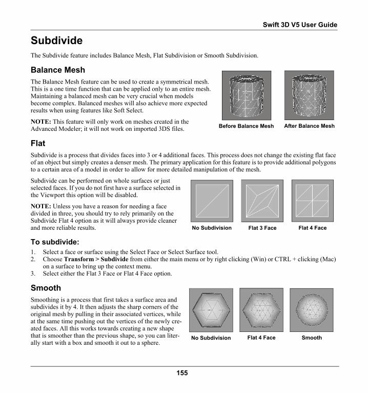
Swift 3D V5 User Guide
SubdivideThe Subdivide feature includes Balance Mesh, Flat Subdivision or Smooth Subdivision.
Balance MeshThe Balance Mesh feature can be used to create a symmetrical mesh. This is a one time function that can be applied only to an entire mesh. Maintaining a balanced mesh can be very crucial when models become complex. Balanced meshes will also achieve more expected results when using features like Soft Select.
NOTE: This feature will only work on meshes created in the Advanced Modeler; it will not work on imported 3DS files.
FlatSubdivide is a process that divides faces into 3 or 4 additional faces. This process does not change the existing flat face of an object but simply creates a denser mesh. The primary application for this feature is to provide additional polygons to a certain area of a model in order to allow for more detailed manipulation of the mesh.
Subdivide can be performed on whole surfaces or just selected faces. If you do not first have a surface selected in the Viewport this option will be disabled.
NOTE: Unless you have a reason for needing a face divided in three, you should try to rely primarily on the Subdivide Flat 4 option as it will always provide cleaner and more reliable results.
To subdivide:1. Select a face or surface using the Select Face or Select Surface tool.2. Choose Transform > Subdivide from either the main menu or by right clicking (Win) or CTRL + clicking (Mac)
on a surface to bring up the context menu.3. Select either the Flat 3 Face or Flat 4 Face option.
SmoothSmoothing is a process that first takes a surface area and subdivides it by 4. It then adjusts the sharp corners of the original mesh by pulling in their associated vertices, while at the same time pushing out the vertices of the newly cre-ated faces. All this works towards creating a new shape that is smoother than the previous shape, so you can liter-ally start with a box and smooth it out to a sphere.
Before Balance Mesh After Balance Mesh
No Subdivision Flat 3 Face Flat 4 Face
No Subdivision Flat 4 Face Smooth
155

Chapter 13 | Advanced Modeler
There are two options for Smoothing: Subdivide Smooth Exclude Border and Subdivide Smooth Include Border. When smoothing an object that is a closed shape, meaning it has no exposed borders, it does not matter which of these options you choose as they will both provide the same results. These two options come into play when you are smoothing a shape that has borders. The Exclude Border option will maintain the integrity of that out-side edge so that it is not taken into consideration during the smoothing pro-cess. The Include Border option will take into account the border when it calculates smoothing. While the Include Border option will result in a perfect subdivision, and therefore the smoothest surface possible, it produces undesirable results on outside edges by pulling them in, which gives a very jagged appear-ance to that outside edge.
Delete Empty FacesAs you work with your model performing numerous subdivisions, empty faces get created that allow you to pull newly subdivided faces, edges and vertices away from existing meshes without creating holes in the mesh. While these poly-gons are necessary to prevent holes from occurring in the mesh, it can lead to empty faces that are not being used and are therefore adding unwanted size to your mesh. These empty polygons can be deleted by going to Transform > Delete Empty Faces. While subdividing is the most common way to create empty polygons, other actions, such as clicking on the Extrude tool and not moving them out, will also lead to empty polygons.
Edge (Editing Mesh Mode Only)
The Divide Edge and Turn Edge features allow you to manipulate the mesh of your model in several distinct ways.
Divide EdgeThe Divide Edge function works by dividing the faces that the edge has in common into two additional faces. While the Divide Edge function can be applied to multiple edges at a time, it is recommended that you do not select edges that share the same face. For example, if you have two edges of one face selected, once the program divides the first edge a new set of edges now exist that will determine how the second edge will get divided, and so forth. As you can imagine, it becomes virtually impossible to predict what type of results will occur.
To divide an edge:1. Use the Select Edges tool to select an edge or multiple edges.2. Choose Transform > Edge > Divide Edge from either the main
menu or by right clicking (Win) or CTRL + clicking (Mac) on a sur-face to bring up the context menu.
Turn EdgeThe Turn Edge feature allows you to change the direction of an edge to the opposing vertices of its two adjoining faces. (This function can only be applied to one edge at a time.) Depending on whether those two adjoining faces exist on the same plane, the Turn Edge
Exclude Borders Include Borders
Divide Edge AfterDivide Edge Before(4 Edges Selected)
156

Swift 3D V5 User Guide
function may or may not affect the outward appearance of the model. In the first set of screen shots below, notice that the Turn Edge operation was performed on an edge that separates two faces that exist on the same plane. What this operation did was simply change the direction of the common edge these faces share. In the next example, since the selected edge adjoins faces that exist on different sides of the box, the Turn Edge operation actually resulted in a notch-ing out the surface.
The ability to notch out a surface has obvious advantages, but a beginning modeler might be inclined to overlook the more advanced uses of this fea-ture when it comes to the maintaining the symmetry of a mesh. While a cleaner mesh will always be easier to work with as a model progresses in complexity, it is important to realize that an unbalanced mesh will not maintain its symmetry when advanced functions like smoothing are applied to it. In addition, depending on the rendering option you choose, an untidy mesh might provide undesirable rendering results. Again, this is fairly advanced stuff, and when working with simple models it might not even matter. But if you plan to take your modeling to a higher level this type of attention to the structure of your mesh eventually needs to be taken into consideration.
Turn Edge ToolThe Turn Edge tool simplifies the process to a single click. To activate the Turn Edge Tool, Edge Selection must be active and the Turn Edge Mode button, located in the top toolbar, toggled on. Once active, you only need to click on an edge to turn it.
To turn an edge using the Turn Edge Tool:1. Click the Select Edge tool.2. Toggle on the Turn Edge Mode button.3. Click on the edge you wish to turn.
OR,
1. Use the Select Edge tool to select an edge.2. Choose Transform > Edge > Turn Edge from either the main menu or by right clicking (Win) or CTRL + click-
ing (Mac) on a surface to bring up the context menu.
Planar Edge Selected Turn Edge After
Corner Edge Selected Turn Edge After
157

Chapter 13 | Advanced Modeler
Weld (Editing Mesh Mode Only)
Performing the Weld command on two or more selected verti-ces will collapse those vertices into a single vertex. If you click to select the vertices to be welded together, the first vertex selected will serve as the alignment point for the rest of the ver-tices. An average of all vertices can be obtained by marquee selecting the vertices to be included in the weld since marquee selection does not detect which is the first vertex to be chosen.
To weld vertices:1. Select two or more vertices using the Select Vertices tool.2. Choose Transform > Weld [W]from either the main
menu or by right clicking (Win) or CTRL + clicking (Mac) on a surface to bring up the context menu.
3. The selected vertices will now be merged into a single vertex.
SmartWeldWelding vertices can be a tedious process if you have more than one set of vertices that need to be joined. This process can be greatly simplified by employing the SmartWeld feature. When SmartWeld is used, any vertices that are currently selected look to see if there are any vertices nearby (within a given tolerance) that are also selected, and if so they join and merge. Let the co-mingling begin.
To smartweld vertices:1. Select a group of vertices.2. Choose SmartWeld from either the main menu or by
right clicking (Win) or CTRL + clicking (Mac) on a surface to bring up the context menu.3. Any vertices that lie within a certain range of each other will be joined.
SmartWeld Tolerance SliderYou can set the tolerance level for the detection of available vertices using the Smart-Weld Tolerance slider located on the Selection property page. As this setting increases, SmartWeld will weld selected vertices located across a greater range into a single vertex, therefore making this operation less accurate, or more encompassing.
Vertices selected on half of a sphere
Vertices collapsed to a single vertex
Selected vertices of two unjoined objects
Vertices joined using SmartWeld
158

Swift 3D V5 User Guide
Nick's Tips
When welding vertices that are located close together it is often difficult to deter-mine if anything actually happened. I recommend that when you select vertices to be welded, always check the status bar to make sure the correct number of vertices are selected to begin with. After the Weld or SmartWeld function is performed, recheck the number of vertices to make sure it has been reduced by the proper amount.
Smoothing Groups (Editing Mesh Mode Only)
If you recall from our discussion of 3D terminology, the face of a polygon is planar (a.k.a. flat). However, you may have noticed that when you create something with a curved surface area, like a sphere, it is displayed in the Viewport (and rendered) as one continuous, smooth surface instead of a series of segmented, flat surfaces.
The reason is because surfaces are automatically smoothed, which works by removing the hard edges in between sur-faces, blending them to produce one smooth surface.
NOTE: In order to see the changes made to the surface of your model you must have your Viewport Display Mode set to Smooth Shading and have the Show Wire Overlay option turned off.
Assigning Smoothing GroupsIn the Advanced Modeler, you can assign Smoothing Groups to different surface areas in order to define where you want Swift 3D to place hard edges. (Surface areas can be assigned multiple smoothing groups.) Smoothing groups are simply numbers ranging from 1 to 32, although in reality you have access to far more than 32 Smoothing Groups since the numbers can be assigned to more than one surface. As long as surfaces do not share an edge, smoothing group number assignments can be reused as many times as you want.
Unsmoothed Smoothed Smoothing Group Assigned
159

Chapter 13 | Advanced Modeler
Now, if you are like me and can't remember what you ate for breakfast, you might be staring at those 32 numbers wondering how you can possibly keep track of groups that are solely defined by numbers. Keep in mind that the purpose of Smoothing Groups is primarily to place a hard edge in between two adjacent surfaces. It does not matter if the two surface areas are assigned Smoothing Group numbers 1 and 2 or 7 and 16; it only matters that the numbers are different. So sometimes you can get away with simply alternating between two Smoothing Group numbers, while other times, depending on your goals, you might have reasons to keep each Smoothing Group in their own separate numbers. Really, the key is that if you think you might need to change the smoothing properties of a particular surface area, then keep that surface area to its own Smoothing Group number.
To assign a smoothing group:1. In Editing Mesh mode, insert a sphere into the Top Viewport.2. From the Selection property page, turn off Ignore Backfaces.3. Using the Select Faces tool, in the Right Viewport draw a marquee box to select the
entire right side of the sphere.4. Select Smoothing Groups from the Properties Toolbar.5. Click on Assign to enable the Smoothing Group number grid.6. Click on number 2 to assign the right side of the sphere to Smoothing Group 2.7. In the Perspective Viewport, change the display mode to Smooth Shaded, making sure to turn the Show Wire
Overlay option off as well. Notice that there now exists an edge, which is shown by a clear difference in the shad-ing, between the two halves of the sphere.
Selecting Smoothing GroupsWhen your model begins to get complicated, the potential to lose track of just which surface areas have been assigned to which Smoothing Groups can definitely start to occur. Fortunately, the Smoothing Group number grid has two states to it, Select and Assign. As the name indicates, when the Select button is chosen you can click on a number and the surface areas associated with that Smoothing Group number will all become selected in the Viewport. Notice also that only those numbers that have been assigned to surfaces are enabled in Select, so this is also a great indicator of which Smoothing Group numbers are still available for use.
You can also go about detecting Smoothing Group assignments from the mesh itself. If you hover over different parts of the mesh in the Viewport with either the Select Faces or Select Surface Groups tools (make sure Mouseover is enabled on the Selec-tion property page), you can see the Smoothing Group assignment for each surface because that number will temporarily become depressed. If you actually click down to select a surface, the depressed state of that number will lock until that surface area becomes deselected again.
To select smoothing groups:1. Start with the sphere created in our previous steps on assigning a Smoothing Group.
160

Swift 3D V5 User Guide
2. From the Smoothing Group property page, click on the Select button. When Smoothing Groups are assigned those numbers become enabled, so in the case of our sphere Smoothing Groups 1 and 2 should be enabled.
3. Click on Smoothing Group 1 in order to select that surface area. 4. Click back on Smoothing Group 1 in order to deselect that surface area.5. Next, deselect any surfaces that may be selected and then choose the Select Faces tool.6. Go to the Perspective Viewport and hover the mouse over any of the faces included in Smoothing Group 1. Notice
how Smoothing Group 1 becomes depressed in the Properties toolbar, which is a great way to quickly ascertain smoothing group assignments.
Clearing Smoothing GroupsSince surfaces can be assigned multiple smoothing groups, the only way to clear a smoothing group is to deselect the Smoothing Group number(s) assigned to a particular surface area.
To clear a smoothing group:1. Select the surface area that you wish to clear of its smoothing groups.2. Go to the Smoothing Groups property page and click the Assign button.3. Click on any of the Smoothing Group numbers assigned to that surface area to clear those numbers. (Note: This
only clears that Smoothing Group number for the selected surface area. It does not clear this smoothing group for any other surface areas that might be assigned to this number.)
Unsmoothing SurfacesUp until now we have been working on the assumption that we actually want our Smoothing Groups to be nicely smoothed. Using the Unsmooth Selection or Unsmooth All buttons you can create hard edges between every single polygon in your model. Unsmooth Selection will unsmooth just the currently selected faces, while Unsmooth All will unsmooth everything in the Viewport, whether selected or not.
Once a surface area is unsmoothed, it is no longer associated with any smoothing groups. Unsmoothed portions of a mesh can be selected by clicking on the Select All Unsmoothed button.
If you want to resmooth an unsmoothed surface, simply reassign that surface to a Smoothing Group.
161

Chapter 13 | Advanced Modeler
Using Smoothing Groups to Control Rendered OutlinesProbably one of the coolest features that comes along with Smoothing Groups is the ability to control exactly where outlines get rendered. For example, in the screen shots shown to the right, you can see that different Smoothing Groups have been assigned to each horizontal slice of the cylinder. Upon rendering to Outlines using RAViX, the hard edge is detected between each of these slices, which allows you to customize where outlines get rendered. For more information on rendering to Outlines, see the chapter on Rendering With RAViX.
Mesh Morpher (Editing Mesh Mode Only)
The Mesh Morpher provides you with the ability to animate the vertices of a solid mesh, so any mesh deformation you can subject your models to can now be put into motion. Not seeing a timeline in the Advanced Modeler you say? Working in conjunction with the Scene Editor is how animation is achieved and more information can be found in Chapter 17: Animation on page 214. However, before you can get to the point of animat-ing, you need to first setup the basis for your animation within the Advanced Modeler. This is accomplished by creating Morph Groups and Morph Targets within the Mor-pher properties page.
Morph GroupsA Morph Group can consist of a selected portion of an object’s mesh, a complete mesh object or multiple mesh objects.
To create a Morph Group:1. Create a Mesh in the Advanced Modeler or bring in an object from the Scene Editor
and enable Mesh Editing.2. Select a portion of the Mesh’s vertices.3. Click the Create Group button in the Morpher properties page.
The new Morph Group will be automatically assigned a name, such as “Morph Group 01,” however this can be changed in the Morpher properties page. If you plan to have a large number of groups it is a good idea to give them unique names in order to make working with them easier when animating in the Scene Editor. A scene can contain an unlimited number of Morph Groups.
Smoothing Groups Assigned to Each Slice
Cylinder Rendered to Outlines
162

Swift 3D V5 User Guide
To delete a Morph Group:1. Select the group’s name from list of Morph Groups.2. Click the Delete Group button. (Note that deleting a Morph Group does not delete the object from the viewport,
just the Morph Group designation. Also be aware that any Morph Targets associated with the group will also be deleted.)
To select a Morph Group:1. Simply click the Select Group button below the Morph Groups list.
Select Group is extremely useful when you have a single mesh that has a number of Morph Groups created from select faces.
Morph TargetsMorph Targets are instances of a Morph Group and are the various states of deforma-tion between which will be animated. Like keyframes in a timeline, Morph Targets act as a starting and ending point, between which Swift 3D will automatically fill in the blanks. A Morph Group can have an unlimited number of Morph Targets and during animation multiple Morph Targets can be used in conjunction (blended might be a better description) with one another, which is covered in the Mesh Morpher sec-tion of Chapter 17: Animation.
To create a Morph Target:The first Morph Target is created as soon as you create a Morph Group and is named Unmorphed Target. This is the base/unmodified state of the Mesh Group from which you will work. Creating additional targets is just a button click away.
1. Select a Morph Group from the list.2. Click the Create Target button in the Morpher properties page. This will create a new Morph Target named
“Morph Target 01.” This can be renamed in the same manner as the previous Morph Group or any other object in Swift 3D.
3. With the Morph Target selected, modify the mesh however you desire.4. To create an additional mesh simply click the Create Target button again and modify as desired. This will effec-
tively duplicate whichever Morph Target was currently selected.
While I earlier compared Morph Targets to keyframes, it doesn’t matter in what order you create Morph Targets. Unlike keyframes within a timeline, Morph Targets are not linear in nature and can be used in any order once you’re animating in the Scene Editor. While creating them in order may help you visualize the desired animation, it is by no means necessary. To put your newfound knowledge to work and start creating cool mesh deformation animations, read the Mesh Morpher section in Chapter 17: Animation, which covers all aspects of animation in Swift 3D.
NOTE: The number of vertices/faces in a mesh model cannot be changed between Morph Targets, so actions such as deleting faces or mesh subdivision will be reflected in the base model and thus all Morph Targets.
163

Chapter 13 | Advanced Modeler
Nick's TipsWhen creating Morph Targets, using Select Group can be extremely useful. The reason is that if you modify
any vertices not designated within the Morph Group to which the Morph Target belongs, the changes will be made to the base mesh. This means that the modification will be present in all Morph Targets, including “Unmorphed Target.”
Bitmap Texture MappingAnother handy feature within the Advanced Modeler is Bitmap Texture Mapping. With this feature you can apply a bitmap material from the Material Gallery to a surface or surface group of a mesh, and then control how the material is mapped to the surface. For more information on creating bitmap materials, refer to “Bitmap Textures” on page 175 in Chapter 14: Materials.
To add a texture to a surface group:1. From the Viewport menu, be sure Texture Smooth Shaded and Show > Materials is enabled.2. In Editing Mesh mode, insert a box primitive.3. Using the Select Faces tool, select the two front facing polygons that make up the front side of the box.4. Select Surface Groups from the Properties Toolbar.5. Click the Group Selection button to make a new surface group. It will be given the name "Regroup01" by default.6. Choose a bitmap material from the Material Gallery and drop it on the selected surface group in the Viewport.7. Since the surface group is in a selected state, you won't be able to see the texture applied to your surface until you
deselect the surface group by clicking on the background. You should now see the bitmap on one side of the box.
How to Control Mapping of TexturesOnce you have applied a bitmap material to a surface group, you can then click the 'Edit Texture Mode' but-ton on the main toolbar to enable specific mapping tools. This sub-mesh editing mode specifically allows for further control over how the texture is mapped (positioned and displayed) on the mesh surface.
Since textures are only applied to surfaces or surface groups, Edit Texture Mode will only enable the Face Selection, Surface Group Selection and Smoothing Group tools. You must select the sur-face or surface group that the texture has been applied before you can use the editing tools below.
NOTE: While in Editing Mesh Mode only, the Viewport displays textures only when faces are deselected. However, once in Edit Texture Mode the reverse occurs in that textures will only display on selected faces in the Viewport, ready for manipulation and control.
Activating 'Edit Texture Mode' enables you to access the Move, Rotate and Scale tools so that you can adjust the texture and its appearance on the surface to best fit the object.
Right clicking (Win) or CTRL + clicking (Mac) on a textured surface will bring up the context menu and allow access to additional texture mapping commands:
164

Swift 3D V5 User Guide
• Reset Commands: Will reset your Move, Rotation and Scale mapping adjustments to their untransformed state.
• Automap Box Coordinates: Attempts to automap the texture to fit the six faces of a box.
• Automap Cylindrical Coordinates: Attempts to automap the texture to fit the surface of a cylinder.
• Automap Solid Coordinates: Applies the texture to the mesh as if it were a solid object, which will extrude the texture through the mesh from front to back.
• Automap Spherical Coordinates: Applies the texture in a wrapping fash-ion that best fits textures to rounded objects.
165

Chapter 13 | Advanced Modeler
166

Chapter 14 Materials
OverviewIn the world of Swift 3D, we use the term Materials to describe our colors, and it's not just to be fancy. The reason is that within the 3D world colors are conditional rather than absolute. By that I mean colors can exhibit different charac-teristics depending on how light is being cast upon them. And unlike the world of 2D vector graphics, within Swift 3D you can control how the surfaces of your objects interact with light; for instance, designating whether a surface is glossy or flat.
It is important to note that colors within the world of 3D-to-vector conversion are even more conditional than normal because of the full spectrum of output styles offered by RAViX. You may create the most amazing colors that exhibit exquisite highlights and convey subtle tones of warmth, but if you render the objects in your scene using a basic output style like Cartoon Average Color Fill you'll be a bit disappointed to say the least. But on the other hand, if the sky’s the limit when it comes to file size, Mesh Shading will make it all worthwhile.
The EMO rendering engine is capable of handling all of the vector-based materials in Swift 3D, but can also do won-derful things with raster-based materials like Bitmap and Procedural Textures. Add to that the ability to have reflective objects interacting with Environments (see section on Environments in this chapter) and you’ve got some crazy stuff going on. It's also important to realize that both the vector and raster materials can be rendered with either rendering engine, but you will find that the RAViX rendering engine will not render out raster materials with any accuracy.
So for all you graphic designers out there who may be used to print media and the precision inherent in color selection, it's time you let your hair down and play around a bit. When you factor in all of the conditions that go into the final col-ors shown in your rendered file, there's just no way to be as accurate as you're used to.
The Material GalleryThe Material Gallery is where you go to access the world of color. Swift 3D comes with a great selection of materials to choose from, and they are all stored under the different categories in the gallery. Since you can also create your own materials in Swift 3D, or import bitmap images, you also have the ability to add your own materials to this gallery.
167

Chapter 14 | Materials
The Material Gallery can be accessed from both the Scene Editor and the Advanced Modeler. You can drag and drop all materials in either editor, but precise placement of bitmap materials can only be attained using the Advanced Modeler’s Bitmap Texture Mapper.
In order to get the most out of your materials, let’s first take a good look at what constitutes a vector material versus a raster material.
Vector MaterialsThere are a whole slew of materials that have been built with vector export in mind. These materials are more conven-tional in nature, which is why they export well using the RAViX vector rendering engine. All materials can be ren-dered by either rendering engine, but the Vector Materials are the ones that hold up the best and create the nicest looking vector output.
These materials have been broken up into some general categories that come installed with the application. These cate-gories are the Flat, Glossy, Reflective and Transparent tabs you see along the top of the Material Gallery. Since RAViX can easily handle the properties of these colors they are considered Vector Materials. When rendering to vec-tor, the output style chosen will dictate the final look of your material, so read carefully through each Fill Option detailed in the Rendering With RAViX chapter.
Raster MaterialsNote: All raster materials (bitmaps and procedural patterns and textures) are best rendered out using the EMO Ray Tracer. Set the Viewport Display Mode to Texture Smooth Shaded to view applied textures, or use the Render Window buttons on the main toolbar to activate the Scene Editor’s scanline renderer.
Bitmap TexturesThere's just no way around it, bitmap textures are cool. These materials are created through the process of bringing in a raster-based file created outside of Swift 3D and “wrapping” it onto the surface of your objects. To get a better idea of what I'm describing, let's travel back to our childhood and think about one of those art projects we used to work on in Elementary school. Let's say we've built a small cardboard cube and the teacher asks us to decorate that cube with some pictures from a magazine. Once we've found that perfect picture (imagine it's of bunnies or a monster truck, depending on what kind of kid you were), you proceed to cut it out of the magazine and glue it onto your cube.
Now those of you who tended to do a little better than the rest of the kids in art class are probably thinking “Yeah, but I don't want to wrap it like a present because then I'd be folding part of the picture under another part of the picture and that wouldn't yield me a smiley face at the end of the day.” Right you are, and Swift 3D is always out to help you obtain that smiley face, so we've come up with four ways to wrap that picture onto your various objects: Planar Solid, Planar Wrap, Planar Spherical and Cylindrical. (See more details on these properties in this chapter’s section on Creating and Editing Bitmap Textures).
168

Swift 3D V5 User Guide
Bitmap Textures that come standard with Swift 3D can be found under just one tab in the Material Gallery, and that tab is appropriately named Bitmap. While Bitmap materials can be applied to objects in the Scene Editor, you do not have a whole lot of control over how bitmaps get placed on objects in the Scene Editor. Accurate positioning of bitmap images to an object must be done by using the mapping tools located in the Advanced Modeler.
Procedural Materials Procedural materails are a whole different beast than bitmap textures—a beast with a slightly more complex personal-ity. Procedural materials do not accomplish their mission through the use of imported raster files, rather they go about their job of texturing in a more mathematical manner. This texturing style calls upon a series of predefined mathemati-cal calculations that in turn create a very wide variety of changes in the surface of your object. These calculations can be imparted upon the color of your objects, or they can be told to take affect on the surface of the object itself.
Unfortunately, our art class discussion falls short in trying to describe procedural textures. Instead, I'd like to take a visit to a car repair shop of the future. (I know, I'm reaching in the whole metaphor department, but this is some funky stuff.) Let's say you've taken your car in to be 'resurfaced' because you're just tired of that smooth, uniform silver that it came from the factory with. This shop specializes in two types of resurfacing: Color Patterns and Texture.
PatternsAs you enter the color room, your car is sitting in the middle and the technician has a computer that allows him to choose from any color in the palette and then also choose from a variety of patterns those colors can be applied with. The computer drives a whole bunch of spray nozzles that are told to spray their respective colors in their respective pat-terns across the entire surface of the car. So you tell the technician that you'd like your car to look like a brick wall, only with the brick color being blue and the mortar color being green. The technician punches in your color values, selects the pattern to 'Brick' and the nozzles start flying around your car. Before you know it, the computer has painted your car to look like a blue and green brick wall.
TexturesNext we head to the texture room where a second computer sits. You tell the technician that smooth is so ‘20th century’ and you'd like to go with the new Golf Ball look that's so hot these days. Sure enough, a couple of settings are tweaked and a whole bunch of robotic arms appear and begin pounding away on your car with ball peen hammers. In short order you're driving away from the shop in a car that has been colored to look like a brick wall and dented to look like a golf ball. You're plenty pleased with the results, but slowly it dawns on you that you still have to explain this new look to your spouse who sort of liked your silver Audi the way it was.
Applying MaterialsAll materials, whether vector, bitmap or procedural, work under the principal of drag-and-drop, so everything in the Material Gallery can be applied much like you would apply paint to a canvas. Materials can be applied to surface areas in either the Scene Editor or the Advanced Modeler. The surface area of a Primitive or Lathe object is considered to be one single surface area, which means only a single material can be applied to those objects. Objects like Text and Extrusions are automatically created with predefined surface areas (face, bevel and edge), so these objects can accept three different materials on each of these surfaces.
169

Chapter 14 | Materials
Through the Advanced Modeler you also have the ability to group different portions of an object’s mesh together in order to define your own custom surface groups. Refer to “Surface Groups (Editing Mesh Mode Only)” on page 141 in Chapter 13: Advanced Modeler for detailed information on this process.
To drag-and-drop a material from the material gallery:1. Select the Show Materials button from the left side of the Gallery Toolbar.2. Use the category tabs and scroll bar to choose an appropriate material for your object.3. Click-and-drag from the material preview window into your scene.4. As soon as you see the 'Plus' sign appear next to your pointer icon it means you're over a surface area. There may
be a pause before you see the plus sign if the material was created from a high resolution or very large bitmap file.5. Release the mouse button and that surface will accept that material.
NOTE: If you’ve applied a raster material, go to the Viewport Menu and choose Texture Smooth Shaded in order to view these textures. In the Scene Editor you also can use the Render Window or Render Rectangle features on the main toolbar to activate the scanline renderer.
Material Drop Surface TargetThe Material Drop Surface Target button, located to the left of the Material Gallery, determines whether a material gets applied to each individual surface group of an object or the entire surface area of the object or mesh. The default state of this button (indicated by its blue, yellow and gray bands) is toggled off, meaning that materials will apply only to individual surface areas. When the Material Drop Surface Target button is toggled on (indicated by light blue glow), materials will only apply to the entire surface area of an object or mesh.
Applying a Single Material to Multiple SurfacesA single material can be applied to multiple surfaces at one time as long as those surfaces all share the same current material. The reason why is that when a material is applied to a surface, a copy of that material is stored in the scene and is linked to that object. Once that initial copy is made, all surface areas to which that material is subsequently applied will reference that one copy in order to conserve on file size. The nice thing about this scenario is that if one material is applied to multiple surfaces, in order to adjust that material it does not have to be reapplied to each surface area. Since all of the surface areas are linked to one material, you can apply the new material to all of these objects at the same time by holding down the SHIFT key while you click-and-drag the new material onto one of the objects (it does not matter which one).
Material Property PageWithin the Material page of the Properties Toolbar resides the Material Surface List, which lists all surface areas associated with the selected object in the scene. When a surface is selected from the list, the material applied to that surface area is displayed in the Material Preview Window. While Primitives and Lathes only have one surface area, Text and Extrusions get created with three surface areas, Faces, Bevels and Edges. And, if Surface Groups are defined in the Advanced Modeler, these will also be displayed in this list box, so this list can get quite lengthy.
170

Swift 3D V5 User Guide
Applying Materials to Specific SurfacesThere are times when dropping a material onto a surface can be difficult, especially if the object is very small or far away from the camera. As an alternative, the Material property page can be used to apply a material to a specific surface of an object.
To apply a material to a specific surface from the material prop-erty page:1. Select a surface in the Material Surface List of the Materials property page.2. From the Material Gallery, drag and drop a material onto the Material preview in the
Material property page, rather than onto the object’s surface area in the Viewport.
NOTE: When working with objects that have multiple surface groups defined, the Material Drop Surface Target button, on the left of the Material Gallery, must be tog-gled off for individual surfaces to accept separate materials.
Applying a Material from One Object to AnotherYou can drag-and-drop materials directly from the Material Preview Window onto any object in the scene, which can save you from the process of searching the Material Gal-lery for the exact material you may have applied earlier.
To drag-and-drop a material from the material property page:1. Select the object that has the material you want to apply to another object.2. Go to that object’s Material property page.3. Drag-and-drop the material from the Material preview window onto the other object.
Editing an Instance of a MaterialThe Material property page allows you to customize a material that has already been applied without having to change the original material. This is often referred to as editing the instance of a material since you are not actually making any permanent changes to the original material that resides in the Material Gallery. Permanent changes can only be made through the Material Editor.
To edit the instance of a material:1. Select a surface area from the Material Surface List and double-click on the Material Preview Window.2. From the Edit Material dialog, adjust the material’s properties. (See Creating and Editing Materials section under
Material Editor for information on this dialog.)
Saving Materials to the Material GalleryA material brought into the program from an imported 3DS or DXF file, or another .t3d file, can be permanently saved to the Material Gallery by dragging and dropping it from the Material Preview Window of the Materials property page to the Material Gallery. The material will automatically get placed under the category tab that is showing and will maintain the name it was given before it was brought into Swift 3D. (If the name already exists under that category tab,
171

Chapter 14 | Materials
a [1] will get appended to the end of the file name.) Once the material is stored in the gallery, you can change any of this information using the Material Editor, just like you would any other gallery content.
Material EditorWhile Swift 3D comes with a good base of both vector and raster materials, our goal is to simply give you a fair idea of what types of materials are possible. With the Material Editor, we are providing you with a powerful editor that allows you to edit these existing materials or create your own. The possibilities are only limited by your imagination.
Creating and Editing MaterialsThe Material Editor is accessed by clicking on either the Add Material or Edit Material button from the Gallery Setup dialog, or by double clicking directly on a material in the Material Gal-lery. From the Material Editor you can view and edit the prop-erties of existing materials or create new materials.
NameThe least daunting of all the features within the Material Editor is the Name, which is the name that gets displayed within Swift 3D when you roll over each material within the Material Gal-lery. This is the material's common name and you should try and use descriptive names so you can more easily recognize what materials you have stored in the Gallery. You'll notice that all of the materials that come with the program have the prefix of ER. In order to differentiate between vector and raster materials we have further refined the names by adding an ER Vector and ER Raster to the beginning of each name. You are of course free to use any file naming convention you choose.
Preview Window and Generate Preview ButtonThis is where you can test out your various concoctions before actually leaving the Material Editor. Although there's nothing like a real world test to see if you've stumbled upon a super-sweet material, you can at least get a glimpse of what it might look like when applied to some sample objects. Also, when you click the Generate Preview button you'll be cre-ating the thumbnail that gets inserted into the Material Gallery when it's all said and done.
Now that you know how to name and preview your material, it’s time to learn how to create, which is where things really start to get involved. In order to keep things as simple as possible, I thought the best way to attack the Material Editor was by breaking it down into how each setting can be used to create and/or edit these six type of material cate-gories: Solid (Vector) Colors, Bitmap Textures, Procedural Color Maps, Procedural Texture Maps, Transparent mate-
172

Swift 3D V5 User Guide
rials and Reflective materials. Keep in mind that separating these materials into categories is for teaching purposes only since you can mix and match all of the different material properties to get whatever type of material you want.
Solid (Vector) ColorsFinishAll of these settings have to do with how the material, and thus the object’s surface, interacts with light.
Ambient Color refers to uniform reflected light. Even if an object has no direct light cast upon it, it's usually illumi-nated by ambient light since those crazy light rays are always bouncing around and coming at us from every angle. Therefore, the color of the surfaces this ambient light is reflecting off of can have an effect on the color of an object. For example, if you place a yellow ball in a blue room, the ball will still be yellow, but it will have a slight blue tint from all of that blue ambient lighting. The darker the material's base color, the less the Ambient Color will affect the overall material characteristics.
Reflection Color defines the material’s reflective abilities. Anytime a material has its Reflection Color set to a color other than pure black it will begin to take on reflective properties. The lighter the Reflection Color, the more reflective it becomes. If you are trying to maintain the base color of a material you'll want to stay with shades that fall in between black and white, but you have the freedom to apply any color you want to the Reflective Color. Just keep in mind that lighter Reflection Colors will begin to supersede the base color of a material. (Read more details on creating reflective colors in upcoming section on Reflection.)
Highlight Strength and Highlight Size relate to the glossiness (specularity) of a material. When either Trackball Lights or Scene Lights cast their light rays onto objects, they have the ability to create highlights, or hot spots, on the objects upon which they shine. These highlights can be controlled with the Strength and Size sliders. If you are trying to create a totally flat finish to your material (no highlight at all) you want the two sliders to be all the way to the left. As you increase the settings of the sliders to the right you will find the highlight growing in intensity and size respec-tively.
ColorThese settings all have to do with the material's base color. This would be akin to the Diffuse Color that previous ver-sions of Swift 3D have used.
Pattern should be set to Procedural Solid when creating a standard color. This simply designates the material as a solid material without any additional bells and whistles. For more information on the available whistles and bells, please see the upcoming section on Procedural Textures.
The Color Selector, the colored rectangle, is where you actually designate the base color of the material you're creat-ing. If you double click on the window you will access the Color Palette (Win) or the Color Picker (Mac). From here you can delve into the wonderful world of hues, saturation, luminosity and the like, all of which won't be covered in this User Guide.
The Transparency slider allows you to adjust the opacity of a material. The higher you set the slider, the more trans-parent the material becomes. If you crank it all the way to the right you will create a material that is completely trans-parent, much like glass. (Read more details in upcoming section on Transparency.)
173

Chapter 14 | Materials
Brightness is a fairly straightforward property. The slider simply controls how light or dark the material is.
TextureThese settings are covered under the following section on Procedural Textures. Suffice to say the Pattern setting should be set to the Procedural Solid option when creating standard colored materials.
To create or edit a solid (vector) color material:1. Select Setup > Materials.2. Select the Category under which you would like to Add a new material or navigate to the material you would like
to Edit. (You can also make a copy of an existing material using the Copy Material button if you want to work from a starting point.)
3. If you are adding a new material, click on the add Material button, and if you are editing an existing material, click on the Edit Material button.
4. Type in a new Name (or leave existing name if editing a material).
NOTE: These first four steps will be the same for all of the How-to descriptions in this chapter.
5. Double click on the Ambient Color box and choose the ambient color you desire.6. If you want your material to be reflective, double click on the Reflective Color box and choose a light color, such
as light gray.7. Adjust the Highlight Strength and Size sliders to the right to make a glossier material and to the left to make a flat-
ter material.8. Under the Color area, double click on the Color Selection box and choose your base color.9. Slide the Brightness slider to the right to brighten up your color, and to the left to darken it.10. Click on the Generate Preview button to see your results.11. When you are happy with your new color’s settings, click OK.12. If you created a new material, the Display Name will appear under the Category that was highlighted.13. Click OK to close the Gallery Setup dialog, and your new color will be added to the Material Gallery under the tab
with the corresponding category name.
Bitmap TexturesBitmap Textures are created by importing an external file into the Material Editor, whereby Swift 3D will turn that flat raster image into a wrappable texture. File formats supported for importing Bitmap Images to create textures are BMP, JPEG, PNG, TIFF and TGA.
174

Swift 3D V5 User Guide
To import a bitmap texture:1. Click on Setup > Materials.2. Select a Category from the list on the left side and then click on
Add Material.3. Type in a Display Name.4. From the Pattern drop down list under the Color area, scroll
down to the very end and choose Bitmap Image.5. Navigate to the bitmap image you would like to import and click
Open. A preview of your bitmap image will appear in the Color area.
6. To import a different image, you can now just click on the Browse button. This will replace the previously imported image.
TilingBitmap textures come with tiling options that you can set indepen-dently along the horizontal (X) or vertical (Y) axes. (Note that since bitmaps are two dimensional a Z option is not applicable.) Tiling allows an image to be repeated when scaled. A great example of why turning off tiling can be helpful is if you are applying a bitmap that will serve as a label.
Wrapping BitmapsBitmaps can be applied to objects in either the Scene Editor or the Advanced Modeler. Upon initial application, all bit-maps are automapped according natural texture coordinates that are built into each object. The automap options that come with Swift 3D are as follows:
• Automap Box Coordinates: Attempts to automap the texture to fit the six faces of a box.• Automap Cylindrical Coordinates: Attempts to automap the texture to fit the surface of a cylinder.• Automap Solid Coordinates: Applies the texture to the mesh as if it were a solid object, which will extrude the
texture through the mesh from front to back.• Automap Spherical Coordinates: Applies the texture in a wrapping fashion that best fits textures to rounded
objects.When applying bitmaps in the Scene Editor, these automaps are automatically applied to objects based upon the wrap that makes the most sense for the object. Here is what you can expect when applying bitmaps to objects in the Scene Editor (see online help system for additional screen shots):
• Extrusions: Bitmaps are automapped using Solid Coordinates, with the bitmap centered onto the face of the extrusion.
• Text: The Solid Coordinates option is also used, but Swift 3D maps the bitmap across all of the characters that make up a text string.
• Primitives: The box, plane, and pyramid use Box Coordinates; the sphere, geosphere and polyhedron use the Spherical Coordinates; and the cylinder and cone use the Cylindrical Coordinates. Since the torus has such a unique shape, it is the exception to the rule so bitmaps are applied with “John’s special wrap.” Imagine taking a
Tiling Turned On for X and Y
Tiling Turned Off for Y
175

Chapter 14 | Materials
photograph and wrapping it around the outside perimeter of a torus so that the side edges of the photograph meet. Then, take the top and bottom edges of the photograph and wrap them around the tube. That is the torus map.
• Lathes: Like the torus, bitmaps are wrapped to lathes according to a special wrap.
If you have more specific mapping requirements, use the Edit Texture mode (in the Advanced Modeler, click on the Edit Mesh button, then the Edit Texture button) to further refine the automapping and placement of the bitmap. Using the Bitmap Texturing System you can experi-ment with applying different automaps, which are accessible by right clicking (Win) or CTRL + clicking (Mac) on the mesh while in Edit Texture mode, as well as moving, scaling, and rotating the applied bitmap. Read more about working in Edit Texture mode in the section on Bitmap Texturing at the end of the Advanced Modeler Chapter.
NOTE: As soon as an object is converted to mesh by clicking on the Edit Mesh button in the Advanced Modeler, the natural texture coordinates that get created with that object are lost. The wrap will remain unchanged until you go in Edit Texture mode and begin to move, rotate or scale the placement of the bitmap. You can always re-automap the Box, Cylindrical, Solid or Spherical wraps since these are wrapping types that come with Swift 3D, so this is not a big deal for most objects. However, with the torus and lathes, which use custom texture coordinates, you will never be able to get that original wrap back without creating a new torus or lathe in the Scene Editor and reapplying the bitmap.
Procedural Color MappingThis technique of material creation allows you to generate very complex colors maps that will occur across the surface of your objects. You have control over the colors that go into the material, and also the pattern by which those colors will be applied.
ColorThe Pattern setting allows you to choose from a variety of pre-determined schemes that will take any colors you choose and mix them across object surfaces. The first option in the list is Procedural Solid, which is what we used ear-lier to create our standard materials. The last option in the list covers Bitmap Images, which we've also already dis-cussed earlier. All of the other items listed cover the gamut of methods Swift 3D can blend a variety of colors to create your materials. We won't go through every one of the options because they are fairly descriptively named, and once you start messing with the Scale, Noise and Colors of each one they quickly become infinitely indescribable.
The Scale property has to do with how many times the pattern of colors you've chosen is applied across the surface of an object. By default it is set to 1, and you'll note that the Scale box is unchecked. To adjust the amount of times the calculation gets applied you'll need to check the Scale box and then begin messing with the slider control.
NOTE: When you first check the Scale box you will not have applied any different settings yet. Thus, if you click the Generate Preview button you will not see any change in the material.
The scale slider is fairly sensitive, and the further to the left you slide it, the more times you're pattern of choice will be repeated across an object. All of the materials pretty much slip into a realm of homogeneity once you get the slider too far to the left because the pattern is repeated on such a small scale it turns very finely speckled. Conversely, you'll find that sliding the Scale control too far to the right will not yield any new cool materials because it simply doesn't change after a certain point.
Edit Texture Button
176

Swift 3D V5 User Guide
The Noise setting is the big disrupter, just like a dog barking when you're trying to get to sleep. It takes an organized pattern like the one you've chosen and begins to scramble it in a random fashion. By default, the Noise control is dis-abled, but as soon as you uncheck the box you enter the world of disturbance. The further to the right you slide the con-trol the more interference or disruption you will be adding to your material. Every material will react differently to the Noise setting, so just start fiddling and you'll quickly realize when and how you want to utilize this feature.
The Color Selector box takes on a new aspect when you choose any of the Procedural Color options other than Solid. Yes, this is the big one, because without more than one color to play with, Swift 3D won't be able to create anything more complex than a standard color. All of the Patterns except for Procedural Solid and Bitmap Image need to have at least two colors, even if ever so subtly different, to work their magic.
The way to add a color to your spectrum is to single click anywhere inside of the Color Selector box or in the gray area just below the color selector.
This will add a control arrow to your color selector with the default color as its reference. You can add as many control arrows as you'd like just by click-ing along the color window in new locations, and all of their default settings will be based on the color that is just above where the control arrow is inserted. To change the color setting of the control arrows you simply dou-ble-click on the arrow itself and you will open the Color Palette (Win) or the Color Picker (Mac). From here you can manipulate the controls to get your desired color and click OK, which will insert that particular color into your spec-trum just above the color control arrow.
To adjust the position of the color along the spectrum, simply click-and-drag on the arrow and release the button when you've hit the desired spot. Control arrows can be dragged across one another without a problem. To delete a control arrow, and thus the color associated with it, simply select the arrow with a single click (it will turn black) and press the Delete key on your keyboard.
To create or edit a procedural color map (ex. Marble):1. Use the first four steps mentioned earlier depending on if you are creating or editing a material.2. In the Color area, click on the Pattern drop down list and choose Procedural Marble.3. Click about a third of the way over from the left within the Color Selector box (or anywhere along the gray area
just below the box) to add a control arrow.4. Double click on the control arrow to bring up the Color Palette (Win) or Color Picker (Mac), choose a color and
click OK.5. Add another control arrow about two thirds of the way over from the left, double click on that control arrow,
choose a color and click OK.6. Check the Scale checkbox and move the slider about a third of the way across to the right.7. Check the Noise checkbox and move it about a fourth of the way across to the right.8. Click on the Generate Preview button to see your results.
Again, you can also change any of the other settings previously mentioned in this section, as well as the Procedural Texture setting covered in the next section when making a Procedural Color Map.
177

Chapter 14 | Materials
Procedural Texture MappingThis is a very interesting realm of material application because with texture mapping you are able to alter the surface of your objects without actually changing their geometry, or how they're constructed. Procedural Texture Mapping is the process of applying mathematical properties to a surface such that the surface interacts with light as if it were not exactly smooth. In some cases you can apply Procedural Textures that turn your material into something entirely unrecognizable from what it was before.
TextureThe Pattern categories of Procedural Texture Mapping are identical to those of Procedural Color Mapping with the exception that you cannot import a bitmap file and apply it as a texture. Each of these categories applies their own unique properties to the surface of a material, and they all are customizable with the same two settings we discussed in the Procedural Colors section: Scale and Noise.
Both Scale and Noise work within the same constraints as previously mentioned, with the difference being that they impart their will upon the texture of the material surface rather than the color. They also share the same sensitivity as well as behaviors as you get too far to the right or left.
With Procedural Textures you have the additional control of the Amount setting. This slider-based control simply increases the intensity of the texture being applied as you slide it to the right. The Amount control is not as sensitive as the Scale and Noise, and you can think of it as increasing the depth of the textures as you increase its value (move it to the right).
To create or edit a procedural texture (ex. Bumps):1. Use the first four steps mentioned earlier depending on if you are creating or editing a material.2. Under the Texture area, click on the Pattern dropdown list and choose Procedural Bumps.3. Check the Scale checkbox and move the slider so that it is just about a fifth of the way over.4. Double click on the Color Selector box in the Color area and choose a light color, like orange.5. Click on the Generate Preview button to see your results.
The Procedural Texture settings can be mixed and matched with any of the settings previously mentioned in this chap-ter.
Transparent MaterialsThe transparency setting is located in the Material Editor. It comes in the form of a slider so that you can fine tune the opacity of your material based on your particular modeling needs. If the slider is resting all the way to the left this means that your material is completely opaque. When the slider is moved all the way to the right, you now have a totally transparent object. Anywhere in between gives you an in between material.
Really the easiest way to create a transparent object is by clicking on the Transparent tab in the Material Gallery and dragging-and-dropping one of the preset transparent materials onto your object. Done.
So that was the easy way. If you want to use the Material Editor to make a transparent material from scratch, or take an existing material and add transparency to it, then we totally grant you permission to go for it.
178

Swift 3D V5 User Guide
To create a transparent material or add transparency to an existing material:1. Use the first four steps mentioned earlier depending on if you are creating or editing a material.2. Under the Color area of the Material Editor, move the Transparency slider all the way over to the right if you want
a completely transparent object, or somewhere in between if you want just a slightly transparent object.3. Click on Generate Preview to see your new transparent material.
NOTE: Transparency is a very complex property to calculate in the world of Ray Tracing. When you create a material that is even partially transparent you should be prepared to wait for a bit while Swift 3D generates the Preview Image for the Material Gallery. This includes when you're simply saying OK to the current settings because a preview must be generated in order to close the Edit Material dialog box.
Refraction IndexFound on the Object Properties Page, this value refers to the amount of refraction that transparent objects exhibit in physics. In effect, it defines how much the light rays bend as they enter and exit a new medium. It is the reason why when you stick a long pole into a swimming pool, it looks like it bends at the surface of the water. The higher this value, the more the light bends, but also the longer it takes to trace through the material. This means that if you crank this setting up to its maximum you’ll see longer rendering times. The Refraction Index can be scrolled between a value of 1.000 (no bending of light) to 1.5000 (extreme bending of light). This setting is only relevant to your objects if you plan on rendering your scene with the EMO Ray Tracer.
To use the refraction index:1. Insert the Sphere primitive.2. Go to the Transparent tab of the Material Gallery and drag the Transparent Gray
material onto your Sphere.3. Insert a Text object. In the Front Viewport, right + click (Win) or CTRL + click
(Mac) on the text and drag your cursor downward until the word “Text” is behind the Sphere.
4. Select the Sphere and click Object in the Properties Toolbar.5. Scroll the Refraction Index down to 1.000 (you can only scroll; numeric input is dis-
abled).6. Click on the Render Window button on the Main Toolbar.7. Go back to the Refraction Index and scroll it up to 1.500.8. Click on the Render Window button (you’ll see the difference in rendering speed).
Notice the distortion of the text after rendering.
NOTE: Transparent objects that are rendered with EMO will yield very realistic output since refraction is supported through ray tracing. RAViX does not support refraction so objects with transparent materials applied to them will ren-der out with the appropriate alpha settings, but will lack the surface details you might expect to see with those objects.
179

Chapter 14 | Materials
Reflective MaterialsLike transparency, Reflection is just a simple setting that resides within the Material Editor.
Reflection Color defines the material’s reflective abilities. Anytime a material has its Reflection Color set to a color other than pure black it will begin to have reflective properties. The lighter the Reflection Color, the more reflective it becomes. If you are trying to maintain the base color of a material you'll want to stay with shades that fall in between black and white, but you have the freedom to apply any color you want to the Reflective Color. Just keep in mind that lighter Reflection Colors will begin to supersede the base color of a material.
Obviously, the easiest way to make your object reflective is to go to the Material Gallery, click on the Reflective tab, and drag-and-drop one of the pre-made reflective materials onto your object. If you want to create your own reflective material, or edit an existing material to make it reflective, this can be done through the Material Editor.
To create a reflective material or make an existing material reflective:1. Use the first four steps mentioned earlier depending on if you are creating or editing a material.2. Double click on the Reflection Color color box to bring up the Color Palette (Win) or Color Picker (Mac).3. Choose a light gray color. Click OK.4. Click on Generate Preview to see your new material.
Include ReflectionsOnce you have applied a reflective material to your object, you obviously need other objects in your scene, or you need to apply an Environment (see upcoming section in this chapter on Environments) in order to get something for your reflective material to reflect. Then one of the most crucial steps occurs in the Preview and Export Editor. If you choose to render out with EMO, reflections will come along as part of the deal. But, if you are rendering out to vectors using RAViX, reflections are only rendered if you check the Include Reflections option under the Fill Options page of the Preview and Export Editor Properties Toolbar. Detailed information on the Include Reflections option can be found in the Rendering with RAViX chapter.
EnvironmentAlthough Environments are not materials that get applied to your objects, they can have a big impact on how certain materials behave. They are also constructed very similarly to materials, which is why they are included here within the Materials chap-ter. Environments have a direct impact upon reflective materials and they are best utilized when rendering raster output using the EMO Ray Tracer, although RAViX will do its best to render them as well. The best way to think of an Environment is as if it was a material you apply to an imaginary room your 3D scene sits within. The reason why they only affect reflective materials is because those are the only ones that can give the camera a glimpse of what that imaginary room looks like because Environments are never actually directly rendered.
Much like the materials we’ve already discussed, you can use a standard Solid Color to define an Environment, or you can use a Procedural Color Map to define something a little more interesting. You also have the ability to import a bit-
180

Swift 3D V5 User Guide
map image file and use it as your environment, in which case it will use the Spherical wrapping model to stick that image to the walls of the spherical room that holds your scene.
To apply an environment:1. Select the Environments button from the left side of the Gallery Toolbar.2. Find an Environment you’d like to apply to your scene.3. Click-and-drag from the Preview window into your scene.4. Release the mouse when your cursor is over the background (not over any objects).5. If your entire scene is obscured by objects you can also select the Environment category in the Properties Toolbar
and then drag from the preview window onto the Environment Display window in the Properties Toolbar.
Once you’ve dropped an Environment into your scene you may or may not see a change. First of all, you’ll never see the background of your scene change because the Environment doesn’t act like the background, nor is it ever rendered. The best way to know what Environment is currently applied to your scene is to click on the Environment category in the Properties Toolbar.
Secondly, only the reflective materials within your scene will be capable of showing the effects of an applied environ-ment. If you have reflective materials within your scene you may want to perform a Render Window or Render Rectangle to get a realistic display of how that Environment is affecting your scene. If you don’t have any reflective materials applied to objects, nor do you intend on including any, then don’t bother messing with the Environment set-ting at all.
To create or edit an environment (ex. gradient):1. Use the first four steps mentioned earlier depending on if you are creating or editing a material.2. Choose Procedural Gradient from the Pattern dropdown.3. Click anywhere within the Color Selector box to add a control arrow.4. Double click the control arrow and choose a color from the Color Palette (Win) or Color Picker (Mac) and click
OK.5. Drag the control arrow all the way to the left.6. Add another control arrow by clicking in the Color Selector box, double click on its control arrow, choose a color
and click OK.7. Check the Scale box and move its slider a little to the left.8. Check the Noise box and leave the slider at its default starting point. 9. Click Generate Preview to see what you’ve created.If you like what you see then click OK.
181

Chapter 14 | Materials
182

Chapter 15 Lighting
OverviewI don't want to get personal here, but has this ever happened to you? You're trying on clothes in a department store and you look faaaaaantastic. Then you get home and put on the same garment for the first time in real life and you feel like suing the store for defamation of character.
Ok, here's another one for you. There's a Hollywood actor that you know pretty well, and in prior movies his body has never been something you'd refer to as 'ripped.' Then you see him starring in an action flick, or a boxing movie or something where obligatory sans-shirt scenes are abundant, and your jaw drops. Suddenly the guy looks like he's got a Batman Suit on.
Both of these scenarios set your mind to pondering the forces at play in the world of self-image. Does everyone's phys-ical appearance really vary to the degree we perceive? I'd make you guess what's going on in both of these situations, but you'd just cheat and look at the title of this chapter.
Lighting is a crucial component in the process of interpreting our visual surroundings, and this holds true in the world of 3D graphics as well. Once you've laid out your 3D scene, a crucial step in the design process is to determine a light-ing scheme that complements your creation. If you're trying to make something look warm and handsome you might use the same concepts that department stores use in their dressing rooms. If it's a heavily contrasted and shadowy effect you're shooting for, then the bare-chested fight scene in the movies might be a better model to use. Whatever the case may be for you, Swift 3D provides a variety of different lighting tools and techniques to help make your scenes stand out.
Nick's TipsBefore you spend tons of time designing the ultimate lighting scheme, you should consider what types of Out-
put Options you will be using to render your final scene. The accuracy of your lighting scheme when rendering with RAViX depends completely on the Fill Option you choose, so it may not benefit you at all to create a detailed lighting setup, only to find that your chosen style of output does not do it justice. I highly recommend spending some time read-ing the chapter on Rendering with RAViX so you understand the forces that will be at play in your scene come render time. As a general rule of thumb, the higher the fill quality you render your scene with, the more accurately your light-ing scheme will be depicted. And if you plan on making the jump to raster output using the EMO rendering engine, lighting becomes even more important due to the photorealism EMO is capable of producing.
183

Chapter 15 | Lighting
Types of LightsThere are two main types of lights that can be applied in Swift 3D. Depending on what type of effect you're trying to achieve, you can use either Point or Spot Lights, or mix and match as you see fit. A total of 16 lights can be active in the Viewport, but note that OpenGL only supports the display of 8 lights, so if you go beyond 8 lights what you see in your Viewport may not be the same as your rendered scene.
Point LightPoint Lights are akin to a standard incandescent light bulb hanging from a cord in a room. This light will send rays in all directions and illuminate anything in the path of those rays. Point Lights create an effect of general illumination and cast more light than a Spot Light, but in a broader area. These lights work well for the majority of 3D scenes since they more closely resemble the types of lighting we see in our daily lives.
Spot LightSpot Lights behave like a flashlight, thus their representative icon within Swift 3D. They cast a focused beam of light in a specific direction. Although you can adjust how that beam behaves (discussed in the Lighting Properties section) they do not cast any light outside of that beam. These lights are best designed for creating very specific types of effects like a light moving across the face of an object, or several objects, each with their own specific lighting.
Lighting GalleryBy far the easiest way to light a scene is by making use of the Lighting Gal-lery. The Lighting Gallery contains a variety of pre-made, drag-and-drop lighting schemes that come in the form of stationary lighting or animated light-ing. Lighting schemes that reside in the gallery can only contain Trackball lights, so any scene lights cannot be saved to the gallery.
To apply a drag-and-drop lighting scheme:1. Click on the Lighting Schemes button on the left side of the main Gallery Toolbar to bring up the Lighting Gal-
lery.2. Choose a lighting scheme (previewing the animated schemes by clicking in the preview window).3. Click-and-drag the lighting scheme anywhere in your Viewport. (Repeating the process replaces the previous
scheme.)4. Use the playback controls located under the Animation Timeline to preview a lighting animation after it is applied.
You can also create and save your own lighting scheme to the gallery as well. You can either save it under an existing tab within the gallery, or create a new tab through the Gallery Setup. All lighting schemes get saved to the .t3l file for-mat.
184

Swift 3D V5 User Guide
To save your own lighting scheme to the lighting gallery:1. Design a lighting scheme using Trackball Lights only.2. Go to the File menu and choose “Saving Lighting...” to bring up the Save
Lighting dialog.3. Choose the category under which you want the new lighting scheme to
reside in the gallery. You can click on the New Category button if you wish to create a new category.
4. Invent a Name and Display Name for the lighting scheme. The Name gets used as the base file name while the Display name is what gets shown beneath the thumbnail in the gallery.
5. If the lighting scheme is animated, use the Set Display Frame controls to choose which frame of the animation to show in the preview window.
6. Click OK.
A lighting scheme added to the Gallery can only be edited by clicking and dragging it back to the Viewport. Once the scheme gets placed back into the Viewport it no longer has any connection to the original scheme stored back in the Gallery, so when you finish editing you must save a new copy to the Gallery. Either overwrite the previous scheme or go back and delete it. For further information on how to share Gallery content and managing Galleries in Swift 3D, see the section on Galleries in the Scene Editor chapter.
Trackball LightingSwift 3D’s Lighting Trackball is fast, intuitive, and for most scenes completely effective. Before you jump into its use, you should understand what those lights on the trackball represent and how they relate to your scene.
It's fairly easy to envision lights on that trackball shining into the center of your scene. The difficult part is realizing how big that sphere is. If you imagine that the sphere of lights is as close to the objects as possible, while still encompassing all of the objects within the scene, and then double that imaginary radius you'll be there. This means that as your scene grows in spatial scope, so does your lighting scheme.
Nick's Tips:If you've created a scene where all of the objects stay within a certain area, or if you've got an object spinning
in the center of your scene without any movement at all, the lighting trackball is really a nicely functioning unit. But if you have a scene where objects are coming and going from your Viewport with a lot of motion involved, you will probably want to go with a lighting scheme where your lights are placed directly into the scene (read on for informa-tion on that process).
Positioning Trackball LightsThe Lighting Trackball is selection sensitive, so you can only move one selected light at a time. To select a light, click on it once and you will see it turn into a red wireframe, indicating that it is selected. To position your Trackball Lights
185

Chapter 15 | Lighting
you'll be using the Lighting Trackball just as you would the Rotation Trackball. You'll notice that as the lights move from the front of the Trackball to the back, and visa versa, they grow bigger and smaller to give a visual clue as to which side of the trackball they are on. You should also note that the Lighting Trackball displays your lighting scheme according to whichever camera view (Standard and Perspective only) you have active.
For information on how the trackballs function, please refer to “Rotating Objects” on page 67 in Chapter 6: Working With Objects. Remember that as you work with these lights, they are always going to point into the center of your scene. If you get to a point where you just can't get the effect you're trying to achieve, it's probably time to start using the Scene Lights.
Adding and Subtracting Trackball LightsAdding and Subtracting lights is a very simple process of using the buttons located to the right of the Lighting Trackball. You can add up to 16 total lights to your scene, but you may find that after adding a few additional lights you don't really need any more. Once a light is selected, you can delete it by clicking the Remove Trackball Light button.
Scene LightsThe advantage to working with lights directly in the scene is the additional control you gain. Although the trackball lights function very well, there are situations when positioning a light in the scene is very nice, if not necessary. The first case that comes to mind is when you need a light to shine in a specific direction or onto a specific object. Another situation is if you need to create a complex lighting animation, or if you need to animate two or more lights indepen-dently.
Free LightsFree Lights come in the form of either a Point Light or a Spot Light and can be controlled like any other object in your scene. When you select them, they will appear in the Rotation Track-ball as an object, and animation is done just as you would an object, with the only difference being that this particular object is casting light.
Target LightsTarget Lights are also available in Point or Spot Light form. You gain the most control with Target Lights because they come complete with a pivot point. In this case we'll refer to that point as the Target point because a Target Light will always point directly at that point. The beauty of this system is that you do not have to fuss with the aiming of the light. All you need to do is place the target point where you want that light to shine and you’re done.
Selecting Scene LightsIn a best case scenario, lights can be selected in the Viewport by a simple click of the mouse. Selected lights turn red to indicate their selected state. Selecting Scene Lights can start to get a little tricky when working with a complex scene
186

Swift 3D V5 User Guide
because the lights are often obscured from view by other objects. When this happens, the best thing to do is simply select the light from the Hierarchy toolbar.
Positioning Scene LightsPositioning lights in the Viewport is no different from positioning objects so we won’t spend too much time rehashing what has already been talked about in the chapter on Working With Objects. You can either click-and-drag the light to a new position in the Viewport, or all Scene Lights can be positioned through the Light Position page of the Properties Toolbar, which allows for precise control over a light’s position in the scene. Control over a light’s position is treated just like those of any object within Swift 3D—you can assign a number to the X, Y and Z coordinates.
You also have the ability to position the target point of a Target Light. The positioning of the light’s target point, unlike that of regular objects, can only be done independent of the light. This means that when you move a light, the target point will always remain in the same spot, and when you move the pivot point, the light will always stay in exactly the same spot. Once again, you can control the position of the light and its target point by clicking and dragging either with the mouse or using the numeric coordinate system found under the Position Property Page.
To add and position a free light: 1. Click the Create Free Point Light or Spot Light button and it will appear at its default
location in the Viewport. 2. Use your mouse to click-and-drag the light to a new location. 3. With the light selected, go to the Light page of the Property Toolbar and key in the exact coordinates of where you
want it to move. 4. With the light selected, use the nudge keys to move the light to a new location.
To add and position a target light: 1. Click the Create Target Point Light or Spot Light button and your light will appear in the Viewport. 2. Position the target light using the same techniques outlined under the Free Light section, but notice that the light
moves independently of the target.3. Click on the target point and drag it to a new position. Notice that the target point moves independent of the light.4. Click on the target point and go to the Light Position page of the Properties Toolbar and key in new coordinates
under Target Position.
187
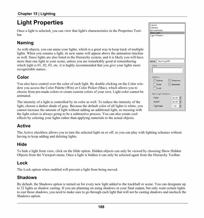
Chapter 15 | Lighting
Light PropertiesOnce a light is selected, you can view that light's characteristics in the Properties Tool-bar.
NamingAs with objects, you can name your lights, which is a great way to keep track of multiple lights. When you rename a light, its new name will appear above the animation timeline as well. Since lights are also listed in the Hierarchy system, and it is likely you will have more than one light in your scene, unless you are remarkably good at remembering which light is 01, 02, 03, etc. it is highly recommended that you give your lights more recognizable names.
ColorYou also have control over the color of each light. By double clicking on the Color win-dow you access the Color Palette (Win) or Color Picker (Mac), which allows you to choose from pre-made colors or create custom colors of your own. Light color cannot be animated.
The intensity of a light is controlled by its color as well. To reduce the intensity of the light, choose a darker shade of gray. Because the default color of all lights is white, you cannot increase the amount of light without adding an additional light, so messing with the light colors is always going to be a subtractive process. You can also create cool effects by coloring your lights rather than applying materials to the actual objects.
ActiveThe Active checkbox allows you to turn the selected light on or off, so you can play with lighting schemes without having to keep adding and deleting lights.
HideTo hide a light from view, click on the Hide option. Hidden objects can only be viewed by choosing Show Hidden Objects from the Viewport menu. Once a light is hidden it can only be selected again from the Hierarchy Toolbar.
LockThe Lock option when enabled will prevent a light from being moved.
ShadowsBy default, the Shadows option is turned on for every new light added to the trackball or scene. You can designate up to 32 lights as shadow casting. If you are planning on using shadows in your final output, but only want certain lights to cast those shadows, you need to make sure to go through each light that will not be casting shadows and uncheck the Shadows option.
188

Swift 3D V5 User Guide
When rendering to vector, designating which lights will cast shadows is only step one in the process of getting shadows to render out. Once you have all of your shadow settings covered in the Scene Editor, when you head over to the Pre-view and Export Editor, under the Vector Fill Options you also need to check the Include Shadows option. Shadows will also be covered in more detail in the Rendering with RAViX chapter. When rendering to raster, the EMO Ray Tracer will automatically honor the shadow options set in the light’s property page so no further steps are required.
SpecularAs with Shadows, you now have the option to make more than one light cast specular highlights on your object, and this is controlled through each light’s Property Page. All trackball and scene lights by default are specular, which refers to the light’s ability to create a bright spot on glossy surfaces. If you check the Include Specular Highlights in the Pre-view and Export Editor, you must uncheck this option for those lights that you do not want to cast specular highlights. Again, more detail on Specular Highlights will be supplied in the Rendering with RAViX chapter.
Spot Light OptionsWith Spot Lights, you have three additional options that control the characteristics of the light's beam. Fade Angle adjusts how wide the spot light will shine. Cutoff Angle refers to how wide the spot light's hot spot is. Tightness con-trols how quickly the light's intensity transitions between the hot spot and the fade angle. The higher the number, the quicker the light dims.
HierarchyAll lights are included in the Hierarchy system, which is accessible through the Hierarchy toolbar. Using the Hierarchy to select lights provides a great advantage when scenes start to get crowded. But what will really come in handy is that Free Lights can be made a child of any object (Target Lights cannot be children). When an object is made a child of another object, whatever you do to that parent object will be done to the child as well. Obviously the huge benefit is that if you animate an object, the light will follow that object along its animation path. Another thing to note is that nei-ther Free Lights or Target Lights can have children. Read more about establishing parent/child relationships in the sec-tion on Hierarchy in the Working With Objects chapter, and about creating Hierarchical Animations in the Animation chapter.
189

Chapter 15 | Lighting
190

Chapter 16 Cameras
OverviewShut your left eye.
I'm serious, go ahead and shut it. Now place your face right up against this page (or your screen if you're reading the electronic version). Now move your head around and look at some different things in the room. Hey, what else do you have to do right now… just do it. Ok, now get up out of your chair, run into the next room, spin around 3 times and then stand on your head. No? All right, forget it. The point is you've got two well-used cameras already built into your head, so there's not too much mystery involved with cameras.
You can open your left eye now.
Most of the cameras within Swift 3D work in a similar fashion to your eyes. You can look at different things by mov-ing your head around. You can see things up close and from far away by altering the space between your eyes and your subject matter. And if you're not pleased with your view, you can get up and reposition your cameras somewhere else. These cameras all show a Default Target view, where the laws of physics decide how large objects are in relation to the camera. One example of this Default Target effect would be a set of railroad tracks that disappear over the horizon. With the human eye, these tracks will converge to a single vanishing point. In addition, objects that are farther away from the camera will appear smaller than those objects closer to the camera. In the Advanced Modeler, you will also find Orthographic views, where these laws are disregarded. For information on Orthographic Viewports, refer to “2D Orthographic Viewports” on page 125 in Chapter 13: Advanced Modeler.
The cameras within Swift 3D can be used in two primary ways. First, they can be used as frames of reference. In other words, used to look into the world of Swift 3D from different Default Target s while creating your 3D scene. Second, they can be used to record any action that takes place in your scene. If you've got a scene with no movement, think of your camera as a single-frame picture camera, and if you've got any sort of animation then consider it more of a video camera. And just like a video camera, certain Swift 3D cameras can be physically moved around and pointed at things as you record the movement in your scene.
191

Chapter 16 | Cameras
Standard CamerasThere are six Standard Cameras that come with Swift 3D. I use the term ‘come with’ because you don't have to do any-thing to create them. The Standard Cameras are Front, Back, Top, Bottom, Right and Left. It might help to think of a big cube that surrounds your scene and each one of these cameras exists on the outside of that cube, looking in on the Swift 3D world. These cameras can serve as simple reference views or as integral parts of your animated scene. Each of these cameras can be used as the view that gets rendered upon export, but they cannot be animated themselves. Any camera animations need to be performed with the Free and Target Cameras.
You can change the camera view of each Viewport by clicking on the Viewport Menu button in the upper left hand corner of the Viewport and choosing an available camera from the list.
NOTE: In Swift 3D V5 you can now have multiple Viewports assigned the same camera.
Camera ModeTo maneuver any camera view within Swift 3D, you must hold down the ALT key (Win) or the COMMAND key (Mac) to enter into Camera Mode. The cursor will change to the Camera cursor to indicate you are in this mode.
PanningThe Standard Cameras are most beneficial when your animation does not involve any camera movement, but rather just the movement of objects. The limitation in panning the Standard Cameras is that they always face the exact same direction, as if they could only move along the surface of that imaginary cube I mentioned earlier. For example, the Front Camera always looks exactly along the Z axis. When you pan these cameras, it's more of a sliding motion (left, right, up and down) rather than a pivoting motion (as if you were standing in one place and pointing your camera in different directions).
To pan a standard camera:1. Hold down the ALT key (Win) or COMMAND key (Mac) to enter Camera Mode.2. Drag anywhere in the Viewport. The cursor will change appearance to indicate that you are panning the
camera. If you have the reference grid turned on you will see the grid lines, as well as any objects moving around in the Viewport, but remember it is actually the camera that is moving.
3. As soon as you release the mouse button, the camera pan icon will disappear.
ZoomingZooming a Standard Camera in or out will actually move the camera's location in 3D space. Because the camera is essentially the Viewport you are looking through, you don't see the camera actually moving. Instead, your scene appears to move closer or farther away from you. If you were to compare this process to using a regular picture camera, it would be akin to physically walking closer to or farther away from whatever it is you want to take a picture of. This differs from the terminology of picture cameras because zooming with a picture camera is actually done by changing the length of the lens. You can create a similar effect to zooming by changing the Lens Length (see the previous section on Lens Length under Camera Property Page), but there are other changes that happen to the view of your scene.
192

Swift 3D V5 User Guide
To zoom a standard camera:1. Hold down the ALT key (Win) or COMMAND key (Mac) to enter Camera Mode.1. Right click-and-drag (Win) or CTRL+ click-and-drag (Mac) anywhere in the Viewport. The cursor
will change appearance to indicate that you are zooming the camera.2. Drag the cursor upward to zoom in and downward to zoom out.
Additional controls that facilitate zooming in or out on particular areas of your scene can be found in the Viewport Menu:
• Frame All: All objects, lights and cameras in the Viewport will be framed in the camera view.• Frame All Objects: All objects only will be framed in the camera view.• Frame Selection: Any selected objects will be framed.• Reset View: The view will be reset so that the camera will again be focused at the center of the scene. Any zoom-
ing that has taken place will not be restored. If you want to look at it mathematically, it repositions the camera so that its coordinates are X = 0 and Y = 0, while Z remains the same. This function only works with the six Standard Cameras.
Frame All Objects ButtonLocated on the main toolbar, the Frame All Objects button has the same functionality as the Frame All Objects feature that is located in the Viewport Menu. A simple click will position the camera directly in front of all of your objects while zooming either in or out so that all of the objects are visible with only a slight buffer of space around the edge of the Viewport.
Reset Camera LocationClicking the reset button, which is located at the bottom of the buttons found on the left side of the Rotation Trackball, will open a menu which includes Reset Cam-era Location at the bottom. This has the same functionality as the Viewport Menu’s Reset View option and is available when no objects are selected within the View-port.
Default Target CameraThe Default Target Camera is a hybrid between the Standard Cameras and the Target Camera. The big advantage this camera has over the Standard Cameras is that it can be aimed. If you remember the earlier cube analogy, the Default Target Camera can be positioned anywhere on the surface or within the cube, and aimed in any direction. The disad-vantage of the Default Target Camera over the Target Camera is that any camera manipulation has to be done through the Viewport rather than moving the actual camera.
PanningSince the Default Target Camera has a target point, the only way to pan the camera up, down, left or right is by clicking directly on that target point
193

Chapter 16 | Cameras
To pan the Default Target view:1. Hold down the ALT key (Win) or COMMAND key (Mac) to enable the camera. The camera’s Target Point will
appear in the center of the Viewport. The Target Point designates where the camera is aimed.2. Click on the camera’s Target Point to activate the Camera Pan cursor.3. Drag the cursor to pan the camera in any direction.
ZoomingLike the Standard Viewports, zooming is the process of phys-ically moving the camera closer or farther away from its tar-get point. Zooming can therefore be done by clicking anywhere in the background.
To zoom the Default Target view: 1. Enter into Camera Mode.2. Right click (Win) or CTRL + click (Mac) on the cam-
era’s Target Point to activate the Camera Zoom cursor.3. Zoom in by dragging upwards and zoom out by dragging
downwards.
Rotating and RollingIn addition to panning and zooming, the Default Target View can also be rotated and rolled. Rotating the camera liter-ally moves the camera 360 degrees around the camera’s Target Point. Rolling the camera is the process of tilting the camera left or right.
To rotate the Default Target view:1. Enter into Camera Mode.2. Click anywhere in the Viewport except on the camera’s Target Point. A thin gray circle will appear as a visual
indicator of where you must click in order to rotate or roll the camera.3. Click-and-drag anywhere within the circle to rotate the camera. NOTE: If you rotate the camera so that it is look-
ing straight up or down the Y axis, the camera’s rotational movement becomes very sensitive.
To roll the Default Target view:1. Enter into Camera Mode.2. Repeat step 2 from “To rotate the Default Target view.”3. Click-and-drag anywhere outside the circle to roll the camera.
When you roll the Default Target Viewport, you’ll also notice a single green arrow within the Rotation Trackball that indicates which way the top of the camera points. You can use this arrow as a nice visual aid if you lose track of how the cam-era is tilted in the Viewport, or you can also control the roll of the camera by rotat-ing the camera directly in the Rotation Trackball (note that the Lock Spin button within the trackball is locked on.)
194

Swift 3D V5 User Guide
NOTE: You have the option to lock camera roll in the User Preferences dialog.
In addition to panning, zooming, rotating and rolling the Default Target View, you also have access to the same Frame All, Frame All Objects and Frame Selection options as the Standard Viewports. These options are located in the Viewport Menu.
Scene CamerasNow we're talking some serious cameras. With both the Free Camera and the Target Camera, the cameras themselves actually show up in the Viewport and can be manipulated as objects. This allows for much better camera control and facilitates camera animation like you wouldn't believe.
Adding Cameras to the SceneWhen you click the Create Free Camera or Create Target Camera buttons from the Main Toolbar, you will see a light blue rectangular-looking object appear in the Viewport (Target Cameras also come with a blue target point). This rep-resents the camera, but in order to actually view what the camera is seeing you must first change the view of one of the Viewports. New cameras get assigned a default name of Free or Target Camera01, Camera02, etc. and they can be selected from the Viewport Menu. You can create multiple Free and Target Cameras, but you may want to start naming them to keep track since cameras are all represented with identical icons in the scene.
Selecting Scene CamerasSelecting Scene Cameras can be done by choosing the Free or Target Camera from the Viewport Menu and clicking within the Camera's Viewport, like a Standard Camera, or by clicking directly on the camera icon itself in any other Viewport. Once you select the camera its icon will turn red.
You also have the option to select the camera via the Hierarchy toolbar. This is a simple process of scrolling through the Hierarchy list and clicking on the corresponding camera’s name. If there is more than one camera in the scene, this is when giving cameras meaningful names will come in handy because it might come down to trial and error figuring out which camera is Free Camera01 vs. Free Camera06. Once a camera is selected in the Hierarchy list it will turn red in the Viewports indicating that it is ready to be worked with.
Free Camera Target Camera
195

Chapter 16 | Cameras
Free Cameras
Free cameras are named as such because they can be pointed in any direction.
Positioning (Panning and Zooming)Free Cameras can be positioned using any of the following three methods:
1. Once the Free Camera is inserted, you can move it around by dragging the cam-era icon in the Viewport, just like a regular object.
2. You can also control its movements (panning and zooming) through the Free Camera's Viewport, much like you would a Standard Camera.
3. Through the numeric coordinate system found under the Camera Position prop-erty page.
You can choose which method is most appropriate, but I find that using the Free Camera's view for zooming and the secondary view for camera positioning works pretty well.
RotatingThe Free Camera can be rotated using either of the following two methods:
1. Select the Free Camera icon in one of the Standard Camera Viewports.2. Notice that the Free Camera icon now appears in the Rotation Trackball. Use the
Rotation Trackball as you would with any object to rotate the Free Camera in any direction.
Or,
1. Using the Viewport menu, select the Free Camera to be active in either of the View-ports.
2. Click anywhere in the background of the Free Camera Viewport.3. Notice that two arrows appear in the Rotation Trackball. These arrows are used as
references that show which way the camera is pointing (blue arrow) and which direction the camera's vertical axis is (green arrow). This is also where you would aim the Free Camera.
Target CamerasBetter known as ‘The ultimate Swift 3D camera,’ Target Cameras give you the same control over the cam-era's positioning, but add the ability to aim the camera at specific locations in the scene via the target point.
PositioningAs with the Free Camera, the Target Camera can be positioned by clicking on the camera icon in one of the Standard Camera views and dragging it to a new location. This is the equivalent of panning or zooming a Standard Camera. Notice that the Target Camera moves independently of its target point. This means that when you move a Target Cam-era, the target point will always remain in the same spot, and when you move the target point, the Target Camera will
196

Swift 3D V5 User Guide
always stay in exactly the same spot.You can also animate the positioning of the Target Point separately from that of the camera itself.
Because the Target Camera has the addition of its Target Point, its Camera Position page also allows you to numeri-cally position both the camera and its target point.
A final way of positioning the Target Camera is by selecting it from the Viewport Menu. The panning and zooming of a Target Camera view is identical to that of the Default Target Camera.
RotatingRotating the Target Camera can be done by clicking on its Target Point and dragging it to a new location, as discussed in the previous section. In addition, when the Target Camera is selected as an active Viewport, it can be rotated using the same method as rotating the Default Target Camera.
RollingUse the same methods for rolling a Default Target Camera to roll the Target Camera.
Nick's TipsWe've all got preferences in life, and here's mine. When working with Free or Target Cameras, I like to use the
left Viewport as my camera view and use the right Viewport as my scene view, keeping it set to the Top view most of the time. My rationale is that the left Viewport is always the one that gets rendered upon export, and when I'm doing camera animations the likelihood is high that I'll want to render what that camera actually sees. As far as the Top view goes, I feel this particular view gives you the best reference of where things are in the scene, much like a Plan view in architectural drawings. Of course this can vary depending on how your scene is constructed.
Camera Property PageNameIf you are using one of the Standard Cameras, this option will be grayed out, but you can rename any Free or Target Camera that you insert into your Scene.
Lens LengthI really don't want to bore you with the intricacies of lenticular optics. (Actually, I have no idea what lenticular optics means, but the “I don't want to bore you with” stuff sounds so much more intelligent than the “I have no idea what” stuff. But I'm going to fake it anyway.)
When you lengthen the lens of a camera, it magnifies the image. Because it magni-fies the image, you must move the camera farther away from your scene to get an all-encompassing view of your objects. An additional side effect of having a very mag-
197

Chapter 16 | Cameras
nified view is that the camera's field of view becomes very concentrated. In other words, the longer the lens, the smaller the scope of what can be seen through that lens.
Rendering Camera ViewsWhen it comes time to render your scene, whichever Viewport is currently active will be the one that is rendered.
Swift 3D can only render one camera view at a time, which means you cannot render your animation from multiple camera views. If rendering from more than one camera is required by your project, render each camera view separately and then composite the files in Flash.
198

Chapter 17 Animation
OverviewThe addition of animation to any 3D scene is certainly the next logical step towards coolness. In the old world of pre-rendered animations that ZAM 3D’s parent product, Swift 3D, was so adept at rendering, animation was key. However, since WPF offers a real-time 3D renderer, you need to think about where you would like to be animating your objects. Furthermore, the ability to allow users to interact with your 3D models adds another chapter to this whole animation story.
While it's all fine and dandy to have these new options, let's be clear about creating 3D animations outside of ZAM 3D...it's not necessarily easy. Although Blend is a terrific interface design tool, its 3D animation capabilities are not all that robust. Also, allowing for real-time user interaction with your 3D objects in WPF requires some more in-depth knowledge of programming code. So when you start pondering the question of where to generate your animations, just follow the general rule of "Anything complex should be done in ZAM 3D." The bottom line is that ZAM 3D is built specifically for dealing with 3D modeling and animation, so you'll find it the most comfortable environment to create anything more complex than a simple rotation. With that said, let's dive into this world of motion. Which leads us to our next discussion.
Swift 3D has solved the confounding problem of creating quality 3D images in a vector-based file format. Swift 3D has terrific creation and animation tools that allow you to create dynamic scenes. But Swift 3D is NOT the panacea of the low-bandwidth 3D world. By that, I mean that just because you can export vector files from Swift 3D does not implic-itly indicate that every animation you crank out of the software will be Web-friendly.
But maybe you bought Swift 3D for the sole purpose of creating animations for the Web. Don't panic. You've got the perfect tool, but you just have to use it the proper way to keep your exported files within reasonable size proportions. Understanding the limitation of how 3D converts to 2D vectors is very important when designing your scenes. On the other hand, if you have no limitations on file size, for instance if you're creating CD or DVD presentations, or some-thing that will be viewed over a network or on a local machine, you don't necessarily have to pay attention to any of this low-bandwidth gibberish I'm spouting.
When displaying 3D animations in a 2D environment (like the Flash Player for example) it is always a process of sequential keyframes. That means that if you have a 100-frame animation within Swift 3D, when you render your file you will have 100 keyframes to work with. Since neither the Flash Player nor the SVG Viewer supports native 3D objects, Swift 3D has to tell these plug-ins exactly what to show for each frame of your animation.
199

Chapter 17 | Animation
And what does this mean to your average Web designer, you ask? Use 3D wisely! When creating animations for the Web, Swift 3D is best suited for creating short animations that become part of a larger scene or movie. Not to say that you can't create long and detailed self-contained animations that look great, but you might not be able to stream them to a 28.8 kbs modem too well.
So let's take a look at Adobe Flash, a popular vector graphics editor that you will probably be using your 3D anima-tions in conjunction with. Flash too can create exciting animation, and its strongest selling point is the ability to do so without creating large files. So realizing what you can do best in Swift 3D and what you can do more efficiently in a vector editing application is very important as you start designing your scenes.
Two-dimensional vector editors do a great job of moving objects around in 2D space, and making them change shape over time. What these editors can't do well is spin, rotate or flip objects in 3D space. These are the features that Swift 3D specializes in. So, with that said, try to keep in mind what types of movement are best done with Swift 3D—rota-tion animations—and what things you'll be better off doing in your 2D vector editor of choice—scale and position ani-mations.
Animate ButtonThis all-powerful toggle button located just below the Animation Timeline slips you in and out of animation mode. When this button is toggled off, nothing you do to your scene or the timeline will affect your animation. When it is toggled on, any changes you make to your scene will be recorded as keyframes in the timeline and thus affect your overall animation. The best way to use this button is to set up your entire scene first, turn the Animate button on, and then proceed to develop your animation using the techniques covered within this chapter.
Animation Timeline ToolbarThis toolbar is where you control all aspects of animation in your scene. The timeline is divided into frames, much like the individual frames of a movie. The more frames, the longer the movie, unless you start to mess with the Frames Per Second control that will be discussed in a moment. You can either create animations by changing each of the individual
200

Swift 3D V5 User Guide
frames (takes awhile—don't bother), or create several keyframes and let Swift 3D interpolate or ‘tween’ the animation in between (definitely the way to go).
Selection NameThe Selection Name window of the animation timeline displays the name of your currently selected object. Since the Animation Timeline is selection dependant, the timeline shows the animation properties for whichever object, camera or light is selected, and thus displayed in the Selection Name window. To better organize your more complicated scenes, you may find the naming process covered in the chapter on Working With Objects useful.
Current Frame IndicatorThe Current Frame Indicator shows what frame your scene is currently in. By default, the Current Frame Indicator is on frame zero. Once you toggle the Animate button on, you can slide the Current Frame Indicator to a later frame, make changes, and these changes will create keyframes in the timeline, thus animating your scene.
Once an animation has been created, you can use this red bar to preview your animation or move to a specific frame for further editing. The dark gray bar behind the current frame indicator shows the total number of frames in your anima-tion.
Animation PropertiesThere are several properties of an object that can be animated, and all of those properties are listed along the left side of the timeline. Although certain types of objects can have certain types of animation properties, here is a list of all the possible properties that can be animated:
1. Position: This property pertains to any animations involving objects that change their location on the X, Y, Z coordinate grid.
2. Pivot: Any object that has an associated pivot point can have an animated Pivot property.
Selection Window
Playback Controls
Frames Per Second Control Animation Path Mode Button
Timeline Scale bars
Loop Toggle Button
Current Frame Indicator Keyframes
Animate Button
201

Chapter 17 | Animation
3. Rotation: If an object has its rotation animated, this is where it will show up. This could be any object except for the Target Cameras and Target Lights.
4. Scale: When objects change their scale over time, this property will reflect that change.5. Shear: When objects change their shear over time, this property will reflect that change.6. Material: The material property will be designated by listing out all of the surfaces that have been defined for
that object. This could be a fairly lengthy list if numerous surface groups have been defined in the Advanced Mod-eler. Note: Color applied to lights cannot be animated.
7. Shape: The only object that can animate its shape is the Tetrahedron.8. Scale Axis: This is also a Tetrahedron-specific animation property.9. Roll: This property only applies to Target Cameras and Target Lights, and it indicates when a camera or light is
rolled to the left or to the right.10. Path: If you have animated the path of an extruded or lathed object, the animation will appear here.
Playback ControlsThese control buttons allow you to view your animation, as well as jump around in the timeline.
Play: Does just that.Stop: The opposite of play.First Frame: Moves the scene to the first frame of your animation.Previous Frame: Moves the scene back one frame.Next Frame: Advances scene to the next frame.Last Frame: Advances scene to the last frame of your animation.
Timeline Zoom FactorThe Timeline Zoom Factor setting allows you to zoom the timeline in or out by a factor of up to 10X.
Frames Per SecondThe Frames Per Second Control allows you to adjust how quickly the frames of your animation will play after export-ing to a file. The more frames that get viewed each second, the more smoothly your animation will play. But the more frames that get exported to a file, the larger that file will be, so there is always a subjective decision to get made here. The default of 12 frames per second has proven itself to be very effective for use on the Web but it's important to note that when you import Swift 3D files into Flash, it will override any adjustments you make in Swift 3D and revert back to its default setting.
NOTE: The default Frames Per Second setting can be adjusted by going to Setup > User Preferences.
Loop AnimationThis little button determines how Swift 3D will render your final file with regards to creating looping animations. If you are creating a linear animation where your last frame is not the same as your first frame, you want to turn this but-ton off. If you're attempting to create a seamlessly looping animation where your first frame is identical to your last frame, you should turn this button on (default configuration). You see, when your last frame is the same as your first frame and you loop the entire animation, you'll end up with two identical frames in a row, which will manifest itself as
202

Swift 3D V5 User Guide
a pause in your final animation. When you toggle the Loop Animation button on, Swift 3D automatically skips the ren-dering of your final frame so that you don't end up with that unsightly pause.
This will in no way affect whether or not your animation loops when played in the Flash Player or when imported into Flash. By default, all SWF animations rendered from Swift 3D will automatically loop when played in the Flash Player, and all SWF files imported into Flash will not loop unless told to do so with specific Flash commands.
NOTE: The default state of the Loop Animation button can be adjusted by going to Setup > User Preferences. It can also be turned on and off from the Animation menu.
Animation GalleryThe drag-and-drop animations are the easiest way to get your scene moving. We've supplied you with some com-mon animations within the Animation Gallery that cover the basics. You know, spin right, clockwise spin, 45-degree right spin. The typical anima-tions you might want to apply. To pre-view the animations just click on the thumbnail image and you'll see a small-scale rendition of the action. To apply them to your image just click-and-drag from the Preview Window onto whatever object you wish to be animated. When you apply an animation from this gal-lery, the Animate toggle button does not automatically turn on so if you want to edit the animation you need to first toggle on the Animate button. The default length of the drag-and-drop animations is 20 frames, but that can be easily adjusted using the techniques covered later in this chapter.
To apply a drag-and-drop animation:1. Click on the Animations button in the Gallery Toolbar.2. Choose an animation that you like.3. Click-and-drag from that animation's preview window.4. Move your cursor over the object or group of objects and release the mouse button.5. Click the Play button on the Playback Controls to view your animation.
Applying more than one drag and drop animationYou can apply a spin, deformation and fly by animation all to one object if you so choose. However, you cannot apply two animations from the same category, such as two different types of Common Spins. If you try to do this the second animation applied will simply override the first animation.
You can, however, create a nested animation by applying one animation to an object, then group that object with other objects, and then apply a second animation to the grouped object. In this case, the original object will carry out its first animation while partaking in the second animation as well. You can nest these animations several layers deep.
203

Chapter 17 | Animation
Animation Drop TargetThis feature only applies to Text or Grouped objects. When this button is off, any drag-and-drop animations will be applied to your entire text object or grouped objects as a whole. When this button is toggled on, drag-and-drop animations are applied to each of the characters in a text object individually or each individ-ual object in a group. For example, if you drop a spin onto your text while the Drop Target button is toggled on, each individual character will spin around their respective axis.
If you want to apply a drag-and-drop animation to just one character, hold down the CTRL button while dragging the animation to the desired character. Make sure the Animation Drop Target button is not toggled on.
Scenes can get very confusing when you start to animate individual characters in text objects. I wouldn't do much more than apply spins to characters since changing their paths really creates chaos. If you need to delete an animation for an individual character or individual object within a group, hold down the CTRL key as you select that character or object. Its animation properties will appear in the animation timeline and you can delete the animation by right clicking (Win) or CTRL + clicking (Mac) on the timeline and selecting Delete All Key Frames.
Saving an Animation to the Animation GalleryAs you become more familiar with Swift 3D and start generating some cool animations, you may come across some-thing you'd like to save for later. Not the image, mind you, but the animation scheme. Swift 3D allows you to take your self-created animations and turn them into drag and drop animations for easy application at a later date.
To create your own drag-and-drop animation:1. Design an animation you like.2. Select the object that has the killer animation you want to preserve.3. From the file menu, choose “Save Animation...”4. This will bring up the Gallery Setup dialog, from which you can choose a name and location within the Animation
Gallery for your scheme.5. Use the Set Display Frame controls to choose what frame of your anima-
tion to show in the preview window.6. Click OK.
An animation added to the Gallery can only be edited by clicking and drag-ging it back onto an object. Once an animation is placed back into the scene it no longer has any connection to the original animation stored back in the Gallery. If changes are made to the animation it must be saved back to the Gallery. If you do not desire two copies of the animation simply overwrite the previous animation or go back and delete it from the Gallery.
You can right click (Win) or CTRL + click (Mac) on the palette window sur-rounding the thumbnails to bring up the Gallery Setup dialog, from which you can delete, rename or relocate any gallery content. For more detailed information on how to share Gallery content and organizing/managing Gal-leries in Swift 3D, see the section on Galleries in the Scene Editor chapter.
204

Swift 3D V5 User Guide
Keyframe AnimationUnderstanding keyframes and how they work is an important step in creating animations quickly. Sure, you can tell Swift 3D exactly what you want your scene to look like in every frame, but you'd be better off using the built-in tween-ing functions associated with the Animation Timeline. Basically, keyframes represent points in an animation where you can make important changes take place. In between the keyframes, Swift 3D will make all the decisions on how your scene changes automatically. The keyframes simply give Swift 3D reference points to work from while it decides how to create the transitional frames using the tweening process.
To create a basic keyframe animation using the timeline:1. Create a scene with at least one object.2. Toggle the Animate button on.3. Click-and-drag the Current Frame Indicator to the desired frame number, setting your animation length.4. Manipulate your object(s). For each Animation Property that you change there will be a corresponding keyframe
added to the timeline.5. To view your animation, press the Play button.
Start and Stop Keyframe ControlsWithin the Animation Timeline, each keyframe has a Start Animation and a Stop Animation control. Within one frame the controls are set to the same value so there is no pause. Adjusting these controls allows you to stop one aspect of an animation for as long as you want. For example, you may want a spinning text object to pause mid-spin so it's easier to read. We've used the universal “Green equals Go, Red equals Stop” color scheme to make it obvious when an object is going to move, rotate or change size, and when it is going to stop doing those things.
To pause an animation:1. Toggle the Animate button on.2. Position your cursor over the left half of the keyframe bar.3. When you get the Left Directional Arrow, click-and-drag to where you want your animation to begin its pause.4. If you want to adjust the Animation Start Time, do the same on the right half of the keyframe.5. To adjust the location of the pause, position your cursor over the Red Bar in between the start and stop animation
control bars and click-and-drag to reposition the entire keyframe.
Adjusting Animation LengthThis feature is a big time saver because it allows you to scale your animations without having to adjust every single keyframe involved. The first technique involves scaling an entire animation at once. In this case, every single keyframe of every single object, camera and light will be adjusted in proportion with each other simultaneously.
To scale an entire animation:1. Toggle the Animate button on.2. Click-and-drag on the bar located just beyond the last frame of your animation in the upper section of the timeline
where the frame numbers are displayed.3. Move the marker to your desired ending frame.
205

Chapter 17 | Animation
4. Release the mouse button.
To scale the animation of an object:1. Select the object whose animation length you would like to alter.2. Toggle the Animate button on.3. Click-and-drag on the long bar at the end of your object's Animation Properties (e.g. Position, Scale, etc.).4. Move the marker to your desired ending frame.5. Release the mouse button.
Keyframe Properties
Linear Frame SpacingLinear Frame Spacing has to do with how much your objects move between each frame as they transition through a keyframe. This feature can be adjusted on a per keyframe basis and is accessed by right clicking (Win) or CTRL + clicking (Mac) on individual keyframes in the Animation Timeline. Linear Frame Spacing is listed in the context menu that appears, with its on and off state indicated by the checkmark placed in front of it in the menu.
The default is to have this feature turned off (unchecked), which allows Swift 3D to automatically ease objects into and out of a keyframe. This is accomplished by adjusting the distance an object travels between frames as it approaches and leaves a keyframe. Since this is an automatic setting that slows an object down as it enters a keyframe and speeds it up as it leaves the keyframe, you do not have any control over how fast or how slow objects enter and leave keyframes.
When Linear Frame Spacing is turned on (checked), Swift 3D will move the object at a consistent speed throughout the animation, meaning the object moves the same amount of distance between each frame of the animation.
NOTE: This setting is only applicable to path animations, where objects are moving from one point to another.
Keyframe EasingNew easing controls work with the keyframes in your animation timeline to smooth out position, rotation, and scaling transitions. These easing con-trols add more realism to the motion dynamics of your 3D animations.
This feature is accessed by right clicking (Win) or CTRL + clicking (Mac) on individual keyframes and selecting Properties. Doing so will open the Keyframe Properties dialog box, where you can adjust Ease To/Ease From by moving their respective sliders to the left and right. Changes made to the slider will be reflected in the graph, displaying the degree of motion over time.
Easing applies to every transform possible, including Mesh Morphing, Color, Shape Animations, etc.
206

Swift 3D V5 User Guide
Editing Keyframes and AnimationsSwift 3D provides you with some really easy-to-use techniques for working with your animations once they have been created.
Copying and Pasting KeyframesIf you have the need to create a keyframe identical to an existing keyframe, you can use the Copy/Paste Keyframe function. The most common use of this is when you have an animation that you would like to loop; having the same starting and ending keyframes insures a smooth loop in your animation. (See the section on the Loop Toggle button earlier in this chapter for more information on looping animations.)
Keyframes cannot be copied from one project to another, but if you copy an animated object from one project to another, its animation will come along for the ride.
To copy and paste a keyframe:1. Select the object whose animation you would like to edit.2. Toggle the Animate button on.3. Right click (Win) or CTRL + click (Mac) on the keyframe you would like to copy, and choose Copy Keyframe
from the context menu.4. Move your cursor over the frame you would like to paste the keyframe into.5. Right click (Win) or CTRL + click (Mac) on that frame and choose Paste Keyframe from the context menu.
Nick’s TipsThe copy and paste keyframe feature can also be helpful when you want to reverse your animation. For exam-
ple, if you are creating an animation that has a text string and you want each letter of that text to start out of view and then fly into the center of your Viewport, it is easiest to start creating the animation with your text already in place in the center of the Viewport. From there, you can move the keyframe indicator over and move each letter so that they fly away from the center of the Viewport and out of sight. Now all you need to do is copy the first keyframe to a spot beyond your final keyframe, and then copy the final keyframe into the first frame. Adjust the new final keyframe back to where you want the animation to end, and you have reversed your animation. Another option is to export your initial animation and use Flash’s Reverse Animation feature.
Deleting KeyframesThere are a few different methods of deleting parts of your animations depending on how much of the animation you would like to get rid of.
To delete an individual keyframe:1. Select the object whose animation you would like to edit.2. Toggle the Animate button on.3. Right click (Win) or CTRL + click (Mac) on the keyframe you would like to delete.4. Choose Delete Keyframe from the menu.
207

Chapter 17 | Animation
To delete the selected object, camera or light animation:1. Select the object or camera whose animation you would like to delete.2. Toggle the Animate button on.3. Right click (Win) or CTRL + click (Mac) anywhere in the timeline.4. Select Delete All Keyframes from the context menu.
To delete all object animations:1. Choose Edit > Delete Object Animations.2. When the warning message appears, click OK.
To delete all animations:1. Choose Edit > Delete All Animations.2. When the warning message appears, click OK.
Nick’s TipsThe easiest way to conserve on file size is to make your animations as short as possible, while still meeting
your overall design goal. Two techniques of accomplishing this are as follows:
1. If you have a symmetrical object, like a box for instance, with a rotation animation applied to it, you can export just a section of the rotation and then loop the animation to simulate a full turn. In the case of the box, it's got four sides, so a quarter turn is all you need to get a seamless rotation.
2. If you have a logo or spinning text, you can render only the frames where the artwork is facing the camera and then loop the animation. This will give you the effect of a full 360-degree spin while never having your logo or text facing backwards.
Editing the Animation PathAll animation paths of objects, lights and cameras can be edited by clicking on the Animation Path Mode button located to the left of the Animate button below the Animation Timeline. This button will not become active until you first click on the Animate button to go into Animating mode. Once the Animation Path Mode button is selected, if there is an animation path present it will become visible in each Viewport. Since you can enter into Animation Path Mode at any time during the animation process, if you have not yet created an animation then the path will not become visible until you start adding keyframes.
Each keyframe in the path is represented by a blue square, which is called the Keyframe Control Point. This icon can be moved to a new location anywhere along the x, y or z axis just like you would move an object. You will also have access to each control point's Bezier control handles, which are designated by green squares. When either a control point or control handle is selected it will become red. In order to move an entire path to a new location, this is done by relocating the object itself.
NOTE: When Animation Path Mode is turned on, if you position an object by clicking on the Keyframe Control Point (which is also the object's pivot point) a new keyframe will not get added to the timeline. Clicking on the Keyframe Control Point only adjusts the position of that keyframe, regardless of whether or not the red keyframe indicator is
208

Swift 3D V5 User Guide
moved to a new point on the timeline. Therefore, to insert a new keyframe you have to click on a surface area of the object that is away from the Keyframe Control Point and then drag the object to a new location.
Bezier Path PropertiesOnce in Animation Path mode a new page will appear in the Properties Toolbar called Bezier Path.
Point TypeEach keyframe control point can be designated as a Corner, Curve or Tangent point. When you create an animation each keyframe control point will be a Curve Point by default. You can either change the point type after the animation is made, or you can choose the point type before you create each keyframe.
A Corner Point does not contain any information that defines how the animation path enters or exits that point since these points are always connected with perfectly straight lines. Adjusting the Bezier handles of Corner Points therefore has no impact on the animation path.
The Curve Point is defined by something called a Bezier curve and therefore comes with handles (the green squares) that provide control over the shape of the animation path entering and exiting the point. Although you can control the entry and exit, the two halves of your animation path are linked to each other so positional changes to one half of your point may have an effect on the other half of the Bezier curve.
The Tangent Point is very similar to the Curve point but it allows you to control each side of the curve's control points separately. The tangent point is designed to allow your animation path to enter and exit the point with completely different paths.
NOTE: If the Bezier handles for a Curve or Tangent Point are not displayed, CTRL (Win) or OPTION (Mac) + click and drag on the green control point to pull the Bezier handle out for display and edit-ing.
PositionIf you need precise control over the exact location of each keyframe control point you can adjust the X, Y and Z posi-tion of the points by entering the exact coordinates.
Orient to PathWhen the Orient to Path option on the Bezier property page is checked, Swift 3D takes the animated object and aligns it along the path according to its starting rotation. As the object moves through the keyframes along the path, Swift 3D automatically rotates the object in order to maintain its orientation to that path. Note that the orienta-tion of the object is dependent on the location of the pivot point, so you can adjust the pivot point in order to control where the object is pinned to the path.
209

Chapter 17 | Animation
In addition to its forward direction you also need to define the Up Axis so that Swift 3D knows which direction is "up" as the object moves along the path. From the Reference dropdown list you have the following Up Axis options: X Axis, Y Axis, or Z Axis. So, for example, if you have set an air-plane along a path that moves only along the X and Z planes, meaning that the airplane is maintaining its elevation but moving forward or backward and left or right, the logical Up Axis would be the Y Axis. And if it was a stunt plane that was flying in loops, so that its circular motion was along the Y and Z axis, the Up Axis would be the X Axis.
Of course these examples are both straightforward path animations that move only along 2 axes, so decisions need to be made when animations are introduced with paths that move along all three axes. Since you can only select one Up Axis, you need to choose the most logical direction for that object. Depending on the path, the object may flip its rotation at certain points. Going back to the airplane example, if the two animation paths were combined so that the plane stayed along the X and Z axis and then did a vertical loop along the Y axis, if the Up Axis was set to Y the plane's rotation will flip 180 degrees as the animation path became parallel with the Y axis.
Nick's TipsYou are not limited to the orientation that Swift 3D sets for an object as it moves along a path. Use the local
rotation setting, found on the Rotation property page, to further refine an object's rotation during the animation. Keep in mind that when an object is set along a path, it is the object’s bounding box that maintains its orientation to the path, so when its local rotation is changed, the global orientation of that object to the path is not altered. For example, if the airplane is flying a figure 8 path, use the local rotation of the object to bank the airplane as it moves around the curves.
Setting Objects to an Existing PathIf you want to set other objects in your scene to this animation path you must first save the path to the Animation Gal-lery. After the path is saved, you can apply it to other objects in the scene. Once the path is applied, you can click on the object and go to the Bezier Path property page to set how you want that object to orient to that path. Any other adjustments to the path can also be made using any of the previously discussed path editing techniques. If you edit that path keep in mind that if you want to be able to apply the newly edited path to a different object you need to save it as a new animation to the Animation Gallery.
Animating ScaleSwift 3D allows you to animate either uniform or non-uniform scale of an object. The first step in understanding non-uniform scaling is to know that every Swift 3D object has three different Scale Axes: width, height and depth. When you select an object and go to the Scale page of the Properties Toolbar you will see the object's default settings of 1.00, 1.00 and 1.00. These are the three settings that you can animate, and the process is different than changing the sizing of an object (covered in the Scaling section of the Working With Objects chapter).
To animate uniform scaling of an object:1. Toggle the Animate button on.
Airplane animated along the X and Z planes with Up Axis set to Y
210

Swift 3D V5 User Guide
2. Select the frame you would like your scaling animation to end.3. Click the Scaling Mode button.4. Click-and-drag on the object to rescale it proportionately.5. Release your mouse button when it's the correct size.
NOTE: The Scaling Mode button is a one-time deal, so if you want to make further scaling adjustments you'll need to click that button each time.
To animate non-uniform scaling of an object:1. Toggle the Animate button on.2. Select the frame you would like your scaling animation to end.3. Select the object you would like to scale.4. Click on the Scale page in the Properties Toolbar.5. Adjust the Scale Axis you wish to animate, or change all three.
Animating MaterialsThe animation of materials is basically the process of telling Swift 3D what you want your object's color to be at the start of your animation and at the end of the animation, and letting the program do the rest for you. As soon as you ani-mate a material, you will see the related keyframes appear in the Animation Timeline under the Material animation property.
To animate materials:1. Apply a material to your object in the first frame of an existing animation.2. Toggle the Animate button on.3. Move the Current Frame Indicator to the frame you'd like your material animation to end.4. Apply a second material.
Animating LightsA very slick feature in Swift 3D is the ability to animate your lighting scheme. You can accomplish this feat by either animating Trackball Lights or by animating Scene Lights.
To animate trackball lights:1. Create a scene with at least one object.2. Adjust your Trackball Lights as desired.3. Toggle the Animate button on.4. Move the Current Frame Indicator to the end of your desired lighting animation.5. Adjust your Trackball Lights as desired.
Your lights are now animated, with their positions being tweened from the start frame to the end frame. You can track their movement by watching the lighting trackball while the animation plays.
211

Chapter 17 | Animation
To animate scene lights:1. Create a scene with at least one object.2. Insert the desired lights into the scene and adjust their positions accordingly.3. Remove any Trackball Lights as needed (not required).4. Toggle the Animate button on.5. Move the Current Frame Indicator to the end of your desired lighting animation.6. Change the location of your Scene Lights as desired.
Animating CamerasIn Swift 3D you can only animate Free and Target Cameras; you cannot animate the Standard Viewport Cameras.
To animate a free or target camera:1. Create a scene with at least one object.2. Insert a Free or Targeted Camera.3. Position your camera where you want the camera animation to start.4. Toggle the Animate button on.5. Select the frame you would like your camera animation to end by moving the red Current Frame Indicator.6. Adjust the position of your camera.
You can create as many keyframes as you'd like to insure your camera animation is just as it should be. You can also animate any objects and lights in conjunction with your camera animations.
Hierarchical AnimationsThe universal scene properties contained within the Hierarchy system can play an integral part in creating more com-plex animations. The same parent/child and sibling relationships that can help you organize your scene effectively can be the key to unlocking some amazing animation capabilities.
The basic principles of parents and children that work for object manipulation within your scene will hold true for objects, lights and cameras when they are in motion. For example, if you create a sphere that is the child of a box, when you animate that box you will also be animating the sphere based on their relationship with each other.
The best example I can think of to demonstrate this technique of relational animations would be creating a 3D scene that shows how the moon rotates around the earth while the earth rotates around the sun. Since the earth is stuck in orbit around the sun, it would be considered its child. And in turn, since the moon is in orbit around the earth, it’s con-sidered a child of the earth.
To create a “solar system” animation using Hierarchy:1. Add three spheres to the scene that represent the Sun, Earth and Moon.2. Go to the Hierarchy toolbar.3. Create the relationships between the three objects, making the earth a child of the sun and the moon a child of the
earth.4. Create an animation of the moon rotating around the earth, and then the earth rotating around the sun.
212

Swift 3D V5 User Guide
By establishing the relationships ahead of time you can simplify the animation process and allow yourself some more creative animations.
If you decide to change the relationships between objects, you will not notice any differences in the animation unless you decide to further animate the objects. Once those relationships are broken, Swift 3D will retain the animation information for the objects, but will no longer be able to relate those objects with one another since they would have been disassociated with one another.
For additional information on establishing parent/child relationships, read section on Hierarchy in Working with Objects chapter.
Path MorphingThe ability to animate paths in the Extrusion Editor or Lathe Editor is referred to as Path Morphing. Both the Extrusion and Lathe Editors include their own animation timeline that behaves the same way as the main timeline in Swift 3D. The only difference in these timelines is that only the paths of either your extrusion or lathe object will appear within the layer area, rather than the properties of those paths. This way you can keep track of multiple paths without having to select each one individually.
To animate a path:1. Toggle the Animate button into animate mode.2. Adjust the Current Frame Indicator to the place you want to
insert a keyframe.3. Move the point or points you want to animate. 4. Swift 3D will automatically insert keyframes accordingly.
When you return to the Scene Editor you will notice when you select the extrusion a Path animation now exists in the Main Animation Toolbar timeline. You will probably have to enlarge the Animation Toolbar in order to see the Path animation in the timeline.
NOTE: You cannot change the types of points over time. For instance you can’t turn a Tangent Point into a Curve Point part way through an animation. Also, if you delete or add points to an extrusion or lathe partway through an ani-mation, those points will either be deleted or added to the extrusion for the entire animation of that path.
213
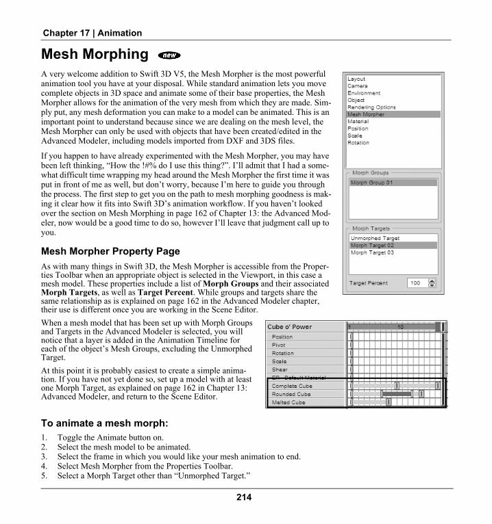
Chapter 17 | Animation
Mesh Morphing A very welcome addition to Swift 3D V5, the Mesh Morpher is the most powerful animation tool you have at your disposal. While standard animation lets you move complete objects in 3D space and animate some of their base properties, the Mesh Morpher allows for the animation of the very mesh from which they are made. Sim-ply put, any mesh deformation you can make to a model can be animated. This is an important point to understand because since we are dealing on the mesh level, the Mesh Morpher can only be used with objects that have been created/edited in the Advanced Modeler, including models imported from DXF and 3DS files.
If you happen to have already experimented with the Mesh Morpher, you may have been left thinking, “How the !#% do I use this thing?”. I’ll admit that I had a some-what difficult time wrapping my head around the Mesh Morpher the first time it was put in front of me as well, but don’t worry, because I’m here to guide you through the process. The first step to get you on the path to mesh morphing goodness is mak-ing it clear how it fits into Swift 3D’s animation workflow. If you haven’t looked over the section on Mesh Morphing in page 162 of Chapter 13: the Advanced Mod-eler, now would be a good time to do so, however I’ll leave that judgment call up to you.
Mesh Morpher Property PageAs with many things in Swift 3D, the Mesh Morpher is accessible from the Proper-ties Toolbar when an appropriate object is selected in the Viewport, in this case a mesh model. These properties include a list of Morph Groups and their associated Morph Targets, as well as Target Percent. While groups and targets share the same relationship as is explained on page 162 in the Advanced Modeler chapter, their use is different once you are working in the Scene Editor.When a mesh model that has been set up with Morph Groups and Targets in the Advanced Modeler is selected, you will notice that a layer is added in the Animation Timeline for each of the object’s Mesh Groups, excluding the Unmorphed Target. At this point it is probably easiest to create a simple anima-tion. If you have not yet done so, set up a model with at least one Morph Target, as explained on page 162 in Chapter 13: Advanced Modeler, and return to the Scene Editor.
To animate a mesh morph:1. Toggle the Animate button on.2. Select the mesh model to be animated.3. Select the frame in which you would like your mesh animation to end.4. Select Mesh Morpher from the Properties Toolbar.5. Select a Morph Target other than “Unmorphed Target.”
214

Swift 3D V5 User Guide
6. Set Target Percent to 100.7. Click the Play Animation button to preview your work.
Congratulations! While a simple example, you’ve now created your first mesh animation, opening up endless possibil-ities. However, before you run off to create a feature length animated extravaganza there are a few more details you should know that could make that production a lot easier.
Target PercentFirst of all, as you no doubt noticed if you used the numeric steppers to set Target Percent, this setting moves the animation from the initial Morph Target to the end target. This is the same as dragging a frame indicator though a timeline, however since we don’t know how many frames may be in any given animation it is expressed as a percentage of the anima-tion’s length. The real power of Target Percent comes into play when you have more than one modified Morph Target. By default Unmorphed Target is assigned 100% and additional Morph Targets default to zero.
When you assign a Morph Group to a keyframe, it includes all of that groups associated Morph Targets; however unless their Target Percents are set to something other than zero, they make no visible change to the model. This is where the real power of the Mesh Morpher becomes apparent. By setting the Target Percent for multiple Morph Tar-gets to various percentages, they are blended to give the mesh object an entirely new appearance. As a result, multiple morph groups can be animated at the same time. Combine this feature with the fact that you can have unlimited Morph Groups, unlimited Morph Targets, and control how they blend using Target Percent, the animation possibilities are truly limitless.
215

Chapter 17 | Animation
216

Chapter 18 Preview and Export Editor
OverviewWhy have just one rendering engine when you can have two? Well, our engineers asked the very same question and couldn't come up with a reason NOT to double our output power by including both a vector renderer - known to many as RAViX - and a raster renderer - a.k.a. EMO. These two powerhouses are responsible for taking your beautifully crafted scene and turning it into an actual file that you can use. And the wonderful thing about this flexibility is that your single scene can have many afterlives once it leaves the world of Swift 3D. Use RAViX for your lightweight Flash work. Use EMO for your high-bandwidth video production. Or use them both together for insane effects that are super realistic, yet small in size.
But I'm getting ahead of myself since both of these rendering beasts have their own chapters to brag about their output capabilities. We're here to learn about the workflow of the Preview and Export Editor since it is similar regardless of the renderer you're using. You can then delve into the subsequent chapters on Rendering with RAViX and Rendering with EMO in order to find out how to get the most out of the two different engines.
Previewing vs. Rendering vs. ExportingThere is a definite workflow to the Preview and Export Editor that needs to be discussed in order to make sure there is a firm understanding of just how you go about previewing your work and then getting your work to file. For new users, probably the most confusing point is just when the rendering takes place. Really, the most important thing to realize is that you cannot export from the Preview and Export Editor until you first render it.
So here's the workflow—love it or leave it. First you choose your output options. Then you render a preview. Finally, if it all looks good, you export to a file. That's our story and we're sticking to it.
How to render a preview and export a file:1. Click the Preview and Export Editor tab.2. Choose either Vector or Raster and set your Output Options.3. Click Generate Selected Frames or Generate All Frames.4. Watch RAViX or EMO render your preview.5. Click Export Selected Frames or Export All Frames.
217

Chapter 18 | Preview and Export Editor
6. Name your file and click Save.
Now this is obviously an overview of the many things you can accomplish within the Preview and Export Editor, so you will most likely want to continue reading.
3DS Export New to Swift 3D V5 is the ability to export your creations to a true 3D data forma: 3DS. Unlike other file formats, 3DS do not require rendering and export takes place from the File menu of the Scene Editor. Because 3DS does not adhere to the workflow of the Preview and Export Editor, details can be found in Chapter 21: Working with Exported For-mats.
Render PreviewAs previously mentioned, this section of the Preview and Export Editor is where you actually perform the ren-dering of your animation, but it also allows you to have much more control over the individual frames of an entire animation, pre- and post-render.
The three main uses for the editing feature of the pre-view system are as follows:
1. Choosing which frames of your animation you would like RAViX or EMO to render. This is very useful when you just want to sample some different output options and get a feel for what it will look like after the entire ani-mation is rendered. Also, there are often situations where you only need to have certain parts of an animation ren-dered and exported to a file.
2. Viewing sections of a rendered animation. For example, if you'd like to see what your animation would look like if you only exported every second frame. Or maybe there are certain frames that seem unnecessary but you want to view the animation with and without them to make sure.
3. Choosing which frames of your animation you want included in the final exported file.
Generate All FramesIf you were to imagine RAViX or EMO as wild, toothy beasts locked up in a cage, seething with boundless energy waiting for the opportunity to sink their rendering fangs into your animation, this button is the key to that lock. Or you can just think of this as the Generate All Frames button. One way or the other, a click of this button will begin the ren-dering process. Due to the nature of 3D animation, your 3D scene will get rendered one frame at a time to create a series of images that, when played sequentially, make up an animation.
As the rendering takes place you will see a few things happening. Along the bottom of the interface the Status Bar will show the progress of each frame and there will be a Cancel button that stops the rendering process. If you choose to cancel the process of creating a preview, all of your Output Option settings will remain as you left them and the already rendered frames will be available for viewing and export. You will see each frame displayed within the Preview Editor as well as within the Preview Window. The images displayed in the editor are merely thumbnails of your actual file,
218

Swift 3D V5 User Guide
but the image displayed in the preview window is the real deal. It's basically an exact replica of the images that your final file will consist of.
Generate Selected FramesThis feature allows you to apply a special flavoring to selected frames so that when you unleash RAViX or EMO they will only ravage those designated frames before returning to their cage. To choose certain frames of your animation, please refer to the upcoming section on selecting frames. If you need to refer to your animation to determine which frames you want rendered, you can move back and forth between the Scene Editor and the Preview and Export Editor without de-selecting frames already slated for rendering.
Select Every Nth FrameOften times you'd like to see what your animation would look like if it had less frames. Since 3D in Flash is done with a series of frames, being able to reduce the number of frames exported from Swift 3D can help save dramatically on file size. By selecting every Nth frame you can save time in rendering or save file size in exporting, while still knowing exactly what the animation looks like before you create a file.
Selecting FramesThe process of selecting frames is integral to using the Preview Editor. Fortunately, it's really easy. Clicking on a frame will select an individual frame. Holding down the CTRL key while selecting will allow you to select multiple frames that are not in a sequence. Holding down the SHIFT key will allow you to select all of the frames in between the last frame you selected and the one you select next. Once you have the frames selected, if you click on an unselected frame without the appropriate key depressed, you will end up de-selecting all of your frames and just selecting the individual frame you just clicked on.
Lock Selected FramesWhen messing around with the selection process, it's easy to errantly erase a carefully selected set of frames, so the Lock Selected Frames button will disallow you from selecting, or even seeing the frames that are not selected.
SmartLayer and Swift 3D Importer NoteIf you are planning on using the SWFT file format to bring your rendered scene into Flash MX or higher via the Swift 3D Importer and have chosen to separate stationary and moving objects within the General section of the Output Options, there is one thing you’ll want to watch out for.
You see, the process of knowing what objects are stationary and what objects are moving from frame to frame is dependant on knowing exactly what’s happened in the frame before the one that’s being rendered. When you render out your scene, RAViX tracks the activity from frame to frame so it can write all of the proper information that Flash will need into each frame of the final SWFT file. But once you start selecting unrendered frames from a pre-rendered sequence the concept of knowing what happened in prior frames gets a little shakey.
So, once you’ve rendered a specific series of frames, you can export them as long as you don’t select any unrendered frames before you proceed to the Export step. If you do, the rendered frames will be cleared and will need to be re-ren-dered in order to be able to export them.
219

Chapter 18 | Preview and Export Editor
But if you are simply rendering out your entire animation and then exporting it, or even selected pieces of it, this will never even affect you. And if you do not have the Separate Stationary and Moving Objects option turned on, there will be no selection restrictions and the Preview and Export Editor will work just as it always has.
Playback ControlsOnce you have rendered a preview, these controls allow you to view the results. They function just like the controls associated with the Animation Timeline in the Scene Editor.
NOTE: After you have rendered a preview of your animation, that rendering will be available for export to file until you either render another preview or go back into the Scene Editor and change anything about your scene. At that point your preview will disappear and you will need to render another preview before exporting to a file.
Export To FileThe final step in creating output from Swift 3D is the Export to File function. At this point you should be happy with the scene or animation you see within the preview window, because that is exactly what your final file will consist of. The process of exporting to a file is very quick, so don't freak out and imagine you have to wait through the rendering process again. All you're doing at this point is naming your file and having Swift 3D write the pre-rendered information to a file. This typically takes a few seconds, but with very large files it may take a minute or longer.
Export All FramesThis will create a file that contains every single rendered frame of your animation. If you have chosen to only render certain frames of your original animation via the Render Preview step, those are the ones that will go into this file. There is no way to export frames that are a part of your original animation without first rendering a preview of those frames.
Export Selected FramesThis option lets you export only the frames that you have selected in the Preview Editor.
How to export a file:1. Make sure you have first rendered your scene via the Render Preview step.2. Choose the Export button you would like.3. Name your file and choose where you want it to be created.4. Click Save.
220

Chapter 19 Rendering With RAViX
OverviewSwift 3D was built around the concept of rendering 3D scenes to vectors, and the enabling technology that drives that vector rendering process is RAViX. This proprietary technology is now in its fourth version and still going strong so our users can rest assured that they have the best vector rendering technology under the hood of their application.
The process of creating vector-based 3D animations is very complex from the program's side of things, but really pretty easy to understand from the user's perspective. When RAViX renders out a scene that you've built within Swift 3D it looks at all of the objects and determines what the best approach is to turn it into a vector rendition of those same objects. You could think of RAViX as an artist looking at a scene. There are many ways to draw that scene based on the artist's goals and skills. Depending on which approach the artist decides to take you can end up with a fairly wide variety of drawings. The big difference with Swift 3D is that all animations are built one frame at a time. Much like a hand cartoonist creates the old-time flip books of image after image, RAViX renders out frame after frame of your ani-mation so it looks to be animated when played back at your desired speed.
Nick’s TipsThe process of converting your 3D scene to vectors is very memory intensive—there’s just no way around it
(at least none that we’ve discovered to date). For this reason, I don’t recommend attempting to render incredibly long animations of complex scenes. When you start throwing 1,000+ frame animations through RAViX you are likely to start encountering out of memory errors. If you absolutely have to create very long animations with complex scenes (50,000+ polygons) you may consider rendering them out in smaller chunks and then stitching them back together in Flash. But keep in mind that Flash might not be particularly thrilled about your big files either.
Vector Output OptionsThis is really where the big-time decisions get made. We built Swift 3D to give designers serious control over what their output looks like. Depending on the desired effect, file size, application, etc. of your final vector file, the choices are all contained within this section of the rendering dialog.
221

Chapter 19 | Rendering With RAViX
It is well worth your while to read through each option carefully so you truly understand what sort of forces are at work on your rendered file. It could mean the difference between a post-render exclamation of “What the... that looks nasty,” and “OOOOHHHHH...me likey!”
GeneralThe Output Options can be broken up into three primary categories, and of course Gen-eral is where we put all the controls that didn't belong in the other two categories. It cov-ers the basics of file types, and how you want RAViX to treat certain aspects of the rendering process.
Target File TypeDepending on what your publishing goals are, you have eight different file formats to choose from. It is important to note that the rendering process for each of these file types is different, so if you render with the File Type set to SWFT and decide you need an SWF file you will need to render again. By default, the Target File Type is set to the SWFT file format, but if you have a certain file type that you typically render to you might want to consider changing the file type Swift 3D defaults to by going to View > User Preferences.
Swift 3D Flash Importer (SWFT)The SWFT file format is Electric Rain’s proprietary format that can be read by the Swift 3D Importer, which is installed with Swift 3D if you happen to have Flash MX or higher installed on your machine.
The main advantage that you gain by using the SWFT file format (again, it’s only rele-vant to users of Flash MX or higher) is the ability to render your scene using our Smart-Layer Technology. This unlocks the ability to bring in your animations with various components broken out into separate layers within Flash.
Separate Stationary and Moving ObjectsThis checkbox is only available when the SWFT file format is selected as the Target File Type. When it is turned on, RAViX will automatically render out a separate layer for the stationary and moving objects in your scene. You will still create a layered SWFT file when it is turned off, but there will be no separation of moving and stationary objects. SmartLayers are covered in more detail in the chapter on Using Exported Files.
IMPORTANT: When this option is checked, you cannot prevent outlines at intersections from rendering out if one of the intersecting objects is moving and the other intersecting object is stationary. See documentation on Outlines At Intersections features under Edge Options for more details on this issue.
222

Swift 3D V5 User Guide
Adobe Flash (SWF)The ubiquity of the Flash Player has allowed the SWF file format to become the de facto standard for vector graphics on the Web. It has become the low-bandwidth solution for creating animations, interactivity and now 3D to be dis-played across multiple platforms and devices.
One limitation of Flash is the fact that there is no support for 3D natively within the Flash Player (i.e., an internal ren-dering engine). Of course, Swift 3D would probably not exist if this were the case, so it's not really a limitation for Electric Rain. What Swift 3D needs to accomplish in order to translate your 3D animation to 2D vectors is to write out exactly what Flash should be displaying in each and every frame. In other words, we have to export a keyframe for every frame of your animation.
And therein lies the limitation. Since Flash doesn't know how to tween 3D objects between keyframes, very long ani-mations can be quite large in file size. Your 3D scene may only be 5K when you render out one frame, but if you have an animation that's 100 frames long, you're going to be looking at a final file that's approaching 500K.
Now a relevant consideration is where you're going to be publishing this file. If it's going on a CD or displayed locally on a network, file size is not an issue. But most users are using Flash to display their 3D content over the Web, in which case file size plays a big factor in deciding on a design.
I highly recommend taking a look at the section on Output Options to gain crucial information on how to balance your 3D animation quality with your file size concerns.
Adobe Illustrator (AI)Swift 3D can render your 3D files accurately enough so that when you import it into a 2D vector drawing program, it's like it was hand drawn. The implications of this are subtle, but deep. The ability to create scalable 3D images is a pow-erful option, since bitmap 3D exports have their limitations.
Let's say you want to create a 3D version of your logo. With Swift 3D, you can export to AI or EPS and you'll have a scalable version of that logo so you don't have to mess with pixels, resolution and other assorted complexities of raster graphics.
You'll notice that when you choose AI as an export option, the two gradient shading fill options, Area and Mesh, become unavailable. This is due to the fact that RAViX's Level 3 file support only extends to EPS files and does not include the AI file format at this time. So if you want to include these features in your exported file, you need to use the EPS file format.
File LevelSince Swift 3D only provides Level 2 support for AI files, this option is grayed out and just indicates Level 2 support.
Encapsulated PostScript (EPS)You'll notice that when you choose EPS as an export option, the two gradient shading fill options, Area and Mesh, are available, but these options are not available when exporting to the AI file format. This is due to the fact that RAViX's Level 3 file support only extends to EPS files and does not include the AI file format at this time. This makes EPS the most versatile export format for generating scalable print media.
223

Chapter 19 | Rendering With RAViX
If you're exporting an animation to the EPS file format, upon export you will end up with a series of EPS files labeled ‘filename001.eps’, ‘filename002.eps’, etc. You will want to avoid using any numbers in your file name since they will end up wreaking havoc on the sequential naming process.
File LevelSince Swift 3D only provides Level 3 support for EPS files, this option is grayed out and just indicates Level 3 support.
Scalable Vector Graphics (SVG)SVG is a language for describing two-dimensional graphics in Extensible Markup Language (XML). Is SVG going to be the next vector graphics wave of the future? I have no idea. But I do know that Swift 3D exports to SVG, so at least you have the option if you need it.
Aside from those features, your Output Options are identical to those of all other file options except AI.
SVG OptionsWhen you are rendering a file to the SVG file format, you have a few extra options to consider. As soon as you choose SVG from the Save As Type dropdown list, the Animation Level and Compressed menu items will become active.
CompressedCompressed does just that—squash your final file eight to nine times what it would be if left uncompressed. The obvious advantage is that it's easier to publish to the Web when compressed. The disadvantage is that you lose editability, so if you're looking to incorporate your SVG animation into another SVG file, you'll want to leave it uncompressed until you have a final product.
AnimationAnimation Level refers to how you want your SVG files to be built. The two options you have are Native and Script.
Native means that the scripting that drives your animation is included within the SVG code itself.
Script will generate two files for you: one SVG file that contains the frames of your animation and one HTML file that contains JavaScript that drives your animation.
One difference you may want to pay attention to is if you have a long animation (more than 40 frames or so) you will start to see the file size increase when exporting with the Native Animation Level.
Extensible Application Markup Language (XAML) What's XAML (pronounced zammel) you ask? XAML is an XML-based markup language for creating interface ele-ments in Windows Vista applications. What that means to Swift 3D users is that XAML export provides you with a quick and easy solution for creating 3D interface elements, as well as the opportunity to leverage existing Swift 3D
224

Swift 3D V5 User Guide
content for an entirely new delivery medium. With a single click you can export a 3D model to XAML, eliminating the need to hand code complex markup for the geometry, lights, cameras and animation that make up the scene.
Once exported, a 3D XAML file can be imported into Microsoft Expression Blend where it may be combined with 3D data, images or video. MS Visual Studio 2005 may then be used to code interactive and powerful functionality.
Target PlatformThis setting is used to export the appropriate XAML format based on if the final product will be displayed soley on Windows or on other operating system.
Silverlight is used for cross-browser, cross-platform display.
WPF (Windows Presentation Foundation) should be selected when creating desktop applications for the Windows Vista and Windows XP (SP2) operating systems.
Video File FormatsSwift 3D only supports the export of animations to video file formats and does not provide support for any audio. Audio must be added in a post-production application.In addition, once a vector animation is exported to any of the video file formats, the animation is converted to raster. The benefit of exporting your vector animations to a video file format is that you can create a video that uses various Fill and Edge options.
Audio Video Interleave (AVI) Audio Video Interleave, designated by its .avi file extension, is the standard audio/video file format developed by Microsoft and is available on Windows only.
Video CompressionWhen you choose to render to the AVI file format, as soon as you hit Save from the Export File dialog AVI pops up its own Video Com-pression dialog that allows you to choose certain compression options.
Compressor
The Compressor dropdown list allows you to choose what codec (an acronym for compression/decompression) to use for compressing your video. Codecs are basically standard methods for coding and decoding data. The Codec dropdown list will be populated by whatever Codecs you currently have installed on your machine. Note that not all codecs are created equal, which means some compress better than others; and since the goal of the game on the Internet is to distribute your video in the most economic way possible, some codecs have emerged to be more widely used than others. Keep in mind that when you choose a certain Codec for export, those videos can only be viewed by people who have those codecs installed to their machines as well.
NOTE: If a codec fails to initialize, an error message will appear asking you to choose a different codec.
225

Chapter 19 | Rendering With RAViX
The following settings present in the Video Compression dialog are codec dependent so are only enabled if that Codec allows for those options to be set:
Compression Quality
When enabled, Compression can be set between a range of 0 to 100, with 100 representing the highest quality. As with any setting of this type, the higher the quality the bigger you can expect the resulting file size to be. You can also export the file uncompressed by selecting Full Frames [Uncompressed] from the Compression dropdown list and use another application to compress the files.
Configure
When this button is enabled, click on it to view any additional Codec-specific settings. Important: Support or ques-tions about any of these settings can only be received from the provider of that Codec. Electric Rain does not provide support for Codecs.
Key Frame Every
Some compression types allow you to set at which interval you want to have keyframes set, which controls the quality of the video. The way this setting works is by telling the codec how many frames to render by just looking at the differ-ence between one frame to the next before looking at a whole frame again. Every time the codec looks at a whole frame, it keyframes that frame. The smaller the interval the better the quality, but the bigger the file size, while increas-ing the interval will result in the opposite. When this option enabled and you choose not to check it, the Codec will do all the control over keyframing.
Flash for Video (FLV)Macromedia introduced support for video content with its own FLV video file format in Flash MX and the Flash Player 6. FLV files contain encoded audio and video data that is highly optimized for delivery through the Flash Player. This keeps the Flash Player footprint as small as possible by using a single video rendering format.
Working With FLV: For those of you who are new to the FLV file format, note that FLV files cannot be played directly into the Flash Player like SWF files can, but must first be brought into Flash or another application that sup-ports FLV files and then republished. In addition, Swift 3D currently does not write out metadata (video length, size, frame rate, etc.) to FLV files; however, FLV metadata injectors are available over the Internet. For more information about working with FLV files, Adobe has a great set of articles at its web site in the Developer Center that focus on ways for delivering your Flash video.
Encoding FocusWhile Flash Video does not make use of Codecs, you do have the ability to set what is referred to as the “Encoding Focus” of the rendered FLV. You can choose to have your video rendered based on either Quality or Bandwidth.
Quality
When this setting is enabled it means that the quality of the FLV will remain constant across all frames. So no matter where the slider is set, the quality will remain at that level throughout the video. Note that setting this slider all the way to high will run the movie at a constant bandwidth of 750kbs.
226

Swift 3D V5 User Guide
Bandwidth
If you choose the Bandwidth setting, the quality of the FLV will vary in order to maintain the Bandwidth that you des-ignate in the numeric entry box. The Bandwidth setting is in kilobits per second and ranges up to 750kbs, which is equivalent to setting the Quality slider all the way to High.
Keyframe Interval
The way that the video encoding works for the FLV file format is that it takes the very first frame and encodes the com-plete frame. It will then look at the next frame and just encode the differences between frame one and frame two. Com-plete frames are called keyframes while the frames in between are referred to as delta frames. As this process progresses, it is inevitable that the quality of the video will degrade. What the Keyframe Interval option allows you to do is to set at what keyframe interval you want the encoding process to start over with a full frame. For example, if the Keyframe Interval is set to 15 this means that every 15th frame will be encoded in full. Obviously the larger the inter-val, the smaller the final file size will be, but the quality of the file will also be lower. This is one of those settings where you will have to test in order to get the right balance that works for your project.
QuickTime (MOV) The QuickTime audio/video file format, developed by Apple Computers, requires the proprietary Apple QuickTime Player.
CodecsThe Codec dropdown list allows you to choose what codec (see definition under Audio Video Interleave AVI: Video Compression) to use for compressing your video. Again, this list is dependent upon which codecs you currently have installed on your machine.
Image QualityYou can set the Image Quality of your QuickTime output using the “Image Quality” slider located below the Codec dropdown list. As with most settings of this type, you need to figure out how to balance your own quality/size needs to get the most appropriate output for your project.
OptimizationWhen rendering to any vector format, there are a number of settings that can be adjusted to optimize the quality and file size of the final output.
Combine Edges and FillsThis little feature got one of those “it does what?” (along with a right-side face scrunch) reactions when the engineers first described it to me.
Basically, when exporting to the SWF or SWFT file formats RAViX can export your lines and fills with two forms of construction. If you choose not to Combine Edges and Fills, when you import your vector file into Flash you will have lines and fills that can be separated without break-
227

Chapter 19 | Rendering With RAViX
ing the object apart. If you choose to Combine Edges and Fills (the default setting), your lines and fills can't be sepa-rated from each other in Flash unless you break apart your object.
The advantage to having them combined is that your files will be smaller. Plus, most of the time you won't need to gain control over each individual line segment. The advantage to having them uncombined is that you can separate your outlines and fills without having to break them apart.
CompressionThis feature is pretty easy to understand. Do you want higher visual quality or a smaller file size? Moving the slider to the left will result in higher quality, but larger file size, while sliding to the right will have the opposite result.
Once you have rendered, changes made to Compression are applied in real-time to the frame currently being pre-viewed, so it is possible to immediately judge the impact of greater or less compression. It is important to realize that any change in compression will influence an entire animation and not only the currently selected frame.
Curve FittingThe elegant curve… so supple… so smooth. So file size friendly! That's right, curves are good for more than just art, they're good for bandwidth too. You see, since vectors are drawn mathematically, it takes more pieces of information to draw 10 line segments than it does one continuous curve.
So why the slider, you ask? Don't I always want to draw curves? Not exactly.
Although, in theory, curves should give you better results, in practice it's not always the case. There's something about the way Flash geometry is calculated that often results in irregular curves. If you take a semi-smooth object in Flash and optimize its curves as much as possible, chances are you'll get some distortion of your outline. Unfortunately the same holds true for our vector output.
There are really two things you can play around with when it comes to balancing accuracy and file size. The first is this Curve Fitting slider and the second is the Detail Level. Again, it's tough to give you an exact formula that works for every model. If that formula existed we would have hard-coded the settings, but it really varies from model to model and animation to animation.
All I can do is make a recommendation. Leave the slider where it is unless you don't like your output quality or file size. If your file is too fat (file size wise), crank it on up towards Curves and see if you get good image quality. If your image quality is not to your liking or your animation is a little jumpy where you have got curves, crank it down towards Lines and see if it helps.
Swift 3D is a bit like a musical instrument; you've got to practice it a little before the subtleties become readily appar-ent. That's the melodramatic way of saying, “Try some different stuff and see what works for you.”
Two Pass Curve FittingWhen this option is checked, RAViX will take a second pass through the edges in the render while attempting to fit groups of edges with a curve. Note that this will also increase the rendering time.
228

Swift 3D V5 User Guide
Detail LevelCrank it up! Wait, don't crank it up! Wait, it all depends. By default, this option is set to Automatic, which lets RAViX make the decisions for you. You have the option of unchecking the Automatic setting and adjusting the slider to a lower or higher level of detail.
I'm always hesitant to put these types of controls into a user interface because the ten-dency is to crank it up as high as possible because obviously detail is a good thing. Unfortunately, by doing this you end up with slower rendering times and larger files.
This is one of those case-by-case controls that may need to be fooled around with to get the best results. And just when you think you've figured out what the best setting is, you throw a new scene in and it's a whole new ball game.
NOTE: The Detail Level setting is related to how RAViX calculates Outlines At Intersections (see description under Edge Options). The higher the detail level, the more RAViX will begin to draw the outlines in areas where objects intersect. So if you have the Detail Level set to High and have the Outlines at Intersections option disabled you will probably need to drop the Detail Level down in order to prevent RAViX from drawing those lines.
Nick's TipsDespite the fact that our default setting for Detail Level is Automatic, I'd advocate trying the Low setting until
you get output that doesn't look good. It speeds up rendering time by a bunch, and I usually don't see any flaws show-ing up on Low that I don't also get with it set on Automatic. By using Low first, you can get a quick rendering that will most likely be of good quality. And if you see any significant flaws, try moving the slider to the middle and then all the way to High to see if you can get a cleaner render.
In addition to this Detail Level decision, you can also alter your rendering times and output accuracy by using smaller or larger dimensions in the Layout setting of your scene. If you're really trying to increase the speed of RAViX, you can make your scene really small and set the Detail Level to Low. But if your file comes back all funky, don't say I didn't warn you because there is no guarantee of rendering quality when you start tweaking both settings at once. Cer-tainly there is plenty of room for experimentation here, and you'll most likely find your own comfortable balance between rendering speed and file quality.
Save Render SettingsThrough the Save Settings button located at the bottom of the General page, you have the ability to save out an infinite number of render profiles. Simply click on the Save Settings button and you will be prompted to name your profile. Profiles can be saved anywhere you want and can be identified by their .ep3 file extension.
NOTE: The Save Settings feature does not save out the Target File Type or any of the settings specific to each file type. Default File Types can only be set from the User Preferences dialog, which is accessed in the Scene Editor by going to the Setup menu (Win) or from the Swift 3D menu (Mac). All other settings on the General, Fill Options and Edge Options pages are saved.
To load back in a previously saved profile, select the Load Settings button and navigate to the profile you wish to use.
229

Chapter 19 | Rendering With RAViX
If at any time you want to reset the default render settings, click on Load Settings, navigate to the Programs folder under your Swift 3D\Version 5.00 directory and choose the Default.e3p file.
Fill OptionsHere's a little analogy for you...
Creating solid objects with clay is pretty straightforward. You mold it, you bake it, you're done. But creating them with vectors is a little more involved—sort of like apply-ing the glaze to your clay model. It brings out the next level of artistry. Well, Swift 3D gives you seven different types of ‘Glaze’ to work with, and then throws in a couple of ‘Glaze Effects’ for you to have fun with.
And now I'm done with that lame analogy.
You can break up the eight different styles of fill rendering into two main categories: Flat Fills and Gradient Fills. Although there are five Flat Fill options, they all have one thing in common: only flat colors get applied to your objects. The big difference between the five is how many shades of flat colors get used in the process. The two Gra-dient Fill options apply vector gradients to your objects, and the difference between the two is how detailed the gradients get.
Cartoon Single Color FillThis option is Swift 3D's most basic fill export type. Although it exports very small files, the quality of resulting animations is very simplistic. What RAViX does to render this fill option is take the diffuse color for each object in your scene, and applies that color to the entire object. There are several situations where the Cartoon Single Color Fill is appropriate to use.
• If you have models that are broken up into several smaller sections with differing materials applied to them, the colors can often give you a better sense of shape without needing to define your edges.
• If you are exporting with outlines, this fill level is greatly enhanced because the outlines will define the surfaces, while the fills will give the image its solidity.
• If you're looking for the true ‘cartoony’ look, this can be an effective output style. However, you may find that exporting outlines is necessary to give your characters and objects more definition.
230

Swift 3D V5 User Guide
Cartoon Average Color FillHi, my name is Nick, and I'm a Cartoon Average Color Fill freak!
Seriously, since the inception of this rendering option, I have exported more animations using Average Fill than all the other fill options combined. In my humble, non-designer opinion, it gives you just the right combination of eye-pleasing 3D effect and modest file size.
Let me explain how it works. When you choose to export an animation using the Cartoon Average Color Fill option, RAViX will separate your objects into groups of polygons that occur on similar surfaces and apply a flat fill to each one of the surfaces based upon its angle towards your light sources.
The true beauty of Cartoon Average Color Fill shines through when you ani-mate an object. RAViX will recalculate each surface's brightness for every frame of your animation. When you play the animation back, your eyes are tricked into seeing gradients when none are actually present.
Of course there are situations where Cartoon Average Color Fill does not do objects justice. With fairly smooth, organic models there are very few surfaces defined by hard edges and the power of the Cartoon Average Color Fill is lost. In those cases you might as well be exporting with Cartoon Single Color Fill.
Cartoon Two Color FillThis export format is the next step up in quality from the Cartoon Single Color Fill (duh) and you can see that the addition of another color begins to really define the 3D shape. In this case, RAViX is calculating the angles of your lights and determining which parts of each surface should be lighter and which should be darker.
Because there is more vector information going into the file (additional col-ored fills), your files will be larger than the Cartoon Single Color Fill option, but if you compare them side-by-side, you may find the sacrifice to be very worthwhile.
On the other hand, if you're dealing with geometric shapes that consist of many flat planes (a box for example), you won't find much benefit exporting with two, four or full color fills because it appears a little unnatural to have flat surfaces broken into several shades of a single color. With those types of objects, the Cartoon Average Color Fill would be appropriate.
231

Chapter 19 | Rendering With RAViX
Cartoon Four Color FillWith four colors being applied to each surface, you will see some realism coming into your models. Unfortunately, file size begins to become an issue. Depending on the length of your animation and target audience, you may find Cartoon Four Color Fill to be a little too heavy. But if bandwidth is not an issue or your project is going to be distributed via CD, DVD, locally on a network, or in print media, the details that start to come out with this output option are nice.
Cartoon Full Color FillThis export format is about as realistic as you can get without actually applying gradients. What RAViX does here is apply a custom shade of the applied material to every single polygon of each surface. It's still applying flat fills, but in a very detailed manner. Due to the detail involved, the higher the polygon count in your models, the bigger the exported file.
In my honest opinion (shhh, don't tell the engineers), if you're looking for a high level of detail and file size is not an issue, the Mesh Gradient Shading is a better option than this. But if you're going to be rendering an AI or EPS file, this format gives you the highest quality possible since you can't export gradients with those formats.
Area Gradient ShadingI remember a time long ago when I was pushing the Area Gradient Shading export option pretty heavily. It was before we released a version of RAViX that had the Cartoon Average Color Fill option. Now that they're both in my life, the choice becomes a little less clear cut, but they are both very power-ful fill styles when it comes to creating a good level of realism without jack-ing your file size through the roof. But first let me explain how the bloody thing works.
When you choose to export an image or animation using the Area Gradient Shading feature, RAViX looks for groups of polygons that occur on similar surfaces and applies one radial gradient to each surface. It determines those surfaces by the presence, or lack thereof, of hard edges in your model. By applying a limited number of gradients to your file, RAViX can generate some nice looking content in a pretty tight manner.
Models that work well with this export option tend to be more faceted (created from many distinctly defined surfaces) in nature. I find that scenes with a combination of flat and smooth surfaces work the best with Area Gradient Shading because the curved surfaces will exhibit nice gradients while the flat surfaces will maintain a more even appearance. When objects are mostly smooth, the gradients can become a little overbearing.
232

Swift 3D V5 User Guide
Mesh Gradient ShadingThis is the Grand Pooh-Bah of fill options. At this point in time, there's nothing better in the world when it comes to vector rendering quality. What it accomplishes is nothing short of amazing, but then again, I'm not a 3D art-ist and can be easily impressed, so you can judge for yourself.
If you choose to render your file with Mesh Gradient Shading, each polygon in your scene receives a linear gradient fill. That means that high polygon models will get really big, really fast. And even low poly models with short animations can generate files too big for reasonable use on the Web.
So what's the point, you ask? Scalability. With the vector output, you can show your detailed renderings at any size and they will always look identi-cal. Not true with any bitmap formats. Besides that there are often cases where you only need one detailed image for the Web, thus avoiding the compounding effect of sequential keyframe animations. And then there are all those cases where you might be using Swift 3D for multimedia presentations that are not distributed through the Web.
So I'll leave it up to you to decide if Mesh Gradient Shading is useful for your design purposes. But much like a V-12 engine, whether you use it or not, it's always nice to know you've got the power under the hood.
Include Specular HighlightsSpecular Highlights are really just a way to trick the eyes into thinking something is 3D when it's not. When we walk around in our every day life we are subject to these glints or gleams off of shiny surfaces, and the Spec-ular Highlight option in Swift 3D is a way to re-create those visual cues without having to use a heavy rendering style. Now you can create 3D looking objects and animations using a combination of cartoon shading and specular highlights and maintain reasonably sized files.
By default, all lights within Swift 3D are created with the option to create Specular Highlights turned on. Often you’re better off choosing only one or two lights to create highlights on your objects, so you must turn this feature off in the light’s Property Page of the Properties Toolbar.
Specular LevelsThe number of specular levels you want to render your scene with will control how abruptly the shading goes from the base color to the brighter color shown in the specular highlight. The settings go up to eight but typically if you set it to two or three you'll see a very nice softening of the speculars that goes a long way to convince a casual observer that you've got some photorealistic stuff going on when you actually don't.
Nick's TipsWhen using the specular highlight option you should pay close attention to the segmentation settings on any
primitive objects within your scene. The reason is that the shape of your specular highlights often suffers when the seg-
233

Chapter 19 | Rendering With RAViX
mentation settings are too low. If you find irregular looking highlights showing up in your scene, the first thing to do is double check the segmentation settings (number of polygons that make up the primitive).
Include ReflectionsOoohh, baby, this one's cool. Since we live in a world rife with reflections, so too should our world of 3D vectors. At least that's the way our engineers feel about it. So now that Swift 3D includes materials that have reflective properties, RAViX can calculate realistic reflections that occur in objects with reflective materials. Basically, any material that has its reflection color set to something other than black will exhibit reflective properties if this option is turned on when rendering with RAViX.
Reflection DepthsThis number corresponds to the number of times reflections can be bounced back and forth between objects. Have you ever looked in a mirror and seen something that you wouldn't expect to see, and when you look closer you realize that it's a reflection of another reflec-tion? RAViX has the ability to calculate up to eight of these reflection depths, but realistically you probably want to stay in the one to three range for two reasons: 1) rendering time increases every time you increase this setting because more calculations have to be accounted for; and 2) file size increases because there's more detail being written into your final file, and most often you won't be seeing a noticeable increase in file quality.
Nick's TipsBe very judicious in your application of reflective materials if you're concerned with file size. By all means use
them because it's a damn fine feature, but think about where the reflections are going to add real value to your image or animation. There tends to be certain surfaces where reflection really makes objects pop off the screen. Most small detailed surfaces don't need to be reflective and they'll only slow rendering speeds and increase file size when desig-nated as such.
Include ShadowsShadows take 3D to the next level of realism. Now obviously, they're not for every situation, but in certain instances they can make a scene really come to life. Upon export, if you turn on Include Shadows, every light within your scene designated as shadow casting (read about this lighting property in the Lighting chapter) will interact with the objects and cast real-istic shadows on a variety of surfaces. Also, when shadows are cast upon one another (overlapping) RAViX has the ability to calculate realistic shadow densities where those shadows intersect. These are the places where you might find shadows being cast in your scene:
Object Shadows: In scenes where there are multiple objects, shadow cast-ing lights can create very cool shadows that fall onto other objects within the scene. A popular use of shadows is placing a plane object beneath your scene and designating a few of your overhead lights to cast shadows.
234

Swift 3D V5 User Guide
Self Shadows: With more complex objects, when you choose to render shadows you can get some nice effects gener-ated when parts of your object get in between the shadow casting light and the rest of the object. These are called self-shadows.
Shadow Density and ColorThe colors of the shadows cast in the scene can be adjusted by double clicking on the color box and choosing any color from the Color dialog.
Shadow density is controlled through the slider located underneath the color box. Move the slider towards the right to increase the shadow density and to the left in decrease shadow density.
NOTE: You can expect to see your render time increase when exporting with shadows. Also, since there will need to be more vector information written into your files with shadows, you will see an increase in the size of your files as well.
TransparencyThere are no specific fill settings in RAViX for rendering out an object's opacity. RAViX will simply respect the trans-parency set in the Material Editor.
One important thing to note when rendering transparent objects is that smooth objects will render out with a 2D appearance if they have any opacity applied to their surfaces. RAViX can only define transparent surface areas if hard edges exist.
Edge OptionsEdges, edges and more edges. We learned our lesson after first releasing Swift 3D—edges mean different things to different people. So we went ahead and beefed up our edge rendering options to make sure our users could get exactly the look they wanted.
It's important to mention that you can export edges only, or combine them with any of the fill options. And remember that the additional edge information being written into your vector file is going to beef up your file size over whatever it would be with just fills.
Edge TypeThe Edge Type dropdown contains four options: Not Outlined, Outlines, Entire Mesh and Pen Outlines. While all of these options reside neatly within one dropdown list, don't assume that Outlines and Pen Outlines are interchangeable, with Pen Outlines sim-ply giving you a fancier line, because RAViX must use completely different calcula-tions to draw regular Outlines versus Pen Outlines. For the most part you will get very similar results between regular Outlines and Pen Outlines, but there are exceptions so
235

Chapter 19 | Rendering With RAViX
please read carefully through all of the Edge Type options to make sure you have a complete understanding of what results you can expect from each option.
OutlinesI like to call this one 'Hard Edges' because that's what RAViX looks for when it's detecting where to draw the outlines. If you need RAViX to pick up any further details you can use the Detail Edge control to do a bit of fine tuning. Read more about Detail Edge in the upcoming section.
Outlines can also be defined by creating Smoothing Groups in the Advanced Modeler. Refer to the section on “Smoothing Groups (Editing Mesh Mode Only)” on page 159 in Chapter 13: Advanced Modeler for information on this process.
Entire MeshWhen you think 'Wireframe,' RAViX thinks Entire Mesh. Essentially what's going on here is Swift 3D is exporting the outlines of every single polygon in your scene. The tighter the mesh is, the more polygons RAViX will export, and the larger the final file size becomes.
The only way you can alter the detail of your exported image is to either reduce or increase the number of polygons in your scene. You can control this by using the Segmentation settings within each object's Properties Page, or by bringing objects into the Advanced Modeler and editing their mesh. Very smooth (high-poly) objects can turn almost black with lines and very rough (low-poly) objects will begin to look like they were exported using the Outlines option.
Pen OutlinesFor renderings that need a more artistic, cartoon look, Pen Outlines are defi-nitely the way to go. Pen styles respect the same settings as Outlines, but also come with specific settings that allow you to customize the look of the pen strokes.
236

Swift 3D V5 User Guide
Include Hidden EdgesThe Include Hidden Edges is only available when rendering to Outlines and Mesh Outlines. As mentioned in the previous section that overviews Edge Types, RAViX must use different calculations in order to draw Pen Outlines, and due to the way RAViX determines Pen Outlines, RAViX cannot detect edges on surface areas that are hidden. It's a bummer, but true. So if you absolutely need Hidden Edges, you have to sacrifice that Pen Outline look.
What are Hidden Edges?
This feature is a variation of the wireframe concept in that it exports the front and the back edges of your model, giving it a transparent look. The best way to describe it is visually. The first image on the right is rendered without hidden edges and the second with hidden edges. That should pretty much clear things up for you. Just remember that you will be increasing your file size with the Hidden Edges being drawn because you're creating more information in that final vector file. And unless you have a very low polygon model, I wouldn't recom-mend using this feature with the Entire Mesh outline option because you will probably see way too many lines show up upon rendering.
NOTE: You cannot render out both Hidden Edges and Outlines at Intersections. The way RAViX determines which edges are hidden prevents it from also detecting Outlines At Inter-sections. It's just not supported by the algorithm. I swear. The engineers showed it to me and it can't be done. So, you will notice that if you have Hidden Edges checked and you try to check Outlines At Intersections, the Hidden Edges option will automatically become unchecked, and visa versa. So please don't report this as a bug. If you do, we will know that you did not read the documentation.
Hidden Transparent EdgesThis feature will show any back edges of transparent objects in a more realistic manner by taking into account that these edges are actually being viewed through a transparent material. Essentially, these edges are rendered in a slightly lighter color than if you were using just the “Include Hidden Edges” feature. but the difference is definitely subtle.
Note: While Hidden Edges of opaque objects cannot be rendered to Pen Outlines, the Hidden Transparent Edges set-ting is supported by Pen Outlines. No, we are not just trying to mess with you; there is some very rational logic behind this insanity. RAViX needs to be able to see surface areas in order to draw Pen Outlines on edges, and because trans-parent materials are conveniently transparent, RAViX can see through to the back edges in order to draw Pen Outlines. See, perfectly logical.
237

Chapter 19 | Rendering With RAViX
Outlines at IntersectionsWhen two objects intersect, a decision must be made when render-ing with outlines whether or not you want an outline to be rendered at that point of intersection. The two examples on the right show two intersecting objects rendered with and without outlines at the point where the two objects intersect. This option is enabled by default, so if you don’t want RAViX to render the outline you simply need to uncheck the Outlines at Intersections setting. Also, as documented under the above section on Hidden Edges, RAViX cannot detect both Outlines At Intersections and Hidden Edges so only one of these options can be checked at a time.
Note that the Detail Level setting on the General page also plays a role in how RAViX detects Outlines At Intersections. As the detail level is increased, the tolerance RAViX uses for determining Outlines At Intersections is tightened up and as the detail level is decreased, that tolerance is loosened. This affects the way Outlines At Intersections are drawn only when this setting is disabled. So what this means is that if you turn off the Outlines at Intersections setting and RAViX is still drawing lines where objects intersect, you need to decrease the detail level until you get the appropriate output.
IMPORTANT: If you have two intersecting objects and one is animated and one is stationary, RAViX will ALWAYS render outlines at the point of intersection (even when the Outlines at Intersections setting is disabled) if your output options are set to the SWFT file format with SmartLayers. Both intersecting objects have to be either stationary or moving for RAViX to respect this setting.
Include Detail EdgesThere are obvious places to find edges and less obvious places, and the Include Edge Detail control allows you to delineate where that line is drawn.
The lowest level of edge detection comes when you are only looking for an outside edge - essentially an outline around your objects. But there is typi-cally much more to an object that you want to define such as all of the inte-rior lines that really bring out the detail and third dimension of an object.
By choosing to turn this feature on, you are telling RAViX to start looking for those interior edges. The next decision comes with choosing how much detail you want to call out, which gets decided through the Detail Angle control.
Detail Edge AngleThis function allows you to adjust how sensitive RAViX is to the Detail Edge detection. The way it works is the lower the threshold angle, the more edges will be detected, and conversely the higher you go, the less edges will be detected. Sort of counter-intuitive, but hey, it's the geometry, not us.
Outlines at Intersections OFF vs. ON
238

Swift 3D V5 User Guide
It all hinges upon the angle differences between the different faces of your objects, so there's not really a good way to describe which edges will be detected under which angle settings because it really depends on how your objects are constructed. The best bet is to mess around until you get the appropriate number of edges being detected and rendered out.
Line WeightThis field allows you to designate the weight of your lines upon rendering. There's a range from hairline (0.0) to 10 point.
Note: If you are exporting to Flash (SWF), you’ll have to zoom way in on a rendering to actually notice any changes in line weights until you start getting above 1 point of thickness. Also, when rendering to Pen Outlines, a Line Weight of at least 1.0 is recommended (and you actually can’t see Pen Outlines at all when the line weight is set below 1.0).
Line ColorThis one is pretty much a no-brainer. Double click on the color box, choose your color, and bingo, your edges will be that color. Since I'm completely unqualified to go into color theory, that's about as far as I'm going to take that one.
Pen Outline SettingsAs previously mentioned, Pen Outlines are accessed from the Edge Type drop down list. This style of outline provides more of a hand-drawn cartoon rendering of an object's out-lines. Pen Outlines are most effective when the Line Weight is set above 1.0 so that you can see the changes in line weight along the object's edges.
As previously mentioned, the Hidden Edges option is not supported by Pen Outlines, which is why this option is grayed out.
Pen Preview WindowThe Pen Preview window provides you with a preview of what the shape, angle and aspect of the pen will look like as you change these settings. The preview shows the actual line weight that is set in the Line Weight option. Since it is virtually impossible to see the preview of line weights less that 5.00, a Zoom slider has been provided that allows you to zoom in on the Pen Preview window. The default setting for this slider is all the way to the left, which shows you the actual thickness of what the line will look like when rendered. As you move the slider to the right, the magnification of that line increases.
Pen ShapeThe two options for the Pen Shape setting are Rectangle and Ellipse.The main difference you will see in these settings is at the corners and ends of the outlines. With the Rectangle option you will see sharper corners and with the Ellipse option those corners will be softer and more rounded.
239

Chapter 19 | Rendering With RAViX
The examples to the right show the difference between render-ing with a rectangular shaped pen versus an elliptical shaped pen. Note the sharp corners at the ends of the lines rendered with the rectangle-shaped pen versus the rounder edges created by the ellipse-shaped pen.
Pen AngleThe Pen Angle setting determines the angle at which the tip of the pen rests on the conceptual canvas. This setting will increasingly affect the outlines as you adjust the Pen Aspect further from its centered location. As you adjust your Pen Angle you will see the results within the preview window (use the Zoom tool if the preview is too small), as if you were rotating a calligraphic pen in your fingers.
This setting, combined with the Pen Aspect, can have a dramatic affect on your ren-dered output.
Pen AspectThe Pen Aspect slider controls the width of the pen point. Note that as you adjust each of the sliders to different posi-tions, a preview of the results can be seen in the Preview Window (use the Zoom tool if the preview is too small).
Rectangle Ellipse
Neutral Profile Tall Profile Squashed Profile
240

Chapter 20 Rendering With EMO
OverviewAlthough Swift 3D has its roots in vectors, it has evolved to also become fluent in the realm of raster output. Flash users have been expanding their repertoire beyond pure vector content and are commonly incorporating ras-ter images and animations into their projects. For this reason, we include a secondary rendering engine within Swift 3D that is geared to satisfy users looking for richer looking 3D content. This rendering engine is named EMO (short for Electric Motion) and it's at your disposal.
EMO uses a specific technique known as Ray Tracing to turn your scene into a raster file. Ray Tracing is a rendering technique whereby complex mathematical calculations are performed to determine how the lights, colors and objects within the scene affect the overall appearance of the scene. I don't want to bore you with too many details regarding the insane equations that govern this rendering process (which means I have no clue how EMO's Ray Tracing actually operates behind the scenes in Swift 3D). Suffice to say that by calculating how real light rays would naturally interact with the objects in your scene EMO is able to render incredibly realistic files.
Aside from more realistic rendering, EMO opens some more doors in the creation environment as well. Because EMO is able to analyze the interaction of light with a surface more accurately than RAViX, you have the ability to apply tex-tures to your objects in the form of Bitmap and Procedural Textures (see chapter on Materials for more information on these concepts).
241

Chapter 20 | Rendering With EMO
GeneralTarget File TypeHere you can decide what file format you want to export your final rendering to. By default, the Target File Type is set to the SWF file format. You can change the file type Swift 3D defaults to by going to View > User Preferences. It’s important to note, however, that no matter what file type is chosen, the rendering process will be identical. For this reason you can render a scene once and then export it to a variety of raster files without having to render the scene again.
Bitmap File FormatsFlash Player (SWF) - Although the SWF file format started out as a vector format, it now supports raster imagery as well. Swift 3D has the ability to render frame-by-frame raster ani-mations and place all of the frames into a single SWF file that can then be imported into Flash.
Windows Bitmap (BMP) - BMPs are bitmap files that use the common Windows file for-mat for storing color images. This file format is the native format for Microsoft Windows and many Windows programs support this format.
JPEG Format (JPG) - JPEG files are a standard supported by almost all applications, browsers, media players, etc.
Portable Network Graphics (PNG) - PNG (Portable Network Graphic) is a non-patented, lossless compression for-mat for creating graphics.
Tagged Image Format (TIF) - TIF is one of the most common graphic image formats. TIF files are commonly used in desktop publishing, faxing and 3D applications.
True Vision TARGA (TGA) - TGA files are another standard Windows format that support both 24 and 32 bit colors.
Video File Formats[See Video File Formats section in Rendering With RAViX for complete details on these file formats.]
Flash for Video (FLV) - Macromedia introduced support of video content with its own FLV video file format in Flash MX and the Flash Player 6. FLV files contain encoded audio and video data that is highly optimized for delivery through the Flash Player. This keeps the Flash Player footprint as small as possible by using a single video rendering format.
Audio Video Interleave (AVI) - AVI is the standard audio/video file format developed by Microsoft and is available on Windows only.
QuickTime (MOV) - The QuickTime audio/video file format, developed by Apple Computers, requires the propri-etary Apple QuickTime Player.
242

Swift 3D V5 User Guide
Bitmap CompressionThis option is activated only for JPEG, PNG and SWF formats. (All of the video file formats - AVI, FLV and MOV - come with their own compression settings that are described in the chapter on Rendering With RAViX.) The slider goes from Size, which provides the smallest file, to Quality, which creates the nicest image. It's important to realize that if you are going to be importing your rendered files into Flash for inclusion into a larger project, then Flash will do the final compression on your raster images. This means that you should be rendering using at least the default com-pression settings so you don't end up precluding Flash's compression abilities. On the other hand, if you are not going to be doing any post-production work on your rendered files then you might want to pay extra attention to the Bitmap Compression settings because there is a very wide range of output quality associated with the two extreme settings.
Color DepthThis setting has to do with the number of colors the rendered file is capable of including. All of the formats support 24 and 32 Bit colors, except JPEG, which only supports 24 Bit, and SWF, which only supports 32 Bit. Obviously 32 Bit colors are more rich, but there is little difference between them and the default settings should work fine for you.
Antialias QualityAntialiasing is a process whereby pixels along the boundaries of two different colors are averaged together in order to smooth out edges to the viewer's eye. It's a fairly common process performed by most applications and players, and it's at your beckoned call when rendering scenes with EMO. The process involves blowing up the image a certain number of times, then averaging the pixels and finally shrinking it back down to the original size. Thus the settings are None, 2x2, 3x3 and 4x4, with the numbers representing how many times the image is blown up in size. Each level of magni-fication results in a higher quality file but also increases the overall render times.
Nick’s TipsEMO can create some wicked output, but depending on your scene it can be slow to do so. Being a Ray Trac-
ing rendering engine, it goes about its business by calculating what all of the light rays within your scene are up to at any given moment. There are a couple of materials that make this process slow down because of what those materials do to the millions of rays bouncing around. Reflectivity is one material property that can have a slowing effect because EMO needs to calculate all of the different light rays that are hitting the reflective surface. Another property is trans-parency. Allowing light to simply pass through an object is not a big deal, but EMO can also figure out how that light is refracted by the transparent surfaces in such a way that scenes look incredibly realistic. So be forewarned, reflectiv-ity and transparency can have adverse effects on render times, and when you add them together you really need to be patient to get the super-cool results. I guess that’s why they made computers so they never have to sleep.
243

Chapter 20 | Rendering With EMO
244

Chapter 21 Working With Exported Files
OverviewSo you've got this great looking output and you're wondering “What's next?” Well, since we hate to leave you com-pletely out in the cold, we've got a few answers for you. Chances are you're creating your 3D animation to incorporate into a larger project. We realize that Swift 3D is more of a tool than an application, meaning that designers like your-self utilize Swift 3D to accomplish a certain part of their overall production goals. And now you've got this red hot ren-dering and you're itching to integrate it into whatever bigger picture you have envisioned.
The first question is what type of file did you end up creating from Swift 3D? There are really six main answers to that question: SWF, SWFT, 3DS, XAML, Papervision3D, or any raster format including raster-based SWF. There is some-what of a divergence of strategies based on which exported format you’ve created, so let’s look at your options.
Publishing SWF files directly to WebAlthough the majority of Swift 3D users are creating 3D animations to augment their Flash design, we realize that there are plenty of people who have no need to do any further SWF editing within Flash. Swift 3D creates SWF files that are ready for direct publishing to the Web or distribution to anyone who has the Flash Player on their computer or hand-held device. For this reason you can use any number of HTML editing applications to incorporate your SWF files into HTML-based Web sites.
SmartLayer SWFT Files using the Swift 3D ImporterWe were pretty pumped when Macromedia asked us to do an importer for Flash because we knew it would open some new doors for us and for our RAViX rendering engine. Those new doors come in the form of our SmartLayer technol-ogy that enables Swift 3D to write layering information into the proprietary file format we use to transfer 3D informa-tion from Swift 3D to Flash. No longer are we handcuffed by the SWF file format, and by unshackling our files, we can pass the power and flexibility on to you, the designer.
This new format is the SWFT file that was a part of your listing of Target File Type options back in the Output Options section of the Preview and Export Editor. If you chose to use the SWFT file format to get your content from Swift 3D to Flash MX or higher then you’re in the right place.
245

Swift 3D V5 User Guide
Swift 3D ImporterWhen you install Swift 3D, if you have either Flash MX or higher installed on your machine then the Swift 3D Importer was automatically installed for you so you should be all set to begin importing SWFT files. If you installed Flash MX or higher after you installed Swift 3D you can also manually install the Swift 3D Importer yourself.
To manually install the Swift 3D Importer for Flash MX and higher:1. Make sure Flash is not currently open.2. Navigate to the folder where Swift 3D is installed on your computer.3. Open the “Version 5.00” folder.4. Open the “Flash Importer” folder.5. Copy the file “Swift3DImporter.” (This is a .dll file on Windows.)6. Navigate to the .../first run/importers folder of your Flash MX or higher installation.7. Paste the “Swift3DImporter” file into that folder.
Now the next time you fire up Flash MX or higher you will have the Swift 3D Importer enabled, allowing you to bring in SWFT files from Swift 3D.
To import a SWFT file into Flash MX or higher:1. After rendering your file using RAViX (EMO is unable to use the Swift 3D Importer), open up Flash MX or
higher.2. Choose File > Import to Library.3. Choose “Swift 3D Importer (*.swft)” from the “Files of type” dropdown list.4. Navigate to your exported SWFT file and click OK.
That's it. Our importer will handle everything else for you. The Swift 3D Importer takes that SWFT file and automati-cally creates an individual movie clip within your current movie's Library, naming it after the file name.
LayersWhen you open up the Movie Clip in Flash you'll see that RAViX has written you a series of layers that all combine to make up the entire animation you rendered from Swift 3D (see Flash Timeline on the following page). Here are the potential layers that will be created within Flash, working our way up from the bottom of the stacking order:
Colors LayersThese layers make up the foundation of the basic fill style you chose before rendering your file. For example, if you opted for the Cartoon Average Color Fill style, you'll find all of the colored shapes RAViX created upon rendering within these layers.
246

Swift 3D V5 User Guide
Colors (Stationary): Often things aren't always moving in your scene. Unfortunately, since 3D in Flash is a frame-by-frame process we've had to draw out every object in every frame. With the ability to write information to separate layers we're not forced to draw every object for every frame. The big deal with this feature is that you can conserve on file size by only including a single frame for objects that aren't moving over time.
Colors (Motion): As the name implies, these layers include information about all of the objects that change in appearance from frame to frame. There's nothing novel about how we're doing this because it's the same as it's always been. But if you look to the various aspects of your file we've written into the layers of Flash you'll see some additional flexibility avail-able to you.
Outline LayersIf you rendered with Outlines, Mesh Outlines or Pen Outlines set, you will have at least one layer of outlines appearing in your Flash file after import. If your scene consists of stationary, animated and both opaque and transparent objects, you could have up to three layers worth of outlines.
Outlines (Stationary): As is the case with the Colors layers, in many Swift 3D files there are objects that do not move for a series of frames, and this layer will consist of the outlines of those objects. You will find a keyframe that marks the start of those objects’ existence followed by a series of static frames.
Outlines (Motion): Anytime objects are moving from frame to frame, this layer will include the motion of the outlines of those objects, represented by a series of keyframes. (See documentation for Outlines At Intersections in Chapter 19: Rendering With RAViX under Edge Options for how SmartLayers handles intersecting outlines of animated objects.)
Outlines (Transparent): Any outlines rendered around a transparent surface will be placed in this layer. Note that if an object has both opaque and transparent surface areas, if you render outlines the outlines will get split up into two layers: one for outlines around opaque areas and one for transparent areas.
Pens (Stationary): This layer is the same as the Outlines (Stationary) layer, but contains Pen Outlines.
Pens (Motion): This layer is the same as the Outlines (Motion) layer but contains Pen Outlines.
Pens (Transparent): This layer is the same as the Outlines (Transparent) layer but contains Pen Outlines.
Shadows LayerIf you chose to include shadows in your file, a layer will be created that contains all of the shadow information grouped together. To gain access to the actual fills of the shadow objects you can break apart the group and adjust the fills indi-vidually.
Highlights LayerThese layers are created when you turn on the Include Specular Highlights option within the Fills category of the Pre-view and Export Editor. These highlights will be grouped together and will include the number of gradations specified within the Output Options of Swift 3D.
247

Swift 3D V5 User Guide
Reflections LayerAny objects that had a reflective materials applied to them within Swift 3D will end up in this layer. It's important to note that it's not the object itself showing up in this layer, but any other objects in the scene that are reflected off of the surface of the original object.
Transparent LayerMaterials that have a transparency setting of anything above zero will reside in this layer. The colors you see within this layer will all have alpha settings less than 100% within Flash, and this layer should remain on top of the stacking order since they are meant to show other layers beneath them via their alpha settings.
If you choose to import the SWFT file directly onto your stage or into an existing Movie Clip via the File > Import pro-cess, you'll find that all of these layers simply get stacked up on top of whatever layers are already included on the main stage. If you choose to do a File > Import to Library, you will find that a Movie Clip (or symbol if it’s a single frame rendering) has been placed into the Root of your Library and has been named using the file name.
Now the Fun Begins - Utilizing SmartLayer TechnologyNow I'm no Flash guru, so I'll tell you straight up that chances are you can come up with way more novel ways of uti-lizing all of this flexibility inherent in these layers available to you. But I can certainly stick out my neck and get the ball rolling with a couple of scenarios that immediately come to mind.
Scenario 1: You've rendered a scene with shadows, and you'd like to soften them up a little to match the rest of your Flash design. With the shadows being on a layer you can quickly do an Edit Multiple Frames and tweak their alpha set-tings in one fell swoop.
Scenario 2: You're trying to create an effect where objects transition between a wireframe state and a fully shaded state. With Color and Edges on separate layers this becomes a cinch using a similar process as the Shadow scenario.
Scenario 3: Your client is stressing about download times and wants you to bring down the file size of your movie as far as is humanly possible. With each of these components of your rendering accessible, it's very easy to go through each layer and delete out any unnecessary garbage that's not actually doing much for the overall animation quality.
Scenario 4: You'd like the objects in your scene that aren't moving to be rendered out using a more realistic shading style since they will only be included in your FLA as a single keyframe. With this new layering system you can render your scenes several times using several different fill styles and then recombine different layers from different files in Flash as you see fit.
That's really just scratching the surface, but I'll leave it up to the real geniuses of Swift 3D (that's you) to push this great feature to the limit.
248

Swift 3D V5 User Guide
Updating Imported SWFT FilesIf you go back and change your Swift 3D file in some way and would like to re-import your freshly rendered SWFT file into Flash, you will be notified if the file name is the same. If this is the case, Flash MX or higher will ask you if you'd like to overwrite the existing Movie Clips in your Library. You can choose the appropriate response depending on your situation.
SWF Files From RAViX — Standard ImportWe know not everyone upgrades their software and that some people use alternative programs that can import SWF files. With those folks in mind, we’ve taken strides to make sure the new RAViX SmartLayer features don’t go unused by all of our customers. Since we can’t utilize the layering information we write for the Swift 3D Importer for Flash MX or higher, we've taken a different approach for other users. Most of the crucial information is still contained within a Flash 3, 4 or 5 file, you'll just need to access it in a different way than with the Swift 3D Importer.
To import a SWF file into Flash:1. Open the version of Flash you are using.2. Choose File > Import.3. Navigate to the file you wish to import and click OK.
At this point the animation will appear on your main stage, but you can always bring the file directly into your library with the File > Import to Library command.
NOTE: If you are using the Flash 4 File Level when exporting gradients from Swift 3D, you'll need to delete the first dummy frame of the animation. This process exists due to a bug in the Flash 4 authoring environment where very little of your animation is even viewable within the application. It plays just fine in the Flash Player, but working with invis-ible objects is no fun so we include some extra information in that frame to overcome the bug. Flash 3 and Flash 5 do not exhibit this problem.
Breaking Out to LayersNow you just have to break apart the frames of your image to gain access to the objects that Swift 3D would have writ-ten into different layers using the importer. If you're dealing with a single frame it's very easy, but if you have a longer animation the process of separating out the different layers is a little more time consuming.
To break apart a single frame SWF:1. Select the imported object on the stage.2. Do a CTRL + B to break apart the object.3. Begin selecting the objects that are now available.
You'll see that each layer that would have been created within the SWFT file is still accessible as groups of objects sharing the same characteristics. Your transparencies are all grouped together, as are your shadows, your speculars and so on. It's just a matter of a few commands in Flash to get those object groupings separated out onto their own layers.
249

Swift 3D V5 User Guide
If you do have a longer animation, you can at least use the Edit Multiple Frames command within Flash to help break your frames apart all at once. After that it's going to be a tedious process of getting each group of objects onto a sepa-rate layer across multiple frames. You also won't get the benefits of being able to separate stationary and moving objects when you use the SWF file format to get your Swift 3D renderings into Flash.
To edit multiple frames in Flash:1. Click the Edit Multiple Frames button along the bottom of the Timeline.2. Drag the End Onion Skin bracket to the end of your animation.3. Drag a marquee box around the entire scene to select all the objects in all the frames.
Once you have done this all of the imported artwork is selected, but you must do a Modify > Break Apart command to actually be able to edit the lines and fills of your artwork. Once the frames are broken apart you can edit the images as you would any other objects in Flash.
If you have brought your animation in as a movie clip, you may want to center your animation within the movie clip stage so that when you place the clip into your main scene it will appear centered on where you drop it. To do this you just go through the same process of selecting all of the frames of your animation and then click-and-drag them all at once to the center of your movie clip, represented by the small cross-hatch in the center of the stage.
Optimizing in FlashAs you probably know, Flash has an optimize function that converts lines to curves, thus lowering file size by reducing the amount of mathematical information needed to draw the vector lines and fills. With a little tweaking, you can get your file to tighten up, but there is definitely a point where things start to lose their original shape.
To optimize your vector files in Flash:1. Click the Edit Multiple Frames button along the bottom of the Timeline.2. Drag the End Onion Skin bracket to the end of your animation.3. Drag a marquee box around the entire scene to select all the objects in all the frames.4. Select Modify > Break Apart.5. Choose Modify > Curves > Optimize (Flash 4) or Modify > Optimize (Flash 5, MX) or Modify > Shape > Opti-
mize (MX 2004, 8 and CS3).6. Play with the slider and see how much you can tighten the belt of your final SWF file.
Raster Files from EMO — Standard ImportIf you've utilized the EMO Ray Tracer to generate your rendered file then there is only one process for bringing your file into Flash, and it's the straightforward File > Import command.
To import raster files (JPEG, BMP, TGA, PNG, TIF and SWF) into Flash:1. Choose File > Import.2. Navigate to the file(s) you exported from Swift 3D and click OK.3. If you've rendered sequential files (animation) choose the first file of the sequence.
250

Swift 3D V5 User Guide
If your file consists of a single frame image then it will appear on a new layer within Flash. If the file was the first of a sequence of files then Flash will prompt you with a dialog asking if you'd like to import the entire sequence. You can choose the appropriate option, and if you choose to import the sequence then you'll get a series of keyframes for each frame of your animation. After that, the images will behave just like any others you've worked with in Flash.
Of course there are plenty of other uses for EMO’s raster output depending on what you're trying to create, but since Swift 3D is primarily geared for people who use Flash we'll leave the logistics of integrating your exported files into other applications up to you.
Exporting 3DS Files Early on in the evolution of Swift 3D our users were amazing us with how far they pushed Swift 3D’s admittedly lim-ited modeling tools of the time in the pursuit of visualizing their ideas. After the introduction of the Advanced Modeler the quality of their creations has pushed the envelope past a point we never expected. However, with the increase in complexity and detail so to has the time many of these dedicated Swifters spend modeling, texturing and animating their masterpieces. It is because of this dedication (and near deafening requests) of our users that we have introduced the ability to export true 3D data from Swift 3D to the popular 3DS file. This feature opens up the possiblities of shar-ing Swift 3D created models with users of other 3D software, video editing applications and even in the new Adobe Photoshop CS3 Extended.
From the File menu in the Scene Editor you have the option to export an entire scene to 3DS or just selected objects. Export Scene To 3DS will take your entire Swift 3D scene and convert it to a 3DS file, including model meshes, tex-tures, keyframe animation, lighting and cameras, while Export Selected Object To 3DS will include all selected objects, any animation applied to them, as well as all lighting and cameras. The exact elements maintained when the 3DS is opened or imported into another program will depend on the program being used. During the export process to 3DS there are also few other changes of which you should be aware.
1. Mesh Morpher animations, Environment and Background Color settings are not maintained.2. Any font, extruded or lathed objects will be converted model mesh.3. Trackball lighting will be maintained, but converted to the equivalent of scene lights.4. While basic color, bitmaps and transparency will be maintained in materials, highlight size will change, while
reflectivity and Procedural Textures are ignored.
To export to 3DS:1. In the Scene Editor, choose File > Export Scene To 3DS or Export Selected Objects To 3DS.2. Navigate to where you wish to save the file, give it a name and click save.
NOTE: Due to 3DS file limitations, any materials with a Color Pattern other than Proceedural Solid or Bitmap will be omitted from the exported 3DS file.
Export to Papervision3D Papervision3D is an open source project that is continually evolving. With the upcoming release of Papervision3D 2.0, Swift 3D’s functionality and workflow will likely change, which means the "Current Workflow" documented below
251

Swift 3D V5 User Guide
may be outdated. Please visit the following page for the latest documentation on how Swift 3D works with Papervision3D:
http://www.erain.com/products/swift3d/papervision3d/
Also, please login to the Product Update Site on occasion to ensure that you’re working with the latest build of Swift 3D. We expect some important changes along the way, and we want your experience with this new functionality to be the best that it can be.
Current Workflow (last updated December 5, 2007)So, just how easy is it to create a Papervision3D project? Well, if you already have a model created, it's a matter of sec-onds before you will have a real 3D Flash movie with mouse rotation and zooming of your 3D model. Here's how it works:
Step 1: Export your 3D Model or Scene to Papervision3D
Step 2: Open the Folder that Swift 3D CreatedInside, you will see all of the files that make up the project:
252

Swift 3D V5 User Guide
The com and org folders are Papervision3D folders that you don't need to worry about. You will see any texture files (1Default.png and 7Default.png in the image above). The ERMain.asp file includes all of the actionscript for your scene. The .dae file is the Collada file of your 3D Model or Scene. The .FLA is the Flash file that you're primarily inter-ested in at this point.
Step 3: Open the .FLA file in FlashYou will see a nice little message from us (shown below), along with some 3D Nav buttons that you can use or delete if you would like (or redesign to your liking):
Step 4: Preview your Papervision SceneDo a CTRL + ENTER for a Flash preview of your interactive Papervision3D scene. Grab a beer and admire your work.
“Hey, it’s been fun. See you in V6!” - Team Erain
253

Swift 3D V5 User Guide
254

Appendix A Menus
Scene Editor Menu SystemSwift 3D (Mac Only)• About Swift 3D will give you a listing of relevant information like who the software is licensed to, the product ID
number, what version you own and what build number you're working with. Some of this information is very per-tinent to getting prompt and accurate email tech support since we need to know exactly what version of the soft-ware you have to answer certain questions.
• Preferences displays Swift 3D's User Preferences dialog. From the User Preferences dialog a variety of default settings for features found throughout Swift 3D can be adjusted.
• Hide Swift 3D hides the Swift 3D interface from view.• Hide Others hides any other programs open in the background from view.• Show All brings all open programs into view.• Quit Swift 3D closes down the program.
File• New, Open, Close, Save and Save As are all standard functions you'll see on most program.• New From 3DS is a command that lets you build a new scene based on an imported 3DS file.• Open Recent lists recently worked on Swift 3D files (Mac only).• Save Animation allows you to save an animation to the Animation Gallery.• Saving Lighting allows you to save a lighting scheme to the Lighting Gallery.• Saving Model allows you to save an extrusion, lathe or mesh to the Model Gallery.• The Import command allows you to bring in Encapsulated PostScript (EPS) or Adobe Illustrator (AI) files and
turn them into three-dimensional objects. You can also import DXF files, a popular 3D model file format.• Export Scene To 3DS allows you to export an entire scene as an AutoDesk 3DS file.• Export Selected Object To 3DS allows you to export all selected 3D objects in a scene as an AutoDesk 3DS file.• Export Scene To Papervision3D allows you to export an entire scene to a Papervision3D project.• Export Selected Object To Papervision3D allows you to export all selected 3D objects in a scene to a Papervi-
sion 3D project.• The Recent Documents line will list the recent Swift 3D documents you have been working on. (Windows only)• Exit is computer-speak for Vaya con Dios. (Windows Only. Mac users see Swift 3D > Quit.)
Edit• Unlimited Undo is music to my ears. No matter how good you are, you'll eventually mutter the words, “Whoa,
what happened?” It's times like these I reach for the Undo button and say a prayer to the RainMaker.• Clear Undo will clear out the Undo stack (this will free up memory and increase performance).• Another prayer can be said to the Rainmaker for the ability to Redo any of my unwanted Undos.• The Delete command gets rid of unwanted objects by erasing whatever is selected in your scene.
255

Appendix A | Menus
• Cut, Copy and Paste behave like normal, but they only work for objects within Swift 3D, not items from the clipboard that were created in other programs.
• Delete Object and Child Animations will delete any animation applied to the 3D objects in your scene, while leaving untouched any lighting or camera animations.
• Delete All Animations wipes your animation slate completely clean.• Scaling Mode is a backup of the Scaling button, giving you the option of resizing an object.• Animating Mode is what you need to be in when creating animations within your scene.• The Primitives list allows you to insert any of the Primitives found on the Main Toolbar.• The Lights list allows you to insert the Scene Lights from the Main Toolbar.• The Cameras list allows you to insert either of the two cameras from the Main Toolbar. You can also reset the
position of any of your standard cameras.• Convert Text To Paths converts a font object to an extruded path, allowing you to edit it within the Extrusion
Editor.• The Reset options will return your objects to their original state within each of the categories listed.• Select All will select every object in your scene.
ViewChanging the look of the interface isn't something you really need to do unless you are looking for some additional space to enlarge your Viewport. This becomes important when working on a small screen or with low resolution.
• The Status Bar is the thin row of information that runs along the bottom of the Swift 3D screen. It's useful when you're exploring the interface and when it comes time to export your image since it displays the progress of the rendering process.
• Property Tools displays or hides the Properties Toolbar.• Trackball Tools displays or hides the Rotation Toolbar.• Gallery Tools displays or hides the Materials and Animations Toolbars. • Lighting Tools displays or hides the Lighting Toolbar and associated buttons. • Edit Tools shows or hides the Main Toolbar across the top of the screen.• The Animation Timeline is a window that's necessary if you are doing any animation editing, but if you are
making a still scene, ditch the sucker because you won't need it.• Hierarchy Tools displays or hides the Hierarchy toolbar.• Viewports configures the Viewports to one of the preconfigured layouts or display all four Viewports using
Show All Viewports• Zoom Viewport allows you to change the size of your Viewport. You are not actually changing its dimensions
like you would in the Layout Properties, rather, just its size relative to the interface.
Animation• Stop Playing Animation and Play Animation turn the animation off and on. • First Frame and Last Frame reset or advance the animation to the beginning or the end. • Previous Frame and Next Frame allow you to move your animation back or forward by a single frame. • Loop toggles the Loop function on and off, determining how your animation gets exported.
256

Swift 3D V5 User Guide
Setup• Animations opens the Gallery Setup dialog, from which you can manage and organize the Animation Gallery.• Materials opens the Gallery Setup dialog, which allows you to edit existing materials and create new materials
from scratch.• Environments opens the Gallery Setup dialog, which allows you to edit existing environments and create new
environments from scratch.• Lighting opens the Gallery Setup dialog, from which you can manage and organize the Lighting Gallery.• Models opens the Gallery Setup dialog, from which you can manage and organize the Model Gallery.• From the User Preferences dialog a variety of default settings for features found throughout Swift 3D can be
adjusted. (Windows only - see Swift 3D > Preferences menu item on Mac)
Arrange• The Group and Ungroup commands allow you to control associations between objects.• The Combine and Break Apart commands have to do with extruded objects and how they are related with each
other.
Window• Next will move you to the next open Swift 3D document.• Open Windows shows you what Swift 3D documents you currently have open. By selecting from this list you
will activate that document and your current document will disappear but remain open.
Help• Help Contents will launch a Flash Help system based on this User Guide. The advantage to using the Online
Help is that it is fully searchable and always accessible, and it may contain additional information on features that were implemented after the User Guide went to print.
• User Guide (PDF) will launch Adobe Acrobat and open up a PDF version of the User Guide. This is mostly there for folks who downloaded Swift 3D and would like to print out the User Guide.
• About Swift 3D will give you a listing of relevant information like who the software is licensed to, the product ID number, what version you own and what build number you're working with. Some of this information is very per-tinent to getting prompt and accurate email tech support since we need to know exactly what version of the soft-ware you have to answer certain questions.
• Register Online is how you get your copy of this program registered. We have not included a registration card in the box so the only way you can register Swift 3D is electronically. Hopefully you have already registered your copy with us during the installation.
• Electric Rain Web Site opens up our main site within the Web Assistant, where you can find out more about our company and our other products.
• Technical Support Site will activate the Web Assitant tab and take you to the support portion of our Web site without leaving the program interface. where you can gain the quickest access to answers for most technical sup-port issues.
• Swift 3D Web Tutorials Site will launch our online tutorials area within the Web Assitant. • Product Updates will give you information on any product updates and access to the most recent build of Swift
3D. You must be a registered user to access this Web site. updates and access to the most recent build of Swift 3D. You must be a registered user to access this Web site.
257

Appendix A | Menus
Extrusion and Lathe Editor Menu SystemView• Zoom allows you to physically choose what magnification you'd like to be viewing your extrusion paths at, rang-
ing from 25% to 800%. This is a backup for the Magnifying Glass tool.• Point Properties will open the corresponding dialog where you can control the style, position and nudge prefer-
ences of each point of your path.• Animation Timeline displays or hides the Animation toolbar.
Edit• Undo works as it should. This is the menu equivalent of CTRL + Z (Win) or Command + Z (Mac) and clicking
the Undo button on the Extrusion Editor toolbar.• Add Point Tool allows you to add points to an existing object.• Shape Tool allows you to adjust point positions.• Zoom Tool allows you to zoom in or out from your drawing.• Corner Point Mode puts you into a mode in which all the points added will be Corner Points. (This is the default
setting.)• Curve Point Mode puts you into a mode in which all the points added will be Curve Points.• Tangent Point Mode puts you into a mode in which all the points added will be Tangent Points.• Close Shape will close the path you are currently working on.• Create Circle, Rounded Rectangle Path, Star Path, Plus Sign Path, Arrow Path, N-Gon Path will all
insert the corresponding pre-made path.• Delete gets rid of whatever is selected. This is redundant to hitting the Delete key.• Copy will copy the selected path.• Paste will paste the copied path.• Paste In Place will paste the copied path in place.• Select All selects all of the points in your extrusion.
Window and Help MenusSee Scene Editor Menu System for explanation of options.
Advanced Modeler Menu SystemFile• Save and Save As will save the entire .t3d file.• Save Modeler Default Settings will save all of the modeler's settings as the default for when you enter the
Advanced Modeler to create a new model.• Reset Modeler Default will revert all of the modeler's settings back to the original defaults.
258

Swift 3D V5 User Guide
Edit• Editing Mesh puts you into a mode for editing an object’s mesh.• Texture Mode allows you to edit bitmaps textures applied to a mesh.• All of the Primitives available through the Advanced Modeler can be inserted into the Viewports from this menu.
(Note: Inserting Primitives in the Advanced Modeler differs from the one step process of the Scene Editor. See section on Primitives in the Advanced Modeler chapter for specific steps on carrying out this function.)
• Undo works as it should. This is the menu equivalent of CTRL + Z (Win) or Command + Z (Mac) and clicking the Undo button on the Extrusion Editor toolbar.
• Redo will redo any action you have undone. This is the menu equivalent of CTRL + Y (Win) or Command + Y (Mac) and clicking the Redo button on the Advanced Modeler toolbar.
• Clear Undo will clear out the Undo stack (this will free up memory and increase performance).• Duplicate serves to make a copy of the object or elements currently selected in the Viewports and place it along
the designated axis.• Delete Selection will delete your currently selected objects or elements.• Break Out Selection is an extremely useful function that can be used to remove a selected object from others with
which it is combined, as well as the individual faces of a mesh from the rest of the model. This command is only availale with “Edit Mesh” is active.
• Hide Selection will hide from view currently selection objects or elements.• Hide All will hide all objects currently contained within the Viewports.• Unhide All will bring back into view any objects that have previously been hidden.• Select All will select everything in the Viewports.• Select Inverse deselects the current selection and selects all of the vertices, edges or faces that had not been
selected. So it basically reverses the selected area of an object.
Select• Vertices enables the Select Vertices tool.• Soft Select Vertices enables the Soft Select tool.• Edges enables the Select Edges tool.• Faces enables the Select Faces tool.• Surface Groups enables the Select Surfaces tool.• Object enables the Select Object tool.
Transform• Constrain Axes allows you set the X, Y or Z axes as constraining axes.• Move enables the Move tool and allows you to refine axis constraints.• Rotate enables the Rotate Tool and allows you to refine axis constraints.• Scale enables the Scale tool and allows you to refine axis constraints.• Extrude enables the Extrude tool and allows you to refine axis constraints.• Mirror will provide a mirror image of your object. See chapter for explanation of options available.• Flatten will flatten the mesh of the selected area.• Roundness will round your selected object or faces outward or inward.• Subdivide will subdivide the selected object or faces by 4 or by 3, as well as subdivide and smooth.
259

Appendix A | Menus
• From the Edge option you can Divide an edge (with two vertices selected, the faces that both vertices have in common are divided into two faces) or turn an edge (with two opposing faces selected the Turn Edge function changed the direction of the shared edge).
• Weld will collapse selected vertices into a single vertex.• SmartWeld will weld selected vertices to those vertices within a certain tolerance region as defined through the
Selection property page.• Flip Normals will reverse the direction the surface normals are facing.• Delete Empty Faces will delete any polygons whose surface area is within a given tolerance of zero in order to
clean up a mesh.
Position• Align To allows you to align selected surfaces to an axis or other selected surface areas.
SetupSee Scene Editor Menu System for explanation of options.
View• Status Bar turns the Status Bar off or on.• Gallery Tools turns the Gallery Toolbar off or on.• Edit Tools turns the Edit Toolbar off or on.• Property Tools turns the Properties Toolbar off or on.• Hierarchy Tools displays or hides the Hierarchy toolbar.• Viewports allows you to arrange the setup of the Viewports.
HelpSee Scene Editor Menu System for explanation of options.
Preview and Export Editor Menu SystemFile• Save and Save As do just that.• Export All Frames will export all frames that have been generated.• Export Selected Frames will export only those frames selected in the Render Preview area.• Exit will prompt you to save and close Swift 3D.
View• The Status Bar is the thin row of information that runs along the bottom of the Swift 3D screen. It tells you how
many polygons are being rendered and let’s you keep track of where the rendering is at, all very useful informa-tion, especially when rendering long, complex animations.
• Property Tools displays (when checked) or hides the Preview and Export Editor’s Properties Toolbar.• Animation Reel displays or hides the Render Preview toolbar.
260

Swift 3D V5 User Guide
Animation• Stop Playing Animation and Play Animation turn the animation off and on. • First Frame and Last Frame reset or advance the animation to the beginning or the end. • Previous Frame and Next Frame allow you to move your animation back or forward by a single frame. • Generate All Frames renders out your entire animation.• Generate Selected Frames renders out the frames you have selected in the Render Preview area.
Window and Help MenusSee Scene Editor Menu System for explanation of options.
261

Appendix A | Menus
262

Appendix B Keyboard Strokes/Shortcuts
Scene EditorMenus
Swift 3D (Mac Only)Command + H - Hide Swift 3DOption + Command + H - Hide OthersCommand + Q - Quit
FileCTRL + N (Win)/Command + N (Mac) - Open New FileCTRL + 3 (Win)/Command + 3 (Mac) - Open New File from 3DSCTRL + O (Win)/Command + O (Mac) - Open Existing T3D FileCTRL + S (Win)/Command + S (Mac) - Save File
EditCTRL + Z (Win)/Command + Z (Mac) - Undo CTRL + Y (Win)/Command + Y (Mac) - RedoCTRL + X (Win)/Command + X (Mac) - Cut CTRL + C (Win)/Command + C (Mac) - Copy CTRL + V (Win)/Command + V (Mac) - Paste CTRL + A (Win)/Command + A (Mac) - Select All
Animation> (Win)/Command + > (Mac) - Next Frame < (Win)/Command + < (Mac) - Previous Frame Right Click (Win)/CTRL + Click (Mac) on Keyframe - Keyframe Context Sensitive MenuCTRL (Win)/Option (Mac) + click and drag - Pull the Bezier handle away from green control point
ArrangeAlt + G (Win)/Command + G (Mac) - Group Alt + U (Win)/Command + U (Mac) - Ungroup Alt + C (Win)/Command + M (Mac) - Combine Alt + B (Win)/Command + B (Mac) - Break Apart
263

Appendix B | Keyboard Strokes/Shortcuts
Viewport
Object SelectionClick - Select objectSHIFT + Click - Select multiple objects by clicking while holding down SHIFT keyCTRL + Click (Win)/Option + Click (Mac) - Select an individual object from a group
Object PositionClick-and-Drag - Move object to new location in sceneArrow Keys - Nudge selected object to new location in sceneSHIFT + Arrow Keys - Nudge selected object 10 x the Nudge IncrementSHIFT + Click-and-Drag - Constrain object movement horizontally or verticallySHIFT + Right Click (Win)/Option + Click (Mac) and Drag Down - Move object back along Z axisSHIFT + Right Click (Win)/Option + Click (Mac) and Drag Up - Move object back along Z axis
Standard CamerasAlt (Win) or Command (Mac) - Camera ModeAlt (Win) or Command (Mac) + Click-and-Drag in background - Pan CameraAlt + Right Click (Win)/Command + CTRL + Click (Mac) and Drag Down in background - Zoom Camera OutAlt + Right Click (Win)/Command + CTRL + Click (Mac) and Drag Up in background - Zoom Cam-era In
Rotation and Lighting TrackballSHIFT and Drag - Lock Vertical AxisCTRL and Drag - Lock Horizontal AxisCTRL + SHIFT and Drag - Lock Clockwise or Counterclockwise
All GalleriesRight Click (Win)/CTRL + Click (Mac) on thumbnail - Gallery Context Sensitive Menu
Material GallerySHIFT + Click-and-Drag - Replaces all objects sharing one material with the new material.Double click on thumbnail to bring up Material Editor.
HierarchySHIFT + Click-and-Drag - Constrain dragging child objects to within the current parent
264

Swift 3D V5 User Guide
Extrusion and Lathe EditorsMenus
EditCTRL + Z (Win)/Command + Z (Mac) - Undo A - Add Point ToolS - Add Shape ToolZ - Magnify Tool
Click - Zoom In Right + Click (Win)/Option + Click (Mac) - Zoom Out
C - Corner Point ModeU - Curve Point ModeT - Tangent Point ModeL - Close ObjectCTRL + C (Win)/Command + C (Mac) - CopyCTRL + P (Win)/Command + P (Mac) - PasteSHIFT + CTRL + Z (Win)/Command + Z (Mac) - Paste in placeCTRL + A (Win)/Command + A (Mac) - Select All
Point PositionSHIFT and Drag - Constrain point(s) movement along horizontal or vertical axisArrow Keys - Nudge selected point(s) to new locationRight + Click (Win)/CTRL + Click (Mac) - Context Sensitive Menu
Path SelectionDouble Click - Selects entire path with all control points and control handles
Point SelectionCTRL (Win) or OPTION (Mac) - Deselect selected Vertices, Edges, Faces or Surface Areas
Transform
ScalingSHIFT and Drag - Uniform ScalingCTRL + Drag (Win)/OPTION + Drag (Mac) - Constrains scaling to the center of selection
RotatingSHIFT and Drag - Constrain rotation to 22.5º increments
Animation TimelineRight Click (Win)/CTRL + Click (Mac) on Keyframe - Keyframe Context Sensitive Menu
265

Appendix B | Keyboard Strokes/Shortcuts
Advanced ModelerMenus
FileCTRL + S (Win)/Command + S (Mac) - Save File
EditCTRL + Z (Win)/Command + Z (Mac) - Undo CTRL + Y (Win)/Command + Y (Mac) - RedoCTRL + V (Win)/Command + V (Mac) - DuplicateCTRL + E - Hide SelectionCTRL + H - Hide AllCTRL + U - Unhide AllCTRL + A (Win)/Command + A (Mac) - Select AllCTRL + I (Win)/Command + I (Mac) - Select Inverse
SelectV - Select VerticesE - Select EdgesF - Select FacesG - Select Surface AreasO - Select ObjectsP - Select Smoothing GroupCTRL (Win) or OPTION (Mac) - Deselect selected Vertices, Edges, Faces or Surface Areas
TransformCTRL + SHIFT + X - Constrain > XCTRL + SHIFT + Y - Constrain > YCTRL + SHIFT + Z - Constrain > ZM - MoveR - RotateS - ScaleX - ExtrudeW - Weld
2D ViewportsAlt (Win) or Command (Mac) - Camera ModeAlt (Win) or Command (Mac) + Click-and-Drag in background - Pan CameraAlt + Right Click (Win)/Command + CTRL + Click (Mac) and Drag Down in background - Zoom Camera Out
266

Swift 3D V5 User Guide
Alt + Right Click (Win)/Command + CTRL + Click (Mac) and Drag Up in background - Zoom Cam-era InCTRL + SHIFT + Click on Axis Guide - To constrain any of the X, Y or Z axesCTRL (Win)/Option (Mac) + Drag - To maintain proportional size of primitive as it is dragged out.
Perspective ViewportAlt (Win) or Command (Mac) - Camera ModeAlt (Win) or Command (Mac) + Click and Drag on Camera Target Point - Pan CameraAlt + Right Click (Win)/Command + CTRL + Click (Mac) and Drag Down in background - Zoom Camera OutAlt + Right Click (Win)/Command + CTRL + Click (Mac) and Drag Up in background - Zoom Cam-era InAlt + Right Click (Win)/Command + CTRL (Mac) Inside Arc - Rotate CameraAlt + Right Click (Win)/Command + CTRL + Click (Mac) Outside Arc - Roll CameraCTRL + SHIFT + Click on Axis Guide - To constrain any of the X, Y or Z axes
Preview and Export EditorMenus
FileCTRL + S (Win)/Command + S (Mac) - Save
Animation> (Win)/Command + > (Mac) - Next Frame< (Win)/Command + < (Mac) - Previous Frame
Render PreviewClick - Select frameSHIFT + Click - Select multiple, sequential framesCTRL + Click - Select multiple, nonsequential frames
267

Appendix B | Keyboard Strokes/Shortcuts
268

Index
Numerics3D Drawings 1133DS Export 2183DS Files 115, 116
Animations 116Cameras 116Format 115Importing 116Lights 116Materials 116Model Mesh 115Properties 116
AAdobe Flash 223Adobe Illustrator 223Advanced Modeler 3, 20, 119
3D Concepts 120Normal 122Polygons 121
Edge 121Face 121Vertex 121
Align To 152Axis 152Surface 152
Bitmap Texture Mapping 164Edit Texture Mode 164
Default Settings 123Delete Empty Polygons 156Duplicate Selection 139Edge 156
Divide Edge 156Turn Edge 156
Edit Mesh Button 126Editing Mesh Mode 127Extrude 150
Extrude Tool 151Extrude Tool Property Page
151Normal 151Overview 150
Extrusions 101
Flatten 153General Property Page 131
Auto Smoothing 131Nudge Increment 131Object Statistics 131Redraw All Viewports 131
Hide 139Lathes 107Mirror 152Model Gallery 129Move 145
Move Property Page 146Move Tool 146
Move ToolNumeric Positioning 146
NormalExtrude 151Flip Normals 122, 136
Overview 119Polygon
Limitations 132Primitive Meshes 130
Inserting 130Properties Toolbar
Extrude Tool 151Move Tool 146Rotate Tool 148Scale Tool 149Selection 136Smoothing Groups 159Surface Groups 141
Redo 140Rotate 147
Numeric 148Rotate Tool 147Rotate Tool Property Page
148Rotation Control Points 148Setting Rotation Point 148
Roundness 154Scale 149
Numeric 150Scale Center 149Scale Tool 149
Scale Tool Property Page 149Selection 132
Delete 139Deselecting 134Enable Multiselect 137How To 134Ignore Backfaces 136Locking Selection 134Marquee Box 135Mesh Selection 132Mouseover
Enable Mouseover 136Mouseover Selection 133Multiple Selection 134Object Selection 132Select All 135Select Cursor 133Select Edges 132Select Faces 132Select Inverse 135Select Surface Groups 132Select Tools 132Select Vertices 132Selection Property Page 136Soft Select 137Troubleshooting 136
SmoothingAuto Smoothing 131Subdivide Smooth 155
Smoothing Groups 159Assign 159Clear 161Rendered Outlines 162Select 160Unsmoothing 161
Soft Select 137Curve Type 139
Exponential 139Form Factor 139Parabolic 139
Vertex Radius 138Subdivide 155
Flat 3 Face 155Flat 4 Face 155
269

Index |
Smooth 155Exclude Border 156Include Border 156
Surface GroupsAnd Separate Selection 143Creating 141Deleting 142Group All 142Hide 143List Box 142Materials 143Name 142Select 142Select Surface Groups Tool
132Show 143Ungroup All 142
Transform Tools 143Axis Constraint 145Cursors 144Location 143Overview 143Property Pages 145
Undo 140Clear Undo 24, 140
Unhide 139User Preferences 127Viewport
Display Modes 126Show Materials 126Wire Overlay 126
Viewports 123, 1242D Orthographic 125Axis Guide 124
Constrain Axis 124Changing Views 124Customizing 123Reference Grid 124
Weld 158SmartWeld 158
Wire Overlay 126Workflow With Scene Editor 120
AI and EPS Import 109Depth 110Editing 111Layers 110Materials 110Strokes and Fills 112Tips 111
Troubleshooting 114Angle point 90Animation 199
Adjusting Length 205Animate Button 25, 200Cameras 212Deleting 207Drag-and-drop 203Editing Animation Path 208Hierarchy 212Keyframe Animation 205Keyframes 200
Copying and pasting 207Deleting 207Editing 207Linear Frame Spacing 206
Lights 211Materials 211Path Morphing 213Scale 210Show Animation Paths 52Starting and Stopping 205Timeline 200
Animation Gallery 203Drag and Drop 203
Animation PaletteDrag and Drop
Creating 204Saving 204
Drop Target 204Animation Path Mode 208Animation Properties 201Animation Timeline 200
Animation Palette 203Animation Properties 201Current Frame Indicator 201Frames Per Second 202Loop Animation 202Playback Controls 202Selection Name 201
Animation Toolbar 24Antialiasing 243Area Gradient Shading 232Audio Video Interleave (AVI) 225, 242
Codec 225Compression Quality 226Configure 226Video Compression 225
Axis of Rotation 104
BBalance Mesh 155Bevels 85
Bevel Gallery 85Bitmap Compression 243Bitmap Images 113Bitmap Texture Mapper
Use Texture Coordinates 59Bitmap Texture Mapping 164Bitmap Textures 169
Importing 175Tiling 176Wrapping 176
Bitmaps 164Mapping 164
Box 75Segmentation 75Sizing 75
Break Apart 98
CCamera Mode 21, 192Cameras 191
Animating 212Camera Mode 192Free Cameras 196
Positioning 196Rotating 196
Hierarchy 71, 195Lens Length 197Naming 197Perspective 193
Panning 193Rolling 194Rotating 194Zooming 194
Property Page 197Reset Camera Location 193Scene 195
Adding 195Selecting 195
Standard 192Standard Cameras
Panning 192Zooming 192
Target Cameras 196Positioning 196Rotating 197
Targeted Cameras 196
270

Swift 3D V5 User Guide
Cartoon Average Color Fill 231Cartoon Four Color Fill 232Cartoon Full Color Fill 232Cartoon Single Color Fill 230Cartoon Two Color Fill 231Children 71Close Shape Button 91Codecs 227Color Depth 243Combine 98Combine Edges and Fills 227Compressed 224Compression 228Cone 76
Closed 76Radius 76Segmentation 76
Axial 76Radial 76
Control Mapping of Textures 164Create
Cameras 23Lights 23Objects 23
Cube 75, 79Current Frame Indicator 201Curve Fitting 229Curve Point 90Cylinder 77
Radius and Length 77Segmentation 77
DDepth
Bevel 86Detail Edge Angle 238Detail Edges 238Detail Level 229Draw Backfaces 51DXF Files 115, 117
Importing 117
EEdge Type 235Editing Gallery Contents 92EMO Ray Tracer 4, 241, 250Encapsulated PostScript 223Entire Mesh 236Environment 53
Ambient Light Color 54
Background Color 53Creating and Editing 181Environment 55Render Window 182
Excluded Shapes 112Export Scene To 3DS 251Export Selected Object To 3DS 251Export To File 220
Export Entire Animation 220Export Selected Frames 220
Export to Papervision3D 251Exported Files
Working with 245Exporting 217Exporting 3DS Files 251Extensible Application Markup Lan-guage 224Extrusion Editor 19, 89
Adding Points 95AI and EPS Files 98, 100Changing Points 95Close Shape Button 91Combining and Breaking Apart
98Copy and Paste 97Corner Point 90Curve Point 90Deleting Points 95Extrusion Gallery 92Magnifying Glass 91Moving Points 95Path Morphing 213Pen Tool 90Point Properties 98
Nudge Increment 96Position 96Type 96
Selection Tool 90Shape Tools 91Sizing Handles 96, 97Tangent Point 91Undo Button 91Using 90
Extrusion Gallery 92Extrusion Properties 100Extrusions
2D Loops 98Bevels 100Creating 93Excluding Shapes 98
Sizing 100
FFace, Bevel 86Fill Options 230Flash for Video
Encoding Focus 226Keyframe Interval 227
Flash for Video (FLV) 226, 242Flat Shaded 51Frame All Objects 23Frames Per Second 202Free Cameras 196
GGallery Setup 26
Category List Box 26Content List Box 27
Gallery Toolbar 2, 26
Sharing Content 29Animation Gallery 203Bevel Gallery 85File Formats 28File Locations 28Gallery Management 26
Gallery Setup 26Lathe Gallery 105Lighting Gallery 184Model Gallery 129Naming Conventions 27Saving Content 28
GeoSphere 74Radius 74Subdivision Depth 74
Gouping ObjectsSelecting Groups 71
Grouping ObjectsHierarchy 71
HHidden Edges 237
Transparency 237Hidden Objects 52, 58Hidden-Locked Object Stipple 52Hide 52, 188Hierarchy 71, 212
Animation 212Groups 72Lights 189
271

Index |
Object Bones 52, 72Parent/Child 71Selecting Objects 61
HTML Help 11
IImporting 2, 116
3DS Files 115AI and EPS Files 109
Lathe Editor 111Tips 111Troubleshooting 114
Bitmap Textures 175DXF Files 117
Include Specular Highlights 233Installation 8, 9
CD-ROM 10Download 9Full Release 9Maintenance Builds 10System Requirements 9
InterfaceCustomization 17Screen Resolution 16
Interface Resize 17
KKeyframe Animation 205Keyframe Easing 206Keyframes 200
LLathe Editor 19, 103
Adding Points 95Axis of Rotation 103, 104Changing Points 95Copy and Paste 106Copy and Pasting 98Deleting Points 95Drawing Tools 103Importing 2D Paths 106Moving Points 95Path Morphing 213Point Properties 98Properties 106
Segmentation 107Smoothing 107Sweep Angle 106
Using 103Lathe Gallery 105
Lathe Path Morphing 107Layers 246Layout 49
Settings 50Nudge Increment 50Trace Depth 50
Layout Bounding Box 50Lighting 183Lighting Gallery 3, 184Lighting Toolbar 25Lights 183
Animating 211Hierarchy 71, 187, 189Lighting Gallery 184Lighting Property Page 188
Active 188Color 188Hide 188Lock 188Naming 188Shadows 188Specular 189
Point Light 184Positioning 187Properties 188Scene Lights 186
Free Lights 186Target Lights 186
Selecting 186Shadows 188Specular 189Spot Light 184
Options 189Trackball 185
Adding and Subtracting 186Positioning 185
Type 184Point Light 184Spot Light 184
Line Color 239Line Weight 239Linear Frame Spacing 206Lock 188Locking Objects 59Loop Animation 202
MMacintosh
Toolbars 17Macromedia Flash
Importing EMO Files 250Optimizing 250Working with 245, 249
Magnifying Glass 91Main Toolbar 23Marquee Selection 135Material Editor 172
Accessing 173Color 174, 177
Brightness 174Color Selector 174, 177
Control Arrow 178Noise 177Pattern 174, 177Reflective Color 180Scale 177Transparency 174
Finish 173Ambient Color 173Highlight Size 174Highlight Strength 174Reflection Color 174
Generate Preview Button 173Preview Window 173Texture 174, 178
Amount 179Noise 179Pattern 178Scale 179
Material GalleryApplying Materials 170Material Drop Surface Target 170Saving Materials 172
Materials 167Animating 211Applying Materials
Material Property Page 171Multiple Surfaces 171
Applying to Multiple Objects 172Bitmap Textures 169Creating and Editing 173
Bitmap Textures 175Procedural Color Maps 177Procedural Texture Mapping
178Reflective Materials 180Solid (Vector) Colors 173Transparent Materials 179
Drop Surface Target 170Editing
272

Swift 3D V5 User Guide
Instance 172Environment 181Gallery Setup
Add Material 28Move Material 28New Category 26Remove Material 27
Material Drop Surface Target 170Material Editor 172Material Gallery 168Procedural Textures 169Property Page 171
Applying Materials 171Raster 169Render Window/Rectangle But-
tons 170Saving 172Surface Groups 143Vector 168
Menu 31Menu System 255Mesh Gradient Shading 233Mesh Morpher 60, 162Mesh Morpher Property Page 214Mesh Morphing 214Mesh Quality 86Mirror
Negative Scaling 71Morph 163Morph Groups 162, 214Morph Targets 163, 214
NNegative Scaling 71New Document 23Normal 122Nudge Increment 50, 96
OObject Bones 52Object Mode 126Objects
Box 75Cone 76Copy and Pasting 67Copying and Pasting 62Cylinder 77Deleting 62Grouping 61Hiding 58
Locking 59Naming 58Parent/Child Relationships 71Pivot Points
Reset Location 66Polyhedron 78Position
Reset 65Positioning 63Primitives 73Property Page 57Pyramid 75Rotating 67Rotation Reset 68Selecting 60Sphere 74Text 83Working With 57
Open Existing Document 23Orthographic View 52Orthographic Viewports 136Outlines 236
Smoothing Groups 162Outlines At Intersections 238
PPapervision3D 251Parent Objects 71Parent/Child Relationships 71, 212Path Animation
Bezier Path Properties 209Orient to Path 209Point Type 209Position 209
Setting Object to Path 210Path Animation Editor 4Path Morphing 100, 111, 213Pen Outlines 236, 239
Pen Angle 240Pen Aspect 240Pen Shape 239
Pen Tool 90Pivot Points 66
Reset Pivot Location 66Pivots Points
Show Pivot Points 52Plane 78
Segmentation 78Sizing 78
Playback Controls 202
Point Light 184Polygon
Limitations 132Polygons 121Polyhedron 78
Families 79Cube/Octahedron 79Dodecahedron/Icosahedron
80Star 1 80Star 2 80Tetrahedron 79
Family Parameters 80P and Q 80Scale Axis 81
Radius 81Positioning Objects 63
Click and Drag 63Constrain Axis 64Nudge Increment 50Nudge Keys 63Numeric Input 64Reset Position 65
Preview and Export Editor 217Workflow 20, 217
Previewing 217, 218Primitive Objects 73Procedural Color Maps 177Procedural Texture Mapping 178Procedural Textures 169Properties Toolbar 22
Bevels 100Bevels Property Page 85Bezier Path 209Cameras 197Environment 53Layout 49Material 171Object 57Position 64Scale 70, 101Sizing 100Sizing Property Page 87
Publishing to Web 245Pyramid 75
Sizing 75
QQuickTime (MOV) 227, 242
273

Index |
RRaster
Materials 169RAViX 4, 221Ray Tracing 241Redo 24Reference Grid 52Reflection
Depth 234Include 234
Reflective Materials 180Include Reflections 181
Refraction Index 59, 179Render Preview 218
Generate All Frames 218Generate Selected Frames 219Lock Selected Frames 219Playback Controls 220Select Every Nth Frame 219Selecting Frames 219Swift 3D Importer 219
Render Rectangle 24Render Window 24Rendering 217
Edge Options 235Detail Edge Angle 238Detail Edges 238Edge Type 235Entire Mesh 236Hidden Edges 237Hidden Transparent Edges
237Line Color 239Line Weight 239Outlines 236Outlines at Intersections 238Pen Outlines 239
EMO Ray Tracer 241Antialias Quality 243Bitmap Compression 243Color Depth 243General 242Target File Type 242
Fill Options 230Area Gradient Shading 232Cartoon Average Color Fill 231Cartoon Four Color Fill 232Cartoon Full Color Fill 232Cartoon Single Color Fill 230
Cartoon Two Color Fill 231Include Reflections 234Include Shadows 234Include Specular Highlights
233Mesh Gradient Shading 233
Output OptionsAdobe Illustrator 223Animation 224Combine Edges and Fills 227Compressed 224Curve Fitting 229Detail Level 229Encapsulated PostScript 223File Level 225General 222Scalable Vector Graphics 224SVG Options 224Target File Type 222
SmartLayer Technology 245, 248System Requirements 9
Rendering Options 60Reset Position 65Rotating Objects 67
Lock Axis Buttons 67Numeric Rotation 68Reset Rotation 68Rotation Trackball 67
Rotating Paths 97Rotation Toolbar 25
SSave 23Save Render Settings 229Scalable Vector Graphics 224Scaling
Negative Scaling 71Scaling Mode 24Scaling Objects 69
Numerical Scaling 70Scaling Mode 69Shear 70
Scene Editor 15, 21Selecting Individual Objects 61Selecting Multiple Objects 61Selecting Objects 60Selection Tool 90Shadows 188
Color 235Density 235
Include 234Shape Tools 91Shear 70Shortcut Keys 263Sibling Objects 71Silverlight 225Skewing Paths 97SmartLayer Technology 4, 222, 245, 248
Colors Layers 246Highlights Layer 247Outline Layers 247Reflections Layer 248Separate Stationary and Moving
Objects 222Shadows Layer 247Transparent Layer 248
Smooth Shaded 51Smoothing 60
Auto Smooth 60Smoothing Angle 60Unsmooth 60
Smoothing Group Selection 132Smoothing Groups 60Specular Highlights 189Sphere 74
Radius 74Segmentation 74
Spot Light 184Standard Cameras 192Star 2 80Subdivide
Balance Mesh 155SVG 224
Animation 224Compressed 224Options 224
SWF 223Raster SWF 242, 250
SWFT 222Swift 3D 1, 7, 15, 31, 49, 57, 73, 83, 89, 103, 109, 115, 119, 167, 183, 191, 199, 217, 221, 241, 245
Interface 16Workflow 2
Swift 3D Importer 5, 219System Requirements 9
Rendering Performance 9Video Cards 9
274

Swift 3D V5 User Guide
TTangent Point 91Target Cameras 196Target File Type 222Target Percent 214, 215Technical Support 11
Email Support 12Tetrahedron 79Text 83
Bevels 85Depth 86Face 86Mesh Quality 86Smoothness 86Styles 85
Editing Individual Characters 87Inserting 83Overview 83Sizing 87Text Property Page 83
Alignment 84Character Map 84Convert Text to Paths 87Font 84Text Box 84
Texture Smooth Shaded 51Textures
Bitmap 169Tiling 176Timeline Zoom Factor 202Toolbars 17
Hide 17Resizing 17Undocking 17
Torus 77Radius 77Segmentation 77
Major Radius 77Minor Radius 77
Transparency 179, 235Refraction Index 59, 179
Turn Edge tool 157Tutorial
Desk Lamp 31Tutorials 11, 227Two Pass Curve Fitting 228
UUndo 24, 91
Undo Levels 24User Preferences 18
Advanced Modeler Default Set-tings 123
Bevel Depth 86Mesh Conversion Warning Dialog
127Sizing Depth 87Target File Type
Raster 242Vector 222
VVector
Materials 168Video File Formats 225, 242
Audio Video Interleave (AVI) 225, 242
Flash for Video (FLV) 226, 242QuickTime (MOV) 227Quicktime (MOV) 242
Viewport MenuDisplay Modes 51Reference Grid 52Show Options 52
Viewports 21Display Mode 51
Draw Backfaces 51Flat Shaded 51Smooth Shaded 51Texture Smooth Shaded 51Wireframe 51
Reference Grid 22, 52Viewport Menu 21Zoom View Port 50
WWeb Assistant 13, 20Wireframe 51WPF 225
XXAML 224
275


![SWIFT Fidelity Integrity Assessment (SWIFT-FIA)swiftschools.org/sites/default/files/SWIFT_FIA_1 3... · SWIFT Fidelity Integrity Assessment [SWIFT-FIA] v.1.3 for SWIFT Partner Schools](https://static.fdocuments.us/doc/165x107/604484a45d3f270b4e56b476/swift-fidelity-integrity-assessment-swift-fia-3-swift-fidelity-integrity.jpg)