Sweepway - sukup-eu.com · When bin is nearly empty, sweep auger will travel at an increasingly...
84
DATES REVISIONS PAGES 10/14/2016 – Added disclaimer on sweep performance ........................................................................................ 2 10/14/2016 – Updated warranty ............................................................................................................................. 4 10/14/2016 – Updated vertical boot options parts list .......................................................................................... 49 10/14/2016 – Updated center sump drawings and parts lists ......................................................................... 58-63 10/14/2016 – Updated drawing & parts list for 10” independent intermediate sump ........................................... 65 10/14/2016 – Updated drawing & parts list for 10” Sweepway lower gearbox ..................................................... 70 10/14/2015 – Added top gearbox bearing plate & clutch shifter arm assy. drawings & parts lists ................. 71-72 10/14/2016 – Updated drawing for 16:1 reduction drive wheel assy. & added parts list for 6” unit ..................... 74 10/14/2016 – Added parts lists for sweep auger replacement kits ....................................................................... 82 12/04/2015 – Updated independent intermediate sump installation instructions ............................................ 16-17 12/04/2015 – Updated instructions for positioning sweep stop ............................................................................ 21 12/04/2015 – Updated drawing of 16-to-1 reduction drive wheel ......................................................................... 21 12/04/2015 – Added note on use of scraper attachment holes ............................................................................ 22 12/04/2015 – Updated Cluster Buster installation instructions ........................................................................ 25-26 12/04/2015 – Updated tube, augers & sweep drawing & parts list ................................................................. 42-43 12/04/2015 – Updated drawing & parts list for 20° incline............................................................................... 56-57 12/04/2015 – Added 8” & 10” independent intermediate sump drawings & parts lists ................................... 64-65 12/04/2015 – Added 6”, 8” & 10” intermediate sump drawing & parts list ............................................................ 66 Sweepway® The power sweep unloading system Owner’s Installation & Operation Manual Manual L1435 © Sukup Manufacturing Co. 10/14/2016 Sukup Manufacturing Co. 1555 255th Street, Box 677 Sheffield, Iowa, USA 50475-0677 Phone: 641-892-4222 Fax: 641-892-4629 Website: www.sukup.com E-mail: [email protected]
Transcript of Sweepway - sukup-eu.com · When bin is nearly empty, sweep auger will travel at an increasingly...

DATES REVISIONS PAGES
10/14/2016 – Added disclaimer on sweep performance ........................................................................................ 2 10/14/2016 – Updated warranty ............................................................................................................................. 4 10/14/2016 – Updated vertical boot options parts list .......................................................................................... 49 10/14/2016 – Updated center sump drawings and parts lists ......................................................................... 58-63 10/14/2016 – Updated drawing & parts list for 10” independent intermediate sump ........................................... 65 10/14/2016 – Updated drawing & parts list for 10” Sweepway lower gearbox ..................................................... 70 10/14/2015 – Added top gearbox bearing plate & clutch shifter arm assy. drawings & parts lists ................. 71-72 10/14/2016 – Updated drawing for 16:1 reduction drive wheel assy. & added parts list for 6” unit ..................... 74 10/14/2016 – Added parts lists for sweep auger replacement kits ....................................................................... 82 12/04/2015 – Updated independent intermediate sump installation instructions ............................................ 16-17 12/04/2015 – Updated instructions for positioning sweep stop ............................................................................ 21 12/04/2015 – Updated drawing of 16-to-1 reduction drive wheel ......................................................................... 21 12/04/2015 – Added note on use of scraper attachment holes ............................................................................ 22 12/04/2015 – Updated Cluster Buster installation instructions ........................................................................ 25-26 12/04/2015 – Updated tube, augers & sweep drawing & parts list ................................................................. 42-43 12/04/2015 – Updated drawing & parts list for 20° incline............................................................................... 56-57 12/04/2015 – Added 8” & 10” independent intermediate sump drawings & parts lists ................................... 64-65 12/04/2015 – Added 6”, 8” & 10” intermediate sump drawing & parts list ............................................................ 66
Sweepway®
The power sweep unloading system
Owner’s Installation & Operation Manual
Manual L1435 © Sukup Manufacturing Co. 10/14/2016
Sukup Manufacturing Co. 1555 255th Street, Box 677
Sheffield, Iowa, USA 50475-0677 Phone: 641-892-4222 Fax: 641-892-4629
Website: www.sukup.com E-mail: [email protected]

2
INTRODUCTION
Congratulations on your purchase of the Sweepway unload system. Your Sukup Sweepway is designed, built and tested to ensure highest quality and maximum life. Read and study operator’s manual carefully to learn how to safely install and operate your machine. Failure to do so could cause personal injury or equipment damage. For your convenience, fill in the following information: Sweepway: 6"_______ 8" ________ 10" _______ Bin Diameter: _______ With Horizontal Unload: Single Motor Drive _____ With Vertical Unload: 16' _____ 20' _____
2 Motor Drive (2 Motor Top_____ 2 Motor Bottom_____) Single Motor Drive _____
25 Incline: 6" to 8" _____ 8" to 10" _____ 20 Incline: 10" to 12" _____ Date of Purchase: _______________________________
DISCLAIMER: Bin sweeps will vary in performance based on grain condition and condition of bin floor. Any capacities provided by Sukup Manufacturing Co. are based on dry, clean corn and ideal conditions. It may take two passes over a given area to remove grain, with a layer of grain remaining on floor afterward.

3
TABLE OF CONTENTS
INTRODUCTION ........................................................................................................................................... 2
LIMITED WARRANTY ................................................................................................................................... 4
SAFETY SECTION........................................................................................................................................ 5 I. General Safety Practices ......................................................................................................................... 5 II. Safety Decals for Sweepway .................................................................................................................. 7 III. Safety Decals Placement for Sweepway .............................................................................................. 8
SWEEPWAY DIMENSIONS ......................................................................................................................... 9
UNLOAD SYSTEM DIMENSIONS .............................................................................................................. 10
PREPARATION / UNLOAD INSTALLATION .............................................................................................. 12
INDEPENDENT INTERMEDIATE SUMP INSTALLATION......................................................................... 16
ASSEMBLING BIN SWEEP & SWEEP STOP ............................................................................................ 21
BACKBOARD SCRAPER INSTALLATION ................................................................................................. 22
CLUSTER BUSTER INSTALLATION ......................................................................................................... 25
SWEEPWAY POWERHEAD OPTIONS ..................................................................................................... 27
…Horizontal with Single Motor Drive ........................................................................................................... 27
…Basic Vertical Auger ................................................................................................................................ 28
…Two Motor Drive....................................................................................................................................... 29
…One Motor Drive....................................................................................................................................... 29
…Top Drive ................................................................................................................................................. 30
…Incline ....................................................................................................................................................... 31
ADJUSTING BELT TENSION ..................................................................................................................... 33
PULL ROD OPENER FOR 6” SWEEPWAY ............................................................................................... 34
RACK & PINION OPENER FOR 8” SWEEPWAY ...................................................................................... 35
RACK & PINION OPENER FOR 10” SWEEPWAY .................................................................................... 36
OPERATING INSTRUCTIONS .................................................................................................................. 37
PARTS ASSEMBLIES ................................................................................................................................. 39
INNER BELT SHIELD INSTALLATION GUIDE .......................................................................................... 77
TROUBLESHOOTING GUIDE .................................................................................................................... 78
SWEEPWAY LUBRICATION ...................................................................................................................... 78
QUICK REFERENCE PARTS LIST (MOTORS, PULLEYS, BUSHINGS) .................................................. 79
REPLACEMENT VERTICAL FLIGHTING, SHAFTS & TUBES .................................................................. 80
UNLOAD AUGER FLIGHTING ASSEMBLY ............................................................................................... 81
SWEEP AUGER REPLACEMENT KITS..................................................................................................... 82
CONTACT INFORMATION ......................................................................................................................... 84

4 LIMITED WARRANTY

5
SAFETY SECTION
I. General Safety Practices
On safety decals, this symbol and the signal words Danger, Warning, Caution and Notice draw your attention to important instructions regarding safety.
They indicate potential hazards and levels of intensity. RED - DANGER indicates an imminently hazardous
situation which, if not avoided, will result in death or serious injury.
ORANGE - WARNING indicates a potentially
hazardous situation which, if not avoided, could result in death or serious injury.
YELLOW - CAUTION indicates a potentially
hazardous situation which, if not avoided, may result in minor or moderate injury.
BLUE - NOTICE alerts you to practices unrelated to personal
injury, such as messages related to property damage. IMPORTANT: To prevent serious injury or death to you or your family, it is essential that safety decals are clearly visible, in good condition, and applied to the appropriate equipment.
FOLLOW MANUAL & SAFETY DECAL MESSAGES
Carefully read this manual and all safety decals on your equipment. Safety decals must be kept in good condition. Replace missing or damaged safety decals by contacting Sukup Manufacturing Co. via mail at PO Box 677, Sheffield, Iowa USA, 50475; by phone at 641-892-4222; or by e-mail at [email protected]. It is the responsibility of the owner/operator to know what specific requirements, precautions, and work hazards exist. It is also the responsibility of the owner/operator to inform anyone operating or working in the area of this equipment of hazards and safety precautions that need to be taken to avoid personal injury or death. Always keep children away from bins and vehicles with flowing grain. Make no unauthorized modifications to machine. Modifications may endanger function and/or safety of unit. Keep unit in good working condition. Keep shields in place. Replace worn or missing shields free of charge by contacting Sukup Manufacturing Co.
GRAIN BIN SAFETY
Owners/operators are responsible for developing site-specific confined space entry procedures. OSHA’s confined space entry procedures (29CFR 1910.146) can be found at www.osha.gov. If you must enter bin for repair or maintenance:
Use a safety harness, safety line and respirator
Station another person outside of bin
Avoid the center of the bin
Wear appropriate personal protective equipment
Keep clear of all augers and moving parts
DANGER: Never enter bin unless all power is locked out and another person is present.
Rotating augers can kill or dismember!
NEVER enter bin when augers are running! When bin is nearly empty, sweep auger will travel at an increasingly fast speed. Keep away from sweep and sump augers to avoid entanglement.
Failure to follow precautions above will result in death or serious injury.
DANGER: Flowing grain may trap and suffocate. If
you enter a bin of flowing grain you can be completely submerged in grain in about 8 seconds. Failure to heed this warning will result in death or serious injury.
Read manual before installing or using product. Failure to follow instructions and safety precautions in manual can result in death or serious injury. Keep manual in a safe location for future reference.

6
Refer to OSHA 1910.132
(Personal Prot. Equip.)
I. General Safety Practices (continued) To avoid electric shock or electrocution, all equipment must be properly wired and grounded according to electrical codes. Have unit wired by qualified electrician.
Have an electrician install a main power disconnect switch capable of being locked only in OFF position. Mark disconnect clearly as to equipment it operates. Always lock out main power disconnect switch whenever equipment is not in use.
WARNING: When servicing equipment, never enter bin unless all power is locked out and
another person is present. Always LOCK OUT all power and always check with voltage meter before servicing. Failure to do so could result in death or serious injury. Owners/operators are responsible for developing site-specific Lockout/Tagout procedures based on equipment at their work site. See OSHA’s typical minimal lockout procedures (29CFR 1910.147 App A) at www.osha.gov.
WARNING: KEEP CLEAR OF ALL MOVING PARTS.
Keep people (ESPECIALLY YOUTH) away from equipment, particularly during operation. Keep away from all moving parts. Keep all shields in place. SHUT OFF AND LOCK OUT all power before servicing. Failure to follow precautions above could result in death or serious injury.
WARNING: Metal is slippery when wet. To avoid falls, never carry items if climbing on
bin. Maintain secure hand and foothold if climbing on bin. Failure to do so could result in death or serious injury.
CAUTION: Metal edges are sharp. To avoid injury, wear protective clothing and handle equipment and parts with care.
Failure to do so may result in minor or moderate injury.
PERSONAL PROTECTIVE EQUIPMENT
Owners/Operators are responsible for developing site-specific personal protective equipment standards. OSHA’s personal protective equipment standards (29CFR 1910.132) can be found at www.osha.gov.
EMERGENCIES – KNOW WHAT TO DO Have emergency numbers and written directions to work site readily available in case of emergency. An area for emergency phone numbers to be recorded is provided below and at end of this manual.
Ambulance • Fire • Police: 9-1-1
Bin rescue team: _______________________
Emergency medical squad: ______________
Address of work site: ___________________
Directions to work site:__________________

7
II. Safety Decals for Sweepway
Safety decals should be mounted on your equipment as shown in this safety section. Yearly and prior to equipment use, check that all decals and shields are in place and legible. To order a replacement decal or shield at no charge, contact your dealer or Sukup Manufacturing Co., Box 677, Sheffield, IA USA 50475. If replacement is necessary, make sure location for decal is free from grease, oil and dirt. Remove backing from decal and place in proper position. Decals 1-5 are factory-mounted. Additional copies of decals 1 and 4 are shipped with this manual in separate packet #A3399 and have mounting instructions inside packet. IMPORTANT: If suggested locations are not clearly visible, place safety decals in a more suitable area. Never cover up any existing safety decals. 1. DECAL L0281 – WARNING: To avoid serious
injury or death. Mount this decal on bin sheet near door handle.
2. DECAL L0271 - DANGER: Shield missing. Do not
operate!
3. DECAL L0284 – WARNING: Keep away from all
moving parts.
4. DECAL L0258A – DANGER: Do not enter this
bin! Keep clear of all augers. Mount this decal on bin sheet near door handle and near ladder leading to roof.
5. DECAL L03061 – DANGER: Keep away when
auger is running!

8
III. Safety Decals Placement for Sweepway
HORIZONTAL VERTICAL BOOT
SWEEP BACKBOARD

9
SWEEPWAY DIMENSIONS
See Fig. 1 and Table 1 for Sweepway dimensions.
NOTE: References to 6”, 8” or 10” Sweepway units refer to diameter of unload tube, not to diameter of sweep auger.
Fig. 1 & Table 1 – Sweepway dimensions
DIMENSION DISTANCE FROM BIN FLOOR 6” 8” 10"
A Top of gearbox 7-1/2" 7-1/2” 8-1/2”
B Bottom of backboard 3” 2” 2-5/8”
C Top of backboard 11-1/4” 9-7/8” 12-5/8”
D Top of huckbolt sleeve 11-3/4” 10-3/8” 13-1/8”
E Top of reduction wheel 10” 10” * 10” *
*Dimension E will be 17” if 17” wheel is used on 8” or 10” Sweepway

10
UNLOAD SYSTEM DIMENSIONS
See Fig. 2 and Tables 2, 3 and 4 for dimensions of unload systems.
6” SWEEPWAY DIMENSIONS
BIN DIA. A B C D E F G
15' 17 35 125 99 189 163 184.5
15' 6" 14 32 125 96 189 163 184.5
16" 5" (5M) 12 30 128.5 94 192.5 166.5 188
18' 17.5 35.5 143.5 99.5 207.5 181.5 203
18' 7" 14 32 143.5 96 207.5 181.5 203
19' 8" (6M) 14 32 150 96 214 188 209.5
21' 18 36 162 100 226 200 221.5
21' 8" 14 32 162 96 226 200 221.5
22" 11" (7M) 14.5 32.5 170 96.5 234 208 229.5
24' 18 36 180 100 244 218 239.5
24' 9" 13.5 31.5 180 95.5 244 218 239.5
26' 3" (8M) 14.5 32.5 190 96.5 254 228 249.5
27' 19 37 199 101 263 237 258.5
27' 10" 14 32 199 96 263 237 258.5
29' 6" (9M) 14 32 209 96 273 247 268.5
30' 20 38 218 102 282 256 277.5
31' 14 32 218 96 282 256 277.5
33' 20 38 236 102 300 274 295.5
34' 14 32 236 96 300 274 295.5
36' (11M) 20 38 254 102 318 292 313.5
37' 1" 13.5 31.5 254 95.5 318 292 313.5
Fig. 2
IMPORTANT: Dimensions are based on nominal bin diameters listed and provide approximate measurements for planning and layout purposes.
Table 2 – Unload system dimensions
for 6” Sweepway
DISCHARGE HEIGHT IS 24” ABOVE STANDARD HORIZONTAL POWERHEAD.
SWUL0063
07/30/2012 IJH

11
8” SWEEPWAY DIMENSIONS
BIN DIA. A B C D E F G
15' 17 35 125 95 185 162.5 184
15' 6" 14 32 125 95 185 162.5 184
16" 5" (5M) 14.5 32.5 131 92.5 191 168.5 190
18' 17.5 35.5 143.5 95.5 203.5 181 202.5
18' 7" 14 32 143.5 92 203.5 181 202.5
19' 8" (6M) 14 32 150 92 210 187.5 209
21' 18 36 162 96 222 199.5 221
21' 8" 14 32 162 92 222 199.5 221
22" 11" (7M) 14.5 32.5 170 92.5 230 207.5 229
24' 18 36 180 96 240 217.5 239
24' 9" 13.5 31.5 180 91.5 240 217.5 239
26' 3" (8M) 14.5 32.5 190 92.5 250 227.5 249
27' 19 37 199 97 259 236.5 258
27' 10" 14 32 199 92 259 236.5 258
29' 6" (9M) 14 32 209 92 269 246.5 268
30' 20 38 218 98 278 255.5 277
31' 14 32 218 92 278 255.5 277
33' 20 38 236 98 296 273.5 295
34' 14 32 236 92 296 273.5 295
36' (11M) 20 38 254 98 314 291.5 313
37' 1" 13.5 31.5 254 91.5 314 291.5 313
42' 14 32 284 92 344 321.5 343
42' 8" (13M) 14 32 288 92 348 325.5 347
43' 3" 14 32 291.5 92 351.5 329 350.5
48' 14 32 320 92 380 357.5 379
49' 3" (15M) 15 33 328.5 93 388.5 366 387.5
54' 14 32 356 92 416 393.5 415
55' 8" 14 32 366 92 426 403.5 425
60' 14 32 392 91 452 429.5 451
61' 10" 14 32 403 92 463 440.5 462
10” SWEEPWAY DIMENSIONS
BIN DIA. A B C D E F G
24' 30 48 192 137 281 236.5 258
24' 9" 25.5 43.5 192 132.5 281 236.5 258
26' 3" (8M) 24 42 199.5 131 288.5 244 265.5
27' 31 49 211 138 300 255.5 277
27' 10" 26 44 211 133 300 255.5 277
29' 6" (9M) 26 44 221 133 310 265.5 287
30' 32 50 230 139 319 274.5 296
31' 26 44 230 133 319 274.5 296
33' 32 50 248 139 337 292.5 314
34' 26 44 248 133 337 292.5 314
36' (11M) 32 50 266 139 355 310.5 332
37' 1" 25.5 43.5 266 132.5 355 310.5 332
42' 26 44 296 133 385 340.5 362
42' 8" (13M) 24 42 298 131 387 342.5 364
43' 3" 26 44 303.5 133 392.5 348 369.5
48' 26 44 332 133 421 376.5 398
49' 3" (15M) 27.5 45.5 341 134.5 430 385.5 407
54' 26 44 368 133 457 412.5 434
55' 8" 26 44 378 133 467 422.5 444
60' 26 44 404 133 493 448.5 470
61' 10" 26 44 415 133 504 459.5 481
IMPORTANT: Dimensions are based on nominal bin diameters listed and provide approximate measurements for planning and layout purposes.
Table 4 – Unload system dimensions
for 10” Sweepway
Table 3 – Unload system dimensions
for 8” Sweepway

12
PREPARATION / UNLOAD INSTALLATION
Unload tube can either be placed in a bin with a steel aeration floor as shown in Fig. 3 or a concrete trench as shown in Fig. 7. Instructions are provided for both types of floor. In either case, the first step is to determine from which side of bin grain will be unloaded.
Unloading tube must have unobstructed path to center sump, and center of top gearbox must be in exact center of bin as shown in Figs. 3 and 7. Locate center of bin by taking several measurements.
For installation in full aeration floor:
NOTE: If installing in existing bin with a full aeration floor, it may be necessary to remove about half of floor.
Before installation, check floor height. Minimum plenum height required for installation of sweep is: 6" sweep -------- 12" 8" and 10" - 13-1/4" Maximum floor thickness is: 6" and 8" ----- 2-3/4" 10" ------------- 1-3/4"
NOTE: Instructions are written for installation prior to floor installation, and for when floor is arranged as shown in Fig. 3. Ensure there are adequate floor supports used
around unload tube.
Fig. 3 &
Table 5

13
Cut hole in bin wall at desired unloading location, with center of hole located as shown in Fig. 4, depending on size of unload tube.
6” Sweep, cut 6-1/4” U-shaped opening 8” Sweep, cut 8-1/4” U-shaped opening 10” Sweep, cut 10-1/4” U-shaped opening
If floor has not previously been installed, install half of bin floor on side opposite of unload, plus two planks past center of bin. NOTE: Floor planks must run perpendicular to unload tube.
Position center sump so that center of top gearbox is at exact center of bin. Align center sump with bin wall opening. With spray paint, mark pattern around sump on floor planks. Cut appropriate size hole for sump. See Fig. 3.
Position center sump so unloading tube attachment points toward bin wall opening. Support center sump at bottom, if necessary, using non-flammable material. Place extra floor supports around sump for additional support.
Fig. 4 – Bin wall cutout
Fig. 5
SPACERS GO BETWEEN GEARBOX AND BACKBOARD EXTENSION BRACKET ON 8” & 10” UNITS, BUT ON BACK OF
EXTENSION BRACKET ON 6” UNITS.
COVER
BACKBOARD
PULL ROD
SUMP
AUGER
BOLT SWEEP AUGER TO GEARBOX SHAFT, THEN BOLT BACKBOARD EXTENSION BRACKET TO GEARBOX.
SCREW CENTER SUMP TO BIN FLOOR AND SCREW COVER OF REAR COMPARTMENT TO SUMP.
SCREW TOP HALF OF SUMP TO FLOOR AND TO BOTTOM HALF OF SUMP ON ENDS.
THREAD PULL ROD INTO 1/2"
NUT ON SUMP GATE.
PLACE TOP HALF OF SUMP ON FLOOR DIRECTLY ABOVE BOTTOM HALF AND USE AS TEMPLATE TO CUT HOLE WITH
TORCH.

14
In addition to floor supports specified in flooring installation instructions, supports such as Sukup Double Super Supports must be placed between unload tube and clutch rod as shown in Fig. 6 to provide adequate floor support above tube.
If flooring manual says floor supports should be placed closer than Dimension A in Table 6, then bridging is needed to support floor planks over void left for sump gate when it is open, as shown in Fig. 6.
If bridging is recommended, it should be at center of each floor plank over unload tube. Bridging supports should at minimum be made of 1-1/2 x 1-1/2” high-strength steel tube with a thickness of 3/16”, or material of similar strength. Bridging tubes must be kept from sliding off of supports using tabs, screws or other means. IMPORTANT: Floor supports used for bridging do not count as part of floor support system. See Sukup Channel-Lok Bin Floors & Supports manual for floor support requirements.
If using Double Super Supports, place on each side of sump and unload tube as shown in Fig. 6, making sure to anchor Double Super Support bases to concrete using concrete screws or wedge anchors.
Two bridging tubes must be used under each plank if eave height of bin is greater than height listed in Table 6. Also, two Double Super Supports must be placed on each side of sump and unload tube if using two floor support tubes under each plank. Values in Table 6 are based on 15-7/8” floor supports and assume unload is not in a trench.
EAVE HEIGHT
UNLOAD TUBE DIA. DIMENSION A 48’ OR LESS 54’-78’
6” 16” 68’ 64’
8”-10” 23” 48’ 44’
Fig. 6
Table 6

15
For installation in concrete trench:
Ensure trench meets dimensions shown in Fig. 7 and Table 7. Trench will need to be formed when foundation is poured. Because of moving slide gates and pull rods, concrete CANNOT be poured over sweep tube. After tube installation, cover trench with Channel-Lok flooring or other suitable material.
Position center sump as shown in Fig. 7 so top of gearbox is at exact center.
For installation in either application:
A concrete pad, 4’ 6” x 4’ measured from bin foundation, is required for unload systems using vertical boot drive. Pad should be poured below level of concrete floor of bin, as shown in Fig. 8. Use Plenum Height table to determine pad offset (B) from bin floor. NOTICE: In northern locations, frost can lift pad, causing damage to unload system. Loosen threaded support legs in winter and re-tighten in spring.
Fig. 8 &
Table 8
Fig. 7
Table 7
DEPTH MAY VARY DEPENDING ON MATERIAL USED TO COVER TRENCH.
AFTER UNLOADING TUBE IS PLACED IN TRENCH, COVER TRENCH WITH
BOARDS OR CHANNEL-LOK FLOORING.
EXACT CENTER OF BIN

16
INDEPENDENT INTERMEDIATE SUMP INSTALLATION Follow these instructions if installing an Independent Intermediate Sump. It will be put in place of standard intermediate sump closest to primary center sump. It is strongly advised that flooring be removed in half of bin where installation will occur. Start by removing flashing.
Sweepway power sweep comes from factory with pull rods attached to tube. They must be detached for installation of independent intermediate sump.
1. Prepare independent intermediate sump by removing cover, bottom strap and knockouts as shown in
Fig. 9. Save fasteners. 2. Rotate unload tube until tops of intermediate sump baskets are level. Block or clamp tube into position. 3. Position independent intermediate sump on tube over sump cutout. 4. Level top of independent intermediate sump basket with remaining intermediate sump baskets. 5. Place basket on tube (See Fig. 9) and attach bottom strap using supplied bolts, washers and nuts.
Tighten bolts.
Fig. 9
REMOVE KNOCKOUT
REMOVE ONLY INNER KNOCKOUT
LEAVE KNOCKOUT IN PLACE REMOVE BOTTOM STRAP
REMOVE KNOCKOUT
SOME COMPONENTS
HIDDEN FOR CLARITY
REMOVE COVER

17
6. Attach control rod support clamp(s) to unload tube for independent intermediate sump pull rod. See Fig. 10. IMPORTANT: More than one support clamp may be needed to adequately support pull rod for independent intermediate sump.
7. Remove knockout in bin collar for pull rod. Hole should be in mirror location of existing pull rod hole. 8. Insert independent intermediate sump pull rod, sliding it up to but not into sump. 9. Slide one shaft collar onto pull rod and slide pull rod through rear gate catch. Slide another shaft collar
onto pull rod. 10. Open gate and slide pull rod into sump and through front gate catch. Position end of pull rod about 3/4”
from inside of sump basket as shown in Fig. 10. Position a third shaft collar on pull rod so collar is about 5/8” from end of pull rod. Tighten shaft collar.
11. Shut gate. Ensure collar is tight against front gate catch. Position first two shaft collars tight against rear gate catch and tighten in place.
12. Attach handle to end of pull rod. 13. Ensure that front and back scrapers on sump are adjusted properly and that sump opens and closes
completely. Loosen bolts and adjust as needed.
Fig. 10
REAR GATE CATCH FRONT GATE CATCH

18
CONTINUE UNLOAD INSTALLATION
For installation in both floor types:
With tabs on unloading tube closest to center sump, slide unloading tube out slightly through bin wall and then back into sump. Position tube so intermediate sumps are straight up. Bolt tube to sump using attachment tabs welded onto tube, and holes provided in sump.
Connect extension sections of auger, if applicable, as shown in Fig. 11.
Slide unloading auger, square end first, through unloading tube and over stub shaft in sump. See Fig. 12.
CLUTCH SHOWN IN DISENGAGED POSITION
Fig. 12
STUB SHAFT 1/2 x 1-1/4" SETSCREW
Using bolts and turning flighting 180°, extension should be lagging, not leading inside section of flighting. If working in rice or other small grains, bolts may be omitted and shaft can be welded into place to match flights. Leave a slight gap between tubes to get a good weld on connecting shaft and tube.
Fig. 11
When adding an extension, flighting overlap needs to be on backside of grain flow. This will limit wear problems and put least amount of stress on flighting.
To avoid separating and capacity problems, flighting should be welded on both overlapping ends.

19
Slide bin collar over tube protruding from bin. Position bin collar so clutch rod and lock assembly hole are on lower right side as shown in Fig. 13. Collar clamp tabs will be horizontal as shown in Fig. 13. Mark clutch rod hole and drill through bin wall. Using metal screws, fasten bin collar to bin wall. Caulk around collar. Do not tighten bin collar clamps at this time.
Slide clutch pull rod through bin collar and into rear compartment of center sump. On bins 30' and larger, bolt clutch rod support clamp midway on unload tube and slide clutch pull rod through support (support not needed in smaller bins). Attach clutch pull rod to clutch shifter arm with 3/8 x 1-1/2” picker pin and hairpin clip. Use hole closest to end of shifter arm for 10” unit. Use other hole for 6” or 8” unit. See Fig. 14. See Fig. 15 for overview of center sump and clutch assembly.
Fig. 15 – Overview of sump w/ pull rod connected
Guide center sump gate pull rod up to 1/2" nut welded to center sump slide gate. See Fig. 5. Thread pull rod into nut until tight.
As floor installation or re-installation continues, cut floor planks where intermediate sumps will be located. Number of sumps varies with diameter of bin.
Put top half of each intermediate sump into hole cut into bin flooring. Secure flanges to flooring with self-drilling screws. See Fig. 5. Also, ensure bottoms of sump covers extend into intermediate sumps. Sump covers may have to be trimmed so they do not interfere with sump gate operation.
With all intermediate sumps in position and all sump slide gates operating freely, tighten clamps on bin collar outside of bin. See Fig. 13.
Fig. 13
Fig. 14 – Connecting clutch
pull rod to shifter arm
ATTACH ROD TO INSIDE HOLE OF ARM
FOR 6” OR 8” UNIT; OUTSIDE FOR 10”.
HAIRPIN CLIP

20
1” LOCK COLLAR SETSCREW
PUSH LATCH DOWN TO MOVE PULL ROD
Slide 1" lock collar onto clutch pull rod with clutch disengaged (rod pushed in). Push latch down and slide 1” lock collar against bin collar so that when latch is released, lock collar is sandwiched between latch and bin collar. See Fig. 16. Tighten 1” lock collar setscrew. Latch will keep clutch disengaged. When latch is pushed down, rod can be pulled for engagement of clutch.
Fig. 16 – Front and side views of clutch lock assembly
NOTE: Clutch is factory-set. However, make sure teeth engage and disengage properly. There should be about 1/4" clearance when clutch is disengaged. See Fig. 12. Clutch disc may be adjusted by loosening bolts.
COMPLETING FLOOR INSTALLATION Complete installation of bin floor, making sure to provide adequate support along unload tube and near sump. This applies to full-aeration steel floors and flooring over concrete trench.
IMPORTANT: Ensure supports do not interfere with sump gate operation.
NOTICE: Floor flashing must be installed over steel aeration floor as shown in Fig. 17 to prevent excessive wear on drive wheel. Sweep moves clockwise. Ensure that flashing is overlaid so sweep wheel “steps up.”
Fig. 17

21
Image 1 – Backboard extension mounted to gearbox,
backboard (Gearbox for 8” unload system shown.)
SPACERS
SWEEP AUGER BOLTED TO GEARBOX OUTPUT SHAFT
BACKBOARD EXTENSION BRACKET
GEARBOX
ASSEMBLING BIN SWEEP & SWEEP STOP
Bring sweep auger and backboard into bin. Bolt sweep auger to gearbox output shaft. See Image 1.
Place spacers on stud bolts in gearbox as shown in Fig. 5 and Image 1. NOTE: On units with 6’’ unload tube, gearbox should be flush with backboard extension; spacers must be installed on backside of backboard extension.
Position backboard extension bracket slots over stud bolts on gearbox and fasten loosely with 7/16” flat washers, lock washers and nuts. See Image 1. Bolt backboard extension bracket to backboard with 3/8” bolts, flat washers, lock washers and nuts, using holes in backboard extension bracket that will position sweep wheel so it will be as close to bin wall as possible without hitting retracted sweep stop.
Tighten backboard extension bracket securely to gearbox. IMPORTANT: See Fig. 1, Dimension B, to verify approximate distance between floor and backboard.
Size of drive wheel used on sweep depends on size of bin and unload system. A 10” wheel with 4:1 reducer comes standard for all 6” systems and for 8” & 10” systems in bins up to 34’ dia. A 17” wheel with 16:1 reducer comes standard for 8” and 10” systems for bins 36’ dia. and larger.
See Fig. 21 on next page and drawing of 10” reduction wheel on page 75. Attach by loosely bolting shaft to auger and loosely bolting reduction wheel mounting bracket to sweep backboard using holes provided. Adjust so wheel is not slanted or pitched. Position should be perpendicular with backboard and straight up and down. Tighten bolts connecting shaft to auger, and bolts connecting mounting bracket to backboard.
Attach 17” drive wheel by first lining up gearbox shaft to hole in auger and loosely bolting gearbox bracket to front of backboard. See Fig. 18. Remove wheel bolt from gearbox and use it to attach wheel. Adjust gearbox so wheel is not slanted or pitched. Position should be perpendicular with backboard and straight up and down. Tighten bolts connecting gearbox shaft to auger, and bolts connecting gearbox bracket to backboard. Bolt sweep stop to bin wall so that auger will be stopped over unloading sumps. Stop should be mounted near door so it can be positioned without entering bin. See Fig. 19. Bottom of stop must be 7” to 8” from floor in bin with 17” drive wheel (See Image 2), or 1-1/2” from floor in bin with 10” drive wheel.
Fig. 19 – Positioning sweep stop
Image 2 – Bottom of sweep stop must be 7” to 8” from floor for sweep with 17” drive wheel (pictured), or 1-1/2” from floor for sweep with 10”
drive wheel.
Fig. 18

22
BACKBOARD SCRAPER INSTALLATION
In bins 60' diameter or less: 1.a. Start at drive wheel end of backboard. See Fig. 21, EX. 3. Place scraper’s short side flat against
backboard. See Fig. 20. Align scraper holes with slots in backboard. See Fig. 20, EX. 3. Attach using 3/8 x 1" carriage bolts, flat washers, lock washers and nuts. See Fig. 20. NOTE: Top of scraper may need to be notched to avoid interference with auger bracket.
Fig. 20
Fig. 21
NOTE: SCRAPERS HAVE TWO SETS OF HOLES. ATTACH EACH SCRAPER USING HOLES THAT PROVIDE DESIRED CLEARANCE FROM FLOOR.

23
In bins over 60' diameter:
1.b. Start at splice end of inside section of backboard. See Fig. 22, EX. 6. Place a scraper’s short side flat against backboard. See Fig. 20. Align scraper holes with slots in backboard. See Fig. 21, EX. 3. Next scraper section is shorter so that it does not interfere with carrier wheel. This scraper section (Fig. 22, EX. 5) needs to be cut to a length of 32-1/2". Align holes in scraper with slots in backboard and attach. Next scraper section (Fig. 22, EX. 2) needs to be cut to a length of 35-5/8". Attach last scraper section on inside backboard section using same method as 1.a.
NOTE: When cutting scraper sections, be sure to cut proper end, as shown in Fig. 22.
2.a. First scraper on outside section (Fig. 22, EX. 7) needs to be cut to a length of 32-1/2". Place it against outside backboard section as shown in Fig. 22, EX. 7. Align scraper so holes line up with slots in backboard. Attach scraper to backboard using 3/8 x 1” carriage bolts, with heads of bolts on auger side of backboard. See Fig. 20. Use flat washers, lock washers and nuts on backside of backboard. Adjust scraper sections so bottoms are just below auger as shown in Fig. 20. Tighten bolts.
b. Attach outside section of backboard to inside section using splice brace. See Fig. 22. After brace has
been attached to both inside and outside sections of backboard, attach splice stiffener to backboard and splice brace. See Fig. 22.
c. Attach remaining scrapers to outside backboard section using same method as on inside section.
NOTE: Depending on bin diameter, last scraper on outside section could be 18" long. Slots punched in backboard will determine which scraper should be used.
Fig. 22

24
All bin sizes:
3. Attach scrapers to backboard using 3/8 x 1” carriage bolts, with heads of bolts on auger side of backboard See Fig. 20. Use flat washers, lock washers and nuts on backside of backboard. Adjust scraper sections so bottoms are just below auger as shown in Fig. 20. Tighten bolts. NOTE: Setting scraper too low will limit forward travel of sweep auger and reduce unload capacity.
4. Continue attaching scraper sections on backboard until all are installed or until all visible slots in
backboard have been filled. If scraper hits center attachment bracket, scraper will need to be cut. DO NOT CUT BACKBOARD ATTACHMENT BRACKET. Scraper closest to gearbox may only be 18" long depending on bin diameter. All scraper sections provided may not be used.
5. Once all scrapers and all other equipment for bin have been installed, exit bin and engage sweep auger.
Start unload system and allow sweep to make one complete revolution in bin to make sure there is nothing on floor that will catch on scrapers.
DANGER: KEEP AWAY when auger is running. Entanglement with rotating auger will cause death or serious injury.
6. If scrapers catch on anything, stop unload system and remove obstacle. If it cannot be removed, raise
scraper section that was hitting obstacle until it clears. Back auger up a couple feet, exit bin and resume test.
7. Once scrapers are adjusted so auger can make its revolution in bin freely, shut power off and make sure
scrapers sections are tight. Once bin has been filled, floor and sweep may flex due to weight of grain. It may be necessary to adjust scrapers again. Make sure sweep auger is positioned just behind intermediate sumps.
25
Image 3 – Cluster Buster installed
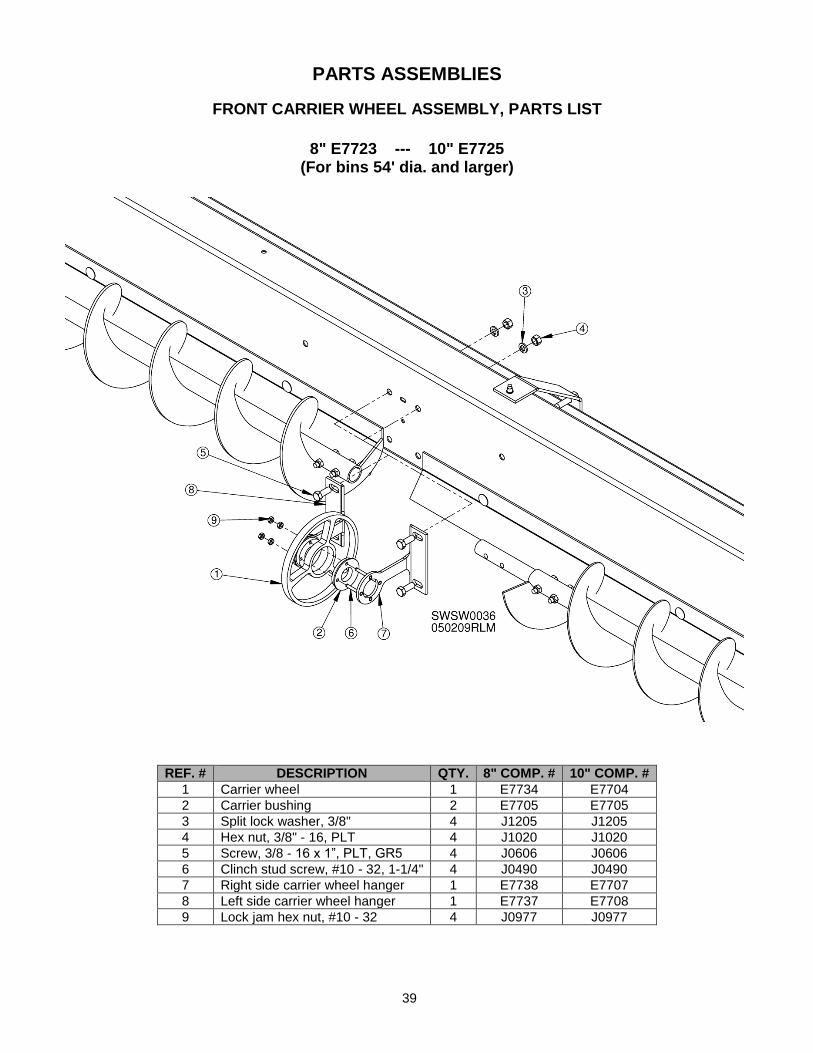
Image 5 – Conduit mounted on sweep backboard
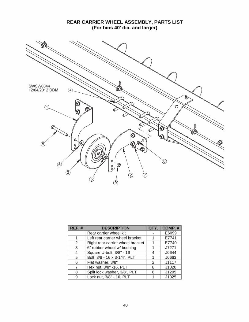
Image 6 – Welded
cable
CLUSTER BUSTER INSTALLATION
OVERVIEW: Obstructions to free-flowing grain may occur in bins due to excess moisture, freezing, build-up of fines and/or crusting. They sometimes prevent grain from flowing into sumps. The Cluster Buster uses an approach similar to a drain snake. A cable is spun above the sump, breaking up obstruction so grain will flow freely. This device provides a safe way to remove obstructions. It is operated from outside, eliminating need to enter bin.
Cluster Buster kits are available for bins 15’ to 61’ 10” in diameter. Kit E7975 is for sweeps in bins with a 6” or 8” diameter unload tube. Kit E7976 is for sweeps in bins with a 10” diameter unload tube. Installation process is same for both kits.
WARNING: Lock out power to bin before entering. Failure to do so could result in accidental activation of augers. Entanglement in an auger will result in death or
serious injury.
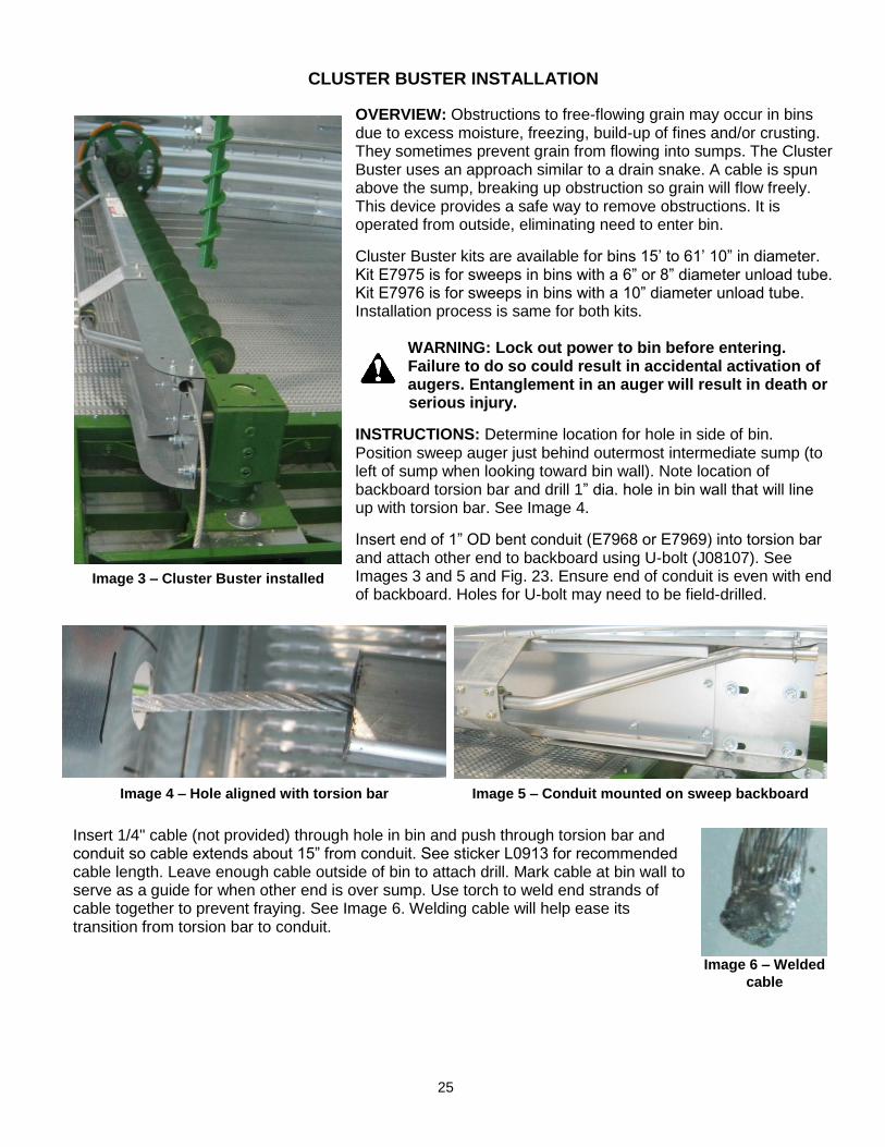
INSTRUCTIONS: Determine location for hole in side of bin. Position sweep auger just behind outermost intermediate sump (to left of sump when looking toward bin wall). Note location of backboard torsion bar and drill 1” dia. hole in bin wall that will line up with torsion bar. See Image 4.
Insert end of 1” OD bent conduit (E7968 or E7969) into torsion bar and attach other end to backboard using U-bolt (J08107). See Images 3 and 5 and Fig. 23. Ensure end of conduit is even with end of backboard. Holes for U-bolt may need to be field-drilled.
Insert 1/4" cable (not provided) through hole in bin and push through torsion bar and conduit so cable extends about 15” from conduit. See sticker L0913 for recommended cable length. Leave enough cable outside of bin to attach drill. Mark cable at bin wall to serve as a guide for when other end is over sump. Use torch to weld end strands of cable together to prevent fraying. See Image 6. Welding cable will help ease its transition from torsion bar to conduit.
Image 4 – Hole aligned with torsion bar

26
Image 9 – Rod hanging
inside of bin door
Remove cable from bin and insert rod through bin wall hole and into torsion bar. See Image 7. Press down on handle as shown in Image 8 to seal rubber grommet in hole. If seal is not tight, remove rod and turn rubber grommet counterclockwise while holding handle stationary to increase grommet diameter. Reinsert and check seal again. Repeat as needed.
Affix Cluster Buster operation sticker to inside of bin door near bolt where rod will hang when not in use.
TO OPERATE: From outside of bin, remove alignment rod and insert 1/4" cable through torsion bar and conduit. Push cable until it comes into contact with grain over sump.
Attach variable-speed drill to cable and turn drill on. Push spinning cable in and out until clog is broken up and grain is moving. NOTE: If cable does not turn when drill is activated, pull back slightly.
NOTICE: Before engaging sweep, make sure neither cable nor rod is in torsion bar.
When bin is empty, line up torsion bar with hole in bin wall. Slide rod into torsion bar from outside of bin and snap down handle to plug hole.
ITEM # DESCRIPTION QTY. COMP. #
1 Conduit for 6” or 8” Sweepway 1 E7968
2 Conduit for 10” Sweepway 1 E7969
3 U-bolt 1 J08107
4 Flat washer, 1/4" 2 J1105
5 Nut, 1/4” – 20 2 J0992
6 Alignment rod 1 E7985
7 Sticker 1 L0913
Image 8 – Rod/plug
handle outside of bin
Fig. 23 & Table 9
Image 7 – Alignment rod in torsion bar

27
SWEEPWAY POWERHEAD OPTIONS
See drawing and table on page 77 to guide installation of powerhead belt shield.
Horizontal with Single Motor Drive To aid in part identification during assembly, please refer to drawing and parts list on pages 44-45. 1. Slide connector sleeve onto unloading tube and loosely attach with 3/8 x 3" bolts, lock washers and
nuts. See pages 34-36 for instructions on installation of sump openers. 2. Remove safety shield sections (6, 8) and brackets (7) from powerhead assembly. Slide powerhead tube
into connector sleeve so unload auger shaft protrudes through flange bearing (9). Slide powerhead on completely so that it contacts unloading tube.
3. Rotate powerhead assembly to level position and tighten bolts on connector sleeve. 4. Slide locking collar (26) over auger shaft protruding from unloading tube and lock onto flange bearing.
Tighten setscrew on locking collar. 5. Mount 3.4" motor pulley onto motor shaft. Secure with key and setscrew. 6. Mount motor onto motor mount plate (4) with 3/8 x 1-1/2" bolts, nuts, lock washers and flat washers. 7. Re-attach brackets (7) and inner shield (8). 8. Attach pulley (25) to shaft extending from unload tube. Place 1/4" key (27) in slot on pulley and align
with motor pulley. Tighten setscrew. 9. Place belts (28) on pulleys. Tension may be adjusted by tightening bolt on bottom motor mount plate. See belt-adjusting instructions on page 33. 10. Place outer safety shield (6) over pulley and tighten bolts. KEEP SHIELD IN PLACE AT ALL TIMES!

28
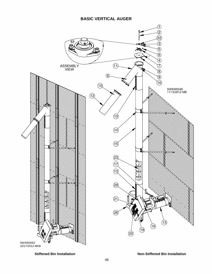
Basic Vertical Auger
To aid in part identification during assembly, please refer to drawings and parts list on pages 46-47. 1. Slide connector sleeve (13) halfway onto unloading tube. Loosely bolt with 3/8 x 3” bolts, lock washers
and nuts. See pages 34-36 for instructions on installation of sump openers. 2. Remove safety shield assembly from vertical auger boot. 3. Slide boot into sleeve (13) positioned on under-bin unloading tube so it contacts under-bin unloading
tube. Slide unloading auger shaft through flange bearing of boot while sliding tube together. Boot should be tight against under-bin unload tube. Rotate boot to right for assembly of vertical auger.
4. Slide second connector sleeve (13) halfway up vertical tube of boot. Loosely bolt in place with 3/8 x 3”
bolts, nuts and lock washers. 5. Slide vertical auger flighting (23) (double flighting at bottom) through boot so that bottom shaft extends
through bearing on bottom of boot. 6. Slide tube (15) over flighting into second connector sleeve so that tube contacts boot. Tighten connector
sleeve. 7. Attach third connector sleeve (13) to top half of tube (15). Loosely bolt in place. 8. Slide top spout (11) over flighting while sliding top auger shaft (2) through top bearing (4) into connector
sleeve so that top spout contacts tube. Rotate spout to desired unloading direction and tighten connector sleeve.
9. Place locking collar (22) over top shaft (2). Drive 5/16 x 1-3/4” rollpin (1) through hole in shaft just above
bearing and collar. Check to be sure rollpin rests against locking collar. Lock locking collar on flange bearing and tighten setscrew on locking collar.
10. Slide second locking collar onto shaft protruding from bearing end plate (Not shown) at bottom of
vertical auger and lock in place on flange bearing. Tighten setscrew. 11. Bolt 2-1/2' truck spout (12) onto top spout (11) using 3/8 x 1-1/2" bolts, nuts and lock washers. 12. Using crane, raise vertical auger into position. Provide temporary blocking under boot. Clamp support
bracket(s) around vertical auger. 13. Tighten bottom, horizontal connector sleeve. 14. Adjust threaded support jack bolt on boot to carry load of vertical auger. Remove temporary blocking
under auger. Check to see that tube and auger are aligned. 15. Using existing bin bolts, attach support brackets (14) to bin wall about 10’ up on vertical tube. If bin has
outside stiffeners, attach brackets to stiffeners (holes may need to be drilled). Adjust and secure legs of support brackets.
16. Slide locking collar over unloading shaft from horizontal auger. Lock in place on flange bearing. Tighten
setscrew. 17. Ensure all safety shields are in place and bolts are tight. NOTE: Safety shield brackets and inner shields
must be installed before pulleys.

29
Two Motor Drive (Standard Equipment)
To aid in part identification during assembly, please refer to drawing and parts list on pages 48-49. 1. Follow steps 1-17 in Basic Vertical Auger Assembly Instructions. 2. Mount motor (motor and motor pulley not included) onto horizontal motor mount using four 3/8 x 1-1/2"
bolts, lock washers, flat washers and nuts. Motor uses 3.4" motor pulley. 3. Reinstall brackets and inner shield section. 4. Mount large pulley onto horizontal shaft. Place 1/4" key in slot of pulley. Align pulley with motor pulley.
Tighten setscrews. 5. Install belts provided and tighten to proper tension by adjusting bolt under horizontal motor mount. See
belt-adjusting instructions on page 33. 6. Mount 3.4" motor pulley onto vertical motor. Mount motor to vertical motor mount plate, using four 3/8 x
1-1/2" bolts, nuts, washers and flat washers. 7. Mount 9" pulley onto bottom vertical shaft. Place 1/4" key in slot of pulley. Align with motor pulley and
tighten setscrews. 8. Install belt(s) onto pulleys and adjust to proper tension. See belt-adjusting instructions on page 33. 9. Ensure all safety shields are in place and bolts are tight.
One Motor Drive (Optional Equipment)
To aid in part identification during assembly, please refer to parts list and drawing on pages 49-50.
1. Follow steps 1-17 in Basic Vertical Auger Assembly Instructions. 2. Slide large pulley (35) onto shaft extending from horizontal unload tube with hub side of pulley out. Place
1/4" key (36) in slot on pulley. 3. Slide 50B15 sprocket (62) on shaft protruding from horizontal unload tube with hub side away from
pulley. 4. Slide 50B15 sprockets (56) on each shaft of gearbox and on bottom shaft of vertical auger. Place 1/4"
key in slots of all sprockets and align. Tighten setscrews. 5. Place short #50 chain and connector link on sprocket on bottom of gearbox and sprocket on bottom of
vertical auger. Chain can be tightened by adjusting gearbox mounting bolts. Align. 6. Mount motor onto mounting plate (11) with 3/8 x 1-1/4" bolts, nuts, washers, and flat washers. Mount 3.4"
motor pulley. Align pulleys and tighten setscrews. Place belts (39) on pulleys and adjust tension by adjusting under motor mount plate. See belt-adjusting instructions on page 33.
7. Place long #60 chain and connector link on sprocket on front of gearbox and on sprocket on end of
horizontal unload tube. Adjust tension by raising or lowering idler sprocket (64). Align. 8. Ensure all safety shields are in place and bolts are tight.

30
Top Drive
To aid in part identification during assembly, please refer to drawings and parts list on pages 52-53.
1. Slide first of three connector sleeves (40) halfway onto horizontal unloading tube. Loosely bolt connector sleeve with 3/8 x 3" bolts, nuts and lock washers.
2. Remove safety shields (48, 47) and shield brackets (46) from vertical auger boot.
3. Slide boot into sleeve (40), positioning on unloading tube so it contacts under-bin unload auger. Slide unloadingauger shaft through flange bearing of boot while sliding tube together. Boot should be tight against under-bin unload tube. Rotate boot to right for assembly of vertical auger.
4. Slide second connector sleeve halfway up vertical tube of boot. Loosely bolt in place with 3/8 x 3" bolts, nuts and lock washers.
5. Slide vertical flighting (double flighting at bottom) through boot so that bottom shaft extends through bearing on bottom of boot.
6. Slide tube (39) over flighting into second connector sleeve so tube contacts boot. Tighten connector sleeve.
7. Attach third connector sleeve (40) to top half of tube in same manner as previous connector sleeves. Loosely bolt in place.
8. Slide top spout (1) over flighting while sliding auger shaft through top bearing (4) into connector sleeve so that top spout is against tube. Rotate spout to desired unloading direction and tighten third connector sleeve.
9. Place locking collar (5) over top shaft (31). Add spacer (37). Mount pulley (9) on shaft. Drive 5/16 x 1-3/4" rollpin (11) through hole in shaft just above pulley. Check to be sure rollpin rests against pulley. Lock locking collar in place on flange bearing (4). Tighten setscrew.
10. Slide second locking collar (5) onto shaft protruding from bottom bearing end plate (Not shown) of vertical auger and lock in place on flange bearing. Tighten setscrew.
11. Bolt 2-1/2’ truck spout (43) onto top spout using 3/8 x 1-1/2" bolts, nuts and lock washers.
12. Using existing bin bolts, attach support bracket (42) to bin wall about 10' up on vertical tube.
13. Using crane, raise vertical auger into position. Provide temporary blocking under boot. Clamp support bracket around vertical auger.
14. Tighten bottom, horizontal connector sleeve.
15. Adjust threaded support jack bolt on boot to carry load of vertical auger. Remove temporary blocking under auger. Check to see that tube and auger are aligned.
16. Adjust and secure legs of support bracket.
17. Slide third locking collar over unloading shaft from bearing. Tighten setscrew.
18. Remove motor mount and bolt to motor using four 3/8 x 1-1/2" bolts, flat washers and lock washers. Re-attach motor mount.
19. Re-attach safety shield brackets and inner shields.
20. Align pulley (9) with motor pulley. Insert 1/4" key in key slot and tighten setscrew.
21. Place belts (23) onto pulleys and tighten using motor mount adjustment bolt. Belt tension should be as low as possible without allowing belts to slip. See belt-adjusting instructions on page 33.
22. Recheck belt tension before operation. Replace outer section of safety shields. NEVER OPERATE UNIT WITHOUT SAFETY SHIELDS SECURELY IN PLACE. Make sure all safety decals have been installed and are legible. See safety section for correct locations and descriptions of safety decals.

31
Fig. 27
Incline
To aid in part identification during assembly, please refer to drawings and parts list on pages 54-55.
NOTE: Instructions below use part reference numbers for 25° incline. Follow same steps to install 20° incline. Reference numbers will be different. See pages 56-57 for drawings and parts list for 20° incline.
1. Remove motor mount (6), shield sections (13, 14) and shield brackets (15) from top of incline.
2. Remove bolts holding tube mount (10) to incline tube (1). Connect one end of each support chain to each side of tube mount. See Fig. 24. Tighten bolts.
3. Remove two bin bolts spaced equidistant from unload tube (“A” = 80-100") along seam between second and third rings of bin sheets (“B” = 60-80"). See Fig. 26.
4. Remove shaft and corn flipper from end of unload auger. NOTE: Keep fasteners. They will be used later. Weld a 1' piece of flighting to unload flighting. See Fig. 27.
5. Slide connector sleeve (19) halfway over end of unload tube. 6. Slide adapter sleeve (17) into open end of connector sleeve.
7. Loosely install six 3/8 x 3" bolts (29) and nuts (34) on connector sleeve. 8. Rotate adapter sleeve to match hole pattern of angle ring on incline (1). 9. Tighten all bolts on connector sleeve.
Fig. 24
Fig. 25
INSTALL EYEBOLT WITH ONE NUT COMPLETELY THREADED BEFORE PUTTING IN BIN WALL. START SECOND NUT ON EYEBOLT, LEAVING ROOM TO TAKE UP SLACK IN CHAIN
Fig. 26

32
10. Attach adapter plate (16) to adapter sleeve using 5/16 x 1-1/4" bolts (26), flat washers (39), lock
washers (40) and nuts (33). 11. After sliding horizontal unload flighting out to attach to incline, temporarily support incline. Slide
horizontal shaft (3) into horizontal flighting and bolt into place using two 7/16 x 2” bolts. Use bolts from step 4. Slide unload auger back into under-bin tube along with incline tube and flighting. If installing with a powersweep, make sure unload auger slides onto drive shaft in center sump.
12. Bolt incline (1) to adapter plate (16) using 5/16 x 1-1/4" bolts (26), flat washers (39), lock washers
(40), and nuts (33). 13. Attach chain to eyebolts and tighten nuts on inside of bin to tighten chains. See Fig. 25. 14. Bolt motor to motor mount (6) using four 3/8 x 1-1/2" bolts, flat washers, and lock washers. Re-attach
motor mount to tube mount (10). 15. Re-attach shield brackets (15) and inner shield (14) to tube mount (10). 16. Attach 14" pulley (23) to power shaft (4) extending from top of powerhead. Align pulley with motor
pulley. Insert 1/4" key (18) in key slot and tighten setscrew in pulley (23). 17. Place belts (22) onto pulleys and tighten using motor mount adjustment bolt (32). Belt tension should
be as low as possible without allowing belts to slip. See belt-adjusting instructions on page 33. 18. Recheck belt tension before operation. Re-attach outer section of safety shield (13). NEVER
OPERATE UNIT WITHOUT SAFETY SHIELDS SECURELY IN PLACE. Make sure all safety decals have been installed and are legible. See safety section in this manual for correct locations and descriptions of safety decals.

33
ADJUSTING BELT TENSION
Place belt(s) in sheave grooves and tighten by adjusting motor mount. Follow these steps to tension belt.
1. Measure span length. See Fig. 28. 2. At center of span, apply enough force to deflect belt 1/64” for every 1” of belt span. If span is 32”,
deflection amount should be 32/64”, or 1/2”. 3. Use Table 10 to determine amount of force to apply to gauge proper deflection per belt.
Table 10 – Belt deflection settings for Bestorq belts
Sukup products use belts made by Bestorq. Sukup recommends using a Bestorq tension meter to measure belt deflection. Go to www.bestorq.com or call (402) 423-3077 for more information.
After adjusting tension to desired level by adjusting motor mount, remove any foreign material from inside of belt guard. Check that all fasteners are tightly secured. Close and latch belt guard.
IMPORTANT: Check and adjust belt tension after first five (5) and 24 hours of operation, then during regular maintenance (at least twice yearly).
Belt Cross
Section
Smallest Pulley
Diameter Range
RPM Range
Belt Deflection Setting
Deflection = 1/64 of belt span Uncogged Single V-Belts & Uncogged Banded V-Belts
Cogged V-Belts & Cogged Banded V-Belts
Used Belt New Belt Used Belt New Belt
A, AX
3.0 – 3.6” 1,000 – 2,500 3.6 5.4 4.0 6.0
2,501 – 4,000 2.8 4.1 3.3 4.9
3.8 – 4.8” 1,000 – 2,500 4.4 6.6 4.9 7.3
2,501 – 4,000 3.7 5.7 4.3 6.4
5.0 – 7.0” 1,000 – 2,500 5.3 7.8 5.7 9.2
2,501 – 4,000 4.6 6.8 5.1 7.6
B, BX
3.4 – 4.2” 860 – 2,500 --- --- 4.8 7.2
2,501 – 4,000 --- --- 4.1 6.2
4.4 – 5.6” 860 – 2,500 5.2 7.9 7.1 10.5
2,501 – 4,000 4.5 6.6 7.1 9.1
5.8 – 8.6” 860 – 2,500 6.2 9.4 8.4 12.4
2,501 – 4,000 6.0 6.8 7.3 10.7
5V, 5VX
4.4 – 6.7”
500 – 1,749 --- --- 10 15.2
1,750 – 3,000 --- --- 8.9 13.2
3001 – 4000 --- --- 5.6 8.5
7.1 – 10.9” 500 – 1,740 12.6 18.9 14.8 22.1
1,741 – 3,000 11.2 16.5 13.7 20.1
11.8 – 16.0” 500 – 1,740 15.5 23.4 17.1 25.5
1,741 – 3,000 14.5 21.8 16.8 25
Fig. 28 – Adjusting
belt tension

34
PULL ROD OPENER FOR 6” SWEEPWAY
REF. # DESCRIPTION QTY. 6" COMP. #
Complete pull rod opener assembly 1 E5432
1 Stationary bar 1 E5884
2 Center sump weldment L handle 1 E5889
3 Intermediate sump weldment L handle 1 E5888
4 Pivoting arm 1 E5885
5 Bolt, 3/8 - 16 x 3”, PLT, GR5, tap 6 J0660
6 Hex nut, 3/8” -16, PLT 12 J1020
Installation instructions: 1. Bolt bar (1) to connector sleeve using double nuts as shown in Fig. 29. 2. Line up last hole on bar with hole in intermediate sump handle (3) with sumps fully closed. Connector
sleeve can be slid onto tube for proper alignment. 3. Slide lever arm (4) through hole in center sump handle (2) and through hole in bar (1). Pull arm away
from bin to open sumps and push arm toward bin to close sumps. NOTE: Always open and unload from center sump first. Never open intermediate sumps until grain stops flowing from center sump.
Fig. 29

35
RACK & PINION OPENER FOR 8” SWEEPWAY
REF. # DESCRIPTION QTY. 8" COMP. #
Complete rack & pinion opener assembly 1 E5443
1 Center sump connector weldment 1 E5914
2 Rack & pinion opener assy., 8" 1 E5919
3 Opener handle 1 E5967
4 Intermediate sump connector weldment 1 E5998
5 Quick-release pin, 3/8 x 1" 2 J1554
6 Rubber cap, 1" 1 J2232
7 Screw, 3/8 - 16 x 3”, PLT, GR5 6 J0660
8 Hex nut, 3/8” - 16, PLT 6 J1020
Installation instructions:
1. Attach intermediate sump and center sump connectors, (4) and (1), to proper pull rod. 2. Bolt rack and pinion opener assembly (2) to sleeve connector using three bolts closest to bin wall. 3. Connect center sump connector (1) to opener using 3/8" x 1" quick release pin (5). 4. Attach handle (3) to opener and open sump gates by rotating handle clockwise. Sump gates should open and close fully.
Fig. 30

36
RACK & PINION OPENER FOR 10” SWEEPWAY
REF. # DESCRIPTION QTY. 10" COMP. #
Complete rack & pinion opener assembly 1 E5444
1 Rack & pinion opener assembly, 10" 1 E5969
2 Intermediate sump connector weldment 1 E5998
3 Center sump connector weldment 1 E5997
4 Quick-release pin, 3/8 x 1" 2 J1554
5 Opener handle 1 E5967
6 Screw, 3/8 - 16 x 3”, PLT, GR5 6 J0660
7 Hex nut, 3/8” - 16, PLT 6 J1020
8 Rubber cap, 1" 1 J2232
Installation instructions:
1. Attach intermediate sump and center sump connectors, (2) and (3), to proper pull rod. 2. Bolt rack and pinion opener assembly (1) to sleeve connector using three bolts closest to bin wall. 3. Connect center sump connector (3) to opener using 3/8 x 1" quick-release pin (4). 4. Attach handle (5) to opener and open sump gates by rotating handle clockwise. Sump gates should
open and close fully.
Fig. 31

37
OPERATING INSTRUCTIONS Standard Sukup grain bins are designed with anchors that allow sweeping of entire diameter of bin in one stage. However, older Sukup bins 72’ dia. and larger that do not have two anchors per stiffener should be swept in multiple stages beginning with inner section of floor, and then outer section after sweep extension is added. Additional anchor brackets can be purchased from Sukup Manufacturing Co. and retrofitted to enable single-stage sweeping.
For single-stage sweeping of Sukup bins 54’ to 105’ in diameter, bin must have 1” Grade 5 anchor bolts (17” deep for “Inverted T” foundation, or deep into stemwall ring rebar zone for “T-Cap”), with a minimum of 7-1/2” from anchor to outside edge of stemwall. Check bin anchor specifications prior to using sweep.
Bins by other manufacturers that are 60’ dia. or less may be swept in one stage provided anchors have been inspected and found suitable for single-stage sweeping. (Contact bin manufacturer for further information). For larger bins by others, sweep in multiple stages: Use only inner section of sweep on first pass, making one revolution around bin, then connect outer section and sweep remainder of bin.
Single-Stage Sweeping
DANGER: KEEP AWAY when auger is running. Entanglement with rotating auger will cause death or serious injury.
NOTICE: If bin is equipped with a Cluster Buster, ensure neither rod nor cable is in torsion bar. If bin is equipped with a sidedraw, do not use at same time sumps are being used to unload grain.
1. Start horizontal (and vertical if applicable) unload auger(s). Open center sump. Unload grain from center sump until gravity flow stops.
2. Open intermediate sumps, allowing additional gravity flow into unloading auger. If bin has an Independent Intermediate Sump, open it by pulling rod shown in Fig. 32.
3. When grain flow stops, shut off power to system. Engage sweep auger by pulling clutch rod. NOTICE: Power must be shut off before engaging sweep auger to prevent damage to clutch
assembly.
Fig. 32

38
4. Turn on power. Center sump slide gate must remain FULLY open and sweep stop must be deployed while sweep auger is operating. See Fig. 19 and Image 2 to position sweep stop. Remove remaining grain, making sure to reposition stop before each revolution.
DANGER: When bin is nearly empty, sweep auger will travel at an increasingly fast speed. Keep away from auger to avoid entanglement, which will result in death or serious injury.
5. Close sumps, place sweep just behind intermediate sumps and make sure sweep stop is retracted before re-filling bin.
NOTE: If a slower flow of grain is desired, (e.g., grinding) a larger driven pulley (12” comes standard) should be used on unload auger. (14” pulley available from Sukup Manufacturing Co.)
NOTE: If grain starts to pile up in center of bin when power sweep is engaged and center sump is fully open, sweep may need to be slowed down. To do so, sprocket on bottom gearbox should be changed. On 8” unit, replace standard 15-tooth sprocket with a 12-tooth sprocket (Comp. # J1660). On 10” unit, replace standard 20-tooth sprocket with an 18-tooth sprocket (Comp. # J1675). NOTE: When changing sprockets, chain links may need to be removed.
Multiple-Stage Sweeping
Follow steps 1-3 on previous page, observing all safety precautions.
4. Turn on power. Allow sweep to make one full revolution. Center sump slide gate must remain FULLY open while sweep auger is operating.
DANGER: When inner area of bin is nearly empty, sweep auger will travel at an increasingly fast speed. Keep away from auger to avoid entanglement, which will result in death or serious injury.
5. After inner area of bin has been swept, shut off and lock out power to entire system before adding outer section of sweep.
6. Unbolt sweep wheel assembly from inner section of sweep. Line up outer section of sweep with inner
section. Connect backboards by attaching splice stiffener and splice brace to backboards and bolting together. See Fig. 22. Connect auger sections and attach drive wheel to outer section. See instructions on page 21.
7. Make sure sweep stop is extended outward. See Fig. 19 and Image 2 to position sweep stop.
8. Exit bin, turn power back on and unload remainder of grain using both sections of sweep.
9. Before filling bin again, remove outer section of auger and backboard. Bolt sweep wheel back onto inner section of backboard. Outer section can be left in bin, positioned so it will not interfere with next use of inner section of sweep. Position inner section just behind intermediate sumps before refilling bin.
See notes above for slowing flow of grain in unload and/or slowing speed of sweep.
39
PARTS ASSEMBLIES
FRONT CARRIER WHEEL ASSEMBLY, PARTS LIST
8" E7723 --- 10" E7725
(For bins 54' dia. and larger)
REF. # DESCRIPTION QTY. 8" COMP. # 10" COMP. #
1 Carrier wheel 1 E7734 E7704
2 Carrier bushing 2 E7705 E7705
3 Split lock washer, 3/8" 4 J1205 J1205
4 Hex nut, 3/8" - 16, PLT 4 J1020 J1020
5 Screw, 3/8 - 16 x 1”, PLT, GR5 4 J0606 J0606
6 Clinch stud screw, #10 - 32, 1-1/4" 4 J0490 J0490
7 Right side carrier wheel hanger 1 E7738 E7707
8 Left side carrier wheel hanger 1 E7737 E7708
9 Lock jam hex nut, #10 - 32 4 J0977 J0977
40
REAR CARRIER WHEEL ASSEMBLY, PARTS LIST (For bins 40' dia. and larger)
REF. # DESCRIPTION QTY. COMP. #
Rear carrier wheel kit - E6099
1 Left rear carrier wheel bracket 1 E7741
2 Right rear carrier wheel bracket 1 E7740
3 6” rubber wheel w/ bushing 1 J7271
4 Square U-bolt, 3/8" - 16 4 J0644
5 Bolt, 3/8 - 16 x 3-1/4", PLT 1 J0663
6 Flat washer, 3/8" 2 J1117
7 Hex nut, 3/8" -16, PLT 8 J1020
8 Split lock washer, 3/8", PLT 8 J1205
9 Lock nut, 3/8" - 16, PLT 1 J1025

41
SPLICE - SPLIT BACKBOARD, PARTS LIST
REF. # DESCRIPTION QTY. 8" COMP. # 10" COMP. #
1 Splice stiffener 1 E7029 E7027
2 Splice brace 1 E7028 E7026
3 Flighting ---- E81-- E81--
4 Bushing extension support 1 E60811 E60821
5 Support weldment w/ brass bushing 1 E6065 E6065
6 Connecting shaft, 1” x 8-1/2" 1 E6704-03 E6704-03
7 Screw, 3/8 - 16 x 1”, PLT, GR5 23 J0606 J0606
8 Lock washer, 3/8", PLT 23 J1205 J1205
9 Hex nut, 3/8" - 16, PLT 15 J1020 J1020
10 Screw, 5/16 x 1-3/4”, PLT, GR5 4 J0570 J0570
11 Lock nut, 5/16” - 18, PLT 4 J1010 J1010

42
TUBE, AUGERS & SWEEP 6", 8” & 10"

43
TUBE, AUGERS & SWEEP, 6", 8” & 10", PARTS LIST REF. # DESCRIPTION QTY. 6" COMP. # 8" COMP. # 10" COMP. #
1 Extension bracket 1 E6976 E6977 E6979
2 Decal, DANGER, Keep Away when … 1 L03061 L03061 L03061
3 Sweep auger * (Need bin dia., pitch, length) ** ---- ---- ----
4 Support bushing ** E6065 E6065 E6065
5 Reduction wheel 1 E6094 E6092 E6093
5A 16-to-1 reduction drive wheel assembly *** 1 ---- E7338 E7340
6 Unload auger flight assembly ** E64-- E64-- E64--
7 Center sump gate pull rod * 1 E61-- E61-- E61--
8 Unload tube * 1 ----- ----- -----
9 Clutch rod support clamp 1 E5314 E5364 E53162
10 Top half intermediate sump ** E5410 E5410 E5411
11 Intermediate slide gate ** E5409 E5409 E5409
12 Intermediate sump gate pull rod * 1 E62-- E62-- E62--
13 Tek screw, #10 - 16 x 1-1/2" ** J0502 J0502 J0502
14 Bin collar w/ clutch lock assy. 1 E5405 E5406 E5362
15 Intermediate sump rod handle, 7/8" 1 E5404 E5404 E5404
16 Auger shaft, 1998 1 E90061 E54151 E54142
17 Spacer, 6 & 8", 1/2” ID x 1"; 10", 1/2" ID x 1-3/8" 4 E6014 E6014 E6013
18 Flat washer, 7/16" 4 J1120 J1120 J1120
19 Hex nut, 7/16” x 14 4 J1035 J1035 J1035
20 Stud bolt, 7/16 – 14 x 2-3/4", PLT, GR5 4 J07211 J07211 J07211
21 Lock nut, 5/16” - 18 ** J1010 J1010 J1010
22 Split lock washer, 3/8" ** J1205 J1205 J1205
23 Hex nut, 3/8 - 16, PLT ** J1020 J1020 J1020
24 Bolt, 5/16 - 18 x 1-3/4", GR5 ** J0570 J0570 J0570
25 Bolt, 3/8 - 16 x 1", GR5 ** J0606 J0606 J0606
26 Threaded bolt, 3/8 - 16 x 1-3/4", GR5, FL ** J0640 J0640 J0640
27 Bolt, 5/16 - 18 x 3/4", GR5 ** J0520 J0520 J0520
28 Hex nut, 5/16” - 18, PLT ** J1002 J1002 J1002
29 Corn flipper only 2 E5689 E5689 E5689
30 Lock nut, 5/16” - 18 ** J1010 ---- ----
Lock nut, 7/16” - 14 ** ---- J1034 J1034
Bolt, 5/16 - 18 x 2”, GR5 ** J0585 ---- ----
31 Bolt, 7/16 - 14 x 2-1/2" ** ---- J0720 ----
Bolt, 7/16 - 14 x 3" ** ---- ---- J0722
32 Shaft collar, 7/8" ** J1330 J1330 J1330
33 Clutch pull rod * 1 E61-- E61-- E61--
34 Picker pin, 1/2 x 1-1/2" 2 J1550 J1550 J1550
35 Shaft collar, 1/2" 1 J1320 J1320 J1320
36 Cotter, 1/8 x 1" 1 J1420 J1420 J1420
37 Machine bushing, 1/2" x 18ga 3 J1250 J1250 J1250
38 Pawl spring 1 J2360 J2360 J2360
39 Clutch latch 1 E5408 E5408 E5408
40 Connecting shaft ** E6704-03 E6704-03 E6704-03
41 Split lock washer, 7/16, PLT 4 J1210 J1210 J1210
42 Assembly bushing support ** E6089 E6090 E6091
43 Galvanized backboard scraper, 36" ** E8430 E8430 E8430
Galvanized backboard scraper, 18" ** E8431 E8431 E8431
44 Carriage bolt, 3/8 x 1” ** J06064 J06064 J06064
45 Picker pin, 3/8 x 1-1/2” ** J1541 J1541 J1541
46 Hairpin clip, .09 x 2 ** J5410 J5410 J5410
47 Flat washer, 3/8” ** J1117 J1117 J1117
48 Carrier wheel, 8" and 10" assembly, 2005 ** ---- E7734 E7725
49 Bolt, 3/8 - 16 x 1-1/4” ** J0616 J0616 J0616
50 Independent intermediate sump 1 ---- E7996 E7999
* Specify bin size ** Quantities may vary w/ bin size *** For use in bins 36’ dia. and larger

44
HORIZONTAL POWERHEAD MOTOR DRIVE

45
HORIZONTAL POWERHEAD MOTOR DRIVE PARTS LIST
REF.# DESCRIPTION QTY. 6” COMP. # 8” COMP. # 10” COMP. #
Powerhead w/ shield & bearing 1 E5600 E5601 E5602
HPH w/ bearing, shield, lg. motor mount. 1 ----- E5599 E5611
1 STD powerhead housing 1 E5567 E5568 E5569
2 6” bearing plate 1 E5676 ----- ----- 8” bearing plate 1 ----- E5776 -----
10” bearing plate 1 ----- ----- E5659
3 Nut, 3/8 – 16, PLT 8-12 J1020 J1020 J1020
4 Hinged motor mount, small 1 E5746 E5746 E5746
Hinged motor mount, large 1 ------ E5765 E5765
5 Small pivot rod 1 E5744 E5744 E5744
Large pivot rod 1 ------ E57441 E57441
6 Outer shield 1 E5973 E5973 E5973
7 Shield bracket 2 E9316 E9316 E5974
8 Inner shield 1 E5972 E5972 E5972
9
1” flange bearing w/ locking collar 2 J0003 ----- -----
1-1/4” flange bearing w/ locking collar 2 ----- J0010 J0010 Bearing spacer (Not shown) 1 E5791 E5792 E5792
10 Bearing bolt w/ tab 2 E5570 ----- -----
Bolt, 1/2 - 13 x 1-1/2”, PLT 2 ----- J0730 J0730
11 Split lock washer, 7/16”, PLT 2 J1210 ----- ----
Split lock washer, 1/2", PLT 2 ----- J1215 J1215
12 Nut, 7/16 - 14, PLT 2 J1035 ----- -----
Nut, 1/2" - 13, PLT 2 ----- J1040 J1040
13 Hairpin clip, .120 x 2.5 2 J5412 J5412 J5412
14 Tap bolt, 3/4 - 10 x 6”, PLT 1 J0824 J0824 J0824
15 Nut, 3/4 - 10, PLT 1 J1051 J1051 J1051
16 Machine bushing, 3/4 x 1-1/4", 14ga 1-20 J1260 J1260 J1260
17 Long spacer, 3/8" 1 E5739 E5739 E5739 Longer spacer, 2-7/16” 1 ------ E5740 E5740
18 Bolt, 3/8 – 16 x 1’, PLT 4-6 J0606 J0606 J0606
19 Split lock washer, 3/8”, PLT 4-6 J1205 J1205 J1205
20 Decal, Safe Operation 1 L0281 L0281 L0281
21 Bolt, 5/16 – 18 x 1”, PLT 8 J0527 J0527 J0527
22 Flat washer, 5/16”, PLT 4 J1111 J1111 J1111
23 Split lock washer, 5/16”, PLT 8 J1200 J1200 J1200
24 Screw, 3/16 – 18 x 1/2", PLT, SL 4 J0519 J0519 J0519
25
Pulley, 12 x 1”, single groove A-B 1 J0375 ----- -----
Pulley, 12 x 1”, DBL groove B 1 J0380 ----- -----
Pulley, 12 x 1-1/4”, DBL groove B 1 ----- J0385 -----
Pulley, 12 x 1-1/4”, triple groove B 1 ----- J0379* J0379* Pulley, 12 x 1-1/4”, single groove A-B 1 ----- J0388 -----
26 Locking collar, 1” 1 J0067 ----- -----
Locking collar, 1-1/4” 1 ----- J0068 J0068
27 Key, 1/4" x 2-1/2” 1 E5720 E5720 E5720
28 Belt, BX48 BX50 1-2 J0220 J0220 J0224
Belt, B52 “3 drive belt” 3 ------ ------- J0227
29 Decal, Do Not Enter Bin, Avoid Augers 1 L0258A L0258A L0258A
30 Decal, Keep Away From Moving Parts 1 L0284 L0284 L0284
*J0379 pulley requires J0410 bushing
46
BASIC VERTICAL AUGER
Stiffened Bin Installation Non-Stiffened Bin Installation
SWSW0052 10/17/2012 MKB

47
BASIC VERTICAL AUGER PARTS LIST
REF. # DESCRIPTION QTY. 6" COMP. # 8" COMP. # 10" COMP. #
1 Rollpin, 5/16" x 1-3/4" 1 J1495 J1495 J1495
2 Top shaft 1 E58091 E97711 E58243
3 Hex nut, 7/16" -14, PLT 2 J1035 ----- -----
Hex nut, 1/2" - 13, PLT 2 ----- J1040 J1040
4 1” flange bearing w/ lock collar 1 J0003 ------ ------
1-1/4" flange bearing, w/ lock collar 1 ------ J0010 J0010
5 Split lock washer, 7/16", PLT 2 J1210 J1210 -----
Split lock washer, 1/2", PLT 2 ----- ----- J1215
6 Bolt, 3/8 - 16 x 1", GR 5, PLT 12 J0606 J0606 -----
Bolt, 7/16" - 14 x 1", GR5, PLT 12 ----- ----- J0695
7 Bearing end plate 1 E5676 E5776 E5659
8 Bolt, 7/16 - 14 x 1.25" GR5, PLT 2 J0700 ----- -----
Bolt, 1/2 - 13 x 1.5", GR5, PLT 2 ----- J0730 J0730
9 Split lock washer, 3/8", PLT 2 J1205 J1205 -----
Split lock washer, 7/16", PLT 2 ----- ------ J1210
10 Hex nut, 3/8” - 16, PLT 12 J1020 J1020 -----
Hex nut, 7/16" – 14, PLT 12 ----- ----- J1035
11 Top outlet spout 1 E5812 E5813 E5785
12 2-1/2’ truck spout 1 E5814 E5815 E5787
13 Connector sleeve 3 E5423 E5424 E5425
14 30" support bracket (bipod) 2 E5800 E5801 E5786
15 12’ galvanized auger tube 1 E5842 E5843 E57842
16 Screw, 5/16 - 18 x 1/2”, PLT, SL 8 J0519 J0519 J0519
17 Rack & pinion opener 1 ----- E5919 E5969
18 Hex nut, 5/16” – 18, PLT (Not shown) 2 J1002 J1002 J1002
19 Decal, Keep Away from Moving Parts 1 L0284 L0284 L0284
20 Decal, Do Not Enter Bin, Keep clear of augers 1 L0258A L0258A L0258A
21 Decal, Safe Operation 1 L0281 L0281 L0281
22 Locking collar, 1” 1 J0067 ------ ------
Locking collar, 1-1/4” 1 ------ J0068 J0068
23 16' vertical auger w/ flinger & shafts (See page 80 for flighting, shafts & tubes)
1 E5846 E5847 E57833
24 Bottom shaft, w/ keyway (Not shown) 1 E58081 E9751 E58252
25 Decal, Shield Missing (Not shown) 1 L0271 L0271 L0271
26 Outer vertical shield 1 E5977 E5977 E5977
27 Inner vertical shield (Not shown) 1 E5976 E5976 E5976
28 Vertical shield bracket (Not shown) 2 E5978 E5978 E5978
29 Outer horizontal shield 1 E5973 E5973 E5973
30 Inner horizontal shield (Not shown) 1 E5972 E5972 E5972
31 Horizontal shield bracket (Not shown) 2 E9316 E9316 E5974
32 Screw, 5/16 – 18 x 1”, PLT, GR5 (Not shown) 6 J0527 J0527 J0527
33 Split lock washer, 5/16”, PLT (Not shown) 6 J1200 J1200 J1200
34 Flat washer, 5/16”, PLT, (Not shown) 6 J1111 J1111 J1111

48

49
Table applies to two-motor drive and one-motor drive units

50

51
CONNECTOR SLEEVE ASSEMBLY, PARTS LIST
REF. # DESCRIPTION QTY. 6” COMP. # 8” COMP. # 10” COMP. #
1
Connector sleeve, 6 x 18” 1 E5423 -- --
Connector sleeve, 8 x 18” 1 -- E5424 --
Connector sleeve, 10 x 18” 1 -- -- E5425
2 Screw, 3/8 -16 x 3”, PLT 6 J0660 J0660 J0660
3 Lock washer, 3/8”, PLT 6 J1205 J1205 J1205
4 Hex nut, 3/8 - 16, PLT 6 J1020 J1020 J1020
5
Shaft, 1” x 15-1/4”, w/ key 1 E90061 -- --
Shaft, 1-1/4 x 15-3/4”, w/ key 1 -- E54151 --
Shaft, 2 x 18”, w/ key 1 -- -- E54142
6
Lock nut, 5/16” - 18, PLT 2 J1010 -- --
Lock nut, 7/16” - 14, PLT 2 -- J1034 --
Lock nut, 1/2" - 13, PLT 2 -- -- J1042
7 Hex nut, 3/8” - 16, PLT, lock 2 J1025 J1025 J1025
8
Screw, 5/16 - 18 x 1-3/4”, PLT 1 J0570 -- --
Screw, 7/16 - 14 x 2”, PLT 1 -- J0718 --
Screw, 1/2 - 13 x 3”, PLT 1 -- -- J0750
9
Flinger, 3 x 5-3/8, 6” 2 E5416 -- --
Flinger, 5 x 6-1/2, 8” 2 -- E54161 --
Flinger, 7 x 7-1/2, 10” 2 -- -- E5689
10
Screw, 3/8 - 16 x 1”, PLT 2 J0606 -- --
Screw, 3/8 - 16 x 1”, PLT 2 -- J0606 --
Screw, 3/8 - 16 x 1-3/4”, PLT 2 -- -- J0645
11 Flat washer, 3/8”, PLT 2 -- J1117 --
12
Screw, 5/16 - 18 x 2”, PLT 1 J0585 -- --
Screw, 7/16 - 14 x 2-1/2”, PLT 1 -- J0720 --
Screw, 1/2 - 13 x 3-1/2”, PLT 1 -- -- J0754

52
TOP DRIVE ASSEMBLY

53
TOP DRIVE ASSEMBLY PARTS LIST
REF. # DESCRIPTION QTY. 6" COMP. # 8" COMP. # 10" COMP. #
1 Top power housing spout 1 E5929 E5933 E57851
2 Bearing plate 1 E5676 E5776 E5659
3 Hex nut, 3/8" - 16, PLT 4 J1020 J1020 -----
Hex nut, 7/16" - 14, PLT 4 ----- ----- J1035
4 Flange bearing 2 J0003 J0010 J0010
5 Locking collar 3 J0067 J0068 J0068
6 Bolt, 7/16 - 14 x 1-1/4", GR5, PLT 2 J0700 ----- -----
Bolt, 1/2 - 13 x 1-1//2", GR5, PLT 2 ----- J0730 J0730
7 Split lock washer, 7/16", PLT 2 J1210 ----- -----
Split lock washer, 1/2", PLT 2 ----- J1215 J1215
8 Hex nut, 7/16" - 14, PLT 2 J1035 ----- -----
Hex nut, 1/2" - 13, PLT 2 ----- J1040 J1040
9 Pulley, 9" OD 2 groove 1 J0365 J0366 J0366
10 Bolt, 3/8 - 16 x 1", GR5, PLT 4 J0606 J0606 -----
Bolt, 7/16 - 14 x 1", GR5, PLT 4 ----- ----- J0695
11 Rollpin, 5/16 x 1-3/4”, PLT 1 J1495 J1495 J1495
12 Bolt, 3/4 - 10 x 6”, GR5, PLT 1 J0824 J0824 J0824
13 Hex nut, 3/4” – 10, PLT 1 J1051 J1051 J1051
14 Hinged motor mount, small 1 E5746 E5746 E5746
15 Pivot rod, small 1 E5744 E5744 E5744
16 Hairpin clip, .120 x 2.5 1 J5412 J5412 J5412
17 Flat washer, 3/4", PLT 2 J1130 J1130 J1130
18 Split lock washer, 3/8", PLT 4 J1205 J1205 -----
Split lock washer, 7/16", PLT 4 ----- ----- J1210
19 Split lock washer, 3/8", PLT 4 J1205 J1205 J1205
20 Hex nut, 3/8” - 16, GR5, PLT 5 J1020 J1020 J1020
21 Square key, 1/4 x 2-1/2" 1 E5720 E5720 E5721
22 Pulley, 3/2 P.D., 1-1/8 DBL, cast 1 J0317 J0317 J0317
23 Belt, BX42 (6 & 8") - BX46 (10") 2 J0200 J0200 J0215
24 Vertical shield bracket 2 E9316 E9316 E5974
25 Inner vertical shield 1 E5972 E5972 E5972
26 Bolt, 5/16 - 18 x 1”, GR5, PLT 8 J0527 J0527 J0527
27 Flat washer, 5/16", PLT 8 J1111 J1111 J1111
28 Split lock washer, 5/16" PLT 4 J1200 J1200 J1200
29 Screw, 5/16 – 18 x 1/2", PLT, SL 8 J0519 J0519 J0519
30 Outer vertical shield 1 E5973 E5973 E5973
31 Top power shaft 1 E58092 E54153 E58244
32 Decal, Do Not Enter Bin, Keep Clear of Augers 1 L0258A L0258A L0258A
33 Decal, Danger, Replace Missing Shield 2 L0271 L0271 L0271
34 Decal, Safe Operation 2 L0281 L0281 L0281
35 Decal, Keep Away From Moving Parts 2 L0284 L0284 L0284
36 Decal, Sukup logo (Not shown) 1 L0317 L0317 L0317
37 Top drive spacer 1 E57415 E57415 E57415
38 Rack & pinion opener 1 ----- E5919 E5969
39 Auger tube for 16' vertical 1 E5842 E5843 E57842
40 Connector sleeve 3 E5423 E5424 E5425
41 16’ vert. auger w/ flinger & shafts (Not shown) 1 F4750 E58471 E57836
42 Support bracket, 30" (bipod) 1 E5800 E5801 E5786
43 Truck spout, 2-1/2' 1 E5814 E5815 E5787
44 Bolt, 3/8 - 16 x 1”, GR5 6-8 J0606 J0606 J0606
45 Hex nut, 3/8” - 16 6-8 J1020 J1020 J1020
46 Horizontal shield bracket (Not shown) 2 E9316 E9316 E5974
47 Inner horizontal shield (Not shown) 1 E5972 E5972 E5972
48 Outer horizontal shield 1 E5973 E5973 E5973
49 Bottom shaft (Not shown) 1 F48101 G73291 F48342

54
25° INCLINE AUGER 6" to 8" & 8" to 10"

55
25° INCLINE AUGER PARTS LIST
REF. # DESCRIPTION QTY. 6-8” COMP. # 8-10" COMP. #
1 5’ basic incline 1 E5950 E5940
2 Flighting & auger tube 1 E5622 E5623
3 Incline shaft 1 E56421 E5624
4 Shaft 1 E54151 E54142
5 Shaft, auger to knuckle 1 E56411 E56571
6 Hinged motor mount 1 E5746 E5746
7 Small pivot rod, PLT 1 E5744 E5744
8 10” clamp band, narrow 1 E97161 E5797
9 Key, 1/4” 2 F4499 E5915
10 Tube mount 1 E5958 E5948
11 Bushing support 1 E5956 E5947
12 Knuckle 1 E5980 E5980
13 Outer shield 1 E5973 E5973
14 Inner shield 1 E5972 E5972
15 Shield bracket 2 E9316 E9316
16 Adapter plate 1 E5953 E5943
17 Adapter sleeve mount 1 E5954 E5944
18 Key, 1/4" x 2-3/4” 1 E5721 E5721
19 Connector sleeve 1 E5423 E5424
20 Flange bearing w/ locking collar, 1-1/4” 1 J0010 J0010
21 Bushing, 1” x 1-1/4” x 1-1/4” 1 J00811 J00811
22 Belt, BX54 2 J0227 J0222
23 Pulley, 14 x 1-1/4”, double “B” groove 1 J03951 J03951
24 Spacer, 3/8” 1 E5739 E5739
25 Bolt, 5/16 - 18 x 1”, PLT, GR5 10 J0527 J0527
26 Bolt, 5/16 - 18 x 1-1/4”, PLT, GR5 16 J0550 J0550
27 Bolt, 3/8 - 16 x 1”, PLT, GR5 2 J0606 J0606
28 Screw, 3/8 - 16 x 2-1/2”, PLT, GR5 2 J0655 J0655
29 Bolt, 3/8 - 16 x 3”, PLT, GR5 6 J0660 J0660
30 Bolt, 7/16 - 14 x 2”, PLT, GR5 4 J0718 - - -
Bolt, 1/2 - 13 x 3”, PLT, GR5 4 - - - J0750
31 Bolt, 1/2 - 13 x 1-1/2”, PLT, GR5 2 J0730 J0730
32 Bolt, 3/4 - 10 x 6”, PLT, GR5 1 J0824 J0824
33 Hex nut, 5/16” - 18, PLT 20 J1002 J1002
34 Hex nut, 3/8” - 16, PLT 8 J1020 J1020
35 Lock nut, 3/8” - 16, PLT 4 J1025 J1025
36 Lock nut, 7/16” - 14, PLT 4 J1034 - - -
Lock nut, 1/2" - 13, PLT 4 - - - J1042
37 Nut, 1/2" - 13, PLT 2 J1040 J1040
38 Nut, 3/4" - 10, PLT 1 J1051 J1051
39 Flat washer, 5/16”, PLT 12 J1111 J1111
40 Split lock washer, 5/16”, PLT 12 J1200 J1200
41 Split lock washer, 3/8”, PLT 2 J1205 J1205
42 Split lock washer, 1/2", PLT 2 J1215 J1215
43 Hairpin clip, .120 x 2.5 2 J5412 J5412
44 Screw, 5/16 – 18 x 1/2”, PLT, SL 4 J0519 J0519

56
20 INCLINE AUGER 10” to 12"

57
20 INCLINE AUGER PARTS LIST
REF. # DESCRIPTION QTY. COMP. #
1 Key, 1/2 x 2” 1 D1682
2 Connector sleeve, 10 x 18” 1 E5425
3 Inner shield 1 E5972
4 Outer shield 1 E5973
5 Shield bracket 2 E5975
6 U-joint 1 E5985
7 12" horizontal tube weldment 1 E5991-01
8 Motor mount 1 E5992
9 Tube mount 1 E5993
10 Unload shaft 1 E54143
11 Flighting, 12" 1 E56231
12 Support shaft 1 E56241
13 Auger to knuckle shaft 1 E56572
14 Pivot rod 1 E57441
15 Adapter ring 1 E59431
16 Connecter sleeve 1 E59441
17 Bushing support 1 E59471
18 Motor mount brace 1 E59921
19 Half band, 12" 1 EE412
20 Key, 3/8 x 1-5/8” 2 G5316
21 Belt, BX63, COG 3 J0239
22 Pulley, 15.4", triple “B” groove 1 J0396
23 Flange bearing, 2", 4-bolt 1 J00493
24 Bolt, 1/4 - 20 x 3/4" 2 J0505
25 Bolt, 5/16 - 18 x 1”, PLT, GR5 8 J0527
26 Screw, 3/8 - 16 x 1", PLT 8 J0606
27 Hex screw, 3/8 – 16 x 2-1/2”, PLT 2 J0655
28 Bolt, 3/8 -16 x 3”, PLT, GR5 6 J0660
29 Screw, 7/16 - 14 x 1", GR5, PLT 24 J0695
30 Bolt, 7/16 - 14 x 3" 2 J0722
31 Screw, 1/2 - 13 x 1-1/2”, PLT 2 J0730
32 Screw, 1/2 - 13 x 3-1/2, GR5 4 J0754
33 Screw, 5/8 -11 x 2", PLT, GR5 4 J0791
34 Screw, 3/4-10 x 6”, PLT, GR5, tap 1 J0824
35 Lock nut, 1/4 - 20, PLT 2 J0992
36 Hex nut, 3/8” -16, PLT 16 J1020
37 Lock nut, 7/16” - 14, PLT 2 J1034
38 Hex nut, 7/16” - 14, PLT 24 J1035
39 Lock nut, 1/2" – 13, PLT 6 J1042
40 Nut, 5/8” - 11 4 J1046
41 Nut, 3/4" - 10, PLT 1 J1051
42 Flat washer, 5/16”, PLT 8 J1111
43 Flat washer, 3/8”, PLT 2 J1117
44 Split lock washer, 5/16”, PLT 8 J1200
45 Lock washer, 3/8”, PLT 16 J1205
46 Split lock washer, 7/16”, PLT 24 J1210
47 Lock washer, 1/2", PLT 2 J1215
48 Split lock washer, 5/8" 4 J1218
49 Machine bushing, 3/4 x 1-1/4", 14ga 2 J1260
50 Taper lock bushing, 2" 1 J04310
51 Hairpin clip 2 J5412

58
6" SWEEPWAY CENTER SUMP

59
6” SWEEPWAY CENTER SUMP PARTS LIST
REF. # DESCRIPTION QTY. 6” COMP. #
1 Center sump shell 1 E5300
2 Center sump cover 1 E5306
3 Center sump brace 2 E5308
4 Chain cover 1 E5309
5 Gearbox support cover 1 E5312
6 Clutch shifter arm assembly 1 E5313
7 Top gearbox bearing support slide plate w/ bearings 1 E5317
8 #50 chain, 73 links & 1 connector link 1 E5319
9 Lower gearbox 1 E5320
10 Spacer washer, 3/8” ID, 2-1/4” OD 1 E5324
11 Top gearbox 1 E5325
12 Slide gate 1 E5476
13 Bolt, 7/16 - 14 x 2” 2 E5570
14 Sprocket, 1” bore, 50B18 1 E5837*
15 Key, 1/4” sq. x 1” 2 E5915
16 Three-tooth engaging clutch 1 E60011
17 3-bolt clutch base 1 E6002-01
18 Clutch base w/ set & pilot bearing, 2 bolt 1 E60031
19 Clutch spacer, 5/8” long 2 E60041
20 Clutch spacer, 7/16” long 1 E60042
21 Mounting plate 1 E6005
22 Square-end shaft 1 E6006
23 Key, 1/4” x 1-1/2” 1 E9007
24 Key, 1/4" x 3/4” 1 G7508
25 1” flange bearing 1 J0003
26 Roller bearing 1-1/2”, 3/8” bore 6 J0045
27 Bolt, 5/16 - 18 x 3/4” 3 J0520
28 Screw, 5/16 - 18 x 1” 2 J0527
29 Carriage bolt, 5/16 - 18 x 2-1/2” 3 J0589
30 Bolt, 3/8 - 16 x 1” 4 J0606
31 Bolt, 3/8 - 16 x 1-1/4” 2 J0616
32 Bolt, 3/8 - 16 x 1-1/4”, zinc plated 1 J06161
33 Stud bolt, 7/16 - 14 x 2-3/4” 4 J07211
34 Bolt, 1-1/2 x 1/2” 3 J0730
35 Hex nut, 5/16” - 18 8 J1002
36 Flat nut, 5/16” - 18 1 J1009
37 Lock nut, 3/8” - 16 7 J1025
38 Hex nut, 7/16” - 14 2 J1035
39 Flat washer, 5/16” 2 J1111
40 Flat washer, 3/8” 7 J1117
41 Washer, 2-1/2” OD, 3/8” ID, 14ga 1 J1140
42 Split lock washer, 5/16” 8 J1200
43 Split lock washer, 3/8” 5 J1205
44 Split lock washer, 7/16” 2 J1210
45 Machine bushing, 1”, 18ga 2 J1266
46 Allen-head setscrew, 1/2 x 1-1/4” 2 J1390
47 Sprocket, 50B15H, 1” bore w/ keyway 1 J1665
48 Chain connector link, #50 1 J1760 *Order E58371 to receive setscrews with sprocket
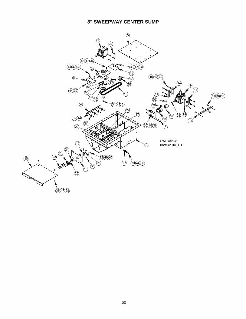
60
8" SWEEPWAY CENTER SUMP

61
8" SWEEPWAY CENTER SUMP PARTS LIST
REF. # DESCRIPTION QTY. 8” COMP. #
1 Clutch shifter arm assembly 1 E53132
2 Spacer washer, 3/8” ID, 2-1/4” OD 1 E5324
3 Weld support plate w/ snap ring, 10" 1 E5339
4 Side gate rail 2 E5350-14
5 Sump cover 1 E5354
6 Gearbox support cover 1 E5357
7 Top gearbox 1 E5374
8 Center sump shell 1 E5376
9 Lower gearbox 1 E5378
10 Mounting plate 1 E5387
11 Gearbox support angle brace 1 E53874
12 Chain cover 1 E53875
13 #50 chain, 75 links 1 E53876
14 Lower gearbox spacer bar 4 E53877
15 Slide gate 1 E5477
16 Sprocket, 50B18, 1” bore 1 E5837*
17 Key, 1/4 sq. x 1" 2 E5915
18 Three-tooth engaging clutch 1 E60011
19 3-bolt clutch base 1 E6002-01
20 Clutch base w/ set & pilot bearing, 2 bolt 1 E60031
21 Clutch spacer, 5/8” long 1 E60041
22 Clutch spacer, 7/16” long 1 E60042
23 Square-end shaft 1 E6006
24 Key, 1/4 x 1-1/2” 1 E9007
25 Key, 1/4" x 3/4” 1 G7508
26 1” flange bearing 1 J0003
27 Roller bearing 1-1/2”, 3/8” bore 10 J0045
28 Bolt, 5/16 - 18 x 3/4” 3 J0520
29 Carriage bolt, 5/16 - 18 x 2-1/2” 3 J0589
30 Bolt, 3/8 - 16 x 1-1/4” 4 J0616
31 Bolt, 3/8 - 16 x 1-1/4”, zinc plated 1 J06161
32 Screw, 7/16 - 14 x 1-1/2” 10 J0710
33 Stud bolt, 7/16 - 14 x 2-3/4” 4 J07211
34 Screw, 1/2 - 13 x 1-1/4” 3 J0728
35 Bolt, 1-1/2 x 1/2” 3 J0730
36 Hex nut, 5/16” - 18 6 J1002
37 Flat nut, 5/16” - 18 1 J1009
38 Hex nut, 3/8” - 16 2 J1020
39 Lock nut, 3/8” - 16 11 J1025
40 Hex nut, 7/16” - 14 2 J1035
41 Hex nut, 1/2" - 13 3 J1040
42 Setscrew, 5/16” - 18 2 J1080
43 Flat washer, 5/16” 2 J1111
44 Flat washer, 3/8” 11 J1117
45 Flat washer, 7/16" 8 J1120
46 Washer, 2-1/2” OD, 3/8” ID, 14ga 1 J1140
47 Split lock washer, 5/16” 6 J1200
48 Split lock washer, 3/8” 3 J1205
49 Split lock washer, 7/16” 10 J1210
50 Lock washer, 1/2" 3 J1215
51 Machine bushing, 1”, 18ga 2 J1266
52 Allen-head setscrew, 1/2 x 1-1/4” 2 J1390
53 Sprocket, 50B15H, 1” bore w/ keyway 1 J1665
54 #50 chain connector link 1 J1760 *Order E58371 to receive setscrews with sprocket

62
10" SWEEPWAY CENTER SUMP

63
10" SWEEPWAY CENTER SUMP PARTS LIST
REF. # DESCRIPTION QTY. 8” COMP. #
1 Clutch shifter arm assembly 1 E53132
2 Spacer washer, 3/8” ID, 2-1/4” OD 1 E5324
3 Weld support plate w/ snap ring, 10" 1 E5339
4 Side gate rail 2 E5350-14
5 Sump cover 1 E5354
6 Gearbox support cover 1 E5357
7 Chain cover 1 E5358
8 #60 chain, 73 links 1 E5359-01
9 Lower gearbox 1 E5360
10 Sprocket, 60B20, 1.1811” bore 1 E5373*
11 Top gearbox 1 E5375
12 Center sump shell 1 E5377
13 Gearbox support angle brace 1 E53874
14 Slide gate 1 E5478
15 Key, 1/4 sq. x 1" 2 E5915
16 Three-tooth engaging clutch 1 E60011
17 3-bolt clutch base 1 E6002-01
18 Clutch base w/ set & pilot bearing, 2 bolt 1 E60031
19 Clutch spacer, 5/8” long 1 E60041
20 Clutch spacer, 7/16” long 1 E60042
21 Mounting plate 1 E60051
22 Square-end shaft 1 E6018
23 Key, 1/4 x 1-1/2” 1 E9007
24 Key, 1/4" x 3/4” 1 G7508
25 1” flange bearing 1 J0003
26 Roller bearing 1-1/2”, 3/8” bore 10 J0045
27 Bolt, 5/16 - 18 x 3/4” 3 J0520
28 Carriage bolt, 5/16 - 18 x 2-1/2” 3 J0589
29 Bolt, 3/8 - 16 x 1-1/4” 4 J0616
30 Bolt, 3/8 - 16 x 1-1/4”, zinc plated 1 J06161
31 Screw, 7/16 - 14 x 1-1/2” 2 J0710
32 Stud bolt, 7/16 - 14 x 2-3/4” 4 J07211
33 Screw, 1/2 - 20 x 1-1/4” 8 J0724
34 Screw, 1/2 - 13 x 1-1/4” 1 J0728
35 Bolt, 1-1/2 x 1/2” 3 J0730
36 Hex nut, 5/16” - 18 6 J1002
37 Flat nut, 5/16” - 18 1 J1009
38 Hex nut, 3/8” - 16 2 J1020
39 Lock nut, 3/8” - 16 11 J1025
40 Hex nut, 7/16” - 14 2 J1035
41 Hex nut, 1/2" - 13 1 J1040
42 Setscrew, 5/16” - 18 4 J1080
43 Flat washer, 5/16” 2 J1111
44 Flat washer, 3/8” 11 J1117
45 Flat washer, 1/2” 8 J1125
46 Washer, 2-1/2” OD, 3/8” ID, 14ga 1 J1140
47 Split lock washer, 5/16” 6 J1200
48 Split lock washer, 3/8” 3 J1205
49 Split lock washer, 7/16” 2 J1210
50 Lock washer, 1/2" 9 J1215
51 Machine bushing, 30mm ID x 4mm OD 1 J1268
52 Allen-head setscrew, 1/2 x 1-1/4” 2 J1390
53 Sprocket, 60B20, 1-1/4” bore 1 J1695
54 #60 chain connector link 1 J1775
*Order E53731 to receive setscrews with sprocket

64
8” SWEEPWAY INDEPENDENT INTERMEDIATE SUMP, PARTS LIST
REF. # DESCRIPTION QTY. COMP. #
1 Gate catch 2 E7993
2 Roller bearing, 1-1/2”, 3/8” bore 8 J0045
3 Bolt, 5/16 - 18 x 3/4” 4 J0520
4 Screw, 3/8 - 16 x 1” 4 J0606
5 Screw, 3/8 – 16 x 1-1/2” 16 J0627
6 Hex nut, 1/4" – 20 8 J0990
7 Lock nut, 5/16” – 18 4 J1010
8 Lock nut, 3/8” – 16 4 J1017
9 Hex nut, 3/8” – 16 2 J1020
10 Lock nut, 3/8" – 16 8 J1025
11 Flat washer, 3/8” 24 J1117
12 Lock washer, 1/4”, 8 J1195
13 Split lock washer, 3/8" 8 J1205
14 Shaft collar, 7/8" 3 J1330
15 Carriage bolt, 1/4 - 20 x 3/4" 8 J05051
16 Plug, 3/8” 4 J5069
17 Sump lip 1 Y5082-02
18 Scraper 1 Y5086
19 Sump top weldment 1 Y5088
20 Slide gate 1 Y5131
21 Gate side 2 Y5285
22 Roller bracket 1 Y5286
23 Sump strap 1 Y5287

65
10" SWEEPWAY INDEPENDENT INTERMEDIATE SUMP, PARTS LIST
REF. # DESCRIPTION QTY. COMP. #
1 Gate catch 2 E7997
2 Roller bearing, 1-1/2”, 3/8” bore 8 J0045
3 Bolt, 5/16 - 18 x 3/4” 4 J0520
4 Screw, 3/8 - 16 x 1” 6 J0606
5 Screw, 3/8 – 16 x 1-1/2” 14 J0627
6 Hex nut, 1/4" – 20 8 J0990
7 Lock nut, 5/16” – 18 4 J1010
8 Lock nut, 3/8” – 16 6 J1017
9 Hex nut, 3/8” – 16 2 J1020
10 Lock nut, 3/8" – 16 8 J1025
11 Flat washer, 3/8” 24 J1117
12 Lock washer, 1/4”, 8 J1195
13 Split lock washer, 3/8" 8 J1205
14 Shaft collar, 7/8" 3 J1330
15 Carriage bolt, 1/4 - 20 x 3/4" 8 J05051
16 Flat-head screw, 3/8 – 16 x 1” 2 J06066
17 Sump lip 1 Y5082-02
18 Gate side 2 Y5085
19 Scraper 1 Y5086
20 Sump strap 1 Y5087
21 Sump top weldment 1 Y5088
22 Roller bracket, left 1 Y5108
23 Roller bracket, right 1 Y5109
24 Slide gate 1 Y5231

66
6”, 8” & 10" SWEEPWAY INTERMEDIATE SUMPS, PARTS LIST
* QTY. varies with sump size
REF. # DESCRIPTION QTY. COMP. #
1 Bearing, 1/4" ID, 5/8” OD * J0016
2 Screw, 1/4 – 20 x 1” * J05081
3 Hex nut, 1/4" – 20 * J0990
4 Lock washer, 1/4" * J1195

67
6" & 8" SWEEPWAY TOP GEARBOX, PARTS LIST
REF. # DESCRIPTION QTY. COMP. #
Complete gearbox, sump, top 6”, 8” (prior to 2011) E5325 Complete gearbox, sump, top 8”, 2011 E5374
1 Gearbox case, two hole 1 F9004
2 Snap ring, 1.37, 5160-137 1 J3589
3 Plug, sunk head, 1/2" hex center 2 J2615
4 Cup, 2-23/32” OD, 14276 1 J0115
5 Tapered bearing, 14137A, Timken, 1-3/8” 1 J0120
6 Bearing cup, Timken, 02820 1 J0125
7 Tapered bearing, 1-1/4”, .94, 02875 1 J0130
8 Seal, 1-3/8 x 2.129, R/C, 13650 1 J7010
9 Soft plug, 1-7/8”, PC 1 J6980
10 Machine bushing, 1-3/8”, 10ga, N rim 1 J1275
11 Open end plate w/ grease zerk cup & Sl 1 E59021
12 Gear, 21-tooth w/ 1-1/4" bore 1 F4742
13 Drive-in grease zerk, 1/4" 1 J3605
14 Shaft, 8-3/8 x 1-3/8" w/ keyway, 6", 8" (prior to 2011) 1 E5901
Shaft, 8.601, 1-3/8" w/ keyway, 8", 2011 1 E5908
15 Square key, 1/4" x 13/16" 1 J3619
16 Gear box hub 1 F9007
17 Bearing cup, L-44610 2 J0105
18 Tapered bearing, 14137A, Timken, 1-3/8” 2 J0111
19 Snap ring, 1.00, 329, Eaton 1 J3584
20 Upper gearbox connector shaft, 1 x 8” 1 E5903
21 Machine bushing, 1”, 1ga, N rim 1 J1265
22 Seal, 1.000 x 2.004, R/C, 10124 1 J6993
23 Square key, 1/4 x 9/16" 1 J3618
24 Small gear, (14 teeth) 1 F4740
25 Thin nylon lock nut, 3/4" - 16, PLT 1 J1055
26 Split lock washer, 5/16”, PLT 8 J1200
27 Screw, 5/16 - 18 X 1”, PLT, GR5 8 J0527
28 Shim, 3.88 x 5.12 x 0.003 As needed J7090
Shim, 3.88 x 5.12 x 0.010 As needed J70901

68
6" & 8" SWEEPWAY LOWER GEARBOX, PARTS LIST
REF. # DESCRIPTION QTY. COMP. #
Complete gearbox, lower sump, 6”, 8” (prior to 2011) E5320
Complete gearbox, lower sump, 8”, 2011 E5378
1 Shaft, 1-3/8” main, lower sump, 6”, 8” (prior to 2011) 1 E5900
Shaft, 10-7/16", 13/8" w/ keyway, 8", 2011 1 E5927
2 Open end plate w/ grease zerk & cup 1 E59021
3 Lower hub, 6” & 8” complete 1 F9015
Hub only F9007
4 Seal, 1-3/8” 1 J7010
5 1” keyway shaft x 6-1/2”, lower 1 F4738
6 Machine bushing, 1-3/8”, 10ga 1 J1275
7 Bearing, 14137A 1 J0120
8 Bearing, 02875 1 J0130
9 Bearing, L44643 2 J0110
10 Bearing cup, L44610 2 J0105
11 Bearing cup, 02820 1 J0125
12 Bearing cup, 14276 1 J0115
13 Machine bushing, 1”, 14ga 1 J1265
14 Street elbow, 1/2 x 90۫°, upper sump 1 J2520
15 Lock nut, 3/4” - 16 thin nylon 1 J1055
16 Gear, 21 teeth 1-1/4” bore 1 F4742
17 Gear, 14 teeth 1 F4740
18 Snap ring, 1” 1 J3584
20 Gearbox case, complete w/ grease zerk 1 F90041
Gearbox case only F9004 21 Grease zerk 1 J3605
22 1” seal 1 J6993
23 Soft plug, 1-7/8” 1 J6980
24 Square key, 1/4 x 13/16" 2 J3619
25 Black plug, 1/2” 1 J2615
26 1/2” center sunk head vented plug 1 J2616
27 Plastic shims, .003 thick As needed J7090
Plastic shims, .010 thick As needed J70901
28 Snap ring, 1-3/8” 1 J3589
29 Screw, 5/16 - 18 x 1”, GR5 (Not shown) 6 J0527
30 Screw, 5/16 - 18 x 1-1/4”, GR5 (Not shown) 2 J0550
31 Lock washer, 5/16 (Not shown) 8 J1200
32 Square key, 1/4 x 9/16" 1 J3618

69
10" SWEEPWAY TOP GEARBOX, PARTS LIST
REF. # DESCRIPTION QTY. COMP. #
1 Gearbox casting 1 F9004
2 Drive-in grease zerk, 1/4” 1 J3605
3 Upper gearbox connection shaft, 1 x 8” 1 E5903
4 Square key, 1/4 x 9/16" 1 J3618
5 Standard hub w/cup (J0105) 1 F9007
6 Bearing cup, L-44610 2 J0105
7 Tapered bearing, 14137A, Timken, 1-3/8” 2 J0111
8 Thin nylon lock nut, 3/4" -16, PLT 1 J1055
9 Machine bushing, 1” x 14ga, N-rim 1 J1265
10 Snap ring, 1.00, 329, Eaton 1 J3584
11 Seal, 1.000 x 2.004, R/C, 10124 1 J6993
12 Bevel gear, 1” bore, 18 teeth 1 S6051
13 Bearing cup, Timken, 02820 1 J0125
14 Split lock washer, 5/16”, PLT 8 J1200
15 Machine bushing, 1-3/8” x 10ga, N-rim 1 J1275
16 1/2" center sunk hex head plug 1 J2615
17 1/2" center sunk head vented plug 1 J2616
18 Snap ring, 1.37, 5160 - 137 1 J3589
19 Square key, 1/4” x 13/16” 1 J3619
20 Soft plug, 1-7/8”, PC 1 J6980
21 Shaft, 8-3/4”, w/ keyway 1 E5379
22 Screw, 5/16 – 18 x 1”, PLT, GR5 8 J0527
23 Open end plate 1 E5902
24 Cup, 2-23/32” OD 14276 1 J0115
25 Seal, 1.375 x 2.129, R/C, 13650 1 J7010
26 Bevel gear, 1-1/4” bore, 18 teeth 1 E5372
27 Tapered brng, 14137 A, Timken, 1-3/8” 1 J0120
28 Tapered bearing, 1-1/4”, .94, 02875 1 J0130
29 Shim, 3.88 x 5.12 x 0.003 As needed J7090
30 Shim, 3.88 x 5.12 x 0.010 As needed J70901

70
10" SWEEPWAY LOWER GEARBOX, PARTS LIST
REF. # DESCRIPTION QTY. COMP. #
1 Hub casting, HD, 1-3/8”, 10”, 1998 1 E5365
2 Gearbox shaft, 10” 1 E5366
3 Shaft, 8-5/16” 1 E5367
4 Key, 1/4” sq. x 1” 1 E5915
5 Bottom gearbox casting, HD, 3 hole 1 F9051
6 Bevel gear, 18 tooth, 1-1/4” bore 1 F9052
7 Gear, 27-tooth, 1-3/8” bore 1 F9053
8 Closed end plate 1 F9061-01
9 Gearbox hub, 1-3/8" 1 F9065-01
10 Key, 3/8 x 1-1/4” 1 G5315
11 Bearing, 1-3/8” ID, 3872, Timken 1 J0027
12 Cup, 3-3/8” OD, 3820, 3821, Timken 1 J0028
13 Cup, 2-23/32” OD, 14276 3 J0115
14 Tapered bearing, 14137A, Timken, 1-3/8” 3 J0120
15 Screw, 3/8 - 24 x 1”, PLT, GR5 18 J0612
16 Thin nylon lock nut, 1-1/8” – 12, PLT 1 J1067
17 Split lock washer, 3/8" 18 J1205
18 Machine bushing, 1-3/8 x 10ga, N-rim 1 J1275 19 Street elbow, 1/2”, 90°, Sch 40 1 J2520
20 1/2" center sunk hex head plug 2 J2615
21 1/2” center sunk head vented plug 1 J2616
22 Snap ring, 1.37, 5160-137 1 J3589
23 Drive-in grease zerk, 1/4" 1 J3605
24 Seal, 1.38 ID, N, 472658 2 J7061
25 Shim, 4.625 x 6.010 x 0.003 1 J7085
26 Shim, 4.625 x 6.010 x .010 4 J7088

71
TOP GEARBOX BEARING SUPPORT SLIDE PLATE ASSY., PARTS LIST
E5317 (6”)* E5339 (8” & 10”)
REF. # DESCRIPTION QTY. 6” COMP. # 8” & 10” COMP. #
1 Bearing, 1-1/4” ID, 2-1/2” OD 2 J0060 NA
Bearing, 1.1811 ID, 2.8346 OD 1 NA J00599
2 Snap ring, 2.047” 1 NA J35991
*Also 8” prior to 2011

72
CLUTCH SHIFTER ARM ASSEMBLY, PARTS LIST
E5313 (6”) E53132 (8” & 10”)
REF. # DESCRIPTION QTY. 6” COMP. # 8” & 10” COMP. #
1 Clutch arm weldment 1 E53131 NA
NA E5351
2 Clutch shifter support bracket 1 E5311 NA
NA E5352
3 Bearing, 3/4",cam follower 2 J0035 J0035
4 Screw, 3/8 -16 x 1” 2 J0606 J0606
5 Lock nut, 3/8” – 16 2 J1025 J1025
6 Hex nut, 3/8” – 24 2 J1030 J1030
7 Split lock washer, 3/8” 4 J1205 J1205

73
8" SWEEPWAY RACK & PINION OPENER ASSEMBLY, PARTS LIST
REF. # DESCRIPTION QTY. COMP. #
1 Opener slide guide 2 E5962
2 Opener crank shaft 1 E5964
3 8” slide plate rack weldment 1 E5916
4 Spacer opener 2 E5966
5 Opener pinion gear 1 E5961
6 Key stock, 1/4 x 1-1/2" 1 E9007
7 Cap screw socket, 5/16 x 1-3/4”, FH 8 J0579
8 Split lock washer, 5/16”, PLT 8 J1200
9 Hex nut, 5/16” - 18, PLT 8 J1002
10 Shaft collar, 1" 1 J1335
11 Machine bushing, 1”, 18ga 5 J1266
12 Lock washer, 1/2", PLT 2 J1215
13 Hex nut, 1/2" - 13, PLT 2 J1040
14 Screw, 1/2 - 13 x 6”, PLT, GR5 2 J0762
15 8” top frame 1 E5918
16 8” bottom frame 1 E5917
17 8” opener support strap (For assembly drawing) 1 E5913

74
10" SWEEPWAY RACK & PINION OPENER ASSEMBLY, PARTS LIST
REF. # DESCRIPTION QTY. COMP. #
1 Bottom frame 2 E5962
2 Opener crank shaft 1 E5964
3 Slide plate rack weldment 1 E5963
4 Opener spacer 2 E5966
5 Opener pinion gear 1 E5961
6 Key 1 E9007
7 Cap screw socket, 5/16" x 1-3/4", FH 4 J0579
8 Split lock washer, 5/16”, PLT 4 J1200
9 Hex nut, 5/16” - 18, PLT 4 J1002
10 1” shaft collar 1 J1335
11 Machine bushing, 1”, 18ga 5 J1266
12 Lock washer, 1/2", PLT 2 J1215
13 Hex nut, 1/2" - 13, PLT 2 J1040
14 Screw, 1/2 - 13 x 6”, PLT, GR5 2 J0762
15 10” opener support strap 1 E5968
16 Top frame 1 E5965-02
17 Bottom frame 1 E5965-01

75
4-TO-1 REDUCTION DRIVE WHEEL ASSEMBLY, PARTS LIST Standard on all 6” sweeps and on 8” & 10” sweeps in bins up to 33’ dia.
REF. # DESCRIPTION QTY. 6" COMP # 8" COMP. # 10" COMP. #
Complete wheel E6094 E6092 E6093
6” assembly mount, 2010 1 E6095 - -
1 8” assembly mount, split, w/ brng., 2010 1 - E6096 -
10” assembly mount, split, w/ brng., 2010 1 - - E6097
2 Back plate w/ roller, 2010 1 E6087 E6087 E6087
3 10" rubber ring, 2000 3 E60121-01 E60121-01 E60121-01
4 Back plate, 9.25" Dia., 2010 1 E6088 E6088 E6088
5 Drive shaft w/ 8-tooth sprocket 1 E6049 E6049 E6049
6 Self-drilling screw, 1/4 - 14 x 2-1/4, PLT 6 J05041 J05041 J05041
7 Flat washer, 3/4", PLT 1 J1130 J1130 J1130
8 Lock nut, 3/4" - 10, GR5 1 J1057 J1057 J1057
9 Screw, 3/8 - 16 x 1”, PLT, GR5 4 J0606 J0606 J0606
10 Split lock washer, 3/8", PLT 4 J1205 J1205 J1205
11 Hex nut, 3/8" - 16, PLT 4 J1020 J1020 J1020
12 Machine bushing, 3/4 x 1-1/4”, 14ga, N-rim 2 J1260 J1260 J1260
13 Screw, 3/4 -10 x 4-1/2”, PLT, GR5 1 J0817 J0817 J0817
14 Screw, 5/16 - 18 x 1-3/4”, PLT, GR5 2 J0570 J0570 J0570
15 Lock nut, 5/16” - 18, PLT 2 J1010 J1010 J1010
16 1” flange bearing w/ locking collar 1 J0003 J0003 J0003

76
16-TO-1 REDUCTION DRIVE WHEEL ASSEMBLY, PARTS LIST 6”, 8” & 10” (Standard in bins 36’ dia. and larger)
REF. # DESCRIPTION QTY. 6” COMP. # 8” COMP. # 10” COMP. #
Complete gearbox w/ bracket 1 E7336 E7337 E7339
Complete gearbox w/o bracket 1 E7330 E7330 E7330
1 Gearbox bracket 1 E7306 E7308 E7310
2* Gearbox inside side cover 1 E7317 E7317 E7317
3* Gearbox outside cover 1 E7318 E7318 E7318
4 Wheel, 17” OD 1 E7332 E7332 E7332
5 Gearbox input shaft weldment w/ sprocket 1 E7320 E7320 E7320
6 Gearbox output shaft weldment w/ sprocket 1 E7319 E7319 E7319
7 Chain, # 40, 37 links 3 E7327 E7327 E7327
8 Sprocket tree,4A30-40A12, 1” bore 2 J7312 J7312 J7312
9 Bearing, 1-1/4” ID, 2-1/2” OD 1 J0060 J0060 J0060
10 Bearing, 3/4" ID, 1-5/8” OD 2 J00703 J00703 J00703
11 Bushing, 3/4" ID, 1-3/4” OD 4 J00745 J00745 J00745
12 Thrust washer, 3/4" ID, 1-2/4” OD 2 J00746 J00746 J00746
13 Bushing, 1-15/16” ID, 2-1/8” OD 1 J00817 J00817 J00817
14 Flat washer, 11/16” 1 E7322 E7322 E7322
15 Screw, 5/16 - 18 x 1-3/4” 2 J0570 J0570 J0570
16 Lock nut, 5/16” – 18 2 J1010 J1010 J1010
17 Screw, 5/16 – 18 x 3” 12 J05952 J05952 J05952
18 Screw, 3/8 - 16 x 1” 2 J0606 J0606 J0606
19 Hex nut, 3/8" – 16 2 J1020 J1020 J1020
20 Split lock washer, 3/8" 2 J1205 J1205 J1205
21 Split lock washer, 5/16" 12 J1200 J1200 J1200
22 Split lock washer, 5/8” 1 J1218 J1218 J1218
23 Screw, 5/8 - 11 x 1-1/2” 1 J0781 J0781 J0781
24 Flat washer, 3/8” 2 J1117 J1117 J1117
25 Drive wheel urethane tread 8 E7329 E7329 E7329
26 Drive wheel rim 1 E7328 E7328 E7328
*Must be replaced together if replacement necessary

77
INNER BELT SHIELD INSTALLATION GUIDE Use drawing and table below to determine which knockout panel(s) must be removed from inner section of belt shield to accommodate motor shaft, depending on discharge powerhead and motor size.
POWERHEAD MOTOR SIZE (HP)
1 2
(F145T) 2
(E182T) 3 5 7.5 10 15 20
HORZ. 6" 1 1 2 2 2 2 2 N/A N/A
HORZ. 8" 1 1 2 2 2 2 2 2 2
HORZ. 10" 1 1 2 2 2 2 2 2 2
INCLINE 6" 1 1 2 2 2 2 2 N/A N/A
INCLINE 8" 1 1 2 2 2 2 2 N/A N/A
INCLINE 10" 1 1 2 2 2 2 2 3 3
INCLINE, 12" None None 3 3 3 3 3 3 3
VERT. 6" (2 MTR) 1 1 2 2 2 2 2 2 2
VERT. 8" (2 MTR) 1 1 2 2 2 2 2 2 2
VERT. 10" (2 MTR) 1 1 2 2 2 2 2 3 3
TRANSFER 6" 1 1 2 2 2 2 2 N/A N/A
TRANSFER 8" 1 1 2 2 2 2 2 N/A N/A
TRANSFER 10" 1 1 2 2 2 2 2 N/A N/A
TOP DRIVE 6" 1 1 2 2 2 2 2 N/A N/A
TOP DRIVE 8" 1 1 2 2 2 2 2 N/A N/A

78
TROUBLESHOOTING GUIDE
PROBLEM REASON SOLUTION
1. Sweep is not moving around bin. Scraper too close to floor. Raise scrapers up.
Bent edge is down by floor. Turn scraper around so sharp edge is at bottom.
Obstacles may be hindering forward movement.
Check for any obstacles that scraper could be catching on. May need to raise scraper.
Grain is keeping sweep from moving into pile.
Remove front carrier wheels (on sweeps larger than 39') to allow easier forward movement.
2. Sweep is not filling unload auger to capacity. (10” Sweepway)
Sweep is not going fast enough. Increase sweep auger capacity by increasing size of lower gearbox 20-tooth sprocket to a 24-tooth sprocket, (Part #J16957). May have to lengthen chain with 24-tooth sprocket. It will increase speed by 20%.
3. Drive chain breaking. (8" Sweepway)
Grain piling in center of bin. Make sure center sump gate is fully open.
Sweep can be slowed down by decreasing size of sprocket on lower gearbox from a 15-tooth to a 12-tooth sprocket, (Part # J1660). May have to shorten chain using a 12-tooth sprocket. It will decrease speed by 20%.
4. When using an incline auger, capacity is cut dramatically.
Moving very small grains or hard flowing grains. Example: rice, wheat, soybeans, etc.
Weld a piece of flighting, (6-8" incline use Part #E5638, 8-10" incline use Part #E5639) onto end of unload auger to get flighting extended fully to U-joint. This will decrease amount of gap grain has to flow through, increasing capacity.
5. Connector link coming off. Chain is too high & rubbing on top of sump.
On units built prior to 2003, chain can be lowered by replacing old sprocket on top gearbox with a new sprocket (E5837). Old spacer (E60041) on lower gearbox must also be replaced with a new spacer (E60042).
Connector link is on backwards. Connector link clip needs to have closed end leading chain around.
LUBRICATION Use 140-weight gear oil in gearboxes. Gearboxes should be checked every time bin is empty. Check plugs are on back of gearboxes. Gearboxes should be about half full. Add grease to top bearing through zerk on top of each sump gearbox. On single-motor vertical drive, add oil through fill plug. Grease roller chain in sump every time bin is empty. Factory oil used in gearboxes is Mobil Gear 636, 140-weight.

79
QUICK REFERENCE PARTS LISTS
MOTORS
OPTIONAL - FARM-DUTY MOTORS (1750)
HP PH FRAME SHAFT LBS. COMP. #
2 1 E182T 1-1/8" 67 H2175
3 F145T 7/8" 50 H2475
3 1 J184T 1-1/8" 113 H2845
3 E182T 1-1/8" 60 H3345
5 1 L184T 1-1/8" 122 H3675
3 F184T 1-1/8" 72 H4190
7.5 1 K215T 1-3/8" 130 H4900
3 213T 1-3/8" 84 H4910
10 1 215T 1-3/8" 143 H5300
3 215T 1-3/8" 94 H5310
15 3 254T 1-5/8" 141 H6110
20 3 256T 1-5/8" 188 H6610
All motors are TEFC (Totally enclosed, fan cooled).
MOTOR PULLEYS
DIA. BORE GROOVE SINGLE DOUBLE TRIPLE
3-1/2" OD
5/8" B J0309 --- ---
7/8" B J0310 J0315 ---
1-1/8" B J0312 J0317 ---
1-3/8" B J0313 J0318 J0331
3-3/4” OD 1-5/8"* B --- J03211* J0332*
*Requires split-taper bushing to obtain bore size. Order "SH" for 3-3/4".
SPLIT TAPER BUSHINGS
BUSHING 1-1/8" BORE 1-3/8" BORE 1-5/8" BORE 1-7/8" BORE
SD J04191 J04264 J04263 J04284
SDS J04194 J04241 --- ---
SH --- --- J04242 ---

80
REPLACEMENT VERTICAL FLIGHTING, SHAFTS & TUBES -- STANDARD BOTTOM DRIVE
NOTE: Vertical flight numbers include flipper and top and bottom shafts.
FLIGHTING FOR VERTICAL AUGER
DESCRIPTION 6" COMP. # 8" COMP. # 10" COMP. #
14' w/ dbl flight, 1" E5806 - - - - - - - - - -
14' w/ dbl flight, 1-1/4" - - - - - E58071 E5783
16' w/ dbl flight, 1" E5846 - - - - - - - - - -
16' w/ dbl flight, 1-1/4" - - - - - E5847 E57833
18' w/ dbl flight, 1" E5848 - - - - - - - - - -
18' w/ dbl flight, 1-1/4" - - - - - E5849 E57832
20' w/ dbl flight, 1-1/4" - - - - - E58541 E57834
VERTICAL TOP SHAFT
DESCRIPTION 6" COMP. # 8" COMP. # 10" COMP. #
1 x 12-1/8" w/ hole E58091 - - - - - - - - - -
1 x 10" w/ hole (Pre-1990) E5809 E5809 - - - - -
1 5/8 x 13-5/8" w/ hole (Pre-1990) - - - - - - - - - - E58241
1-1/4 x 12-3/8" w/ hole - - - - - E97711 - - - - -
1 x 1-1/4 x 12-3/8" repl. w/ hole - - - - - E9753 - - - - -
2" x 15-5/8" w/ hole (1998) - - - - - - - - - - E58243
Flipper E5416 E5689 E5689
BOTTOM SHAFT
DESCRIPTION 6" COMP. # 8" COMP. # 10" COMP. #
1 x 10⁻⁷/8" w/ keyway E58081 - - - - - - - - - -
1 x 14-1/4" w/ keyway (Prior 1990) E5808 E5808
1-1/4 x 12-1/8" w/ keyway - - - - - E9751 - - - - -
1 x 1-1/4 x 10-1/8" repl. w/ keyway - - - - - E9752 - - - - -
2 x 1-1/4 x 13-7/8" w/ keyway (1998) - - - - - - - - - - E58252
GALVANIZED TUBE
DESCRIPTION 6" COMP. # 8" COMP. # 10" COMP. #
10' long for 14' vertical auger E5804 E5805 E57842
8' long for 14' vertical auger - - - - - - - - - - E5784
12' long for 16' vertical auger E5842 E5843 E57841
14' long for 18' vertical auger E5844 E5845 E57843
16' long for 20' vertical auger F4801 F4915 - - - - -

81
UNLOAD AUGER FLIGHTING ASSEMBLY
6” SWEEPWAY
BIN DIAMETER COMP. #
*15'-15' 6" E6430
16' 5" (5M) E64301
*18'-18' 7" E6431
19' 8" (6M) E64310
*21'-21' 8" E6432
22' 11" (7M) E64320
*24'-24' 9" E6433
26' 3" (8M) E64331
*27'-27' 10" E6434
29' 6" (9M) E64341
*30'-31' E6435
*33'-34' E6436
36' (11M) E6417
37' 1" E6437
* In larger bin dia. listed, use E5328 adapter to extend sweep.
8" SWEEPWAY
BIN DIA. COMP. # COMP. #
*15'-15' 6" - E6450
16' 5" (5M) - E6449
*18'-18' 7" - E6451
19' 8" (6M) - E64510
*21'-21' 8" - E6452
22' 11" (7M) - E64521
*24'-24' 9" - E6453
26' 3" (8M) - E64531
*27'-27' 10" - E6454
29' 6" (9M) - E64541
*30'-31' - E6455
*33'-34' - E6456
36' (11M) - E6457
37' 1" - E6457
42' E6472 E64582
42' 8" (13M) E6472 E64584
43' 3" E6472 E64591
48' E6472 E64602
49' 3" (15M) E6472 E64611
54' E6472 E64621
55' 8" E6472 E64631
60' E6472 E64641
61' 10" E6472 E64651
* In larger bin dia. listed, use E5328 adapter to extend sweep.
10" SWEEPWAY
BIN DIA. COMP. # COMP. #
*21'-21' 8" - E6482
22' 11" (7M) - E64821
*24'-24' 9" - E6483
26' 3" (8M) - E64831
*27'-27' 10" - E6484
29' 6" (9M) - E64841
*30'-31' - E6485
*33'-34' E6497 E64861
36' (11M) E6497 E64871
37' 1" E6497 E64871
42' E6497 E64883
42' 8" (13M) E6497 E64884
43' 3" E6497 E64891
48' E6497 E64901
49' 3" (15M) E6497 E64911
54' E6497 E64922
55' 8" E6497 E64932
60' E6497 E64941
61' 10" E6497 E64951
* In larger bin dia. listed, use E5328 adapter to extend sweep.

82
SWEEP AUGER REPLACEMENT KITS
6” SWEEPWAY
BIN DIAMETER COMP. #
15'-15' 6" E82200
16' 5" (5M) E82201
18'-18' 7" E82202
19' 8" (6M) E82203
21'-21' 8" E82204
22' 11" (7M) E82205
24'-24' 9" E82206
26' 3" (8M) E82207
27'-27' 10" E82208
29' 6" (9M) E82209
30'-31' E82210
33'-34' E82211
36' (11M) E82212
37' 1" E82213
8” SWEEPWAY 10” SWEEPWAY
BIN DIAMETER COMP. #
24'-24' 9" E82237
26' 3" (8M) E82238
27'-27' 10" E82239
29' 6" (9M) E82240
30'-31' E82241
33'-34' E82242
36' (11M) E82243
37' 1" E82244
42' E82245
42'8" E82246
43'3" E82247
48' E82248
49'3" E82249
54' E82250
55'8" E82251
60' E82252
61'10" E82253
BIN DIAMETER COMP. #
15'-15' 6" E82214
16' 5" (5M) E82215
18'-18' 7" E82216
19' 8" (6M) E82217
21'-21' 8" E82218
22' 11" (7M) E82219
24'-24' 9" E82220
26' 3" (8M) E82221
27'-27' 10" E82222
29' 6" (9M) E82223
30'-31' E82224
33'-34' E82225
36' (11M) E82226
37' 1" E82227
42' E82228
42'8" (13M) E82229
43'3" E82230
48' E82231
49'3" (15M) E82232
54' E82233
55'8" (17M) E82234
60' E82235
61'10" E82236

83
NOTES
___________________________________________________________________________________________
___________________________________________________________________________________________
___________________________________________________________________________________________
___________________________________________________________________________________________
___________________________________________________________________________________________
___________________________________________________________________________________________
___________________________________________________________________________________________
___________________________________________________________________________________________
___________________________________________________________________________________________
___________________________________________________________________________________________
___________________________________________________________________________________________
___________________________________________________________________________________________
___________________________________________________________________________________________
___________________________________________________________________________________________
___________________________________________________________________________________________
___________________________________________________________________________________________
___________________________________________________________________________________________
___________________________________________________________________________________________
___________________________________________________________________________________________
___________________________________________________________________________________________
___________________________________________________________________________________________
___________________________________________________________________________________________
___________________________________________________________________________________________
___________________________________________________________________________________________
___________________________________________________________________________________________
___________________________________________________________________________________________
___________________________________________________________________________________________
___________________________________________________________________________________________
84
CONTACT INFORMATION
Owner’s manuals are available from Sukup and additional copies can be requested at the address, phone number or e-mail address shown below. Please indicate manual number L1435 when requesting Sweepway Owner’s Installation & Operation Manual.
Sukup Dealer Information
Dealer name: ___________________________
Address: ______________________________
Cell phone: ____________________________
Office phone:___________________________
Fax:___________________________________
In Case of Emergency
Have emergency numbers and written directions to your location near a phone, and arrange and practice a safety plan.
Sukup Manufacturing Co. 1555 255th Street, Box 677
Sheffield, Iowa, USA 50475-0677 Phone: 641-892-4222 Fax: 641-892-4629
Website: www.sukup.com Email: [email protected]
Ambulance • Fire • Police: 9-1-1
Bin rescue team:_________________________
Local EMS team:_________________________
911 address of work site:__________________
Directions to work site: ___________________