SWE 760 Real-Time Software Design Lecture 6 –Dynamic ...
19
A-1 Copyright 2016 H. Gomaa SWE 760 Real-Time Software Design Lecture 6 – Dynamic Interaction Modeling for Real-Time Embedded Systems Reference: H. Gomaa, Chapters 9 - Real-Time Software Design for Embedded Systems, Cambridge University Press, 2016 Hassan Gomaa Dept of Computer Science George Mason University Fairfax, VA Copyright © 2016 Hassan Gomaa All rights reserved. No part of this document may be reproduced in any form or by any means, without the prior written permission of the author. T Copyright © 2016 Hassan Gomaa 2 Figure 4.1 COMET/RTE life cycle model Requirements Modeling Analysis Modeling Incremental Software Construction Incremental Software Integration System Testing Incremental Prototyping Customer User Design Modeling System Structural Modeling
Transcript of SWE 760 Real-Time Software Design Lecture 6 –Dynamic ...

A-1
Copyright 2016 H. Gomaa
SWE 760 Real-Time Software Design
Lecture 6 – Dynamic Interaction Modeling for Real-Time Embedded Systems
Reference: H. Gomaa, Chapters 9 - Real-Time Software Design for Embedded Systems, Cambridge University Press, 2016
Hassan Gomaa
Dept of Computer ScienceGeorge Mason University
Fairfax, VA
Copyright © 2016 Hassan Gomaa
All rights reserved. No part of this document may be reproduced in any form or by any means, without the prior written permission of the author.
T
Copyright © 2016 Hassan Gomaa 2
Figure 4.1 COMET/RTE life cycle model
Requirements Modeling
Analysis Modeling
Incremental Software
Construction
Incremental Software
Integration
System Testing
Incremental Prototyping
Customer
User
Design Modeling
System Structural Modeling

A-2
Copyright 2016 H. Gomaa
Analysis Modeling
• Static Modeling
– Define entity classes and relationships
• Dynamic State Machine Modeling
– Real-time systems are highly state dependent
– Actions depend on input event AND current state
• Object Structuring
– Determine objects that realize each use case
• Dynamic Interaction Modeling
– Determine sequence of interactions among objects
3
Copyright 2016 H. Gomaa4
Dynamic Interaction Modeling
• Use cases realized in Dynamic Model– Show objects participating in each use case
• Determine how objects participate in use case – Use object structuring criteria to determine objects
• Stereotype for each object structuring criterion– Shows sequence of object interactions in use case
• Depict on – communication diagram or – sequence diagram
• State dependent control objects– Modeled using statecharts
• Dynamic Modeling– Approach to determine how objects interact with each
other to support use case

A-3
Copyright 2016 H. Gomaadm-5
Dynamic Modeling
• Determine how objects interact with each other to support use case
– Start with external event from actor
– Determine objects needed to support use case
– Determine sequence of internal events following external event
– Depict on communication diagram or sequence diagram
• Stateless (non state-dependent) Dynamic Modeling
• State dependent Dynamic Modeling
Copyright 2016 H. Gomaadm-6
Stateless Dynamic Modeling
• Start with use case
• Determine boundary objects
– Receives external events from actor
• Determine internal objects
– Receive messages from boundary objects
• Determine object interactions
– Sequence of messages passed
• Develop main interaction sequence (scenario)
• Develop alternative sequences
– For alternative branches of use case
– E.g, for error handling or less frequently occurring conditions

A-4
Copyright 2016 H. Gomaa
Example of Stateless Dynamic Modeling
7
Timer
Send Vehicle Status
Driver
«timer actor»
(secondary actor)
Figure 9.4 Send Vehicle Status use case
(primary actor)
«human actor»
Copyright 2016 H. Gomaa
Example of Stateless Dynamic Modeling
8
«external timer»: DigitalTimer
«timer»: VehicleTimer
«output»: VehicleDisplay
Output
«entity»: VehicleData
Driver
1: Timer Event
2: read(out location, out speed)
3: Vehicle Status
4: Vehicle Status
Fig 9.5: Sequence diagram for Send Vehicle Status use case

A-5
Copyright 2016 H. Gomaa
Example of Stateless Dynamic Modeling
9
Copyright 2016 H. Gomaa10
State Dependent Dynamic Modeling
• Object interaction controlled by statechart(s)
– Control object
• Executes statechart
• Activates/deactivates other objects
• For each use case
– Determine objects participating in use case
– Determine sequence of object communication
– Develop statechart for control object
• For each event that arrives at control object
– Determine state transition from current state to next state
– Determine actions and activities to be executed
– Determine objects required to perform actions and activities
A-6
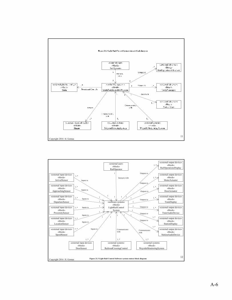
Copyright 2016 H. Gomaa11
Copyright 2016 H. Gomaa12
«software system»«block»
LightRailControl System
«external input device»«block»
ArrivalSensor
«external input device»«block»
ApproachingSensor
«external input device»«block»
DepartureSensor
«external input device»«block»
ProximitySensor
«external input device»«block»
LocationSensor
«external input device»«block»
SpeedSensor
«external output device»«block»
MotorActuator
«external output device»«block»
DoorActuator
«external output device»«block»
TrainDisplay
«external output device»«block»
TrainAudioDevice
«external output device»«block»
StationDisplay
«external output device»«block»
StationAudioDevice
«external system»«block»
RailroadCrossingControl
«external user»«block»
RailOperator
«external input device»«block»
DoorSensor
Interacts with
Outputs to
Outputs to
Outputs to
Outputs to
Outputs to
Outputs toInputs to
Inputs to
Inputs to
Inputs to
Inputs to
Inputs to
1..*
1..*
1..*
1..*
1..*
1..*
1..*
Inputs to
11
1
1
1
11 1
1
1
Communicateswith
11
1
1
1
1
1..*
1..*
1..*
1..*
1..*
1..*
«external system»«block»
WaysideMonitoringSystem
Communicateswith
1
1
Outputs to
1..*
«external output device»«block»
RailOperationsDisplay
1..*1..*
Figure 21.3 Light Rail Control Software system context block diagram

A-7
Copyright 2016 H. Gomaa13
ArrivalSensor
Control Train Operation
Control Train at StationArrive at Station Depart from Station
Departure Sensor
ApproachingSensor
DoorActuator
DoorSensor
Railroad Media
«include» «include» «include»
«use case package»LightRailOperations
Motor
Figure 21.4 Light Rail Control System actors and use cases: Light Rail Operations use case package
Copyright 2016 H. Gomaa14
Control Train at StationArrive at Station Depart from Station
«include» «include» «include»
«use case package»LightRailOperations
Suspend Train Dispatch Train
«use case package»TrainDispatchAnd
Suspend
«include»
DoorSensor
Rail Operator
Railroad Media
Door Actuator
Figure 21.5 Light Rail Control System: Train Dispatch and Suspend use case package

A-8
Copyright 2016 H. Gomaa15
Arrive at Station Depart from Station
«extend» «extend» «extend»
«use case package»LightRailOperations
Detect Hazard Presence Detect Hazard Removal
«use case package»RailroadHazardDetection
«extend»
ProximitySensor
Motor
Figure 21.6 Light Rail Control System: Railroad Hazard Detection
Copyright 2016 H. Gomaa16
Cruising
Stopping
Entry / Open Doors
Doors Opening
Approaching
Entry / Send Approached
Stopped / Send Arrived
Approached/ Decelerate
Arrived/ Stop
Figure 21.9 State machine for Arrive at Station use case

A-9
Copyright 2016 H. Gomaa17
Doors Closing
Entry / Open Doors
Doors Opening
Doors Open
Exit / Close Doors
Opened / Start Timer
After (Timeout) [All Clear] / Send Departing
Figure 21.10 State machine for Control Train at Station use case
Copyright 2016 H. Gomaa18
Doors Closing
Cruising
Accelerating
Entry / Accelerate
Closed
Reached Cruising / Cruise
Figure 21.11 State machine for Depart from Station use case
Departed / Send Departed

A-10
Copyright 2016 H. Gomaa19
Out of Service
Entry / Open Doors
Doors Opening
Doors Open
Exit / Close Doors
Opened / Start Timer
After(Timeout)[Suspending] / Send Out of Service
Figure 21.12 State machine for Suspend Train use case
Copyright 2016 H. Gomaa20

A-11
Copyright 2016 H. Gomaa21
Copyright 2016 H. Gomaa22

A-12
Copyright 2016 H. Gomaa23
Out of Service
Doors Closing
Cruising
Stopping
Emergency Halt
Hazard Detected
Hazard Removed [Not Approaching] / Send Hazard Removed
Hazard Detected
After(Timeout)[Hazard] / Start Timer
Entry / Open Doors
Doors Opening
Doors Open
Exit / Close Doors
Accelerating
Entry / Accelerate
Approaching
Entry / Send Approached
Emergency StoppingEntry / Emergency Stop, Send Hazard
DetectedHazard Detected
Hazard Removed [Approaching Station] / Accelerate Slowly, Send Hazard Removed
Hazard Removed [Approaching Station] / Accelerate Slowly, Send Hazard Removed
Dispatch / Send In Service
Opened / Start Timer
After (Timeout) [All Clear] / Send Departing
After(Timeout)[Suspending] / Send Out of Service
Closed
Stopped / Send Arrived
Reached Cruising / Cruise
Approached/ Decelerate
Approached/ Decelerate
Arrived/ Stop
Hazard Removed [Not Approaching] / Send Hazard Removed
Stopped / Send Stopped
Figure 21.16 Flat state machine for Control Train
Departed / Send Departed
Copyright 2016 H. Gomaa24
Out of Service
Doors Closing
Cruising
Stopping
Emergency Halt
Hazard Removed [Not Approaching]
Hazard Detected
After(Timeout)[Hazard] / Start Timer
Entry / Open Doors
Doors Opening
Doors Open
Exit / Close Doors
Accelerating
Entry / Accelerate
Approaching
Entry / Send Approached
Emergency StoppingEntry / Emergency Stop, Send Hazard
Detected
Hazard Removed [Approaching Station] / Accelerate Slowly
Dispatch / Send In Service
Opened / Start Timer
After (Timeout) [All Clear] / Send Departing
After(Timeout)[Suspending] / Send Out of Service
Closed
Stopped / Send Arrived
Reached Cruising / Cruise
Approached/ Decelerate
Approached/ Decelerate
Arrived/ Stop
Stopped / Send Stopped
In Motion
Exit: Send Hazard Removed
Emergency
Figure 21.17 Hierarchical state machine for Control Train
Departed / Send Departed

A-13
Copyright 2016 H. Gomaa25
«software system»«block»LightRailControlSystem«external input device»
«block»ArrivalSensor
«external input device»«block»
ApproachingSensor
«external input device»«block»
DepartureSensor
«external input device»«block»
ProximitySensor
«external input device»«block»
LocationSensor
«external input device»«block»
SpeedSensor
«external output device»«block»
MotorActuator
«external output device»«block»
DoorActuator
«external output device»«block»
TrainDisplay
«external output device»«block»
TrainAudioDevice
«external output device»«block»
StationDisplay
«external output device»«block»
StationAudioDevice
«external user»«block»
RailOperator
«external input device»«block»
DoorSensor
Interacts with
Outputs to
Outputs to
Outputs to
Outputs to
Outputs to
Outputs to
Inputs to
Inputs to
Inputs to
Inputs to
Inputs to
Inputs to
1..*
1..*
1..*
1..*
1..*
1..*
1..*
Inputs to
1
Communicateswith
1..*
1..*
1..*
1..*
1..*
1..*
Communicateswith
«user interaction»«subsystem»
RailOperationsInteraction
«service»«subsystem»
RailOperationsService
«control»«subsystem»TrainControlSubsystem
«output»«subsystem»
StationSubsystem
1
1
1
1
1
1
111
1
11111
«external output device»«block»
RailOperationsDisplay
1 1
Outputs to
1..*
«external system»«block»
WaysideMonitoringSystem
«external system»«block»
RailroadCrossingControl 1..*
1..*
Figure 21.18 Light Rail Control Software subsystems
Copyright 2016 H. Gomaa26

A-14
Copyright 2016 H. Gomaa27
«output»«subsystem»:StationSubsystem
«output»«hwDevice»
StationAudio Device
Outputs to
«output»StationAudio
Output
«output»«hwDevice»
StationDisplay
Outputs to
«output»StationDisplay
Output
1
1
1
1
Figure 21.20 Input and output classes for Station Subsystem
«coordinator»Station
Coordinator
«entity»StationStatus
Copyright 2016 H. Gomaa
Dynamic Interaction Modeling of External Objects with Software System
• Starting with
– Use case model
– system context model
• From software system context diagram
– Model software system as one aggregate object
• Model instances of external objects from
– From use case model
• Follow sequence of interactions described in use case
• Depict interaction with external objects
28

A-15
Copyright 2016 H. Gomaa29
1: Approach
2:Decelerate
3: Arrive
4: Stop
5: Stopped
6: Open Doors
7: Arrived
8: Arrived
«external input device»:Approaching
Sensor
«external input device»
:ArrivalSensor
«external output device»
:MotorActuator
«external output device»
:DoorActuator
«external input device»
:DoorSensor
«external output device»
:TrainDisplay
«external output device»
:TrainAudioDevice
«software system» :LightRailControl
System
Figure 21.21 Sequence diagram for Arrive at Station use case (external objects)
Copyright 2016 H. Gomaa30
1: Approached
2: Decelerate
4: Send Approached
3: Decelerate
5: Arrived
6: Stop
7: Stop
8: Stopped
9: Stopped
10: Open Doors
11: Send Arrived
«state dependent control»:TrainControl
«input»:Door SensorInput
«output»:DoorActuatorOutput
«coordinator» :TrainStatusDispatcher
«ouput» :MotorOutput
«algorithm» :Speed
Adjustment
«input» :ArrivalSensorInput
«input» :ApproachingSensorInput
Figure 21.22 Sequence diagram for Arrive at Station use case (software objects)

A-16
Copyright 2016 H. Gomaa31
Copyright 2016 H. Gomaa32

A-17
Copyright 2016 H. Gomaa33
Copyright 2016 H. Gomaa34

A-18
Copyright 2016 H. Gomaa35
Copyright © 2016 Hassan Gomaa 36
Figure 4.1 COMET/RTE life cycle model
Requirements Modeling
Analysis Modeling
Incremental Software
Construction
Incremental Software
Integration
System Testing
Incremental Prototyping
Customer
User
Design Modeling
System Structural Modeling

A-19
Copyright 2016 H. Gomaa
Analysis Modeling
• Static Modeling
– Define entity classes and relationships
• Dynamic State Machine Modeling
– Real-time systems are highly state dependent
– Actions depend on input event AND current state
• Object Structuring
– Determine objects that realize each use case
• Dynamic Interaction Modeling
– Determine sequence of interactions among objects
37
Copyright © 2016 Hassan Gomaa 38
Figure 4.1 COMET/RTE life cycle model
Requirements Modeling
Analysis Modeling
Incremental Software
Construction
Incremental Software
Integration
System Testing
Incremental Prototyping
Customer
User
Design Modeling
System Structural Modeling