SwathPRO™ Installation Guide
88
TM SwathPRO™ Spray Application For AirTractor Installation Guide 320700-007 Rev. A | Revised 09/2021 | ©2021 Capstan Ag Systems, Inc.
Transcript of SwathPRO™ Installation Guide

TM
SwathPRO™Spray Application
For AirTractor
Installation Guide
320700-007 Rev. A | Revised 09/2021 | ©2021 Capstan Ag Systems, Inc.

This page intentionally left blank

TM
Change Log
Change Log
Revision Pages Description Date
A All Initial Release of the SwathPRO™ Installation Manual forAirTractor aircraft
09/08/2021
© 2021 Capstan Ag Systems, Inc. iii SwathPRO™ Installation Guide
TM
Contents
Contents
Change Log.............................................................................................................. iiiReferences................................................................................................................ vi
Section 1: Introduction......................................................................... 9This Manual...............................................................................................................................10Applicable Aircraft Models........................................................................................................ 10Required and Special Tools..................................................................................................... 11
Section 2: Safety................................................................................. 13Signal Words.............................................................................................................................14Emergency Safety.....................................................................................................................14Personal Protective Equipment.................................................................................................14Pressurized Fluid Lines............................................................................................................ 14Chemical Safety........................................................................................................................ 14
Section 3: Installation......................................................................... 15Prepare for Installation and Setup............................................................................................16System Layout.......................................................................................................................... 17Parts List................................................................................................................................... 19Before Installation of the CapstanAG™ System.......................................................................25
Remove the Factory Spray System...............................................................................25Install the Booms and Boom Hangers..................................................................................... 26Gateway Hub Mounting Location Options................................................................................38
Install the Gateway Hub On the Back of the Luggage Compartment............................ 39Install the Gateway Hub Inside the Luggage Compartment.......................................... 40Install the Gateway Hub Underneath the Cockpit..........................................................42Gateway Hub Identification............................................................................................ 43
Install the Circuit Breakers and Power Harnesses...................................................................44Install Key Switch Power with CapstanAG Power Supply............................................. 48
Install the Pressure Sensor...................................................................................................... 51Install the Gateway Boom Extension Harnesses..................................................................... 53Boom Shutoff Kit Schematic.....................................................................................................56
Install the Boom Shutoff Kit........................................................................................... 58Install the Fan Brake Relay Signal Harness (Optional)................................................. 62
Install the Servo/Flow Control Valve Harness..........................................................................63Install the GPS Receiver.......................................................................................................... 64Install the CapView................................................................................................................... 65Install the Maneuvering Speed Placard Decal......................................................................... 69Install the Parts to the Center Boom........................................................................................69Install the Nozzle Tips.............................................................................................................. 71Post-install Checklist................................................................................................................. 71Electrical Loads.........................................................................................................................71Weight and Balance Information.............................................................................................. 72Return to Service......................................................................................................................72
© 2021 Capstan Ag Systems, Inc. iv SwathPRO™ Installation Guide
TM
Contents
Section 4: Setup.................................................................................. 73CapView Button Descriptions................................................................................................... 74System Setup............................................................................................................................75Do the Factory Reset Procedure..............................................................................................76Location Setup Procedure........................................................................................................ 77Upload a Profile and Set the Preset Buttons........................................................................... 79System Dry Tests..................................................................................................................... 80
Do the Boom Dry Test...................................................................................................80Do the Key Fob Boom Dry Test....................................................................................81
System Wet Test...................................................................................................................... 82Do the Key Fob Boom Wet Test................................................................................... 82
Index......................................................................................................................... 85
© 2021 Capstan Ag Systems, Inc. v SwathPRO™ Installation Guide

TM
References
References
This is a list of external documents for the SwathPRO™ system installation.
Table 1: Reference List
Title Part Number Description
Pilot’s Operating Handbook and FAA ApprovedAirplane Flight Manual for SwathPRO™
320700-001 System operation information
Instructions for Continued Airworthiness for theSwathPRO™ System
320700-005 Maintenance information
ProMaker User Guide 320700-002 Computer software manual tomake profiles
Acceptable Methods, Techniques, and Practices- Aircraft Inspection and Repair
AC 43.13-1B Aircraft inspection and repairinformation
© 2021 Capstan Ag Systems, Inc. vi SwathPRO™ Installation Guide
TM
References
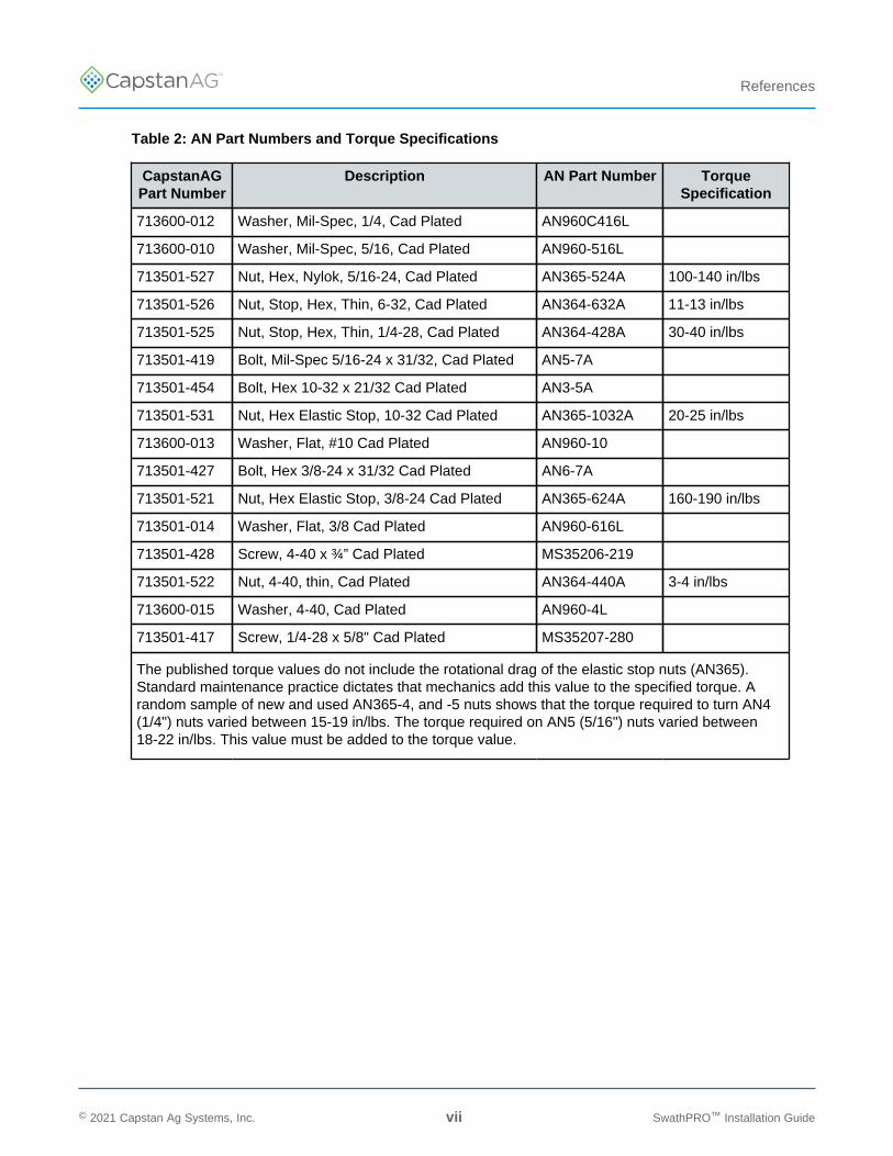
Table 2: AN Part Numbers and Torque Specifications
CapstanAGPart Number
Description AN Part Number TorqueSpecification
713600-012 Washer, Mil-Spec, 1/4, Cad Plated AN960C416L
713600-010 Washer, Mil-Spec, 5/16, Cad Plated AN960-516L
713501-527 Nut, Hex, Nylok, 5/16-24, Cad Plated AN365-524A 100-140 in/lbs
713501-526 Nut, Stop, Hex, Thin, 6-32, Cad Plated AN364-632A 11-13 in/lbs
713501-525 Nut, Stop, Hex, Thin, 1/4-28, Cad Plated AN364-428A 30-40 in/lbs
713501-419 Bolt, Mil-Spec 5/16-24 x 31/32, Cad Plated AN5-7A
713501-454 Bolt, Hex 10-32 x 21/32 Cad Plated AN3-5A
713501-531 Nut, Hex Elastic Stop, 10-32 Cad Plated AN365-1032A 20-25 in/lbs
713600-013 Washer, Flat, #10 Cad Plated AN960-10
713501-427 Bolt, Hex 3/8-24 x 31/32 Cad Plated AN6-7A
713501-521 Nut, Hex Elastic Stop, 3/8-24 Cad Plated AN365-624A 160-190 in/lbs
713501-014 Washer, Flat, 3/8 Cad Plated AN960-616L
713501-428 Screw, 4-40 x ¾” Cad Plated MS35206-219
713501-522 Nut, 4-40, thin, Cad Plated AN364-440A 3-4 in/lbs
713600-015 Washer, 4-40, Cad Plated AN960-4L
713501-417 Screw, 1/4-28 x 5/8" Cad Plated MS35207-280
The published torque values do not include the rotational drag of the elastic stop nuts (AN365).Standard maintenance practice dictates that mechanics add this value to the specified torque. Arandom sample of new and used AN365-4, and -5 nuts shows that the torque required to turn AN4(1/4") nuts varied between 15-19 in/lbs. The torque required on AN5 (5/16") nuts varied between18-22 in/lbs. This value must be added to the torque value.
© 2021 Capstan Ag Systems, Inc. vii SwathPRO™ Installation Guide

TM
References
Table 3: Acronym List
Acronym Description
TPST Triple Pole Single Throw
DPST Double Pole Single Throw
SPST Single Pole Single Throw
VCM Valve Control Module
SDS Safety Data Sheet
PPE Personal Protective Equipment
DTM Deutsch Mini
DT Deutsch
PWM Pulse Width Modulation
LED Light Emitting Diode
CAN Controller Area Network
CB Circuit Breaker
© 2021 Capstan Ag Systems, Inc. viii SwathPRO™ Installation Guide

TM
Introduction
Section 1: Introduction
Topics:
• This Manual• Applicable Aircraft Models• Required and Special Tools
© 2021 Capstan Ag Systems, Inc. 9 SwathPRO™ Installation Guide
TM
Introduction
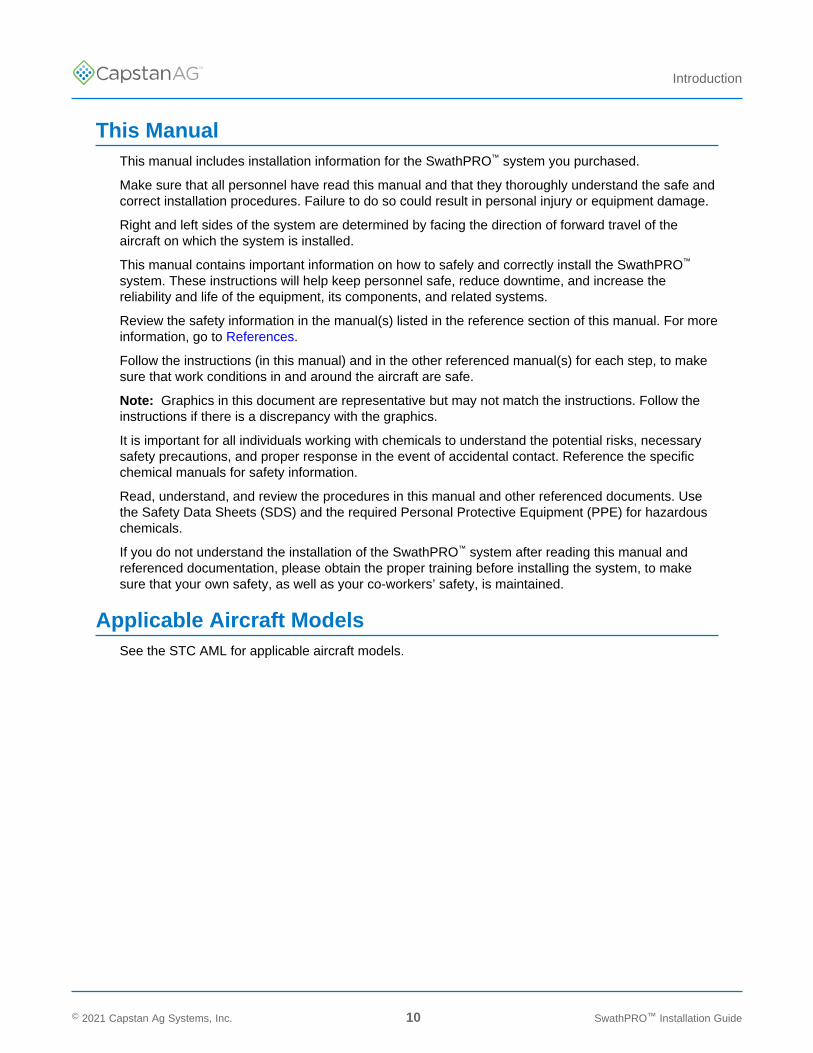
This ManualThis manual includes installation information for the SwathPRO™ system you purchased.
Make sure that all personnel have read this manual and that they thoroughly understand the safe andcorrect installation procedures. Failure to do so could result in personal injury or equipment damage.
Right and left sides of the system are determined by facing the direction of forward travel of theaircraft on which the system is installed.
This manual contains important information on how to safely and correctly install the SwathPRO™
system. These instructions will help keep personnel safe, reduce downtime, and increase thereliability and life of the equipment, its components, and related systems.
Review the safety information in the manual(s) listed in the reference section of this manual. For moreinformation, go to References.
Follow the instructions (in this manual) and in the other referenced manual(s) for each step, to makesure that work conditions in and around the aircraft are safe.
Note: Graphics in this document are representative but may not match the instructions. Follow theinstructions if there is a discrepancy with the graphics.
It is important for all individuals working with chemicals to understand the potential risks, necessarysafety precautions, and proper response in the event of accidental contact. Reference the specificchemical manuals for safety information.
Read, understand, and review the procedures in this manual and other referenced documents. Usethe Safety Data Sheets (SDS) and the required Personal Protective Equipment (PPE) for hazardouschemicals.
If you do not understand the installation of the SwathPRO™ system after reading this manual andreferenced documentation, please obtain the proper training before installing the system, to makesure that your own safety, as well as your co-workers’ safety, is maintained.
Applicable Aircraft ModelsSee the STC AML for applicable aircraft models.
© 2021 Capstan Ag Systems, Inc. 10 SwathPRO™ Installation Guide

TM
Introduction
Required and Special Tools
Tool Description Where Used
Adjustable Stands For the Install the Booms and Boom Hangers
Clamps For the Install the Booms and Boom Hangers
Drill For the Install the Booms and Boom Hangers
Install the Gateway Hub On the Back of theLuggage Compartment
For the Install the Gateway Hub Inside the LuggageCompartment
For the Install the Boom Shutoff Kit
5 psi water line and a camlock fitting on theend of a boom
For the Do the Key Fob Boom Wet Test
Heat Gun For the microswitch in the Install the Boom ShutoffKit
For the Install the Fan Brake Relay Signal Harness(Optional)
Alodine For the Install the Booms and Boom Hangers
© 2021 Capstan Ag Systems, Inc. 11 SwathPRO™ Installation Guide

TM
Introduction
© 2021 Capstan Ag Systems, Inc. 12 SwathPRO™ Installation Guide
This page intentionally left blank

TM
Safety
Section 2: Safety
Topics:
• Signal Words• Emergency Safety• Personal Protective Equipment• Pressurized Fluid Lines• Chemical Safety
© 2021 Capstan Ag Systems, Inc. 13 SwathPRO™ Installation Guide
TM
Safety
Signal WordsDANGER: Indicates an imminent hazard which, if not avoided, will result in death orserious injury. This signal word is limited to the most extreme situations, typically for aircraftcomponents that, for functional purposes, cannot be guarded.
Warning: Indicates a potential hazard which, if not avoided, could result in death or seriousinjury, and includes hazards that are exposed when guards are removed. It may also be usedto alert against unsafe practices.
CAUTION: Indicates a potential hazard which, if not avoided, may result in minor or moderateinjury. It may also be used to alert against unsafe practices.
Important: This is used to draw attention to specific information that is necessary for the operation,setup, or service of the system.
Note: This is used for additional information that can help understand or operate the system.
Emergency SafetyFire extinguishing systems must meet the applicable OSHA requirements, and all users of portable/fixed fire suppression equipment must know the types, limitations, and proper uses of this equipment;including hazards involved with incipient stage firefighting.
Keep emergency numbers for doctors, ambulance service, hospital, and fire department near yourtelephone.
Know the location of fire extinguishers and first aid kits and how to use them.
Examine the fire extinguisher and service the fire extinguisher regularly.
Follow the recommendations on the instructions plate.
Very small fires can be put out (extinguished) with a fire extinguisher. Use an appropriate method toextinguish a fire (water for paper fires, and chemical extinguishers for electrical or chemical fires).
Personal Protective EquipmentWear close-fitting clothing and the correct personal protective equipment (PPE) for the job. See thespecific chemical manufacturer documentation or other information for correct PPE.
Pressurized Fluid LinesDo not heat by welding, soldering, or using a torch near pressurized fluid lines or other flammablematerials. Pressurized lines can accidentally burst when too much heat is present.
Chemical SafetyChemicals used in agricultural applications can be harmful to your health and/or the environment ifnot used correctly. Always follow all label directions for effective, safe, and legal use of agriculturalchemicals.
© 2021 Capstan Ag Systems, Inc. 14 SwathPRO™ Installation Guide
TM
Installation
Section 3: Installation
Topics:
• Prepare for Installation andSetup
• System Layout• Parts List• Before Installation of the
CapstanAG™ System• Install the Booms and Boom
Hangers• Gateway Hub Mounting
Location Options• Install the Circuit Breakers and
Power Harnesses• Install the Pressure Sensor• Install the Gateway Boom
Extension Harnesses• Boom Shutoff Kit Schematic• Install the Servo/Flow Control
Valve Harness• Install the GPS Receiver• Install the CapView• Install the Maneuvering Speed
Placard Decal• Install the Parts to the Center
Boom• Install the Nozzle Tips• Post-install Checklist• Electrical Loads• Weight and Balance
Information• Return to Service
© 2021 Capstan Ag Systems, Inc. 15 SwathPRO™ Installation Guide
TM
Installation
Prepare for Installation and SetupCAUTION: Before installation or service to the system, read and understand the aircraftinstallation and maintenance manuals. Chemical residue may be present on/in the equipment.Use the correct personal protective equipment.
Important: Before installation, make sure that all parts are included in the shipping boxes. Makesure that the parts match the list of parts for your aircraft that is included in the shipping boxes.
Important: Do not attach the harnesses to the aircraft or components with cable ties until the dry testof the system is complete.
Do a check of the system layout and parts list in this manual.
Support harnesses and wiring using the provided cable ties as required to prevent chafing anddamage every 24 inches at a minimum. Make sure that the harnesses and wiring does not interferewith flight control cables or other moving parts.
See Table 2: AN Part Numbers and Torque Specifications for all required torque specifications.
© 2021 Capstan Ag Systems, Inc. 16 SwathPRO™ Installation Guide
TM
Installation
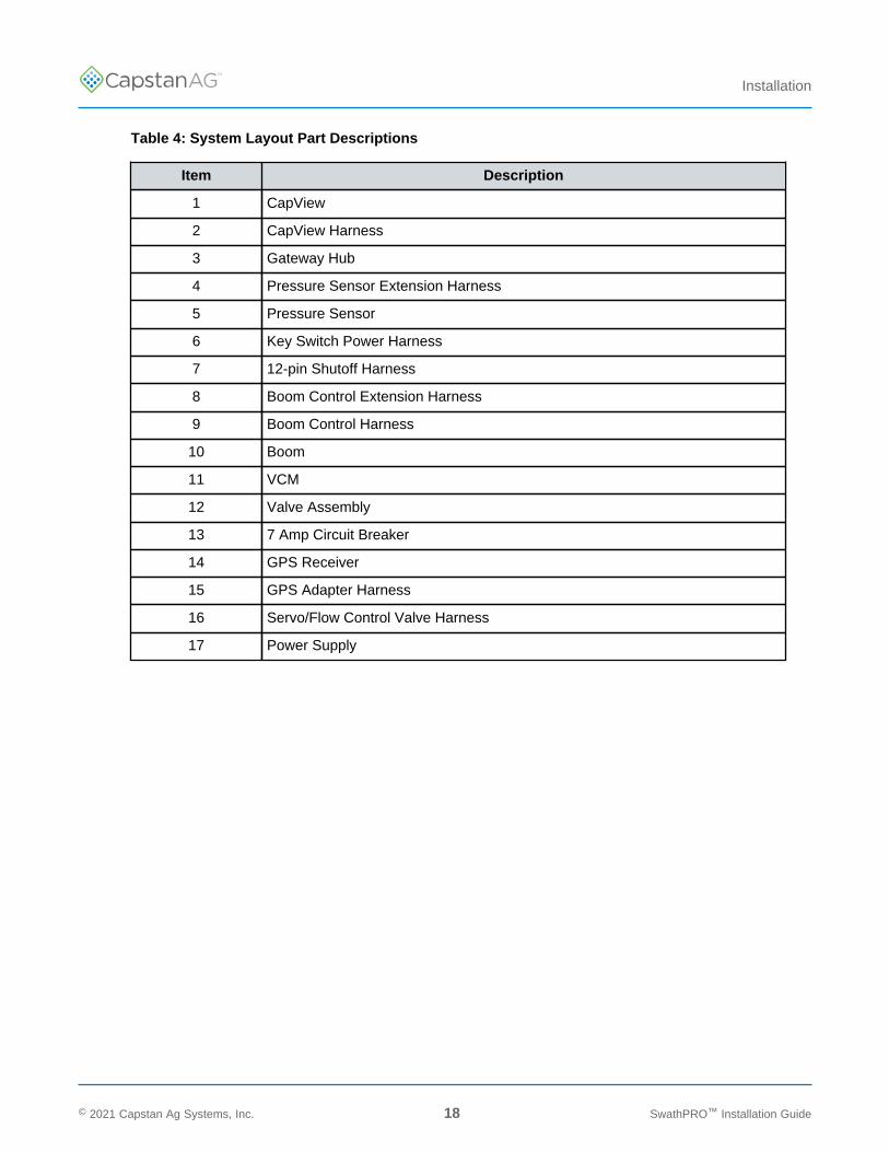
System Layout
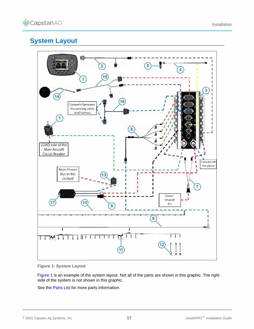
Figure 1: System Layout
Figure 1 is an example of the system layout. Not all of the parts are shown in this graphic. The rightside of the system is not shown in this graphic.
See the Parts List for more parts information.
© 2021 Capstan Ag Systems, Inc. 17 SwathPRO™ Installation Guide
TM
Installation
Table 4: System Layout Part Descriptions
Item Description
1 CapView
2 CapView Harness
3 Gateway Hub
4 Pressure Sensor Extension Harness
5 Pressure Sensor
6 Key Switch Power Harness
7 12-pin Shutoff Harness
8 Boom Control Extension Harness
9 Boom Control Harness
10 Boom
11 VCM
12 Valve Assembly
13 7 Amp Circuit Breaker
14 GPS Receiver
15 GPS Adapter Harness
16 Servo/Flow Control Valve Harness
17 Power Supply
© 2021 Capstan Ag Systems, Inc. 18 SwathPRO™ Installation Guide
TM
Installation
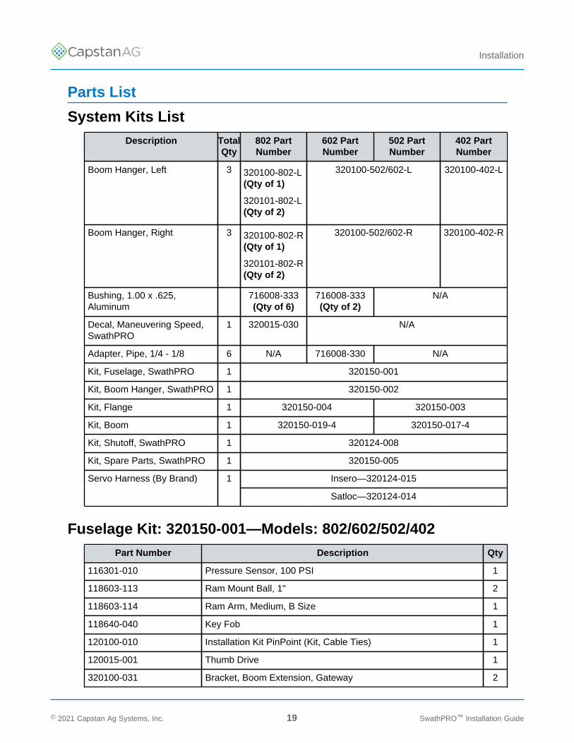
Parts List
System Kits ListDescription Total
Qty802 PartNumber
602 PartNumber
502 PartNumber
402 PartNumber
Boom Hanger, Left 3 320100-802-L(Qty of 1)
320101-802-L(Qty of 2)
320100-502/602-L 320100-402-L
Boom Hanger, Right 3 320100-802-R(Qty of 1)
320101-802-R(Qty of 2)
320100-502/602-R 320100-402-R
Bushing, 1.00 x .625,Aluminum
716008-333(Qty of 6)
716008-333(Qty of 2)
N/A
Decal, Maneuvering Speed,SwathPRO
1 320015-030 N/A
Adapter, Pipe, 1/4 - 1/8 6 N/A 716008-330 N/A
Kit, Fuselage, SwathPRO 1 320150-001
Kit, Boom Hanger, SwathPRO 1 320150-002
Kit, Flange 1 320150-004 320150-003
Kit, Boom 1 320150-019-4 320150-017-4
Kit, Shutoff, SwathPRO 1 320124-008
Kit, Spare Parts, SwathPRO 1 320150-005
Insero—320124-015Servo Harness (By Brand) 1
Satloc—320124-014
Fuselage Kit: 320150-001—Models: 802/602/502/402Part Number Description Qty
116301-010 Pressure Sensor, 100 PSI 1
118603-113 Ram Mount Ball, 1" 2
118603-114 Ram Arm, Medium, B Size 1
118640-040 Key Fob 1
120100-010 Installation Kit PinPoint (Kit, Cable Ties) 1
120015-001 Thumb Drive 1
320100-031 Bracket, Boom Extension, Gateway 2
© 2021 Capstan Ag Systems, Inc. 19 SwathPRO™ Installation Guide
TM
Installation
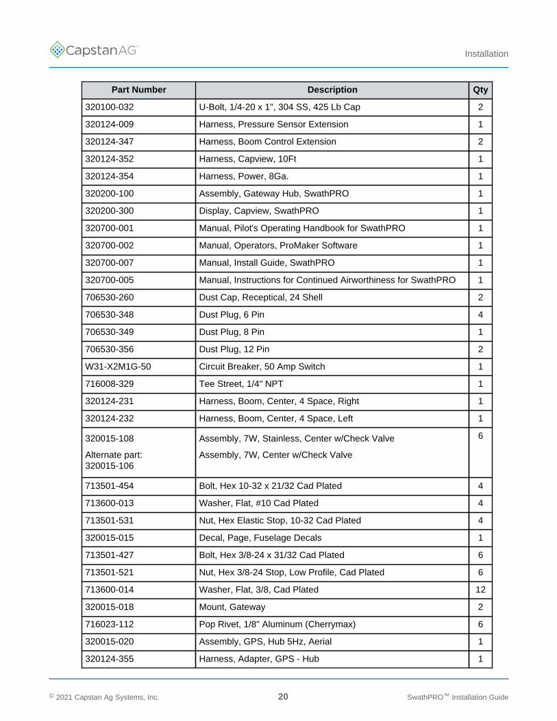
Part Number Description Qty
320100-032 U-Bolt, 1/4-20 x 1", 304 SS, 425 Lb Cap 2
320124-009 Harness, Pressure Sensor Extension 1
320124-347 Harness, Boom Control Extension 2
320124-352 Harness, Capview, 10Ft 1
320124-354 Harness, Power, 8Ga. 1
320200-100 Assembly, Gateway Hub, SwathPRO 1
320200-300 Display, Capview, SwathPRO 1
320700-001 Manual, Pilot's Operating Handbook for SwathPRO 1
320700-002 Manual, Operators, ProMaker Software 1
320700-007 Manual, Install Guide, SwathPRO 1
320700-005 Manual, Instructions for Continued Airworthiness for SwathPRO 1
706530-260 Dust Cap, Receptical, 24 Shell 2
706530-348 Dust Plug, 6 Pin 4
706530-349 Dust Plug, 8 Pin 1
706530-356 Dust Plug, 12 Pin 2
W31-X2M1G-50 Circuit Breaker, 50 Amp Switch 1
716008-329 Tee Street, 1/4" NPT 1
320124-231 Harness, Boom, Center, 4 Space, Right 1
320124-232 Harness, Boom, Center, 4 Space, Left 1
320015-108
Alternate part:320015-106
Assembly, 7W, Stainless, Center w/Check Valve
Assembly, 7W, Center w/Check Valve
6
713501-454 Bolt, Hex 10-32 x 21/32 Cad Plated 4
713600-013 Washer, Flat, #10 Cad Plated 4
713501-531 Nut, Hex Elastic Stop, 10-32 Cad Plated 4
320015-015 Decal, Page, Fuselage Decals 1
713501-427 Bolt, Hex 3/8-24 x 31/32 Cad Plated 6
713501-521 Nut, Hex 3/8-24 Stop, Low Profile, Cad Plated 6
713600-014 Washer, Flat, 3/8, Cad Plated 12
320015-018 Mount, Gateway 2
716023-112 Pop Rivet, 1/8" Aluminum (Cherrymax) 6
320015-020 Assembly, GPS, Hub 5Hz, Aerial 1
320124-355 Harness, Adapter, GPS - Hub 1
© 2021 Capstan Ag Systems, Inc. 20 SwathPRO™ Installation Guide
TM
Installation
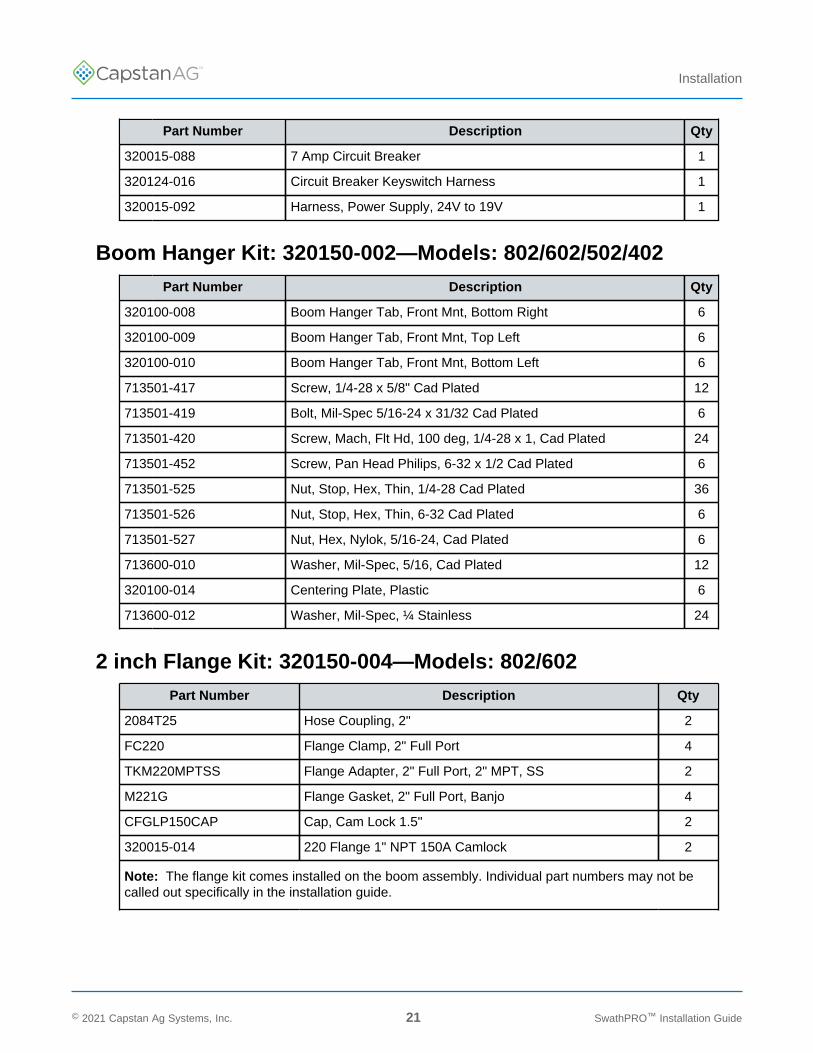
Part Number Description Qty
320015-088 7 Amp Circuit Breaker 1
320124-016 Circuit Breaker Keyswitch Harness 1
320015-092 Harness, Power Supply, 24V to 19V 1
Boom Hanger Kit: 320150-002—Models: 802/602/502/402Part Number Description Qty
320100-008 Boom Hanger Tab, Front Mnt, Bottom Right 6
320100-009 Boom Hanger Tab, Front Mnt, Top Left 6
320100-010 Boom Hanger Tab, Front Mnt, Bottom Left 6
713501-417 Screw, 1/4-28 x 5/8" Cad Plated 12
713501-419 Bolt, Mil-Spec 5/16-24 x 31/32 Cad Plated 6
713501-420 Screw, Mach, Flt Hd, 100 deg, 1/4-28 x 1, Cad Plated 24
713501-452 Screw, Pan Head Philips, 6-32 x 1/2 Cad Plated 6
713501-525 Nut, Stop, Hex, Thin, 1/4-28 Cad Plated 36
713501-526 Nut, Stop, Hex, Thin, 6-32 Cad Plated 6
713501-527 Nut, Hex, Nylok, 5/16-24, Cad Plated 6
713600-010 Washer, Mil-Spec, 5/16, Cad Plated 12
320100-014 Centering Plate, Plastic 6
713600-012 Washer, Mil-Spec, ¼ Stainless 24
2 inch Flange Kit: 320150-004—Models: 802/602Part Number Description Qty
2084T25 Hose Coupling, 2" 2
FC220 Flange Clamp, 2" Full Port 4
TKM220MPTSS Flange Adapter, 2" Full Port, 2" MPT, SS 2
M221G Flange Gasket, 2" Full Port, Banjo 4
CFGLP150CAP Cap, Cam Lock 1.5" 2
320015-014 220 Flange 1" NPT 150A Camlock 2
Note: The flange kit comes installed on the boom assembly. Individual part numbers may not becalled out specifically in the installation guide.
© 2021 Capstan Ag Systems, Inc. 21 SwathPRO™ Installation Guide
TM
Installation
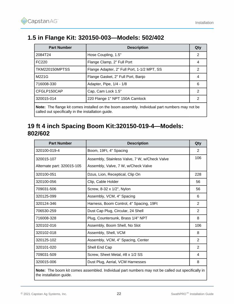
1.5 in Flange Kit: 320150-003—Models: 502/402Part Number Description Qty
2084T24 Hose Coupling, 1.5" 2
FC220 Flange Clamp, 2" Full Port 4
TKM220150MPTSS Flange Adapter, 2" Full Port, 1-1/2 MPT, SS 2
M221G Flange Gasket, 2" Full Port, Banjo 4
716008-330 Adapter, Pipe, 1/4 - 1/8 6
CFGLP150CAP Cap, Cam Lock 1.5" 2
320015-014 220 Flange 1" NPT 150A Camlock 2
Note: The flange kit comes installed on the boom assembly. Individual part numbers may not becalled out specifically in the installation guide.
19 ft 4 inch Spacing Boom Kit:320150-019-4—Models:802/602
Part Number Description Qty
320100-019-4 Boom, 19Ft, 4" Spacing 2
320015-107
Alternate part: 320015-105
Assembly, Stainless Valve, 7 W, w/Check Valve
Assembly, Valve, 7 W, w/Check Valve
106
320100-051 Dzus, Lion, Receptical, Clip On 228
320100-056 Clip, Cable Holder 56
709031-506 Screw, 8-32 x 1/2", Nylon 56
320125-099 Assembly, VCM, 4" Spacing 6
320124-346 Harness, Boom Control, 4" Spacing, 19Ft 2
706530-259 Dust Cap Plug, Circular, 24 Shell 2
716008-328 Plug, Countersunk, Brass 1/4" NPT 8
320102-016 Assembly, Boom Shell, No Slot 106
320102-018 Assembly, Shell, VCM 8
320125-102 Assembly, VCM, 4" Spacing, Center 2
320101-020 Shell End Cap 2
709031-509 Screw, Sheet Metal, #8 x 1/2 SS 4
320015-006 Dust Plug, Aerial, VCM Harnesses 8
Note: The boom kit comes assembled. Individual part numbers may not be called out specifically inthe installation guide.
© 2021 Capstan Ag Systems, Inc. 22 SwathPRO™ Installation Guide
TM
Installation
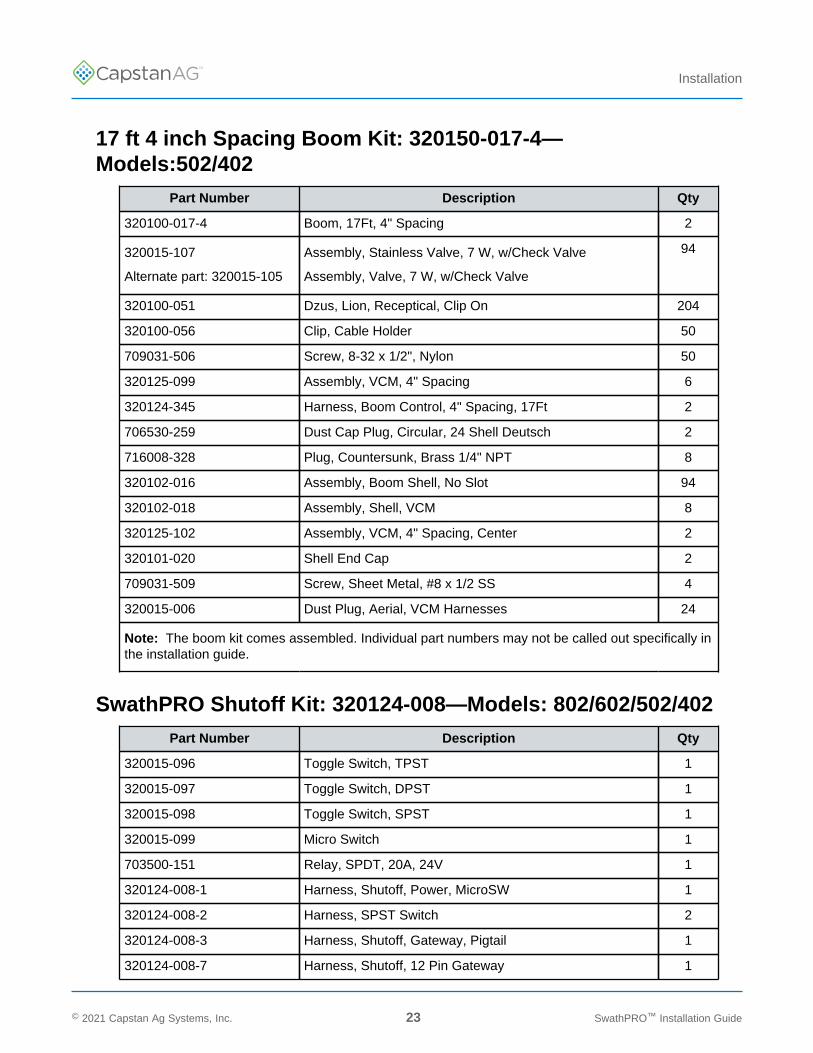
17 ft 4 inch Spacing Boom Kit: 320150-017-4—Models:502/402
Part Number Description Qty
320100-017-4 Boom, 17Ft, 4" Spacing 2
320015-107
Alternate part: 320015-105
Assembly, Stainless Valve, 7 W, w/Check Valve
Assembly, Valve, 7 W, w/Check Valve
94
320100-051 Dzus, Lion, Receptical, Clip On 204
320100-056 Clip, Cable Holder 50
709031-506 Screw, 8-32 x 1/2", Nylon 50
320125-099 Assembly, VCM, 4" Spacing 6
320124-345 Harness, Boom Control, 4" Spacing, 17Ft 2
706530-259 Dust Cap Plug, Circular, 24 Shell Deutsch 2
716008-328 Plug, Countersunk, Brass 1/4" NPT 8
320102-016 Assembly, Boom Shell, No Slot 94
320102-018 Assembly, Shell, VCM 8
320125-102 Assembly, VCM, 4" Spacing, Center 2
320101-020 Shell End Cap 2
709031-509 Screw, Sheet Metal, #8 x 1/2 SS 4
320015-006 Dust Plug, Aerial, VCM Harnesses 24
Note: The boom kit comes assembled. Individual part numbers may not be called out specifically inthe installation guide.
SwathPRO Shutoff Kit: 320124-008—Models: 802/602/502/402Part Number Description Qty
320015-096 Toggle Switch, TPST 1
320015-097 Toggle Switch, DPST 1
320015-098 Toggle Switch, SPST 1
320015-099 Micro Switch 1
703500-151 Relay, SPDT, 20A, 24V 1
320124-008-1 Harness, Shutoff, Power, MicroSW 1
320124-008-2 Harness, SPST Switch 2
320124-008-3 Harness, Shutoff, Gateway, Pigtail 1
320124-008-7 Harness, Shutoff, 12 Pin Gateway 1
© 2021 Capstan Ag Systems, Inc. 23 SwathPRO™ Installation Guide

TM
Installation
Part Number Description Qty
320124-008-8 Harness, Fan Brake Relay, Ground 1
320124-008-9 Harness, Fan Brake Relay, Signal 1
320124-008-10 Harness, Microswitch to Relay 1
715005-156 Sleeve, Solderless 14-16Ga. 3
320015-019 Bracket, Microswitch Mount 1
713501-428 Screw 4-40 x 3/4 Cad Plated 2
713600-015 Washer, Flat, #4, Cad Plated 2
713501-522 Nut, 4-40 Thin, Cad Plated 2
716023-112 Rivet, 1/8 Dia, Aluminum 2
Spare Parts: 320150-005—Models: 802/602/502/402Part Number Description Qty
706530-425 Plug, Dust, 6 Pin DTM 2
705725-137 Fuse, 15A, Type ATO/ATC 4
320102-016 Assy, Boom Shell, No Clip 4
320100-051 Clip On Receptical 8
320015-108
Alternate part: 320015-106
Assembly, 7W, Stainless, Center w/Check Valve
Assembly, 7W, Center w/Check Valve
1
320015-107
Alternate part: 320015-105
Assembly, Stainless Valve, 7 W, w/Check Valve
Assembly, Valve, 7 W, w/Check Valve
4
320025-001 Tool, T35, Valve Body Removal 1
© 2021 Capstan Ag Systems, Inc. 24 SwathPRO™ Installation Guide
TM
Installation
Before Installation of the CapstanAG™ SystemIf the SwathPRO™ system has not been installed on your aircraft before, continue to use thisinstallation guide for correct installation procedures.
If the SwathPRO™ booms have been removed and you are installing the booms again, see theSwathPRO™ Instructions for Continued Airworthiness (ICA) manual for the correct installationprocedures.
1. Make sure that the aircraft key is off.
2. Empty the hopper and clean the spray system and aircraft.
3. Make sure that the aircraft in on a solid, level surface, with the wheels chocked.
4. Remove access shields from the fuselage of the aircraft.
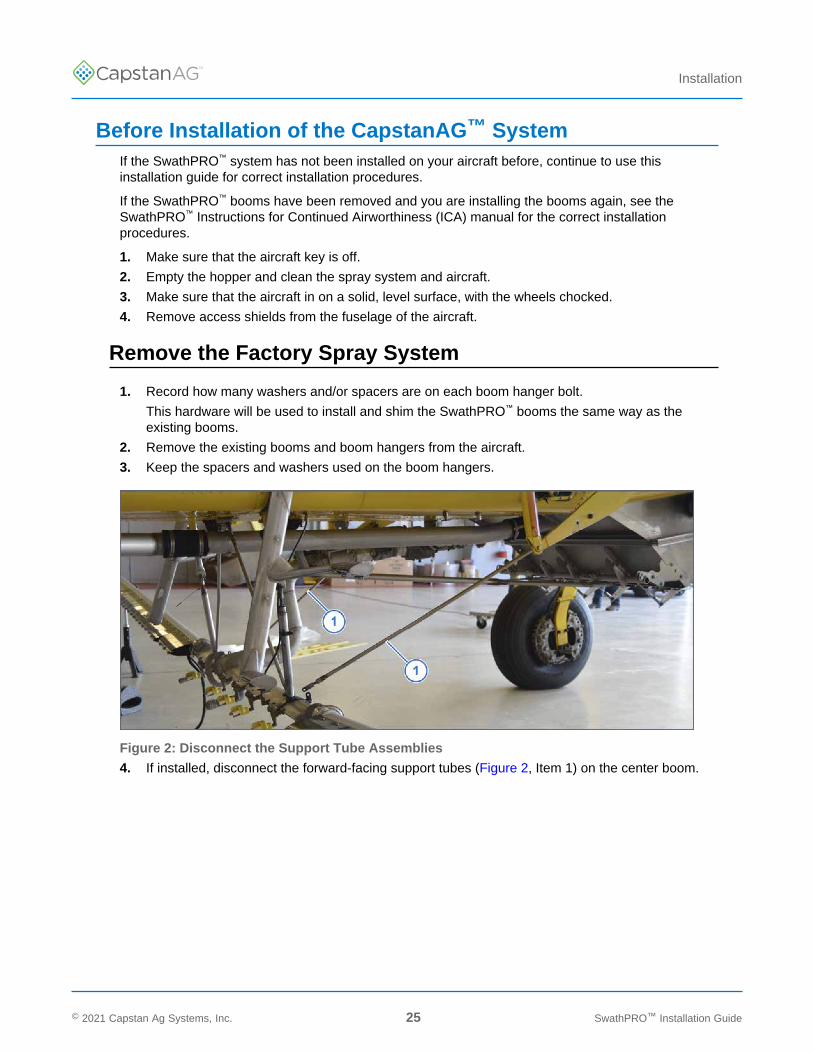
Remove the Factory Spray System
1. Record how many washers and/or spacers are on each boom hanger bolt.
This hardware will be used to install and shim the SwathPRO™ booms the same way as theexisting booms.
2. Remove the existing booms and boom hangers from the aircraft.
3. Keep the spacers and washers used on the boom hangers.
Figure 2: Disconnect the Support Tube Assemblies
4. If installed, disconnect the forward-facing support tubes (Figure 2, Item 1) on the center boom.
© 2021 Capstan Ag Systems, Inc. 25 SwathPRO™ Installation Guide
TM
Installation
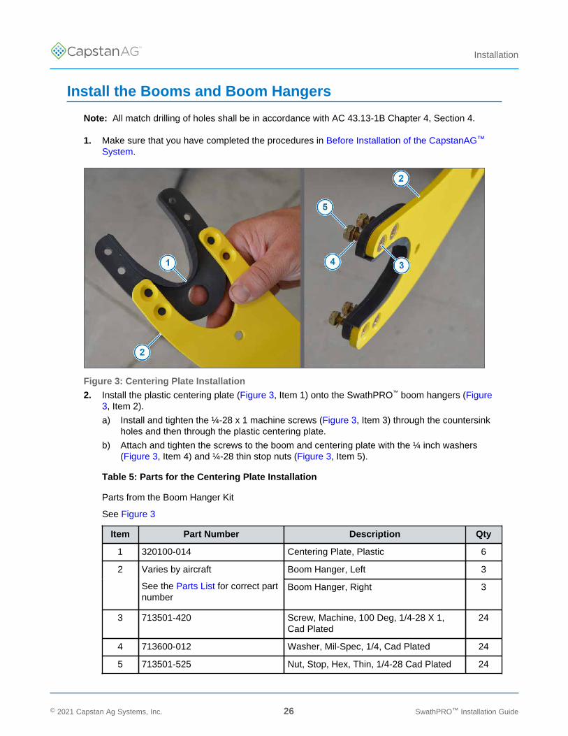
Install the Booms and Boom Hangers
Note: All match drilling of holes shall be in accordance with AC 43.13-1B Chapter 4, Section 4.
1. Make sure that you have completed the procedures in Before Installation of the CapstanAG™
System.
Figure 3: Centering Plate Installation
2. Install the plastic centering plate (Figure 3, Item 1) onto the SwathPRO™ boom hangers (Figure3, Item 2).
a) Install and tighten the ¼-28 x 1 machine screws (Figure 3, Item 3) through the countersinkholes and then through the plastic centering plate.
b) Attach and tighten the screws to the boom and centering plate with the ¼ inch washers(Figure 3, Item 4) and ¼-28 thin stop nuts (Figure 3, Item 5).
Table 5: Parts for the Centering Plate Installation
Parts from the Boom Hanger Kit
See Figure 3
Item Part Number Description Qty
1 320100-014 Centering Plate, Plastic 6
Boom Hanger, Left 32 Varies by aircraft
See the Parts List for correct partnumber
Boom Hanger, Right 3
3 713501-420 Screw, Machine, 100 Deg, 1/4-28 X 1,Cad Plated
24
4 713600-012 Washer, Mil-Spec, 1/4, Cad Plated 24
5 713501-525 Nut, Stop, Hex, Thin, 1/4-28 Cad Plated 24
© 2021 Capstan Ag Systems, Inc. 26 SwathPRO™ Installation Guide
TM
Installation
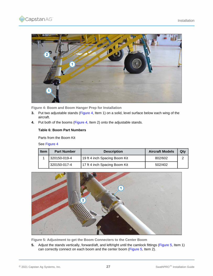
Figure 4: Boom and Boom Hanger Prep for Installation
3. Put two adjustable stands (Figure 4, Item 1) on a solid, level surface below each wing of theaircraft.
4. Put both of the booms (Figure 4, Item 2) onto the adjustable stands.
Table 6: Boom Part Numbers
Parts from the Boom Kit
See Figure 4
Item Part Number Description Aircraft Models Qty
320150-019-4 19 ft 4 inch Spacing Boom Kit 802/6021
320150-017-4 17 ft 4 inch Spacing Boom Kit 502/402
2
Figure 5: Adjustment to get the Boom Connecters to the Center Boom
5. Adjust the stands vertically, forward/aft, and left/right until the camlock fittings (Figure 5, Item 1)can correctly connect on each boom and the center boom (Figure 5, Item 2).
© 2021 Capstan Ag Systems, Inc. 27 SwathPRO™ Installation Guide
TM
Installation
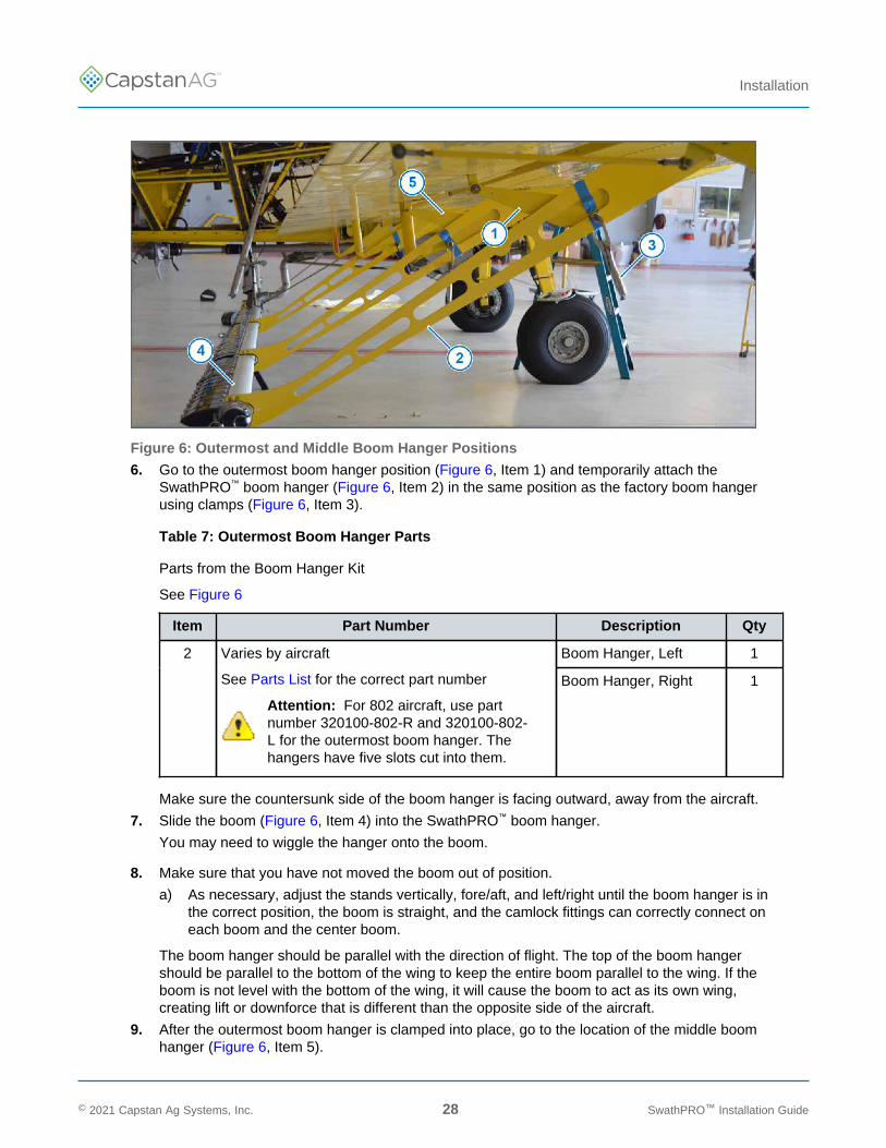
Figure 6: Outermost and Middle Boom Hanger Positions
6. Go to the outermost boom hanger position (Figure 6, Item 1) and temporarily attach theSwathPRO™ boom hanger (Figure 6, Item 2) in the same position as the factory boom hangerusing clamps (Figure 6, Item 3).
Table 7: Outermost Boom Hanger Parts
Parts from the Boom Hanger Kit
See Figure 6
Item Part Number Description Qty
Boom Hanger, Left 12 Varies by aircraft
See Parts List for the correct part number
Attention: For 802 aircraft, use partnumber 320100-802-R and 320100-802-L for the outermost boom hanger. Thehangers have five slots cut into them.
Boom Hanger, Right 1
Make sure the countersunk side of the boom hanger is facing outward, away from the aircraft.
7. Slide the boom (Figure 6, Item 4) into the SwathPRO™ boom hanger.
You may need to wiggle the hanger onto the boom.
8. Make sure that you have not moved the boom out of position.
a) As necessary, adjust the stands vertically, fore/aft, and left/right until the boom hanger is inthe correct position, the boom is straight, and the camlock fittings can correctly connect oneach boom and the center boom.
The boom hanger should be parallel with the direction of flight. The top of the boom hangershould be parallel to the bottom of the wing to keep the entire boom parallel to the wing. If theboom is not level with the bottom of the wing, it will cause the boom to act as its own wing,creating lift or downforce that is different than the opposite side of the aircraft.
9. After the outermost boom hanger is clamped into place, go to the location of the middle boomhanger (Figure 6, Item 5).
© 2021 Capstan Ag Systems, Inc. 28 SwathPRO™ Installation Guide
TM
Installation
The boom hanger is only clamped into place and not fully installed yet. Later in the procedure,the installation of the boom hangers will be completed.
Table 8: Middle Boom Hanger Parts
Parts from the Boom Hanger Kit
See Figure 6
Item Part Number Description Qty
Boom Hanger, Left 15 Varies by aircraft
See Parts List for correct part number
Attention: For 802 aircraft, use partnumber 320101-802-R and 320101-802-Lfor the middle boom hanger. The hangershave four slots cut into them.
Boom Hanger, Right 1
10. Slide the middle boom hanger onto the boom, then clamp it into place.
Make sure that the countersunk side of the hanger is facing outward.
11. Make sure that you have not moved the boom out of position.
a) As necessary, adjust the stands vertically, fore/aft, and left/right until the boom hanger is inthe correct position, the boom is straight, and the camlock fittings can correctly connect oneach boom and the center boom.
The boom hanger should be parallel with the direction of flight. The top of the boom hangershould be parallel to the bottom of the wing to keep the entire boom parallel to the wing. If theboom is not level with the bottom of the wing, it will cause the boom to act as its own wing,creating lift or downforce that is different than the opposite side of the aircraft.
12. After the middle boom hanger is clamped, go to the innermost boom hanger.
The boom hanger is only clamped into place and not fully installed yet. Later in the procedure,the installation of the boom hangers will be completed.
© 2021 Capstan Ag Systems, Inc. 29 SwathPRO™ Installation Guide
TM
Installation
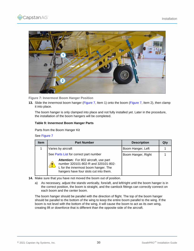
Figure 7: Innermost Boom Hanger Position
13. Slide the innermost boom hanger (Figure 7, Item 1) onto the boom (Figure 7, Item 2), then clampit into place.
The boom hanger is only clamped into place and not fully installed yet. Later in the procedure,the installation of the boom hangers will be completed.
Table 9: Innermost Boom Hanger Parts
Parts from the Boom Hanger Kit
See Figure 7
Item Part Number Description Qty
Boom Hanger, Left 11 Varies by aircraft
See Parts List for correct part number
Attention: For 802 aircraft, use partnumber 320101-802-R and 320101-802-L for the innermost boom hanger. Thehangers have four slots cut into them.
Boom Hanger, Right 1
14. Make sure that you have not moved the boom out of position.
a) As necessary, adjust the stands vertically, fore/aft, and left/right until the boom hanger is inthe correct position, the boom is straight, and the camlock fittings can correctly connect oneach boom and the center boom.
The boom hanger should be parallel with the direction of flight. The top of the boom hangershould be parallel to the bottom of the wing to keep the entire boom parallel to the wing. If theboom is not level with the bottom of the wing, it will cause the boom to act as its own wing,creating lift or downforce that is different than the opposite side of the aircraft.
© 2021 Capstan Ag Systems, Inc. 30 SwathPRO™ Installation Guide
TM
Installation
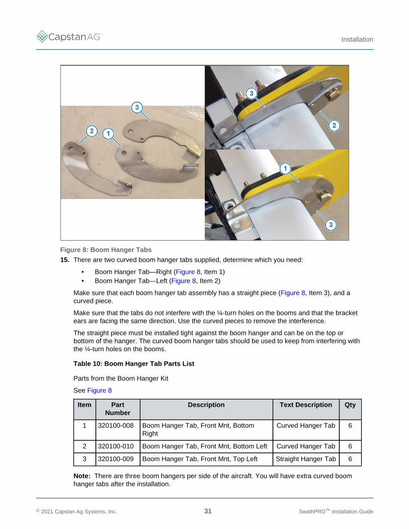
Figure 8: Boom Hanger Tabs
15. There are two curved boom hanger tabs supplied, determine which you need:
• Boom Hanger Tab—Right (Figure 8, Item 1)• Boom Hanger Tab—Left (Figure 8, Item 2)
Make sure that each boom hanger tab assembly has a straight piece (Figure 8, Item 3), and acurved piece.
Make sure that the tabs do not interfere with the ¼-turn holes on the booms and that the bracketears are facing the same direction. Use the curved pieces to remove the interference.
The straight piece must be installed tight against the boom hanger and can be on the top orbottom of the hanger. The curved boom hanger tabs should be used to keep from interfering withthe ¼-turn holes on the booms.
Table 10: Boom Hanger Tab Parts List
Parts from the Boom Hanger Kit
See Figure 8
Item PartNumber
Description Text Description Qty
1 320100-008 Boom Hanger Tab, Front Mnt, BottomRight
Curved Hanger Tab 6
2 320100-010 Boom Hanger Tab, Front Mnt, Bottom Left Curved Hanger Tab 6
3 320100-009 Boom Hanger Tab, Front Mnt, Top Left Straight Hanger Tab 6
Note: There are three boom hangers per side of the aircraft. You will have extra curved boomhanger tabs after the installation.
© 2021 Capstan Ag Systems, Inc. 31 SwathPRO™ Installation Guide
TM
Installation
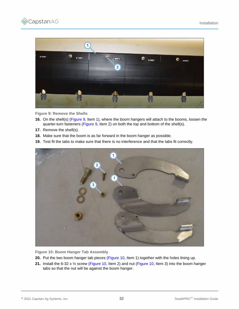
Figure 9: Remove the Shells
16. On the shell(s) (Figure 9, Item 1), where the boom hangers will attach to the booms, loosen thequarter-turn fasteners (Figure 9, Item 2) on both the top and bottom of the shell(s).
17. Remove the shell(s).
18. Make sure that the boom is as far forward in the boom hanger as possible.
19. Test fit the tabs to make sure that there is no interference and that the tabs fit correctly.
Figure 10: Boom Hanger Tab Assembly
20. Put the two boom hanger tab pieces (Figure 10, Item 1) together with the holes lining up.
21. Install the 6-32 x ½ screw (Figure 10, Item 2) and nut (Figure 10, Item 3) into the boom hangertabs so that the nut will be against the boom hanger.
© 2021 Capstan Ag Systems, Inc. 32 SwathPRO™ Installation Guide
TM
Installation
Table 11: Boom Hanger Tab Installation Parts
Parts from the Boom Hanger Kit
See Figure 10
Item Part Number Description Qty
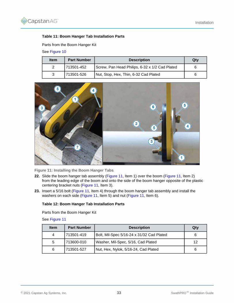
2 713501-452 Screw, Pan Head Philips, 6-32 x 1/2 Cad Plated 6
3 713501-526 Nut, Stop, Hex, Thin, 6-32 Cad Plated 6
Figure 11: Installing the Boom Hanger Tabs
22. Slide the boom hanger tab assembly (Figure 11, Item 1) over the boom (Figure 11, Item 2)from the leading edge of the boom and onto the side of the boom hanger opposite of the plasticcentering bracket nuts (Figure 11, Item 3).
23. Insert a 5/16 bolt (Figure 11, Item 4) through the boom hanger tab assembly and install thewashers on each side (Figure 11, Item 5) and nut (Figure 11, Item 6).
Table 12: Boom Hanger Tab Installation Parts
Parts from the Boom Hanger Kit
See Figure 11
Item Part Number Description Qty
4 713501-419 Bolt, Mil-Spec 5/16-24 x 31/32 Cad Plated 6
5 713600-010 Washer, Mil-Spec, 5/16, Cad Plated 12
6 713501-527 Nut, Hex, Nylok, 5/16-24, Cad Plated 6
© 2021 Capstan Ag Systems, Inc. 33 SwathPRO™ Installation Guide
TM
Installation
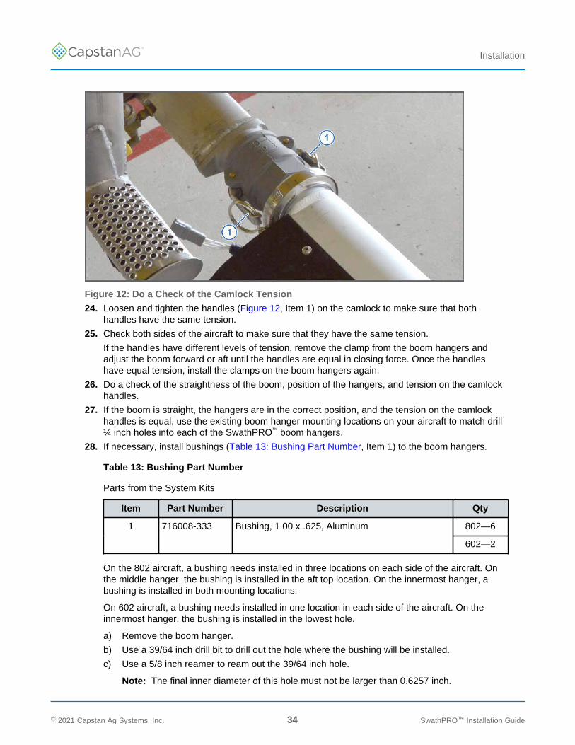
Figure 12: Do a Check of the Camlock Tension
24. Loosen and tighten the handles (Figure 12, Item 1) on the camlock to make sure that bothhandles have the same tension.
25. Check both sides of the aircraft to make sure that they have the same tension.
If the handles have different levels of tension, remove the clamp from the boom hangers andadjust the boom forward or aft until the handles are equal in closing force. Once the handleshave equal tension, install the clamps on the boom hangers again.
26. Do a check of the straightness of the boom, position of the hangers, and tension on the camlockhandles.
27. If the boom is straight, the hangers are in the correct position, and the tension on the camlockhandles is equal, use the existing boom hanger mounting locations on your aircraft to match drill¼ inch holes into each of the SwathPRO™ boom hangers.
28. If necessary, install bushings (Table 13: Bushing Part Number, Item 1) to the boom hangers.
Table 13: Bushing Part Number
Parts from the System Kits
Item Part Number Description Qty
802—61 716008-333 Bushing, 1.00 x .625, Aluminum
602—2
On the 802 aircraft, a bushing needs installed in three locations on each side of the aircraft. Onthe middle hanger, the bushing is installed in the aft top location. On the innermost hanger, abushing is installed in both mounting locations.
On 602 aircraft, a bushing needs installed in one location in each side of the aircraft. On theinnermost hanger, the bushing is installed in the lowest hole.
a) Remove the boom hanger.
b) Use a 39/64 inch drill bit to drill out the hole where the bushing will be installed.
c) Use a 5/8 inch reamer to ream out the 39/64 inch hole.
Note: The final inner diameter of this hole must not be larger than 0.6257 inch.
© 2021 Capstan Ag Systems, Inc. 34 SwathPRO™ Installation Guide
TM
Installation
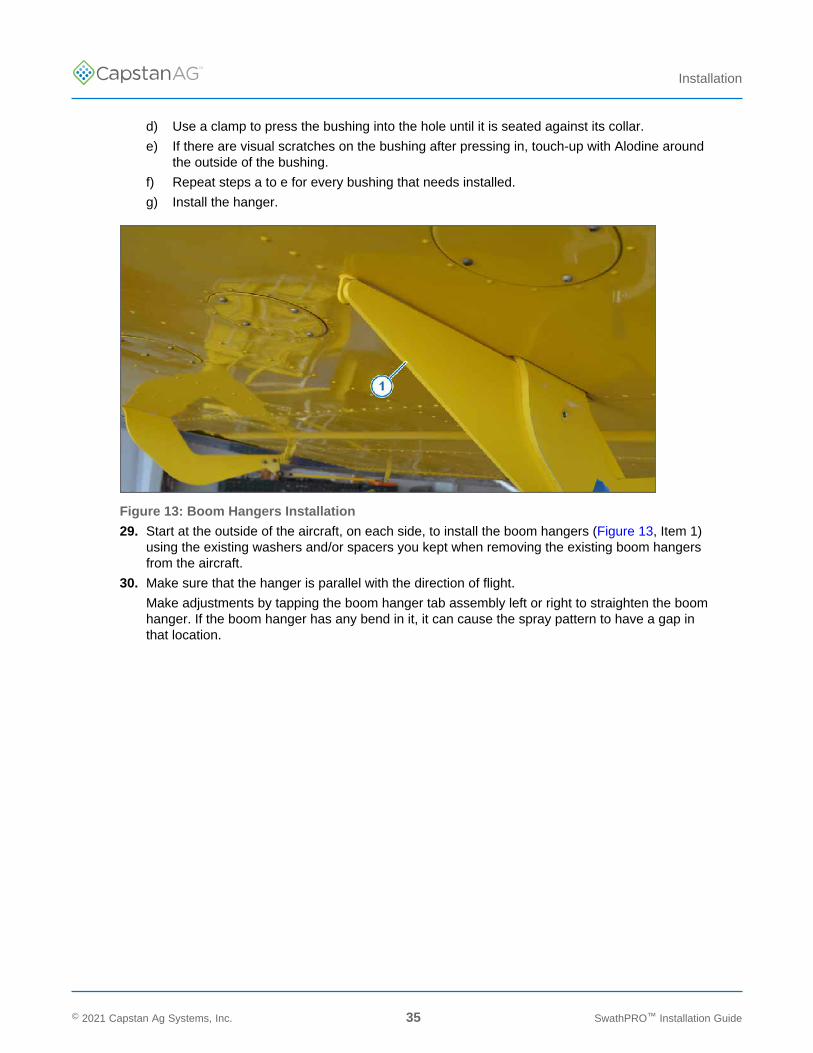
d) Use a clamp to press the bushing into the hole until it is seated against its collar.
e) If there are visual scratches on the bushing after pressing in, touch-up with Alodine aroundthe outside of the bushing.
f) Repeat steps a to e for every bushing that needs installed.
g) Install the hanger.
Figure 13: Boom Hangers Installation
29. Start at the outside of the aircraft, on each side, to install the boom hangers (Figure 13, Item 1)using the existing washers and/or spacers you kept when removing the existing boom hangersfrom the aircraft.
30. Make sure that the hanger is parallel with the direction of flight.
Make adjustments by tapping the boom hanger tab assembly left or right to straighten the boomhanger. If the boom hanger has any bend in it, it can cause the spray pattern to have a gap inthat location.
© 2021 Capstan Ag Systems, Inc. 35 SwathPRO™ Installation Guide
TM
Installation
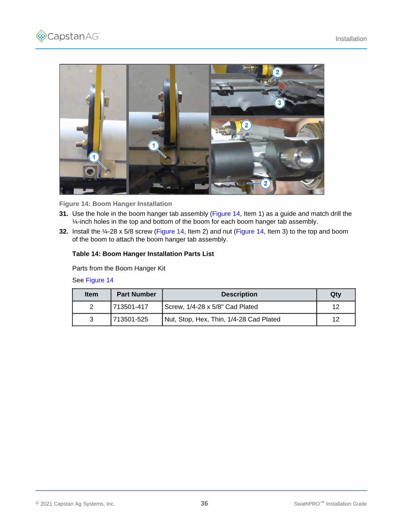
Figure 14: Boom Hanger Installation
31. Use the hole in the boom hanger tab assembly (Figure 14, Item 1) as a guide and match drill the¼-inch holes in the top and bottom of the boom for each boom hanger tab assembly.
32. Install the ¼-28 x 5/8 screw (Figure 14, Item 2) and nut (Figure 14, Item 3) to the top and boomof the boom to attach the boom hanger tab assembly.
Table 14: Boom Hanger Installation Parts List
Parts from the Boom Hanger Kit
See Figure 14
Item Part Number Description Qty
2 713501-417 Screw, 1/4-28 x 5/8" Cad Plated 12
3 713501-525 Nut, Stop, Hex, Thin, 1/4-28 Cad Plated 12
© 2021 Capstan Ag Systems, Inc. 36 SwathPRO™ Installation Guide

TM
Installation
Figure 15: Install the Shells
33. Cut the shells (Figure 15, Item 1) to fit around the boom hanger tab assembly.
34. Install the shells and tighten the quarter-turn fasteners (Figure 15, Item 2)
Figure 16: Forward-facing Support Tubes
35. Attach the forward facing support tubes (Figure 16, Item 1) on the center boom.
You may need to readjust the length of these tubes to get them to fit correctly again.
36. Remove the stands.
© 2021 Capstan Ag Systems, Inc. 37 SwathPRO™ Installation Guide
TM
Installation
Gateway Hub Mounting Location Options
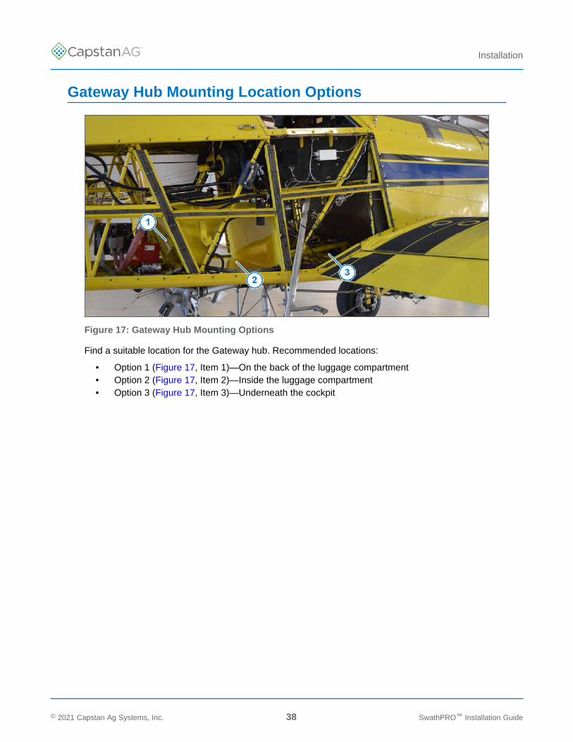
Figure 17: Gateway Hub Mounting Options
Find a suitable location for the Gateway hub. Recommended locations:
• Option 1 (Figure 17, Item 1)—On the back of the luggage compartment• Option 2 (Figure 17, Item 2)—Inside the luggage compartment• Option 3 (Figure 17, Item 3)—Underneath the cockpit
© 2021 Capstan Ag Systems, Inc. 38 SwathPRO™ Installation Guide
TM
Installation
Install the Gateway Hub On the Back of the LuggageCompartment
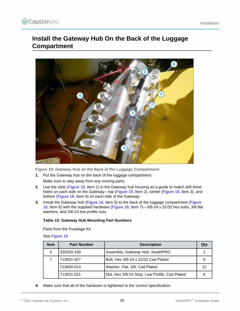
Figure 18: Gateway Hub on the Back of the Luggage Compartment
1. Put the Gateway hub on the back of the luggage compartment.
Make sure to stay away from any moving parts.
2. Use the slots (Figure 18, Item 1) in the Gateway hub housing as a guide to match drill threeholes on each side on the Gateway—top (Figure 18, Item 2), center (Figure 18, Item 3), andbottom (Figure 18, Item 4) on each side of the Gateway.
3. Install the Gateway hub (Figure 18, Item 5) to the back of the luggage compartment (Figure18, Item 6) with the supplied hardware (Figure 18, Item 7)—3/8-24 x 31/32 hex bolts, 3/8 flatwashers, and 3/8-24 low profile nuts.
Table 15: Gateway Hub Mounting Part Numbers
Parts from the Fuselage Kit
See Figure 18
Item Part Number Description Qty
5 320200-100 Assembly, Gateway Hub, SwathPRO 1
713501-427 Bolt, Hex 3/8-24 x 31/32 Cad Plated 6
713600-014 Washer, Flat, 3/8, Cad Plated 12
7
713501-521 Nut, Hex 3/8-24 Stop, Low Profile, Cad Plated 6
4. Make sure that all of the hardware is tightened to the correct specification.
© 2021 Capstan Ag Systems, Inc. 39 SwathPRO™ Installation Guide
TM
Installation
Install the Gateway Hub Inside the Luggage Compartment
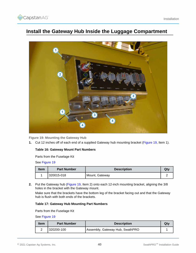
Figure 19: Mounting the Gateway Hub
1. Cut 12 inches off of each end of a supplied Gateway hub mounting bracket (Figure 19, Item 1).
Table 16: Gateway Mount Part Numbers
Parts from the Fuselage Kit
See Figure 19
Item Part Number Description Qty
1 320015-018 Mount, Gateway 2
2. Put the Gateway hub (Figure 19, Item 2) onto each 12-inch mounting bracket, aligning the 3/8holes in the bracket with the Gateway mount.
Make sure that the brackets have the bottom leg of the bracket facing out and that the Gatewayhub is flush with both ends of the brackets.
Table 17: Gateway Hub Mounting Part Numbers
Parts from the Fuselage Kit
See Figure 19
Item Part Number Description Qty
2 320200-100 Assembly, Gateway Hub, SwathPRO 1
© 2021 Capstan Ag Systems, Inc. 40 SwathPRO™ Installation Guide

TM
Installation
3. Install the Gateway hub to the brackets with the supplied hardware (Figure 19, Item 3)—3/8-24 x31/32 hex bolts, 3/8 flat washers, and 3/8-24 low profile nuts.
Table 18: Gateway Hub Mounting Part Numbers
Parts from the Fuselage Kit
See Figure 19
Item Part Number Description Qty
713501-427 Bolt, Hex 3/8-24 x 31/32 Cad Plated 6
713600-014 Washer, Flat, 3/8, Cad Plated 12
3
713501-521 Nut, Hex 3/8-24 Stop, Low Profile, Cad Plated 6
4. Put the Gateway hub with the brackets into the desired location in the luggage compartment.
5. Match drill six locations with a #30 drill bit through the small holes of the mounting bracket
6. Attach the Gateway hub and mounts to the inside of the luggage compartment with the suppliedCherrymax rivets (Figure 19, Item 4).
Table 19: Rivet Part Numbers
Parts from the Fuselage Kit
See Figure 19
Item Part Number Description Qty
4 716023-112 Cherrymax Pop Rivet, 1/8" Aluminum 6
7. Make sure all 3/8 hardware is tightened to the correct specification.
© 2021 Capstan Ag Systems, Inc. 41 SwathPRO™ Installation Guide
TM
Installation
Install the Gateway Hub Underneath the Cockpit
1. Install the Gateway hub onto both of the supplied mounting brackets, aligning the 3/8 holes in thebrackets with the Gateway mount.
Make sure that the brackets have the bottom leg of the bracket facing out.
Table 20: Gateway Hub Mounting Bracket Part Numbers
Parts from the Fuselage Kit
Item Part Number Description Qty
320200-100 Assembly, Gateway Hub, SwathPRO 1
320015-018 Mount, Gateway 2
2. Mount the Gateway hub to the mounts with the supplied hardware—3/8-24 x 31/32 hex bolts, 3/8flat washers, and 3/8-24 low profile nuts.
Table 21: Gateway Hub Mounting Part Numbers
Parts from the Fuselage Kit
Item Part Number Description Qty
713501-427 Bolt, Hex 3/8-24 x 31/32 Cad Plated 6
713600-014 Washer, Flat, 3/8, Cad Plated 12
713501-521 Nut, Hex 3/8-24 Stop, Low Profile, Cad Plated 6
3. Put the Gateway hub with the brackets under the cockpit, and span across the two tubes locatedon the right side of the aircraft.
4. If desired, cut one of the brackets to length.
5. Use four Adel clamps and the supplied hardware— to attach the mounting brackets to the tubes.
Adel clamp sizing:
• MS2191-WDGXX1 for aluminum• MS2191-WSSXX1 for stainless steel
Table 22: Clamp Part Numbers
Parts from the Fuselage Kit
Item Part Number Description Qty
713501-454 Bolt, Hex 10-32 x 21/32 Cad Plated 4
713600-013 Washer, Flat, #10 Cad Plated 4
713501-531 Nut, Hex Elastic Stop, 10-32 Cad Plated 4
6. Make sure that all hardware is tightened to the correct specification.
1 XX is sized as required for mounting structure
© 2021 Capstan Ag Systems, Inc. 42 SwathPRO™ Installation Guide

TM
Installation
Gateway Hub Identification
Figure 20: Gateway Hub Identification
Table 23: Gateway Hub Identification
Item Description Item Description
1 Left Boom Harness Connector Ports 7 Display Harness Connector Port
2 Right Boom Harness Connector Ports 8 Battery Power Harness Terminals
3 Sections 1 to 6 Connector Port 9 Servo Connector Port
4 Sections 7 to 8 Connector Port 10 Flowmeter Port
5 Pressure Connector Port
6 Key Switched Power Connector Port
11 Serial Port
© 2021 Capstan Ag Systems, Inc. 43 SwathPRO™ Installation Guide
TM
Installation
Install the Circuit Breakers and Power Harnesses
Crimp all ring terminals in accordance with AC 43.13-1B Chapter 11, Section 14.
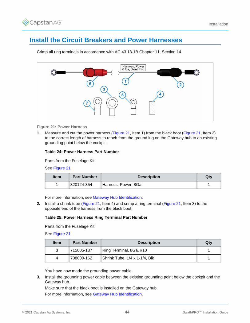
Figure 21: Power Harness
1. Measure and cut the power harness (Figure 21, Item 1) from the black boot (Figure 21, Item 2)to the correct length of harness to reach from the ground lug on the Gateway hub to an existinggrounding point below the cockpit.
Table 24: Power Harness Part Number
Parts from the Fuselage Kit
See Figure 21
Item Part Number Description Qty
1 320124-354 Harness, Power, 8Ga. 1
For more information, see Gateway Hub Identification.
2. Install a shrink tube (Figure 21, Item 4) and crimp a ring terminal (Figure 21, Item 3) to theopposite end of the harness from the black boot.
Table 25: Power Harness Ring Terminal Part Number
Parts from the Fuselage Kit
See Figure 21
Item Part Number Description Qty
3 715005-137 Ring Terminal, 8Ga. #10 1
4 708000-162 Shrink Tube, 1/4 x 1-1/4, Blk 1
You have now made the grounding power cable.
3. Install the grounding power cable between the existing grounding point below the cockpit and theGateway hub.
Make sure that the black boot is installed on the Gateway hub.
For more information, see Gateway Hub Identification.
© 2021 Capstan Ag Systems, Inc. 44 SwathPRO™ Installation Guide
TM
Installation
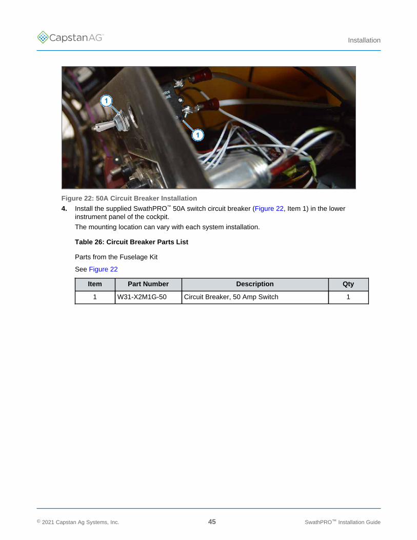
Figure 22: 50A Circuit Breaker Installation
4. Install the supplied SwathPRO™ 50A switch circuit breaker (Figure 22, Item 1) in the lowerinstrument panel of the cockpit.
The mounting location can vary with each system installation.
Table 26: Circuit Breaker Parts List
Parts from the Fuselage Kit
See Figure 22
Item Part Number Description Qty
1 W31-X2M1G-50 Circuit Breaker, 50 Amp Switch 1
© 2021 Capstan Ag Systems, Inc. 45 SwathPRO™ Installation Guide

TM
Installation
Figure 23: Master Circuit Breaker
5. From the bare end of the power harness (Figure 21, Item 1), measure the length of harnessneeded to reach from the 50A circuit breaker to the master circuit breaker (Figure 23, Item 1).
The master circuit breaker for your type of aircraft may be different than the one shown.
6. Cut the correct length of harness and install the shrink tube (Figure 21, Item 4) and crimp the ringterminals (Figure 21, Item 5) to each end of the harness.
Table 27: Ring Terminal Part Number
Parts from the Fuselage Kit, shown in Figure 21
Item Part Number Description Qty
4 708000-162 Shrink Tube, 1/4 x 1-1/4, Blk 2
5 715005-137 Ring Terminal, 8Ga. #10 1
7 715005-136 Ring Terminal, 8Ga. 1/4 1
You have now made the breaker power harness.
7. Install one end of the breaker power harness to the LINE terminal on the back of the 50A circuitbreaker.
8. Install the other end of the breaker power harness to the LOAD terminal on the master circuitbreaker.
9. Measure and cut the power harness from the red boot (Figure 21, Item 1) to the correct length, toreach from the 50A circuit breaker in the cockpit to the power (+) terminal on the Gateway hub.
10. Install a shrink tube (Figure 21, Item 4) and crimp a ring terminal (Figure 21, Item 3) to theopposite end of the harness from the red boot.
© 2021 Capstan Ag Systems, Inc. 46 SwathPRO™ Installation Guide
TM
Installation
Table 28: Power Harness Ring Terminal Part Number
Parts from the Fuselage Kit, shown in Figure 21
Item Part Number Description Qty
3 715005-137 Ring Terminal, 8Ga. #10 1
4 708000-162 Shrink Tube, 1/4 x 1-1/4, Blk 1
11. Connect one end of the circuit power harness to the LOAD terminal on the 50A circuit breakerand the other end of the harness to the power (+) terminal on the Gateway Hub.
Make sure that the red boot is installed on the Gateway hub.
For more information, see Gateway Hub Identification.
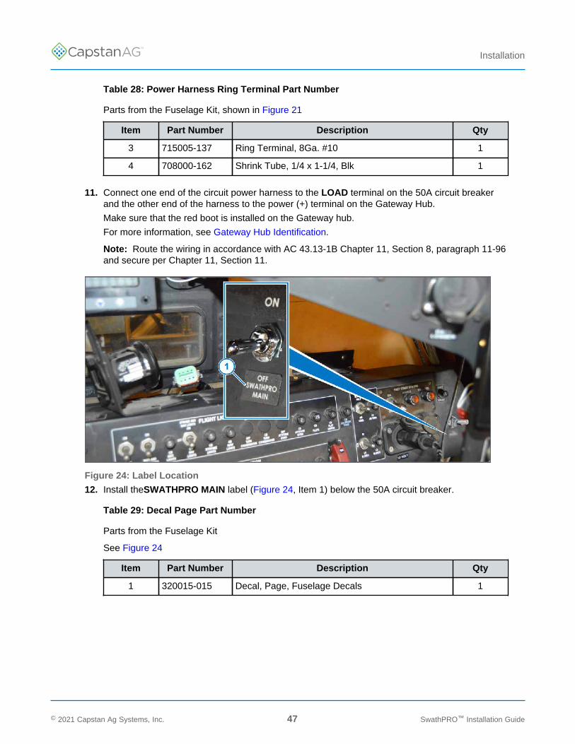
Note: Route the wiring in accordance with AC 43.13-1B Chapter 11, Section 8, paragraph 11-96and secure per Chapter 11, Section 11.
Figure 24: Label Location
12. Install theSWATHPRO MAIN label (Figure 24, Item 1) below the 50A circuit breaker.
Table 29: Decal Page Part Number
Parts from the Fuselage Kit
See Figure 24
Item Part Number Description Qty
1 320015-015 Decal, Page, Fuselage Decals 1
© 2021 Capstan Ag Systems, Inc. 47 SwathPRO™ Installation Guide

TM
Installation
Install Key Switch Power with CapstanAG Power Supply
Figure 25: Circuit Breaker Location Options
Note: Each aircraft is set up differently. Mounting locations can vary with each installation.
1. Make or find an available hole in the lower instrument panel (Figure 25, Item 1) in the cockpit forthe 7A circuit breaker (Figure 25, Item 2).
Table 30: Circuit Breaker Part Number
Parts from the Fuselage Kit
See Figure 25
Item Part Number Description Qty
2 320015-088 7 Amp Circuit Breaker 1
© 2021 Capstan Ag Systems, Inc. 48 SwathPRO™ Installation Guide

TM
Installation
Figure 26: CapstanAG™ Power Supply
2. Mount the power supply (Figure 26, Item 1) near the Gateway Hub (Figure 26, Item 2).
Table 31: Power Supply Part Number
Parts from the Fuselage Kit
See Figure 26
Item Part Number Description Qty
1 320015-092 Harness, Power Supply, 24V to 19V 1
3. Connect the 2-pin DT connector (Figure 26, Item 3), on the blue wire, to the Key Switch port(Figure 26, Item 4) on the Gateway hub.
4. Install the black wire (Figure 26, Item 5) with the ring terminal onto the ground lug (Figure 26,Item 6) on the Gateway hub.
5. Route the red wire (Figure 26, Item 7) to the 7A circuit breaker in the cockpit.
6. Cut off and discard any extra harness length that is not needed to reach the circuit breaker.
7. Crimp a ring terminal onto the end of the red wire.
Table 32: Ring Terminal Part Number
Parts from the Fuselage Kit
Item Part Number Description Qty
715005-151 Ring Terminal, #6, 22-18 Ga. w/Heat Shrink 1
8. Install the ring terminal to one of the terminals on the back of the 7A circuit breaker (Figure 25,Item 2).
© 2021 Capstan Ag Systems, Inc. 49 SwathPRO™ Installation Guide
TM
Installation
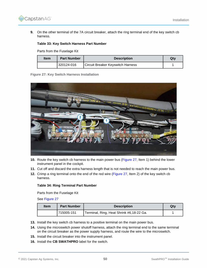
9. On the other terminal of the 7A circuit breaker, attach the ring terminal end of the key switch cbharness.
Table 33: Key Switch Harness Part Number
Parts from the Fuselage Kit
Item Part Number Description Qty
320124-016 Circuit Breaker Keyswitch Harness 1
Figure 27: Key Switch Harness Installation
10. Route the key switch cb harness to the main power bus (Figure 27, Item 1) behind the lowerinstrument panel in the cockpit.
11. Cut off and discard the extra harness length that is not needed to reach the main power bus.
12. Crimp a ring terminal onto the end of the red wire (Figure 27, Item 2) of the key switch cbharness.
Table 34: Ring Terminal Part Number
Parts from the Fuselage Kit
See Figure 27
Item Part Number Description Qty
715005-151 Terminal, Ring, Heat Shrink #6,18-22 Ga. 1
13. Install the key switch cb harness to a positive terminal on the main power bus.
14. Using the microswitch power shutoff harness, attach the ring terminal end to the same terminalon the circuit breaker as the power supply harness, and route the wire to the microswitch.
15. Install the circuit breaker into the instrument panel.
16. Install the CB SWATHPRO label for the switch.
© 2021 Capstan Ag Systems, Inc. 50 SwathPRO™ Installation Guide

TM
Installation
Table 35: Decal Page Part Number
Parts from the Fuselage Kit
Item Part Number Description Qty
320015-015 Decal, Page, Fuselage Decals 1
Install the Pressure Sensor
Figure 28: Existing Pressure Sensor Location
1. Locate the existing pressure sensor on the aircraft.
The usual location is on the right side of the cockpit (Figure 28, Item 1) inside the aircraft frame.
© 2021 Capstan Ag Systems, Inc. 51 SwathPRO™ Installation Guide
TM
Installation
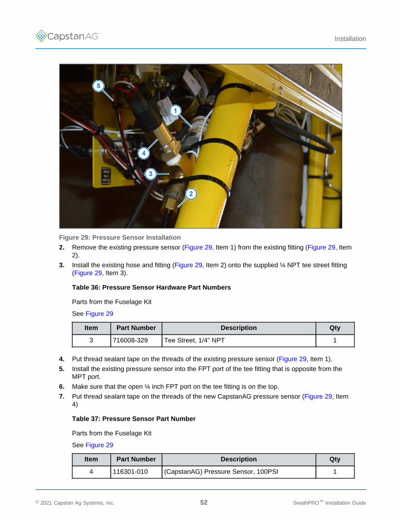
Figure 29: Pressure Sensor Installation
2. Remove the existing pressure sensor (Figure 29, Item 1) from the existing fitting (Figure 29, Item2).
3. Install the existing hose and fitting (Figure 29, Item 2) onto the supplied ¼ NPT tee street fitting(Figure 29, Item 3).
Table 36: Pressure Sensor Hardware Part Numbers
Parts from the Fuselage Kit
See Figure 29
Item Part Number Description Qty
3 716008-329 Tee Street, 1/4" NPT 1
4. Put thread sealant tape on the threads of the existing pressure sensor (Figure 29, Item 1).
5. Install the existing pressure sensor into the FPT port of the tee fitting that is opposite from theMPT port.
6. Make sure that the open ¼ inch FPT port on the tee fitting is on the top.
7. Put thread sealant tape on the threads of the new CapstanAG pressure sensor (Figure 29, Item4)
Table 37: Pressure Sensor Part Number
Parts from the Fuselage Kit
See Figure 29
Item Part Number Description Qty
4 116301-010 (CapstanAG) Pressure Sensor, 100PSI 1
© 2021 Capstan Ag Systems, Inc. 52 SwathPRO™ Installation Guide
TM
Installation
8. Install the new CapstanAG pressure sensor to the tee fitting.
Mount the CapstanAG pressure sensor so that it is leaning back at approximately a 20-degreeangle, or at least vertically.
9. Connect the pressure sensor extension harness (Figure 29, Item 5) to the pressure sensor.
Table 38: Pressure Sensor Harness Part Number
Parts from the Fuselage Kit
See Figure 29
Item Part Number Description Qty
5 320124-009 Harness, Pressure Sensor Extension 1
10. Route the pressure sensor harness to the Gateway hub.
11. Connect the pressure sensor harness to the pressure port on the Gateway hub.
For more information, see Gateway Hub Identification.
Note: Route the wiring in accordance with AC 43.13-1B Chapter 11, Section 8, paragraph 11-96and secure per Chapter 11, Section 11.
Install the Gateway Boom Extension Harnesses
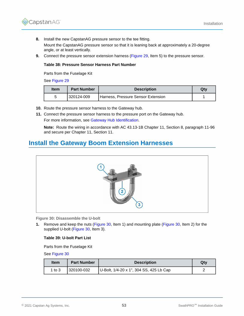
Figure 30: Disassemble the U-bolt
1. Remove and keep the nuts (Figure 30, Item 1) and mounting plate (Figure 30, Item 2) for thesupplied U-bolt (Figure 30, Item 3).
Table 39: U-bolt Part List
Parts from the Fuselage Kit
See Figure 30
Item Part Number Description Qty
1 to 3 320100-032 U-Bolt, 1/4-20 x 1", 304 SS, 425 Lb Cap 2
© 2021 Capstan Ag Systems, Inc. 53 SwathPRO™ Installation Guide

TM
Installation
Figure 31: Bracket Installation
2. Install the bracket (Figure 31, Item 1) to the center boom support (Figure 31, Item 2) on eachside of the aircraft using the U-bolt (Figure 31, Item 3), mounting plate (Figure 31, Item 4), andnuts (Figure 31, Item 5).
Note: The mounting plate may not be required on the larger support tubes. Make sure that youraircraft needs the mounting plate. Discard if not necessary.
Table 40: Bracket Installation Parts List
Parts from the Fuselage Kit
See Figure 31
Item Part Number Description Qty
1 320100-031 Bracket, Boom Extension, Gateway 2
3 to 5 320100-032 U-Bolt, 1/4-20 x 1", 304 SS, 425 Lb Cap 2
3. Remove the plastic nut and washer from the boom control extension harness 31-pin connector(Figure 31, Item 6).
Table 41: Boom Control Extension Harness Part Number
Parts from the Fuselage Kit
See Figure 31
Item Part Number Description Qty
6 320124-347 Harness, Boom Control Extension 2
© 2021 Capstan Ag Systems, Inc. 54 SwathPRO™ Installation Guide
TM
Installation
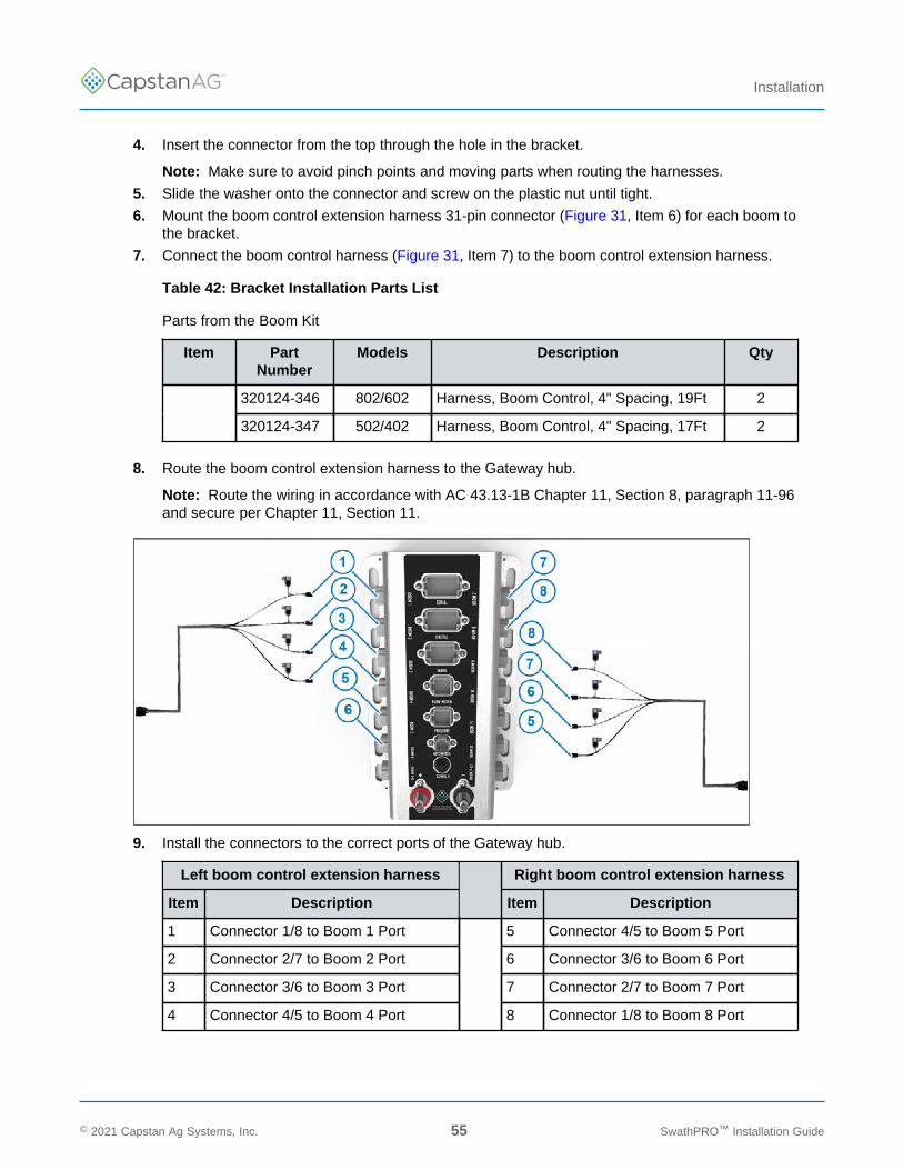
4. Insert the connector from the top through the hole in the bracket.
Note: Make sure to avoid pinch points and moving parts when routing the harnesses.
5. Slide the washer onto the connector and screw on the plastic nut until tight.
6. Mount the boom control extension harness 31-pin connector (Figure 31, Item 6) for each boom tothe bracket.
7. Connect the boom control harness (Figure 31, Item 7) to the boom control extension harness.
Table 42: Bracket Installation Parts List
Parts from the Boom Kit
Item PartNumber
Models Description Qty
320124-346 802/602 Harness, Boom Control, 4" Spacing, 19Ft 2
320124-347 502/402 Harness, Boom Control, 4" Spacing, 17Ft 2
8. Route the boom control extension harness to the Gateway hub.
Note: Route the wiring in accordance with AC 43.13-1B Chapter 11, Section 8, paragraph 11-96and secure per Chapter 11, Section 11.
9. Install the connectors to the correct ports of the Gateway hub.
Left boom control extension harness Right boom control extension harness
Item Description Item Description
1 Connector 1/8 to Boom 1 Port 5 Connector 4/5 to Boom 5 Port
2 Connector 2/7 to Boom 2 Port 6 Connector 3/6 to Boom 6 Port
3 Connector 3/6 to Boom 3 Port 7 Connector 2/7 to Boom 7 Port
4 Connector 4/5 to Boom 4 Port 8 Connector 1/8 to Boom 8 Port
© 2021 Capstan Ag Systems, Inc. 55 SwathPRO™ Installation Guide
TM
Installation
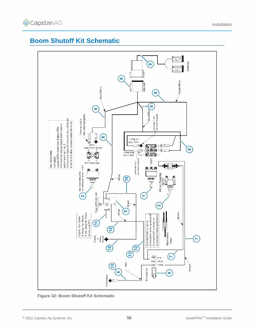
Boom Shutoff Kit Schematic
Figure 32: Boom Shutoff Kit Schematic
© 2021 Capstan Ag Systems, Inc. 56 SwathPRO™ Installation Guide
TM
Installation
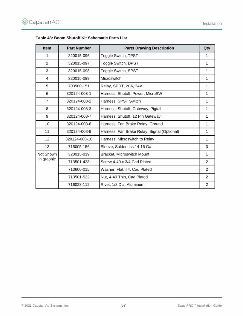
Table 43: Boom Shutoff Kit Schematic Parts List
Item Part Number Parts Drawing Description Qty
1 320015-096 Toggle Switch, TPST 1
2 320015-097 Toggle Switch, DPST 1
3 320015-098 Toggle Switch, SPST 1
4 320015-099 Microswitch 1
5 703500-151 Relay, SPDT, 20A, 24V 1
6 320124-008-1 Harness, Shutoff, Power, MicroSW 1
7 320124-008-2 Harness, SPST Switch 1
8 320124-008-3 Harness, Shutoff, Gateway, Pigtail 1
9 320124-008-7 Harness, Shutoff, 12 Pin Gateway 1
10 320124-008-8 Harness, Fan Brake Relay, Ground 1
11 320124-008-9 Harness, Fan Brake Relay, Signal (Optional) 1
12 320124-008-10 Harness, Microswitch to Relay 1
13 715005-156 Sleeve, Solderless 14-16 Ga. 3
320015-019 Bracket, Microswitch Mount 1
713501-428 Screw 4-40 x 3/4 Cad Plated 2
713600-015 Washer, Flat, #4, Cad Plated 2
713501-522 Nut, 4-40 Thin, Cad Plated 2
Not Shownin graphic
716023-112 Rivet, 1/8 Dia, Aluminum 2
© 2021 Capstan Ag Systems, Inc. 57 SwathPRO™ Installation Guide
TM
Installation
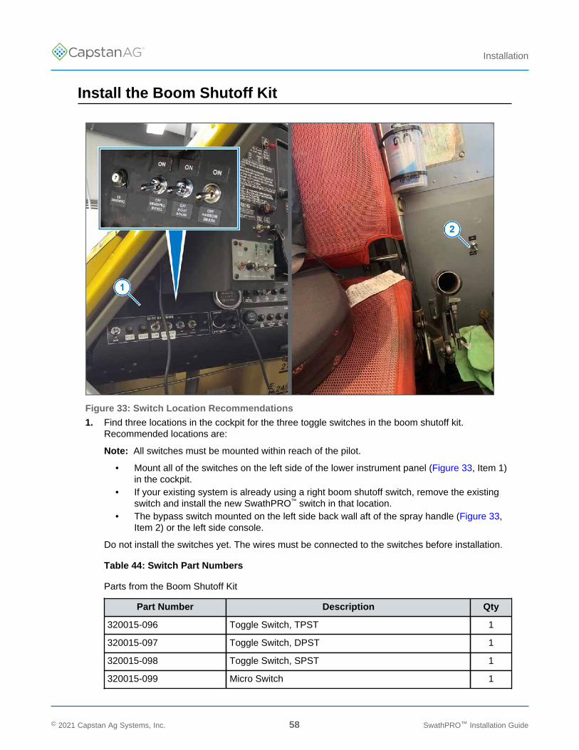
Install the Boom Shutoff Kit
Figure 33: Switch Location Recommendations
1. Find three locations in the cockpit for the three toggle switches in the boom shutoff kit.Recommended locations are:
Note: All switches must be mounted within reach of the pilot.
• Mount all of the switches on the left side of the lower instrument panel (Figure 33, Item 1)in the cockpit.
• If your existing system is already using a right boom shutoff switch, remove the existingswitch and install the new SwathPRO™ switch in that location.
• The bypass switch mounted on the left side back wall aft of the spray handle (Figure 33,Item 2) or the left side console.
Do not install the switches yet. The wires must be connected to the switches before installation.
Table 44: Switch Part Numbers
Parts from the Boom Shutoff Kit
Part Number Description Qty
320015-096 Toggle Switch, TPST 1
320015-097 Toggle Switch, DPST 1
320015-098 Toggle Switch, SPST 1
320015-099 Micro Switch 1
© 2021 Capstan Ag Systems, Inc. 58 SwathPRO™ Installation Guide
TM
Installation
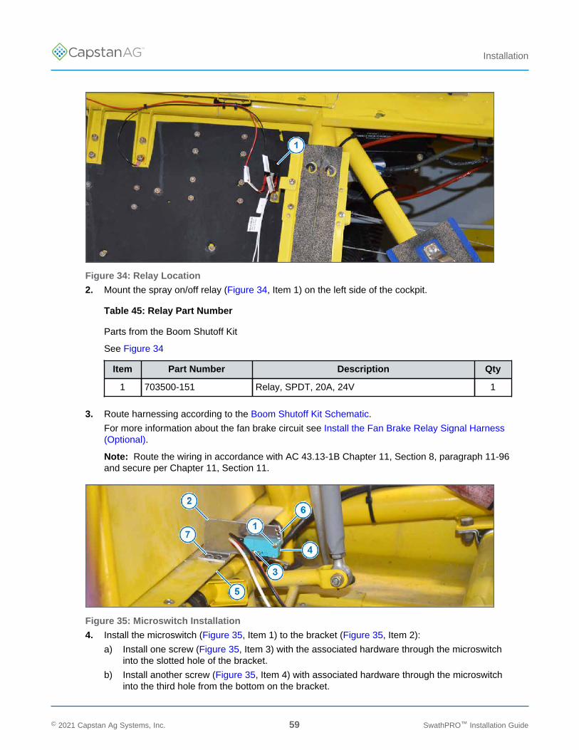
Figure 34: Relay Location
2. Mount the spray on/off relay (Figure 34, Item 1) on the left side of the cockpit.
Table 45: Relay Part Number
Parts from the Boom Shutoff Kit
See Figure 34
Item Part Number Description Qty
1 703500-151 Relay, SPDT, 20A, 24V 1
3. Route harnessing according to the Boom Shutoff Kit Schematic.
For more information about the fan brake circuit see Install the Fan Brake Relay Signal Harness(Optional).
Note: Route the wiring in accordance with AC 43.13-1B Chapter 11, Section 8, paragraph 11-96and secure per Chapter 11, Section 11.
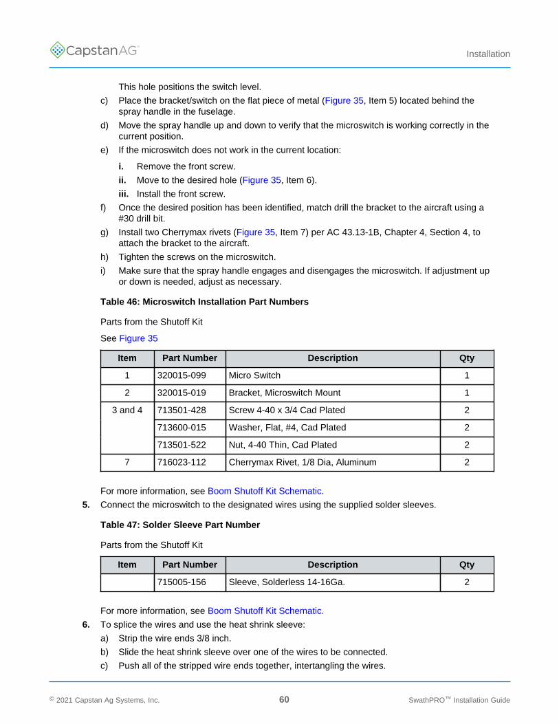
Figure 35: Microswitch Installation
4. Install the microswitch (Figure 35, Item 1) to the bracket (Figure 35, Item 2):
a) Install one screw (Figure 35, Item 3) with the associated hardware through the microswitchinto the slotted hole of the bracket.
b) Install another screw (Figure 35, Item 4) with associated hardware through the microswitchinto the third hole from the bottom on the bracket.
© 2021 Capstan Ag Systems, Inc. 59 SwathPRO™ Installation Guide
TM
Installation
This hole positions the switch level.
c) Place the bracket/switch on the flat piece of metal (Figure 35, Item 5) located behind thespray handle in the fuselage.
d) Move the spray handle up and down to verify that the microswitch is working correctly in thecurrent position.
e) If the microswitch does not work in the current location:
i. Remove the front screw.
ii. Move to the desired hole (Figure 35, Item 6).
iii. Install the front screw.
f) Once the desired position has been identified, match drill the bracket to the aircraft using a#30 drill bit.
g) Install two Cherrymax rivets (Figure 35, Item 7) per AC 43.13-1B, Chapter 4, Section 4, toattach the bracket to the aircraft.
h) Tighten the screws on the microswitch.
i) Make sure that the spray handle engages and disengages the microswitch. If adjustment upor down is needed, adjust as necessary.
Table 46: Microswitch Installation Part Numbers
Parts from the Shutoff Kit
See Figure 35
Item Part Number Description Qty
1 320015-099 Micro Switch 1
2 320015-019 Bracket, Microswitch Mount 1
713501-428 Screw 4-40 x 3/4 Cad Plated 2
713600-015 Washer, Flat, #4, Cad Plated 2
3 and 4
713501-522 Nut, 4-40 Thin, Cad Plated 2
7 716023-112 Cherrymax Rivet, 1/8 Dia, Aluminum 2
For more information, see Boom Shutoff Kit Schematic.
5. Connect the microswitch to the designated wires using the supplied solder sleeves.
Table 47: Solder Sleeve Part Number
Parts from the Shutoff Kit
Item Part Number Description Qty
715005-156 Sleeve, Solderless 14-16Ga. 2
For more information, see Boom Shutoff Kit Schematic.
6. To splice the wires and use the heat shrink sleeve:
a) Strip the wire ends 3/8 inch.
b) Slide the heat shrink sleeve over one of the wires to be connected.
c) Push all of the stripped wire ends together, intertangling the wires.
© 2021 Capstan Ag Systems, Inc. 60 SwathPRO™ Installation Guide
TM
Installation
d) Position the heat shrink sleeve over the mat-ed wires. The internal solder stripe should becentered over stripped section of wires.
e) Use a heat gun to apply heat in the center moving to both ends of the sleeve. Continue untilthe solder has flowed into the wires and the sleeve is tight to the wire. Use caution, do notoverheat and melt the sleeve.
f) Let the heat shrink sleeve cool before handling.
7. Route the harnessing for the right boom shutoff, narrow swath, and bypass switches into thecockpit.
Note: Route the wiring in accordance with AC 43.13-1B Chapter 11, Section 8, paragraph 11-96and secure per Chapter 11, Section 11.
For more information, see Boom Shutoff Kit Schematic.
8. Cut off and discard the extra harness length that is not needed to reach the correct switches.
9. Crimp a ring terminal onto the end of all the wires that are being used.
Table 48: Ring Terminal Part Number
Parts from the Fuselage Kit
See Boom Shutoff Kit Schematic
Item Part Number Description Qty
715005-151 Terminal, Ring, Heat Shrink #6,18-22 Ga. 1
10. Connect the designated harness to the correct switch.
11. Install the shutoff kit harnesses, as shown in Figure 32, Items 7, 8, and 9.
12. Connect the boom section harnesses to the correct port on the Gateway hub:
• Left boom section harness to Boom 1-6• Right boom section harness to Boom 7-12
For more information, see Gateway Hub Identification.
13. Install the switches into the desired locations in the cockpit.
14. Install the on and off labels, as shown in Figure 33.
• SPST switch—SWATHPRO BYPASS• TPST switch—NARROW SWATH• DPST switch—RIGHT BOOM
Table 49: Decal Page Part Number
Parts from the Fuselage Kit
Item Part Number Description Qty
320015-015 Decal, Page, Fuselage Decals 1
© 2021 Capstan Ag Systems, Inc. 61 SwathPRO™ Installation Guide
TM
Installation
Install the Fan Brake Relay Signal Harness (Optional)
Note: The fan brake relay ground harness (Figure 32, Item 10) is required and must be installed,even if the fan brake relay signal harness is not.
1. If the aircraft has an unmodified fan brake circuit:
a) Trace the signal wire from the fan brake switch in the cockpit until the wire exits the cockpit.
b) Cut the wire.
c) With the aircraft power key switch on, verify the wire from the switch has 24V when in thespray off position and 0V when in the spray on position.
d) Splice the two wires back together with the fan brake signal harness (Figure 32, Item 11)added into the splice (3 wires total).
i. Strip the wire ends 3/8 inch.
ii. Slide the heat shrink sleeve over one of the wires to be connected.
iii. Push all of the stripped wire ends together, intertangling the wires.
iv. Position the heat shrink sleeve over the mat-ed wires. The internal solder stripe shouldbe centered over stripped section of wires.
v. Use a heat gun to apply heat in the center moving to both ends of the sleeve. Continueuntil the solder has flowed into the wires and the sleeve is tight to the wire. Use caution,do not overheat and melt the sleeve.
vi. Let the heat shrink sleeve cool before handling.
2. If the fan brake circuit has been modified with relays or an autoboom kit:
a) Attach the fan brake signal harness (Figure 32, Item 11) to any point where there is 24Vwhen in the spray off position and 0V in the spray on position.
3. If the fan brake signal harness (Figure 32, Item 11) is not to be installed, the system will onlybe able to be operated via the microswitch or the bypass switch, and it will not be able to becontrolled by a fan brake switch, autoboom kit, or other relay.
Note: Route the wiring in accordance with AC 43.13-1B Chapter 11, Section 8, paragraph 11-96and secure per Chapter 11, Section 11.
© 2021 Capstan Ag Systems, Inc. 62 SwathPRO™ Installation Guide
TM
Installation
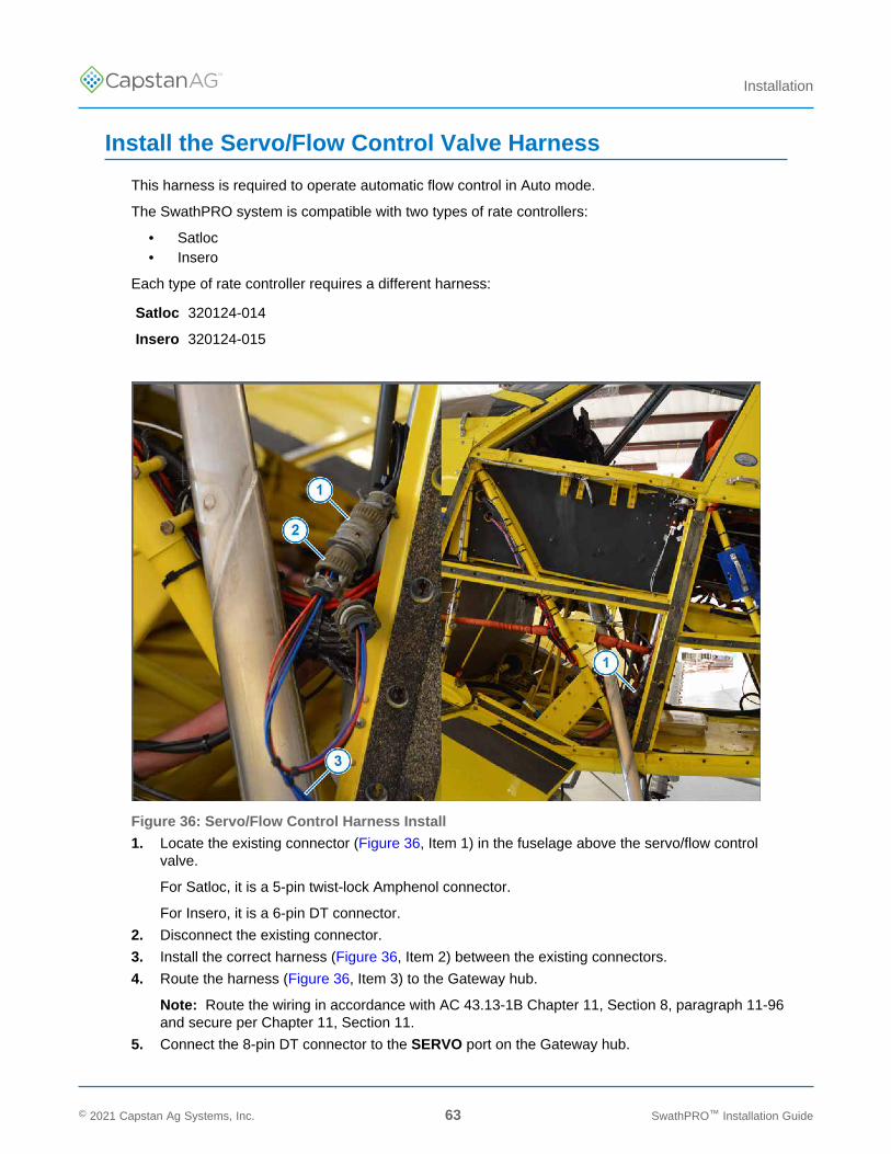
Install the Servo/Flow Control Valve Harness
This harness is required to operate automatic flow control in Auto mode.
The SwathPRO system is compatible with two types of rate controllers:
• Satloc• Insero
Each type of rate controller requires a different harness:
Satloc 320124-014
Insero 320124-015
Figure 36: Servo/Flow Control Harness Install
1. Locate the existing connector (Figure 36, Item 1) in the fuselage above the servo/flow controlvalve.
For Satloc, it is a 5-pin twist-lock Amphenol connector.
For Insero, it is a 6-pin DT connector.
2. Disconnect the existing connector.
3. Install the correct harness (Figure 36, Item 2) between the existing connectors.
4. Route the harness (Figure 36, Item 3) to the Gateway hub.
Note: Route the wiring in accordance with AC 43.13-1B Chapter 11, Section 8, paragraph 11-96and secure per Chapter 11, Section 11.
5. Connect the 8-pin DT connector to the SERVO port on the Gateway hub.
© 2021 Capstan Ag Systems, Inc. 63 SwathPRO™ Installation Guide
TM
Installation
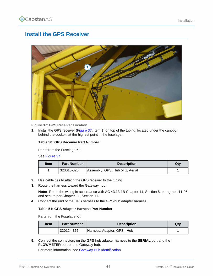
Install the GPS Receiver
Figure 37: GPS Receiver Location
1. Install the GPS receiver (Figure 37, Item 1) on top of the tubing, located under the canopy,behind the cockpit, at the highest point in the fuselage.
Table 50: GPS Receiver Part Number
Parts from the Fuselage Kit
See Figure 37
Item Part Number Description Qty
1 320015-020 Assembly, GPS, Hub 5Hz, Aerial 1
2. Use cable ties to attach the GPS receiver to the tubing.
3. Route the harness toward the Gateway hub.
Note: Route the wiring in accordance with AC 43.13-1B Chapter 11, Section 8, paragraph 11-96and secure per Chapter 11, Section 11.
4. Connect the end of the GPS harness to the GPS-hub adapter harness.
Table 51: GPS Adapter Harness Part Number
Parts from the Fuselage Kit
Item Part Number Description Qty
320124-355 Harness, Adapter, GPS - Hub 1
5. Connect the connectors on the GPS-hub adapter harness to the SERIAL port and theFLOWMETER port on the Gateway hub.
For more information, see Gateway Hub Identification.
© 2021 Capstan Ag Systems, Inc. 64 SwathPRO™ Installation Guide
TM
Installation
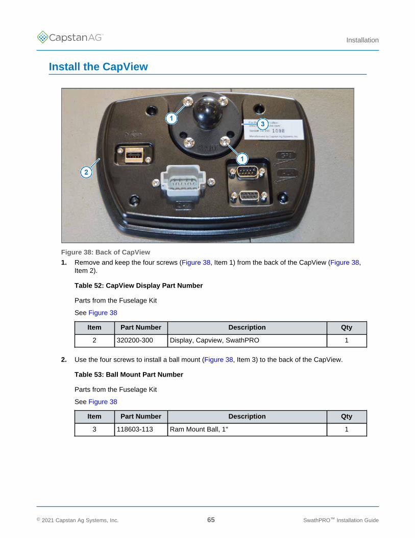
Install the CapView
Figure 38: Back of CapView
1. Remove and keep the four screws (Figure 38, Item 1) from the back of the CapView (Figure 38,Item 2).
Table 52: CapView Display Part Number
Parts from the Fuselage Kit
See Figure 38
Item Part Number Description Qty
2 320200-300 Display, Capview, SwathPRO 1
2. Use the four screws to install a ball mount (Figure 38, Item 3) to the back of the CapView.
Table 53: Ball Mount Part Number
Parts from the Fuselage Kit
See Figure 38
Item Part Number Description Qty
3 118603-113 Ram Mount Ball, 1" 1
© 2021 Capstan Ag Systems, Inc. 65 SwathPRO™ Installation Guide

TM
Installation
3. Install the CapView harness to the Boom 12 port on the Gateway hub.
Table 54: CapView Harness Part Number
Parts from the Fuselage Kit
Item Part Number Description Qty
320124-352 Harness, Capview, 10Ft 1
For more information, see Gateway Hub Identification.
4. Route the CapView harness from the Gateway hub into the cockpit.
Note: The 8-pin connector may need to be removed from the display harness to get it into thecockpit. Take a picture or record the pin locations before removing any wires from the connector.
Note: Route the wiring in accordance with AC 43.13-1B Chapter 11, Section 8, paragraph 11-96and secure per Chapter 11, Section 11.
Figure 39: CapView Mounting Location
5. In the cockpit of the aircraft, find the best location for the CapView (Figure 39, Item 1).
Note: The CapView needs to have a clear line of sight and within reach of the pilot. TheCapView also needs to allow the lower instrument panel to fold down.
The CapView installation location recommendations include:
a. Mounted on the face of the lower instrument panel as far to the right or left as possible.
© 2021 Capstan Ag Systems, Inc. 66 SwathPRO™ Installation Guide
TM
Installation
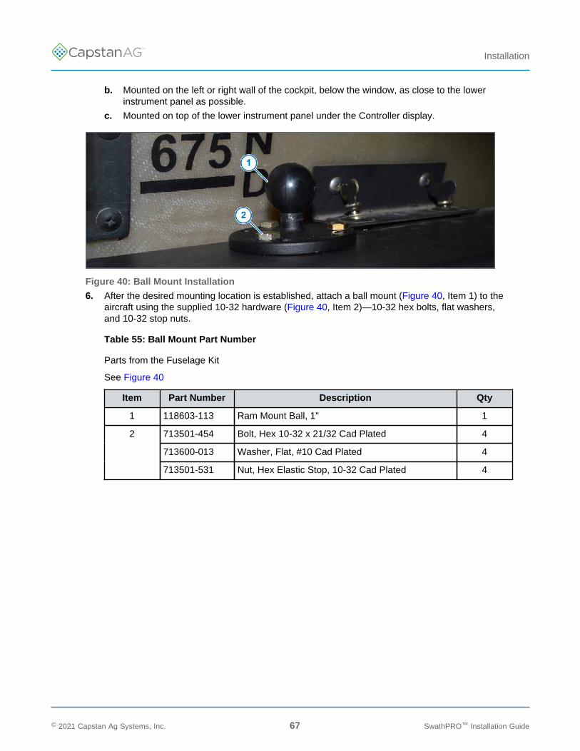
b. Mounted on the left or right wall of the cockpit, below the window, as close to the lowerinstrument panel as possible.
c. Mounted on top of the lower instrument panel under the Controller display.
Figure 40: Ball Mount Installation
6. After the desired mounting location is established, attach a ball mount (Figure 40, Item 1) to theaircraft using the supplied 10-32 hardware (Figure 40, Item 2)—10-32 hex bolts, flat washers,and 10-32 stop nuts.
Table 55: Ball Mount Part Number
Parts from the Fuselage Kit
See Figure 40
Item Part Number Description Qty
1 118603-113 Ram Mount Ball, 1" 1
713501-454 Bolt, Hex 10-32 x 21/32 Cad Plated 4
713600-013 Washer, Flat, #10 Cad Plated 4
2
713501-531 Nut, Hex Elastic Stop, 10-32 Cad Plated 4
© 2021 Capstan Ag Systems, Inc. 67 SwathPRO™ Installation Guide
TM
Installation
Figure 41: Install the CapView
7. Connect the CapView harness (Figure 41, Item 1) into the back of the CapView (Figure 41, Item2).
8. Install one end of the clamp (Figure 41, Item 3) onto the ball mount (Figure 41, Item 4) on theback of the CapView, and the other onto the ball mount attached to the aircraft.
Table 56: RAM Arm Clamp Part Number
Parts from the Fuselage Kit
See Figure 40
Item Part Number Description Qty
118603-114 Ram Arm, Medium, B Size 1
9. Remove the screen protector from the CapView screen.
© 2021 Capstan Ag Systems, Inc. 68 SwathPRO™ Installation Guide

TM
Installation
Install the Maneuvering Speed Placard Decal
Attention: Do not remove the existing maneuvering speed placard.
Important: Must be installed ONLY on an 802 aircraft.
1. Select the correct maneuvering speed placard decal for the aircraft's serial number, from theprovided maneuvering speed decal.
2. Mount as close to the existing maneuvering speed placard, which is close to the airspeedindicator.
Install the Parts to the Center Boom
1. If the operator will have valves on the center boom, go to Step 3.
Figure 42: Dust Plug Installation
2. If the operator chooses not to use any center boom valves:
a) Install the 6-pin DTM dust plug (Figure 42, Item 1) into the 6-pin DTM connector (Figure 42,Item 2) on the left and right center VCM harnesses.
Table 57: Center Valve Part Number
Parts from the Spare Parts Kit
See Figure 42
Item Part Number Description Qty
1 706530-425 Plug, Dust, 6 Pin DTM 2
b) Route the VCM harnesses (Figure 42, Item 3) back along the booms inside the shells.
c) Go directly to Install the Nozzle Tips.
© 2021 Capstan Ag Systems, Inc. 69 SwathPRO™ Installation Guide
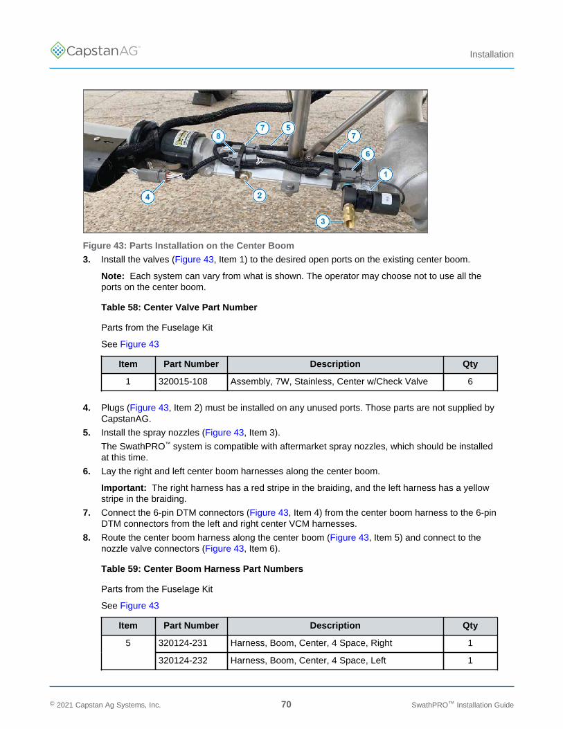
TM
Installation
Figure 43: Parts Installation on the Center Boom
3. Install the valves (Figure 43, Item 1) to the desired open ports on the existing center boom.
Note: Each system can vary from what is shown. The operator may choose not to use all theports on the center boom.
Table 58: Center Valve Part Number
Parts from the Fuselage Kit
See Figure 43
Item Part Number Description Qty
1 320015-108 Assembly, 7W, Stainless, Center w/Check Valve 6
4. Plugs (Figure 43, Item 2) must be installed on any unused ports. Those parts are not supplied byCapstanAG.
5. Install the spray nozzles (Figure 43, Item 3).
The SwathPRO™ system is compatible with aftermarket spray nozzles, which should be installedat this time.
6. Lay the right and left center boom harnesses along the center boom.
Important: The right harness has a red stripe in the braiding, and the left harness has a yellowstripe in the braiding.
7. Connect the 6-pin DTM connectors (Figure 43, Item 4) from the center boom harness to the 6-pinDTM connectors from the left and right center VCM harnesses.
8. Route the center boom harness along the center boom (Figure 43, Item 5) and connect to thenozzle valve connectors (Figure 43, Item 6).
Table 59: Center Boom Harness Part Numbers
Parts from the Fuselage Kit
See Figure 43
Item Part Number Description Qty
320124-231 Harness, Boom, Center, 4 Space, Right 15
320124-232 Harness, Boom, Center, 4 Space, Left 1
© 2021 Capstan Ag Systems, Inc. 70 SwathPRO™ Installation Guide
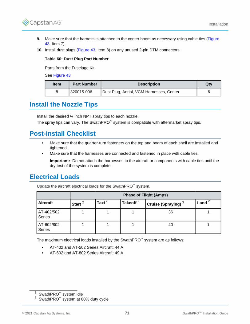
TM
Installation
9. Make sure that the harness is attached to the center boom as necessary using cable ties (Figure43, Item 7).
10. Install dust plugs (Figure 43, Item 8) on any unused 2-pin DTM connectors.
Table 60: Dust Plug Part Number
Parts from the Fuselage Kit
See Figure 43
Item Part Number Description Qty
8 320015-006 Dust Plug, Aerial, VCM Harnesses, Center 6
Install the Nozzle Tips
Install the desired ¼ inch NPT spray tips to each nozzle.
The spray tips can vary. The SwathPRO™ system is compatible with aftermarket spray tips.
Post-install Checklist• Make sure that the quarter-turn fasteners on the top and boom of each shell are installed and
tightened.• Make sure that the harnesses are connected and fastened in place with cable ties.
Important: Do not attach the harnesses to the aircraft or components with cable ties until thedry test of the system is complete.
Electrical LoadsUpdate the aircraft electrical loads for the SwathPRO™ system.
Phase of Flight (Amps)
Aircraft Start 2 Taxi 2 Takeoff 2 Cruise (Spraying) 3 Land 2
AT-402/502Series
1 1 1 36 1
AT-602/802Series
1 1 1 40 1
The maximum electrical loads installed by the SwathPRO™ system are as follows:
• AT-402 and AT-502 Series Aircraft: 44 A• AT-602 and AT-802 Series Aircraft: 49 A
2 SwathPRO™ system idle3 SwathPRO™ system at 80% duty cycle
© 2021 Capstan Ag Systems, Inc. 71 SwathPRO™ Installation Guide

TM
Installation
Weight and Balance InformationWeigh the modified aircraft and update the records.
Note: A calculated weight and balance is not acceptable to determine the updated weight andbalance of the modified aircraft.
Return to Service
1. Execute FAA Form 337 in accordance with 14 CFR Part 43, Appendix B.
2. Insert these into the maintenance records of the modified aircraft:
• Instructions for Continued Airworthiness• Copy of 337 and STC
3. Insert these into the Flight Manual for the Modified aircraft.
• Revised empty weight and corresponding CG determined in Section 16.2• Aircraft Flight Manual Supplement
4. Make an entry into the maintenance record of the modified aircraft in accordance with 14 CFR43.9.
© 2021 Capstan Ag Systems, Inc. 72 SwathPRO™ Installation Guide
TM
Setup
Section 4: Setup
Topics:
• CapView Button Descriptions• System Setup• Do the Factory Reset
Procedure• Location Setup Procedure• Upload a Profile and Set the
Preset Buttons• System Dry Tests• System Wet Test
© 2021 Capstan Ag Systems, Inc. 73 SwathPRO™ Installation Guide
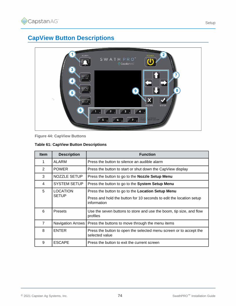
TM
Setup
CapView Button Descriptions
Figure 44: CapView Buttons
Table 61: CapView Button Descriptions
Item Description Function
1 ALARM Press the button to silence an audible alarm
2 POWER Press the button to start or shut down the CapView display
3 NOZZLE SETUP Press the button to go to the Nozzle Setup Menu
4 SYSTEM SETUP Press the button to go to the System Setup Menu
5 LOCATIONSETUP
Press the button to go to the Location Setup Menu
Press and hold the button for 10 seconds to edit the location setupinformation
6 Presets Use the seven buttons to store and use the boom, tip size, and flowprofiles
7 Navigation Arrows Press the buttons to move through the menu items
8 ENTER Press the button to open the selected menu screen or to accept theselected value
9 ESCAPE Press the button to exit the current screen
© 2021 Capstan Ag Systems, Inc. 74 SwathPRO™ Installation Guide
TM
Setup
System SetupThe system setup procedure includes:
1. Factory Reset
2. Location Setup Procedure
3. System Setup Procedure
4. Nozzle Setup Procedure
5. System Dry Test
6. System Wet Test
© 2021 Capstan Ag Systems, Inc. 75 SwathPRO™ Installation Guide
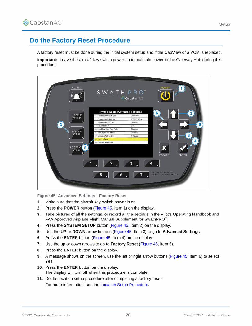
TM
Setup
Do the Factory Reset Procedure
A factory reset must be done during the initial system setup and if the CapView or a VCM is replaced.
Important: Leave the aircraft key switch power on to maintain power to the Gateway Hub during thisprocedure.
Figure 45: Advanced Settings—Factory Reset
1. Make sure that the aircraft key switch power is on.
2. Press the POWER button (Figure 45, Item 1) on the display.
3. Take pictures of all the settings, or record all the settings in the Pilot’s Operating Handbook andFAA Approved Airplane Flight Manual Supplement for SwathPRO™.
4. Press the SYSTEM SETUP button (Figure 45, Item 2) on the display.
5. Use the UP or DOWN arrow buttons (Figure 45, Item 3) to go to Advanced Settings.
6. Press the ENTER button (Figure 45, Item 4) on the display.
7. Use the up or down arrows to go to Factory Reset (Figure 45, Item 5).
8. Press the ENTER button on the display.
9. A message shows on the screen, use the left or right arrow buttons (Figure 45, Item 6) to selectYes.
10. Press the ENTER button on the display.The display will turn off when this procedure is complete.
11. Do the location setup procedure after completing a factory reset.
For more information, see the Location Setup Procedure.
© 2021 Capstan Ag Systems, Inc. 76 SwathPRO™ Installation Guide
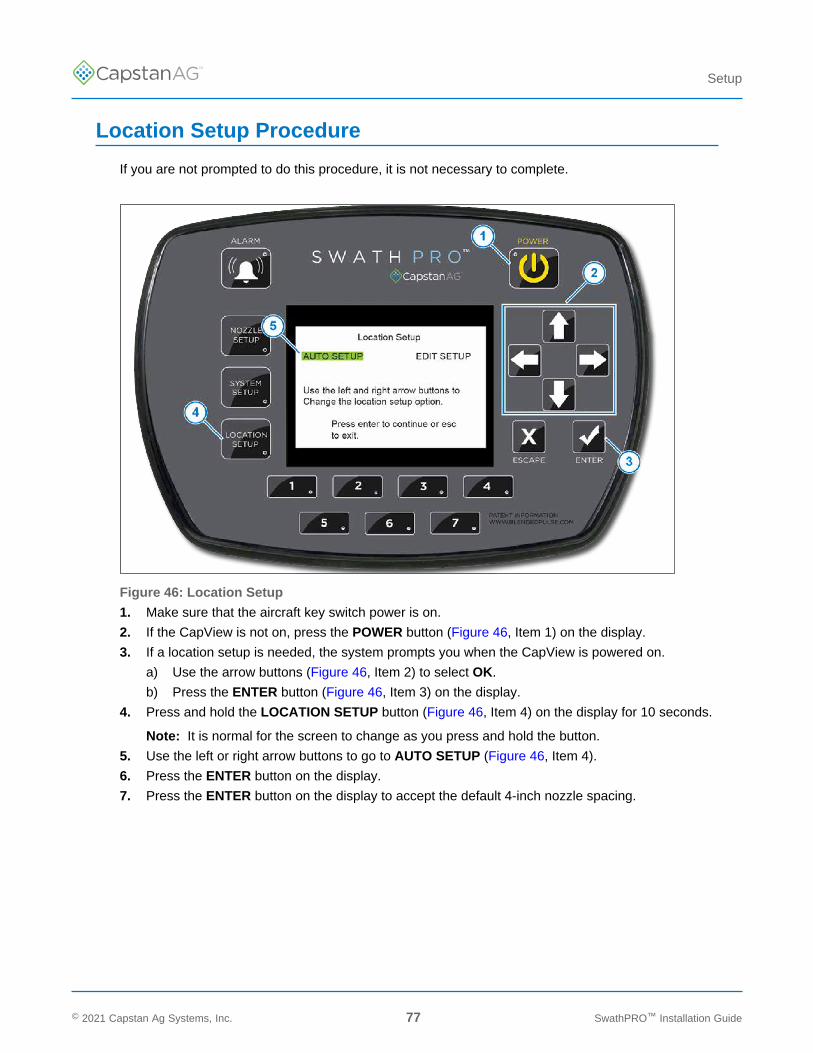
TM
Setup
Location Setup Procedure
If you are not prompted to do this procedure, it is not necessary to complete.
Figure 46: Location Setup
1. Make sure that the aircraft key switch power is on.
2. If the CapView is not on, press the POWER button (Figure 46, Item 1) on the display.
3. If a location setup is needed, the system prompts you when the CapView is powered on.
a) Use the arrow buttons (Figure 46, Item 2) to select OK.
b) Press the ENTER button (Figure 46, Item 3) on the display.
4. Press and hold the LOCATION SETUP button (Figure 46, Item 4) on the display for 10 seconds.
Note: It is normal for the screen to change as you press and hold the button.
5. Use the left or right arrow buttons to go to AUTO SETUP (Figure 46, Item 4).
6. Press the ENTER button on the display.
7. Press the ENTER button on the display to accept the default 4-inch nozzle spacing.
© 2021 Capstan Ag Systems, Inc. 77 SwathPRO™ Installation Guide

TM
Setup
Figure 47: Auto Location Setup
This screen shows a picture with the VCMs (Figure 47, Item 1) located on the booms.
The graphic along the bottom shows a VCM with a 15-nozzle wire harness (Figure 47, Item 2). Theblack dot (Figure 47, Item 3) represents the direction of the harness, and the nozzles are indicatedwith numbers. This graphic changes as you move the yellow highlighter from VCM to VCM. This canbe an indicator of which VCM is which, based on the number and location of the valves on the VCM.
Start with the VCM located on the far left section of the left boom.
8. Use the left or right arrow buttons (Figure 47, Item 4) to highlight the desired VCM.
9. Press the ENTER (Figure 47, Item 5) button on the display.
The highlight color will change to red and the nozzles on that VCM pulse.
10. Move the highlighted VCM using the left or right arrows to the physical location on the boom.
Example: Selected far left VCM (VCM #1), but it pulses at physical location #4.
11. Press the ENTER button on the display to stop the pulsing.
12. Press the up or down arrow buttons to flip the VCM graphic, so the VCMs on the left side mustshow the black dot on the left side. The VCMs on the right side must show the black dot on theright side.
13. Repeat the process from left to right until all of the VCMs are moved to their proper location andflipped to their proper orientation.
14. When finished, press the ESCAPE (Figure 47, Item 6) button three times.
This screen will give the option YES (to save) or NO (not to save) the entered data.
15. If the data is correct, use the right or left arrow buttons to go to YES.
16. Press the ENTER button.
A blue save bar will show and move across the screen. The CapView is saving all the data insidethe VCMs. This process may take a few minutes to complete.
Important: The CapView will shutdown to reboot shortly after selecting YES.
© 2021 Capstan Ag Systems, Inc. 78 SwathPRO™ Installation Guide
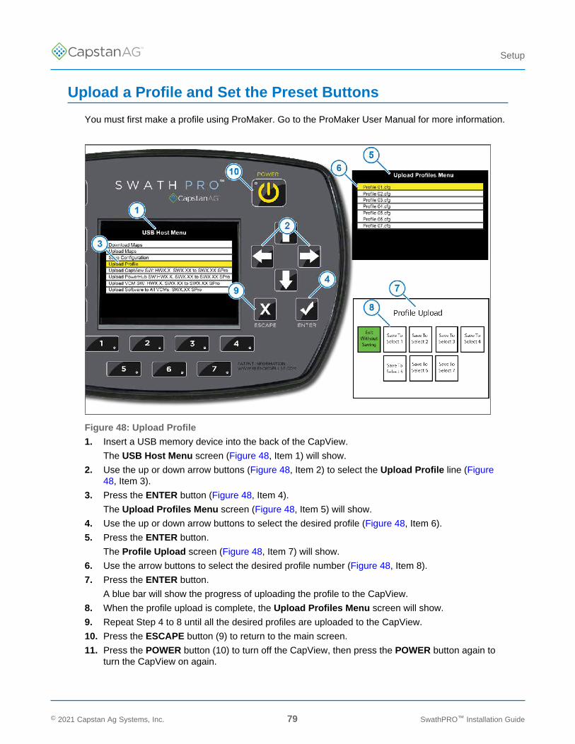
TM
Setup
Upload a Profile and Set the Preset Buttons
You must first make a profile using ProMaker. Go to the ProMaker User Manual for more information.
Figure 48: Upload Profile
1. Insert a USB memory device into the back of the CapView.
The USB Host Menu screen (Figure 48, Item 1) will show.
2. Use the up or down arrow buttons (Figure 48, Item 2) to select the Upload Profile line (Figure48, Item 3).
3. Press the ENTER button (Figure 48, Item 4).
The Upload Profiles Menu screen (Figure 48, Item 5) will show.
4. Use the up or down arrow buttons to select the desired profile (Figure 48, Item 6).
5. Press the ENTER button.
The Profile Upload screen (Figure 48, Item 7) will show.
6. Use the arrow buttons to select the desired profile number (Figure 48, Item 8).
7. Press the ENTER button.
A blue bar will show the progress of uploading the profile to the CapView.
8. When the profile upload is complete, the Upload Profiles Menu screen will show.
9. Repeat Step 4 to 8 until all the desired profiles are uploaded to the CapView.
10. Press the ESCAPE button (9) to return to the main screen.
11. Press the POWER button (10) to turn off the CapView, then press the POWER button again toturn the CapView on again.
© 2021 Capstan Ag Systems, Inc. 79 SwathPRO™ Installation Guide
TM
Setup
System Dry TestsDo these procedures to make sure that the nozzle valves are operating correctly:
• Boom Dry Test• Key Fob Boom Dry Test
Do the Boom Dry Test
1. Make sure that the engine is off and the aircraft key switch is on.
2. Make sure that the circuit breaker switch labeled SWATHPRO MAIN is on.
3. Turn on the CapView display.
4. If using the fan brake relay, put the fan brake switch in the SPRAY ON position.
5. Push the spray handle down.
All nozzle valves on the boom should start clicking.
6. Pull the spray handle up.
All nozzle valves should turn off and stop clicking.
© 2021 Capstan Ag Systems, Inc. 80 SwathPRO™ Installation Guide
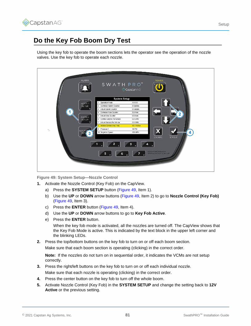
TM
Setup
Do the Key Fob Boom Dry Test
Using the key fob to operate the boom sections lets the operator see the operation of the nozzlevalves. Use the key fob to operate each nozzle.
Figure 49: System Setup—Nozzle Control
1. Activate the Nozzle Control (Key Fob) on the CapView.
a) Press the SYSTEM SETUP button (Figure 49, Item 1).
b) Use the UP or DOWN arrow buttons (Figure 49, Item 2) to go to Nozzle Control (Key Fob)(Figure 49, Item 3).
c) Press the ENTER button (Figure 49, Item 4).
d) Use the UP or DOWN arrow buttons to go to Key Fob Active.
e) Press the ENTER button.
When the key fob mode is activated, all the nozzles are turned off. The CapView shows thatthe Key Fob Mode is active. This is indicated by the text block in the upper left corner andthe blinking LEDs.
2. Press the top/bottom buttons on the key fob to turn on or off each boom section.
Make sure that each boom section is operating (clicking) in the correct order.
Note: If the nozzles do not turn on in sequential order, it indicates the VCMs are not setupcorrectly.
3. Press the right/left buttons on the key fob to turn on or off each individual nozzle.
Make sure that each nozzle is operating (clicking) in the correct order.
4. Press the center button on the key fob to turn off the whole boom.
5. Activate Nozzle Control (Key Fob) in the SYSTEM SETUP and change the setting back to 12VActive or the previous setting.
© 2021 Capstan Ag Systems, Inc. 81 SwathPRO™ Installation Guide

TM
Setup
System Wet TestDo this procedure to make sure that the nozzle valves are operating correctly.
Do the Key Fob Boom Wet Test
Using the key fob to operate the boom sections lets the operator see the operation of the nozzlevalves. Use the Key FOB to operate each nozzle.
The Key FOB works well when checking for plugged tips without wasting a significant amount ofproduct.
Figure 50: System Setup—Nozzle Control
1. Activate the Nozzle Control (Key Fob) on the CapView.
a) Press the SYSTEM SETUP button (Figure 50, Item 1).
b) Use the UP or DOWN arrow buttons (Figure 50, Item 2) to go to Nozzle Control (Key Fob)(Figure 50, Item 3).
c) Press the ENTER button (Figure 50, Item 4).
d) Use the UP or DOWN arrow buttons to go to Key Fob Active.
e) Press the ENTER button.
When the key fob mode is activated, all the nozzles are turned off. The CapView shows thatthe Key Fob Mode is active. This is indicated by the text block in the upper left corner andthe blinking LEDs.
© 2021 Capstan Ag Systems, Inc. 82 SwathPRO™ Installation Guide
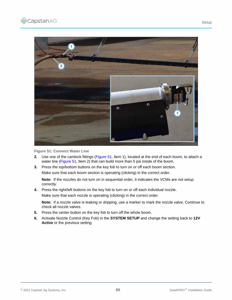
TM
Setup
Figure 51: Connect Water Line
2. Use one of the camlock fittings (Figure 51, Item 1), located at the end of each boom, to attach awater line (Figure 51, Item 2) that can build more than 5 psi inside of the boom.
3. Press the top/bottom buttons on the key fob to turn on or off each boom section.
Make sure that each boom section is operating (clicking) in the correct order.
Note: If the nozzles do not turn on in sequential order, it indicates the VCMs are not setupcorrectly.
4. Press the right/left buttons on the key fob to turn on or off each individual nozzle.
Make sure that each nozzle is operating (clicking) in the correct order.
Note: If a nozzle valve is leaking or dripping, use a marker to mark the nozzle valve. Continue tocheck all nozzle valves.
5. Press the center button on the key fob to turn off the whole boom.
6. Activate Nozzle Control (Key Fob) in the SYSTEM SETUP and change the setting back to 12VActive or the previous setting.
© 2021 Capstan Ag Systems, Inc. 83 SwathPRO™ Installation Guide

TM
Setup
© 2021 Capstan Ag Systems, Inc. 84 SwathPRO™ Installation Guide
This page intentionally left blank

TM
Index
Index
A
Applicable Aircraft Models 10
B
Before Installation 25Boom Dry Test 80Boom Shutoff Kit Schematic 56
C
CapViewInstallation 65
CapView Button Descriptions 74CapView Installation 65Change Log iiiChemical Safety 14Circuit Breaker Installation 44
D
Do the Factory Reset Procedure 76Do the Key Fob Boom Dry Test 81Do the Key Fob Boom Wet Test 82
E
Electrical Loads 71Emergency Safety 14External References vi
F
Factory Spray SystemRemoval 25
Fan Brake Relay Signal Harness Installation 62
G
Gateway Boom Extension Harness Installation 53Gateway Hub Identification 43Gateway Hub Installation
Back of the Luggage Compartment 39Inside the Luggage Compartment 40Underneath the Cockpit 42
Gateway Hub Mounting Location Options 38GPS Receiver Installation 64
I
Install Key Switch Power 48Install the Boom Hangers 26Install the Booms 26Install the Circuit Breakers and Power Harnesses 44Install the Fan Brake Relay Signal Harness 62Install the Flow Control Valve Harness 63Install the Gateway Boom Extension Harnesses 53Install the Gateway Hub Inside the LuggageCompartment 40Install the Gateway Hub On the Back of the LuggageCompartment 39Install the Gateway Hub Underneath the Cockpit 42Install the GPS Receiver 64Install the Maneuvering Speed Placard Decal 69Install the Nozzle Tips to the Booms 71Install the Parts to the Center Boom 69Install the Pressure Sensor 51Install the Servo Harness 63Install the Shutoff Kit 58Installation
CapView 65
K
Key Fob Boom Dry Test 81Key Fob Boom Wet Test 82Key Switch Power Installation 48
L
Location Setup Procedure 77
M
Maneuvering Speed Placard Installation 69
P
Parts List 19Personal Protective Equipment (PPE) 14Post-install Checklist 71Power Harnesses Installation 44PPE (Personal Protective Equipment) 14Prepare for Installation and Setup 16Preset Button Programming 79Pressure Sensor Installation 51Pressurized Fluid Lines 14Profile Upload 79
© 2021 Capstan Ag Systems, Inc. 85 SwathPRO™ Installation Guide

TM
Index
R
Remove the Factory Spray System 25Return to Service 72
S
Set the Preset Buttons 79Shutoff Kit Installation 58Signal Words 14Special Tools 11System Dry Test 80System Layout 17System Setup 75System Wet Test 82
T
This Manual 10
U
Upload a Profile 79
W
Weight and Balance Information 72
© 2021 Capstan Ag Systems, Inc. 86 SwathPRO™ Installation Guide

This page intentionally left blank

Application Systems for Professionals™CapstanAG.com | CapstanAG.ca
[email protected] | 855-628-7722
©2021 Capstan Ag Systems, Inc. All Rights Reserved. | All trademarks are owned by Capstan Ag Systems, Inc.This product may be covered by one or more U.S. Patents. For more information go to www.BlendedPulse.com
TM