Svenska Kraftnät’s requirements for documentation in cable ... · PDF...
34
UNIT, BUSINESS AREA OUR DESIGNATION AD, Plant documentation TR08-05 DATE CONSULTATION 2014-09-08 NT, NK, NL, AS, AFL, KI TECHNICAL GUIDELINES ISSUE APPROVED 3 Td Svenska Kraftnät’s requirements for documentation in cable projects - Applies for installation underground, underwater or in a tunnel This technical guideline defines Svenska Kraftnät’s requirements for documentation in power cable projects. The guideline is to be applied in both new construction projects and in reconstruction projects.
-
Upload
vuongkhanh -
Category
Documents
-
view
223 -
download
1
Transcript of Svenska Kraftnät’s requirements for documentation in cable ... · PDF...

UNIT, BUSINESS AREA OUR DESIGNATION AD, Plant documentation TR08-05
DATE CONSULTATION 2014-09-08 NT, NK, NL, AS,
AFL, KI TECHNICAL GUIDELINES
ISSUE APPROVED 3 Td
Svenska Kraftnät’s requirements for documentation in cable projects - Applies for installation underground, underwater or in a tunnel
This technical guideline defines Svenska Kraftnät’s requirements for documentation in power cable projects. The guideline is to be applied in both new construction projects and in reconstruction projects.

Updates Revision Change notification Date
1 First issue of the document 2011-07-04
2 Chapter 2.1 Project documentation has been issued and general clarification and grammatical adjustments have taken place.
2012-06-20
3 Parts of TR08-05:2 submarine cable and TR08-05:3 tunnel and bridge have been transferred to this TR. OF opto has been omitted and a new TR08-07 has been produced for fibre-optic cable. TR08-05:1 renamed TR08-05. The entire document has been updated throughout and partially reworked. Document lists for underground and submarine power cables as well as those laid in tunnels have been collected in the same document. (revised by Gunnar Gehlin, AFL)
2014-06-18

Contents
1 Introduction .............................................................................................................. 4
1.1 General ......................................................................................................... 4 1.2 Drawing requirements ................................................................................ 4 1.3 Sample drawings ......................................................................................... 4 1.4 File and folder name .................................................................................... 5
2 Document lists ........................................................................................................... 5
2.1 Division into document groups ................................................................... 5 2.1.1 Contents ......................................................................................... 5 2.1.2 Drawings ....................................................................................... 5 2.1.3 Situation documentation .............................................................. 5 2.1.4 Technical specifications ................................................................ 5 2.1.5 Earthing presentation................................................................... 6 2.1.6 Soil investigations/Bottom investigations .................................. 6 2.1.7 Calculations ................................................................................... 6 2.1.8 Measurements ............................................................................... 6 2.1.9 List of suppliers ............................................................................. 6 2.1.10 Technical quality documentation ................................................. 6 2.1.11 Technical descriptions .................................................................. 6 2.1.12 Material specifications ................................................................. 6 2.1.13 Photographs .................................................................................. 7 2.1.14 Maintenance document ................................................................ 7
2.2 Document list underground cable .............................................................. 7 2.3 Explanations for document list underground cable ................................ 12 2.4 Document list submarine cable ................................................................. 15 2.5 Explanations for document list submarine cable .................................... 19 2.6 Document list cable laid in tunnel ............................................................ 21 2.7 Explanations for document list cable laid in tunnel ................................ 25 Appendices – Sample drawings ........................................................................... 28

1 Introduction
1.1 General This technical guideline (TR08-05) itemises the documents, drawings and other
documents which are to be supplied to Svenska Kraftnät (Svk) in connection with
projects that involve new construction or reconstruction of power cable installations in
ground, water, tunnels or bridge structures.
The documentation according to this technical guideline shall include all plant
components and all equipment included in relevant cable projects. Project boundary to
adjacent projects is normally in terminal clamp for top bolt on the respective cable
termination. Racks for installation of cable terminations are normally included in the
cable project. Every cable project will be unique with respect to design and scope. The
requirements for documents according to document lists in this TR must therefore be
read as applicable where appropriate.
A cable project can be either a purely underground, submarine or tunnel cable project, or
a combination of them. In the latter case, the specific requirements for the
documentation for the respective part is derived from the appropriate section 2.2, 2.4 or
2.6 below.
1.2 Drawing requirements All drawings produced in the project with Svenska Kraftnät’s drawing number shall be
delivered in file format according to the document list further down in this TR.
Furthermore, all drawings for final documentation produced in the project shall also be
delivered in the file format ”Portable Document Format” (PDF).
All drawings are to be supplied in a scale suitable for the respective drawing, so that the
plant sections, components or equipment that the drawing presents are clearly set out
and the drawing is reasonably legible. Standard scales according to Svenska Kraftnät’s
technical guideline for drawings TR08-02 shall be used. An appropriate standard scale
shall be selected so that the plant sections, components or equipment that the drawing
presents are clear and legible. All drawings are to be of the ”As built” type.
All drawings described in this technical guideline where the file format is DWG, shall
have Svenska Kraftnät’s drawing frame and drawing number in accordance with TR08-
02. The requirements for some drawings are clarified in section 2.3 below.
1.3 Sample drawings To ensure that the drawings contain the information which Svenska Kraftnät intends, a
number of sample drawings have been produced. The sample drawings only show how
the documentation of the technical content should be configured, and not how actual
designs should be configured. Sample drawings are shown in appendices. For detailed
requirements for drawings see TR08-02.

1.4 File and folder name The document list in chapter 2 presents the documents which are to be delivered to
Svenska Kraftnät. The documents are to be delivered in a folder structure which
corresponds with the order in the document list. The table headings constitute folder
level 1, the section designations constitute folder level 2, and so on. The file names shall
comprise an informative text which makes it possible to determine the file’s contents
without the file having to be opened and read.
Below is an example of a limited part of the folder structure.
2 Document lists
2.1 Division into document groups The document lists below list the drawings and other documents which are to be
supplied as final technical documentation from the project. The following groups of
documents apply:
2.1.1 Contents Shall provide a summary of what is included in the technical documentation.
2.1.2 Drawings Drawings shall be supplied presenting the built plant’s design and construction both in
outline and in detail. The drawings can be general plans, detailed drawings, design
drawings or construction drawings. Drawings shall be dimensioned to the extent
required for the respective drawing’s interpretation and legibility. Construction drawings
shall be provided with bills of materials.
2.1.3 Situation documentation The aim of the situation documentation is to present the built plant’s geographic location
(coordinates) based on data entered. The situation documentation shall include both x/y
coordinates and z coordinate. TR08-06.
2.1.4 Technical specifications Document which shall present detailed technical data for plant section, apparatus,
component, equipment or similar supplied. The document is usually a data sheet, but
can also comprise an equivalent brief summary. The content can be electrical,
mechanical, thermal data/performance/requirement, material, dimensions, weights, etc.

2.1.5 Earthing presentation The document group shall show how the built cable installation's earthing system is
designed and constructed. This applies to both so-called "functional" and "protective"
earthing. Design and earth electrode resistances measured are to be presented. Svenska
Kraftnät’s earth electrode protocol shall be used and adjusted when necessary.
2.1.6 Soil investigations/Bottom investigations Shall present implementation and results of any soil investigations (cable underground
or in a tunnel) or bottom investigations (submarine cable). Can apply to, for example,
geotechnical investigations with the aim of examining the ground's character, soil type,
stability etc., thermal surveys, or investigations of underground water levels. For
submarine cables it entails documenting bottom conditions and finding a suitable route
etc.
2.1.7 Calculations Any electrical, thermal or mechanical calculations that the cable supplier or contractor in
the project has performed with the aim of ensuring the function and/or dimensioning a
part of the plant supplied are to be presented here.
2.1.8 Measurements This document group comprises the results from the measurements performed within
the framework of the project. It might involve measurements of thermal resistivity in the
ground, measurements of earth electrode resistance or something else. The results from
the impedance measurement of the cable system which take place after completion shall
also be presented here. However, measurements that are included in the supplier’s final
testing after installation are not referred to under this heading, Site Acceptance Test
(SAT).
2.1.9 List of suppliers Information about suppliers of different materials and equipment is presented here. It
might involve material included in the cable system per se, but also material in contracts.
2.1.10 Technical quality documentation Records of tests performed according to relevant standards are presented here. This
concerns both qualification tests (Type Test) and tests during manufacturing/production
(Factory Acceptance Test, FAT) and tests after installation (Site Acceptance Test, SAT).
Inspection records and similar from surveys and inspections during the course of the
project are also presented here.
2.1.11 Technical descriptions Documents produced which have the aim of providing a technical account of the cable
system, and/or parts of it. The documents can also provide a technical description of
assembly, laying or installation of the plant or parts of it.
2.1.12 Material specifications Documents that present composition/content of certain materials used in cable systems,
components, equipment, filling material or similar. It might involve environmentally-

related declarations, or quality/performance-related declarations (e.g. the composition
of thermal protective filling).
2.1.13 Photographs Photographs are primarily to be used to document plant sections which are not normally
visible, but which for various reasons it is beneficial to show in a photograph, e.g.
equipment for and design of joint locations in the ground. Photographs can also be used
to advantage to document elements in the production process, or to document tests and
checks performed on equipment delivered.
2.1.14 Maintenance document Examples of what is presented here are the supplier’s method descriptions for cable
splicing and assembly of cable terminations, recommendations for maintenance and
service of equipment delivered, as well as recommendations for storage of spare parts.
2.2 Document list underground cable In this technical guideline, underground power cable refers to power cable that is
designed to be laid on land, and which is either laid directly in the ground (excavated or
blasted cable trench), in a pipe in a cable trench, in a concrete-encased pipe or
equivalent, in a culvert at ground level, or through laying without excavating, e.g. guided
drilling.
In exceptional cases, cable designed to be laid on land (provided that it is equipped with
secure radial water barriers), may be laid in shallow lakes or equivalent. Such laying is
also included in this document list.
MK Underground cable Description
File type Document/Item
MK00 Contents MK00.01 Document list Complete list of all documents and other items included in
the documentation. Document name, revision number, issue/revision date shall be shown.
xls/xlsx
MK01 Drawings MK01.01 Drawing list Complete list of drawings. Drawing number shall be
indicated. Drawings shall be furnished with Svk drawing number
xls/xlsx
MK01.02 List of cancelled drawings in the Bank
xls/xlsx
MK01.03 General plan cable route The drawing shall present an overview of the cable’s route and geographic location. See in addition description under section 2.3.
DWG + PDF_A
MK01.04 Plan drawing & Profile drawing The drawing shall present the power cables surveyed in plan and profile. Height scale shall be shown. Any marking poles shall be set out with surveyed positions.
DWG + PDF_A
MK01.05 General plan station installation The drawing shall show location of cable terminations within station area. The drawing (which can be a site plan of the station) shall show other vital parts of the station. Wiring connected to the power cables shall be shown.
DWG + PDF_A

MK Underground cable Description
File type Document/Item
MK01.06 General plan joint location The drawing shall present the joint location’s design and arrangement. Joint locations with different designs are to be presented in separate drawings. See in addition under section 2.3.
DWG + PDF_A
MK01.07 Detailed drawings/Cross sections with normal underground cables (Direct Buried).
Where applicable, the drawings shall show trench sections, i.e. cross sections of the cables’ positions in the cable trench. See in addition under section 2.3.
DWG + PDF_A
MK01.08 Detailed drawings/Cross sections when laying piping.
Where applicable, the drawings shall show cross sections of piping. See in addition description under section 2.3.
DWG + PDF_A
MK01.09 Detailed drawings/Cross sections when laying culverts.
Where applicable, the drawings shall show cross sections of the cable installation when laying culverts. See in addition description under section 2.3.
DWG + PDF_A
MK01.10 Detailed drawings/Cross sections when intersecting other infrastructure
The drawings shall show relevant cross sections of the cable installation at crossing point with other infrastructure, such as other mains or roads/railway etc. See in addition description under section 2.3.
DWG + PDF_A
MK01.11 Assembly drawing of cable termination
The drawing shall show the cable termination fitted on its rack, as well as cable current transformers, junction boxes, PD-measuring boxes etc. and wiring and earthings. Location of PD-sensors shall be set out.
DWG + PDF_A
MK01.12 Detailed drawing of joint location The detailed drawing shall present the joint location’s complete design in more detail than the general plan. See in addition under section 2.3.
DWG + PDF_A
MK01.13 Design drawings concrete Drawings which show design of any base plates for joint location, or design of any concrete enclosures for junction boxes or similar.
DWG + PDF_A
MK01.14 Design drawings steel Design drawings for racks for cable terminations shall be presented, as well as design drawings for any assembly components for junction boxes etc. If adapters or similar are required for assembly of cable terminations on racks, design drawings for these shall also be presented.
DWG + PDF_A
MK01.15 Detailed drawings cable joints This refers to the supplier’s/manufacturer’s detailed drawing of the cable joint’s construction.
DWG + PDF_A
MK01.16 Detailed drawings cable termination This refers to the supplier’s/manufacturer’s detailed drawing of the cable termination’s construction.
DWG + PDF_A
MK01.17 Detailed drawings cable clamps This refers to the supplier’s/manufacturer’s detailed drawing of the design of cable clamps’ supplied. (Cable clamps are used for cable terminations and if necessary for securing joint location.)
DWG + PDF_A
MK01.18 Detailed drawings junction boxes etc.
This refers to the supplier’s/manufacturer’s detailed drawings of junction boxes/link boxes or measuring boxes supplied.
DWG + PDF_A
MK01.19 Phase sequence diagram See description under section 2.3. PDF_A MK01.20 Earthing diagram See description under section 2.3. PDF_A
MK02 Situation documentation MK02.01 Coordinate lists and files The entire cable installation including vital parts such as
joint locations, concrete enclosures, connection chambers, fibre-optic chambers, pipe laying etc. shall be surveyed and presented according to Svk’s instructions, see TR08-06.
See TR08-
06
MK03 Technical specifications MK03.01 Technical specification power cable This refers to the supplier’s technical specification
(Design Report), partly in words, of design/construction of the cable, as well as data sheets which present electrical, thermal and mechanical data, as well as information about dimensions and weight and handling the cable.
PDF_A
MK03.02 Technical specification cable joints This refers to the supplier’s technical specification in words of the design of the cable joint supplied, as well as data sheets which present electrical, thermal and mechanical data, as well as information about dimensions and weight for complete joint housings.
PDF_A

MK Underground cable Description
File type Document/Item
MK03.03 Technical specification cable termination
This refers to the supplier’s technical specification in words of the design of the cable termination supplied, as well as data sheets which present electrical, thermal and mechanical data, as well as information about dimensions and weight for complete cable termination.
PDF_A
MK03.04 Technical specification ducting pipe The supplier’s data sheet and drawings for product supplied.
PDF_A
MK03.05 Technical specification cable current transformers
The supplier's data sheet and drawings for component supplied
PDF_A
MK03.06 Technical specification fibre-optic cables
The supplier’s data sheet/technical specification for fibre-optic cables supplied for communication or DTS
PDF_A
MK03.07 Technical specification junction boxes and earthing boxes
The supplier’s data sheet/technical specification for component supplied
PDF_A
MK03.08 Technical specification cable ties, stripes or means of attachment for cable
The supplier’s data sheet/technical specification for component supplied. Here, means of attachment refers to any cable clamps or equivalent at joint locations.
PDF_A
MK03.09 Technical specification fibre-optic chambers or any other chambers
The supplier’s data sheet/technical specification for chambers supplied
PDF_A
MK03.10 Technical specification hoses/pipes for communication cables
The supplier’s data sheet/technical specification for pipes and/or hoses supplied
PDF_A
MK03.11 Technical specification equipment for temperature monitoring (DTS)
The supplier’s data sheet/technical specification for system solution supplied. The system’s performance shall be specified. Shall be supplemented with a technical description.
PDF_A
MK03.12 Technical specification equipment for PD-measurement
The supplier’s data sheet/technical specification for solution supplied. Measurement performance etc. shall be specified. Shall be supplemented with a technical description
PDF_A
MK03.13 Technical specification and marking of pipe system in electric power installations
Cable marking poles. AMA EL. YTB.1632 Shall be entered with coordinates in Sweref99 TM
PDF_A
MK04 Earthing presentation MK04.01 Earthing description A comprehensive description of the earthing system’s
design. The description shall be sufficiently detailed to enable understanding of the technical construction. Integral components/equipment shall be specified.
PDF_A
MK04.02 Earthing map Planimetric map in scale 1:2,000 of cable installation, earth wires and earth electrodes drawn in.
DWG + PDF_A
MK04.03 Measuring protocol for step and touch voltages
If this is required: Protocol which shows results of measurements performed of step and touch voltages incl. mapping of low voltage network
PDF_A
MK05 Soil investigations MK05.01 Soil investigation records Results of soil investigations performed are to be
presented. Relevant investigations are mapping of soil types, stability assessments, surveys of ground resistivity etc. Exploratory drilling is also accommodated under this heading. Where cables are laid in shallow lakes and similar, results from bottom surveys can also be included.
PDF_A
MK06 Calculations MK06.01 Capacity calculations The supplier’s calculation results for the expected thermal
fan out for cable systems supplied, under given/assumed conditions. Likewise, results from calculation of the cable system’s short-circuit resistance shall be presented.
PDF_A
MK06.02 Mechanical calculations Any mechanical calculations performed within the framework of the project shall be presented here. For example, it might involve calculations due to modifications or additions to original designs.
PDF_A
MK06.03 Geotechnical calculations Any geotechnical calculations performed within the framework of the project shall be presented here. For example, it might involve stability calculations to ensure carrying capacity.
PDF_A
MK07 Measurements (not included in testing)

MK Underground cable Description
File type Document/Item
MK07.01 Measuring protocol ground resistivity
Provided that such measurements are performed, results of measurements of the ground’s thermal resistivity in [K•m/W] before excavating the cable trench are to be presented here
xls/xlsx, PDF_A
MK07.02 Measuring protocol compaction control
The results of measurements taken of degree of compaction in cable foundation and protective filling (Troxler measurement or equivalent method) are to be presented here.
xls/xlsx, PDF_A
MK07.03 Measuring protocol sheath test after cable laying
The results from sheath tests performed in connection with laying power cables (not to be confused with sheath test included in SAT) are to be presented here.
xls/xlsx, PDF_A
MK07.04 Measuring protocol impedance measurement
The results of measurements taken of cable joint’s plus-, minus- and zero-sequence impedances after completion, but before commissioning, shall be presented here. To be performed by cable supplier or another party.
xls/xlsx, PDF_A
MK07.05 Measuring protocol earth electrode measurements
In accordance with Svenska Kraftnät Excel template (modified for cable project).
xls/xlsx
MK08 List of suppliers MK08.01 List of materials suppliers A list of qualified suppliers of critical materials, such as
insulating oil, PEX-material, compound material joints etc. xls/xlsx, PDF_A
MK08.02 List of equipment suppliers A list of suppliers of accessories/equipment, such as SVLs, DTS systems etc.
xls/xlsx, PDF_A
MK09 Technical quality documentation
MK09.01 Inspection record Records from surveys and inspections performed are to be presented here. Relevant inspections are checking cable trench, conduit foundation, protective filling, checking after laying cable, backfilling, assembly work, as well as Final inspection, Operational inspection, Guarantee inspection.
xls/xlsx, PDF_A
MK09.02 Measuring protocol thermal protective filling
The supplier’s records showing that the thermal sand supplied meets the set requirements are to be presented here.
PDF_A
MK09.03 Measuring protocol bentonite filling The supplier’s records showing that the thermal filling supplied (bentonite) meets the requirements are to be presented here.
PDF_A
MK09.04 Records Type Test Records of tests the supplier has performed on cable and all accessories included (cable joints and cable terminations). Type test of complete cable systems shall be presented. Type testing of junction boxes shall also be presented. The type test shall be performed according to applicable IEC standards. Tests for HVDC cables shall be performed according to Cigré TB 496
PDF_A
MK09.05 Records of Sample Test Records of sample tests performed by the supplier. According to applicable IEC standard. Tests for HVDC cables shall be performed according to Cigré TB 496
PDF_A
MK09.06 Routine test Records of routine tests performed by the supplier. According to applicable IEC standard. Tests for HVDC cables shall be performed according to Cigré TB 496
PDF_A
After Installation Tests MK09.07 Records of Sheath Tests (included
in SAT) Records of sheath tests (DC) of complete cable systems the supplier has performed, as well as cross-connection systems where applicable. According to IEC
PDF_A
MK09.08 Records of Phase Sequence Tests Records of phase sequence tests the supplier has performed. According to customary standards.
PDF_A
MK09.09 Records of PD measurement Test records from PD measurements on all accessories fitted with PD sensors. If PD sensors are installed and performed according to the supplier’s standard.
PDF_A
MK09.10 Records Impedance measurement Test records from measurements performed by the supplier of plus-, minus- and zero-sequence impedance data.
PDF_A
MK09.11 Records of AC or DC test (Operational test)
Records of AC tests performed by the supplier. The test is to be performed according to applicable IEC standards and/or according to agreement.
PDF_A

MK Underground cable Description
File type Document/Item
MK09.12 Records TDR (Time Domain Reflectometry)
Where appropriate: Records of TDR measurements performed by the supplier.
PDF_A
MK09.13 ITP (inspection and test plan) Information test and quality control shall be implemented
PDF_A
MK09.14 NCR (non conformance report) Deviation reports, ISO9001 PDF_A
MK10 Technical descriptions MK10.01 Technical description cable
systems The supplier’s overall technical description of cable systems installed. The description shall present the system’s fundamental structure and function, including main integral components and screen connection.
PDF_A
MK10.02 Technical description cable installation
Description of cable installation’s construction, based on AMA
xls/xlsx, PDF_A
MK10.03 Technical description DTS system The supplier’s overall description of structure and function of system supplied for measurement of the cable temperature, DTS system (if installed). The description shall set out functional principle, as well as how and where measurement/monitoring takes place, installation of measurement fibre etc.
PDF_A
MK11 Material specifications MK11.01 Material specification protective
filling The supplier’s data sheet/technical specification for thermal material supplied. Screening curve shall be presented.
PDF_A
MK11.02 Material specification filling material for pipe laying
The supplier’s data sheet for bentonite mixture or equivalent supplied
PDF_A
MK11.03 List of materials (MSDS) The supplier’s summary of content declarations for relevant material included in cable and accessories. Primarily applies to insulating oils, any compound materials, plastics.
PDF_A
MK12 Photographs MK12.01 Photographic documentation of joint
locations The photographs shall document all joint locations. The photographs shall be taken when the joint location is fully completed technically, but before protective filling/backfilling has been implemented. A sketch with a north arrow to show where north is, is to be placed in the trench when photographing the joints in the trench.
JPEG
MK13 Maintenance document MK13.01 Maintenance manual Cable system The supplier’s specific advice and instructions for
operation and maintenance of cable system supplied.
PDF_A
MK13.02 Instructions cable laying The supplier’s specific advice and instructions for cable laying and handling of power cable supplied.
PDF_A
MK13.03 Method description cable splicing The supplier’s description as a basis for correct assembly of cable joints (spare parts) supplied
PDF_A
MK13.04 Method description Assembly of cable terminations
The supplier’s description as a basis for correct assembly of cable terminations (spare parts) supplied.
PDF_A
MK13.05 Repair agreement Cable splicing A repair agreement shall be signed with the cable supplier to ensure rapid access to repair staff and resources in the event of a cable fault.
PDF_A
MK13.06 List of spares The supplier shall compile a list of all spare parts (cable, joints, end parts etc.) which have been supplied. The document shall also include instructions for storage and handling of the spare parts, as well as information about the predicted useful service life.
PDF_A
MK13.07 Operation and Maintenance Instruction for DTS system
Where appropriate: The supplier’s specific advice and instructions for operation and maintenance of DTS equipment supplied. The instruction shall include operation of the system.
PDF_A
MK13.08 Traceability documentation Protocol presenting which cable lengths (unique number) are installed where, ID no. of all joints, cable terminations, etc. installed shall be set out.
PDF_A

2.3 Explanations for document list underground cable Explanations and clarifications of certain of the points in the document list according to
the above are provided below.
MK01.03 General plan cable route A general plan shall function as an overall document which clearly shows the cable
installation's route. The general plan shall refer to underlying drawings. The type and
number of the various underlying drawings shall be clearly set out on the general plan.
The general plan shall be according to scale and drawn up in such a way as to clearly set
out the cable connection’s geographic location. Roads, buildings etc. in the vicinity of the
cable route shall be shown. Any pipe installations, intersections with other mains
structures and similar shall be marked on the drawing. If legibility requires it, the
general plan shall be divided into a number of drawings. For example, see appendix 1.
MK01.06 General plan joint location The drawing shall present the joint location’s design and arrangement. The locations of
the joint housings shall be set out, as well as other equipment such as junction boxes,
boxes for PD measurement etc. Any concrete enclosures or chambers for these boxes
shall also be shown. If a concrete slab or equivalent has been placed in the jointing pit,
this shall be shown.
MK01.07 Cross sections with normal cable laying in the ground Sectional drawings which show the cable trench’s dimensions and the power cables’
positions in the cable trench shall be produced for the different installation
configurations that occur along the cable route. Sectional drawing with direct burial in
the ground shall as a minimum show:
• Trench depth
• Trench bottom width
• Dimensions of protective filling (cable sand or equivalent)
• Depth of filling above the cables
• The power cables’ positions, with reciprocal distance between cables.
• Location of cable protection and warning mesh or equivalent
• Type of backfill/cable sand
• Type of surrounding ground (moraine, earth, clay, etc.)
• Any surface layer over the cable installation
• Location of earth wires.
• Location of any fibre-optic cables/empty pipes for communication
• Location of any fibre-optic cables for temperature measurement (DTS)
• Other mains structures (electricity, sewage, water, district heating, telecoms,
fibre-optic) parallel to the cable installation which are located at a distance of ≤ 5
m from outer cable.
Each sectional drawing shall be marked with coordinates (starting point) according to
Svenska Kraftnät’s technical guideline for surveying, TR08-06, and shall also be given an
ID-number. Coordinates shall agree with coordinates entered for the cable installation.
The sectional drawing’s starting point and ID shall be set out in the general plan. Each
sectional drawing shall apply until reference to another sectional drawing is made.
Direction in relation to the next sectional drawing that applies is governed by the
surveying.

Breakpoint for production of new sectional drawing is when there is a significant change
in the particular cross section. Examples of significant changes are when trench depth
and/or filler depth changes by more than 20 cm, if the power cables’ (or groups of
cables) reciprocal distance changes by more than 10 cm, if protective filling or
surrounding soil type changes, or if a change occurs in the location of cable
protection/warning mesh. There is also a breakpoint if a change occurs in the
installation of earth wires or fibre-optic/telecoms lines, or in a jointing chamber. For
example, see appendix 3.
Sectional drawings for joint locations and intersections with another infrastructure are
dealt with separately.
MK01.08 Cross sections for pipe laying Pipe laying here refers to all pipe laying, i.e. ”normal” pipe laying in an excavated cable
trench, pipe laying after guided drilling, hammer drilling or similar, or e.g. ducting pipe
embedded in concrete or similar. In this context, pipe laying also includes crossing water
courses or other catchment areas, where the installation cannot be regarded as
submarine cables. Sectional drawing for pipe laying shall as a minimum show:
• Installation depth
• The pipes’ positions, with reciprocal distance between them.
• Pipe diameter and pipe thickness
• Pipe material and pipe filling (material)
• Location of any cable cover and warning mesh or equivalent
• Type of backfill/cable sand and/or type of surrounding soil
• Any surface layer over the cable installation
• Any reinforced cable protection, for example concrete slabs or similar.
• Location of earth wires.
• Location of any fibre-optic cables/empty pipes for communication
• Location of any fibre-optic cables for temperature measurement (DTS)
• Other mains structures (electricity, sewage, water, district heating, telecoms,
fibre-optic) parallel to the cable installation which are located at a distance of ≤ 5
m from outer cable.
Each sectional drawing shall be marked with coordinates according to the same principle
described under MK01-07 above. Breakpoint for production of new sectional drawing is
the same as for normal laying in the ground, when significant changes occur in
applicable cross sections. With, for example, guided drilling with a substantial
installation depth and a substantial distance between pipe/cables, there is less sensitivity
for deviations and assessment of significant changes may therefore be made from case to
case here. For example, see appendix 2.
MK01.09 Cross sections with culvert laying Culvert laying refers here to all cable laying in closed or open (with cover or grate)
culverts/trough of concrete or equivalent, located at ground level. Sectional drawing for
pipe laying shall as a minimum show:
• Trench depth for the culvert
• The culverts/trough’s dimensions (width and height)
• Material thickness and material in the construction
• The power cables’ positions with reciprocal distance
• Any occurrence of filling material and/or cable sand

• Any spacers, brackets or cable clamps etc.
• Location of earth wires.
• Location of any fibre-optic cables/empty pipes for communication
• Location of any fibre-optic cables for temperature measurement (DTS)
• Other mains structures (electricity, sewage, water, district heating, telecoms,
fibre-optic) parallel to the cable installation which are located at a distance of ≤ 2
m from outer cable.
Each sectional drawing shall be marked with coordinates according to the same principle
described under MK01-07 above. Breakpoint for production of new sectional drawing is
the same as for normal laying in the ground, when significant changes occur in
applicable cross sections. For culvert laying a change in the culvert’s dimensions of more
than 20 cm is counted as significant.
MK01.10 Cross sections when intersecting with other infrastructure Specific sectional drawings shall be produced at points where the cable installation
intersects with another infrastructure. Infrastructure here refers to roads, railways etc.,
as well as other mains structure (electricity, telecoms, fibre-optic, water, sewage, district
heating etc.). In addition to the specifications under MK01.07, MK01.08 or MK01.09
above, sectional drawings for intersections with other infrastructure shall as a minimum
also show:
• Positioning/location for intersecting infrastructure
• Distance between power cables and intersecting infrastructure
• With roads/railway: Dimensions of and material in roadbed resp. embankment
and its substructure. Any protective or strengthening measures.
• With mains structure: Type of mains, mains dimension and material. Where
appropriate, voltage level. Number of intersecting mains (if more than one).
Each sectional drawing shall be marked with coordinates according to the same principle
described under MK01-07 above.
MK01.12 Detailed drawing joint location In addition to what is stipulated for general plan according to MK01.06, the detailed
drawing shall also present the power cables’ locations, any cross-connection cables,
earthing cables, measurement cables, as well as earth wires/counterpoise wires. Location
of any PD sensors shall be shown. Individual cables shall be ID marked.
MK01.19 Phase sequence diagram A phase sequence diagram shall be presented, where the location of phases L1, L2 and L3
is clearly set out along the entire cable route from station to station, through any pipe
ducting and past joint locations. Any transposition points shall be clearly shown, and the
phases’ location before and after such transposition points shall be presented. Linear
measurement in m at each transposition point shall be given. The phases’ positions
within the respective cable group shall be shown in the cross section. For example, see
appendix 4.
MK01.20 Earthing diagram A diagram of the cable system's earthing system shall be produced. The diagram shall
present earth wires/counterpoise wires, earth electrode, as well as the cable shields'
connections in all relevant connecting points such as station connections, jointing points
and earthing points. Dimensions of earthing cables shall be specified. Earthing points
shall be drawn in and lengths in m to earthing points shall be indicated. Any cross-
connection boxes and/or earthing boxes shall be drawn in and the cable shields’
connections and interconnections in them shall be clearly set out. For example, see
appendix 5.
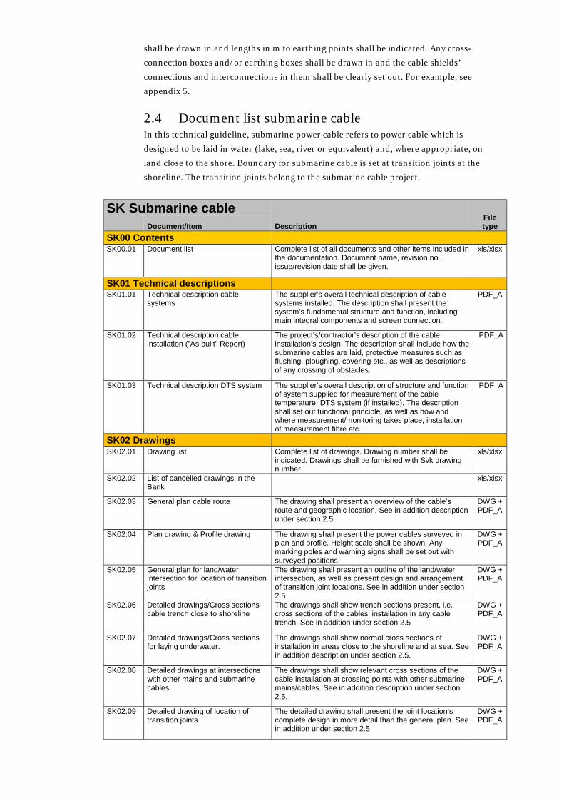
2.4 Document list submarine cable In this technical guideline, submarine power cable refers to power cable which is
designed to be laid in water (lake, sea, river or equivalent) and, where appropriate, on
land close to the shore. Boundary for submarine cable is set at transition joints at the
shoreline. The transition joints belong to the submarine cable project.
SK Submarine cable Description
File type Document/Item
SK00 Contents SK00.01 Document list Complete list of all documents and other items included in
the documentation. Document name, revision no., issue/revision date shall be given.
xls/xlsx
SK01 Technical descriptions SK01.01 Technical description cable
systems The supplier’s overall technical description of cable systems installed. The description shall present the system’s fundamental structure and function, including main integral components and screen connection.
PDF_A
SK01.02 Technical description cable installation (”As built” Report)
The project’s/contractor’s description of the cable installation’s design. The description shall include how the submarine cables are laid, protective measures such as flushing, ploughing, covering etc., as well as descriptions of any crossing of obstacles.
PDF_A
SK01.03 Technical description DTS system The supplier’s overall description of structure and function of system supplied for measurement of the cable temperature, DTS system (if installed). The description shall set out functional principle, as well as how and where measurement/monitoring takes place, installation of measurement fibre etc.
PDF_A
SK02 Drawings SK02.01 Drawing list Complete list of drawings. Drawing number shall be
indicated. Drawings shall be furnished with Svk drawing number
xls/xlsx
SK02.02 List of cancelled drawings in the Bank
xls/xlsx
SK02.03 General plan cable route The drawing shall present an overview of the cable’s route and geographic location. See in addition description under section 2.5.
DWG + PDF_A
SK02.04 Plan drawing & Profile drawing The drawing shall present the power cables surveyed in plan and profile. Height scale shall be shown. Any marking poles and warning signs shall be set out with surveyed positions.
DWG + PDF_A
SK02.05 General plan for land/water intersection for location of transition joints
The drawing shall present an outline of the land/water intersection, as well as present design and arrangement of transition joint locations. See in addition under section 2.5
DWG + PDF_A
SK02.06 Detailed drawings/Cross sections cable trench close to shoreline
The drawings shall show trench sections present, i.e. cross sections of the cables’ installation in any cable trench. See in addition under section 2.5
DWG + PDF_A
SK02.07 Detailed drawings/Cross sections for laying underwater.
The drawings shall show normal cross sections of installation in areas close to the shoreline and at sea. See in addition description under section 2.5.
DWG + PDF_A
SK02.08 Detailed drawings at intersections with other mains and submarine cables
The drawings shall show relevant cross sections of the cable installation at crossing points with other submarine mains/cables. See in addition description under section 2.5.
DWG + PDF_A
SK02.09 Detailed drawing of location of transition joints
The detailed drawing shall present the joint location’s complete design in more detail than the general plan. See in addition under section 2.5
DWG + PDF_A

SK Submarine cable Description
File type Document/Item
SK02.10 Design drawings concrete Drawings which show design of any base plates at joint location, design of any concrete enclosures for junction boxes or concrete construction for ”Hang-off”.
DWG + PDF_A
SK02.11 Detailed drawings cable joints This refers to the supplier’s/manufacturer’s detailed drawing of structure of transition joints and any submarine joints.
DWG + PDF_A
SK02.12 Detailed drawings cable clamps This refers, where applicable, to the supplier’s//manufacturer’s detailed drawing of design of cable clamps supplied (can be used at transition joints).
DWG + PDF_A
SK02.13 Detailed drawings junction boxes etc.
This refers to the supplier’s/manufacturer’s detailed drawings of junction boxes/link boxes or measuring boxes supplied.
DWG + PDF_A
SK02.14 Phase sequence diagram See description under section 2.5. PDF_A SK02.15 Earthing diagram See description under section 2.5. PDF_A
SK03 Situation documentation SK03.01 Coordinate lists and files The entire cable installation including vital parts such as
joint locations, concrete enclosures, connection chambers, fibre-optic chambers, pipe laying etc. shall be surveyed and presented according to Svk’s instructions, see TR08-06.
See TR08-
06
SK04 Technical specifications SK04.01 Technical specification power cable This refers to the supplier’s technical specification
(Design Report), partly in words, of design/construction of the cable, as well as data sheets which present electrical, thermal and mechanical data, as well as information about dimensions and weight and handling the cable.
PDF_A
SK04.02 Technical specification cable joints This refers to the supplier’s technical specification, partially in words, of the design of the cable joint supplied, data sheets which present electrical, thermal and mechanical data, as well as information about dimensions and weight for complete joint housing. Applies to both transition joints and submarine joints.
PDF_A
SK04.03 Technical specification cable termination
The supplier's data sheet and drawings for component supplied.
PDF_A
SK04.04 Technical specification ducting pipe The supplier’s data sheet and drawings for product supplied. (Where appropriate).
PDF_A
SK04.05 Technical specification hoses/pipes for communication cables
The supplier’s data sheet/technical specification for pipes and/or hoses supplied
PDF_A
SK04.06 Technical specification fibre-optic chambers or any other chambers
The supplier’s data sheet/technical specification for chambers supplied
PDF_A
SK04.07 Technical specification fibre-optic cables
The supplier’s data sheet/technical specification for fibre-optic cables supplied for communication or DTS
PDF_A
SK04.08 Technical specification cable current transformers
The supplier's data sheet and drawings for component supplied. (Where appropriate)
PDF_A
SK04.09 Technical specification junction boxes and earthing boxes
The supplier’s data sheet/technical specification for component supplied
PDF_A
SK04.10 Technical specification cable ties, stripes or means of attachment for cable
The supplier’s data sheet/technical specification for product supplied. Here, means of attachment refers to any cable clamps or equivalent at joint locations.
PDF_A
SK04.11 Technical specification equipment for temperature monitoring (DTS)
The supplier’s data sheet/technical specification for system solution supplied. The system’s performance shall be specified. Shall be supplemented with a technical description.
PDF_A
SK04.12 Technical specification equipment for PD-measurement
The supplier’s data sheet/technical specification for solution supplied. Measurement performance etc. shall be specified. Shall be supplemented with a technical description
PDF_A
SK04.13 Technical specifications equipment for laying submarine cable
The contractor’s/supplier’s technical specifications for cable laying vessel and other laying equipment such as ROVs, flushing equipment, ploughing equipment etc.
PDF_A
SK04.14 Technical specification equipment for locating faults
The supplier’s data sheet/technical specification for equipment supplied. Measurement performance etc. shall be specified. Shall be supplemented with a technical description
PDF_A
SK05 Material specifications

SK Submarine cable Description
File type Document/Item
SK05.01 Material specification protective filling
The supplier’s data sheet/technical specification for thermal material supplied. Screening curve shall be presented.
PDF_A
SK05.02 Material specification filling material for pipe laying etc.
The supplier’s data sheet for bentonite mixture or equivalent supplied
PDF_A
SK05.03 List of materials (MSDS) The supplier’s summary of content declarations for relevant material included in cable and accessories. Primarily applies to insulating oils, any compound materials, plastics.
PDF_A
SK06 List of suppliers SK06.01 List of materials suppliers A list of qualified suppliers of critical material, such as
insulating oil, PEX-material, compound-material for joints etc.
xls/xlsx, PDF_A
SK06.02 List of equipment suppliers A list of suppliers of accessories/equipment, such as SVLs, DTS systems etc.
xls/xlsx, PDF_A
SK07 Photographs SK07.01 Photographic documentation of joint
locations Photographs shall document locations for transition joints. The photographs shall be taken when the joint location is completed technically, but before protective filling/backfilling takes place.
JPEG
SK07.02 Photographic documentation submarine cables
Relevant photographic documentation from submarine cable installation
JPEG
SK08 Earthing presentation SK08.01 Earthing description A comprehensive description of the earthing system’s
design. The description shall be sufficiently detailed to enable understanding of the technical construction. Integral components/equipment shall be specified.
PDF_A
SK08.02 Earthing map Planimetric map in scale 1:2,000 of cable installation, earth wires and earth electrodes drawn in. (If relevant)
DWG + PDF_A
SK08.03 Measuring protocol for step and touch voltages
If this is required: Protocol which shows results of measurements performed of step and touch voltages incl. mapping of low voltage network
PDF_A
SK09 Soil investigations SK09.01 Soil investigation records The results from any soil investigations performed in
connection with cable coming onto land shall be presented here. Relevant investigations are surveying soil types, stability, investigation of ground resistivity etc.
PDF_A
SK09.02 Records and reports from surveys and bottom surveys
Results shall be presented from surveys performed, bottom surveys, dredging, hydrographical surveys etc.
DWG + PDF_A
SK09.03
Marine biology investigations PDF_A
SK09.04 marine biology investigations PDF_A
SK10 Calculations SK10.01 Capacity calculations The supplier’s calculation results for the expected thermal
fan out for cable systems supplied, under given/assumed conditions. Likewise, results from calculation of the cable system’s short-circuit resistance shall be presented.
PDF_A
SK10.02 Mechanical calculations Any mechanical calculations performed within the framework of the project shall be presented here. It might, for example, involve calculations for dimensioning ”Hang-off”.
PDF_A
SK10.03 Geotechnical calculations Any geotechnical calculations performed within the framework of the project shall be presented here. For example, it might involve stability calculations to ensure carrying capacity.
PDF_A
SK11 Measurements (not incl. in testing)

SK Submarine cable Description
File type Document/Item
SK11.01 Measuring protocol ground resistivity
Provided that such measurements are performed, results of measurements of the ground’s thermal resistivity in [K•m/W] before excavating the cable trench are to be presented here
xls/xlsx, PDF_A
SK11.02 Measuring protocol compaction control
The results from measurements taken of degree of compaction in cable foundation and protective filling are to be presented here (Troxler-measurement or equivalent method) (If relevant).
xls/xlsx, PDF_A
SK11.03 Measuring protocol impedance measurement
The results of measurements taken of cable joint’s plus-, minus- and zero-sequence impedances after completion, but before commissioning, shall be presented here. To be performed by cable supplier or another party.
xls/xlsx, PDF_A
SK11.04 Measuring protocol earth electrode measurements
In accordance with Svenska Kraftnät Excel template (modified for cable project).
xls/xlsx
SK12 Technical quality documentation SK12.01 Inspection record Records from surveys and inspections performed are to
be presented here. Relevant inspections are ongoing checks of work carried out, assembly work, as well as Final inspection, Operational inspection, Guarantee inspection.
xls/xlsx, PDF_A
SK12.02 Measuring protocol thermal protective filling
The supplier’s records showing that the thermal sand supplied meets the set requirements are to be presented here.
PDF_A
SK12.03 Measuring protocol bentonite filling The supplier’s records showing that the thermal filling supplied (bentonite) meets the requirements are to be presented here.
PDF_A
SK12.04 Records Type Test Records of type tests the supplier has performed on cable and all accessories included (cable joints) and components. Type test of complete cable systems shall be presented. Type testing of junction boxes and similar shall also be presented. The type test shall be performed according to Cigré Electra 171, Cigré Electra 189 and applicable IEC standard. For HVDC-cables testing shall be performed according to Cigré TB 496.
PDF_A
SK12.05 Records of Sample Test Records of sample tests performed by the supplier. According to applicable IEC standard. For HVDC-cables testing shall be performed according to Cigré TB 496.
PDF_A
SK12.06 Routine test Records of routine tests performed by the supplier. According to applicable IEC standard. For HVDC-cables testing shall be performed according to Cigré TB 496.
PDF_A
After Installation Tests SK12.07 Records of Sheath Tests (included
in SAT) Records of sheath tests (DC) of complete cable systems the supplier has performed, as well as cross-connection systems where applicable. According to IEC
PDF_A
SK12.08 Records of Phase Sequence Tests Records of phase sequence tests the supplier has performed. According to customary standards.
PDF_A
Records of PD measurement Test records from PD measurements on all accessories fitted with PD sensors. If PD sensors are installed and performed according to the supplier’s standard.
PDF_A
SK12.10 Records Impedance measurement Test records from measurements performed by the supplier of plus-, minus- and zero-sequence impedance data.
PDF_A
SK12.11 Records of AC-test (Operational test)
Records of AC tests performed by the supplier. The test is to be performed according to applicable IEC standards and/or according to agreement.
PDF_A
SK12.12 Records TDR (Time Domain Reflectometry)
Records of TDR measurements performed by the supplier.
PDF_A
SK12.13 Record OTDR of fibre optic cables Test records from OTDR-measurement performed by the installation engineer. Damping measurements shall be presented.
PDF_A
SK12.14 ITP (inspection and test plan) Information test and quality control shall be implemented
PDF_A
SK12.15 NCR (non conformance report) Deviation reports, ISO9001 PDF_A
SK13 Maintenance document SK13.01 Maintenance manual Cable system The supplier’s specific advice and instructions for
operation and maintenance of cable system supplied.
PDF_A

SK Submarine cable Description
File type Document/Item
SK13.02 Method description cable laying The installation engineer's/supplier’s method description, specific advice and instructions for laying and misc. handling of power cable supplied.
PDF_A
SK13.03 Method description cable splicing The supplier’s description as a basis for correct assembly of cable joints (spare parts) supplied
PDF_A
SK13.04 Method description fault localisation equipment
The supplier’s operational description for fault localisation equipment supplied.
PDF_A
SK13.05 Repair agreement Cable splicing A repair agreement shall be signed with the cable supplier to ensure rapid access to repair staff and resources in the event of a cable fault.
PDF_A
SK13.06 List of spares The supplier shall draw up a list of all spare parts (cable, joints etc.) which have been supplied. The document shall also include instructions for storage and handling of the spare parts, as well as information about the predicted useful service life. Information about where the spare parts are stored shall also be included in the list.
PDF_A
SK13.07 Operation and Maintenance Instruction for DTS system
Where appropriate: The supplier’s specific advice and instructions for operation and maintenance of DTS equipment supplied. The instruction shall include operation of the system.
PDF_A
SK13.08 Traceability documentation Records which detail which cable lengths (unique number) are installed where, ID no. of all joints, etc. installed shall be set out.
PDF_A
2.5 Explanations for document list submarine cable Explanations and clarifications of certain of the points in the document list according to
the above are provided below.
SK02.03 General plan cable route A general plan shall function as an overall document which clearly shows the cable
installation's route. The general plan shall refer to underlying drawings. The type and
number of the various underlying drawings shall be clearly set out on the general plan.
The general plan shall be according to scale and drawn up in such a way as to clearly set
out the cable connection’s geographic location. At abutments, any roads, buildings, etc.
in the vicinity of the cable route shall be shown. At sea, any intersections with other
infrastructure and similar shall be shown. If legibility requires it, the general plan shall
be divided into a number of drawings. See example in appendix 1. In addition the cable
route shall be entered onto the relevant nautical chart. For example, see appendix 6.
SK02.05 General plan land/water intersection and transition joints The drawing shall present an outline of the areas where submarine cables meet land, as
well as present design and arrangement of transition joint locations. The locations of the
joint housings shall be set out, as well as other equipment such as junction boxes, boxes
for PD measurement etc. Any concrete enclosures or chambers for these boxes shall also
be shown. If a concrete slab or equivalent has been placed in the jointing pit, this shall be
shown. Arrangement for mechanical casing (anchorage of the submarine cables’
reinforcement (so-called ”Hang-off”) shall be set out in the drawing.
SK02.06 Cross sections of installation close to shoreline Sectional drawings which show the cable trench's dimensions and the power cables’
positions in the excavated cable trench in catchment areas close to the shoreline and in
excavated trenches between shoreline and joint location for transition joints shall be
produced for the different installation configurations which arise. Sectional drawing
shall as a minimum show:

• Trench depth
• Trench bottom width
• Dimensions of protective filling (cable sand or equivalent)
• Depth of filling above the cables
• The power cables’ positions, with reciprocal distance between cables.
• Location of cable protection and warning mesh or equivalent
• Type of backfill/cable sand
• Type of surrounding ground (moraine, earth, clay, sand, mud etc.)
• Any surface layer over the cable installation
• Any reinforced cable protection, for example concrete slabs or similar.
• Location of any earth wires.
• Location of any fibre-optic cables/empty pipes for communication
• Location of any fibre-optic cables for temperature measurement (DTS)
Each sectional drawing shall be marked with coordinates (starting point) according to
Svenska Kraftnät’s technical guideline for surveying, TR08-06, and shall also be given an
ID-number. Coordinates shall agree with coordinates entered for the cable installation.
The sectional drawing’s starting point and ID shall be set out in the general plan. Each
sectional drawing shall apply until reference to another sectional drawing is made.
Direction in relation to the next sectional drawing that applies is governed by the
surveying.
Sectional drawings for joint locations and intersections with another infrastructure are
dealt with separately. If installation in ducting pipes takes place in connection with
submarine cables meeting land, see the requirements for pipe laying under the section
on underground cable above.
SK02.07 Cross sections for submarine cable The cross sections shall show normal configurations for installation close to the shore
and for installation at sea. Sectional drawing for pipe laying shall as a minimum show:
• Laying depth in sea/lake bottom (if relevant)
• Location of any cable protection (including reinforced) and markings
• Type of backfill/cable sand and/or type of surrounding bottom material
• Location of any fibre-optic cables/empty pipes for communication
• Location of any fibre-optic cables for temperature measurement (DTS)
Each sectional drawing shall be marked with coordinates according to the same principle
as described under SK02-06 above.
SK02.08 Detailed drawings of intersections with other mains Specific sectional drawings shall be produced in points where the cable installation is
crossed by other mains, submarine cables or similar installations on the lake bed.
Sectional drawing of intersection with other mains and submarine cables shall, in
addition to the specification under SK02.06 or SK02.07 above, as a minimum also show:
• Position/location for intersecting mains/submarine cable/other
• Distance between power cables and intersecting infrastructure
• Type of mains, mains dimension and material. Where appropriate, voltage level.
Number of intersecting mains (if more than one).

Each sectional drawing shall be marked with coordinates according to the same principle
as described under SK02-06 above. Drawings shall also be presented which show
detailed design of any bridge structures and similar to deal with intersections.
SK02.09 Detailed drawing of location of transition joints The detailed drawing shall, in addition to the specification for general plan according to
SK02.05, also present the power cables’ location, any cross-connection cables, earthing
cables, measurement cables, as well as earth wires/counterpoise wires. Location of any
PD sensors shall be shown. Individual cables shall be ID marked. Specific detailed
drawing shall be presented of arrangement for anchoring the submarine cables’
reinforcement (so-called Hang-off).
SK02.14 Phase sequence diagram A phase sequence diagram shall be presented, where the location of phases L1, L2 and L3
is clearly set out along the entire cable route. Any transposition points shall be clearly
shown, and the phases’ location before and after such transposition points shall be
presented. Linear measurement in m at each transposition point shall be given. With any
installation of submarine cables in triangle formation, the positioning of the phases
within the respective cable group shall be shown on the cross section. For example, see
appendix 4.
SK02.15 Earthing diagram A diagram of the cable system's earthing system shall be produced. The diagram shall
present earth wires/counterpoise wires, earth electrode, as well as cable shields'
connections in all relevant connecting points, jointing points and similar. Dimensions of
earthing cables shall be set out. Earthing points shall be drawn in and lengths in m to
earthing points shall be indicated. Any cross-connection boxes and/or earthing boxes
shall be drawn in and the cable shields’/reinforcement's connections and
interconnections in them shall be clearly set out. For example, see appendix 5.
2.6 Document list cable laid in tunnel In this technical guideline, power cables laid in tunnels refers to power cables laid in a
drilled or excavated tunnel below ground level. Cables laid in culverts or similar at
ground level are included under ground cable according to section 2.3 above. Cables laid
in tunnels also include cables that are laid in bridge structures or similar. The reason for
this is that installation/assembly of cables in bridges are most similar to installations in
tunnels.
Note that this document list only contains the documentation requirements related to
the power cable system including its accessories and peripheral equipment, as well as the
installation of the cable system including necessary assembly material (installation steel
etc.). Tunnel installations including associated supply system are to be documented
according to requirements in Svenska Kraftnät’s technical guideline for tunnelling (not
published at the time of writing).
TK Cables laid in tunnels Description
File type Document/Item
TK00 Contents TK00.01 Document list Complete list of all documents and other items included in
the documentation. Document name, revision no., issue/revision date shall be given.
xls/xlsx

TK Cables laid in tunnels Description
File type Document/Item
TK01 Technical descriptions TK01.01 Technical description cable
systems The supplier’s overall technical description of cable systems installed. The description shall present the system’s fundamental structure and function, including main integral components and screen connection.
PDF_A
TK01.02 Technical description cable installation.
Description of the installation's design. The description shall provide both a general and a more detailed account of how the installation system is designed and how the assembly/installation of the cable system is executed in the tunnel or bridge installation as a whole including any vertical shafts, or equivalent for bridges.
xls/xlsx, PDF_A
TK01.03 Technical description DTS system The supplier’s overall description of structure and function of system supplied for measurement of the cable temperature, DTS system (if installed). The description shall set out functional principle, as well as how and where measurement/monitoring takes place, installation of measurement fibre etc.
PDF_A
TK02 Drawings TK02.01 Drawing list Complete list of drawings. Drawing number shall be
indicated. Drawings shall be furnished with Svk drawing number
xls/xlsx
TK02.02 List of cancelled drawings in the Bank
xls/xlsx
TK02.03 General plan cable route The drawing shall present an overview of the cable installation's, i.e. the tunnel's (or bridge's) route and geographic location. See in addition description under section 2.3.
DWG + PDF_A
TK02.04 General plan cable installation The drawing shall present an overview of the surveyed cables’ locations in plan and profile in the tunnel or bridge system. See in addition description under section 2.7.
DWG + PDF_A
TK02.05 General plan station installation The drawing shall show location of cable terminations within station area. The drawing (which can be a site plan of the station) shall show other vital parts of the station. Wiring connected to the power cables shall be shown.
DWG + PDF_A
TK02.06 General plan joint location The drawing shall present the joint location’s design and arrangement. The drawing shall show the joint housings’ locations in plan and profile. See in addition under section 2.7.
DWG + PDF_A
TK02.07 Detailed drawings/Cross sections of the cable installation
The drawings shall show the respective tunnel and bridge sections occurring, i.e. cross sections of the cables’ installation in tunnel or bridge spaces, both in the main tunnel/bridge section and, for example, in vertical shafts or bridge piers or similar. See in addition under section 2.7.
DWG + PDF_A
TK02.08 Detailed drawings steel structures for cable installation
The drawings shall show in detail the steel structures (uprights, frames, brackets, rails, beams, fixings, cable clamps etc.) that are used for the power cables’ assembly in the respective space. See in addition description under section 2.7.
DWG + PDF_A
TK02.09 Detailed drawings cable mountings The drawings shall show cable clamps, or equivalent suspension or mounting solutions.
DWG + PDF_A
TK02.10 Assembly drawing of cable termination
The drawing shall show the cable termination fitted on its rack, as well as cable current transformers, junction boxes, PD-measuring boxes etc. and wiring and earthings. Location of PD-sensors shall be set out.
DWG + PDF_A
TK02.11 Detailed drawing of joint location The detailed drawing shall present the joint location’s complete design in more detail than the general plan. See in addition under section 2.7.
DWG + PDF_A
TK02.12 Design drawings steel at cable terminations
Design drawings for racks for cable terminations shall be presented, as well as design drawings for any assembly components for junction boxes etc. If adapters or similar are required for assembly of cable terminations on racks, design drawings for these shall also be presented.
DWG + PDF_A

TK Cables laid in tunnels Description
File type Document/Item
TK02.13 Design drawings steel for cable installations
Design drawings for steel components for power cable installations and mountings, such as brackets, frames, beams, rails, suspensions etc.
DWG + PDF_A
TK02.14 Detailed drawings cable joints This refers to the supplier’s/manufacturer’s detailed drawing of the cable joint’s construction.
DWG + PDF_A
TK02.15 Detailed drawings cable termination This refers to the supplier’s/manufacturer’s detailed drawing of the cable termination’s construction.
DWG + PDF_A
TK02.16 Detailed drawings cable clamps This refers to the supplier’s/manufacturer’s detailed drawing of the design of cable clamps’ supplied.
DWG + PDF_A
TK02.17 Detailed drawings junction boxes etc.
This refers to the supplier’s/manufacturer’s detailed drawings of junction boxes/link boxes or measuring boxes supplied.
DWG + PDF_A
TK02.18 Phase sequence diagram See description under section 2.7. PDF_A TK02.19 Earthing diagram See description under section 2.7. PDF_A
TK03 Situation documentation TK03.01 Coordinate lists and files The entire cable installation including vital parts such as
joint locations with joint housings, etc. shall be entered and presented according to Svk’s surveying instructions, see TR08-06
See TR08-
06
TK04 Technical specifications TK04.01 Technical specification power cable This refers to the supplier’s technical specification
(Design Report), partly in words, of design/construction of the cable, as well as data sheets which present electrical, thermal and mechanical data, as well as information about dimensions and weight and handling the cable.
PDF_A
TK04.02 Technical specification cable joints This refers to the supplier’s technical specification in words of the design of the cable joint supplied, as well as data sheets which present electrical, thermal and mechanical data, as well as information about dimensions and weight for complete joint housings.
PDF_A
TK04.03 Technical specification cable termination
This refers to the supplier’s technical specification in words of the design of the cable termination supplied, as well as data sheets which present electrical, thermal and mechanical data, as well as information about dimensions and weight for complete cable termination.
PDF_A
TK04.04 Technical specification hoses/pipes for communication cables
The supplier’s data sheet/technical specification for pipes and/or hoses supplied
PDF_A
TK04.05 Technical specification fibre-optic chambers or any other chambers
The supplier’s data sheet/technical specification for fibre-optic cables supplied
PDF_A
TK04.06 Technical specification fibre-optic cables
The supplier’s data sheet/technical specification for fibre-optic cables supplied for communication or DTS
PDF_A
TK04.07 Technical specification cable current transformers
The supplier's data sheet and drawings for component supplied
PDF_A
TK04.08 Technical specification junction boxes and earthing boxes
The supplier’s data sheet/technical specification for component supplied
PDF_A
TK04.09 Technical specification cable clamps
The supplier’s data sheet/technical specification for cable clamps supplied (or equivalent component)
PDF_A
TK04.10 Technical specification cable ties, stripes or ratchet straps for cables
The supplier’s data sheet/technical specification for component supplied.
PDF_A
TK04.11 Technical specification equipment for temperature monitoring (DTS)
The supplier’s data sheet/technical specification for system solution supplied. The system’s performance shall be specified. Shall be supplemented with a technical description.
PDF_A
TK04.12 Technical specification equipment for PD-measurement
The supplier’s data sheet/technical specification for solution supplied. Measurement performance etc. shall be specified. Shall be supplemented with a technical description
PDF_A
TK05 Material specifications TK05.01 List of materials (MSDS) The supplier’s summary of content declarations for
relevant material included in cable and accessories. Mainly concerns insulating oil, any compound material, plastics, but also, for example, fire sealing material in firewalls etc.
PDF_A
TK06 List of suppliers

TK Cables laid in tunnels Description
File type Document/Item
TK06.01 List of materials suppliers A list of qualified suppliers of critical materials, such as insulating oil, PEX-material, compound material joints etc.
xls/xlsx, PDF_A
TK06.02 List of equipment suppliers A list of suppliers of accessories/equipment, such as SVLs, DTS systems etc.
xls/xlsx, PDF_A
TK07 Photographs TK07.01 Photographic documentation cable
installation Some representative photographs which show the cable installation should accompany the documentation. Examples of suitable locations to photograph are joint locations, typical tunnel/bridge sections, and firewalls etc.
JPEG
TK08 Earthing presentation TK08.01 Earthing description A comprehensive description of the earthing system’s
design. The description shall be sufficiently detailed to enable understanding of the technical construction. Integral components/equipment shall be specified.
PDF_A
TK08.02 Earthing map Planimetric map in scale 1:2,000 of the cable installation, with earth wires and any earth electrodes drawn in.
DWG + PDF_A
TK08.03 Measuring protocol for step and touch voltages
If this is required: Protocol which shows results of measurements performed of step and touch voltages incl. mapping of low voltage network
PDF_A
TK09 Calculations TK09.01 Capacity calculations The supplier’s calculation results for the expected thermal
fan out for cable systems supplied, under given/assumed conditions. Likewise, results from calculation of the cable system’s short-circuit resistance shall be presented. Any calculations performed of air ventilation or thermal calculations linked to rock or tunnel spaces shall also be presented here.
PDF_A
TK09.02 Mechanical calculations Any mechanical calculations performed within the framework of the project shall be presented here. It might, for example, concern calculations of the steel structures that will support the cable system, or calculations due to modifications or additions to original designs.
PDF_A
TK10 Measurements (not incl. in testing) TK10.01 Measuring protocol sheath test after
cable laying The results from sheath tests performed in connection with laying power cables (not to be confused with sheath test included in SAT) are to be presented here.
xls/xlsx, PDF_A
TK10.02 Measuring protocol impedance measurement
The results of measurements taken of cable joint’s plus-, minus- and zero-sequence impedances after completion, but before commissioning, shall be presented here. To be performed by cable supplier or another party.
xls/xlsx, PDF_A
TK11 Technical quality documentation TK11.01 Inspection record Records from surveys and inspections performed are to
be presented here. Relevant inspections are checking steel fitted for cable termination and cable mountings, checking after laying cable, assembly work, as well as Final inspection, Operational inspection, Guarantee inspection
xls/xlsx, PDF_A
TK11.02 Records Type Test Records of tests the supplier has performed on cable and all accessories included (cable joints and cable terminations). Type test of complete cable systems shall be presented. Type testing of junction boxes shall also be presented. The type test shall be performed according to applicable IEC standards.
PDF_A
TK11.03 Records of Sample Test Test records from sample tests performed by the supplier. According to applicable IEC standard
PDF_A
TK11.04 Routine test Records of routine tests performed by the supplier. According to applicable IEC standard
PDF_A
After Installation Tests TK11.05 Records of Sheath Tests (included
in SAT) Records of sheath tests (DC) of complete cable systems the supplier has performed, as well as cross-connection systems where applicable. According to IEC
PDF_A

TK Cables laid in tunnels Description
File type Document/Item
TK11.06 Records of Phase Sequence Tests Records of phase sequence tests the supplier has performed. According to customary standards.
PDF_A
TK11.07 Records of PD measurement Test records from PD measurements on all accessories fitted with PD sensors. If PD sensors are installed and performed according to the supplier’s standard.
PDF_A
TK11.08 Records Impedance measurement Test records from measurements performed by the supplier of plus-, minus- and zero-sequence impedance data.
PDF_A
TK11.09 Records of AC-test (Operational test)
Records of AC tests performed by the supplier. The test is to be performed according to applicable IEC standards and/or according to agreement.
PDF_A
TK11.10 Records TDR (Time Domain Reflectometry)
Where appropriate: Records of TDR measurements performed by the supplier.
PDF_A
TK11.11 ITP (inspection and test plan) Information test and quality control shall be implemented
PDF_A
TK12.12 NCR (non conformance report) Deviation reports, ISO9001 PDF_A
TK12 Maintenance document TK12.01 Maintenance manual Cable system The supplier’s specific advice and instructions for
operation and maintenance of cable system supplied.
PDF_A
TK12.02 Instructions cable laying The supplier’s specific advice and instructions for cable laying and handling of power cable supplied.
PDF_A
TK12.03 Method description cable splicing The supplier’s description as a basis for correct assembly of cable joints (spare parts) supplied
PDF_A
TK12.04 Method description Assembly of cable terminations
The supplier’s description as a basis for correct assembly of cable terminations (spare parts) supplied.
PDF_A
TK12.05 Repair agreement Cable splicing A repair agreement shall be signed with the cable supplier to ensure rapid access to repair staff and resources in the event of a cable fault.
PDF_A
TK12.06 List of spares The supplier shall compile a list of all spare parts (cable, joints, end parts etc.) which have been supplied. The document shall also include instructions for storage and handling of the spare parts, as well as information about the predicted useful service life.
PDF_A
TK12.07 Operation and Maintenance Instruction for DTS system
Where appropriate: The supplier’s specific advice and instructions for operation and maintenance of DTS equipment supplied. The instruction shall include operation of the system.
PDF_A
TK12.08 Traceability documentation Protocol presenting which cable lengths (unique number) are installed where, ID no. of all joints, cable terminations, etc. installed shall be set out.
PDF_A
2.7 Explanations for document list cable laid in tunnel Explanations and clarifications of certain of the points in the document list according to
the above are provided below.
TK02.03 General plan cable route A general plan shall function as an overall document which shows an overview of the
tunnel installation's geographic route. The general plan shall refer to underlying
drawings, e.g. drawings of tunnel or bridge sections and drawings in connection to
vertical shaft etc. The type and number of the various underlying drawings shall be
clearly set out on the general plan. The general plan shall be according to scale and
drawn up in such a way as to clearly set out the cable connection’s geographic location. If
legibility requires it, the general plan shall be divided into a number of drawings. Supply
tunnel's routes are often classified as more or less secret. How general plans of them

should be dealt with must therefore be agreed with the project management in each
individual project. For example, see appendix 7.
TK02.04 General plan cable installation The general plan shall cover the entire tunnel or bridge system including vertical shaft or
equivalent (for bridge, e.g. bridge pier). If legibility requires it, the general plan shall be
divided into a number of drawings. The drawing does not need to present details that do
not affect the actual power cable installation, however, the tunnel/bridge space's
dimensions shall be shown, steel structures for the cables’ mountings, the cables’
locations, cable clamps in the main tunnel/bridge section and shaft/upright where the
cables are laid shall be set out in the drawing.
TK02.06 General plan joint location The drawing shall present the joint location’s design and arrangement. Joint housing's
locations shall be shown (plan and profile), as well as other equipment such as any
junction boxes, boxes for PD-measurement etc. Cable ladders, brackets and similar shall
be shown, as well as (in outline) any fixings the joint housings might have and similar for
the steel.
TK02.07 Cross sections for tunnel or bridge installations Sectional drawings which show detailed cross sections of tunnel or bridge spaces shall be
produced for the different tunnel/bridge sections and installation configurations which
occur along the cable route. Including laying in trench, bridge pier or equivalent.
Sectional drawing shall as a minimum show:
• Tunnel/bridge space's dimensions
• For tunnel: Design of floor/ground (material)
• Any drainage pipe and similar
• Any concrete trough or equivalent for control cables
• Steel structures, brackets (or equivalent), cable mountings
• The power cables’ positions, with reciprocal distance between cables.
• Joint housings and any junction boxes and similar (Applies at joint locations)
• Any other mains installations, cable ladders etc. in addition to the power cables
• Any firewalls or other walls incl. cable bushings (detailed)
• Location of earth wires.
• Location of any fibre-optic cables/empty pipes for communication
• Location of any fibre-optic cables for temperature measurement (DTS)
Each sectional drawing shall be marked with coordinates (starting point) according to
Svenska Kraftnät’s technical guideline for surveying, TR08-06, and shall also be given an
ID-number. Coordinates shall agree with coordinates entered for the cable installation.
The sectional drawing’s starting point and ID shall be set out in the general plan. Each
sectional drawing shall apply until reference to another sectional drawing is made.
Direction in relation to the next sectional drawing that applies is governed by the
surveying.
Breakpoint for production of new sectional drawing is when there is a significant change
in the particular cross section, e.g.:
• Tunnel/bridge space's dimensions are significantly changed
• Start/end of joint location
• Firewall, other wall or similar

• The power cables’ locations are changed (more than marginally)
• Any other mains installations' locations are significantly changed
• Any other installations are added or taken away. (Other installations can be, for
example, distribution boxes, constructions to protect the power cables etc.)
TK02.08 Cross sections for pipe laying In, for example, vertical shafts for tunnels, where a part of a larger steel structure is used
for the power cables’ installation, the entire steel structure does not need to be presented
in these drawings. It is sufficient if relevant parts are presented, so that the power cables’
mountings and locations in the resp. space are clearly shown.
TK02.11 Detailed drawing joint location In addition to what is specified for general plan according to TK02.06, the detailed
drawing shall also present the power cables’ locations, any cross-connection cables,
earthing cables, measurement cables, as well as earth wires/counterpoise wires. Location
of any PD sensors shall be shown. Individual cables shall be ID marked.
TK02.18 Phase sequence diagram A phase sequence diagram shall be presented, where the location of phases L1, L2 and L3
is clearly set out along the entire cable route from station to station, through all tunnel
and bridge sections resp., and past joint locations. Any transposition points shall be
clearly shown, and the phases’ location before and after such transposition points shall
be presented. Linear measurement in m at each transposition point shall be given. The
phases’ positions within the respective cable group shall be shown in the cross section.
For example, see appendix 4.
TK02.19 Earthing diagram A diagram of the cable system's earthing system shall be produced. The diagram shall
present earth wires/counterpoise wires, any earth electrodes, as well as the cable shields'
connections in all relevant connecting points such as station connections, jointing points
and earthing points. Dimensions of earthing cables shall be specified. Earthing points
shall be drawn in and lengths in m to earthing points shall be indicated. Any cross-
connection boxes and/or earthing boxes shall be drawn in and the cable shields’
connections and interconnections in them shall be clearly set out. For example, see
appendix 5.

Appendices – Sample drawings TR08-05 Appendix 1 – General plan cable route

TR08-05 Appendix 2 – Trench section drawing with pipe

TR08-05 Appendix 3 – Shaft section drawing without pipe

TR08-05 Appendix 4 – Phase sequence diagram

TR08-05 Appendix 5 – Earthing diagram

TR08-05 Appendix 6 – General plan submarine cable route

TR08-05 Appendix 7 Geological survey in tunnel