Ground Source Heat Pump & Air Source Heat Pump Installers ...
1
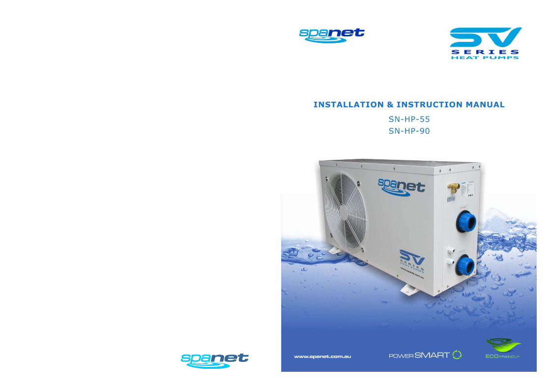
SV Series Heat Pumps
Contents
Specifications ................................................................................................................. 1
Warnings ........................................................................................................................ 2
Introduction ................................................................................................................... 3
Overview ........................................................................................................................ 4
Installation Instructions .................................................................................................. 5
Cable Connections .......................................................................................................... 6
Plumbing Diagram.......................................................................................................... 7
Electrical Wiring Diagram ............................................................................................... 8
SV System Set Up ........................................................................................................... 9
Heat Pump Operation..................................................................................................... 9
Trouble Shooting .......................................................................................................... 10
Maintenance ................................................................................................................ 10
Winterizing the Heat Pump .......................................................................................... 11
Heat Pump Error Codes ................................................................................................ 12
Contact Us .................................................................................................................... 12
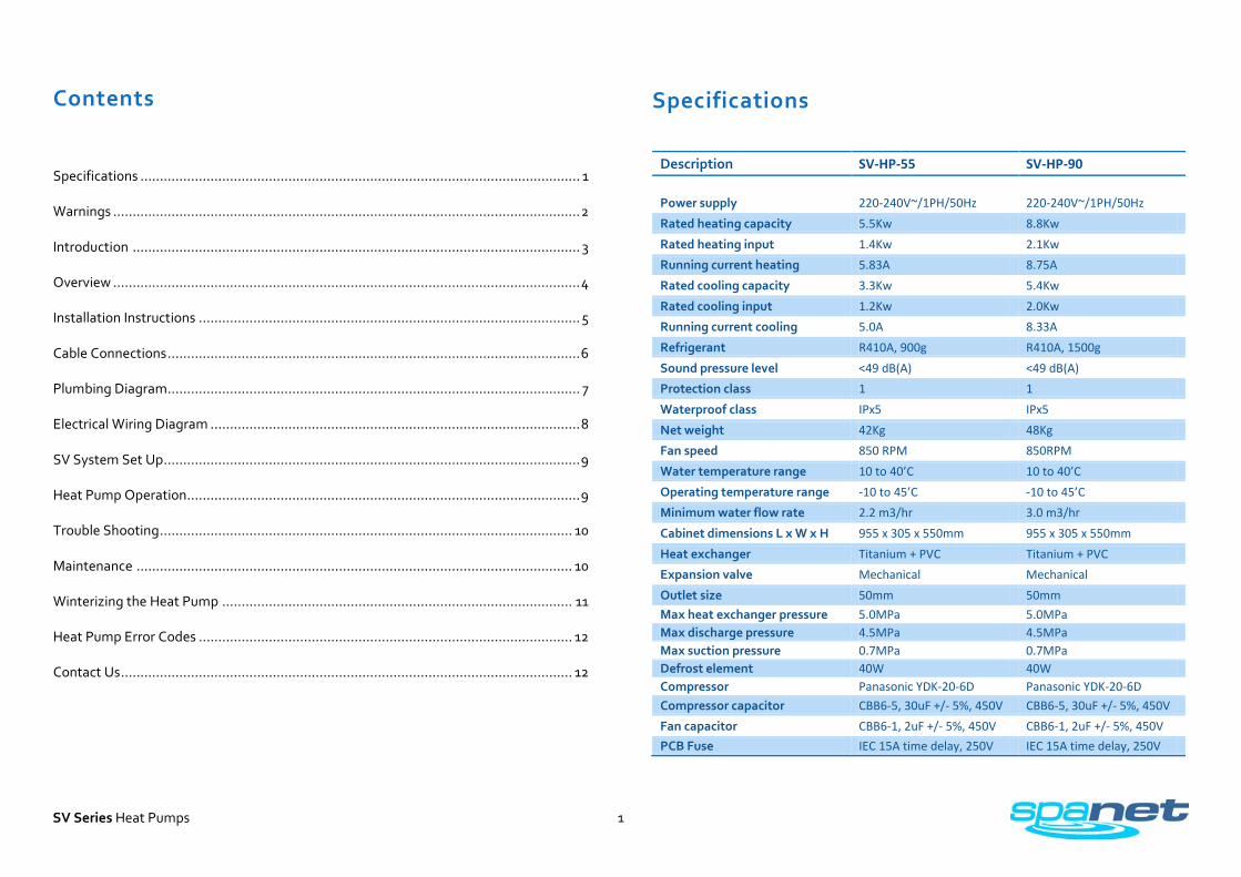
Specifications
Description SV-HP-55 SV-HP-90 Power supply 220-240V~/1PH/50Hz 220-240V~/1PH/50Hz Rated heating capacity 5.5Kw 8.8Kw Rated heating input 1.4Kw 2.1Kw Running current heating 5.83A 8.75A Rated cooling capacity 3.3Kw 5.4Kw Rated cooling input 1.2Kw 2.0Kw Running current cooling 5.0A 8.33A Refrigerant R410A, 900g R410A, 1500g Sound pressure level <49 dB(A) <49 dB(A) Protection class 1 1 Waterproof class IPx5 IPx5 Net weight 42Kg 48Kg Fan speed 850 RPM 850RPM Water temperature range 10 to 40’C 10 to 40’C Operating temperature range -10 to 45’C -10 to 45’C Minimum water flow rate 2.2 m3/hr 3.0 m3/hr Cabinet dimensions L x W x H 955 x 305 x 550mm 955 x 305 x 550mm Heat exchanger Titanium + PVC Titanium + PVC Expansion valve Mechanical Mechanical Outlet size 50mm 50mm Max heat exchanger pressure 5.0MPa 5.0MPa Max discharge pressure 4.5MPa 4.5MPa Max suction pressure 0.7MPa 0.7MPa Defrost element 40W 40W Compressor Panasonic YDK-20-6D Panasonic YDK-20-6D Compressor capacitor CBB6-5, 30uF +/- 5%, 450V CBB6-5, 30uF +/- 5%, 450V Fan capacitor CBB6-1, 2uF +/- 5%, 450V CBB6-1, 2uF +/- 5%, 450V PCB Fuse IEC 15A time delay, 250V IEC 15A time delay, 250V

2
SV Series Heat Pumps
Warnings !!! RISK OF ELECTRICAL SHOCK !!! Please read the following before installing or connecting this appliance
• The heat pump MUST be installed according to the installation instructions AND air space requirements shown in Figure 1 on page 5 of this manual. FAILURE TO FOLLOW THESE INSTALLATION INSTRUCTIONS WILL IMMEDIATELY VOID ANY WARRANTY.
• All electrical connections must be performed by a licensed electrician and must confirm to all national, state and local electrical codes in effect at the time of installation.
• The appliance should be supplied through a residual current device (RCD)
having a rated residual operating current not exceeding 30mA.
• The appliance must be connected to a suitable rated and weather protected power supply. The supply line should be a dedicated power circuit and means for disconnection must be incorporated in the fixed wiring in accordance with your local wiring regulations. Means for disconnection from the supply mains should have a contact separation in all poles that provide full disconnection under over voltage Category III conditions.
• Earthed appliances must be permanently connected to fixed wiring (European models only).
• The appliance contains no serviceable parts. Do not attempt service of this appliance. Contact your dealer or authorized service agent for assistance.
• Turn the mains power OFF before servicing appliance or modifying any cable connection.
• Low voltage or improper wiring may cause damage to this appliance. Read and follow all wiring instructions when connecting to power supply.
• If the supply cord is damaged, it must be replaced by the manufacturer, its
service agent or similarly qualified persons in order to avoid a hazard.
• To prevent electric shock hazard and/or water damage to this appliance, all unused receptacles must have a water proof seal in place.
• Parts incorporating electrical components must be located or fixed so that they cannot fall into the bath or spa.
• Parts containing live parts, except parts supplied with safety extra-low voltage
not exceeding 12V must be inaccessible to a person in the bath or spa.
• This appliance must not be installed in proximity to highly flammable materials.
• Water temperature in excess of 38oC may cause hyperthermia (heat stress).
• It is the installer's responsibility to ensure the floor is capable of supporting the expected load of the bath or spa and an adequate drainage system has to be provided to deal with overflow water.
• A whirlpool spa should incorporate a water filtration system where the required
level of water purity can be achieved.
• An adequate drainage system has to be provided if the equipment is to be installed in a pit.
• Spanet series heat pumps can only be used with Spanet series SV controllers.
• This appliance is not intended for use by persons (including children) with reduced physical, sensory or mental capabilities, or lack of experience and knowledge, unless they have been given supervision or instruction concerning use of the appliance by a person responsible for their safety. Children should be supervised to ensure that they do not play with the appliance.
• When ambient temperatures are close to or under freezing point, water
circulation to the heat pump must never be stopped for more than 4 hours without completely draining the heat exchanger. In areas where freezing conditions are prevalent and sustained, in advance of any freeze event, all water MUST be removed from the entire heat pump water circuit. Refer “Winterising” section on page 11. FREEZE DAMAGE NOT COVERED UNDER PRODUCT WARRANTY

3
SV Series Heat Pumps
Introduction
The SpaNET SV Series consists of a range of spa pool equipment designed to offer complete flexibility to the spa pool builder and user. It is a modular system that allows connection of desired equipment at the spa factory and also allows in field connection should the user wish to expand their system.
The SV Series has at its heart a powerful SV Series Spa Pool Controller (refer below)
Accessory equipment offered in the series are (not limited to): touch pads, lights, pumps, blowers, sensors and heat pumps.
This manual is only concerned with SV Series Heat Pumps. They are designed to be used with only SV Series Spa Controllers. They have no intelligence and can only be controlled by a SV Series Spa Controller.
When installed correctly they offer a truly integrated heat pump solution for a spa pool. They offer outstanding efficiency, low noise and high build quality. They are easy to use and maintain and will provide years of trouble free service.

4
SV Series Heat Pumps
Overview
No. Description 1 Fan protection grid (air outlet) 2 Cabinet 3 Refrigerant charge valve 4 Water outlet 5 Water inlet 6 SV spa controller power cable 7 SV spa controller data cable 9 Condenser
10 Fan 11 Compressor 12 High and Low pressure switches 14 Heat exchanger thermal cut out 15 Four way valve 16 Ambient temperature sensor 17 Condenser temperature sensor 18 Water flow switch 19 Defrost element
1
2
19
3
4
5 6
7

5
SV Series Heat Pumps
Figure 1: Air space requirements
Installation Instructions
The heat pump will be supplied with a data and power cable already fitted. They simply need to be connected to the SV spa controller. Once connected the SV will automatically detect the heat pump and enable its operation. Operation and use of the heat pump is covered in a dedicated section. This section concentrates on the installation of the heat pump and connection of pipe work and cables.
• The SV Series of heat pumps must be located outside in a clean area where noise and air flow will not be disruptive. The heat pump must be located external to the spa pool cabinet to allow sufficient air flow for optimum efficiency.
• The heat pump MUST be installed according to the air space requirements shown in Figure 1, and the instructions as detailed below. FAILURE TO FOLLOW THESE INSTRUCTIONS WILL IMMEDIATELY VOID ANY WARRANTY.
The following pages contain detailed drawings of plumbing, wiring and installation. Please study them carefully before attempting any installation. Select a suitable location in accordance with below notes and consult the local swimming pool safety regulations to check requirements for proximity to other equipment.
1. The heat pump must be situated away from vegetation and obstacles as per Figure 1: Air space requirements.
2. The heat pump must be installed outside, external to the spa cabinet. 3. The heat pump should be mounted on anti vibration mounts on a dead flat/level
base. The base should be a large concrete slab. The base must have sufficient height to prevent entry of water into the bottom of the heat pump. The base must be large and heavy enough to properly secure the heat pump.
4. Height must be adjusted to fit the condensation drain pipe work under the heat pump.
5. Do not install heat pump in a confined space to prevent recycling of air. 6. The fan should not blow towards windows, walls or spaces likely to be inhabited
by people or animals. 7. Do not install where it is likely to be subjected to polluted air, dust or debris etc. 8. The heat pump must operate with a clean air supply. 9. Avoid directing fan output against the dominant wind directions. 10. Protect the heat pump from possible snow fall. 11. Locate heat pump in a place inaccessible by children.
Connection of heat pump
1. Isolate spa power, empty spa water and connect pipe work from the spa to the heat pump ensuring the SV spa controller is plumbed last
in line before the water returns to the spa. Water MUST flow from the heat pump into the SV controller before returning to the spa. DO NOT plumb SV controller prior to heat pump. All pipes should be insulated and secured. Tighten all fittings before opening water shut off valves.
2. Supply power to the spa and operate filtration pump to purge all air from the heat pump and pipe work. Operate the pump for a period of time to check for drips and leaks. Isolate spa power ready for data and power cable connection.
3. Data and power cables must be protected (placed in a protective conduit) between the heat pump and spa pool in accordance with the local wiring regulations. Earth bonding may be required by local wiring regulations and should be installed by a licensed professional. It is best practice to separate data and power cables from each other.

6
SV Series Heat Pumps
Cable Connections
Power cable connection The SV spa controller will have up to two mains power outlets that the heat pump can be connected to. These outlets are not switched, they are always powered. Please refer to the SV Series Installation manual to choose the best AMP socket to use, alternatively contact your sales representative for assistance. NOTE: Phase and controller loading must be considered.
AMP Sockets & Plugs SV series spa controllers utilise AMP mate-N-lok power connectors. The AMP connectors feature a key pattern for fail safe one way connection. When connecting the heat pump be sure to push cordset firmly into socket and ensure both side locking taps have been secured and latched in place. Once power and data cables have been connected power can be restored to the spa pool. The SV controller will detect that the heat pump has been connected and will automatically engage it for heating and cooling functions based on factory default settings.
Some settings may be adjusted to tailor the heat pump operation for the customer’s needs. Refer to SV Controller Heat Pump Set Up section for more detail.
Data Cable Connection Unscrew and remove low voltage connections cover from spa pack enclosure Connect data cable RJ45 plug into EXP2 socket (refer aside)
Route the keypad cable through the cable guide provided Ensure the keypad cable has a drip loop before it enters the enclosure

7
SV Series Heat Pumps
Plumbing Diagram
IMPORTANT NOTE: The SV controller must be plumbed AFTER the heat pump (refer picture below). Water must flow out of the heat pump and through the SV controller before returning to the spa.

8
SV Series Heat Pumps
Electrical Wiring Diagram
SV Series Heat Pumps are supplied pre-wired. No additional wiring is required. This drawing is supplied for informative purposes only.
Fuse = IEC 15A Time delay, 250V
9
SV Series Heat Pumps
SV System Set Up
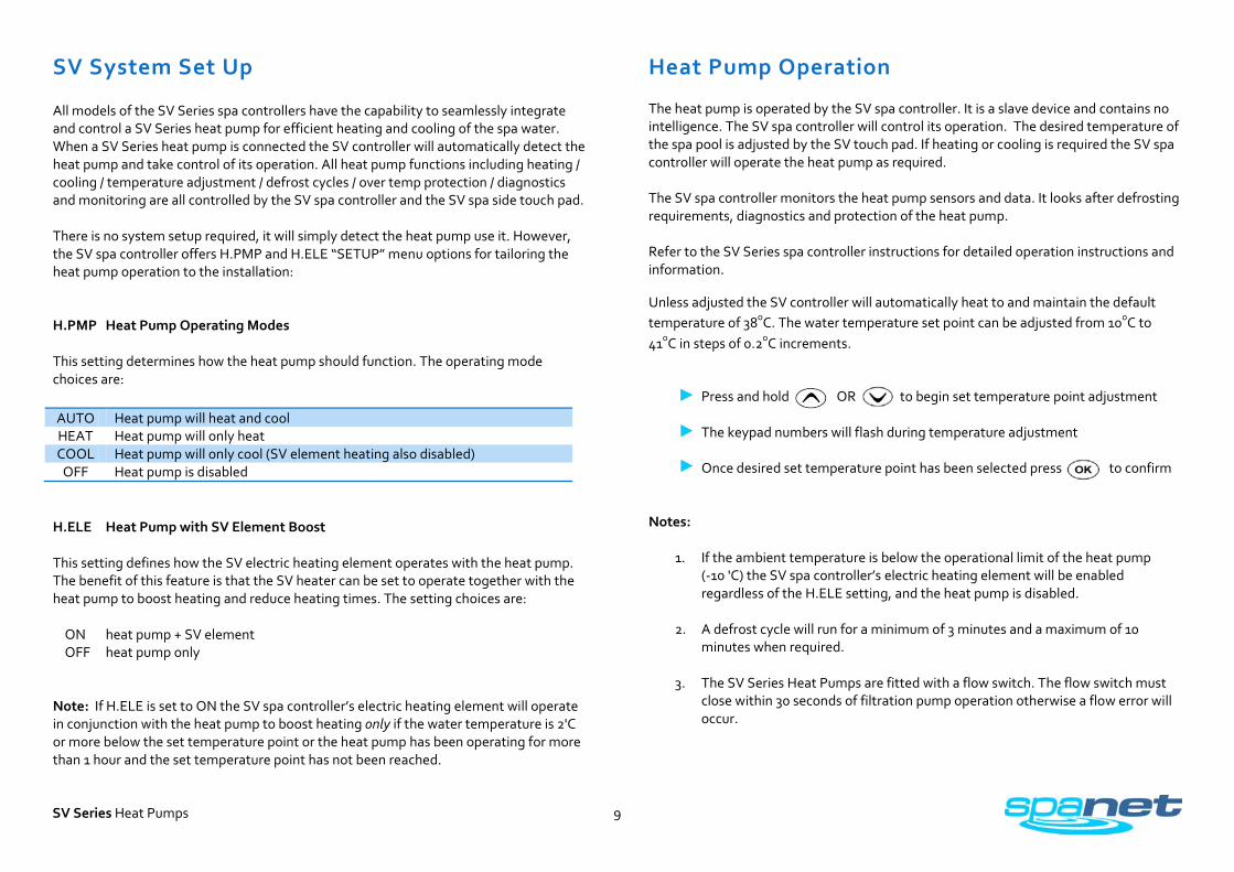
All models of the SV Series spa controllers have the capability to seamlessly integrate and control a SV Series heat pump for efficient heating and cooling of the spa water. When a SV Series heat pump is connected the SV controller will automatically detect the heat pump and take control of its operation. All heat pump functions including heating / cooling / temperature adjustment / defrost cycles / over temp protection / diagnostics and monitoring are all controlled by the SV spa controller and the SV spa side touch pad. There is no system setup required, it will simply detect the heat pump use it. However, the SV spa controller offers H.PMP and H.ELE “SETUP” menu options for tailoring the heat pump operation to the installation: H.PMP Heat Pump Operating Modes This setting determines how the heat pump should function. The operating mode choices are: AUTO Heat pump will heat and cool HEAT Heat pump will only heat COOL Heat pump will only cool (SV element heating also disabled)
OFF Heat pump is disabled H.ELE Heat Pump with SV Element Boost This setting defines how the SV electric heating element operates with the heat pump. The benefit of this feature is that the SV heater can be set to operate together with the heat pump to boost heating and reduce heating times. The setting choices are: ON heat pump + SV element OFF heat pump only Note: If H.ELE is set to ON the SV spa controller’s electric heating element will operate in conjunction with the heat pump to boost heating only if the water temperature is 2'C or more below the set temperature point or the heat pump has been operating for more than 1 hour and the set temperature point has not been reached.
Heat Pump Operation The heat pump is operated by the SV spa controller. It is a slave device and contains no intelligence. The SV spa controller will control its operation. The desired temperature of the spa pool is adjusted by the SV touch pad. If heating or cooling is required the SV spa controller will operate the heat pump as required. The SV spa controller monitors the heat pump sensors and data. It looks after defrosting requirements, diagnostics and protection of the heat pump. Refer to the SV Series spa controller instructions for detailed operation instructions and information.
Unless adjusted the SV controller will automatically heat to and maintain the default temperature of 38oC. The water temperature set point can be adjusted from 10oC to 41oC in steps of 0.2oC increments.
Press and hold OR to begin set temperature point adjustment
The keypad numbers will flash during temperature adjustment
Once desired set temperature point has been selected press to confirm
Notes:
1. If the ambient temperature is below the operational limit of the heat pump (-10 'C) the SV spa controller’s electric heating element will be enabled regardless of the H.ELE setting, and the heat pump is disabled.
2. A defrost cycle will run for a minimum of 3 minutes and a maximum of 10
minutes when required.
3. The SV Series Heat Pumps are fitted with a flow switch. The flow switch must close within 30 seconds of filtration pump operation otherwise a flow error will occur.

10
SV Series Heat Pumps
Trouble Shooting
Should a problem occur the SV spa controller will shut down and disable the heat pump.
There are no user serviceable parts inside the heat pump. If a problem occurs please contact a licensed professional for service.
Water leaking from unit
Heat pump operation in heating or defrost mode will cause condensation on the condenser, this is normal. The condensation will collect in the base of the machine and exit via the drain pipe under the machine. Confirm that drain pipe work is not blocked and that the machine is mounted on a level surface.
If water leaking from the machine is not from condensation then all pipe work and connections should be checked for damage and leaks.
No heat pump operation
Check that the heat pump has power from the SV spa controller. Confirm the data cable is connected to the heat pump and SV spa controller. Check cables for signs of damage. Check the fuse located on the internal heat pump PCB.
Check SV spa controller settings. Confirm that P.PMP setting has not disabled the heat pump. Confirm ambient air temperature is within operational limits.
Flow error
The flow switch must close within 30 seconds of filtration pump operation. Check that the heat pump is connected to the correct water pump. Check there is adequate water flow. Check water pump operation for internal thermal cut out operation or motor stall. Check spa filters and shut off valves.
Thermal cut out errors
Check for poor water pump flow performance. Confirm ambient air temperatures are with operational limits.
Maintenance
Little maintenance is required however the following should be performed on a regular basic to ensure long equipment service life.
When performing maintenance isolate power to the spa pool and heat pump for safety.
Clean condenser using a very soft brush and water containing a mild detergent. This will remove any built up dust and grime and help to restore maximum efficiency.
Wash the exterior of the cabinet using an automotive detergent. Remove any moss/mould or other growth. Check the cabinet for signs of corrosion or damage and remedy them. Touch up any scratches or chips in paint work and apply a coat of automotive wax to the cabinet exterior.
Check condensation drain pipe work is clean and clear.
Inspect cables and pipe work for signs of damage or wear. Replace if necessary.
Inspect securing bolts for tightness and corrosion.
Ensure that air space surrounding the heat pump is clear. Remove any impending vegetation or objects.
Note: Should the unit vibrate more than usual or emit strange noises contact a licensed professional for service.

11
SV Series Heat Pumps
Winterizing the Heat Pump
Winterizing is a procedure that prepares your heat pump for freezing conditions. In areas where freezing conditions are a rare and brief occurrence, the water filtration system can be programmed to run continuously throughout the freeze period. Typically, during light freeze conditions circulating (moving) water will not solidify.
However in areas where freezing conditions are prevalent and sustained, and the spa is to be turned OFF during the winter period, in advance of any freeze event, all water MUST be removed from the entire heat pump water circuit including heat exchanger. Freezing of the unit will severely damage the heat exchanger and other components due to water/ice expansion. Damage resulting from a failure to properly winterize is NOT
Preparing for Light Freeze Conditions
covered under the heat pump product warranty.
When ambient temperatures are close to or under freezing point, water circulation to the heat pump must never be stopped for more than 4 hours. To ensure this certain SV “SETUP” menu software options should to adjusted/checked prior to occurrence of light freeze events. Carry out the following:
1. Disable sleep timers a. Press and hold UP and DOWN buttons simultaneously until [MODE] is displayed b. Press DOWN button to skip through menu items until [SNZE] is displayed c. Press OK button to enter SNZE adjustment, [1.SNZ] is displayed d. Press OK button to enter 1.SNZ (first sleep timer) programming e. Press UP or DOWN button to adjust 1.DAY setting until the semicolon [ : ]
DISABLED sleep timer icon is displayed f. Press OK to confirm and save setting g. Re-enter SNZE menu and ensure 2.SNZ (second sleep timer) is also disabled [ : ]
2. Set filtration to 24 hr circulation
a. Press and hold UP and DOWN buttons simultaneously until [MODE] is displayed b. Press UP button to skip setup menu to filtration [FILT] menu option c. Press OK button to enter filtration [FILT] adjustment d. Press UP button to increase daily filtration time to twenty-four hours [24 HR] e. Press OK to confirm and save setting
Preparing for Freezing Conditions
If the heat pump is located in an area where the temperature drops below the freezing point of 0˚C, and the spa is to be shut down and turned OFF for the winter period, it is mandatory that the water accumulated in the heat pump be drained completely before freezing weather occurs. To prevent damage from freezing perform the following steps:
1. Switch power to spa OFF. 2. Disconnect heat pump power and data cables from the SV controller. 3. Shut off all heat pump water isolating valves to close the water supply to the
heat pump. 4. Drain the heat exchanger by removing the heat exchanger drain plug found on
the back of the unit. 5. Disconnect water inlet and outlet coupler fittings and completely drain pipe
work of all water. 6. It is recommended to flush the inside of the heat exchanger with a garden hose
and to drain the unit again. 7. Replace drain plug and loosely re-attach inlet and outlet couplers to prevent
lost parts and insect / debris ingress. 8. If the spa has been plumbed to run independently from the heat pump, alter by-
pass valves according and switch power to spa ON again if desired. Restarting the heat pump after winter:
1. Switch power to spa OFF. 2. Check heat exchanger drain plug is correctly installed and water inlet and outlet
coupler fittings are tight. 3. Open all water shut off valves and alter by-pass valves if required. 4. Supply power to the spa and operate filtration pump to purge all air from the
heat pump and pipe work. Operate the pump for a period of time to check for drips and leaks.
5. Switch power to spa OFF again, ready for data and power cable connection. 6. Connect heat pump power and data cables to SV controller. 7. Switch power to spa ON again.
NOTE: FREEZE DAMAGE NOT COVERED UNDER PRODUCT WARRANTY

12
SV Series Heat Pumps
Heat Pump Error Codes If a heat pump fault condition is detected a warning message is scrolled across the SV Series Spa Controller touch pad LCD every 60 seconds and the heat pump is disabled. Spa operation will continue however the spa will now heat with the SV spa controller’s electric heating element and there will be no ability to cool the water. The heat pump warning message will continue to scroll every 30~60 seconds, and the heat pump will remain disabled until the mains power is turned OFF and back ON again. If after resetting mains power the fault condition persists please contact your spa reseller and report the warning message that is shown. A list of the fault conditions and warning messages are detailed below for reference. WARNING MESSAGE DESCRIPTION
“HEAT PUMP AMB” Ambient thermistor temperature sensor error
“HEAT PUMP COND” Condenser thermistor temperature sensor error
“HEAT PUMP FLOW” Water flow not detected
“HEAT PUMP LOW P” Compressor low pressure switch open
“HEAT PUMP HIGH P” Compressor high pressure switch open
“HEAT PUMP COMP” Compressor thermal cut out open
“HEAT PUMP EXCH” Heat exchanger thermal cut out open
IMPORTANT NOTE
If a heat pump encounters an error the heat pump will remain disabled until the mains power is turned OFF and back ON again. The heat pump warning message will continue to scroll every 30~60 seconds until the power is reset
Contact Us
Spa Net Pty Ltd Unit 4 103 Railway Road North Mulgrave NSW 2756 Australia Phone: +61 2 4587 7766 Fax: +61 2 4587 8766 www.spanet.com.au Technical Support & Service [email protected] Accounts Department [email protected] Sales Department [email protected]