Suspension Strut Bearings - Welcome to the Schaeffler … bearings form part of the wheel suspension...
15
Suspension Strut Bearings Rolling Bearings and Components for Passenger Car Chassis Automotive Product Information API 08
Transcript of Suspension Strut Bearings - Welcome to the Schaeffler … bearings form part of the wheel suspension...

Suspension Strut BearingsRolling Bearings and Components for Passenger Car Chassis
Automotive Product Information API 08

This publication has been produced with a great deal of care, and all data have been checked for accuracy. However, no liability can be assumed for any incorrect or incomplete data.
Product pictures and drawings in this publication are for illustration only and are not intended as an engineering design guide.Applications must be developed only in accordance with the technical information, dimension tables, and dimension drawings contained in this publication.Due to constant development of the product range, we reserve the right to make modifications.
The terms and conditions of sale and delivery underlying contracts and invoices shall apply to all orders.
Produced by:INA-Schaeffler KG91072 Herzogenaurach (Germany)Mailing address:Industriestrasse 1–391074 Herzogenaurach (Germany)© by INA · May 2002All rights reserved.Reproduction in whole or in part without our authorization is prohibited.Printed in Germany by:Mandelkow GmbH, 91074 Herzogenaurach (Germany)
Strut bearings form part of the wheel suspension in independent suspension systems. The wheel suspension has the task of ensuring maximum driving safety and ride quality while providing accurate steering. It must also transfer tire-road contact forces to the vehicle frame and isolate the body from road noise, while being as lightweight as possible.
To accomplish these objectives, the components in the suspension system must be correctly matched to one another, which requires close cooperation between the suspension or chassis manufacturer and the system supplier.
Proven competence and experience in the design, analysis, and manufacture of suspension strut bearings have long established INA as a winning partner in designing solutions for a wide range of technical applications.
Working closely with customers, INA has developed strut bearings that:� Absorb radial and axial forces� Ensure low-friction and distortion-free movement of the shock-
absorber spring during steering and deflection, enabling the spring to operate without self-aligning torque
� Locate the shock-absorber spring and form a support surface for full deflection of the shock absorber
� Can be used with coupled and uncoupled suspension struts
� Are rigid and lightweight� Help isolate the body from road noise
� Have a compact design that has been optimized for limited mounting space and are supplied as a sealed unit
� Are easy to assemble and can be installed using robots
� Are maintenance-free
Extensive testing using special test rigs and defined test standards, as well as stringent process and function controls, ensure that all customer requirements are met.
Suspension strut bearings from INA represent chassis components that contribute substantially to the comfortable, safe, reliable, and economical operation of automobiles around the world.
INA-Schaeffler KGHerzogenaurach (Germany)
Suspension Strut Bearings
4
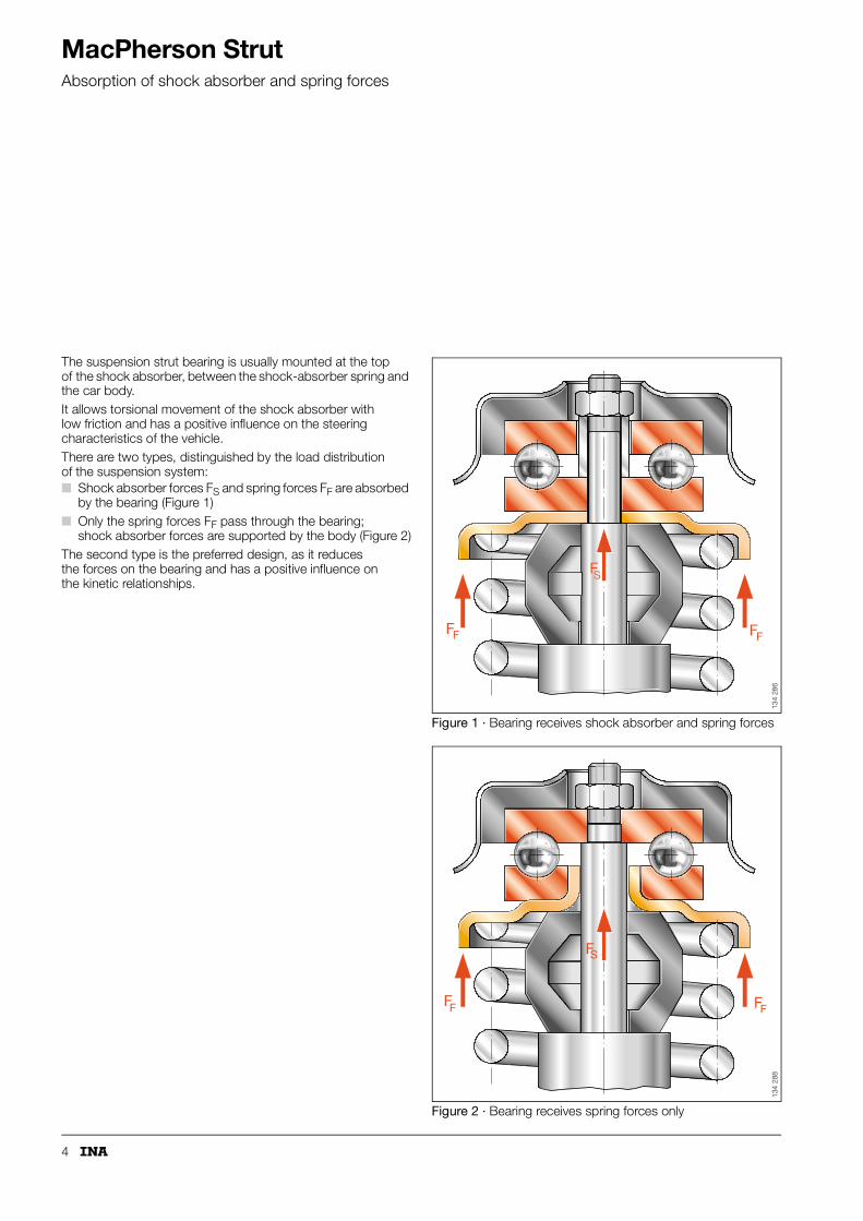
MacPherson StrutAbsorption of shock absorber and spring forces
The suspension strut bearing is usually mounted at the top of the shock absorber, between the shock-absorber spring and the car body. It allows torsional movement of the shock absorber with low friction and has a positive influence on the steering characteristics of the vehicle. There are two types, distinguished by the load distribution of the suspension system:� Shock absorber forces FS and spring forces FF are absorbed
by the bearing (Figure 1)� Only the spring forces FF pass through the bearing;
shock absorber forces are supported by the body (Figure 2)The second type is the preferred design, as it reduces the forces on the bearing and has a positive influence on the kinetic relationships.
Figure 1 · Bearing receives shock absorber and spring forces
Figure 2 · Bearing receives spring forces only
F
F
F FF
S
134
286
F
F
F FF
S
134
288
5
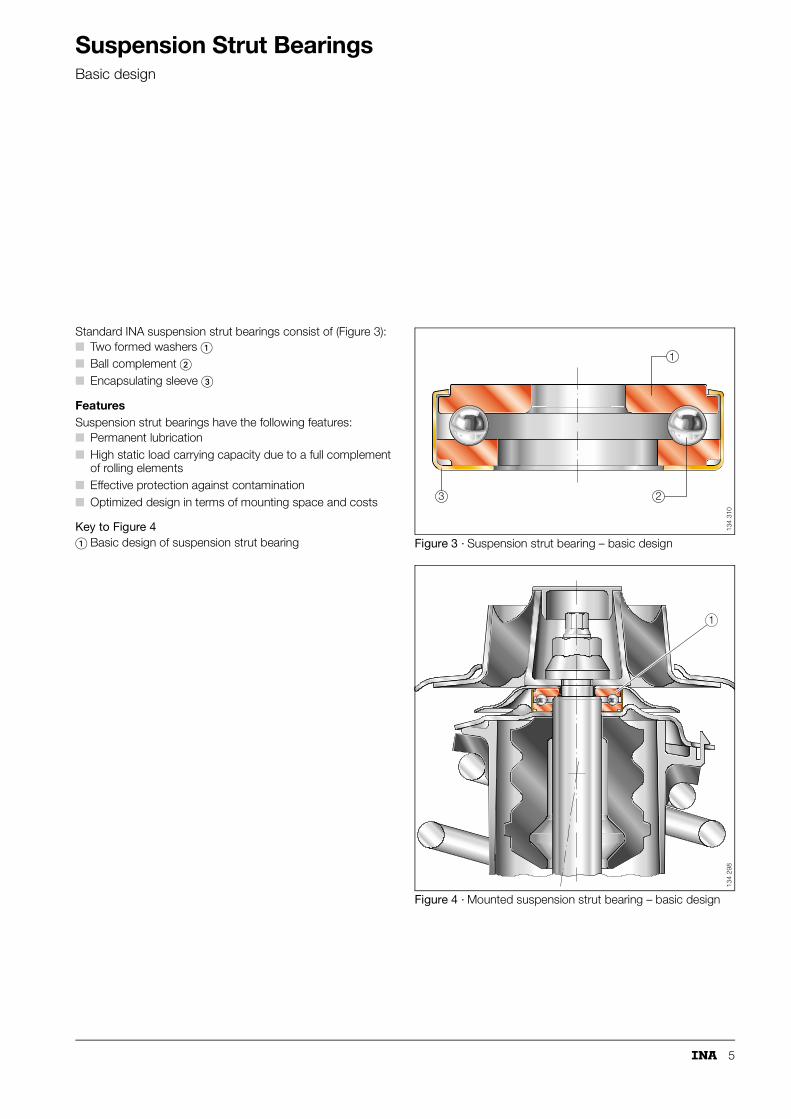
Suspension Strut BearingsBasic design
Standard INA suspension strut bearings consist of (Figure 3):� Two formed washers �� Ball complement �� Encapsulating sleeve �
FeaturesSuspension strut bearings have the following features:� Permanent lubrication� High static load carrying capacity due to a full complement
of rolling elements� Effective protection against contamination� Optimized design in terms of mounting space and costs
Key to Figure 4Figure 3 · Suspension strut bearing – basic design
Figure 4 · Mounted suspension strut bearing – basic design
� Basic design of suspension strut bearing
23
1
134
310
1
134
298
6
Suspension Strut Bearings
Design with thrust angular-contact ball bearing
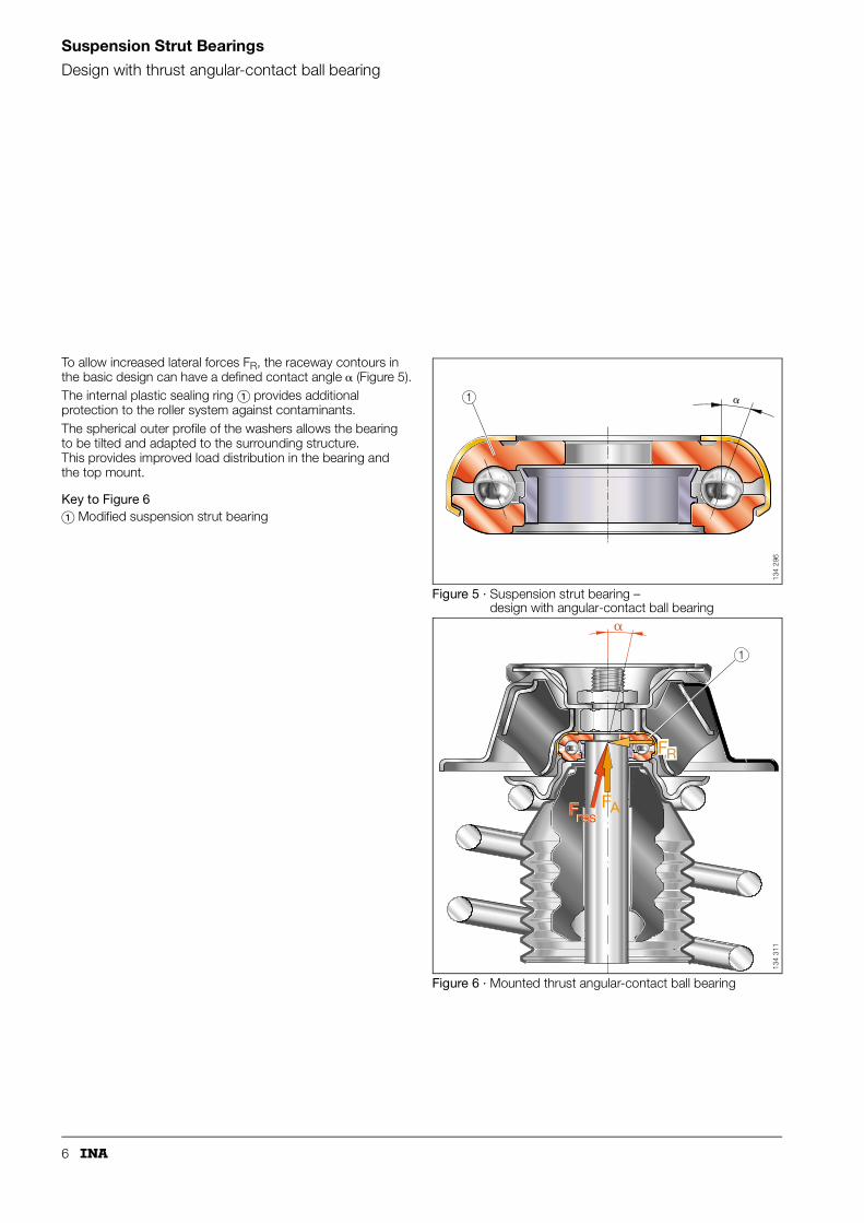
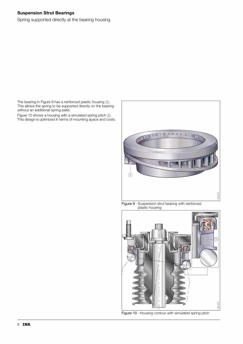
To allow increased lateral forces FR, the raceway contours in the basic design can have a defined contact angle � (Figure 5).The internal plastic sealing ring � provides additional protection to the roller system against contaminants. The spherical outer profile of the washers allows the bearing to be tilted and adapted to the surrounding structure. This provides improved load distribution in the bearing and the top mount.
Key to Figure 6
Figure 5 · Suspension strut bearing – design with angular-contact ball bearing
Figure 6 · Mounted thrust angular-contact ball bearing
� Modified suspension strut bearing
�1
134
296
�
FAFresFres
1
FR13
4 31
1

7
Suspension Strut Bearings
Design trendEncapsulated suspension strut bearing
In the development of suspension struts, there is a tendency toward the use of shock-absorber springs with larger diameters.As a result, full-complement bearings with small pitch diameter are being replaced by larger cage-guided suspension strut bearings (Figure 7, �).These bearings are encapsulated in plastic housings, which protect them from contaminants. The cage provides an adequate grease reservoir, and the grease ensures a longer service life of the bearings.The variable design of the plastic parts allows them to be adapted to the surrounding structure.The spring can be supported directly on the bearing if the lower housing is sufficiently rigid. In this case, the spring support plate is not required.Figure 8 shows the spring supported by a spring plate �.
Figure 7 · Design trend
Figure 8 · Spring supported by spring plate – encapsulated suspension strut bearing
1
134
293
1
134
314
8
Suspension Strut Bearings
Spring supported directly at the bearing housing
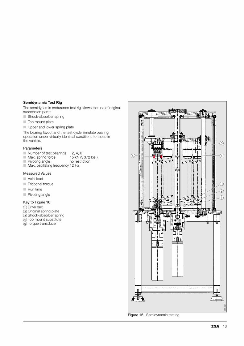
The bearing in Figure 9 has a reinforced plastic housing �. This allows the spring to be supported directly on the bearing without an additional spring plate. Figure 10 shows a housing with a simulated spring pitch �. This design is optimized in terms of mounting space and costs.
Figure 9 · Suspension strut bearing with reinforced plastic housing
Figure 10 · Housing contour with simulated spring pitch
1
134
313
1
134
312

9
In this design the spring is also supported directly by the bearing housing (Figure 11).The housing has extra reinforcement to support the spring and full deflection of impact forces.
Key to Figure 11
Figure 11 · Reinforced bearing housing capable of supporting spring and full deflection forces
� Top mount� Suspension strut bearing with reinforced housing� Bump stop
1
2
3
134
320

10
Suspension Strut Bearings
Design overview
Figure 12 · Suspension strut bearing types
134
346

11
Suspension Strut Bearings
Calculation
Modern developments in rolling bearing technology would be inconceivable without an FE analysis of the bearing and the adjacent components. The goal in the development of rolling bearings is to achieve the best possible design in terms of rigidity, mounting space, and costs (Figure 13).For this analysis, the exact load distribution at the interface of the bearing and the shock-absorber spring must be determined. INA has developed a procedure to determine the forces in relation to the original springs. Figure 14 shows the measured load distribution on a suspension strut bearing.
Figure 13 · FE analysis of the bearing housing rigidity
Figure 14 · Load distribution on the suspension strut bearing
13
2
Fax = 4038 N
latF = 740 N
134
317a
0
0
510
1520
3025
3540
510
15
20
30
25
35
40
876
54321
0
87654321
Forc
e
Forc
e
Rows
Col
umns
134
347

12
Suspension Strut Bearings
Testing – test rigs
Endurance Test RigAfter calculations and design, prototype bearings are subjected to the following tests: � Frictional torque measurements� Test of static load carrying capacity� Endurance tests� Leak testsFigure 15 shows the basic type of endurance test rig.
Parameters
Measured Variables� Axial force� Pivoting angle� Run time� Frictional torque
Key to Figure 15 Figure 15 · Endurance test rig
� Number of test bearings 2, 4, 6� Max. oscillating frequency 10 Hz� Max. pivoting angle 45°� Max. axial load 8 kN (1798 lbs.)� Max. tilting 15°
� Disk springs� Adapter for oscillating drive� External bearing seat with angular adapter� Tilting of the suspension strut bearing� Suspension strut bearing
321
54
134
323
13
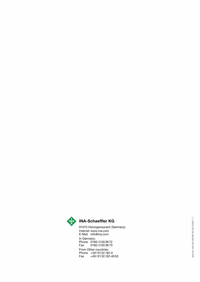
Semidynamic Test RigThe semidynamic endurance test rig allows the use of original suspension parts: � Shock-absorber spring� Top mount plate� Upper and lower spring plateThe bearing layout and the test cycle simulate bearing operation under virtually identical conditions to those in the vehicle.
Parameters
Measured Values� Axial load� Frictional torque� Run time� Pivoting angle
Key to Figure 16
Figure 16 · Semidynamic test rig
� Number of test bearings 2, 4, 6� Max. spring force 15 kN (3 372 lbs.)� Pivoting angle no restriction� Max. oscillating frequency 12 Hz
� Drive belt� Original spring plate� Shock-absorber spring� Top mount substitute� Torque transducer
3
44
5
2
1
065
024

14
Suspension Strut Bearings
Testing – test rigs
Leak Test RigThis test rig is used to test the effectiveness of the suspension strut bearing seal (Figure 17).The bearings are sprayed with water or saltwater solution in the test chamber while in motion and under load.Parameters
Measured variables� Frictional torque� Oscillating frequency� Corrosion status
Figure 17 · Leak test rig
� Oscillating frequency 1.5 Hz� Max. axial load 5 kN (1124 lbs.)� Pivoting angle 8° to 40°� Spray cycles programmable dry/saltwater solution
065
026
INA-Schaeffler KG91072 Herzogenaurach (Germany)Internet www.ina.comE-Mail [email protected] Germany:Phone 0180 /5 00 38 72Fax 0180 /5 00 38 73From Other countries:Phone +49 / 9132 /82-0Fax +49 / 9132 /82-49 50 S
ach-
Nr.
004-
040-
384/
AP
I 08
US
-D 0
5021