Susitna-Watana Hydroelectric Project Document ARLIS Uniform … · · 2017-08-18Susitna-Watana...
192
Alaska Resources Library & Information Services Susitna-Watana Hydroelectric Project Document ARLIS Uniform Cover Page Title: Susitna RCC dam cost evaluation : final SuWa 197 Author(s) – Personal: Author(s) – Corporate: Prepared by R & M Consultants, Inc. [and] Hatch Acres [and] Jack Linnard [i.e. Linard] Consulting AEA-identified category, if specified: AEA-identified series, if specified: Series (ARLIS-assigned report number): Susitna-Watana Hydroelectric Project document number 197 Existing numbers on document: Published by: [Anchorage, Alaska : Alaska Energy Authority, 2009] Date published: November 16, 2009 Published for: Date or date range of report: Volume and/or Part numbers: Final or Draft status, as indicated: Final Document type: Pagination: [191] p. Related work(s): Has supplement: Susitna Project supplemental report, low Watana Dam RCC concept cost evaluation : final. (SuWa 216) Pages added/changed by ARLIS: Notes: From the Alaska Energy Authority's Susitna Reports webpage (September 23, 2013). All reports in the Susitna-Watana Hydroelectric Project Document series include an ARLIS- produced cover page and an ARLIS-assigned number for uniformity and citability. All reports are posted online at http://www.arlis.org/resources/susitna-watana/
-
Upload
nguyenkhue -
Category
Documents
-
view
215 -
download
1
Transcript of Susitna-Watana Hydroelectric Project Document ARLIS Uniform … · · 2017-08-18Susitna-Watana...

Alaska Resources Library & Information Services
Susitna-Watana Hydroelectric Project Document ARLIS Uniform Cover Page
Title: Susitna RCC dam cost evaluation : final
SuWa 197
Author(s) – Personal: Author(s) – Corporate: Prepared by R & M Consultants, Inc. [and] Hatch Acres [and] Jack Linnard [i.e. Linard] Consulting
AEA-identified category, if specified: AEA-identified series, if specified: Series (ARLIS-assigned report number): Susitna-Watana Hydroelectric Project document number 197
Existing numbers on document:
Published by: [Anchorage, Alaska : Alaska Energy Authority, 2009]
Date published: November 16, 2009
Published for:
Date or date range of report:
Volume and/or Part numbers:
Final or Draft status, as indicated: Final
Document type:
Pagination: [191] p.
Related work(s): Has supplement: Susitna Project supplemental report, low Watana Dam RCC concept cost evaluation : final. (SuWa 216)
Pages added/changed by ARLIS:
Notes: From the Alaska Energy Authority's Susitna Reports webpage (September 23, 2013).
All reports in the Susitna-Watana Hydroelectric Project Document series include an ARLIS-produced cover page and an ARLIS-assigned number for uniformity and citability. All reports are posted online at http://www.arlis.org/resources/susitna-watana/
Susitna ProjectSusitna Project
WatanaWatana and High Devil Canyonand High Devil CanyonWatanaWatana and High Devil Canyonand High Devil Canyon
RCC Dam Cost EvaluationRCC Dam Cost Evaluation
FinalFinalNovember 16, 2009November 16, 2009
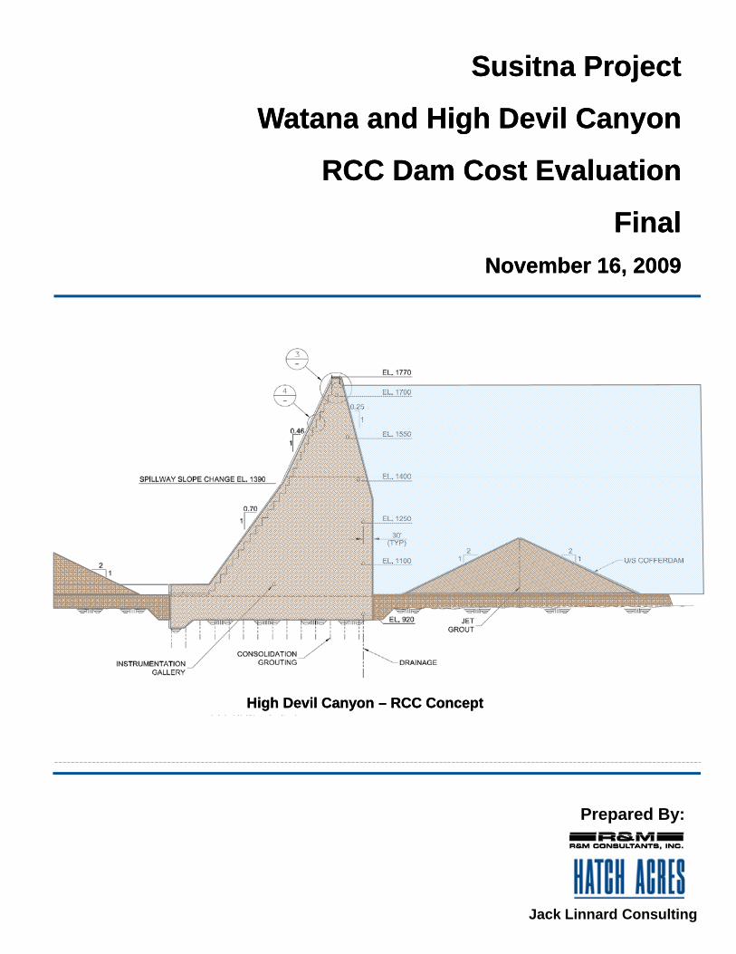
High Devil Canyon High Devil Canyon –– RCC ConceptRCC Concept
Prepared By:
Jack Linnard Consulting

SSWWRRFFNN Susitna ProjeSusitna ProjeW
atanaW
atanaand and
RC
C D
am C
oR
CC
Dam
Co
FinalFinalN
ovember 16,
Novem
ber 16, ectectH
igh Devil C
High D
evil Cost Evaluatioost Evaluatio
20092009
Canyon
Canyon
onon
Prepared By:
High Devil Canyon High Devil Canyon –– RCC ConceptRCC Concept
Jack Linnard Consulting

Susitna ProjectSusitna Project
WatanaWatana and High Devil Canyonand High Devil CanyonWatanaWatana and High Devil Canyonand High Devil Canyon
RCC Dam Cost EvaluationRCC Dam Cost Evaluation
FinalFinalNovember 16, 2009November 16, 2009
High Devil Canyon High Devil Canyon –– RCC ConceptRCC Concept
Prepared By:
Jack Linnard Consulting
11/16/09
Susitna RCC Dam Cost Evaluation
Final
November 16, 2009
Prepared by: R&M Consultants
Hatch Acres Jack Linnard Consulting

R&M Consultants - Hatch Acres AEA – Susitna RCC Dam Cost Evaluation
11/17/2009 1/95 FINAL
EXECUTIVE SUMMARY At the time of the Susitna Project studies studies for the 1983 FERC License Application and 1985 amendment to the License Application, roller compacted concrete (RCC) texchnology was not regarded as sufficiently developed to use in the construction of large dams. Over the past 30 years, however, roller compacted concrete has developed as a construction material for dams of increasing size and techniques of material placement and composition of the RCC mix has been refined with experience. The Alaska Energy Authority is considering materials of construction for the Watana and High Devil Canyon dams other than using earth embankment and rockfill structures and has identified roller compacted concrete as having potential for cost savings in construction of Susitna project dams. R&M Consultants study team (R&M) was engaged by the Alaska Energy Authority (AEA) to develop a conceptual design and perform concept level cost estimates for a RCC dam at the Watana site and at the High Devil Canyon site. The study was scoped to consider the full height Watana and High Devil Canyon RCC dams to be mutually exclusive single dam operations and the costs to be based on taking the organization and results of the 1982 Acres Feasibility Study updated to December 2008 dollars as sufficient for the purposes of the current concept study. In conducting the study we reviewed the environmental conditions reported in the 1983 and 1985 FERC license applications and associated environmental studies at the sites including reviewing the hydrology, geology and seismicity for the Watana and High Devil Canyon locations and found present conditions to be consistent with that reported. It is noted that the geology at the HDC site is drawn from the general geologic studies of the Susitna Project and the conditions at the High Devil Canyon site reported in the 1974 Kaiser report. The Watana RCC dam cost estimate utilizes the information and the format of the 2008-based cost estimate HDR/DTA updated to the extent that it is possible to maintain an “apples to apples” comparison of the concepts. In areas where there are modifications to the earth embankment dam project due to the alternate RCC dam configuration, new quantities and unit prices were developed reflecting the change in technology. We have stated costs of the RCC concepts in December 2008 dollars to be consistent with the HDR/DTA cost estimate.
The cost estimate summary, Table ES-1, summarizes the estimated cost of the Watana RCC dam and High Devil Canyon RCC dam options. A detailed summary of costs is presented in Appendix B and detailed costs are included in Appendix C for Watana RCC dam and Appendix D for High Devil Canyon RCC dam. The cost estimates focus on the RCC dam and scales the cost of project features/facilities such as the power tunnel/power conduits, powerhouse, switchyards, transmission lines, site road and rail access, operations support facilities and similar features as they are affected by details of the RCC dam options.

R&M Consultants - Hatch Acres AEA – Susitna RCC Dam Cost Evaluation
11/17/2009 2/95 FINAL
In developing the RCC dam costs, the access tunnels, underground powerhouse and hydraulic works in the Watana 2008 basis estimate were retained for both of the RCC dams and both RCC concepts studied have been estimated with identical 1200 megawatts of installed capacity in the powerhouses. The use of RCC allows different project arrangements for project facilities including cofferdams, spillway, intakes, water conveyances and powerhouse that could provide additional cost savings potential. The use of a surface powerhouse with short penstocks at both of the RCC dams has potential for substantial saving in cost due to elimination of a large amount of underground work for access and hydraulic tunnels and chambers and powerhouse but the surface powerhouse concept was not developed due to not being in the scope of the present study which concentrated mainly on the RCC dam structure and surface access and support requirements. Costs of RCC materials and a conceptual design for the prospective RCC dams was based on experience in the past decade at other locations in the world where RCC dams have been constructed, particularly dams in the height class of the full height Watana dam and High Devil Canyon dam which are in the 800 to 1,000-foot high class. It is noted that RCC dams have been constructed in Mongolia and other cold regions locations. We have found no fatal flaw in the basic concept of building the Full Watana Dam or High Devil Canyon dam using RCC (detailed geologic investigation, including drilling, at the HDC site is needed to confirm no fatal geological flaw exists at that site as our study is based on data from the 1974 Kaiser report as mentioned above). We estimate that the RCC option offers a potential reduction in capital cost compared with the embankment dam option. Our cost analysis has made as direct a comparison as is reasonably possible between the estimated costs of the RCC option and the embankment option, and we the embankment option at Watana is estimated to require 6 years to construct after completion of diversion construction. We estimate the capital cost on the same basis (December 2008 dollars) for the Watana RCC dam is $6.6 billion and will require 4.5 to 5 years to construct after diversion and the High Devil Canyon RCC alternative is $5.4 billion and will require 3.5 to 4 years to construct after diversion based on volumes and production rate of a large RCC production installation. Optimization of the RCC design will almost certainly result in a further decrease in the estimated cost of construction in particular the use of a surface powerhouse mentioned above would significantly reduce the amount of subsurface work and potentially shorten the construction schedule. It is noted that, if built using RCC, either the Full Watana Dam or High Devil Canyon would set a new precedent for height of an RCC dam, and there will inevitably be some associated risk. Further study of the concept is required to understand the issues associated with an RCC dam of this size at these sites. It is possible that developing the RCC concept to its final design configuration and moving toward construction could result in development opportunities for basic industries in Alaska in producing cement and pozzolans and perhaps fly ash. Access and logistical considerations including road, rail and air transport are of concern at a remote site such as the Susitna Project sites. Housing for Owner representatives, engineering, scientific and

R&M Consultants - Hatch Acres AEA – Susitna RCC Dam Cost Evaluation
11/17/2009 3/95 FINAL
construction personnel, over the life of the project construction is assumed to be in modern long term type camp accommodations that meet current codes and standards for these type facilities. Provision of on-site medical and recreational facilities and support for workers under the federal and state regulations is an important consideration. If AEA determines to move forward with the Susitna Project it is imperative that a preliminary Notice of Intent be filed with FERC at the earliest possible date under the Alternative Licensing procedure (ALP). Permitting for the project by FERC requires regulatory compliance issues be resolved satisfactorily as early as possible. The time required to review and confirm the results of environmental and regulatory matters is significant but we feel can be shortened by addressing as soon as possible the pertinence of the regulatory issues and draft settlement agreements as of the 1985 final project report(s) through records searches and obtaining Agency support and participation to address the issues and seek FERC and agency agreement that a short licensing review can be done ASAP. We recommend a two-year precursor program to pursue the objective of achieving FERC and agency agreement for a short (fast track) licensing review (see Section 8 of this report for details). In pursuing this objective, it will be important to engage a diverse team including personnel necessary to conduct the precursor engineering, environmental, and economic studies that would ultimately support the Application for License. The study team should include a licensing consult to better ensure a successful effort. Additionally, establishment of an external review panel would provide benefits in the early design stages. We estimate the cost of precursor studies and further evaluation over the next two years to be on the order of $8.35 Million.
Table ES-1 Summary of Cost of RCC Dams for the Susitna Project
Description Watana RCC
$1,000 HDC RCC
$1,000 Engineering 4%, Env.2% & Regulatory 1% $ 341,700 $ 281,400
Dam & Power Facilities $ 4,304,100 $ 3,700,600
Transmission Features $ 322,000 $ 119,400
Other Tangible Property $ 11,900 $ 11,600
Main Construction Camp $ 244,200 $ 189,100
Construction Management 4% $ 195,300 $ 160,800
Total Subtotal $ 5,419,200 $ 4,462,900
Total Contingency $ 1,155,000 $ 954,000 Total (Millions of Dollars) $ 6,600 $ 5,400

R&M Consultants - Hatch Acres AEA – Susitna RCC Dam Cost Evaluation
11/17/2009 4/95 FINAL
Table of Contents
1. Introduction ........................................................................................................................................ 8
2. Project Description ............................................................................................................................ 9
2.1 Susitna Project ............................................................................................................................ 9 2.2 RCC Dam Project Scope ............................................................................................................ 11 2.3 Dam Sites Considered ................................................................................................................ 11
3. General Setting ................................................................................................................................. 13
3.1 Air Temperature ........................................................................................................................ 13 3.2 Hydrology .................................................................................................................................. 13 3.3 Geologic..................................................................................................................................... 15 3.4 Seismicity ................................................................................................................................... 23 3.5 Environmental Setting ............................................................................................................. 26 3.6 Land Ownership ........................................................................................................................ 26
4. Watana Site ....................................................................................................................................... 28
4.1 RCC Dam ................................................................................................................................... 28 4.2 Other Engineered Structures .................................................................................................. 36
5. High Devil Canyon Site ................................................................................................................... 42
5.1 RCC Gravity Arch Dam Design Considerations .................................................................... 42 5.2 Other Engineered Structures .................................................................................................. 49
6. Roller Compacted Concrete ........................................................................................................... 52
6.1 Technology (advantages and limitations of the material) .................................................. 52 6.2 Discussion of other Dam Technologies – Watana site ........................................................ 52 6.3 Materials Specifics .................................................................................................................... 54 6.4 Construction Considerations .................................................................................................. 57 6.5 Schedule .................................................................................................................................... 59
7. Construction Costs ........................................................................................................................... 60
7.1 Upper Susitna RCC Dam Costs ............................................................................................... 60 7.2 Project Access ........................................................................................................................... 69 7.3 Camp/Project Village for Watana and HDC .......................................................................... 72 7.4 Review of Acres Cost Estimate Back up Material ................................................................. 72 7.5 Cost Summary ........................................................................................................................... 73
8. Project Timeline for Licensing and Construction ..................................................................... 76
8.1 A Brief Review of the Susitna Project ..................................................................................... 76 8.2 Proposed Project FERC Licensing Schedule .......................................................................... 78 8.3 Stakeholder & Resource Agency Coordination and Settlement Process ......................... 79 8.4 Issue Evaluation, Study Planning and Impact Analysis ........................................................ 81 8.5 FERC Licensing Procedure & Changes Since 1985 .............................................................. 84

R&M Consultants - Hatch Acres AEA – Susitna RCC Dam Cost Evaluation
11/17/2009 5/95 FINAL
8.6 Selection of the FERC Licensing Process ............................................................................... 85 8.7 Permitting and Other Approvals ............................................................................................ 86 8.8 Plans to Support Application for License .............................................................................. 87 8.9 Preliminary Application Process and Development Application to FERC for Susitna
Project ........................................................................................................................................ 90
9. List of References ............................................................................................................................. 91
10. CLOSURE............................................................................................................................................. 95
Figures
Figure 2.1-1 Location Map Figure 2.1-2 Proposed Dam sites Figure 2.1-3 Profile through Susitna Alternative Sites Figure 2.1-4 Watana Embankment Dam General Arrangement Figure 2.1-5 Watana Reservoir General Map Figure 2.1-6 High Devil Canyon General Arrangement Figure 2.1-7 High Devil Canyon Reservoir General Map Figure 3.1-1 Air Temperature Figure 3.1-2 Monthly Flow Statistics Figure 3.1-3 Watana - Flood Frequency Analysis Figure 3.1-4 High Devil Canyon - Flood Frequency Analysis Figure 3.1-5 Average Annual Flow Figure 3.3-1 Regional Geology Figure 3.3-2 Watana Top of Bedrock and Surficial Geologic Map Figure 3.3-3 Watana Scheme Plan Showing Extent of Shear Zone Figure 3.3-4 River Channel Dam Axis Foundation Area Geologic Profile Figure 3.3-5 Watana Borrow Area Site Map Figure 3.4-1 Effects of Present vs WCC (1982) Attenuation Models on the Mean Deterministic Response
Spectra (5% Damping) Predicted at the Watana Site Figure 3.4-2 84th Percentile Deterministic Response Spectra (10% Damping) at the Watana Site for Active
Earthquake Sources Figure 3.4-3 Deterministic Response Spectra (10% Damping) at the Watana Site for the WCC (1982)
Maximum Credible Detection Level (Random Local) Earthquake Figure 3.4-4 Recommended Deterministic Response Spectra (10% Damping) for Conceptual Design of a
RCC Dam at the Watana Site (M7.5 Wadati-Benioff Subduction Earthquake) Figure 4.1-1 Watana RCC Dam Concept and Stepped Spillway Plan and Detail Views Figure 4.1-2 Watana RCC Dam Concept and Stepped Spillway Sections and Details Figure 4.1-3 Watana RCC Concept and Stepped Spillway Section Views Figure 4.2-1 RCC Placement Scheme Showing w/ Gap for Passing Construction Flood (from Dak Mi 4
project, Vietnam) Figure 4.2-2 Son La Plant Vietnam Illustrating RCC Dam w/Surface Powerhouse Figure 5.1-1 High Devil Canyon RCC Gravity Arch Dam Concept and Stepped Spillway Site Plan View Figure 5.1-2 High Devil Canyon RCC Gravity Arch Dam Concept and Stepped Spillway Site Plan View

R&M Consultants - Hatch Acres AEA – Susitna RCC Dam Cost Evaluation
11/17/2009 6/95 FINAL
Figure 5.1-3 High Devil Canyon RCC Gravity Arch Dam Concept and Stepped Spillway Section and Detail Views
Figure 5.1-4 High Devil Canyon RCC Gravity Arch Dam Concept and Stepped Spillway Section and Detail Views
Figure 5.1-5 High Devil Canyon RCC Gravity Arch Dam Concept and Stepped Spillway Section and Detail Views
Figure 5.2-1 High Devil Canyon RCC Gravity Arch Dam Concept and Stepped Spillway Surface Powerhouse
Figure 6.2-1 Watana Arch Dam Alternative Figure 7.1-1 2002 Cost Curve RCC Concrete Dams in USA Figure 7.2-1 Access Roads Figure 8.1-1 Susitna Project Licensing Schedule

R&M Consultants - Hatch Acres AEA – Susitna RCC Dam Cost Evaluation
11/17/2009 7/95 FINAL
Appendices Appendix A – Property Ownership Table
Appendix B – Cost Estimate Summary Table
Appendix C – Cost Estimate Detail – Full Watana RCC
Appendix D – Cost Estimate Detail – High Devil Canyon RCC

R&M Consultants - Hatch Acres AEA – Susitna RCC Dam Cost Evaluation
11/17/2009 8/95 FINAL
1. Introduction
R&M Consultants, Inc. (R&M) formed a team under the R&M/AIDEA term agreement that includes Hatch Acres Corporation (HAC) and Jack Linnard Consulting (R&M/HAC) to investigate the feasibility of Roller Compacted Concrete (RCC) technology for the Susitna Project embankment dam concepts that had been developed during the licensing studies concluded in 1985. The scope of services was amended to include a review of regulatory and FERC licensing activities and timelines for precursor activities to issuance of a FERC license and to develop a recommended licensing phase strategy for the project. AEA provided R&M/HAC with scanned copies of documents and reports from the early 1980’s feasibility study and preliminary licensing efforts as well as updated design discussions and cost estimates based in the 1980’s estimates by HDR/DTA. R&M/HAC performed additional document recovery from R&M/HAC files and the ARLIS collection located at the UAA Consortium library in Anchorage. The documents collected and reviewed cover the Susitna Project timeline from pre-1960’s through the early 1980’s and the current documents produced by HDR/DTA for AEA. The Susitna Project studies since the earliest USBR study in 1948/49 and 1953 covered a number of potential dam sites including: Olson, Devil Canyon, Devil Creek, Watana, Vee, McLaren, and Denali and reports were issued by USBR in 1961 and USACE in 1975/79. Kaiser Engineers in 1974 studied Susitna I (High Devil Canyon), Susitna II (Olson) and Susitna III under a reassessment of the USBR plans. Ultimately a proposed plan to develop Devil Canyon and Watana was pursued by the Alaska Power Authority based on recommendations of the USACE. The Devil Canyon/Watana plan culminated in preparation of a draft application for license by APA in 1985/86 but the effort was terminated for economic reasons. Original Cost estimating take-offs and calculation documents were recovered from team files and used to verify the unit price calculations and adjustment of the unit prices to December 2008 cost basis to reflect modern practices of heavy civil construction. The licensing timeline was examined and updated to reflect the teams understanding of changes in regulatory considerations and licensing strategy options.
R&M Consultants - Hatch Acres AEA – Susitna RCC Dam Cost Evaluation
11/17/2009 9/95 FINAL
2. Project Description
2.1 Susitna Project
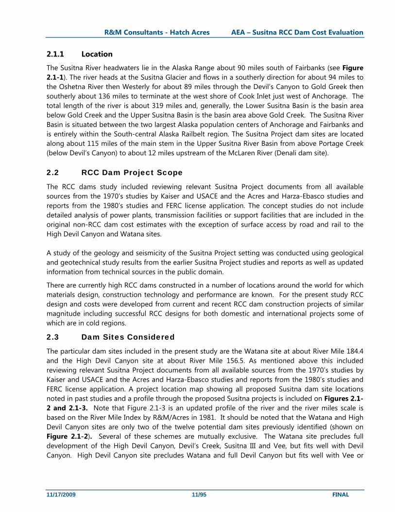
The Hydroelectric potential of the Susitna River has been studied over the past 50-plus years beginning with the U.S. Bureau of Reclamation (USBR) studies in the early 1950s, followed by the U.S Army Corps of Engineers (USACE) studies and review in the 1970’s and studies by Kaiser Engineers in the same time period. The Alaska Power Authority (APA); (now the Alaska Energy Authority or AEA) commissioned comprehensive studies and analyses to determine if hydroelectric development of the Susitna River were viable. Based on those studies, the APA submitted a license application to the Federal Energy Regulatory Commission (FERC) in 1983 for a two dam project on the Susitna River. The project included dams at the Watana site and the Devil Canyon site and was named Watana/Devil Canyon project (FERC preliminary license P-7114). The license application was amended in 1985 for construction of the two dam project but with the Watana dam being constructed in two stages which became known as the Staged Watana/Devil Canyon project estimated to cost $5.9 billion (1985 dollars).
In March 1986 the Susitna project was put on hold by the State of Alaska and the project license surrendered to the FERC.
The Alaska State Legislature, through the FY 2009 capital budget, authorized the AEA to reevaluate the Susitna Project. The authorization included a Railbelt Integrated Resource Plan (RIRP), to evaluate various sources of electrical power to satisfy the long term energy needs for the Railbelt-portion of Alaska.
Initially AEA commissioned review and analysis of the Susitna Project based on updating the costs to December 2008 and reevaluating options for dams at the Devil Canyon site and Watana site using the originally selected earth and rock materials for embankment dam construction.
AEA became aware of the possible advantages of using Roller Compacted Concrete (RCC) in place of earth or rock embankments and commissioned R&M/HAC to study and develop a concept for a Watana RCC dam and expanded the scope to include a RCC dam at the High Devil Canyon site as a single dam alternative to Watana/Devil Canyon and to develop cost estimates for those two dams. RCC technology was in the early stages of development in the early 1980’s and was not considered a viable alternative construction method at the time of the earlier studies, however, RCC technology has now developed to the point of being a viable and cost-effective alternative material to embankment and rockfill for dam construction in many circumstances and has been used for dams in cold regions. Table 2.1-1 presents information on the Watana and High Devil Canyon embankment and RCC dams to provide the reader with relative scale of the embankment and RCC concepts.
For the RCC dam concepts the heavy hauling capability of a railroad to support transport of cement, pozzolans and other materials from sea port to the project site is provided by rail connection along the south access corridor from Gold Creek to Watana and from Gold Creek to High Devil Canyon. Permanent road access to both sites is also provided along the south corridor from the Parks Highway. No road access would be provided from the Denali Highway to the either Watana or High Devil Canyon sites. The present study also includes a review of the project development timeline including precursor confirmation/update studies of environmental factors, sites and FERC licensing.

R&M Consultants - Hatch Acres AEA – Susitna RCC Dam Cost Evaluation
11/17/2009 10/95 FINAL
Confirming studies will be based on the original 1986 reports/study results and include review of those studies and changes in the environmental concerns since that time.
Table 2.1-1 Tabulated Information on Watana and High Devil Canyon Dam Embankment and RCC Concepts
Feature Watana Watana High Devil Canyon
High Devil Canyon
Dam Type Embankment 1)
RCC 4) Embankment 1)
RCC 4)
Dam Structure Volume (cubic yards)
63 million 1)
15 million 4) 48 million 1)
11.6 million 4)
Dam Height (ft)
880 1) 4) 880 1) 4) 855 1) 4) 855 1) 4)
Powerhouse Installed Capacity (MW)
1200
[6x200 Units] 1)
1,200
[6x200 Units] 2)
4)
800 [6x170 Units] 1)
1,200
[6x200 Units] 4)
Annual Generation (GWh)
3,250
[2,670 firm] 1))
3,100 [1,800 firm] 2)
3,400
[2,460 firm] 1)
3,872 3)
Crest Elevation (ft)
2225 1) 2225 1) 1775 1) 1775 1)
Average Tailwater (ft)
1465 1) 1465 1) 1030 1) 1030 1)
Normal Max Pool (ft)
2200 1) 2200 1) 1750 1) 1750 1)
Design Head (ft)
735 1) 735 1) 720 1) 720 1)
Reservoir Area (Acre)
37,800 1) 37,800 1) 24,200 3) 24,200 3)
Reservoir Vol. (Mil. Ac-ft)
9.47
[4.4 live] 1)
9.47
[4.4 live] 1)
5.7 3) 5.7 3)
1) 1982 Acres Feasibility Study 2) 2008 HDR/DTA study 3) 1974 H. Kaiser Study 4) This Study
R&M Consultants - Hatch Acres AEA – Susitna RCC Dam Cost Evaluation
11/17/2009 11/95 FINAL
2.1.1 Location
The Susitna River headwaters lie in the Alaska Range about 90 miles south of Fairbanks (see Figure 2.1-1). The river heads at the Susitna Glacier and flows in a southerly direction for about 94 miles to the Oshetna River then Westerly for about 89 miles through the Devil’s Canyon to Gold Greek then southerly about 136 miles to terminate at the west shore of Cook Inlet just west of Anchorage. The total length of the river is about 319 miles and, generally, the Lower Susitna Basin is the basin area below Gold Creek and the Upper Susitna Basin is the basin area above Gold Creek. The Susitna River Basin is situated between the two largest Alaska population centers of Anchorage and Fairbanks and is entirely within the South-central Alaska Railbelt region. The Susitna Project dam sites are located along about 115 miles of the main stem in the Upper Susitna River Basin from above Portage Creek (below Devil’s Canyon) to about 12 miles upstream of the McLaren River (Denali dam site). 2.2 RCC Dam Project Scope
The RCC dams study included reviewing relevant Susitna Project documents from all available sources from the 1970’s studies by Kaiser and USACE and the Acres and Harza-Ebasco studies and reports from the 1980’s studies and FERC license application. The concept studies do not include detailed analysis of power plants, transmission facilities or support facilities that are included in the original non-RCC dam cost estimates with the exception of surface access by road and rail to the High Devil Canyon and Watana sites. A study of the geology and seismicity of the Susitna Project setting was conducted using geological and geotechnical study results from the earlier Susitna Project studies and reports as well as updated information from technical sources in the public domain.
There are currently high RCC dams constructed in a number of locations around the world for which materials design, construction technology and performance are known. For the present study RCC design and costs were developed from current and recent RCC dam construction projects of similar magnitude including successful RCC designs for both domestic and international projects some of which are in cold regions.
2.3 Dam Sites Considered
The particular dam sites included in the present study are the Watana site at about River Mile 184.4 and the High Devil Canyon site at about River Mile 156.5. As mentioned above this included reviewing relevant Susitna Project documents from all available sources from the 1970’s studies by Kaiser and USACE and the Acres and Harza-Ebasco studies and reports from the 1980’s studies and FERC license application. A project location map showing all proposed Susitna dam site locations noted in past studies and a profile through the proposed Susitna projects is included on Figures 2.1-2 and 2.1-3. Note that Figure 2.1-3 is an updated profile of the river and the river miles scale is based on the River Mile Index by R&M/Acres in 1981. It should be noted that the Watana and High Devil Canyon sites are only two of the twelve potential dam sites previously identified (shown on Figure 2.1-2). Several of these schemes are mutually exclusive. The Watana site precludes full development of the High Devil Canyon, Devil’s Creek, Susitna III and Vee, but fits well with Devil Canyon. High Devil Canyon site precludes Watana and full Devil Canyon but fits well with Vee or
R&M Consultants - Hatch Acres AEA – Susitna RCC Dam Cost Evaluation
11/17/2009 12/95 FINAL
Susitna III. Figure 2.1-3 shows the reservoir scheme for the pairings of Devil Canyon and Watana as well as High Devil Canyon and Vee.
The number of turbines and output at each dam for the present study is assumed to be as established in studies currently being performed by HDR/DTA as reported in the Project Evaluation – Interim Memorandum – FINAL- prepared by HDR/DTA dated March 16, 2009.
Specific project details are: 2.3.1 Watana site, River Mile 184.4.
This alternative comprises construction of a large storage reservoir on the Susitna River at the Watana site with a new RCC dam approximately 850 feet high, and an underground powerhouse containing 6 turbines, with a total installed capacity of 1,200 megawatts (MW). Full pool level (full service level or FSL) is El. 2050 feet. This alternative was originally conceived as an embankment dam in the 1982 Acres Feasibility Study and 1985 Harza Ebasco FERC license amendment (see Figure 2.1-4 and 2.1-5).
2.3.2 High Devil Canyon site, River Mile 156.5.
This alternative comprises construction of a large storage reservoir on the Susitna River at the High Devil Canyon site with a new RCC dam 810 feet high with an underground powerhouse containing 6 turbines modeled on the configuration used at the Watana site with a total installed capacity of 1,200 MW. It should be noted that this concept had an installed capacity of 800 MW in the 1982 Acres Feasibility Study (as did the Watana site). The head is similar to Watana and flow is slightly larger, so we have assumed the same installed capacity as for the updated Watana would be appropriate. This alternative was originally conceived as an embankment dam in the 1974 Kaiser study and 1982 Acres Feasibiliy Study (see Figure 2.1-6 and 2.1-7). The High Devil Canyon alternative would have significant storage for providing power in winter and the reservoir would extend upstream from the Watana site at full pool level (full service level or FSL) of El. 1750 feet.

R&M Consultants - Hatch Acres AEA – Susitna RCC Dam Cost Evaluation
11/17/2009 13/95 FINAL
3. General Setting
3.1 Air Temperature
The following Table 3.1-1 summarizes maximum, minimum and mean monthly temperatures at the Susitna Project site and is taken from the 1983 Acres Feasibility Study. Our review of nearby weather records since 1982 indicates no significant departure from the indicated average temperatures for purposes of the present concept study. From Table 3.1-1 and Figure 3.1-1 it is apparent that, for planning purposes, RCC placement scheduling should be during a 5 month to 5.5 month construction season in which temperatures are suitable for RCC dam construction.
Table 3.1-1 Temperature at the Susitna Project Site (from 1982 Acres Feasibility Study) Max Min Mean Max Min Mean °F °C
January 7.9 -4.8 1.6 -13.4 -20.4 -16.9 February 13.5 -0.4 6.6 -10.3 -18.0 -14.1
March 19.4 3 11.2 -7.0 -16.1 -11.6 April 32.9 14.2 23.5 0.5 -9.9 -4.7 May 45.7 29.1 37.4 7.6 -1.6 3.0 June 58 39.9 49 14.4 4.4 9.4 July 60.2 43.8 52 15.7 6.6 11.1
August 56 41.1 48.6 13.3 5.1 9.2 September 47.1 32.6 39.9 8.4 0.3 4.4
October 30.4 17.5 24 -0.9 -8.1 -4.4 November 15.7 3.7 9.7 -9.1 -15.7 -12.4 December 9.2 -3.4 2.9 -12.7 -19.7 -16.2
The record suitable construction season for RCC is highlighted in gray.
3.2 Hydrology
The hydrology of the Upper Susitna basin was reviewed using stream flow data from the USGS stream gage at Gold Creek located at the lower end of the Upper Susitna basin. This data was then scaled to each dam site of interest based on drainage area to estimate the stream flows at the respective sites.
At the High Devil Canyon site, the scale factor is 0.931 (Kaiser, 1974), and the Watana Dam site was found to have a scale factor of 0.821. The stream flow data in the updated analysis included 54 years of record compared to the 28 years of record available during the original feasibility study by Acres (Acres 1982) and included stream flow records for October 1949 through September 1996, October 2001 through September 2008.
The average annual flow at Watana Dam is estimated as 8,000 cfs with the updated longer flow record, an insignificant increase compared to 7,990 cfs as reported in the 1982 Feasibility Study

R&M Consultants - Hatch Acres AEA – Susitna RCC Dam Cost Evaluation
11/17/2009 14/95 FINAL
(Acres, 1982). The High Devil Canyon average annual flow is estimated as 9,100 cfs. Table 3.1-2 and Figure 3.1-2 show the updated monthly flow statistics for each dam site.
Table 3.1-2 Estimated Monthly Flow Statistics (Oct 1949 – Sep 1996, Oct 2001 – Sep 2008)
Watana Site High Devil Canyon Site
Month Average Flow (cfs)
Minimum Flow on Record
(cfs)
Maximum Flow on Record
(cfs)
Average Flow (cfs) Minimum
Flow on Record (cfs)
Maximum Flow on Record
(cfs) January 1310 595 2013 1486 675 2283February 1164 594 1842 1320 674 2089
March 1064 586 1560 1207 665 1769April 1395 612 3489 1582 694 3956May 11390 3075 22118 12916 3487 25081June 21766 12726 41526 24682 14431 47090July 19639 13144 28242 22270 14905 32026
August 17554 7290 31091 19906 8267 35257September 11291 4181 21765 12804 4741 24681
October 5210 2565 10410 5908 2909 11805November 2215 998 4428 2512 1132 5021December 1563 711 2680 1772 806 3039
3.2.1 Flood Frequency Analysis
A flood frequency analysis using the updated stream flow data, confirmed very similar flow magnitudes and occurrence intervals to those used in the original feasibility study. Figures 3.1-3 and 3.1-4 show the results of the analysis using the USGS Bulletin 17B methodology and HEC-SSP software for the two dam sites.
3.2.2 Inflow Design Flood
The additional years of flow record do not indicate a significant change in annual peak flood frequency. The flood of record occurred on June 7, 1964 with an estimated flow of 70,500 cfs at the Watana Dam site. Therefore, the design inflows remain largely unchanged compared to the 1982 Feasibility Study; Table 3.1-3 presents the results of flood flow analysis.
Table 3.1-3 Flood Flows at Watana and High Devil Canyon Sites
Watana High Devil Canyon
5-year recurrence flow 48,000 cfs 54,000 cfs
Inflow Design Flood (10,000-year recurrence flow)
156,000 cfs 177,000 cfs
Probable Maximum Flood 326,000 cfs 370,000 cfs
R&M Consultants - Hatch Acres AEA – Susitna RCC Dam Cost Evaluation
11/17/2009 15/95 FINAL
3.2.3 Dependable Flows for Power Generation
The updated hydrology analysis shows that the average annual flow has not changed with additional years of streamflow data. The driest year on record was 1969 with an estimated annual flow at the Watana Dam site of 4,500 cfs. However, the two wettest years (calendar years) on record were recorded in 1990 and 2005, when the estimated average annual flows at the Watana Dam site were 10,600 cfs and 10,400 cfs, respectively. Figure 3.1-5 shows the annual average flows at the two dam sites for the period of record. We examined the stream flow record excluding the two wettest years and the driest year and found the average flow changed very little (less than 1%).
3.3 Geologic
The area of study is located within the Coastal Trough Province of south-central Alaska (see Figure 3.3-1 for Regional Geology). The Susitna River is glacier-fed, with headwaters on the southern slope of the Alaska Range. From its proglacial channel in the Alaska Range, the Susitna River passes first through a broad glaciated, intermontane valley of knob and kettle, and braided channel topography. Swinging westward along the edge of the Copper River lowlands, it enters the deep valleys which include the proposed damsites, swinging through the Talkeetna Mountains until it emerges into a broad glacial outwash valley leading to Cook Inlet near Anchorage.
3.3.1 Watana Site
The geology at the Watana site was examined to determine potential issues that would influence design of the RCC dam option. The major sources of information used were the 1982 Feasibility Study (Acres 1982) and 1983 License Application (Harza Ebasco 1983).
Review included: • geology as it affects foundation excavation depth and treatment, • potential borrow areas for sources for material for aggregate production, and • seismicity review and update.
3.3.1.1 Overburden
At the Watana site, overburden thickness on the dam abutments may reach 70 feet or more. Above elevation (El.) 1900 feet, overburden thickness averages 20 feet with local zones to 50 feet on the south abutment. On the north abutment, this thickness reaches 50 to 60 feet. At the upper areas of the abutments, near the top of the slopes, overburden consists of glacial till, alluvium, and talus. Below El. 1900 feet, overburden consists primarily of talus with an average thickness of 10 feet. Subsurface investigations show the contact between the overburden and bedrock to be relatively unweathered.
The river alluvium beneath the embankment dam concept developed in the 1982 Acres Report is up to 140 feet thick, averaging about 80 feet. Subsequent to 1982, drilling and seismic surveys performed in winter from the surface of the ice on the river provided more information about the bedrock surface. Drawings in the 1985 Harza-Ebasco report show that the 140 feet maximum depth of alluvium occurs only at two kettlehole depressions in the bedrock surface. Both of these
R&M Consultants - Hatch Acres AEA – Susitna RCC Dam Cost Evaluation
11/17/2009 16/95 FINAL
depressions are located below the upstream shell of the embankment dam and will not be under the RCC dam. On the proposed axis of the RCC dam, (which is also the axis of the embankment dam) the surface of the river alluvium lies between El. 1458 feet and El. 1462 feet. The lowest point on the bedrock on the axis of the RCC dam is apparently above El. 1350 feet, rising to about El. 1370 feet at the downstream toe of the RCC dam. Thus we have estimated the maximum thickness of alluvium below the RCC dam is approximately 110 feet. See Figure 3.3-2 taken from Fig E.6.2.6v of the 1983 FERC application.
3.3.1.2 Bedrock Lithology
The Watana dam site is underlain primarily by an intrusive dioritic body which varies in composition from granodiorite to quartz diorite to diorite. The texture is massive and the rock is hard, competent, and fresh except within locally developed sheared and altered zones. These rocks have been intruded by mafic and felsic dikes which are generally only a few feet thick. The contacts are healed and competent. The rock immediately downstream and south of the dam site is an andesite porphyry. The nature of the shear zone at the contact between the andesite and the diorite is poorly understood. However, where mapped or drilled, the shear zone is generally weathered and fractured up to 10 to 15 feet below bedrock surface. (See Figure 3.3-3 taken from Plate 9.4 from the 1982 Feasibility Report)
3.3.1.3 Bedrock Structures
Joints
There are two major and two minor joint sets at the Watana site. Joint Set I, which is the most prominent set, strikes 320° and dips to 80° NE to vertical; (See Figure 3.3-4 taken from Figure 5-9 of the Harza-Ebasco report, August 1983).
Shears and Fracture Zones
Several shears, fracture zones, and alteration zones are present at the Watana site. For the most part, the shears and fracture zones are small and discontinuous.
Fracture zones range from 6 inches to 30 feet wide (generally less than 10 feet). These zones are closely spaced joints that are often iron oxide stained and/or carbonate coated. Where exposed, the zones tend to form topographic lows.
Alteration zones are areas where hydrothermal solutions have caused the chemical breakdown of the feldspars and mafic minerals. The degree of alteration encountered is highly variable across the site. These zones are rarely seen in outcrops as they are easily eroded into gullies, but were encountered in all the boreholes. The transition between fresh and altered rock is gradational. The thickness of these zones ranges can be up to 20 feet, but they are usually less than 5 feet thick.
3.3.1.4 Structural Features
As described previously, the Watana site has several significant geologic features consisting of shears and fracture, and alteration zones.
R&M Consultants - Hatch Acres AEA – Susitna RCC Dam Cost Evaluation
11/17/2009 17/95 FINAL
The two most prominent fracture zone areas have been named the "Fins" and the "Fingerbuster." The original feasibility report refers to the Fins and Fingerbuster as: “highly fractured and altered materials within the actual shear zones, which would pose serious problems for conventional tunneling methods and would be unsuitable for founding massive concrete structures. Layouts should be kept within the confines of these bounding zones”. The embankment dam foot print is within the confines of these bounding zones as is the conceptual RCC dam footprint. (See Figure 3.3-3 taken from Plate 9.4 from the 1982 Feasibility Report).
The "Fins" is located on the north bank of the river upstream from the diversion tunnel intake. The area is characterized predominantly by sound, jointed bedrock. The rock mass also contains steeply inclined northwesterly trending zones of closely fractured rock up to 15 to 20 feet wide, 5 to 10 feet wide zones of weak, friable altered rock, and shears which measure one inch to approximately one foot in thickness. These zones have contributed to the erosion of steep gullies, which are separated by intact rock ridges.
The "Fingerbuster" is located downstream from the dam site and is exposed in a 40-foot wide, deep, talus-filled gully just upstream of the andesite porphyry/diorite contact. The rock is moderately close to closely fractured rock with local shears and alteration zones. Slickenslides indicate vertical displacement.
A prominent alteration zone was encountered on the south bank where a drill hole encountered approximately 200 feet of hydrothermally altered rock. Although core recovery in this boring was good, the quality of rock was relatively poor.
3.3.1.5 Groundwater Conditions
The groundwater regime in the bedrock is confined to movement along fractures and joints. In general, the water table is a subdued replica of the surface topography. The groundwater table on the north abutment is generally from 5 to 30 feet below the surface except in areas with steep terrain, i.e. the "Fingerbuster", where it reaches depths of 60 to 90 feet. Numerous icings can be found on both abutments in the winter, particularly on the steep slopes of the south abutment. Groundwater conditions on the south abutment and on the lower north abutment are further complicated because of the existence of permafrost, discussed below.
3.3.1.6 Permafrost Conditions
Permafrost conditions exist on the north-facing slopes and below approximately El. 1750 feet on the north abutment of the dam site area. Measurements indicate that permafrost exists to depths of approximately 120 feet on the south abutment and up to 60 feet on the north abutment. Temperature measurements show the permafrost to be "warm" (within 2° F below freezing).
3.3.1.7 Bedrock Transmissability
Transmissability of water through the bedrock does not vary significantly within the site area, generally ranging between 3.28 x 10⁻⁶ feet/sec to 3.3 x 10⁻⁸ feet/sec.
R&M Consultants - Hatch Acres AEA – Susitna RCC Dam Cost Evaluation
11/17/2009 18/95 FINAL
3.3.1.8 Relict Channel
A relict channel exists north of the Watana dam site. The maximum depth of overburden in the thalweg of the relict channel is approximately 450 feet.
The 1982 Acres Feasibility Report calls for a 10-foot high freeboard dike at this location. Further study could lead to reducing the freeboard requirement because the RCC dam will not require the same amount of freeboard that the embankment dam must have (see Section 4.2), further study of the RCC option could eliminate the need for this dike altogether.
3.3.1.9 Seepage
As a result of construction of the Watana Dam, regardless of dam type, and the impoundment of the reservoir, there will be a tendency for seepage through the foundation rock. The potential for seepage in the foundation of the dam is not high and the bedrock foundations are amenable to grouting.
Buried channels which bypass the dam present the only other potential seepage paths. At the Watana site, the Fog Lakes area is not expected to pose seepage problems because of the low gradient and long travel distance (approximately 4 to 5 miles) from the reservoir to Fog Creek.
During early evaluations, the relict channel north of the Watana site was presumed to pose the greatest potential for seepage through the overburden deposits from the reservoir to Tsusena Creek. Preliminary evaluations also indicated seepage through the buried channel area could result in piping and erosion of materials at the exit point on Tsusena Creek.
A further potential impact could be saturation of the various zones in the buried channel combined with thawing of permafrost in this area. The stratigraphy of the relict channel was defined during 1980, 1982 and 1983 explorations. The results of these explorations indicated that there are no apparent widespread or continuous units within the relict channel that are susceptible to liquefaction. In addition, it appears that multiple periods of glaciation resulted in over-consolidating the overburden deposits within the relict channel, thereby minimizing their potential for liquefaction.
Seepage normally occurring through the foundation rock below the dam will be controlled by two means: the installation of a grout curtain and by a pattern of drain holes drilled from the gallery within the dam. All of the previous studies have assumed the river alluvium will be removed below the dam. This treatment would reduce or prevent seepage as well as controlling uplift pressures in the rock below the dam.
Inspection and drainage galleries will extend through the dam and into the abutments. Should excessive seepage develop during impoundment, it will be possible from these galleries to re-grout to reduce the seepage flow and to drill additional pressure relief drains. Extensive instrumentation of the dam and abutments will be placed during construction for long-term, post-construction monitoring of seepage.
Preliminary assessment of seepage rates through the Watana Relict Channel, assuming conservative permeability rates, indicates that the total seepage quantity is negligible and that there appear to be

R&M Consultants - Hatch Acres AEA – Susitna RCC Dam Cost Evaluation
11/17/2009 19/95 FINAL
no impacts on project operation. Nevertheless, since some uncertainties still exist (in particular, permafrost degradation), remedial measures have been planned to control seepage. First, a drainage gallery would be constructed in overburden across the relatively narrow relict channel exit area at Tsusena Creek. In addition, if required, a positive seepage barrier such as a slurry wall would be built across the throat of the relict channel where the width of unit 'K' (alluvium) is minimal.
3.3.1.10 Permafrost
Thawing of permafrost will primarily affect reservoir slope stability and liquefaction potential. The RCC dam would likely perform better than an embankment dam in the event of a landslide resulting from thawing of permafrost soils that is large enough to generate a surge wave on the reservoir.
Permafrost thawing can also induce settlement of surface facilities constructed in areas of deep overburden north of the Watana dam site, especially where the permafrost is in contact with the reservoir or raised water table, i.e. freeboard dike.
With regard to settlement, it is anticipated that the airstrip, the camps, and other support facilities as well as site roads, will all encounter areas of permafrost. Although the soils in this area are not ice rich, some settlement may occur because of thawing of the permafrost.
Some of the fractures in the rock on the north and south abutments of the Watana dam are ice-filled to depths of approximately 60 and 120 feet respectively. In places, thawing may be necessary prior to grouting of the cutoff.
Some of the likely impacts of permafrost degradation are common to both the embankment dam and the RCC dam options. Thawing of the ground could result in settlement of surface facilities in areas of deep overburden. With adequate structural design, it is possible to mitigate the hazards of settlement in permafrost areas. In the case of the main construction camp, a large pad of granular material will be provided which will evenly distribute the load and insulate the subsoil, hence, retarding thaw rates. Maintenance grading of the airstrip will be necessary to offset the effects of differential settlement.
3.3.1.11 Borrow Sites
A total of seven borrow sites and three quarry sites have been identified for dam construction material delineated as sites A, B, C, D, E, F, H, I, J, and L (see Figure 3.3-5 taken from Harza Ebasco 1983, Figure E.6.2.13). Borrow Sites D and H are considered as potential sources for impervious material (and therefore not of interest for the RCC alternative); Sites C, E, and F for granular material; Sites I and J for pervious gravel; and Quarry Sites A, B, and L for rock fill. Quarry Site A and Borrow Site E are considered as the primary material sites for this project based on the exploration investigations to date. Many of these borrow sites were considered for sources for embankment, core materials and filters and are less applicable to construction of the RCC dam. Sources of concrete aggregate are suggested in the report as Borrow Sites E, C, F and riverbed alluvium; all will require processing. Quarry Site L and Borrow sites C, F, H, and I are considered secondary (back-up) sources of material because of the lengthy haul distance to the dam site, adverse environmental impacts, insufficient quantities, and poor quality material. Due to the lack of bedrock outcrops, Quarry Site B is no longer considered as a viable material site. Borrow Site J would likely not be used
R&M Consultants - Hatch Acres AEA – Susitna RCC Dam Cost Evaluation
11/17/2009 20/95 FINAL
because the water level in the river would be higher due to the damming and diversion of the river, which would not coincide with excavation of borrow material.
The different requirements, volume and properties mean that the optimum quarry areas for RCC aggregate will be different from those investigated for an earthfill dam. The requirements for the aggregate are not very demanding and assessment of investigation results indicate that good aggregate sources on both abutments should be available with 50-70 feet of overburden to be removed.
In summary, estimated reserves of borrow and quarry materials from the primary sources are: • Quarry Site A = 70 to 100 million cubic yards • Borrow Site E = 80 to 90 million cubic yards
3.3.1.12 Geologic Hazards
There are two known major geologic structures that can have an effect on the construction and operation of the power facilities at the Watana site, as mentioned previously. These are the "Fins" feature upstream from the Watana site, and the "Fingerbuster" zone downstream from the Watana site. All of the main project features have been located between the two features, thus avoiding these shear zones.
3.3.2 High Devil Canyon Site
The geology at the High Devil Canyon site was examined to determine potential issues that would influence design of the RCC dam option. The major sources of information used were the 1974 Kaiser Study (Kaiser 1974).
In order to make a preliminary assessment of the technical feasibility of constructing the High Devil Canyon site (River Mile 156.5), a geologic reconnaissance of that site and other areas of interest was made in late June 1974. The prime objectives of this reconnaissance were to identify the type of rock, assess its general condition, and to assess any features of terrain and geologic structure which would affect location, design and construction of the project. In addition, it was necessary to assess the availability of construction materials, and of materials suitable for use as concrete aggregates.
The reconnaissance was made in a fixed wing aircraft for general overall observations supplemented by use of a helicopter to provide access for on-the-ground observations.
3.3.2.1 Topography
The topography at the High Devil Canyon site conforms generally with the one inch to the mile maps prepared by the United States Geological Survey. The canyon is generally V-shaped. The average slope of the north abutment is about 45 degrees for the first 500 feet above the river; above this the slopes flatten to about 25 degrees up to a height of 1,000 feet above the river . The average slope of the south abutment is about 45 degrees for the first 200 feet above the river; above this the slope averages about 25 degrees for the next 800 feet . In the steepest part of the canyon, rock walls on each side rise almost vertically for several hundred feet above the river level. At the higher elevations on both sides of the river the terrain becomes more rounded. While the north abutment of the canyon is covered with dense forest extending to the uplands, the forest on the south abutment
R&M Consultants - Hatch Acres AEA – Susitna RCC Dam Cost Evaluation
11/17/2009 21/95 FINAL
thins several hundred feet above the river to patches and islands of trees, and the uplands have very little tree cover.
3.3.2.2 Geology
Glacial Deposits The site area has been extensively glaciated and is mantled with glacial and non-glacial deposits. The glacial materials consist primarily of moraines and eskers composed of erratic lenses and layers of sand, rounded to angular gravel and cobbles, boulders, silt and considerable rock flour. Some older glacial deposits exhibit considerable weathering evidenced by iron stains and chemical alteration.
Material size ranges from rock flour to boulders three feet in diameter, with a high percentage of material larger than four inches in diameter. Because of the high content of rock flour, and with the exception of occasional granular pockets or stringers of sand, the moraines should be impervious.
Talus and Swamp Deposits
The non-glacial materials are primarily talus, outwash, and swamp deposits. Talus material, unsorted, angular to subangular, occurs generally on the south abutment area and also near the base of gullies and cliffs on both sides of the canyon. It is almost entirely granitic in composition and is derived from adjacent outcrops. The blocks range in size from a few inches to 15 feet in maximum dimension. Deposits on the upper bench areas probably do not exceed 10 feet in thickness; however, on the steep slopes of both abutments they average about 20 feet in thickness and locally may be as much as 40 feet in thickness.
Swamp and muskeg deposits occur on benches on the south abutment in areas of poor drainage. The deposits are composed of moss and low shrubs mixed with fine sand, gravel, and silt. These deposits generally are less than three feet thick and are underlain by moraine and outwash.
River Terraces and Gravel Bars
River-deposited terraces and gravel bars occur several miles upstream of the dam site. They are composed of coarse to fine sand, subrounded to rounded gravel and boulders observed to five feet in diameter. The terrace gravels on the river floor extend to about 60 feet above the river level with an unknown thickness below river level. The rock composition of the materials varies from phyllite to granite to basalt.
Bedrock
The bedrock on the site, as observed in massive outcrops on both sides of the river is a fine-grained granitic rock composed mainly of quartz, feldspar, biotite, and hornblende. Well-developed sets of regional joints occur in the dam site area. The major joint set has a strike that is almost perpendicular to the river channel; it averages about N 25 degrees W but varies from due north to N 45 degrees W. The dip averages 80 degrees east but varies from 65 degrees east to vertical.
Two prominent and well-developed shear or fault zones occur on the north abutment, but are obscured by overburden on the left abutment. These two zones have caused the formation of near-vertical V-shaped gullies; they appear to have a general strike of N 25 degrees W and a dip ranging from 80 degrees NE to vertical. These two fault or shear zones are located upstream of the proposed dam, on the north abutment; on the south abutment they may intersect the proposed diversion

R&M Consultants - Hatch Acres AEA – Susitna RCC Dam Cost Evaluation
11/17/2009 22/95 FINAL
tunnels near their entrances. In that area on the south abutment, however, a diabase-like intrusion is exposed, and it appears that this under-material has deflected the course of the river at this point. From aerial and ground reconnaissance and air photo interpretation there does not appear to be any faulting or rock structure dislocation paralleling the river.
The steep escarpment faces in the river canyon have resulted in large blocks 15 to 20 feet high distinctly separated from adjacent bedrock on the north abutment. No conspicuous faults or displacement features were noted in the south abutment escarpment area adjacent to the river. There appears to be no appreciable depth of weathered rock on either abutment.
The granitic bedrock materials are adjudged to be well suited for the construction of a rockfill dam and would also be suitable for use in the manufacture of concrete aggregates. The occurrence of natural sands and gravels appears to be limited to small river terraces and gravel bars located upstream of the damsite. These deposits are composed of fine to coarse sand, subrounded to rounded gravel and cobbles, and boulder ranging up to five feet in diameter. The rock materials include greywacke, phyllite, granite, and basalt. A terrace deposit ranging in height to 60 feet above river level is located about 3-1/2 miles upstream of the site.
Glacial deposits at elevations ranging upward from the 2,000-foot contour are comprised largely of a silty rock flour with inclusions of generally angular rock fragments. These areas are generally barren except for a thin muskeg cover. The silty rock flour appears to be suitable for use as impervious material and similar glacial till has been used for that purpose in other northern areas. From on-site observations, the exploitation of moderate quantities of impervious materials appears to be economically feasible.
Permafrost may be encountered in access road construction and the exploitation of borrow materials. It will be encountered in transmission line construction.
Reservoir Geology
Aerial reconnaissance supplemented by a study of existing geological data indicates that the reservoir basin will be tight (not prone to significant leakage or having low permeability)at the selected site for High Devil Canyon dam.
North Abutment
The most obvious features of the north abutment of High Devil Canyon dam are the two well-developed shear or fault zones.
The sheared rock is not well healed, and intensive fracturing with open crevices is common. It was not possible to estimate a lateral or vertical displacement in the fault zone. As noted above, fissures 15 to 20 feet deep were observed in the steep escarpment faces near the river.
The upstream toe of the dam is located several hundred feet downstream of the nearest shear zone. While further geologic investigation is required, the occurrence of the shear zones would appear unlikely to affect the stability or performance of an RCC dam.
South Abutment
There is no observable evidence that the two shear zones of the north abutment extend to the south. If these zones do continue on the south abutment, they might intersect the upstream ends of the
R&M Consultants - Hatch Acres AEA – Susitna RCC Dam Cost Evaluation
11/17/2009 23/95 FINAL
diversion tunnels but this occurrence would present no major construction problems. The rock structure of the escarpment face at the river shows no conspicuous faults or displacement features and joint faces are well healed. The diabase intrusion at the bend upstream of the dam is an extremely competent, fine-grained dark grey rock mass; it displays a uniform set of joint planes dipping about 5 to 10 degrees southeast.
This abutment will require more excavation to remove deposits of soft overburden and to remove or spread talus materials. The bedrock appears to be tight, and no particular problems are anticipated in cut-off curtain grouting.
The Riverbed
Due to the depth and velocity of river flow, no observation of riverbed was possible. The depth of boulders and gravel above bedrock may range from 30 to 60 feet.
It will be necessary to excavate to sound bedrock below the dam foundation.
3.4 Seismicity
Generally the Susitna project dams are in Seismic Zone 4. To determine any recent changes in the project seismicity and seismic design parameters for Susitna Project dams, R&M reviewed the Woodward Clyde Consultants report (WCC 1982), which summarized the seismic studies performed for the Susitna Hydroelectric Project between 1980 and 1981, relative to (i) the current understanding of the seismic environment, and (ii) FERC’s state-of-practice for evaluating seismic hazards for hydroelectric projects (e.g. Idriss and Archuleta, 2007). We found that, in general, the seismic hazard determined in the 1980’s studies has not changed but there is a much better understanding of the seismicity of the project area that will benefit design of structures. It should be noted that the M7.9 Denali earthquake originating on the Susitna Glacier fault (November 3, 2002), was within the range identified as a potential earthquake in the 1980’s studies.
The following summarizes our basic findings relative to the deterministic aspects of the seismic hazard (it was beyond our scope and time available to re-evaluate the probabilistic hazard), and preliminary seismic ground motion parameters for use in the conceptual evaluation of an earth embankment, rock fill or RCC dam at the Upper Susitna dam sites.
A. WCC (1982) considered four seismic sources to be ‘active’; defined as faults where there is some evidence of, or are suspected to have, ruptured the surface during the past 100,000 years, including two shallow crustal sources: the Denali fault (right-lateral strike slip mechanism), with a maximum credible earthquake (MCE) of M8, and located about 44 miles north of the project; the Castle Mountain fault (right-lateral strike slip mechanism), with a MCE of M7.5, and located about 66 miles south of the project - and two distinct sources along the Aleutian (Pacific plate – North American plate) subduction zone: the shallow inter-plate (megathrust) zone, with a MCE of M9.2, and located about 40 miles south of the project (see 3.4.A.2); and the deep intra-plate (Wadati-Benioff) zone, with a MCE of M7.5, and passing under the project at a depth of about 31 miles. Additionally, WCC considered the possibility of a random M6 earthquake as the maximum credible event that could occur in the vicinity of the project, without rupturing the surface, which they designated the ‘Detection Level Earthquake’

R&M Consultants - Hatch Acres AEA – Susitna RCC Dam Cost Evaluation
11/17/2009 24/95 FINAL
(DLE). Briefly, this model is still valid relative to the present understanding of the seismic environment in south-central Alaska, with two general exceptions.
1. Based on literature by others, we consider there are two additional seismic sources which meet WCC’s definition of ‘active’, and are close enough to produce notable ground motions at the Upper Susitna dam sites, including: the Susitna Glacier (thrust) fault, with a MCE of about M7.2, located about 40 miles north of the project (this is the fault along which the 2002, M7.9 Denali Earthquake originated (Crone et al., 2004); and the Susitna Seismic Zone, a band of historic earthquakes that do not coincide with any known faults (Ruppert et al., 2008), with a MCE of about M7.4, located about 25 to 30 miles west of the project (Note that WCC recognized this zone, but did not treat it as a distinct active source). And,
2. WCC assumed a great, inter-plate (megathrust) subduction earthquake could rupture to within 40 miles of the Upper Susitna dam sites; however, our evaluation considered a greater distance, about 94 miles, based on the extent of rupture interpreted (by others) during the 1964, M9.2 Great Alaska Earthquake - the limits of a megathrust earthquake used in recent, in-depth studies by others of the seismic hazard in Alaska (Wesson et al., 1999 and 2007) and Anchorage (URS 2008).
B. Based on a review of the Alaska Earthquake Information Center (AEIC) database, there have been at least 10 earthquakes since the WCC seismic studies with ML >5 that occurred within about 125 miles of the Upper Susitna dam sites, including the 2002 Denali Earthquake (M7.9) about 45 miles north of the project, and a M6.5 earthquake in 1992 about 94 miles west of the Watana project and approximately 60 miles west of the HDC site.
C. The most significant difference between the method applied in the WCC studies and current state of practice pertains to the attenuation models used to predict spectral ground motions. Briefly, WCC developed their attenuation models based on works that were published between 1973 and 1980, while we used the attenuation models referenced in the FERC’s state-of-practice for evaluating seismic hazards for hydroelectric projects (e.g. Idriss and Archuleta, 2007), and used in recent, in-depth studies by others of the seismic hazard in Alaska (Wesson et al. 1999 and 2007) and Anchorage (URS 2008).
1. Figure 3.4-1 illustrates the effect of this difference, comparing the mean deterministic response spectra provided in WCC (1982) with the spectra we predicted using attenuation models by Campbell and Bozorgnia (2008), Chiou and Youngs (2008), and Idriss (2008) for the crustal faults; by Atkinson and Boore (2003), Gregor et al. (2002), Youngs et al. (1997), and Zhao et al. (2006) for inter-plate (megathrust) subduction earthquakes; and by Atkinson and Boore (2003), Youngs et al. (1997), and Zhao et al. (2006) for intra-plate (Wadati-Benioff) subduction earthquakes.
2. Table 3.4-1 summarizes the peak horizontal ground accelerations, and Figure 3.4-2 illustrates the 84th percentile deterministic response spectra predicted at the Upper Susitna dam sites for each of the ‘active’ seismic sources described in 3.4.A, using the recent attenuation models cited in 3.4.B.1. Note that all of these attenuation models

R&M Consultants - Hatch Acres AEA – Susitna RCC Dam Cost Evaluation
11/17/2009 25/95 FINAL
predict ground motions for a 5 percent damping ratio. The spectra in Figure 3.4-2 are for a 10 percent damping ratio, which we determined using an average of the correction factors recommended in FEMA (2000), Malhotra (2006), and Newmark and Hall (1982).
Table 3.4-1 - Estimated Peak Horizontal Ground Acceleration (on Rock) Upper Susitna Dam Sites
Earthquake Source (MCE) Peak Horizontal Ground Acceleration, g (WCC
1982) Mean 84th Percentile
Subduction Zone Wadati-Benioff (M7.5)
Megathrust (M9.2) 0.33
0.13 (0.35)a 0.63
0.25 (0.55)a Known Crustal Faults
Denali (M8) Susitna Seismic Zone (M7.4)
0.08 (0.2) 0.08
0.15 0.15
Unknown Local Source, (DLE, M6) @ 3 miles @ 6 miles
0.29 – 0.39 0.17 – 0.25 (0.5)
0.50 – 0.66 0.31 – 0.42
a. WCC assumed the rupture occurs to within 40 miles of the site, we used a distance of 94 miles (see 3.4.A.2. above)
D. WCC (1982) concluded that the maximum credible earthquake that could be expected in the vicinity of the project, without rupturing the surface (the ‘Detection Level Earthquake’, DLE), would produce the strongest (largest) peak and spectral ground motions at the Upper Susitna dam sites. However, WCC’s probabilistic assessment of the seismic hazard indicated that the uniform risk was dominated by shallow inter-plate (megathrust) subduction earthquakes, while the other sources, including the Denali fault and the DLE, only accounted for a minor percentage of the total hazard. Therefore, WCC recommended that design ground-motion criteria (at both the Upper Susitna dam sites) be based on the maximum credible megathrust subduction earthquake, not the DLE.
NOTE: Based on our evaluations, we concur with WCC’s conclusion that the DLE, should it occur close to the project, would produce the strongest ground motions at the Upper Susitna dam sites. Table 3.4-1 and Figure 3.4-3 illustrate the ‘range’ of peak and spectral ground motions that we predicted for a M6 earthquake generated from strike-slip to thrust faulting (with and without surface rupture), occurring within 3 to 6 miles of the site, using the recent attenuation models for crustal sources cited in 3.4.C.1. However, it was beyond our scope and time available to define the characteristics of such a random local earthquake (i.e. distance and fault type). Therefore, further design effort will be required to reconcile the concept, assessment and treatment of the seismic hazard associated with the DLE.
E. As a consequence of (i) considering the rupture area from the maximum characteristic megathrust subduction earthquake to be 94 miles from the project (vs. 40 miles by WCC; see 3.4.A.2), (ii) using the most recent attenuation models (see 3.4.C), and (iii) neglecting at this

R&M Consultants - Hatch Acres AEA – Susitna RCC Dam Cost Evaluation
11/17/2009 26/95 FINAL
time consideration of the DLE (as did WCC), our evaluations indicated that the deterministic ground motions at the Upper Susitna dam sites will be controlled by the maximum characteristic intra-plate (Wadati-Benioff) subduction earthquake; not an inter-plate (megathrust) subduction earthquake as concluded in the WCC studies. Table 3.4-1 and Figure 3.4-4 provide the 84th percentile deterministic peak and spectral ground motions we recommend for conceptual evaluation of a RCC dam at the Upper Susitna dam sites. Note that the vertical motion spectra in Figure 3.4-4 was determined by applying an average of the correction factors recommended in Malhotra (2006), and Newmark and Hall (1982; same as in FEMA, 2000) to the horizontal motion spectra.
3.5 Environmental Setting
The major environmental issues of importance considered in the 1985 license amendment application (APA 1985) for the staged Susitna Project include:
• Project induced change in the seasonal patterns of flow in the river below the dams and the potential for resultant impacts on fish habitat, particularly salmonid spawning and incubation habitat.
• Project induced changes in water quality and temperature below the dams and the potential for resultant impacts to fish (primarily salmonid) populations.
• Potential loss of terrestrial habitat, particularly winter browse habitat for moose, and denning and foraging habitat for bear, due to inundation of lands by the reservoir
• Potential loss of habitat and/or habitat degradation due to construction of project facilities including the construction camp, access road and borrow sites, particularly as it impacts moose, and bear.
• Potential interferences with caribou movement due to project access road and Watana reservoir.
• Potential loss of bald and golden eagle nesting sites through construction activities and/or inundation.
• Potential loss of cultural resources (historic and prehistoric sites and artifacts) due to construction activities and/or inundation.
• Potential socioeconomic impacts to local communities due to the influx of project workers into these communities.
• Potential recreational impacts due to loss of the white water resources of Devil’s Canyon through inundation.
3.6 Land Ownership
The 1985 Application for license amendment (Harza-Ebasco 1985, Volume 1 Exhibit A) included a tabulation of the federal land within the project boundary (see Appendix A, Table of Property

R&M Consultants - Hatch Acres AEA – Susitna RCC Dam Cost Evaluation
11/17/2009 27/95 FINAL
Ownership in the 1980’s). Included in the list of federal lands are both those that had been selected, but not conveyed to non-federal owners and those lands which had been selected by and conveyed to non-federal owners as of 1985.
Subsequent to the 1985 effort, the process of transfer of land from federal ownership to non-federal owners has continued. A review of right of way issues would be required to better describe current land ownership status affecting project facilities and access.

R&M Consultants - Hatch Acres AEA – Susitna RCC Dam Cost Evaluation
11/17/2009 28/95 FINAL
4. Watana Site
This section describes the design for a RCC dam at the Watana site (river mile 184.4) to examine the feasibility to construct a full height RCC dam at the site and as the basis of a cost estimate to be compared to the full height earth embankment dam originally proposed for the Watana site.
4.1 RCC Dam
To realize the scale of the prospective projects it is notable that the full Watana earth embankment dam, at a height of 885 feet, is in the class of highest earthfill dams in the world. Oroville dam on the Feather River, near Oroville, California is an earth-fill dam that rises 754 feet and Nurek dam on the Vakhsh River in Tadjikistan is 1,083 feet high. Roller Compacted Concrete dams have been successfully constructed in cold regions such as the 219-foot high Taishir RCC Dam in Mongolia. It is notable that if constructed today, the full Watana dam would be the highest RCC dam in the world by around 150-feet; the Miel I RCC dam in Columbia is 616 feet high. It is noted that the proposed Bashadam in Pakistan is in the final planning stage and will be 892 feet high when completed and the 710-foot high Longtan Dam on the Hongshui River, China, is scheduled for completion in 2009.
The original Susitna Project design did not consider an RCC dam since the technology was in its infancy at the time of the original study in the early 1980’s. RCC dam technology has advanced significantly to date and is to the stage where confidence in RCC as a dam construction material is high based on actual experience with the techniques of construction and materials. Construction of a dam at the Watana site with RCC has a high potential for construction cost savings vs. the earthfill/rockfill dams originally proposed in at least the following areas:
• Schedule • Reduction in material quantities in the dam • Modifications to the earthfill dam project configuration to realize cost saving in the:
o Spillway o Diversion scheme o Power intakes and conduits o Power house – surface vs. underground
• Potential reduction in construction camp – for example, the construction camp for the original Watana design was sized for around 3600 workers in the original cost estimate.
In order to demonstrate fully the feasibility of the RCC dam option, and thus realize the advantages of the potential costs savings mentioned above, it will be necessary to resolve a number of important questions that are outside the scope of the present assignment. These include:
• Establishing adequate sources and current costs for basic construction materials to be used for the RCC mix.
• Carrying out a thermal analysis of the dam to determine the requirements for cooling the RCC and to determine what maximum rate of RCC placement can be achieved without causing excessive cracking of the RCC.
• Determining the required depth of foundation excavation and the foundation treatment.. • Confirming the feasibility of discharging the design flood by means of a stepped overspill on
the downstream face of the dam.
R&M Consultants - Hatch Acres AEA – Susitna RCC Dam Cost Evaluation
11/17/2009 29/95 FINAL
• Complete recommended analysis necessary to complete the seismicity study for the next stage of RCC dam analysis. This may include identification of appropriate time histories to be used in time history analyses.
• Performing preliminary design of a surface powerhouse with power intake in the RCC dam and surface power conduitss.
Given the unprecedented nature of the project and the limited budget available for determining the feasibility of using RCC to construct Watana dam, the RCC project cost estimate discusses potential issues associated with the dam size, and extrapolates from successful smaller RCC dam designs to develop the configuration of the envisioned RCC project. Further, the cost estimate is based on construction at the original Watana dam site, and on the axis of the original earthfill dam. We have not attempted to optimize the dam axis or project layout to specifically suit the RCC option. It is probable that a complete exploration of all issues associated with a RCC dam of this size, including analysis of alternative alignments and locations, could reduce the cost further.
4.1.1 Dam Configuration Considerations
Our understanding of the design development of a RCC dam is that it will be based on the following considerations:
Crest Elevation - An RCC dam may have a lower crest elevation than an earth fill dam as less flood freeboard is required and, depending on downstream foundation conditions, overtopping for extreme events may be acceptable. In addition, because the RCC dam does not require any provision for the loss of freeboard in an earthquake (seismic slumping) that the earth embankment dam must have, the dam crest may be lower. Furthermore, the settlement of the RCC dam will be less than that of the embankment dam for two reasons: a) the body of the RCC dam is relatively rigid and does not develop post-construction settlement as the embankment dam does; and b) the total mass of the RCC dam is less than that of the embankment dam with the result that it does not develop as much foundation settlement. These considerations could lead to a significant reduction in the required freeboard and therefore a lower crest level for the same full supply level (reservoir elevation) as the embankment dam alternative.
RCC Dam Configuration - RCC dams are designed to the same principles and standards as concrete gravity dams. Design loadings and factors of safety are per FERC guidelines, including; waves and freeboard, earthquake, and silt loads.
Seismic loading is expected to control design: specifically shear stresses at or below RCC-rock interface. Within the dam, tensile and shear strength can be controlled to meet any feasible loading. For a dam of this height, an increase in base length will maximize shear resistance and reduce tensile stresses. Steepening the upper portion of the dam may allow interface shear stress criteria compatibility without increasing mass.
The project configuration General Arrangement Plan and Sections and Details are shown in Figures 4.1-1 through 4.1-3.

R&M Consultants - Hatch Acres AEA – Susitna RCC Dam Cost Evaluation
11/17/2009 30/95 FINAL
4.1.2 Seismic
Part 3.4 of this report summarizes the results of our review of the seismic studies completed for the Susitna Hydroelectric project between 1980 and 1981 (WCC, 1982), and the preliminary seismic ground motion parameters recommended for use in the conceptual evaluation of an RCC dam at the Watana site. Based on that review, and neglecting at this time consideration of a random local earthquake that could occur close to the site on a yet unknown fault (as did WCC), we consider that the deterministic ground motions at the Watana site will be controlled by the maximum characteristic intra-plate (Wadati-Benioff) subduction earthquake, M7.5, occurring at a depth of about 31 miles under the site; i.e. the Maximum Credible Event (MCE); with estimated peak and spectral 84th percentile deterministic peak and spectral accelerations summarized in Table 3.4-1 and Figure 3.4-4, respectively. The specific ground motion parameters used in our preliminary analysis of the RCC dam are discussed below.
4.1.3 Foundations
Foundation conditions and foundation treatment will require examination of suitability for the envisioned RCC dam. This includes curtain grouting (often assumed to have a depth of 50% of the headwater depth of impoundment) and consolidation grouting (depending on the foundation conditions). A drainage curtain downstream of the grout curtain, which will be located near the upstream face of the dam, will be employed to ensure low pore pressures within the concrete and to control uplift pressures in the foundation. Grouting and drainage galleries are included in the body of the dam and will extend into the abutments.
The bedrock profile along the Watana Dam axis is shown on Figure 3.3-4 (Harza-Ebasco 1983). The Section is drawn looking upstream. The bedrock surface in the valley bottom is as follows (from right bank to left bank looking downstream):
Right Abutment: • HD 83-4: Deeply weathered and altered diorite to depth of 25 feet along inclined hole (i.e.
weathered to 17 feet depth) • HD 83-45: Diorite, unweathered, hard, strong
Valley Bottom: • HD 83-10: diorite, fresh, closely to moderately fractured, hard, strong • HD 83-13: Weathered diorite. Depth of weathering is not known because the drill hole only
penetrated the rock for 5 feet • HD 83-44: Diorite and monzonite, unweathered, hard, strong • HD 83-42: Diorite, altered, hard, strong • HD 83-43: Diorite-monzonite, hard, strong for about 10 feet with 10 feet of intensely
fractured altered zone before reaching good rock • HD 83-12: Diorite, altered, chlorite and talc in joints, low strength to the end of hole 10 feet
into bedrock. • HD 83-11: Diorite, little weathering, hard, strong
Left Abutment: • HD 83-46: Diorite, unweathered, hard, strong
R&M Consultants - Hatch Acres AEA – Susitna RCC Dam Cost Evaluation
11/17/2009 31/95 FINAL
From review of the drill holes, the conclusion is that the bedrock surface is expected to have been scoured by glaciation and be generally sound. Hard fractured bedrock under the dam footprint will require consolidation grouting to a depth that will be determined according to the imposed stresses. Initial estimate for consolidation grouting is 65–foot deep holes at 23-foot centers in both directions on the dam footprint In addition, fracture zones and altered zones should be excavated to at least 3 times their width or to 16-foot depth, whichever is the greater, and filled with concrete. It is not necessary to excavate the bedrock unless it cannot be grouted adequately to carry the stresses imposed by the dam.
4.1.4 RCC Dam Design Analysis
A preliminary RCC dam analysis has been carried out using CADAM, a computer program for design and analysis of gravity dam structures. CADAM was developed in the context of research and development activities with guidance from the industrial chair on the Structural Safety of Existing Concrete Dams in Montreal, Canada at Ecole Polytechnique de Montreal.
The CADAM program performs 2D stability analyses on gravity sections. Some of its features are:
• Accepts basic structural dimensions and generates geometry and properties of a section.
• Normal and floodwater levels are input for hydrostatic and uplift calculations.
• Various options are available for uplift distribution (USBR, USACE, FERC).
• Sliding friction parameters for concrete lift joints and rock contact can be specified.
• Earthquake analysis can be carried out with the pseudo-static or pseudo-dynamic approach. The pseudo-dynamic (Chopra’s Method) of analysis was used as required by FERC guidelines.
• Crack “chasing” for static and dynamic loads was included in the analysis.
Three dimensional finite element analysis will be required during future detailed design. The analysis should include dynamic and thermal stress analyses.
4.1.4.1 Basic Information
It is understood that the following details define the conceptual Watana RCC dam at present: • Full supply level (FSL, spillway crest) El. 2185 feet • Dam crest El.= FSL + 5feet (gated spillway)
or FSL +25 feet (ungated spillway) • River bed level El. 1450 feet • Approximate lowest foundation level (RCC dam) El. 1350 feet
4.1.4.2 Dam Alignment
Experience on other RCC dam projects in recent years has found that the optimized embankment dam volume is seldom on the same axis as the optimum RCC dam. Significant reduction in total dam volume could be achieved by modifying the dam axis for the RCC dam, a dam with a much smaller footprint than the original earth embankment dam. For purposes of this study, the original axis has been used for the RCC dam. The axis shown on the figures has been selected based on a limited

R&M Consultants - Hatch Acres AEA – Susitna RCC Dam Cost Evaluation
11/17/2009 32/95 FINAL
examination of the site characteristics and optimization of axis location and alignment will lead to a better solution for the RCC dam location and design.
4.1.4.3 Dam Section
Seismic conditions appear to dominate design, and to address this, the dam configuration concept maximizes the base length to increase the sliding resistance at the critical section. The RCC dam arrangement has two sections; a base section that is envisioned to be constructed quickly in the base of the river channel, and a more conventional RCC dam section above the base. The base would have 1:1 slopes both upstream and downstream to El. 1550 feet. The base section would incorporate the cofferdam and diversion water conveyances. We have considered the base platform to be constructed separately from the upper part of the upper main dam. The principal reasons for this are:
• Because of its dimensions, the base platform has lower and more uniform stress distribution, meaning that less stringent RCC properties are required.
• For approximately half of its depth, the base platform is below river grade and, on the upstream side, will be either backfilled during construction or in the short term by bedload solids deposition cast against the cofferdam.
• Alluvial material may be suitable for aggregate in the RCC of the base platform, that may not be suitable for the high strength RCC that is needed in the remainder of the dam because of the variable nature of the materials.
• The time required to set up the more sophisticated systems for RCC with properties identical to the upper part of the dam (especially the crushing plant) would almost certainly delay the start of dam base RCC production.
4.1.4.4 Galleries
As shown on Figure 4.1-2, five grouting/drainage galleries are initially proposed in the main dam: the lowest gallery will be on top of the base platform at about El. 1550 feet and the top most gallery just below spillway crest at about El. 2140 feet with three intermediate galleries at equally spaced elevations between the top and base galleries. For preliminary planning purposes, galleries are assumed to be 12 feet high by 10 feet wide. This is a simple and practical arrangement; all seepage is drained by gravity, no works are below flood TWLs and no pumping or other power dependent emergency activities are required. Incorporation of a drain near to dam heel may bring significant cost reductions along with operational disadvantages.
In addition, an inspection and instrumentation gallery is proposed in the base section located over the one-third point on the dam base. This gallery will also be 12 feet high by 10 feet wide.
4.1.5 Loading
The following load cases were assumed for the preliminary design and analysis:
Case 1 – Normal
A. Design weight

R&M Consultants - Hatch Acres AEA – Susitna RCC Dam Cost Evaluation
11/17/2009 33/95 FINAL
B. Hydrostatic forces for normal maximum reservoir level of El. 2185 feet
C. Ice – 12 thousand pounds (kips) per linear foot
D. Uplift and seepage forces.
Case 2 – Probable Maximum Flood (PMF)
A. Dead weight
B. Hydrostatic forces for maximum reservoir level of El. 2211.8 feet
C. Uplift and seepage forces.
Case 3 – Post Seismic
A. Dead weight
B. Hydrostatic forces for normal maximum reservoir level of El. 2185 feet and normal tailwater level of El. 1478 feet
C. Ice – 12 kips per linear foot
D. Maximum Credible Earthquake (MCE): Seismic inertial and hydrodynamic forces for MCE with horizontal peak ground acceleration (HPGA) of 0.63 g and vertical peak ground acceleration (VPGA) of 0.42 g. (MCE parameters used in seismic analysis to determine post seismic conditions.)
E. Uplift and seepage forces.
Each of the load cases along with the new procedures related to seismic stability now required by FERC are discussed below (see Table 4.1-1):
Case 1 – Normal is based on hydrostatic loading on the spillway combined with an ice loading applied at the crest of the spillway.
Case 2 – Flood is based on a PMF reservoir level of El. 2211.8 feet. Nappe forces on the overflow sections were not included in the analysis.
Case 3 – Post Seismic: FERC no longer requires that factors of safety during earthquake loading be evaluated. FERC states that due to the “oscillatory nature of earthquakes, and the subsequent structural responses, conventional moment equilibrium and sliding stability criteria are not valid when dynamic and pseudo dynamic methods are used.” FERC’s new Case 3 loading condition looks at the stability consequences of a seismic event. The structure was analyzed under maximum credible seismic conditions to determine the extent of cracking in the base. After the extent of cracking is known, the section is reanalyzed under normal loading (Case 1) to determine the post seismic safety parameters.
The CADAM program performs a pseudo-dynamic analysis based on peak ground acceleration using Chopra’s method. The response spectra for the selected seismic event with 10% damping was used to determine the peak spectral acceleration for the estimated natural period of the dam.
The results are used to determine the length of crack to be used in the post seismic analysis that includes crack lengths and subsequent uplift.

R&M Consultants - Hatch Acres AEA – Susitna RCC Dam Cost Evaluation
11/17/2009 34/95 FINAL
FERC minimum factors of safety for facilities having high or significant hazard potential are as follows for these load cases:
Table 4.1-1 FERC Minimum Factors of Safety against Sliding Failure (FERC Engineering Guidelines Chapter 13)
Case 1 – Normal (Usual)
Case 2 – Flood (Unusual)
Case 3 – Post Seismic (Extreme)
Minimum Sliding Safety Factors
(SSF) 3 2 1.3
CADAM analysis was run for a section of the dam through the middle of the channel with the base of the base platform at El. 1350 feet and the upper section at El. 1550 feet. In summary the analysis criteria were as follows:
• Cohesion at lift joints: 50 ksf
• Friction angle: Concrete / rock foundation and concrete to concrete construction joints assumed phi value of 48 degrees
• Concrete density: 150 pounds per cubic foot (pcf)
• Concrete tensile strength: 33 ksf
• Concrete dynamic tensile strength: 48 thousand pounds per square foot (ksf)
• Uplift pressures: A drain efficiency of 66.7% was assumed in this analysis. Post-seismic uplift is assumed to be a modified uplift pressure distribution that applies full hydrostatic pressure over the length of any crack(s) that may form during the seismic event.
• Load Case 2 – Flood: Nappe weight and forces are not considered downstream of the crest. A tailwater at El. 1491 feet was assumed for PMF.
• Load Case 3 – Post Seismic: Pseudo-dynamic analysis was performed using CADAM in accordance with Chopra’s procedure to determine post seismic conditions. Chopra’s pseudo-dynamic analysis procedure accounts for modal deformations whencalculating accelerations over the dam height. The input used for the dynamic analysis input variables based on the estimated MCE response spectra and the assumed dam geometry are presented in Table 4.1-2.
• Reduction in vertical seismic component: Vertical seismic component reduced to 0.67 of the MCE value since horizontal and vertical seismic accelerations will not occur at the same time.

R&M Consultants - Hatch Acres AEA – Susitna RCC Dam Cost Evaluation
11/17/2009 35/95 FINAL
Table 4.1-2 – Pseudo-dynamic Analysis CADAM Input Variables
Horizontal peak ground acceleration (HPGA) 0.63 g
Vertical peak ground acceleration (VPGA) 0.42 g
Horizontal spectral acceleration (HAS) 0.42 g
Concrete Young’s modulus, (Es) 3,605,000 psi
Foundation Young’s modulus, (Ef) 5,400,000 psi
Dam damping ( ξ 1) 0.05
Foundation damping ( η f) 0.10
Wave reflection coefficient (α ) 0.5
Velocity of pressure waves (C ) 4,720 ft/sec
4.1.6 Results
The Watana RCC Dam preliminary design was based on the CADAM analysis results for a variety of dam geometries. The assumed base with a top at 1550 feet would have upstream and downstream faces unformed and uncompacted; i.e, these face are overbuilt by 1 to 2 feet so that the design section is properly compacted. This requires extra material, but very rapid placement rates can be achieved by avoiding forms. CADAM stability analysis results for the selected load cases are summarized below in Table 4.1-3.
Table 4.1-3 – CADAM Analysis Results Summary
Load Case Sliding Factor of Safety (SSF)
Base Cracking (%)
Case 1 – Normal 3.43 0
Case 2 – Flood 3.20 0
Case 3 – Post Earthquake 2.93 57.7
These results meet FERC guidelines for gravity dams. It is important to note that the stability analysis was found to be sensitive to the seismic parameters, the location of the drainage within the dam, and material properties of the RCC. Small changes in the location of the drainage galleries results in an increase in the external base cracking under seismic loading. The high sliding factors of safety for the “Post Earthquake” case do not represent as conservative a design as may be assumed by the comparison of the analysis results to the FERC required minimum factor of safety. However, it should be noted that optimization of the design will likely lead to reductions in section dimensions and corresponding reductions in dam volumes.
R&M Consultants - Hatch Acres AEA – Susitna RCC Dam Cost Evaluation
11/17/2009 36/95 FINAL
Load Case 3 analysis results show over half the base of the dam would be cracked after a MCE event but that FERC recommended SSF of 1.3 would be met. It is likely that base cracking that may occur during a seismic event would become a “closed crack” post-seismic. Typically an earthquake recovery plan would include an assessment of drain pressures in order to assess any changes in uplift pressures and their effect on sliding stability. Partial cracking of the dam’s base during the MCE is acceptable.
4.1.7 Thermal Stresses
The long-term annual average temperature in the project area is about 32° F (0° C). This is the temperature that the concrete in the dam will eventually cool down to. This is the most important input to thermal stress analyses. The second most important is the coefficient of thermal expansion (Cte) of the concrete, which we know will be close to Cte of the aggregates, therefore it is very important that samples from anticipated aggregate sources be extracted and sent to known labs for analysis of Cte during the final design process.
4.2 Other Engineered Structures
This section describes the analysis elements that went into the development of the conceptual design used in the cost estimate. Given the limited budget and schedule, this should not be considered a thorough or complete exploration of all the issues associated with a dam of this size.
Replacement of one dam design for another affects more than just the dam. Many features of the project general arrangement can be modified to work more efficiently with the RCC dam. These include:
• Cofferdams • Diversion water conveyance • Spillways • Intakes, powerhouse and water conveyances
R&M Consultants - Hatch Acres AEA – Susitna RCC Dam Cost Evaluation
11/17/2009 37/95 FINAL
4.2.1 Cofferdams and Diversion Scheme
The 1982 Acres scheme provided for two 38-foot diameter circular tunnels and an upstream cofferdam designed to operate with a maximum water level of El. 1536 feet at the intake portal. A tunnel diversion is also possible for the RCC dam alternative. However, the smaller footprint of the RCC dam and the lesser consequences of overtopping the unfinished RCC dam during construction than an unfinished earth embankment dam may make diversion water conveyances built within the body of the dam a more convenient and economical choice than the diversion tunnel scheme. The most likely choices for the diversion scheme would be tunnels similar to the 1982 Acres scheme or incorporating the diversion conveyances and upstream cofferdam into the main dam as has been done at several recently constructed RCC dams. We have used the internal diversion for the RCC dam concept for our study in part to better illustrate the internal diversion concept. A more detailed comparison of a tunnel diversion scheme to other options is recommended for further study to determine the diversion scheme most suitable for the project.
The optimization of the diversion water conveyance is contingent on time of closure by pre-cofferdams and time of starting RCC placement for cofferdams constructed in the low flow season. Closure has been assumed to take place in April to allow the RCC cofferdam construction time to advance as far as possible before the summer flood season. It is envisioned that pre-cofferdams will be required for construction of cofferdams and RCC production must be well advanced before starting construction of cofferdams. This is normal in current RCC dam construction practice, but it is important to emphasize schedule constraints as pre-cofferdams will each be relatively large embankment structures each requiring a slurry trench cutoff or jet grouting to bedrock in order to control the flow of water into the excavation for the main cofferdam and the main dam.
As mentioned, the protection level required for an RCC dam is considerably less than for an earth embankment dam. For an RCC dam, the risk period is during the foundation preparation period. Once RCC placement has commenced, damage and delays due to overtopping do not justify a high protection level, such as the 1:50-year flood as proposed (correctly) for the earth embankment dam alternative. A more appropriate flood protection level for an RCC dam alternative would be 1:5-year. The updated hydrology at Watana shows a 1:5-year flood inflow of 48,000 cfs and this flow was used for diversion conduit design.
The invert of the diversion conduits (diversion conveyance) would be located at approximately the level of the existing river bed at both the upstream and downstream ends. Assuming a maximum upstream water level of El. 1550 feet against the main upstream cofferdam, and a diversion conduit invert at the inlet of El. 1460 feet (the assumed upstream bed elevation), two 27-foot diameter pipes would have a capacity of 48,000 cfs including inlet, outlet and friction losses. The tailwater elevation for this magnitude flow was estimated from the river slope, the river cross section, and the estimated bed roughness. It was found to be about El. 1466 feet at 48,000 cfs flow. For that flow with the outlet invert at El. 1450 feet the diversion pipe outlets would be fully submerged and outlet losses would be minimal. The outlet velocity would be about 42 fps, which would require some erosion protection downstream from the outlet.
A potential construction procedure that maintains RCC placement even during flows which exceed the design diversion flood is to construct the dam with a lower crest elevation section in the middle
R&M Consultants - Hatch Acres AEA – Susitna RCC Dam Cost Evaluation
11/17/2009 38/95 FINAL
as shown on Figure 4.2-1. As placement proceeds, flood flows exceeding diversion capacity can pass over the lower section. This is the practice elsewhere in the world on RCC dams and construction continues during floods.
4.2.2 Spillway
4.2.2.1 Selection of Spillway Type
The spillway configuration is expected to change from the embankment dam scheme by eliminating the side channel spillway and emergency spillway and instead incorporating an overflow section into the RCC dam. The spillway design influences the layout and construction of the dam. Two obvious options are possible:
• Ungated • Gated
An ungated spillway has advantages over a gated spillway including: • Community acceptance (no possibility of operator error) • Reduced O&M costs • Reduced peak outflow resulting from attenuation of peaks due to routing of flood through
the reservoir above FSL.
Stepped spillways have been adopted for many RCC dams, where the downstream face is normally constructed in steps. Many hydraulic models have been constructed and compared with prototype performance. There is certainly no prior experience of stepped spillway performance over an 800-foot drop, but we would expect significant dissipation of energy over the course of the fall.
Until such time as the following are developed, it will not be possible to develop an optimum spillway arrangement:
• Confirm inflow floods. • Confirm reservoir elevation-volume relationship. • Confirm flood hydrographs. • Carry out flood routing for ungated spillway arrangement. • Frequency of spillway operation.
4.2.2.2 Selection of Spillway Design Floods
Normal design practice for projects of this magnitude requires the project to be capable of passing the PMF routed through the reservoir without endangering the dam. In addition to this requirement, the project should have sufficient spillway capacity to safely pass a major flood of lesser magnitude than the PMF without damaging the main dam or ancillary structures. The flood frequency analysis presented in Section 3.2, above, produced the values in Table 4.2-1 below.

R&M Consultants - Hatch Acres AEA – Susitna RCC Dam Cost Evaluation
11/17/2009 39/95 FINAL
Table 4.2-1 Spillway Design Flows for Watana
Month US Standard Metric
Average annual flow 8,100 cfs 229 m3/s
Maximum average monthly flow (June) 41,500 cfs 1,175 m3/s
Minimum average monthly flow (March) 590 cfs 17 m3/s
Design flood inflow (1:10,000 year)
156,000 cfs 4,417 m3/s
PMF (probable maximum flood) 326,000 cfs 9,231 m3/s
The spillway was sized for a peak inflow of 156,000 cfs, which is equal to a 1:10,000 year reservoir inflow event. The spillway would be un-gated with the crest at El. 2185.0 feet, corresponding to the normal maximum operating water level (Acres 1982). The spillway would comprise eleven 50-foot wide spill bays and ten 6-foot wide piers for a total spillway length of 610 feet. The piers would support a roadway across the spillway and likely be round-nosed or elliptical and tapered to the downstream edge to facilitate a gradual expansion and more evenly distributed flow over the spillway chute. Figure 4.1-1 shows a plan view of the spillway.
The ungated spillway would be designed for a capacity of 156,000 cfs with a reservoir level of El. 2202 feet, including the flow contraction effects of the piers and abutments. The PMF flow of 326,000 cfs was calculated to result in a water level of up to El. 2211.8 feet, overtopping the dam by up to 2 feet, however this is without taking into account attenuation of outflows due to reservoir storage above FSL. Considering attenuation would likely result in no overtopping occurring.
The spillway chute would be stepped, with step heights and lengths of approximately 15 feet following the design criteria of Chanson (Chanson 2001) to maximize the energy dissipation before the tailrace. The river channel is only approximately 400 feet wide downstream of the dam, necessitating a reduction in the width of the spillway chute from 610 feet at the top to 400 feet near the bottom. The spillway is assumed to be faced with conventional concrete. The residual energy at the bottom of the chute at design flow is approximately 55 feet, reducing the need for an expensive energy dissipater design and instead allowing for a more conventional stilling basin with apron and end sill. Figure 4.1-2 and Figure 4.1-3 shows sections and details of the stepped spillway and the stilling basin.
The spillway design presented herein is conceptual and a hydraulic model study would be required to confirm design of both the stepped spillway and the stilling basin.
4.2.3 Power Intake
Particularly when the powerhouse is a surface powerhouse located at the toe of the dam, the power intake can be incorporated into the body of the dam. There are numerous examples of this. A good example is the 2400 MW Son La Plant in Vietnam. See Figure 4.2-2. Substantial cost savings can be expected to result from the elimination of a separate intake structure and the corresponding reduction in power conduit length.
R&M Consultants - Hatch Acres AEA – Susitna RCC Dam Cost Evaluation
11/17/2009 40/95 FINAL
4.2.4 Powerhouse
An underground powerhouse is a logical choice for the embankment alternative at the Watana site given the inherent risk associated with locating water conveyance near embankment structures. The restricted topography and favorable geological conditions also supported the selection of an underground powerhouse in the south abutment. The competency of the granite bedrock indicates the possibility of excavating an underground chamber and various tunnels with a minimum of support. Deep drilling, of course, would be required to fully outline the problems which may arise during construction of the powerhouse chamber and the various tunnels. With a concrete dam, the powerhouse could be moved to the toe of the dam with intakes and water conveyance integrated into the dam structure. This would eliminate extensive underground works for penstock, surge tanks, powerhouse, transformer gallery, tailrace and access tunnels. This would also eliminate much of the risk associated with subsurface construction; however, the weather would have a greater effect on surface powerhouse construction. The shorter distance between intake and powerhouse may somewhat reduce the total head on the project; however, the shorter water conveyance would reduce the head loss during generation so it would be difficult to estimate if the surface powerhouse would produce more or less power at the site. A surface powerhouse profile from the Son La project is shown on Figure 4.2-2. This is a major reconfiguration of the project that has not been fully explored to date; however, the influence on the total cost of the project is expected to be significant. 4.2.5 Comparison of Material Quantities between Embankment and RCC Concepts
An effective method of observing some fundamental differences between alternative dam designs is to compare some of the major quantity numbers that were used to develop the cost estimate. The quantities were developed to the level of conceptual dam design. Further refinement may have the potential to increase or decrease the material requirements and corresponding costs. The Watana Embankment dam in the 1992 Acres Feasibility Study was estimated to have a volume of the rockfill of 62 million cubic yards. Our study has a volume of the gravity RCC dam estimated at 15 million cubic yards, which is 24.2% of the volume estimated for the embankment dam alternative. When comparing volumes of material it is also important to note that the RCC will be far more homogeneous allowing transport and placement with the same equipment spread. Some variation in the RCC mix may be developed during final design and special procedures will occur were there are interfaces between RCC and conventional concrete as well as at cold joints and structures within the dam such as galleries, spillways and other water conveyances; see Table 4.2-2. Note that this report on an RCC dam option for Watana is based on a structure with the same axis as the embankment dam option. Watana dam has not been looked at from a Gravity-Arch point of view, but it may be worthwhile to explore the viability of this approach due to potential further

R&M Consultants - Hatch Acres AEA – Susitna RCC Dam Cost Evaluation
11/17/2009 41/95 FINAL
savings in the dam structure cost by the further reduction in materials quantities due to the thinner section of the G-A structure.
Table 4.2- 2_ Comparison of selected Quantities Watana Embankment vs. RCC Concept Item Embankment Scheme RCC SchemeCofferdams (CY) 364,100 NA 1)
Main Dam (CY) 61,578,000 15,000,000Foundation Exc. (CY) 11,932,500 3,977,499Surface Prep. (SF) 10,058,000 3,228,618Contact Grouting (LF) 687,000 350,000Grouting Galleries Exc. (CY) 43,000 90,400Spillway Exc.(CY) 2,958,500 13,000Spillway Concrete (CY) 2) 129,800 174,000Spillway Gates (US$) 3) $14,208,000 NA
1) RCC Cofferdam incorporated into main dam (pre cofferdam not included for either scheme) 2) Conventional concrete only (RCC included in main dam quantities) 3) RCC concept uses ungated spillway
R&M Consultants - Hatch Acres AEA – Susitna RCC Dam Cost Evaluation
11/17/2009 42/95 FINAL
5. High Devil Canyon Site
This section describes the project layout associated with an RCC dam at the High Devil Canyon site (at river mile 156.5). This is the basis of a cost estimate to be compared to the full height earth embankment dam originally considered for construction at the High Devil Canyon site as an alternative development to the schemes developed for the license application. Given the limited budget and schedule, this should not be considered a thorough or complete exploration of all the issues associated with a dam of this size.
5.1 RCC Gravity Arch Dam Design Considerations
This section describes the preliminary design efforts for a RCC gravity arch dam at the High Devil Canyon site (HDC).
5.1.1 Layout
The limited information available makes it necessary to ensure that a conservative approach to layout is followed to ensure the legitimacy of the conclusions.
In this case, cross-sections were prepared from the digitized 100’ contour interval surface topography. In order to establish dam foundation levels, the rock surface contours were prepared by assuming that the depth of overburden varies from 30 feet at El. 1800 down to 100 feet at El. 1000 feet. This assumption was based on the conditions at Watana as shown by borehole logs and on the geotechnical observations in the 1974 study (Kaiser 1974). On this basis, with crest El. 1775 feet (for a rockfill structure with gated spillway), the HDC dam would have minimum foundation level of El. 900 feet and a maximum height of 875 feet
Figures 5.1-1 to 5.1-5 shows the preliminary layout of the HDC dam developed on the basis of the above criteria. This layout results in a crest length of approximately 3600 feet measured along the upstream edge of the crest. Only the central 1700 feet are curved, with a radius of 1500 feet. Gravity sections have been adopted for the left and right abutment closure sections.
The preliminary nature of this layout is emphasized, noting that it is based on approximate topography, even more uncertain foundation levels and with no directly determined subsurface information at all from the site therefore subsurface conditions were inferred from .
The preliminary section arrangement to be used for the initial finite element runs was based on the designed cross-section of a similar height dam in South America.
Following initial assessment of the ungated spillway arrangement, the dam crest was set at El. 1770 feet (for FSL of 1750 feet) and the crest width at 30 feet. Figure 5.1-5 shows details.
Subject to stability verification, the section of the gravity arch above El. 1335 is identical to the non-arch gravity section to the abutments (see 5.1.2 following).
Preliminary calculations indicate that this section on the Figure 5.1-3 alignment with the inferred rock surface contours will have an RCC volume of about 11.6 million yd3.
R&M Consultants - Hatch Acres AEA – Susitna RCC Dam Cost Evaluation
11/17/2009 43/95 FINAL
5.1.2 Dam Axis and Section
As distinct from the Watana study, the HDC assessment commenced with the adoption of a gravity-arch section. The gravity-arch (G-A, often referred to as arch-gravity) option combines both arch and gravity action to resist the applied loads.
In simplified terms, whereas a gravity section resists applied loads by its own mass and the shear strength of the concrete-rock foundation interface, the G-A section partially transfers the loads to the abutments. Obviously, for given loading conditions, the thinner the arch section, the greater the strength requirement for both the dam concrete and the abutment supports.
It is not the intent of this report to discuss dam types and design methods in depth. It is noted that EM 1102-2-2201 (USACE 1994), gives a good introduction to arch dam layout and design.
Although both HDC and Watana comply with the USACE basic criterion for consideration of an arch dam (crest length/height preferably <3, but up to 6 acceptable), the long, shallow abutments are not appropriate for a thin arch dam (especially without intensive investigation of abutment properties), but both may well be suitable for G-A design.
Two of the most important dams in the USA are G-A: Hoover and Glen Canyon. The more recent of the two, Glen Canyon (completed in 1965) is the most relevant as far as the Susitna dams are concerned. Glen Canyon has a maximum height of 710 feet, a crest length of 1,560 feet and a constant radius of approximately 900 feet.
Preliminary layouts of HDC as a G-A dam focused on applying a constant radius over the entire length. This approach resulted in either excessively flat radii (>2,000 feet) which will reduce arch action, excessive crest length (25% longer than optimum straight axis) or unfavorable alignment of overflow section relative to river alignment.
5.1.3 Foundations
Foundation conditions and foundation treatment will require examination of suitability for the envisioned RCC dam. This includes curtain grouting (often assumed to have a depth of 50% of the headwater depth of impoundment) and consolidation grouting (depending on the foundation conditions). A drainage curtain downstream of the grout curtain, which will be located near the upstream face of the dam, will be employed to ensure low pore pressures within the concrete and to control uplift pressures in the foundation. Grouting and drainage galleries are included in the body of the dam and will extend into the abutments.
5.1.4 Analysis
The High Devil Canyon Gravity Arch Dam initial concept consists of a gravity arch dam tangentially flanked on each side by straight gravity dam segment abutments. Because the structural behavior of the arrangement is 3D and is not strictly an arch, a general 3D structural analysis is required. A cursory Finite Element Analysis (FEA) was performed on the initial trial layout of the dam. The layout and cross-section of the dam is shown in Figures 5.1-2 and 5.1-3.
The FEA was performed using SAP2000. Only a linear analysis of the dam was performed to obtain a qualitative assessment of the structural performance of the dam. The analysis does not consider
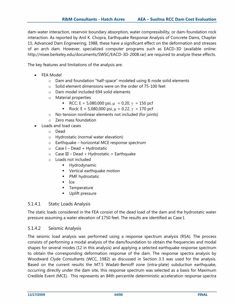
R&M Consultants - Hatch Acres AEA – Susitna RCC Dam Cost Evaluation
11/17/2009 44/95 FINAL
dam-water interaction, reservoir boundary absorption, water compressibility, or dam-foundation rock interaction. As reported by Anil K. Chopra, Earthquake Response Analysis of Concrete Dams, Chapter 15, Advanced Dam Engineering, 1988, these have a significant effect on the deformation and stresses of an arch dam. However, specialized computer programs such as EACD-3D (available online: http://nisee.berkeley.edu/documents/SWSC/EACD-3D-2008.rar) are required to analyze these effects.
The key features and limitations of the analysis are:
• FEA Model o Dam and foundation “half-space” modeled using 8-node solid elements o Solid element dimensions were on the order of 75-100 feet o Dam model included 694 solid elements o Material properties
RCC: E = 5,080,000 psi, μ = 0.20, γ = 150 pcf Rock: E = 5,080,000 psi, μ = 0.22, γ = 170 pcf
o No-tension nonlinear elements not included (for joints) o Zero mass foundation
• Loads and load cases o Dead o Hydrostatic (normal water elevation) o Earthquake – horizontal MCE response spectrum o Case I – Dead + Hydrostatic o Case III – Dead + Hydrostatic + Earthquake o Loads not included
Hydrodynamic Vertical earthquake motion PMF hydrostatic Ice Temperature Uplift pressure
5.1.4.1 Static Loads Analysis
The static loads considered in the FEA consist of the dead load of the dam and the hydrostatic water pressure assuming a water elevation of 1750 feet. The results are identified as Case I.
5.1.4.2 Seismic Analysis
The seismic load analysis was performed using a response spectrum analysis (RSA). The process consists of performing a modal analysis of the dam/foundation to obtain the frequencies and modal shapes for several modes (12 in this analysis) and applying a selected earthquake response spectrum to obtain the corresponding deformation response of the dam. The response spectra analysis by Woodward Clyde Consultants (WCC, 1982) as discussed in Section 3.3 was used for the analysis. Based on the current results the M7.5 Wadati-Benioff zone (intra-plate) subduction earthquake, occurring directly under the dam site, this response spectrum was selected as a basis for Maximum Credible Event (MCE). This represents an 84th percentile deterministic acceleration response spectra

R&M Consultants - Hatch Acres AEA – Susitna RCC Dam Cost Evaluation
11/17/2009 45/95 FINAL
event generating a horizontal peak ground acceleration (HPGA) of 0.46 g. A damping factor of 10% was used in the analysis.
The RSA was performed by applying the response spectrum to the foundation boundary independently in two orthogonal horizontal directions, one in the direction of the valley and one across the valley. The two structural responses were then combined by the root sum squared (RSS) method. The resulting combined response is treated as acting in both a positive and negative direction. The positive and negative responses are added in turn to the combined dead load and hydrostatic load response to obtain an envelope of the overall response, identified as Case III. The two enveloped responses are identified in the analysis as Case III Max for maximum tensile stresses and Case III Min for maximum compressive stresses.
5.1.4.3 Analysis Results
The following tables show the results of the analysis. Table 5.1-1 lists the crest displacements.
Table 5.1-1 Crest displacements (inches)
Case Radial Tangential Vertical Case I -0.76 0.01 -0.42
Case III + 5.82 - 6.56
+ 1.10 - 1.09
+ 0.71 - 1.14
*Negative radial displacement is in the D/S direction
Table 5.1-2 lists the stress range on the U/S and D/S faces for the arch and cantilever loading directions.
For comparison, the following stress criteria are presented. For an extreme load case (MCE) the factor of safety for compressive and tensile stresses are 1.1 and 1.0, respectively, (Table 11-1.1, Chapter 11 - Arch Dams, Engineering Guidelines For The Evaluation Of Hydropower Projects, FERC). Assuming a compressive strength of f’c = 4350 psi, the allowable compressive stress would be fc = 3955 psi.
For tensile stresses, a comparison value is based on the discussion and Figure 15-38 in Earthquake Response Analysis of Concrete Dams, Chapter 15, Advanced Dam Engineering. Here the “apparent” tensile strength under seismic loading is ft = 3.4f’c2/3 = 906 psi.
The apparent tensile strength is not an "allowable" tensile stress value. If predicted tensile stresses are below this value but extend over large areas of the dam, the results are still suspect and the analysis should be re-run to account for redistribution of tensile stresses due to joint and crack opening.

R&M Consultants - Hatch Acres AEA – Susitna RCC Dam Cost Evaluation
11/17/2009 46/95 FINAL
Table 5.1-2 Stresses (psi)
Case Face / Load Direction Stress Approximate Location
Case I Upstream / Arch 109
-336At crest at right abutment. At crest at crown cantilever section.
Upstream / Cantilever -374 Near base at crown cantilever section.
Downstream / Arch 72
-309At crest at right abutment. At crest at crown cantilever section.
Downstream / Cantilever -850At base just upslope left of crown cantilever section.
Case III Max Upstream / Arch 838
691
At base just upslope right of crown cantilever section. At crest at crown cantilever section.
Upstream / Cantilever 1366At base just upslope left of crown cantilever section.
Downstream / Arch 925About 150 feet below crest right of crown cantilever section.
Downstream / Cantilever 874About 240 feet below crest left of crown cantilever section.
Case III Min Upstream / Arch -1340 At crest at crown cantilever section.
Upstream / Cantilever -1922At base just upslope left of crown cantilever section.
Downstream / Arch -1263About 150 feet below crest right of crown cantilever section.
Downstream / Cantilever -2299At base just upslope left of crown cantilever section.
5.1.4.4 Discussion
Under the MCE earthquake loading, the stresses found in the analysis exceed the assumed design stress criteria. Considering the exclusion of the additional interaction effects mentioned above and the vertical component of earthquake motion, it would be expected that a comprehensive analysis of the dam would indicate greater stresses than found in the present analysis. However, it is expected that the initial concept could be refined based on the present analysis results to reduce the stress in the regions of high tensile stress. The refined model could then be analyzed by the more comprehensive methods mentioned above for the final design iteration. The dam appears to be feasible and would merit additional design development if its estimated cost is competitive with the Watana RCC gravity dam.
5.1.4.5 Thermal Stresses
The thermal stress situation is even more important for the G-A case as the structure must remain in compression under all circumstances. The dam will be constructed and will attain maximum internal temperatures in the warmer months and will cool down rapidly during the winter. This cooling will cause contraction that under critical circumstances could produce cracking across the structure.
R&M Consultants - Hatch Acres AEA – Susitna RCC Dam Cost Evaluation
11/17/2009 47/95 FINAL
The keys to controlling this tendency are: • Place RCC at the lowest economically feasible temperature • Keep amount of cement in the RCC to the minimum amount necessary to achieve the target
strength.
Until detailed thermal stress analyses are carried out, the permissible maximum placement temperature cannot be precisely defined, however a value of 50° F (10 °C) can be considered a good starting estimate..
There are many tools available for controlling and reducing the placement temperature of the RCC. The most economical of these is to ensure a low temperature of the aggregate, which makes up at least 75% by weight of the total mix. In Alaska, this result can be achieved by producing aggregate, to the maximum extent possible, during the winter months.
Obviously, there will be a cost penalty associated with crushing and stockpiling aggregates during the winter months, however any such cost will be insignificant compared to the cost (and energy demand) of aggregate cooling during the summer.
In order to keep the cement content to a minimum and still achieve the specified 1-year strengths, it will be necessary to introduce a substantial pozzolanic component into the mix.
5.1.5 Results
The dam layout adopted as a starting point for the HDC gravity-arch option was based on arrangements adopted for relatively similar structures already constructed or designed. The number of sites suitable for G-A dams is not large and the number actually built is even less.
For this reason, there are not a vast number of examples from which to draw experience. At least 3 G-A dams have already been constructed with RCC (two in South Africa and one in China). None of these was over 300 feet high. On the other hand, two of the most important US dams (Hoover and Glen Canyon) are G-A type and are over 700 feet high.
Many other RCC dams are curved in plan, but with relatively large radii and the designers have considered it prudent to not take any arching action into account in distributing stresses within the structures.
When the arching action is considered, 3-dimensional analysis is required. Before the development of finite element analysis (FEA), it was necessary to design G-A (and thin arch) dams using time and labor-intensive manual calculations involving multiple curved beam-cantilever deflection equations.
For preliminary analysis of the proposed dam arrangement, the well-known FEA program, SAP 2000 has been used.
The short-coming of SAP 2000 is that it is a general analysis program and has not been developed to meet the specific and subtle demands of dam designers. Two principal problems for the current application are:

R&M Consultants - Hatch Acres AEA – Susitna RCC Dam Cost Evaluation
11/17/2009 48/95 FINAL
1. SAP 2000 Lacks node generation capability meaning that a coarse block pattern (in this case 100 feet) has to be adopted so that model development does not become excessively time-consuming,
2. SAP 2000 lacks the ability to incorporate zero tension blocks without overly complicating the model and introducing distortions.
The second point is quite important as it means that the contraction joints included at the interface between the gravity abutments and the central G-A portion of the dam cannot be properly modelled. Obviously, tensile stresses cannot be transmitted across these joints and the distribution of tension within the G-A section will be considerably different from that shown in the analysis results. E.g., the tendency for development of high tensile stresses in the upper central part of the dam will be substantially reduced.
The first point means that the distribution of stress within the structure is already quite approximate.
Overall, it can be concluded that SAP 2000 is not the ideal program for advanced analysis of this kind of dam. The results can be described as providing a basis of reference, but by no means definitive results.
For more advanced analysis, the use of more sophisticated FEA programs, such as ANSYS or FENAS will have to be used. Both of these programs also incorporate thermal stress analysis modules.
There is no point in trying to refine the analyses at this stage because of the data shortcomings (especially the very uncertain precision of the foundation contours.
For present purposes, the following recommendations are put forward:
1. Carefully check RCC volume using the section shown on Figure 5.1-3.and foundation contours,
2. In order to account for uncertainties in the analyses, increase total volume for cost estimation by 10%.
Finally, it is emphasized that if the HDC option is to be taken further, the most critical activities will be produce accurate site topography and carrying out sub-surface geotechnical investigation. Only when this information is available will it be possible to commence optimization of the dam layout and details.

R&M Consultants - Hatch Acres AEA – Susitna RCC Dam Cost Evaluation
11/17/2009 49/95 FINAL
5.2 Other Engineered Structures
Many features of the project general arrangement can be modified to work more efficiently with the RCC dam. These include:
• Cofferdams, diversion and construction water conveyance • Spillways • Intake, penstock and surge chamber • Powerhouse and tailrace
5.2.1 Cofferdams and Diversion Scheme
A tunnel diversion is considered the most likely choices for the diversion scheme at HDC similar to the 1982 Acres scheme for Devil Canyon.
Given the higher strength requirements of the gravity-arch RCC dam, incorporating cofferdams constructed under sub-optimal conditions into the main dam structure is likely not practicable. The cofferdams are likely to be relatively large embankment structures each requiring a slurry trench cutoff or jet grouting to bedrock in order to control the flow of water into the excavation for the main cofferdam and the main dam.
The protection level required for an RCC dam is considerably less than for an earth embankment dam. For an RCC dam, the risk period is during the foundation preparation period. Once RCC placement has commenced, damage and delays due to overtopping do not justify a high protection level, such as the 1:50-year flood as proposed (correctly) for the Watana earth embankment dam alternative. A more appropriate flood protection level for an RCC dam alternative would be 1:5-year. The updated hydrology at High Devil Canyon shows a 1:5-year flood inflow of 54,000 cfs and this flow is appropirate for diversion conduit design.
5.2.2 Spillway
As for the Watana RCC option, the ungated stepped spillway has been developed with this initial HDC layout (Figures 5.1-1 through 5.1-5). Table 5.2-1 lists the spillway design flows for the High Devil Canyon site.
For preliminary axis alignment of any concrete dam incorporating the spillway works, the key considerations for selection are:
• Ensuring that the spillway crest is oriented more or less normal to the river alignment downstream of crest so that the discharge is directed into the river in the direction of natural flow.
• Minimizing total volume of concrete in the dam.
• Minimizing adverse slopes (i.e. downhill in the direct of horizontal thrust).
• Based on the proposed 10% increase in flows and floods from Watana to HDC, the principal flow and flood data for HDC would be as follows:

R&M Consultants - Hatch Acres AEA – Susitna RCC Dam Cost Evaluation
11/17/2009 50/95 FINAL
Table 5.2-1 Spillway Design Flows for High Devil Canyon
US Standard Metric
Average annual flow 9,000 cfs 255 m3/s
Maximum average monthly flow (June) 48,580 cfs 1,325 m3/s
Minimum average monthly flow (March) 650 cfs 18 m3/s
Design flood inflow (1:10000 year) 177,000 cfs 5,010 m3/s PMF (probable maximum flood) 370,000 cfs 10,480 m3/s
The spillway would be ungated with the crest at El. 1750.0 feet, corresponding to the normal maximum operating water level (Acres 1982). The spillway would comprise thirteen 50-foot wide spillbays and twelve 6-foot wide piers for a total spillway length of 722 feet. The piers would support a roadway across the spillway and likely be round-nosed or elliptical and tapered to the downstream edge to facilitate a gradual expansion and more evenly distributed flow over the spillway chute. Figure 5.1-2 shows a plan view of the spillway.
The ungated spillway would be designed for a capacity of 177,000 cfs with a reservoir level of El. 1767.4 feet, including the flow contraction effects of the piers and abutments. The PMF inflow of 370,000 cfs would result in a water level of up to El. 1774.4 feet, overtopping the dam by up to 4.4 feet, however this is without taking into account attenuation of outflows due to reservoir storage above FSL. No routing of the PMF has been carried out to date, but it can be anticipated that, given the large area of the reservoir, it will be possible to safely pass the routed PMF outflow without recourse to auxiliary spilling installations and without overtopping of the dam. It may, however, be necessary to increase the height of the dam by 1 or 2 feet.
For these reasons, an upstream water level at El. 1774 feet is adopted for the PMF design case.
The spillway chute would be stepped, with step heights of approximately 28 feet following the design criteria of Chanson (Chanson 2001) to maximize the energy dissipation before the tailrace. The river channel is only approximately 500 feet wide downstream of the dam, necessitating a reduction in the width of the spillway chute from 722 feet at the top to 500 feet near the bottom. The spillway is assumed to be faced with conventional concrete. The residual energy at the bottom of the chute at design flow is approximately 120 feet, reducing the need for an expensive energy dissipater design and instead allowing for a more conventional stilling basin with apron and end sill. Figures 5.1-3 and 5.1-4 show sections and details of the stepped spillway and the stilling basin.
It is important to emphasize that the spillway design presented herein is conceptual and a hydraulic model study would be required to confirm design of both the stepped spillway and the stilling basin. The unit discharge for the proposed HDC spillway is under 270 cfs/ft (25 m3/s/m), well within the range of experience for stepped spillways on RCC dams. The downstream face slope of 0.46H:1V is steeper than most known examples and the height is beyond precedent. As an example, Upper Stillwater in Colorado, one of the most successful stepped spillways in the US, has a downstream slope of 0.6H:1V and a height of just over 200 feet.

R&M Consultants - Hatch Acres AEA – Susitna RCC Dam Cost Evaluation
11/17/2009 51/95 FINAL
Despite the above, there is no hydraulic reason to question the proposed design, particularly when the proposed 28-foot step height is taken into consideration (compared to the usual values of 3 to 4 feet).
5.2.3 Power Intake
Particularly when the powerhouse is located at the toe of the dam, the power intake can be incorporated in the body of the dam. There are numerous examples of this arrangement. A good example is the 2400 MW Son La plant in Vietnam. See Figure 4.2-2. Substantial cost savings can be expected to result from the elimination of a separate intake structure and the corresponding reduction in power conduit length.
5.2.4 Powerhouse
As with Watana, the risk associated with locating water conveyance near embankment structures and the restricted topography and favorable geological conditions led to selection of an underground powerhouse in an abutment of the Dam for the original HDC concept proposed by Kaiser in 1974. Little is know about rock condition at the HDC site and a complete geotechnical program is required to fully define the site geologic conditions to identify problems which may arise during construction of the powerhouse chamber and the various tunnels.
With a RCC dam, the powerhouse could be moved to the toe of the dam with intakes and power conduits integrated into the dam structure. This would eliminate extensive underground works for penstock, surge tanks, powerhouse, transformer gallery, tailrace and access tunnels.
The shorter distance between intake and powerhouse may somewhat reduce the total head on the project, however the short water conveyance would reduce the head loss during generation. A surface powerhouse scheme concept for High Devil Canyon is shown on Figure 5.2-1. This is a major reconfiguration of the project that has not been fully explored to date, however the influence on the total cost of the project is expected to be significant. Please note that the cost estimate in this report has assumed an underground powerhouse with associated underground works as originally proposed.
5.2.5 Comparison of Material Quantities between Embankment and RCC Concepts
The High Devil Canyon site has been developed to some degree, however very little information is available detailing the effort. The best information we have found on the layout of the project is shown on Figure 2.1-6 and in Section 8 of the 1992 Acres Feasibility Study. The volume of the rockfill in the 1982 Acres Feasibility Study is described as 48 million cubic yards. Our study has a volume of the gravity arch dam estimated at 11.6 million cubic yards, which is 24.2% of the volume estimated for embankment dam alternative.
R&M Consultants - Hatch Acres AEA – Susitna RCC Dam Cost Evaluation
11/17/2009 52/95 FINAL
6. Roller Compacted Concrete
6.1 Technology (advantages and limitations of the material)
Roller Compacted Concrete (RCC) is a well established material that has been used successfully for dam construction since the 1980’s. The American Concrete Institute, Subcommittee 207.5 (ACI 207.5R) defines RCC as “Concrete compacted by roller compaction; concrete that in its unhardened state will support a roller while being compacted.” RCC has the same ingredients as conventional concrete which is comprised of cement, water and aggregates. As opposed to the wetter mixtures found in conventional concrete that promotes flow of the mix into structures requiring form work, RCC is a much drier mix and can be placed and compacted in place in less time than conventional concrete by use of conveyors and earth-moving equipment, spread by bulldozers, and compacted by vibratory rollers. When a RCC layer is placed, it can immediately support the earth-moving equipment to place the next layer.
At the Susitna sites the RCC material will have advantages over the embankment dam materials previously considered for the Watana and High Devil Canyon sites and some limitations. Advantages:
• Low cost for Roller Compacted Concrete – in place cost quite small compared to conventional concrete.
• Well suited to dam construction. • Less than half the volume in RCC dam than in embankment dam – less equipment and labor
required for placement. • Lower volume may allow dam completion in less time – reduce construction schedule. • Smaller footprint – less clearing and excavation. • RCC dams can allow overtopping during construction saving substantial construction time
and cost on diversion structures. • Locate spillway on dam. • Intake and powerhouse located at toe of dam. • Low temperatures of aggregate would reduce cooling costs. • Provides opportunity for development of industry in Alaska for cement and pozzolans.
Limitations:
• Cost dependent on location of source of cement and pozzolans (imported materials dependent on world demand).
• No currently developed sources in Alaska of Cement, flyash or pozzolan. • Transportation of large volume of material if no local source developed could burden
infrastructure. • Placement of material is not possible in severe weather conditions.
6.2 Discussion of other Dam Technologies – Watana site
The choice of dam type was examined in several of the previous Susitna Project studies. The 1975/79 USACE, 1974 Kaiser, 1982 Acres and 1985 Harza/Ebasco studies concluded that a central impervious

R&M Consultants - Hatch Acres AEA – Susitna RCC Dam Cost Evaluation
11/17/2009 53/95 FINAL
core embankment dam was the appropriate choice at the Watana site, however advances in dam construction technology since the 1980’s may provide opportunities to employ other dam technologies cost effectively besides the RCC dam subject of this study.
This is a very large dam and any alterative should be considered only if there are precedent projects of near comparable size. Alternative technologies that could be examined include:
• Concrete arch • RCC gravity arch – probably best option • Concrete faced rockfill dam • Asphalt core embankment dam
6.2.1 Concrete arch
The 1982 Acres report compared an embankment dam to a concrete arch at this site. An arrangement for the arch dam is included as Figure 6.2-1. The 1982 analysis indicated the cost of the embankment option was somewhat lower than the arch option. The basic geometry of the site is such that a thin arch is unlikely to be the optimal choice; however a gravity arch is worth considering.
Changes in construction technology since the 1982 study would tend to favor present costs for embankment dam construction over concrete arch dam construction because of cost reductions in large earth moving operations using modern larger mining equipment that would increase efficiencies of the embankment placement.
6.2.2 RCC gravity arch
The topography lends itself to the introduction of some upstream curvature in the RCC gravity dam option. Increasing the curvature opens up the possibility of developing a gravity arch arrangement, along the lines of, e.g., Glen Canyon dam and Hoover dam.
This option would combine the advantages of RCC construction with the reduction in volume of RCC associated with the gravity arch design concept. This concept could be well suited to the conditions at the Watana site and has the potential to be the preferred dam type for the Watana site.
6.2.3 Concrete Faced Rockfill dam
The concrete-faced rockfill dam (CFRD) may have advantages over the earth-core rockfill dam. The CFRD is considered to have high safety performance characteristics, especially resistance to failure with earthquake shaking. It is appropriate for use for very high dams. Crest settlements are relatively low, and decrease in rate rapidly after the first few years. The drainage characteristics of the CFRD and inherent stability of the material would also allow consideration of having a steeper upstream slope than the embankment dam, thereby reducing the total volume of material required. Further evaluation may have value.
6.2.4 Asphaltic Concrete Core Embankment Dam
Asphaltic concrete central core dams have been in use since 1962. Compared with impervious earth core, the placement of asphaltic concrete is less influenced by bad weather conditions. This enables the contractor to extend the working season and conduct an almost continuous operation, keeping

R&M Consultants - Hatch Acres AEA – Susitna RCC Dam Cost Evaluation
11/17/2009 54/95 FINAL
the construction on schedule. Experience from Norway, which is somewhat comparable to the conditions at the Upper Susitna sites, have found that the construction season is approximately one month per year longer than for impervious embankment core placement.
Challenges associated with asphaltic concrete core dams are limited experience with this dam type within the United States and no precedents for a dam of this height. This dam type is not recommended for further consideration for this project.
6.3 Materials Specifics
The RCC mix will be developed based on the availability of materials and how appropriate they are for the climatic conditions. The mix design is based on the standard high cementitious (cement plus supplementary cementitious materials, such as fly ash or natural pozzolans) approach which requires that each horizontal lift surface be covered by the subsequent RCC layer prior to the initial set of the placed material. For a dam the size of Watana or HDC, the initial set will have to be delayed to not less than 24 hours, i.e., the mix will be highly retarded. The type and dosage of set retardant will be determined by trial mixes, however the dosage of retardant will likely not be less than 1% (measured as % of total cementitious material).
The critical parameter for RCC dams, especially when seismic loading is significant, is the direct tensile strength across the horizontal lift joint. All other parameters and requirements devolve from this. The compressive strength (sc), which is easy and cheap to measure, is often used as a proxy for direct tensile strength (st) across the lift joint. For the G-A dam option, the lateral strain (parallel to the dam axis) becomes equally important.
6.3.1 Watana RCC Mix
We estimate that the principal mix criterion for Watana dam should be a target of 230 psi (1.6 MPa) direct tensile strength across lift joints at an age of 365 days. This in turn, indicates a 365 day compressive strength of around 3,600 psi (25 MPa). Table 6.3-1 shows the preliminary mix design for the Watana RCC option. There are a number of assumptions in Table 6.3-1, but it is sufficiently accurate to make an order of magnitude estimate of materials quantities in combination with the volume. Applying the proportions given in Table 6.3-1 to the estimated quantity of RCC (approximately 15 million cubic yards) for the dam, it is estimated that the following quantities of principal materials will be required, measured in short tons:
• 26,307,000 tons of processed aggregate • 877,900 tons cement (type 1 acceptable if no thermal problems) • 1,643,400 tons supplementary cementitious material – most likely fly ash but if a source can
be developed also pozzolans.
These quantities relate only to the RCC dam. Additional quantities of aggregate and cement will be required for other components of the project not changed from the original design in this conceptual study.

R&M Consultants - Hatch Acres AEA – Susitna RCC Dam Cost Evaluation
11/17/2009 55/95 FINAL
Table 6.3-1 – Preliminary Watana RCC Mix Design
Ingredients Mix (%)
by weight SSD Mix
prop SSD Mix
prop Specific gravity Volume Volume
(lb/cy) (kg/m3) (ft3) (cy) Fly Ash 5.41% 219.1 130 2.5 1.404 0.052 Cement 2.89% 117.1 70 3.15 0.596 0.022 Retarder (1% of CM) 0.08% 3.36 2 1.1 0.049 0.002 Water 5.05% 202.3 120 1 3.277 0.121 Air 0.00% 0 0 0 0.000 0.000 Subtotal 13.43% 542.86 322 5.326 0.197 Aggregate 50-20 mm 27.7% 1121.85 672 2.65 6.784 0.252 20-10 mm 17.7% 716.85 429.6 2.65 4.335 0.162 10-5 mm 13.8% 558.9 333.6 2.65 3.380 0.125 5-0mm 27.4% 1109.7 664.8 2.5 7.113 0.264 Subtotal 86.6% 3507.3 2100 21.613 0.803
TOTAL 100.00% 4050.36 2422 26.939 1.00
6.3.2 High Devil Canyon RCC Mix
The mix will be developed based on the availability of materials and how appropriate they are for the climatic conditions. The mix design is based on the standard high cementitious (cement plus supplementary cementitious materials, such as fly ash or natural pozzolans) approach which requires that each horizontal lift surface be covered by the subsequent RCC layer prior to the initial set of the placed material. For a dam the size of HDC, the initial set will have to be delayed to not less than 24 hours, i.e., the mix will be highly retarded. The type and dosage of set retarder will be determined by trial mixes, however the retarder dosage will likely not be less than 1% (measured as % of total cementitious material).
The critical parameter for RCC gravity dams, especially when seismic loading is significant, is the direct tensile strength across the horizontal lift joint. All other parameters and requirements devolve from this. The compressive strength (sc), which is easy and cheap to measure, is often used as a proxy for direct tensile strength (st) across the lift joint. For the G-A dam option, the lateral strain (parallel to the dam axis) becomes equally important.
We estimate that the principal mix criterion for HDC dam should be a target of 290 psi (2 MPa) direct tensile strength across lift joints at an age of 365 days. This in turn, indicates a 365 day compressive strength of around 4300 psi (30 MPa). Based on experience with similar materials and strength RCC the following basic mix (Table 6.3-2) is proposed. Values are based on the theoretical air-free density (TAFD)

R&M Consultants - Hatch Acres AEA – Susitna RCC Dam Cost Evaluation
11/17/2009 56/95 FINAL
Table 6.3-2 – Preliminary High Devil Canyon RCC Mix Design
Ingredients Mix (%) – by weight
SSD Mix prop
SSD Mix prop
Specific gravity Volume Volume
(lb/cy) (kg/m3) (ft3) (cy) Fly Ash 6.02% 244.4 145.00 2.50 1.57 0.058 Cement 3.12% 126.4 75.00 3.15 0.64 0.024 Retarder (1% of CM) 0.09% 3.7 2.20 1.10 0.05 0.002 Water 5.14% 208.7 123.80 1.00 3.34 0.124 Air 0.00% 0.0 0.00 0.00 0.00 0.000 Subtotal 14.37% 583.2 346.0 5.605 0.208 Aggregate 50-20 mm 25.90% 1051.0 623.5 2.65 6.35 0.235 20-10 mm 16.48% 668.8 396.8 2.65 4.04 0.150 10-5 mm 12.84% 521.1 309.2 2.65 3.15 0.117 5-0mm 30.40% 1233.4 731.7 2.50 7.86 0.291 Subtotal 85.63% 3474.3 2061.2 21.4 0.8
TOTAL 100.00% 4057.48 2407.21 27.02 1.00
There are a number of assumptions in the above Table, but it is sufficiently accurate to make an order of magnitude estimate of materials quantities in combination with the volume. Applying the proportions given in Table 6.3-2 to the estimated quantity of RCC in the dam (Approximately 11.6 million yd3 it is estimated that the following quantities of principal materials will be required, measured in short tons (and with an allowance of 10% for waste):
• 19,978,000 tons of processed aggregate • 728,000 tons cement (type II preferred) • 1,404,000 tons supplementary cementitious material (SCM) – most likely fly ash but if a
source can be developed also pozzolans (see Section 7.1.3).
These quantities relate only to the RCC dam. Additional quantities of aggregate and cement will be required for other components of the project not changed from the original design in this conceptual study.
6.3.3 Aggregate
The aggregate processing operation for Watana and High Devil Canyon RCC dams are essentially the same, the difference being the volume of Watana is greater than HDC; aggregate processing will be discussed in detail for Watana only. The total aggregate demand for the Watana dam is about 26 million tons (23.6 million tonnes). In order to ensure shape and ultimate strength requirements, the crushing plant can be assumed to have four stages of processing including a jaw crusher stage,, two cone crusher stages and, one Vertical Shaft Impact crusher stage.

R&M Consultants - Hatch Acres AEA – Susitna RCC Dam Cost Evaluation
11/17/2009 57/95 FINAL
Assuming that the base platform is constructed using alluvial material, the mass of aggregates to be processed from quarry rock is reduced to about 22.5 million tons. Assuming that aggregate production starts 12 months prior to the start of RCC placement, average monthly production of about 232,000 tons will be necessary. Therefore, two 500 tons/hr crushing systems per abutment will be required. Note that “crushing system” means a plant designed to produce the required amount with the required gradation and shape of aggregate, including any necessary recirculation of product.
The mix design indicates that the RCC will contain approximately 25% sand (5 mm to 0mm) by volume of RCC in place (no air entrainment). The volume of RCC required at Watana is approximately 15 million cy. Thus the RCC requires 3.75 million cy of sand.
The only large source of sand for fine aggregates that has been identified is the Susitna River alluvium. The Winter 1983 Geotechnical Exploration Program (Harza-Ebasco 1983) shows that the alluvium in the vicinity of Watana Dam site contains 38% sand (5 mm to 0 mm) overall, and 55% of the alluvium is coarser than 4.75 mm (i.e. gravel size). The portion of the riverbed to be excavated for dam construction would not be sufficient to produce the required volume of sand, so a significant volume of sand will need to be developed by processing quarried rock.
The availability of materials was not previously studied for the High Devil Canyon site, so further geotechnical investigations are recommended if the project is to be further investigated.
6.4 Construction Considerations
This section examines issues associated with the RCC dam construction including assumptions of how material is transported to the RCC dam, mix placement rates, and length of construction season.
The issues associated with construction materials will affect both dam design and the cost estimate: • Environmental conditions, rainfall work stoppage and change in properties, cold weather
considerations, construction season due to temperature, material properties, and the optimum construction period rate of RCC placement
• Source and transportation of construction materials to dam site. • Transportation of concrete to the dam by conveyor. • Techniques for spreading and compacting and creation of; horizontal joints, vertical joints,
contraction joint spacing, forming joints in RCC, sealing of contraction joints, curing, and constructing galleries.
6.4.1 Cooling Concrete During Construction
The long-term annual average temperature in the project area is understood to be near freezing and the groundwater at the dam site is about 34 to 35°F; based on this information, groundwater will likely be used to supply mix water for the RCC and cooling water for the curing of the RCC.
6.4.2 Process Plant Staging
Table 6.4-1 attempts to relate historical performance with required RCC production. This assessment is considered to be quite conservative and it may well be possible to construct the dam in four seasons, but we have conservatively assumed 5 seasons will be required.
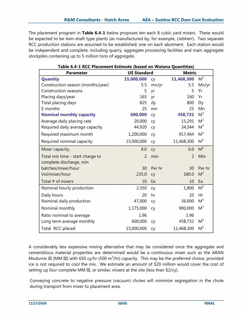
R&M Consultants - Hatch Acres AEA – Susitna RCC Dam Cost Evaluation
11/17/2009 58/95 FINAL
The placement program in Table 6.4-1 below proposes ten each 8 cubic yard mixers. These would be expected to be twin-shaft type plants (as manufactured by, for example, Liebherr). Two separate RCC production stations are assumed to be established; one on each abutment. Each station would be independent and complete, including quarry, aggregate processing facilities and main aggregate stockpiles containing up to 5 million tons of aggregate.
Table 6.4-1 RCC Placement Estimate (based on Watana Quantities) Parameter US Standard Metric
Quantity 15,000,000 cy 11,468,300 M3 Construction season (months/year) 5.5 mn/yr 5.5 Mn/yr Construction seasons 5 yr 5 Yr Placing days/year 165 yr 160 Yr Total placing days 825 dy 800 Dy Σ months 25 mn 25 Mn Nominal monthly capacity 600,000 cy 458,732 M3 Average daily placing rate 20,000 cy 15,291 M3 Required daily average capacity 44,920 cy 34,344 M3
Required maximum month 1,200,000 cy 917,464 M3
Required nominal capacity 15,000,000 cy 11,468,300 M3
Mixer capacity, 8.0 cy 6.0 M3
Total mix time - start charge to complete discharge, min
2 min 2 Min
batches/mixer/hour 30 Per hr 30 Per hr Vol/mixer/hour 235.0 cy 180.0 M3
Total # of mixers 10 Ea 10 Ea Nominal hourly production 2,350 cy 1,800 M3
Daily hours 20 hr 20 Hr Nominal daily production 47,000 cy 36,000 M3
Nominal monthly 1,175,000 cy 900,000 M3
Ratio nominal to average 1.96 1.96 Long term average monthly 600,000 cy 458,732 M3
Total RCC placed 15,000,000 cy 11,468,300 M3
A considerably less expensive mixing alternative that may be considered once the aggregate and cementitious material properties are determined would be a continuous mixer such as the ARAN Modumix III (MM III) with 650 cy/hr (500 m3/hr) capacity. This may be the preferred choice, provided ice is not required to cool the mix. We estimate an amount of $20 million would cover the cost of setting up four complete MM III, or similar, mixers at the site (less than $2/cy).
Conveying concrete to negative pressure (vacuum) chutes will minimize segregation in the chute during transport from mixer to placement area.

R&M Consultants - Hatch Acres AEA – Susitna RCC Dam Cost Evaluation
11/17/2009 59/95 FINAL
A high placement rate will require consideration of an RCC cooling system. Cooling of RCC lifts is possible using suitable PVC tube grids with chilled water circulated to control temperatures due to heat of hydration in the RCC mix (local groundwater temperature is estimated to be around 33º to 34º F).
6.4.3 Weather and Construction Season
Table 3.1-1 shows the temperature levels recorded at the site. The following weather related issues have been considered for planning purposes:
• Tunneling (for diversion works and abutment grouting/drainage galleries) can proceed at any time of the year. Excavation and foundation preparation work should be able to be carried out for at least 9 months of the year.
• Aggregate production for RCC should be possible for 12 months of the year, with reduced efficiency in mid-winter. Emphasis would need to be placed on winter production of aggregate to ensure low temperatures in the stockpiles used for summer production.
• Aggregate stockpile temperatures – with careful management, it may be possible to maintain cold temperatures in the stockpile and avoid expensive forced cooling (ice, wet belts, etc.).
• RCC Placement can occur at temperatures at or near 32ºF (0º C) with 23ºF (-5º C) lower limit so placement should be based on a 5 to 5.5 month construction season.
6.5 Schedule
The Kaiser report-included a schedule for construction of the High Devil Canyon embankment dam project that showed a 6.5-year schedule for dam construction. The RCC option has been estimated assuming a 5.5-year schedule though there is a high probability that 4.5 years is achievable. The start of the diversion and site preparation for both schemes is in the initial 12 to 18 months of the dam construction schedule.

R&M Consultants - Hatch Acres AEA – Susitna RCC Dam Cost Evaluation
11/17/2009 60/95 FINAL
7. Construction Costs
The Cost estimate study comprised: • Establishment of cost for Susitna Project Watana and High Devil Canyon RCC options • Review of cost supporting basic construction costs; including transportation, transmission and
camp facilities • Review of cost estimate background data to consider differences in construction techniques
to see if original estimate is appropriate for current construction methods • Examine the Harza Ebasco Joint venture cost estimate for staged Watana and develop
comparable costs to those used in the HDR/DTA cost estimate
7.1 Upper Susitna RCC Dam Costs
There are many elements that would influence the cost of construction of the Susitna Project RCC dams. The most influential elements are the unit price for RCC and the volume required to construct the dam. There are no directly comparable domestic projects to either the envisioned Watana or High Devil Canyon RCC dam. The most recently completed domestic large RCC dam project is the Olivenhain Dam near Escondido, CA which has approximately one-tenth the volume of the envisioned Watana RCC dam. Even though the Olivenhain dam is much smaller than the Susitna Project dams, the use of US contractors and the availability of cost data and information from the Olivenhain site makes the cost comparison valuable for establishing the unit cost for RCC at the Susitna sites.
7.1.1 Comparison to the Olivenhain Project
Construction on the Olivenhain Dam began in the fall of 2000 and was completed in 2002. Cost information provided by the Portland Cement Association (PCA) indicates the cost per cubic yard of concrete for the RCC dam was $54.43 per cubic yard. This cost includes the cost of materials delivered to the site and the cost of handling which comprised mixing, transporting, spreading, compacting and curing. Figure 7.1-1 shows the long-term cost trend data for RCC dams from the PCA that relates the volume of RCC used in the project plotted against cost per cubic yard. From this figure it can be seen that the Olivenhain Dam’s RCC unit cost is significantly higher than the long-term trend. The reason for this can be better understood by analyzing factors specific to Olivenhain. Cost factors compared include: cost of aggregate production, climatic factors, materials logistics, RCC mix design, and construction wage rates.
Aggregate Production - All aggregate at Olivenhain was quarried and processed from hard granite at the project site using crushers to achieve the material gradations required for RCC production. To ensure a constant source of power for the crushers and other equipment, Kiewit Pacific Co., the general contractor, utilized onsite generators for all electric power requirements. The added equipment, maintenance and fuel costs associated with on site power generation was a significant cost factor for the project. The remoteness of the Susitna Project dams will require a similar arrangement unless transmission facilities are constructed early and power from the Railbelt grid is provided.
R&M Consultants - Hatch Acres AEA – Susitna RCC Dam Cost Evaluation
11/17/2009 61/95 FINAL
Climatic factors - High desert temperatures in California necessitated onsite chillers to produce chilled water to extract heat resulting from the temperature rise during the RCC curing process, this was essential to control cracking of the RCC during curing. Some of the water for the chillers had to be purchased and was not sourced from the site. At either Upper Susitna site, it is assumed that water needed for construction will be drawn from the nearby river or from groundwater sources. The cool temperature of the locally drawn water should eliminate the need for onsite chillers. Aggregate production during winter and the ambient temperature of the site should keep the stockpile temperature just above freezing. The project location climate will reduce the Upper Susitna construction season for RCC placement which has been estimated to be feasible for 5 to 5.5 months per year at the location. This will result in RCC placement equipment sitting idle for over half the year. Extreme temperatures and weather place additional stress on equipment and labor forces leading to higher costs.
Materials Logistics - Restrictions placed on delivery times for materials at Olivenhain presented a challenge for contractors as barely enough fly ash could be stockpiled on site to allow for continuous concrete placement. The Upper Susitna projects will require an even larger quantity of fly ash and cement resulting in similar challenges to ensure a steady supply of materials without impeding work progress. The significant quantities of fly ash and cement required for Upper Susitna projects will likely require multiple sources. Attempting to maintain consistency in the quality of fly ash across multiple sources will be crucial to ensuring the integrity of the finished RCC and will present a challenge for quality control during construction. All fly ash for the Olivenhain project was sourced from California or Nevada. Watana will not have the benefit of a nearby source and additional import costs will be incurred as a result unless a dedicated natural pozzolan source can be identified and developed.
Mix Design - The RCC mix design for Olivenhain dam consisted of 225 lb/cy of fly ash and 125 lb/cy of cement. This mix is very similar to the proposed Watana RCC mix of 219 lb/cy of fly ash and 117 lb/cy of cement. A large RCC dam currently under construction in Missouri, the Taum Sauk Upper Reservoir Rebuild Project, is utilizing a 50% fly ash, 50% cement mix. The total volume of concrete is approximately 2.7 million cubic yards. If cost data becomes available for this project it will be useful to compare it to the Upper Susitna and Olivenhain projects.
Construction Wage Rates - Wage rates provided by the Alaska Department of Labor and Workforce Development and the California Department of Industrial Relations were reviewed to compare labor costs for the Olivenhain and Upper Susitna projects. For Olivenhain, San Diego, CA wage rates were used to approximate costs for the project site at Escondido, CA similarly Anchorage prices were considered to approximate the costs for the Susitna labor rates. Comparing San Diego and Anchorage data indicates that the average labor costs for Anchorage for construction labor classes expected for RCC construction are slightly higher than for San Diego. The only exception for the labor classes listed is equipment operators where the wage rates are comparable. We concluded that labor costs for San Diego and Anchorage are comparable for purposes of comparing Upper Susitna to Olivenhain. The major difference between Upper Susitna and the Olivenhain project is the construction camp and worker support costs which are stated separately from the labor rates.
To escalate the costs from the Olivenhain project to a comparable basis for Upper Susitna construction, we have used recognized Construction Cost Trends compiled by the U.S. Bureau of Reclamation (USBR). These trends suggest that the construction cost index for concrete dams
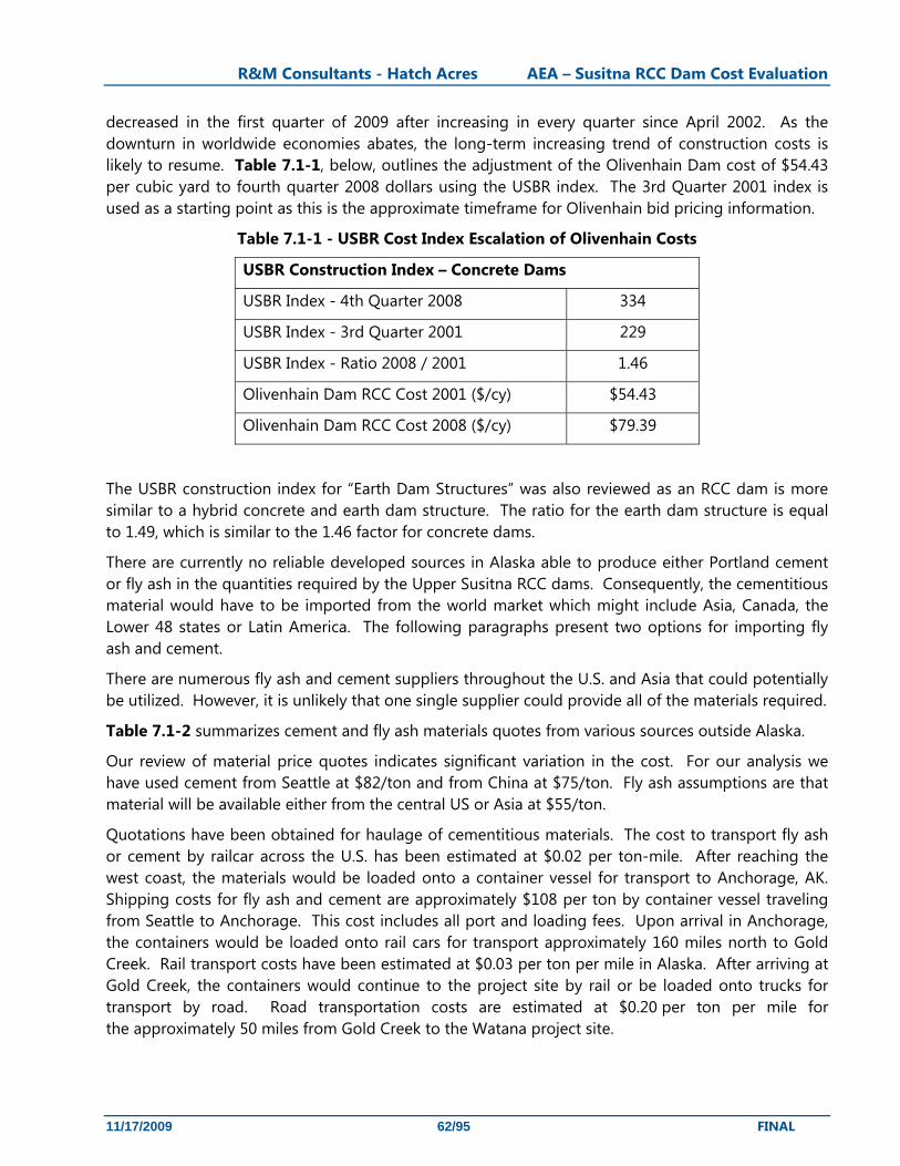
R&M Consultants - Hatch Acres AEA – Susitna RCC Dam Cost Evaluation
11/17/2009 62/95 FINAL
decreased in the first quarter of 2009 after increasing in every quarter since April 2002. As the downturn in worldwide economies abates, the long-term increasing trend of construction costs is likely to resume. Table 7.1-1, below, outlines the adjustment of the Olivenhain Dam cost of $54.43 per cubic yard to fourth quarter 2008 dollars using the USBR index. The 3rd Quarter 2001 index is used as a starting point as this is the approximate timeframe for Olivenhain bid pricing information.
Table 7.1-1 - USBR Cost Index Escalation of Olivenhain Costs
USBR Construction Index – Concrete Dams
USBR Index - 4th Quarter 2008 334
USBR Index - 3rd Quarter 2001 229
USBR Index - Ratio 2008 / 2001 1.46
Olivenhain Dam RCC Cost 2001 ($/cy) $54.43
Olivenhain Dam RCC Cost 2008 ($/cy) $79.39
The USBR construction index for “Earth Dam Structures” was also reviewed as an RCC dam is more similar to a hybrid concrete and earth dam structure. The ratio for the earth dam structure is equal to 1.49, which is similar to the 1.46 factor for concrete dams.
There are currently no reliable developed sources in Alaska able to produce either Portland cement or fly ash in the quantities required by the Upper Susitna RCC dams. Consequently, the cementitious material would have to be imported from the world market which might include Asia, Canada, the Lower 48 states or Latin America. The following paragraphs present two options for importing fly ash and cement.
There are numerous fly ash and cement suppliers throughout the U.S. and Asia that could potentially be utilized. However, it is unlikely that one single supplier could provide all of the materials required.
Table 7.1-2 summarizes cement and fly ash materials quotes from various sources outside Alaska.
Our review of material price quotes indicates significant variation in the cost. For our analysis we have used cement from Seattle at $82/ton and from China at $75/ton. Fly ash assumptions are that material will be available either from the central US or Asia at $55/ton.
Quotations have been obtained for haulage of cementitious materials. The cost to transport fly ash or cement by railcar across the U.S. has been estimated at $0.02 per ton-mile. After reaching the west coast, the materials would be loaded onto a container vessel for transport to Anchorage, AK. Shipping costs for fly ash and cement are approximately $108 per ton by container vessel traveling from Seattle to Anchorage. This cost includes all port and loading fees. Upon arrival in Anchorage, the containers would be loaded onto rail cars for transport approximately 160 miles north to Gold Creek. Rail transport costs have been estimated at $0.03 per ton per mile in Alaska. After arriving at Gold Creek, the containers would continue to the project site by rail or be loaded onto trucks for transport by road. Road transportation costs are estimated at $0.20 per ton per mile for the approximately 50 miles from Gold Creek to the Watana project site.
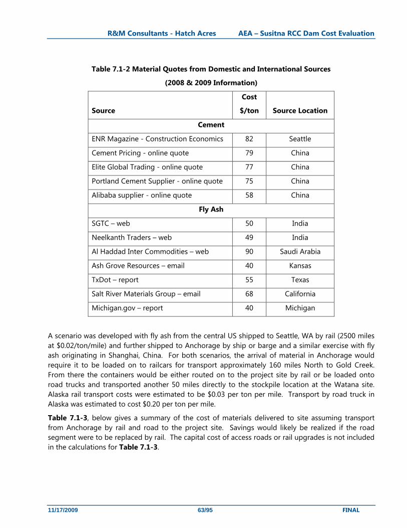
R&M Consultants - Hatch Acres AEA – Susitna RCC Dam Cost Evaluation
11/17/2009 63/95 FINAL
Table 7.1-2 Material Quotes from Domestic and International Sources
(2008 & 2009 Information)
Source
Cost
$/ton Source Location
Cement
ENR Magazine - Construction Economics 82 Seattle
Cement Pricing - online quote 79 China
Elite Global Trading - online quote 77 China
Portland Cement Supplier - online quote 75 China
Alibaba supplier - online quote 58 China
Fly Ash
SGTC – web 50 India
Neelkanth Traders – web 49 India
Al Haddad Inter Commodities – web 90 Saudi Arabia
Ash Grove Resources – email 40 Kansas
TxDot – report 55 Texas
Salt River Materials Group – email 68 California
Michigan.gov – report 40 Michigan
A scenario was developed with fly ash from the central US shipped to Seattle, WA by rail (2500 miles at $0.02/ton/mile) and further shipped to Anchorage by ship or barge and a similar exercise with fly ash originating in Shanghai, China. For both scenarios, the arrival of material in Anchorage would require it to be loaded on to railcars for transport approximately 160 miles North to Gold Creek. From there the containers would be either routed on to the project site by rail or be loaded onto road trucks and transported another 50 miles directly to the stockpile location at the Watana site. Alaska rail transport costs were estimated to be $0.03 per ton per mile. Transport by road truck in Alaska was estimated to cost $0.20 per ton per mile.
Table 7.1-3, below gives a summary of the cost of materials delivered to site assuming transport from Anchorage by rail and road to the project site. Savings would likely be realized if the road segment were to be replaced by rail. The capital cost of access roads or rail upgrades is not included in the calculations for Table 7.1-3.
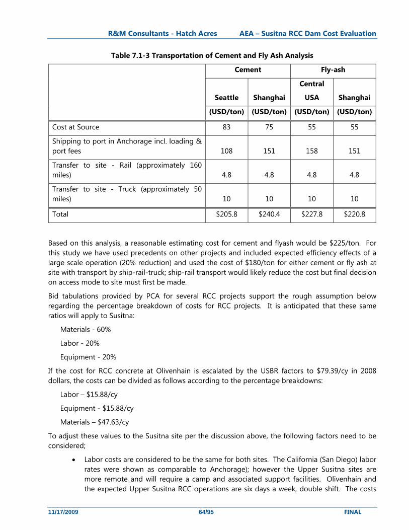
R&M Consultants - Hatch Acres AEA – Susitna RCC Dam Cost Evaluation
11/17/2009 64/95 FINAL
Table 7.1-3 Transportation of Cement and Fly Ash Analysis
Cement Fly-ash
Seattle Shanghai
Central
USA Shanghai
(USD/ton) (USD/ton) (USD/ton) (USD/ton)
Cost at Source 83 75 55 55
Shipping to port in Anchorage incl. loading & port fees 108 151 158 151
Transfer to site - Rail (approximately 160 miles) 4.8 4.8 4.8 4.8
Transfer to site - Truck (approximately 50 miles) 10 10 10 10
Total $205.8 $240.4 $227.8 $220.8
Based on this analysis, a reasonable estimating cost for cement and flyash would be $225/ton. For this study we have used precedents on other projects and included expected efficiency effects of a large scale operation (20% reduction) and used the cost of $180/ton for either cement or fly ash at site with transport by ship-rail-truck; ship-rail transport would likely reduce the cost but final decision on access mode to site must first be made.
Bid tabulations provided by PCA for several RCC projects support the rough assumption below regarding the percentage breakdown of costs for RCC projects. It is anticipated that these same ratios will apply to Susitna:
Materials - 60%
Labor - 20%
Equipment - 20%
If the cost for RCC concrete at Olivenhain is escalated by the USBR factors to $79.39/cy in 2008 dollars, the costs can be divided as follows according to the percentage breakdowns:
Labor – $15.88/cy
Equipment - $15.88/cy
Materials – $47.63/cy
To adjust these values to the Susitna site per the discussion above, the following factors need to be considered;
• Labor costs are considered to be the same for both sites. The California (San Diego) labor rates were shown as comparable to Anchorage); however the Upper Susitna sites are more remote and will require a camp and associated support facilities. Olivenhain and the expected Upper Susitna RCC operations are six days a week, double shift. The costs
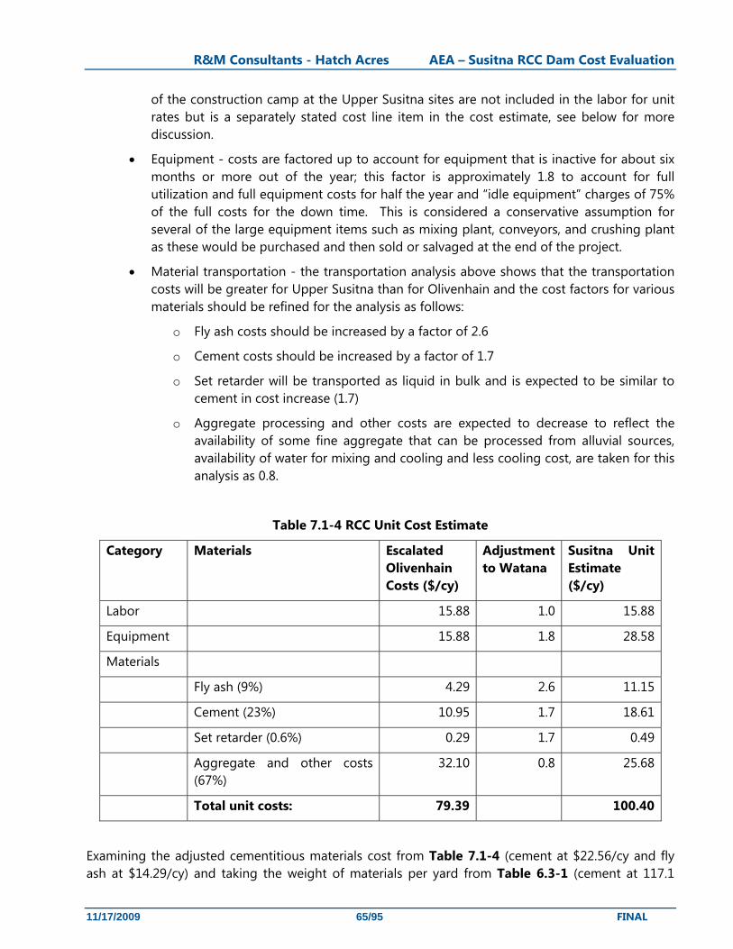
R&M Consultants - Hatch Acres AEA – Susitna RCC Dam Cost Evaluation
11/17/2009 65/95 FINAL
of the construction camp at the Upper Susitna sites are not included in the labor for unit rates but is a separately stated cost line item in the cost estimate, see below for more discussion.
• Equipment - costs are factored up to account for equipment that is inactive for about six months or more out of the year; this factor is approximately 1.8 to account for full utilization and full equipment costs for half the year and “idle equipment” charges of 75% of the full costs for the down time. This is considered a conservative assumption for several of the large equipment items such as mixing plant, conveyors, and crushing plant as these would be purchased and then sold or salvaged at the end of the project.
• Material transportation - the transportation analysis above shows that the transportation costs will be greater for Upper Susitna than for Olivenhain and the cost factors for various materials should be refined for the analysis as follows:
o Fly ash costs should be increased by a factor of 2.6
o Cement costs should be increased by a factor of 1.7
o Set retarder will be transported as liquid in bulk and is expected to be similar to cement in cost increase (1.7)
o Aggregate processing and other costs are expected to decrease to reflect the availability of some fine aggregate that can be processed from alluvial sources, availability of water for mixing and cooling and less cooling cost, are taken for this analysis as 0.8.
Table 7.1-4 RCC Unit Cost Estimate
Category Materials Escalated Olivenhain Costs ($/cy)
Adjustment to Watana
Susitna Unit Estimate ($/cy)
Labor 15.88 1.0 15.88
Equipment 15.88 1.8 28.58
Materials
Fly ash (9%) 4.29 2.6 11.15
Cement (23%) 10.95 1.7 18.61
Set retarder (0.6%) 0.29 1.7 0.49
Aggregate and other costs (67%)
32.10 0.8 25.68
Total unit costs: 79.39 100.40
Examining the adjusted cementitious materials cost from Table 7.1-4 (cement at $22.56/cy and fly ash at $14.29/cy) and taking the weight of materials per yard from Table 6.3-1 (cement at 117.1

R&M Consultants - Hatch Acres AEA – Susitna RCC Dam Cost Evaluation
11/17/2009 66/95 FINAL
lb/cy and fly ash at 219.1 lb/cy) yields a cost of $385/ton for cement and $130/ton for fly ash. With the pricing assumption for cement and fly ash at $180/ton we calculate the cost of cementitious material as being [$180/ton x (117.1 lb/cy+219.1 lb/cy)/2000 lb/ton] = $30.26/cy which is within a dollar of the escalated Olivenhain costs which is reasonable considering the larger scale and less restrictive access. We have used $100/cy for RCC in this estimate.
Construction cost indices were reviewed as a test of relative costs of construction at Olivenhain near Escondito vs Watana site. Review of city cost indexes in the R.S. Means Heavy Construction Cost Data index suggests a premium allowance for Alaskan material and installation is necessary. Table 7.1-5 shows the city index data for site work and concrete between San Diego and Anchorage. The city indexes listed below are relative only and are based on a baseline of 100.00 for the 30 major city U.S. average.
Table 7.1-5 RS Means comparison of San Diego to Anchorage
Division Material Installation Total City Index – Anchorage
Site Work 143.7 133.7 136.4 Concrete 153.60 113.50 133.70
City Index ‐ San Diego Site Work 101.2 100.7 100.8 Concrete 112.90 107.90 110.40
Ratio Anchorage/San Diego Site Work 1.42 1.33 1.35 Concrete 1.36 1.05 1.211
The ratio of estimated Upper Susitna to Olivenhain RCC costs of 1.36 is quite similar to ratio of material cost for Anchorage to San Diego, which provides some level of comfort that the process for transferring costs makes sense.
7.1.2 Comparison to PCA trend
The PCA trend analysis indicates a much lower cost per unit than indicated by the modification to the Olivenhain cost numbers (see Figure 7.1-1). The size of the Upper Susitna projects will include economies of scale, however there will also be logistical challenges that will occur for an enterprise of this size. Given the number of unknowns, the modified cost of the Olivenhain project is considered more appropriate than a trend line based on a curve fit number. There remains the potential for refining the estimate and potentially reducing the estimated cost of the dam construction.
7.1.3 Construction Materials (Portland cement and Pozzolan)
Large supplies of Portland cement and supplementary cementitious material (SCM) will be required for this project. SCM will be either fly ash or pozzolans processed from natural deposits. These materials are available from sources in the Lower 48 states or from abroad.
A project of the scale of Watana or High Devil Canyon dam as an RCC project could provide the impetus for establishing cement and/or pozzolan industries in Alaska.
R&M Consultants - Hatch Acres AEA – Susitna RCC Dam Cost Evaluation
11/17/2009 67/95 FINAL
To develop a viable source for cement and/or pozzolan in Alaska would require a significant investment and would depend greatly on whether the permitting and access issues can be resolved in a timely manner. In order to determine if the materials are available locally to develop these materials, we have performed a desk study of geotechnical resources that may supply the material required .for these industries.
7.1.3.1 Location of Limestone Deposits for Portland Cement Production
Several areas have been identified as having limestone deposites that may have the potential for development into sources of cement. The locations are as follows:
1) Kings River - Deposits of limestone on Kings River (approx. 61° 51' 07" north and 148° 33' 31" west) were staked and future plans for a $5 million dollar cement manufacturing plant to be constructed near Sutton, adjacent to the Alaska Railroad spur were announced by Kaiser Permanente Co. in August 1960 (Alaska Division of Mines, 1960). The deposit is between 8 and 17 miles north of the Glenn Highway at elevations ranging from 2,500 to 6,000 feet. Eight (8) to 17 miles of haul road would need to be constructed to connect the site with the Glenn Highway. The deposit is about 65 miles south of the proposed dam site but approximately 150 miles along existing highways or the Alaska Railroad.
The deposits are extensive and preliminary sampling and testing indicates nearly pure calcium carbonate (Mihelich and Jasper, 1961).
2) Cantwell-Windy Area - Deposits in this area have been evaluated by the U.S. Geological Survey since 1931. Prior to November 1960, claims were purchased by Alaska Portland Cement, Ltd., a California corporation. Additionally, Alaska Portland Cement, Ltd., along with Bechtel Corporation and Allis Chalmers investigated construction of a cement plant. One deposit was estimated at exceeding 200 million tons (Alaska Division of Mines, 1960).
The Windy deposit is situated at 63° 26' 45" north and 148° 57' 00" west and is located in the southeastern corner of Denali National Park and is within the area designated as “wilderness”. The limestone outcrops at altitudes of 2,600 and 3,200 feet. The lower outcrops are slightly over 1 mile northwest of Mile 323.1 of the Alaska Railroad. Core drilling (12 test holes with over 3,000 feet of core) and sample testing results are available (Rutledge et al, 1953).
Numerous other deposits of similar limestone have been identified in the Windy Creek and West Fork of the Chulitna River areas including Foggy Pass (Warfield, 1962). These other deposits are not as accessible to the railroad as the Windy deposit.
3) Fox - A small deposit of limestone has been identified within the Birch Creek Schist at the junction of the Elliott and Steese Highways near Fox. The deposit was mapped as approximately 15 feet thick (Rutledge et al, 1953).
This deposit is approximately 200 miles north of the proposed access to the dam site.
4) Seldovia - Limestone deposits at Seldovia Bay have been considered for use in industry and agriculture since about 1911. After World War II, consideration was given to the use of

R&M Consultants - Hatch Acres AEA – Susitna RCC Dam Cost Evaluation
11/17/2009 68/95 FINAL
the material for the production of cement. The Alaska Cement Corp. obtained claims and also considered several locations for a cement plant (Rutledge, 1953). No production from this site has been made.
The deposit is located on the Kenai Peninsula, approximately 260 miles southwest of the dam site. Barge loading and unloading facilities would need to be constructed both near the deposit site and in the Anchorage area.
7.1.3.2 Location of Pozzolanic Material
Deposits of natural pozzolans, tuffaceous materials or basalt deposits could be used to develop local sources of pozzolans for use in RCC mix.
1) liamna Quadrangle - Pozzolans have been evaluated to a limited extent in Alaska since about the early 1950s. Initial testing by the Bureau of Reclamation of pumice from Katmai National Monument indicated that the material would be satisfactory in strength development but is not outstanding (Rutledge, 1953). Further testing by the Bureau of Mines (1966) indicted that Katmai National Monument pumice (Dossier No. 1) is a good pozzolan, possibly an excellent one.
Pumice as a lightweight aggregate occurs east of Katmai National Monument on Augustine Island. Between 1946 and 1949, pumice was mined on Augustine Island by the Alaska Katmalite Corp. (Detterman and Reed, 1980). A major deterrent to developing a mining operation on the island is the continued threat of a major volcanic eruption.
Detterman and Reed (1980) map numerous volcanic rocks including lava flows, pyroclastics, pumice, scoria, tuff, basalt and andesite within the Iliamna quadrangle. The Iliamna quadrangle is located between about 250 and 300 miles southwest of the proposed dam site. Land status within the area is rather complex including federal, state, native and private ownership. Mining operations for pozzolan within the area would require the development of mine roads and barge loading and unloading facilities both near Iliamna and in the Anchorage area.
2) Talkeetna Mountains and Healy Quadrangles - The proposed dam site lies within the Talkeetna Mountains USGS quadrangle. Csejtey et al, 1978 and Csejtey, 1974 map undivided sedimentary and volcanic rocks in the northern Watana Creek area. The volcanic rocks include volcanic ash or fine-grained tuffaceous material and flows and dikes of andesitic to latitic feldspar porphyry. Metabasalt also occurs in the area.
Richter (1963) mapped rhyolite flows or welded tuff within about four (4) miles northwest of the proposed High Devils Canyon dam site. The deposit was characterized as a small outcrop of relatively soft, unaltered rhyolite flow or welded tuff which appeared to unconformably overlie the sedimentary rocks. Richter further considered that this rock represents an erosional remnant of a post-Mesozoic volcanic sheet.
3.) Mount McKinley Quadrangle - Gilbert et al, 1976, mapped rhyolite, andesite and basalt flows in the Polychrome Mountains area within the eastern part of Denali National Park.

R&M Consultants - Hatch Acres AEA – Susitna RCC Dam Cost Evaluation
11/17/2009 69/95 FINAL
These deposits are about 75 to 100 miles northwest of the proposed dam site. Material from this general area was tested in about 1965 by the Bureau of Mines. Testing is referenced in Bureau of Mines (1966) with the results from Katmai; however actual test results have not been located.
7.1.3.3 Viability of Developing Local Cementitous Products
Materials are available and the project is large enough to attract the attention of manufacturers of cementitous products. However further evaluation would be required to establish if efficiencies would have significant effect on the cost of materials for construction of the dam.
7.2 Project Access
Access to the Susitna Project Dam Sites was considered by the USACE in their 1975 Susitna Project report. The USACE study was expanded in the early 1980’s Susitna Project Studies for APA to include alternatives for access corridors from the Parks and Denali Highways along the north and south sides of the Susitna River for access to all the selected Susitna Project dam sites that may be proven feasible. A report on the Access Planning Study by R&M for Acres was issued in January 1982 and a Supplement to the Access Planning Study was issued in September 1982. The USACE identified an access corridor beginning at the Parks Highway near Chulitna Station then paralleling the Alaska Railroad south and east to a crossing of the Susitna River then proceeding east up the south side of the Susitna River to the Devil Canyon site and on to the Watana site via the north end of Stephan Lake and the west end of Fog Lakes. Also a rail head was planned at Gold Creek in the USACE study. Both a road and railroad are considered essential for access to the projects for construction of the RCC dam. A railroad because of the quantities of bulk materials to be moved to the construction site and weights anticipated for large components such as gates, penstocks, turbines, generators and transformers and because a railroad would lessen the impact of project traffic and heavy haulage on the Alaska highway system. In addition, the fact these material and equipment items will likely be brought to Alaska by barge and/or ship from the source either via Seattle or other foreign or domestic port to Anchorage or Whittier for trans-loading onto railcars for movement to the Project site. Shipping possibilities include rail barge for much of the materials which would allow the loaded rail cars to pass through Whittier or Anchorage directly to the project site without trans-loading. Materials shipped in sea containers (CONEX’s) could be offloaded from a container ship in Anchorage and loaded on rail cars for hauling to the project site. With a road, trucks, buses and passenger vehicles associated with the project can move by the Parks Highway to the Susitna Project road and travel directly to the project(s).
Based on the 1982 Acres Feasibility Study (Acres 1982), access to the High Devil Canyon and Watana Sites is practicable via the south corridor from Gold Creek to High Devil Canyon with the road then extended to Watana in the north corridor for purposes of cost estimating. The selected access plan for construction and operation of the Susitna Project RCC dams should comprise a road commencing near MPP 156 on the Parks Highway, proceeding southeast and crossing the Susitna River at Gold Creek on a major bridge, turning northeast to High Devil Canyon damsite along the south side of the
R&M Consultants - Hatch Acres AEA – Susitna RCC Dam Cost Evaluation
11/17/2009 70/95 FINAL
Susitna River, and proceeding on along the south side of the Susitna River to Watana damsite (see Figure 7.2-1). To accommodate the access to the High Devil Canyon site, the cost of the Devil Canyon road has been increased proportionally to the additional distance from Devil Canyon to the High Devil Canyon site. A rail road spur line extension from Gold Creek to High Devil Canyon and on to Watana is considered practicable as well and has been included in the cost estimate for both the High Devil Canyon RCC dam and the full height Watana RCC dam.
7.2.1 Watana Site Access
7.2.1.1 Roads
For the Watana RCC dam the main access road will originate at MP 156 on the Parks Highway, cross the Susitna River and proceed via Gold Creek along the south side of the Susitna River. In addition to the main access, several additional roads will be required to the construction camp, support facilities, airstrip, and tank farm. Haul roads to the borrow areas and construction roads to the dam and all major structures will also be required. These roads with the exception of the haul roads are shown on Figure 7.2-1.
The construction roads will be 40-foot wide gravel surfaced roads with small radius curves and grades limited to 10 percent. Major cut and fill work will be avoided. A gravel pad approximately 5 feet thick will be required for the roads. This gravel pad will provide a drivable surface and also will provide for road construction requirements over the sporadic permafrost areas.
7.2.1.2 Railroad
A railhead will be constructed at Gold Creek and railroad access constructed to the Watana site along the South access corridor to provide for heavy hauling requirements for RCC dam construction; see Figure 7.2-1.
7.2.1.3 Bridges
No major temporary bridges at the Watana site will be required for the construction of the Watana development. The crest widths of the upstream and downstream cofferdams will be planned to provide suitable access to the north bank of the Susitna River during construction.
The completed main dam crest will provide permanent access across the Susitna River for project operational purposes.
7.2.1.4 Airstrip
A permanent airstrip would be constructed at a suitable location near the main construction camp. The runway is assumed to be 6,000 feet in length based on the project final report and to be capable of accommodating the C-130 Hercules aircraft, as well as small jet passenger aircraft. If construction personnel transport were to be done by using jet aircraft such as the Boeing 737-400 or similar, the runway would require greater length and to be constructed to generally higher standards than that serving the C-130 aircraft. Roads will connect the airstrip to the camp, village, and dam site. A small building will be constructed to serve as a terminal and tower and a fuel truck/maintenance facility will be constructed. Also a helicopter pad will be provided.
R&M Consultants - Hatch Acres AEA – Susitna RCC Dam Cost Evaluation
11/17/2009 71/95 FINAL
A temporary airstrip would also be constructed to support the early phases of mobilization and construction. This temporary runway will be 2,500 feet in length and will be located in the vicinity of the main construction camp. The airstrip will be capable of supporting smaller type aircraft.
The temporary airstrip would eventually be incorporated into one of the main haul roads after the permanent airstrip is in service.
7.2.1.5 Access Tunnel
The concept for the Watana powerhouse presented in the project feasibility studies in the 1980’s was for an underground powerhouse and appurtenant facilities. Thus for the base case RCC dam an underground powerhouse is also provided which requires that an access tunnel be provided to the underground powerhouse and associated works. As assumed in the 1980’s studies the main access tunnel will be approximately 35 feet wide and 28 feet high. The tunnel will allow permanent access to the operating facilities development and will also be utilized during construction as the main construction tunnel. Construction adits will branch off to the various components of the development during construction. It would be possible to construct a surface powerhouse in close proximity to the RCC dam and reduce the extent of tunnelling and underground works presently in the cost estimate to a much lower number. Future studies are recommended to develop the surface powerhouse concept further.
7.2.2 High Devil Canyon Site Access
7.2.2.1 Roads
For the High Devil Canyon RCC dam the main access road will originate at MP 156 on the Parks Highway, cross the Susitna River and proceed via Gold Creek along the south side of the Susitna River. At High Devil Canyon the main access road will enter the site from the south (assumed to be an extension from the previously considered Devil Canyon site access road). A low level bridge crossing the Susitna River could be located just upstream of the dam for the construction phase prior to availability of the cofferdams for access across the river. In addition to the main access, several auxiliary roads will be required to the camp, support facilities, tank farm, borrow sites, and construction areas. These roads with the exception of the haul roads are shown on Figure 7.2-1.
The construction roads will be gravel-surfaced roads 40 feet wide with small radius curves. Grades will be limited to 10 percent. Major cut and fill work will be avoided where possible. A gravel pad, approximately five feet thick, will be required for the roads. This will provide a drivable surface and also will protect against settlements and heaving caused by localized frost sensitive soils and permafrost.
7.2.2.2 Railroad
A railhead will be constructed at Gold Creek and railroad access constructed to the High Devil Canyon site along the South access corridor to provide for heavy hauling requirements for RCC dam construction; see Figure 7.2-1
R&M Consultants - Hatch Acres AEA – Susitna RCC Dam Cost Evaluation
11/17/2009 72/95 FINAL
7.2.2.3 Bridges
A low level bridge constructed upstream of the dam will be used during abutment excavation. Once construction of the cofferdams are complete, the crests of these structures will be used for river crossing.
After completion of the main dam, the crest of the dam will provide access across the Susitna River.
7.2.2.4 Airstrip
The same sort of airstrip (6,500-foot) as considered for the Watana site has been assumed for the HDC site. The airstrip will be capable of accommodating both C-130 Hercules aircraft and small jet passenger aircraft and a helicopter pad will be provided. An airstrip that could accommodate larger jet aircraft such as the Boeing 737-400 is not included in the cost estimate and would require further study to determine the economic feasibility of transporting personnel by air to the HDC project during construction when permanent road and rail road are available for the relatively short trip from the Parks Highway.
7.2.2.5 Access Tunnel
The concept for the HDC powerhouse is identical to the Watana powerhouse presented in the project feasibility studies in the 1980’s was for an underground powerhouse and appurtenant facilities. Thus for the base case RCC dam an underground powerhouse is also provided which requires that an access tunnel be provided to the underground powerhouse and associated works. As assumed in the 1980’s studies the main access tunnel will be approximately 35 feet wide and 28 feet high. The tunnel will allow permanent access to the operating facilities development and will also be utilized during construction as the main construction tunnel. Construction adits will branch off to the various components of the development during construction. It would be possible to construct a surface powerhouse in close proximity to the RCC dam and reduce the extent of tunnelling and underground works presently in the cost estimate to a much lower number. Future studies are recommended to develop the surface powerhouse concept further.
7.3 Camp/Project Village for Watana and HDC
The 1982 Acres Feasibility Study cost estimate had assumed for the Watana embankment dam a camp for 3,600 workers, a project village and support facilities. Considering the RCC dam alone the smaller volume of the RCC dam would logically reduce the workforce required. The RCC dam is approximately one-fourth the volume of the embankment dam, and assuming the embankment dam construction workforce size is directly related to the volume of the dam, the estimated number of construction workers required for the RCC dam is estimated to be one-fourth of those required to construct the embankment dam. One-quarter of the total main construction camp cost was reduced by 75% which resulted in the camp for the RCC dam construction costing about 20 percent less than that for the embankment dam concept (factor of 18.75% was used in calculations).
7.4 Review of Acres Cost Estimate Back up Material
Review of Hatch Acres internal records has recovered detailed cost estimate backup records that were the basis for the cost estimate labor and equipment production rates that were used in the

R&M Consultants - Hatch Acres AEA – Susitna RCC Dam Cost Evaluation
11/17/2009 73/95 FINAL
1982 Acres Feasibility Study. We have examined these estimates to review equipment production rates and labor assumptions to determine if they are consistent with modern equipment and labor practices for large earthwork projects.
The 1982 and 1985 Estimates were prepared in significant detail regarding construction costs – including direct labor, permanent materials, construction supplies, construction equipment costs, and subcontracts. We have found no reason to question the various production rates, equipment spreads, etc – inasmuch as total progress on such a Project as Susitna is affected by climatic conditions more so than manpower or size of equipment.
Labor wage rates have increased since the 1982, 1985 estimates by factors of 1.65 and 1.42 respectively. Equipment costs have at least doubled – largely influenced by fuel costs. Materials for construction (cement, rebar, farm lumber, etc) have been volatile in costs recently, but ENR records suggest the average annual increase over the years has been in the 3-4% range.
Estimates of Overhead/Profit/Supervision were added using a factor that was not clearly documented in the records uncovered. This factor may in part recognize the significant overtime factors for these remote jobs, which could be in excess of 16% of all labor (6-10’s = 60 hr work for 70 hrs pay).
The 1982 and 1985 cost estimates were prepared in great detail and we are not prepared to comment on the calculations in any detail – other than to say that the production rates, manpower spreads and equipment choices are appropriate for this work. Nevertheless, the calculations have been used to develop unit prices which then were extended to takeoff quantities.
Construction efficiencies have improved in earthwork and tunnelling, however the use of the very large mining equipment that could improve the productivity of earthwork are limited by the size of the site and expected grades for transfer of material from borrow areas to the work site. Tunnel boring machines are not expected to be efficient given the relatively short length of the tunnels on the project.
7.5 Cost Summary
The Watana RCC dam cost estimate utilizes the information and the format of the 2008-based cost estimate HDR/DTA updated to the extent that it is possible to maintain an “apples to apples” comparison of the concepts. In areas where there are modifications to the earth embankment dam project due to the alternate RCC dam configuration, new quantities and unit prices were developed reflecting the change in technology. We have stated costs of the RCC concepts in December 2008 dollars to be consistent with the HDR/DTA cost estimate.
The cost estimate summary, Table 7.5-1, summarizes the estimated cost of the Watana RCC dam and High Devil Canyon RCC dam options. A detailed summary of costs is presented in Appendix B and detailed costs are included in Appendix C for Watana RCC dam and Appendix D for High Devil Canyon RCC dam. The cost estimates focus on the RCC dam and scales the cost of project features/facilities such as the power tunnel/power conduits, powerhouse, switchyards, transmission lines, site road and rail access, operations support facilities and similar features as they are affected by details of the RCC dam options.

R&M Consultants - Hatch Acres AEA – Susitna RCC Dam Cost Evaluation
11/17/2009 74/95 FINAL
Costs estimated for the full height Watana RCC dam are based on the Watana earth embankment dam as escalated from the 1982 estimate to December 2008 by HDR/DTA and this is the basis AEA regards as the current base for cost estimates under the current studies. The R&M teams’ analysis of costs for the Watana RCC dam retained all costs by detailed account category and subcategory as stated in the 2008 base estimate and modified only the costs directly relevant to the RCC dam concept in place of the earth embankment dam. The cost of the High Devil Canyon dam was also drawn from the Watana 2008 base costs with adjustments for volume of an embankment dam at the HDC site from which to estimate the HDC RCC dam. In developing the RCC dam costs, the access tunnels, underground powerhouse and hydraulic works in the Watana 2008 basis estimate were retained for both of the RCC dams and both RCC concepts studied have been estimated with identical 1200 megawatts of installed capacity in the powerhouses. The embankment dam concept for High Devil Canyon was not developed to the level of the Watana estimate used as the basis for the HDR/DTA cost estimate. To develop our comparison embankment dam cost for High Devil Canyon, we have utilized a portion of the site selection cost estimate summaries presented in Table 8.3 of the 1982 Acres Feasibility Study which includes preliminary cost information on both High Devil Canyon and Watana. We have assumed that the cost of the High Devil Canyon “Reservoir, Dams and Waterways” portion of the cost estimate is proportional to the ratio of the High Devil Canyon to Watana “Main Dam” and “Spillway System” costs form the above referenced table times the Watana “Reservoir, Dams and Waterways” costs.
The level of study for the RCC alternative is far less extensive than that for the embankment dam. The material and equipment costs used for the RCC unit price costs are considered to be conservative and we applied higher contingencies to the portions of the project that were modified for the RCC dam configuration than had been used in the HDR/DTA cost estimates. The modified items were approximately one third of the total costs, so the contingency was adjusted to 21.67% to reflect one third of the permanent features of the project (RCC) at 25% contingency and two thirds (unchanged by RCC) at 20% contingency.
Table 7.5-1 Summary of Costs of RCC Dams for Watana and High Devil Canyon Sites
Description Watana RCC
$1,000 HDC RCC
$1,000 Engineering 4%, Env.2% & Regulatory 1% $ 341,700 $ 281,400 Dam & Power Facilities $ 4,304,100 $ 3,700,600 Transmission Features $ 322,000 $ 119,400 Other Tangible Property $ 11,900 $ 11,600 Main Construction Camp $ 244,200 $ 189,100 Construction Management 4% $ 195,300 $ 160,800 Total Subtotal $ 5,419,200 $ 4,462,900 Total Contingency $ 1,155,000 $ 954,000 Total (Millions of Dollars) $ 6,600 $ 5,400
R&M Consultants - Hatch Acres AEA – Susitna RCC Dam Cost Evaluation
11/17/2009 75/95 FINAL
It should be noted that all estimates shown include the underground powerhouse scheme developed for the embankment dam options. Use of intakes integral to the dam, water conveyances through the RCC dam and a surface powerhouse directly downstream of the RCC dam represent potential for significant cost savings in project construction. The surface powerhouse configuration would eliminate significant tunnelling and excavation for these features and reduce project head losses.
To determine an order of magnitude cost for the surface powerhouse, we have utilized comparison tables developed by the USBR. The USBR table shows relative powerhouse structure and equipment costs for a range of installed capacities. The relative costs can be updated to reflect broad changes in the costs of equipment and structures using the USBR cost indices. The powerhouse structure costs can then be estimated as a percentage of the updated (2008) cost of the large generating equipment. Preliminary estimates of the potential reduction in cost (based on the estimated cost of excavations and rule of thumb costs for surface powerhouses) indicate that the cost reduction may be on the order of $500 million; however a more in depth study would be required to adequately address the issues associated with a design change of this scope.

R&M Consultants - Hatch Acres AEA – Susitna RCC Dam Cost Evaluation
11/17/2009 76/95 FINAL
8. Project Timeline for Licensing and Construction
In formulating our view of the Project timeline for licensing and construction of the Susitna Project we reviewed the March 16, 2009, HDR/DTA Final Report, and several documents prepared by Acres International and Harza Ebasco during the 1980’s for the Alaska Power Authority (APA). We also have considered the observations made during the 1980’s timeframe by James Thrall, PhD, who was involved in the Harza Ebasco studies for APA resulting in the 1985 Amendment to the License Application, and Nan Nalder, MPA, who served as Staff in the Federal Energy Regulatory Commission (FERC or Commission) Hydropower Licensing Division when the 1982 Draft and 1983 Final Original Applications for License prepared by Acres were filed and under FERC Staff review. Their experience and insights are reflected in statements regarding the activities during the 1980’s and recommendations based on that experience and current knowledge of the FERC licensing process and experience with Alaska hydroelectric projects from the 1980’s up to the present.
The following paragraphs provide our thoughts regarding the original (1980’s) project schedule information provided in the HDR/DTA Final Report and includes identified concerns which are summarized graphically in the proposed schedule for Susitna Project Licensing in the attached Figure 8.1-1. The following paragraphs recommend issues that need to be considered by the Alaska Energy Authority (AEA), known as the Alaska Power Authority (APA) during the time that the Original Application was filed with the FERC and the subsequent investigations and revised Application up through the date when the Susitna Hydroelectric Project (Susitna Project or Project) was cancelled in 1986.
8.1 A Brief Review of the Susitna Project
Beginning in the 1950’s, State- and Federally-sponsored studies were performed to assess the potential for hydropower development in the Susitna River Basin. In 1980, APA contracted with Acres American, Inc. (Acres), now known as Hatch Acres Corporation (HAC) to conduct studies and investigations in support of an Application for FERC License. The Acres feasibility study, completed in 1982, reaffirmed prior conclusions of the U. S. Army Corps of Engineers (USACE) that a two-dam project at the Watana and Devil Canyon sites represents the preferred plan for development of the hydro potential of the Susitna River. An independent review was conducted by Battelle Pacific Northwest Laboratories who concluded that the Susitna Project, over the long term, was the preferred means for providing power to the Railbelt. Based on this consistent analytical support for the Susitna Project, the APA filed its Final Application for License with the FERC in February 1983 (1983 Application).
In May 1985, APA concluded that substantial benefits would be realized with modification of the construction plan proposed in the 1983 Application to change the construction staging from two to three stages. This approach was driven by interest to reduce the initial costs of construction by reducing overall labor and material requirements for the Watana development. The proposed three-year staging would permit development of generation capacity from the Project to more closely match the estimated Railbelt load growth and replacement of existing fossil-fuel generation capacity. This proposed modification required preparation and filing of an Amendment to the Application for License. APA engaged the services of the Harza/Ebasco team to prepare the Amendment to the
R&M Consultants - Hatch Acres AEA – Susitna RCC Dam Cost Evaluation
11/17/2009 77/95 FINAL
License. In November 1985, APA provided a Draft Application for Amendment to License (Draft Amendment) for review and comment by stakeholders.
The Draft Amendment included an economic re-evaluation that again presented the conclusion that the Susitna Project would be, over the long term, the least cost resource to meet future load growth in the Railbelt region of Alaska (Railbelt). APA’s guiding policy to develop the hydropower potential of the Susitna River was “no net loss of beneficial habitat for fish and wildlife.” The 1985 Draft Amendment includes plans for mitigation of potential project-related adverse effects. Mitigation measures proposed in the Draft Amendment contemplate an investment of over $300,000,000 over the life of the Project. Measures include special design features to accommodate water quality concerns, habitat modification to facilitate fish migration and spawning, and a comprehensive monitoring program that would be implemented over the life of the project.
In 1986, the APA abandoned its pursuit of a FERC license for numerous reasons including financial feasibility.
In 2008, the Alaska State Legislature authorized AEA to perform an update of the project. That authorization included preparation of a Railbelt Integrated Resource Plan (RIRP) to evaluate the ability of the Susitna Project and other potential energy sources to meet long term demand in the Railbelt region of Alaska.
The HDR/DTA Final Report addressed the proposed project development alternatives as presented in the 1985-86 FERC Amendment documents, Notes from 1985-86 regarding FERC likely acceptance are noted at the Staged alternative:
• Watana Dam comprised of a large storage reservoir with an 888-foot high rock fill dam, and a powerhouse containing 6 units with total installed capacity of 1,200 MW.
• Low Watana Dam would include a 700-foot high dam with powerhouse containing 4 units and total installed capacity of 600 MW.
• Watana/Devil Canyon comprised of Watana Dam discussed above and a second 646-foot high concrete dam and reservoir located downstream at Devil Canyon. The downstream reservoir would re-regulate flow from Watana. A powerhouse would have an installed capacity of 680 MW. The proposed Application for License would present a sequenced approach for construction. Combined installed capacity would be 1,880 MW.
• Staged Watana/Devil Canyon (low Watana Dam, Devil Canyon and high Watana). Watana Dam would be initially constructed at 700-feet with a powerhouse containing 4 units and space for two additional units. Following completion of Low Watana, the construction crew would demobilize and move downstream to Devil Canyon, and later move upstream to Watana to raise the dam. This proposed scheme would be difficult to present to FERC in a comprehensive Application for License unless APA were to state unequivocally that they would construct all three proposed facilities. If APA were to adopt this approach, APA would need to prepare a description of the approach and the planned facilities and consult with

R&M Consultants - Hatch Acres AEA – Susitna RCC Dam Cost Evaluation
11/17/2009 78/95 FINAL
FERC Staff in the Office of Energy Projects (OEP), Division of Hydropower Licensing (DHL) and the Office of General Counsel (OGC).
• Devil Canyon comprised of the Devil Canyon Dam and powerhouse containing 4 turbines
with a total installed capacity of 680 MW.
AEA requested R&M Consultants, Inc. (R&M), and its subconsultant Hatch Acres Corporation (HAC) including Jack Linnard Consulting, to conduct a review of the Susitna Project based on data presented in the HDR/DTA Final Report and prepare analyses of: a full Watana RCC Dam development, and a High Devil Canyon RCC dam development. This section of the report addresses the regulatory and environmental issues and provides recommendations should AEA determine that the Susitna Project is feasible and authorize preparation of an Application for License for the preferred alternative project configuration.
8.2 Proposed Project FERC Licensing Schedule
It is noted that the project schedule in the HDR/DTA report is based on the 1985-86 application schedule and related recommendations on the Integrated Licensing Process (ILP). For reasons discussed below at Section 8.4, we provide options for consideration by AEA regarding the selected FERC pre-filing licensing process.
First, and perhaps most critical in terms of moving the project along, there is no time allotted in the presented schedule to advertise for and select a contractor or contractors to carry out the licensing precursor work. Given the magnitude of the proposed effort it will be necessary to competitively bid this work. A diverse team including an engineering design team, an environmental firm, a geotechnical/earth-science firm and a licensing consultant will be required. This process will take significant time and until the team is on board the other activities shown on the schedule will not proceed. Thus the procurement process to acquire the services of the team should be initiated as soon as possible.
Second, there are concerns with the assumption that: “Roads and staging will be state permitted outside the FERC project and will begin several years before FERC license, including pioneer and permanent roads, airports, bridges, construction camps, staging areas, and towns. Building roads in this way is the quickest way to meet the projected timeline although there is some uncertainty whether permits could be obtained to construct these facilities before the project license is issued.” The proposal to begin construction of major infrastructure for the project prior to receipt of a license is very unlikely to be acceptable to FERC. In the past, FERC has closed down construction of roads to access project sites where construction was begun prior to license issuance. FERC regulations require approval of the construction package prior to commencement of construction of any and all project facilities. Even if FERC were to waive the regulations requiring approval of construction of project-related infrastructure, such a venture would be a major risk for the state if the sole purpose of roads and any other infrastructure were to facilitate development of the hydro project. The assumption that “Construction will begin immediately upon issuance of the license” and several related assumptions provide similar challenges for the reason that the construction package, including all related permits, must be filed for Federal Energy Regulatory Commission approval prior to commencement of construction.

R&M Consultants - Hatch Acres AEA – Susitna RCC Dam Cost Evaluation
11/17/2009 79/95 FINAL
Third, we recommend that an outreach effort to stakeholders be initiated and maintained; it should commence immediately. Furthermore, in keeping with the FERC pre-filing requirements, consultation with all stakeholders should be documented. Summary reports of such consultations should be prepared and copies provided to consulted federal and state agencies with a request for their concurrence on the summary reports.
Finally, the time allotted for FERC issuance of a license extends for a longer period than is justified given review of recent FERC proceedings. FERC Staff cannot provide a schedule for license processing through decision regarding issuance of an Order Issuing License. We anticipate that issuance of the license will include a requirement for an Environmental impact Statement (EIS). We also anticipate that the “Applicant” for License will prepare the environmental document required by the FERC regulations for a NEPA format as opposed to the Environmental Exhibit E, following guidance in the FERC document: “Preparing Environmental Documents – Guidelines for Applicants, Contractors, and Staff issued September 2008. The environmental document “Preliminary Draft Environmental Assessment” or a Draft Environmental Impact Statement prepared by a third-party contractor agreed to by the Applicant and FERC staff will need to be prepared. That NEPA document provides information that FERC Staff can adopt and augment with their own independent analysis to prepare the FERC EIS. Once FERC Staff complete their NEPA document and prepare an Order Issuing License for consideration by the FERC Commissioners, unless there are significant issues that are not resolved in the FERC Staff NEPA document, the Order is set for issuance at the next available Commission meeting.
We note that once the Commission issues an Order Issuing Original License for a Major Unconstructed Project (License Order), there is opportunity for Applications for Rehearing that FERC may or may not entertain. Unless there is a Request for Stay of License accepted by the Commission, Applications for Rehearing do not affect the effective date of the License. Following considerations for Rehearing and Commission action either to reject or amend the license as issued, the License is determined Final. If a party who filed request for rehearing still has major problems with the license as issued, the party could request review in the U.S. Court. If a Court grants a petition to review the FERC license, the time when the license is final could be significantly delayed. We do not include the potential for a Stay of License or a U.S. Court proceeding in the proposed schedule as there is no possible way to estimate the delay associated with such actions by third parties.
A revised Project Licensing Schedule is presented as Figure 8.1-1.
8.3 Stakeholder & Resource Agency Coordination and Settlement Process
At the time that the Susitna licensing work was discontinued in 1986, APA was engaged in a settlement process. At that time settlement between an applicant and stakeholders, undertaken without FERC participation, was considered risky and there was some resistance from the attorneys to this program. Nevertheless APA decided to attempt to settle as many of the environmental issues as possible and take the agreements reached to FERC for approval and incorporation into the license terms. It was felt that some of the issues (in particular, in-stream allocations) might not be settled and APA might only achieve partial settlement.
R&M Consultants - Hatch Acres AEA – Susitna RCC Dam Cost Evaluation
11/17/2009 80/95 FINAL
Nevertheless APA elected to pursue the settlement. This process was to have consisted of the following steps:
• Issue Identification - In consultation with the agencies and other stake holders, APA expended considerable effort to identify all the issues having merit for consideration. After several weeks of effort APA developed a list of 52 issues, with a general agreement from the principal participants (the resource agencies’ technical representatives).
• Preparation of “White Papers” and “Issue Documents” - APA’s environmental consultants were tasked to prepare white papers or issue documents for each identified issue (and in some cases for sub-issues). These Issue Documents would provide the basis for settlement negotiations with the stake holders and would be revised as necessary to reflect the results of the negotiations. As issues were resolved and agreement reached the Issue Document would become the Settlement Document.
From the outset, there was a clear understanding that these Settlement Documents were the product of the project’s technical participants from APA, APA’s consultants and the resource agencies and could be subject to rejection in whole or in part by higher level management from any of the participant organizations. It was also understood that settlement was focused on reaching agreement with the resource agencies. Although environmental NGO’s and other stakeholder representatives (particularly Native organizations including some with land rights important to the project) were invited to participate, many of these entities either had not all committed to the process or lacked the time or expertise to participate.
At the time of project shut down draft documents were completed or under preparation for about half of the 52 issues. A number of these had been presented to the stakeholders and there was a general consensus that some issues would be relatively easy to settle. For example, the recommended treatment of archaeological and historic sites had been well defined by the regulatory agencies and other stakeholders and their requirements presented no problem for APA. Other issues, particularly those related to fisheries and in-stream flow impacts and wildlife mitigation strategies were seen as requiring substantial additional effort to resolve.
Finally, at the time of project shut down there was a general understanding between APA and the stakeholders that additional studies were to take place over the coming years. The accepted approach of the project was to continue some level of basic data collection and refinement of impact analysis/mitigation planning and implementation throughout the licensing, design and construction phases of the project. In essence the project was to follow an adaptive management approach for some of the issues.
Both issue identification and formulation of a process to resolve the issues will have to be revisited during the licensing process. The record of the settlement process initiated but not completed during the previous licensing effort can provide a basis for beginning this process but will not be sufficient to achieve settlement. While the license process itself requires AEA to work with all stakeholder groups to identify issues and develop study plans to address the identified issues, all aspects of the project will require some level of re-analysis in light of differences in the proposed project development and changes in the natural environment and regulatory climate. Thus,

R&M Consultants - Hatch Acres AEA – Susitna RCC Dam Cost Evaluation
11/17/2009 81/95 FINAL
considerable work remains to be done before meaningful discussions on issue settlement will be possible.
Early engagement with the resource agencies and other stakeholders will be essential to this process. Initiating pre-application coordination immediately will benefit both the scoping/issue identification and study plan definition phase of the licensing process and the timely completion of a meaningful issue resolution process.
8.4 Issue Evaluation, Study Planning and Impact Analysis
One strategy that has been proposed is to rely heavily on the substantial amount of work done for the previous application to prepare an Application for FERC License. While this past work undoubtedly will be of great value it will not be sufficient in-and-of itself to support preparation of an Application for License to meet today’s regulatory requirements. This is true for two main reasons:
(1) due to the amount of time that has passed since this work was completed in the 1980’s and now in 2009 looking forward, the agencies and the FERC will require a comprehensive review of data collected, development of study plans in consultation with the agencies, and FERC approval if the Integrated Licensing Process (ILP) is adopted as the preferred path forward, and conduct of field and office studies; and
(2) the project that will be proposed for development today will vary significantly from the 1980s scheme and two to three years of field work and re-analysis will be necessary to prepare an application.
Issues and impacts presented in the 1980 application will have to be re-evaluated in light of these changes. Discussed below are some of the more critical issues and the steps necessary to bring them up to date.
8.4.1 Fisheries Impacts
Fisheries impacts of concern include:
• Effects of impoundment alteration of water quality (temperature, suspended sediment) and the resultant effects on downstream main-stem Susitna habitat including over winter use of the main-stem river.
• Effects of impoundment on grayling populations above Watana.
• Effects of seasonal and daily alteration in flows due to operation of the project for power production on movement of fish through the system and on spawning and rearing in the main-stem river, side channels and tributary streams (including changes in groundwater regimes and resultant effects on upwelling in side-stream spawning habitats).
R&M Consultants - Hatch Acres AEA – Susitna RCC Dam Cost Evaluation
11/17/2009 82/95 FINAL
• Effects of seasonal alteration in flows on downstream channel morphology and resultant effects on access to major clear water stream and side channel slough spawning and rearing habitat.
8.4.2 Wildlife Impacts
Wildlife impacts of concern include:
• Loss of moose and other wildlife habitat by inundation.
• General loss or degradation of habitat due to construction of and presence of project facilities (roads, villages, camps etc.).
• Blockage or interference of wildlife movements by roads.
• Inundation of critical habitat areas (mineral lick).
• Potential blockage of migratory movements through creation of the reservoir and potential for mass drowning of caribou.
8.4.3 Socioeconomic Impacts
Socioeconomic impacts of concern include:
• Effects of construction work force on local communities (need for increased infrastructure including law enforcement, housing, support services, etc.) and on area fish and game resources.
• Post construction effects from the project’s “boom and bust” economy.
8.4.4 Other Impact Areas
While the above noted areas are only a partial list of the impact areas of concern they do include many of the more significant areas that will require re-evaluation during licensing of the project. Other areas include:
• Geology & Soils – geologic mapping and in-depth analysis of rock and soils in vicinity of proposed project features
• Water Use & Quality: Installation of stream gages and collection of hydrologic data; water quality sampling & temperature monitoring to develop a current baseline. FERC generally requires 2-years of current data to support an application for license.
• Hydrology - We note that the 1983 FERC Application included the hydrologic record from 1950 to 1981. The HDR/DTA Study notes at 2.1 Hydrologic Analysis that “The project team recreated the 1950-81 record form synthesized gage record hydrology transposed from raw daily flow data from US Geological Survey (USGS) gauge 1529000 at Gold Creek using a
R&M Consultants - Hatch Acres AEA – Susitna RCC Dam Cost Evaluation
11/17/2009 83/95 FINAL
straight drainage area proration, and found correlation between the new record and annual average flow from the original study. Based on this hydrology, a full record was developed for the period 1950 to 2007. The hydrology of the upper Susitna Basin is dominated by melt water from snow and glaciers in the spring and summer, and substantial freezing during the winter months. As a result, a majority of the flow occurs between mid-April and mid-October.” Note that FERC generally requires 2-years of current on-site data from installed stream gages.
• Vegetation mapping and wildlife habitat mapping
• Update to cultural resource studies – project is reported to impact 140 sites
• Recreation use analysis and scenic value of the area. This is an area where it is important to identify upfront any groups that could be mobilized to oppose the project due to potential impacts on white water recreation, angling, and hunting.
• Land Use and Land Ownership within the proposed Project Boundary and adjacent property
• Review of Comprehensive Plans filed with FERC and assessment of consistency of proposed Project with these plans
• Analysis of carbon emissions and value of the proposed annual generation in avoiding greenhouse gas (GHG) and potential retirement of older fossil generation in the Railbelt Region. The HDR/DTA Final Report includes an observation regarding lack of consensus on the manner in which precipitation and runoff might be affected by impacts of either natural variability and/or potential man-made global climate changes. For their report, they assumed that future hydrologic conditions will be similar to those of recent past experience. This assumption would need to be investigated in preparing an application for license. FERC staff is now requesting information in support of assumptions regarding Greenhouse Gases (GHG) and potential climate change in applications.
This Project re-evaluation will be a two step process. First, given both the amount of time that has passed since the 1980s and the fact that the alternative selected for development today likely will be substantially different it will not be possible to simply reuse the past work to prepare a license. Accordingly, a critical first task for preparing the new license application will be to identify the differences in the effects of the project identified in the 1980’s to those of the alternative selected today. For example, an alternative such as low Watana would not have the storage of the 1980’s project and will not be operated in the same manner. Thus, the minimum flow regimes proposed in the original studies will not apply and will require a new in-stream flow analysis including re-evaluation of the project’s effect on downstream access to side channel and tributary stream habitats. Additionally, water quality effects of a smaller reservoir will be different and reanalysis of both seasonal temperature and suspended sediment loads would be necessary.
Similar re-evaluations will be required for both wildlife and socioeconomics. A different (smaller) inundation zone will have different (likely reduced) impacts on wildlife. Different sized work forces
R&M Consultants - Hatch Acres AEA – Susitna RCC Dam Cost Evaluation
11/17/2009 84/95 FINAL
and revised construction schedules, combined with changes that have taken place over the past 25 years in local communities and state-wide population and infrastructure will require a complete re-evaluation of the social and economic impacts of the project.
Finally, regardless of the alternative selected for development it will be necessary to update land status and land ownership as this has almost certainly changed substantially over the past 25 plus years.
8.5 FERC Licensing Procedure & Changes Since 1985
There have been significant changes in the FERC pre-filing licensing process since the Application for License was prepared in the 1980’s. Two of these changes and implications for preparing an Application for License today are noted below.
8.5.1 1986 Electric Consumers Protection Act (ECPA)
FERC’s authority to serve as a virtual “one-stop shop” as was the case in 1983 when the Original Application for License for the Susitna Project was filed and 1985 when the Amendment Application was underway, was significantly limited by Congress in adding Section 10(j) to the Federal Power Act: “in order to adequately and equitably protect, mitigate damages to, and enhance, fish and wildlife (including related spawning grounds and habitat) affected by the development, operation, and management of the project, each license issued under this Part shall include conditions for such protection, mitigation and enhancement. Subject to paragraph (2), such conditions shall be based on recommendations received pursuant to the Fish and Wildlife Coordination Act (16 USC 661 et seq) from the National Marine Fisheries Service, the United States Fish and Wildlife Service, and State fish and wildlife agencies.” (10(j) recommendation) Paragraph 2 provides the Commission with authority under certain circumstances where a recommendation is found inconsistent with the Federal Power Act or other law, to attempt to resolve any consistency and, if after this attempt, the Commission does not adopt in part or whole a “10(j) recommendation”, FERC may publish findings that the condition is not accepted.
ECPA also provided clarification regarding 4(e) recommendations that limited FERC’s policy to reject or modify certain recommendations included in federal land management agency proposed 4(e) recommendations. FERC can attempt to consult with a 4(e) land management agency (e.g. US Forest Service (USFS) and US Bureau of Land Management (BLM)) to request modification of a draft 4(e) condition, but cannot change these conditions.
These changes will shape the pre-filing consultation process for an Application for License that is prepared in today’s regulatory regime. For the Susitna Project, this will require that a comprehensive pre-filing consultation with the Federal and State resource agencies be conducted with the understanding of the potential implications of 10(j) conditions submitted by the US Fish and Wildlife Service (FWS) and the Alaska Department of Fish and Game (ADF&G) and/or 4(e) conditions submitted by Federal land management agencies.
R&M Consultants - Hatch Acres AEA – Susitna RCC Dam Cost Evaluation
11/17/2009 85/95 FINAL
8.5.2 Final Rule and Tribal Policy Statement, July 23, 2003, Integrated Licensing Process; Traditional Licensing Process; and Alternative Licensing Process
The Commission revised its hydropower licensing regulations to create a new licensing process, the Integrated Licensing Process (ILP) in which a potential license applicant’s pre-filing consultation and the Commission’s scoping pursuant to the National Environmental Policy Act (NEPA) are conducted concurrently, rather than sequentially. The revised rules also provide for increased public participation in pre-filing consultation; and development by the potential applicant of a Commission-approved study plan. The ILP imposes a rigid schedule on Applicants and participants during the pre-filing period.
The Traditional Licensing Process (TLP) and the Alternative Licensing Procedure (ALP) were retained as options. However, in the Final Rule, FERC adopted a policy whereby the ILP is the default process and applicants who wish to use either the TLP or ALP are required to file a request to use an alternative to the ILP that is supported with a “showing of good cause”, including specific reasons why the ILP is inappropriate for a particular proceeding, and statements of support from federal and state agencies for use of either the TLP or ALP. Criteria for such a request include five factors: (1) likelihood of timely license issuance; (2) complexity of the resource issues; (3) level of anticipated controversy; (4) the amount of available information and potential for significant disputes over studies, and (5) the relative cost of the traditional process [or ALP] compared to the integrated process.”
Changes in the Final Rule will require APA to consider which of the three licensing processes is best suited to preparation of the Application for License for the Susitna Project.
8.6 Selection of the FERC Licensing Process
The HDR/DTA Final Report is premised on use of the “modern Integrated Licensing Process (ILP”), however no reasons for use of the ILP are presented.
While the ILP may be attractive in that strict deadlines are imposed and are not extended absent an overwhelming showing that the extension is necessary and in the public interest, other aspects of the ILP may not be appropriate for the Susitna Project licensing. An ALP appears to offer significant flexibility to APA not available in the ILP.
A discussion of the ILP vs ALP using three of the FERC factors listed above follows:
• Likelihood of timely license issuance: Once the ILP is in play, extensions of time are problematic and the 3-year period allowed under the ILP does not provide for unanticipated delays that could occur with a complex project as in the case of the Susitna Project. The ALP includes many of the benefits of the ILP, but allows development of a schedule that can be modified without preparation and filing of an application to the FERC to modify the schedule as is the case with the ILP.
• Complexity of resource issues: While there are many reports that have been prepared since the 1950’s and the 1983 Application for License and 1985 Draft Application for Amendment to the 1983 License Application that identify resource issues and provide detailed
R&M Consultants - Hatch Acres AEA – Susitna RCC Dam Cost Evaluation
11/17/2009 86/95 FINAL
environmental information, we cannot anticipate that additional issues will not be raised and new studies required to support an Application for License today. The resource issues associated with Susitna Project are “complex” and may require significant level of effort to address. The ILP does not allow flexibility; the proposed studies and related plans are filed with FERC and approved. Modifications to study plans require a request for amendment to modify approved study plans. The ALP allows flexibility in adjusting studies to fit seasonal limitations and site access difficulties that may prevent adherence to a rigid study schedule.
• Level of anticipated controversy: We do not know at this time whether there will be objections to developing the Susitna Project that could rise once AEA issues a Notice of Intent to File an Application for License and the related documents that are now required by the FERC regulations for all three of the alternative licensing processes. If National environmental organizations determine that the Susitna Project proceeding provides an opportunity to raise issues and objections, such controversy could impact the rigid schedule imposed by the ILP. The ALP would appear to provide the flexibility that could be required should this situation occur.
8.7 Permitting and Other Approvals
Requirements to prepare and file applications for Alaska State permitting have noticeably changed since 1985. Notes regarding these permits and other approvals follow:
Approvals and permits required to conduct studies required to prepare Application for License:
• Requests for land easements from land owners – we have found that the requirements to prepare and file a request for land easement have significantly increased over the past 2 years. Contact with land owners to conduct any ground-disturbing activities (e.g drilling and seismic refraction investigations) and installation of stream gages require application for approval from land owners.
• Installation of stream gages requires a Title 16 Habitat Permit from the Habitat Division of the Alaska Department of Fish & Game to conduct studies “in the wet”; this encompasses the Susitna River and tributaries.
• Coastal Project Questionnaire from ADNR Division of Coastal and Ocean Management is required – will require provision of completed Title 16 Habitat Permit and any permits from land owners to conduct ground-disturbing activities in the course of conducting pre-filing studies.
Approvals, permits, and plans required to support the Application for License
The State permitting process is dynamic and we have identified approvals and permits that will be required as of the date of this report. Applications for approvals and permits include, but are not limited to the following:
• Application for Water Right – Alaska Department of Natural Resources – Water Resources Section. Documentation that APA has consulted with ADNR- Water Resources regarding their

R&M Consultants - Hatch Acres AEA – Susitna RCC Dam Cost Evaluation
11/17/2009 87/95 FINAL
interest in obtaining a water right. FERC requires documentation that the request has been filed in the Application for License.
• Application for Nationwide Permit – US Army Corps of Engineers (USACE) and related Clean Water Act 404(b) permit. Requires wetland delineation – would need to be updated from 1985 record.
• Documentation of consultation with Federal and State land management agencies regarding need to acquire easement or other approvals to occupy land with in the Project boundary.
• Documentation of consultation with Alaskan Natives regarding occupation of lands of concern – see Tribal Policy in July 23, 2003, Tribal Policy issued by the FERC.
• AEA will be required to prepare a Coastal Project Questionnaire (CPQ) for the Watana and/or High Devil Canyon development as it is located within the coastal zone and would affect the Alaska Coastal Management Plan (ACMP) (personal conversation Nan Nalder with Jim Renkert, Alaska Department of Natural Resources, Division of Coastal and Ocean Management 09-04-09). Requirement for the CPQ could considerably affect the schedule for issuance of a FERC license as FERC is required to receive a Determination of Consistency with the ACMP. The CPQ requires that all approvals and permit applications are complete, even if a draft is appropriate, before DCOM can begin the formal review of the Watana and/or High Devil Canyon development and at the close of the review period advise FERC regarding Consistency with the ACMP. This will also require consultation with the local entity responsible for compliance with the ACMP.
8.8 Plans to Support Application for License
If AEA elects to adopt an accelerated Project development schedule, there are several plans that will be required to move forward in an expedited manner. While the FERC regulations are not clear regarding these plans, AEA would be well served to consult with FERC staff at the beginning of the licensing process to include preparation of the following plans that may be required during the pre-filing consultation process to avoid delay following license issuance where FERC requires plans pursuant to License Articles and establishes schedules for preparation, review and comment, and approval by federal and state agencies prior to submission to FERC for review and approval. We have found that the FERC License Articles requiring plans post-issuance when a licensee wants to commence construction can significantly delay getting into the field at the earliest opportunity.
Plans, including Protection, Mitigation, and Enhancement (PME) measures required to address potential project-related effects, protect resources of concern and address potential project effects during construction and operation include:
• Preparation of Plans required to support the Application and also the Construction Document Package that would be provided to FERC for review and approval to commence construction:
o Erosion Control and Sediment Management Plan based on actual site, geological, soil, surface water and groundwater conditions, including measures to be implemented.

R&M Consultants - Hatch Acres AEA – Susitna RCC Dam Cost Evaluation
11/17/2009 88/95 FINAL
o Spill Prevention and Containment Plan that addresses how handling of materials on site will be managed, including hazardous substances such as fuels, lubricants, chemicals, and cement, etc.
o Spoil disposal Plan – measures that address storage and disposal of excess construction and slide material, etc.
• Proposed overall Compliance Management Plan – early preparation of this Plan would greatly enhance the ability of AEA to “hit the ground running” once a license is issued. FERC licenses typically require preparation of this plan under Article 401. Once the FERC FEIS is issued, AEA would have a very good idea of what the License Articles will contain.
• Based on recent experience with FERC licensings and a review of the 1983 and 1985 licensing documents, Environment Plans that may be required to be developed in consultation with federal and state agencies, land owners, and other interested persons/organizations could include:
o Instream Flow Management Plan – including PME measures to provide ecological releases from proposed dams and overall plan to address health of the fishery and related invertebrates in the Susitna River.
o Long-term Stream Gaging Plan and Reporting Protocol. May include ramping rates and stream flushing flow requirements.
o Proposed Project Flow Metering and Recording Plan – proposed installation of flow metering devices to monitor flow from impoundments through penstocks/water conveyances.
o Fish and Fish Habitat – 20 species are known to inhabit the Susitna basin. The most important are 5 species of Pacific Salmon, rainbow trout, Dolly Varden, char, arctic grayling and burbot. The majority of fish production occurs outside the area of anticipated project effects. Devil’s Canyon would bar upstream passage. Mitigation measures, including flow constraints we proposed in 1985 to address the most critical habitat and use in the middle river for chum and sockeye spawning in side sloughs and Chinook salmon rearing in side channels. A plan to address project-related concerns on these species would need to be developed in consultation with federal and state agencies.
o Wetlands Delineation - much of the area to be affected by the Project is classified as wetlands, as is the case for much of Alaska. Areas of palustrine or lacustrine wetlands that would be permanently lost due to project construction are extensive. Consultation with land management agencies, ADF&G, FWS, USACE, and other entities would be required to identify wetlands associated with the proposed project going forward. Discussions of wetland loss associated with the Watana and Devil Canyon developments are documented in the Acres and Harza/Ebasco license
R&M Consultants - Hatch Acres AEA – Susitna RCC Dam Cost Evaluation
11/17/2009 89/95 FINAL
applications. APA proposed mitigation for lost wetlands in the 1985 Amendment Application.
o Terrestrial Connectivity Plan to address wildlife use of the area and identify major corridors that may require consideration in siting Project facilities and development of potential PME measures.
o Plans associated with mammals of concern – e.g potential interference with caribou movements at the Watana reservoir site; potential loss of terrestrial habitat, particularly winter browse for moose and denning and foraging habitat for bear due to inundation behind proposed dams. Winter habitat loss for moose associated with the 1985 Amendment application cited a loss of 38,152 acres of winter habitat loss. APA proposed mitigation for this loss.
o Nesting Survey Plan to identify nests of species of concern, avoid nests with proposed project facilities, and develop any long-term monitoring plan. Potential loss of bald and golden eagle nesting sites through construction activities and/or inundation.
o Vegetation Management – plan to minimize clearing of any areas of concern and measures to revegetate disturbed areas.
o Cultural Resources - potential loss of cultural resources (historic and prehistoric sites and artifacts) due to construction activities and/or inundation. Requirement to prepare plans to protect any resources eligible for listing under the National Historic Protection Act. If required, detailed plans and measures to avoid impacts must be prepared in consultation with the State Historic Preservation Officer and other entities and filed generally 60 - 90 days in advance of commencement of construction. Note that the FERC is not consistent with the timing of this requirement.
o Recreational Plan that addresses loss of the white water resource of Devil Canyon through inundation. Note that there may be other recreational concerns since the 1985 investigations of recreational use of the Susitna River.
o Socioeconomic Resources – The major project-related impacts identified in 1985 were project-induced population influx into the communities in the Project area and the ability of these communities to provide services to temporary construction personnel for the duration of project construction. The communities of Talkeetna and Cantwell were forecast to experience a 10% or greater population increase over the baseline due to influx of construction workers. Other potentially affected communities include Trapper Creek (8%) and Nenana (6%).

R&M Consultants - Hatch Acres AEA – Susitna RCC Dam Cost Evaluation
11/17/2009 90/95 FINAL
8.9 Preliminary Application Process and Development Application to FERC for Susitna Project
If AEA elects to adopt an accelerated project development schedule for the Susitna Project, it is imperative that, as soon as possible, a preliminary Notice of Intent (NOI) to file for a license and Pre-Application Document (PAD) be distributed to stakeholders and that the request to use the alternative licensing process (ALP) be filed with FERC. Also, it is imperative that the steps listed below in the Applicant’s Pre-Filing Process be implemented at the earliest possible date to allow the precursor studies discussed above to be initiated as soon as possible to ensure the project license application can move forward.
The steps under the Alternative Licensing Process are as follows (ref: 18cfr 4.34(i)): Applicant’s Pre-Filing Process
• Form working group with state and Federal agencies, citizens groups and Indian Tribes (Alaska Native stakeholders)
• Prepare communications protocol • Issue notice of intent (NOI) and preliminary application document (PAD) to
stakeholders, request to FERC to use alternative licensing process (ALP), and issue newspaper notice
• FERC approves use of alternative process • Issue information package • Conduct cooperative scoping to identify issues • Conduct studies (precursor studies) • Prepare development application and preliminary draft environmental review
document • File at FERC final application and preliminary draft environmental review
document FERC Application Process
• Notice of application issued • Additional Information Requests (AIR) from FERC and response to AIRs
(if necessary) • Notice of Ready for Environmental Analysis issued • Federal and state agencies provide recommendations, terms and conditions • Issue Environmental Assessment (EA) or draft Environmental Impact Statement
(EIS) • Resolve issues and respond to comments • Issue final EA or EIS • Commission issues order • License compliance and administration/dam safety and inspections
R&M Consultants - Hatch Acres AEA – Susitna RCC Dam Cost Evaluation
11/17/2009 91/95 FINAL
9. List of References
Acres, 1982. Susitna Hydroelectric Project, Feasibility Report. Volumes 1-7. Prepared for the Alaska Power Authority
Alaska Division of Mines. November 1960. Mines Bulletin. State of Alaska Department of Natural Resources, Division of Mines and Minerals, Vol. VIII, No. 11.
Alaska Power Authority (APA), Susitna Hydroelectric Project, Introduction to the Amendment to the License Application before the Federal Energy Regulatory Commission, November 1985
Alaska Dept Labor pamphlet, Issue 17, as of 9/1/2008
Atkinson, G.M., and Boore, D.M. 2003. Empirical ground-motion relations for subduction-zone earthquakes and their application to Cascadia and other regions. Bull. of the Seismological Society of America, 93(4):1703-1729.
Bureau of Mines. May 5, 1966. Test results on Katmai National Monument pumice sample. Memorandum King to Herdlick. U. S. Department of the Interior, Bureau of Mines, Spokane Office of Mineral Resources.
Campbell, K.W., and Bozorgnia, Y. 2008. NGA Ground motion model for the geometric mean horizontal component of PGA, PGV, PGD, and 5%-damped PSA at spectral periods between 0.01 s and 10.0 s. Earthquake Spectra, 24(1):139-172.
Chanson, H. 2001. "Hydraulic Design of Stepped Spillways and Downstream Energy Dissipators." Dam Engineering, Vol. 11, No. 4, pp. 205-242.
Chiou, S.-J., and Youngs, R.R. 2008. An NGA model for the average horizontal component of peak ground motion and response spectra. Earthquake Spectra, 24(1):173- 215.
Chopra, A. K., 1988, Advanced Dam Engineering, Earthquake Response Analysis of Concrete Dams, Chapter 15.
Crone, A.J., Personius, S.F., Craw, P.A., Haeussler, P.J., and Staft, L.A. 2004. The Susitna Glacier thrust fault: Characteristics of surface ruptures on the fault that initiated the 2002 Denali fault earthquake. Bull. of the Seismological Society of America, 94(6B):S5-S22.
Csejtey, Jr., Bela. 1974. Reconnaissance geologic investigations in the Talkeetna Mountains, Alaska. U. S. Geological Survey Open-file Report 74-147.
Csejtey, Jr., Bela. 1978. Reconnaissance geologic map and geochronology, Talkeetna Mountains quadrangle, northern part of Anchorage quadrangle, and southeast corner of Healy quadrangle, Alaska. U. S. Geological Survey Open-file Report 78-558-A.
R&M Consultants - Hatch Acres AEA – Susitna RCC Dam Cost Evaluation
11/17/2009 92/95 FINAL
Detterman, R. L. and Reed, B. L. 1980. Stratigraphy, structure, and geology of the Iliamna quadrangle, Alaska. U. S. Geological Survey Bulletin 1368-B.
Federal Emergency Management Administration (FEMA). 2000. Prestandard and Commentary for the Seismic Rehabilitation of Buildings. FEMA 356. Prepared by American Society of Civil Engineers.
FERC, 200_, Engineering Guidelines For The Evaluation Of Hydropower Projects
Geophysical Monograph 179, American Geophysical Union, Washington, D.C. GEOTECHNICAL MEMORANDUM Seismic Setting, Watani Dam Site 15 June 2009 Susitna Hydroelectric Project Page 6
GEOTECHNICAL MEMORANDUM Seismic Setting, Watani Dam Site 15 June 2009 Susitna Hydroelectric Project Page 5
Gilbert, W. G., Ferrell, V. M. and Turner, D. L. 1976. The Teklanika Formation – a new Paleocene volcanic formation in the central Alaska Range. Alaska Division of Geologic and Geophysical Surveys Geologic Report 47.
Gregor, N.J., Silva, W.J., Wong, I.G., and Youngs, R.R. 2002. Ground-motion attenuation relationships for Cascadia subduction zone megathrust earthquakes based on a stochastic finite-fault model. Bull. of the Seismological Society of America, 9(5):1923- 1932.
Harza-Ebasco Susitna Joint Venture, September 1983, “Winter 1983 Geotechnical Exploration Program, Volume 1, Main Report”
Harza-Ebasco Susitna Joint Venture, November 1985, “Susitna Hydroelectric Project, Draft License Application, Volume 1, Exhibit A, Project Description.
Harza-Ebasco Susitna Joint Venture, November 1985, “Susitna Hydroelectric Project, Draft License Application, Volume 12, Chapter 6 – Geological and Soil Resources”
HDR/DTA dated March 16, 2009, Project Evaluation – Interim Memorandum – FINAL
HEC-SSP software
Idriss, I.M. 2008. An NGA empirical model for estimating the horizontal spectral values generated by shallow crustal earthquakes. Earthquake Spectra, 24(1):217-242.
Idriss, I.M., and Archuleta, R.J. 2007. Evaluation of earthquake ground motions (Draft 06.5). [Chapter 13, Engineering Guidelines for the Evaluation of Hydropower Project]. Division of Dam Safety and Inspections, Office of Energy Projects, Federal Energy Regulatory Commission
Kaiser (Henry J. Kaiser Company), Reassessment Report on Upper Susitna River Hydroelectric Development for The State of Alaska, September 1974
Malhotra, P.K. 2006. Smooth spectra of horizontal and vertical ground motions. Bull. of the Seismological Society of America, 96(2):506-518.
R&M Consultants - Hatch Acres AEA – Susitna RCC Dam Cost Evaluation
11/17/2009 93/95 FINAL
Mihelich, M. and Jasper, M. W. January 1961. Report on preliminary investigation of the Kings River area limestone deposits, Anchorage quadrangle. State of Alaska Division of Mines and Minerals Report PE-085-22.
Newmark, N.M., and Hall, W.J. 1982. Earthquake Spectra and Design. Monograph Series, Earthquake Engineering Research Institute.
Reed, B. L. and Nelson, S. W. 1980. Geologic map of the Talkeetna quadrangle, Alaska. U. S. Geological Survey Miscellaneous Investigations Series Map I-1174.
Richter, Donald H. July 1963. Geology of the Portage Creek - Susitna River area. Alaska Division of Mines and Minerals Geologic Report 3.
Ruppert, N.A., Ridgway, K.D., Freymueller, J.T., Cross, R.S., and Hansen, R.A. 2008. Active tectonics of interior Alaska: Seismicity, GPS geodesy, and local geomorphology. In: Active
Rutledge, F. A., Thorne, R. L., Kerns, W. H. and Mulligan, J. J. 1953. Preliminary Report: Nonmetallic deposits accessible to the Alaska Railroad as possible sources of raw materials for the construction industry. United States Department of the Interior, Bureau of Mines Report of Investigations 4932.
Tectonics and Seismic Potential of Alaska (Freymueller, et al. eds). Geophysical Monograph 179, American Geophysical Union, Washington, D.C.
USACE Engineer Manual 1110-2-2201, Arch Dam Design, U.S. Army Corps Of Engineers, May 1994
USGS Stream Gauge Data
USGS Bulletin 17B methodology and HEC-SSP software
URS (URS Corporation). 2008. Site-Specific Probabilistic and Deterministic Seismic Hazard Analyses and Development of Earthquake Ground Motions for the Port of Anchorage Expansion Project, Alaska. Prepared for Terracon Consultants, Inc.
Warfield, R. S. 1962. Some nonmetallic mineral resources for Alaska’s construction industry. United States Department of the Interior, Bureau of Mines Report of Investigations 6002.
WCC (Woodward-Clyde Consultants). 1982. Final Report on Seismic Studies for Susitna Hydroelectric Project. Prepared for Acres American Inc.
Wesson, R.L., Boyd, O.S., Mueller, C.S., Bufe, C.G., Frankel, A.D., and Peterson, M.D. 2007. Revision of time-independent probabilistic seismic hazard maps of Alaska. U.S. Geological Survey Open-File Report 2007-1043.
Wesson, R.L., Frankel, A.D., Mueller, C.S., and Harmsen, S.C. 1999. Probabilistic seismic hazard maps of Alaska. U.S. Geological Survey Open-File Report 99-36.
Youngs, R.R., Chiou, S.-J., Silva, W.J., and Humphrey, J.R. 1997. Strong ground motion attenuation relationships for subduction zone earthquakes. Seismological Research Letters, 68(1):58-73.

R&M Consultants - Hatch Acres AEA – Susitna RCC Dam Cost Evaluation
11/17/2009 94/95 FINAL
Zhao, J.X. et al., 2006. Attenuation relations of strong ground motion in Japan using site classification based on predominant period. Bull. of the Seismological Society of America, 96(3):898-913.

R&M Consultants - Hatch Acres AEA – Susitna RCC Dam Cost Evaluation
11/17/2009 95/95 FINAL
10. CLOSURE
This report, including the estimate contained herein, has been prepared by R&M Consultants and Hatch Acres Corporation (R&M and HA) for the sole and exclusive use of the “Client” for the purpose of assisting the management of the Client in making decisions with respect to the potential development of the Susitna Hydro Project; and shall not be (a) used for any other purpose, or (b) provided to, relied upon or used by any third party. This report contains opinions, conclusions and recommendations made by R&M and HA, using its professional judgment and reasonable care. The estimate has been prepared by R&M and HA, using their professional judgment and exercising due care consistent with the agreed level of accuracy. Any use of or reliance upon this report and estimate by Client is subject to the following conditions:
(a) the report and estimate being read in the context of and subject to the terms of the Agreement “AIDEA/AEA Term Agreement for Engineering Services 2007 Hydroelectric, Heavy Civil & Specialty Services - FERC dated April 8, 2008 between R&M Consultants Inc. and Alaska Industrial Development and Export Authority/Alaska Energy Authority” (the “Agreement”), including any methodologies, procedures, techniques, assumptions and other relevant terms or conditions that were specified or agreed therein;
(b) the report, including the estimates contained herein, being read as a whole, with sections or parts hereof read or relied upon in context;
(c) the conditions of the site may change over time (or may have already changed) due to natural forces or human intervention, and R&M and HA take no responsibility for the impact that such changes may have on the accuracy or validity or the observations, conclusions and recommendations set out in this report;
(d) the estimates are based on several factors over which R&M and HA has no control, including without limitation site conditions, cost and availability of inputs, etc., and R&M and HA take no responsibility for the impact that changes to these factors may have on the accuracy or validity or this estimate; and the report and estimate are based on information made available to R&M and HA by the Client or by certain third parties, and unless stated otherwise in the Agreement, R&M and HA have not verified the accuracy, completeness or validity of such information, makes no representation regarding its accuracy and hereby disclaims any liability in connection therewith.

11/17/2009 FINAL
Figures NOTICE TO READER-Many of the Figures have been taken from previous Susitna Project reports and the conventions for cardinal direction are inconsistent from report to report in many cases, i.e. North is the top of the page on some figures and the bottom of the page on others. The Figures were not re-drawn for this report. New figures use the convention of North at the top of the sheet. Many old figures use the convention of stream flow from left to right; the Susitna River in the area of the Susitna project flows from east to west.
List of Figures Figure 2.1-1 Location Map Figure 2.1-2 Proposed Damsites Figure 2.1-3 Profile through Susitna Alternative Sites Figure 2.1-4 Watana Embankment Dam General Arrangement Figure 2.1-5 Watana Reservoir General Map Figure 2.1-6 High Devil Canyon General Arrangement Figure 2.1-7 High Devil Canyon Reservoir General Map Figure 3.1-1 Air Tempreature Figure 3.1-2 Monthly Flow Statistics Figure 3.1-3 Watana - Flood Frequency Analysis Figure 3.1-4 High Devil Canyon - Flood Frequency Analysis Figure 3.1-5 Average Annual Flow Figure 3.3-1 Regional Geology Figure 3.3-2 Watana Top of Bedrock and Surficial Geologic Map Figure 3.3-3 Watana Scheme Plan Showing Extent of Shear Zone Figure 3.3-4 River Channel Dam Axis Foundation Area Geologic Profile Figure 3.3-5 Watana Borrow Area Site Map Figure 3.4-1 Effects of Present vs WCC (1982) Attenuation Models on the Mean Deterministic
Response Spectra (5% Damping) Predicted at the Watana Site Figure 3.4-2 84th Percentile Deterministic Response Spectra (10% Damping) at the Watana Site for
Active Earthquake Sources Figure 3.4-3 Deterministic Response Spectra (10% Damping) at the Watana Site for the WCC (1982)
Maximum Credible Detection Level (Random Local) Earthquake Figure 3.4-4 Recommended Deterministic Response Spectra (10% Damping) for Conceptual Design
of a RCC Dam at the Watana Site (M7.5 Wadati-Benioff Subduction Earthquake) Figure 4.1-1 Watana RCC Dam Concept and Stepped Spillway Plan and Detail Views Figure 4.1-2 Watana RCC Dam Concept and Stepped Spillway Sections and Details Figure 4.1-3 Watana RCC Concept and Stepped Spillway Section Views Figure 4.2-1 RCC Placement Scheme Showing w/ Gap for Passing Construction Flood (from Dak Mi 4
project, Vietnam) Figure 4.2-2 Son La Plant Vietnam Illustrating RCC Dam w/Surface Powerhouse Figure 5.1-1 High Devil Canyon RCC Gravity Arch Dam Concept and Stepped Spillway Site Plan View Figure 5.1-2 High Devil Canyon RCC Gravity Arch Dam Concept and Stepped Spillway Site Plan View Figure 5.1-3 High Devil Canyon RCC Gravity Arch Dam Concept and Stepped Spillway Section and
Detail Views
R&M Consultants - Hatch Acres AEA – Susitna RCC Dam Cost Evaluation
11/17/2009 FINAL
Figure 5.1-4 High Devil Canyon RCC Gravity Arch Dam Concept and Stepped Spillway Section and Detail Views
Figure 5.1-5 High Devil Canyon RCC Gravity Arch Dam Concept and Stepped Spillway Section and Detail Views
Figure 5.2-1 High Devil Canyon RCC Gravity Arch Dam Concept and Stepped Spillway Surface Powerhouse
Figure 6.2-1 Watana Arch Dam Alternative Figure 7.1-1 2002 Cost Curve RCC Concrete Dams in USA Figure 7.2-1 Access Roads Figure 8.1-1 Susitna Project Licensing Schedule
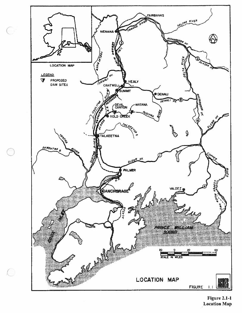
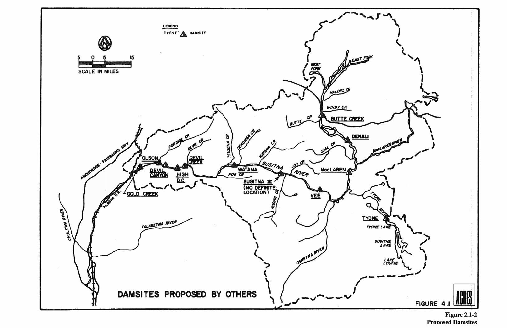

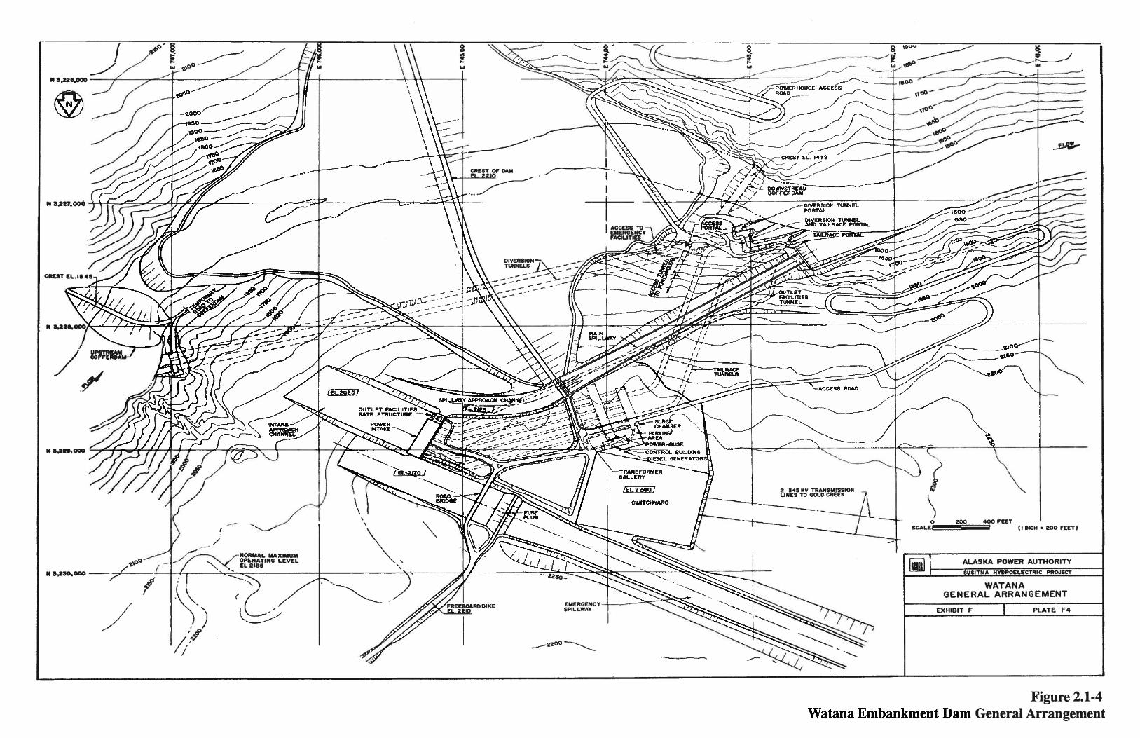
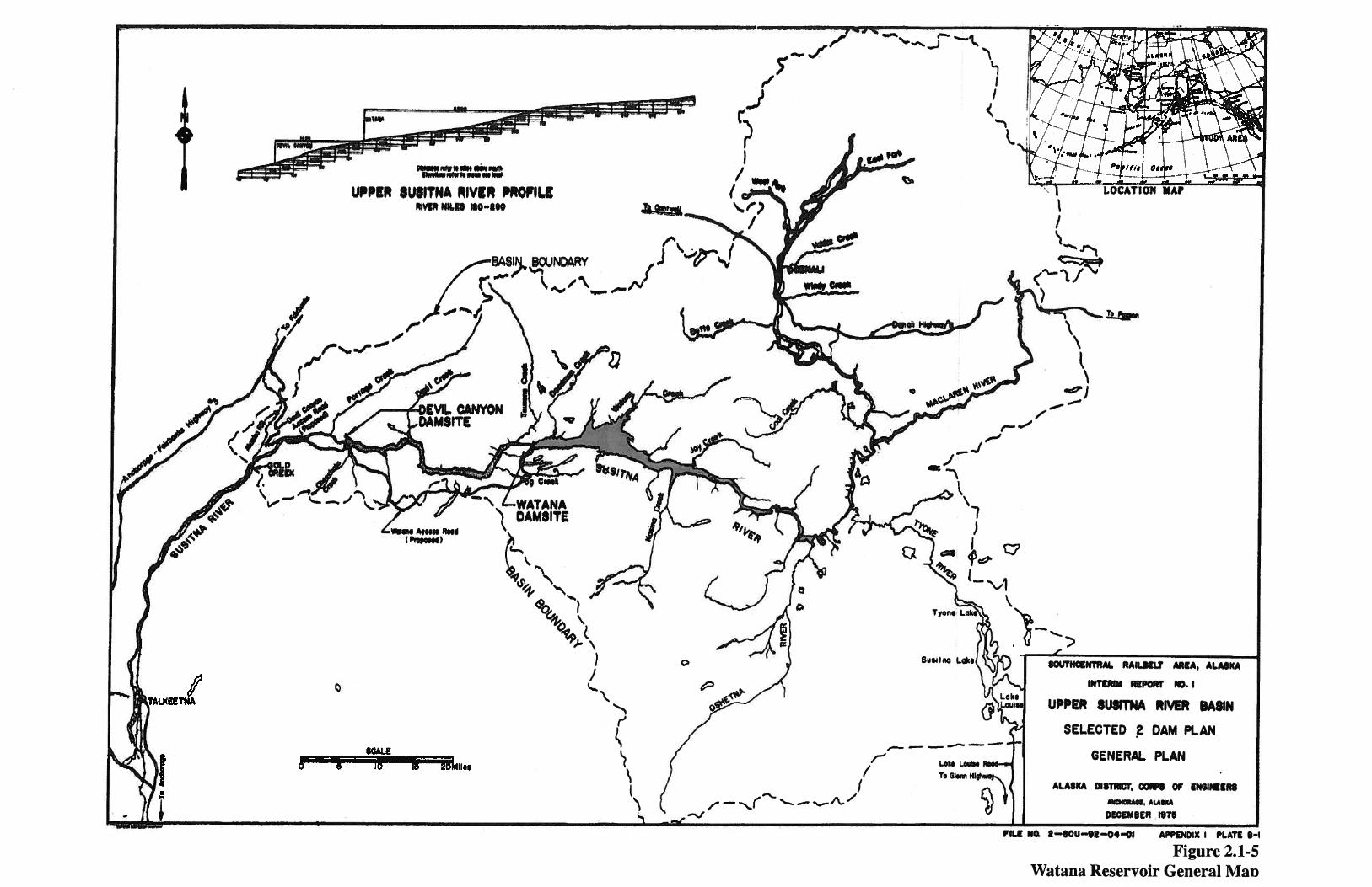

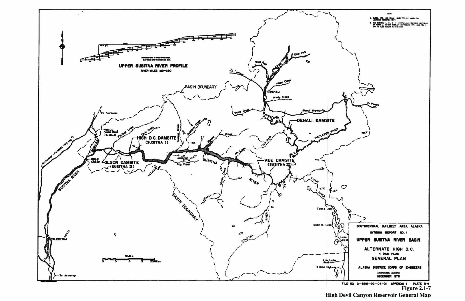

Figure 3.1-1Air Temperature
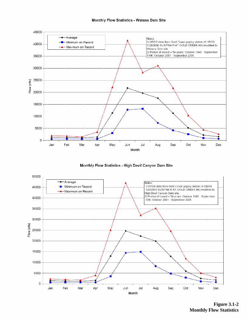
FMonthly Flow
Figure 3.1-2w Statistics

Figure 3.1-3Watana - Flood Frequency Analysis

Figure 3.1-4High Devil Canyon - Flood Frequency Analysis

FAverage A
Figure 3.1-5Annual Flow
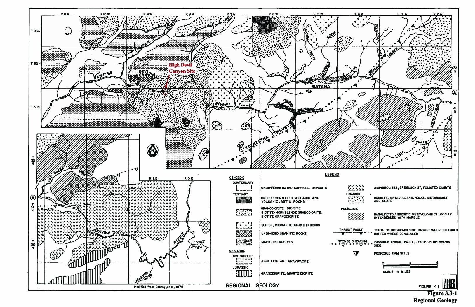
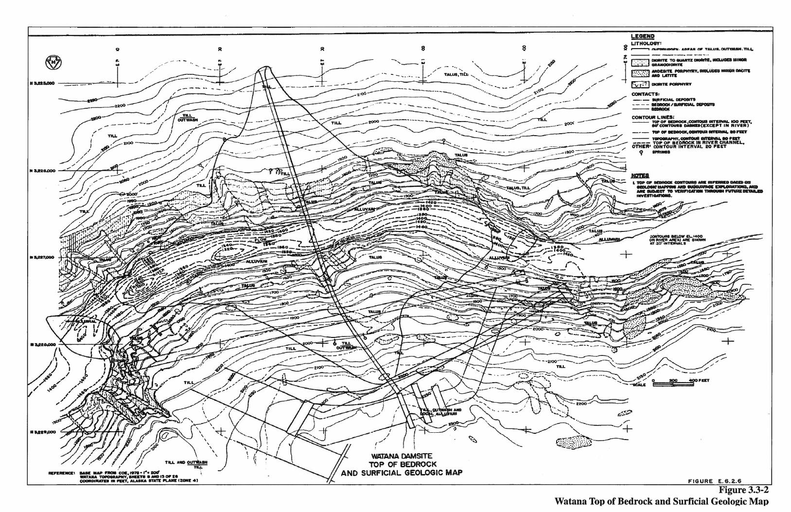
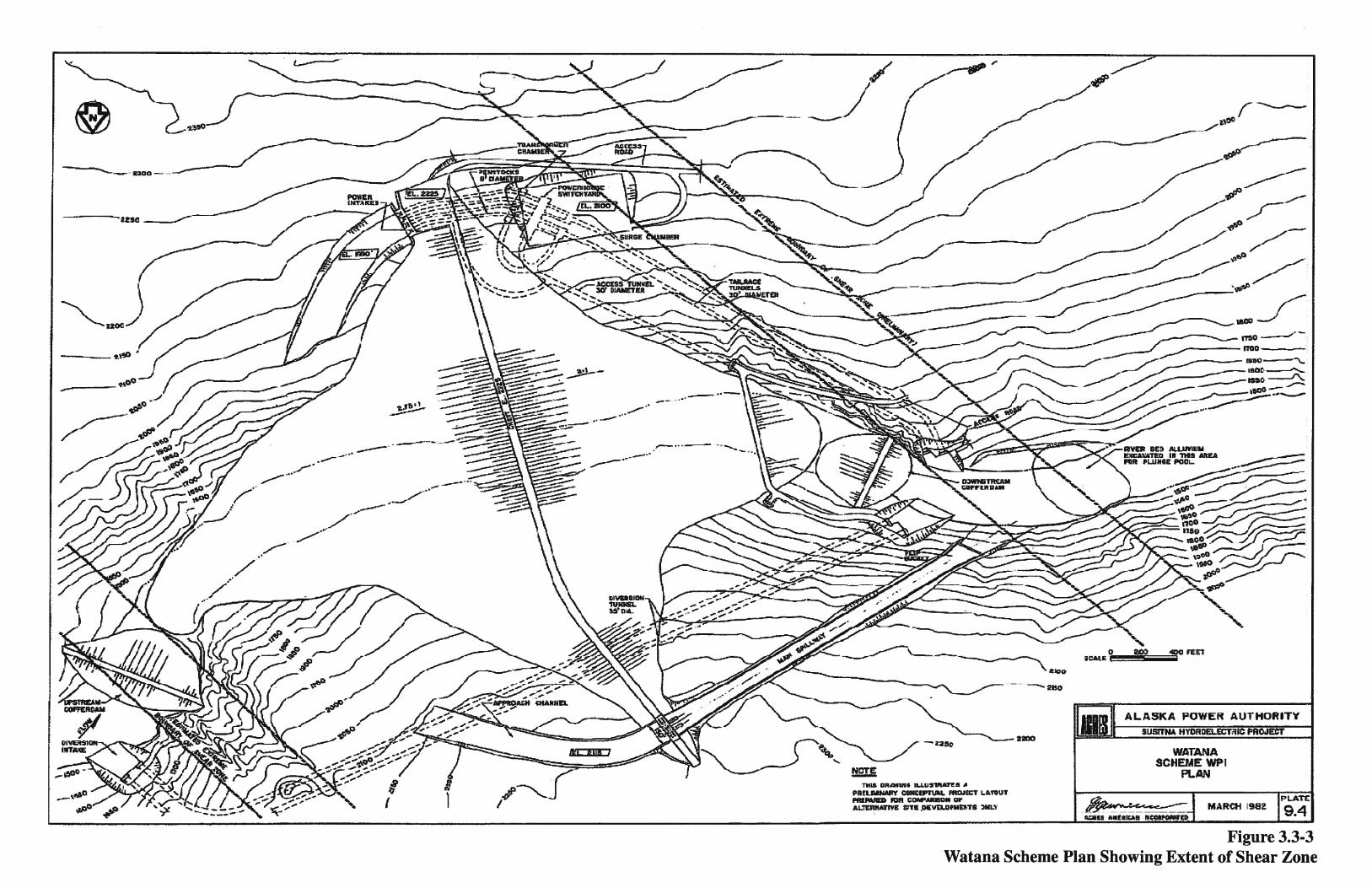


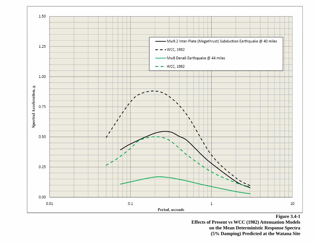
Figure 3.4-1Effects of Present vs WCC (1982) Attenuation Models
on the Mean Deterministic Response Spectra(5% Damping) Predicted at the Watana Site

Figure 3.4-284th Percentile Deterministic Response Spectra
(10% Damping) at the Watana Site for Active Earthquake Sources

Figure 3.4-3Deterministic Response Spectra
(10% Damping) at the Watana Site for the WCC (1982) Maximum Credible Detection Level (Random Local) Earthquake

Figure 3.4-4Recommended Deterministic Response 10 Spectra
(10 % Damping) for Conceptual Design of a RCC Dam at the Watana Site (M7.5 Wadati-Benioff Subduction Earthquake)
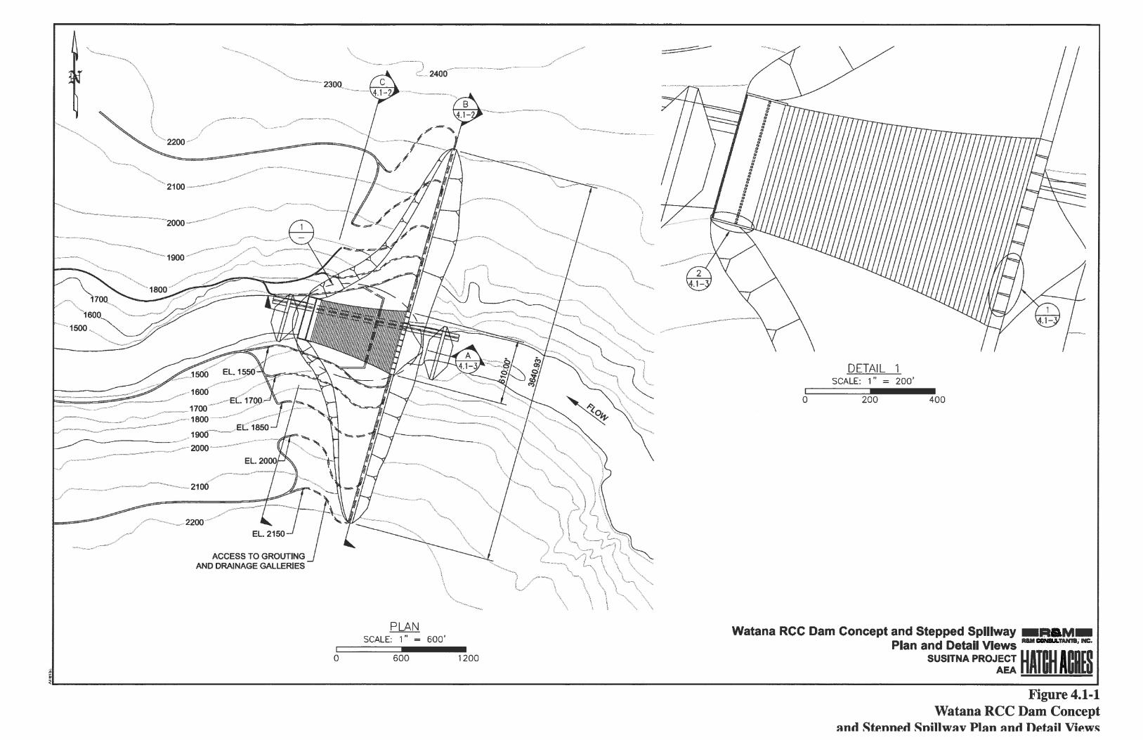


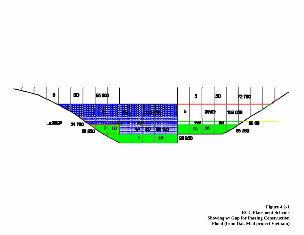
Fi 4 2 1Figure 4.2-1 RCC Placement Scheme
Showing w/ Gap for Passing Construction Flood (from Dak Mi 4 project Vietnam)


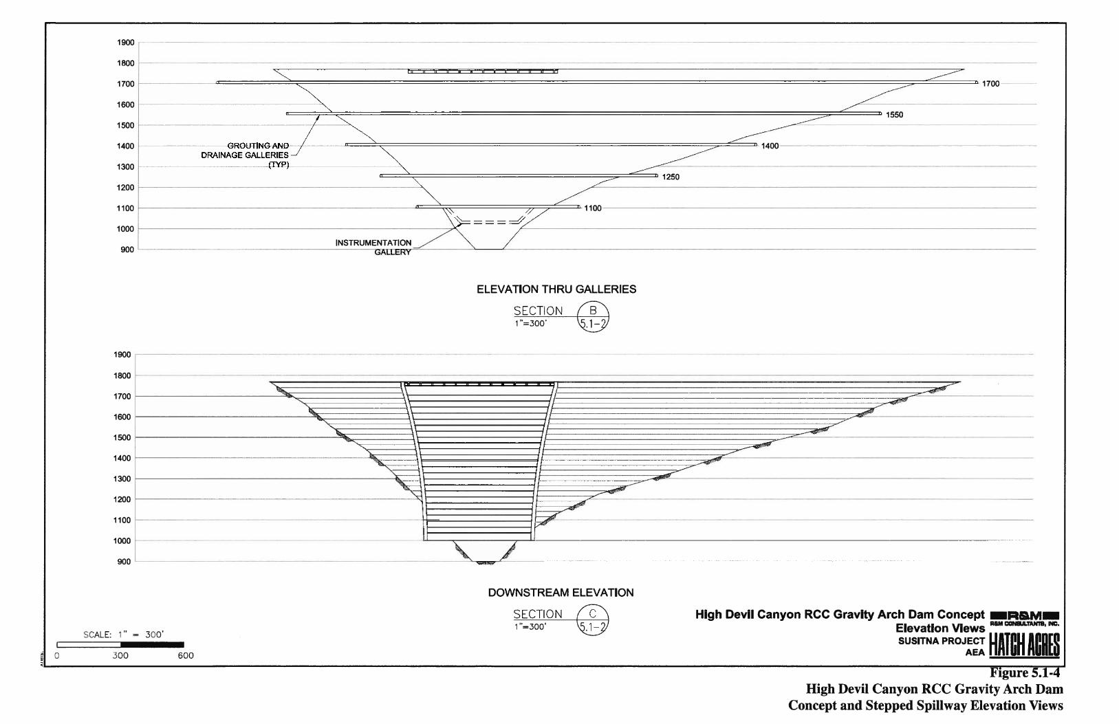

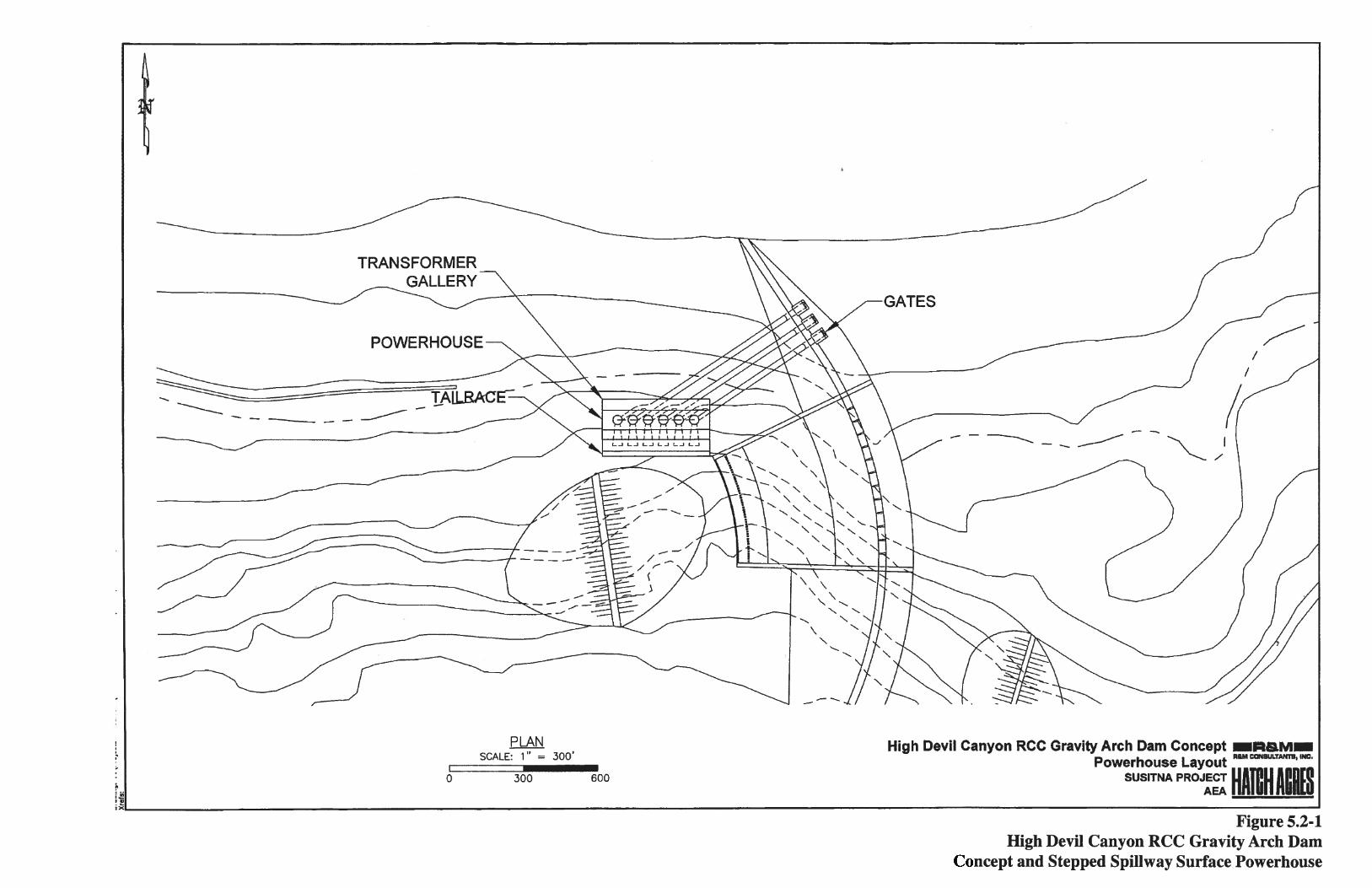

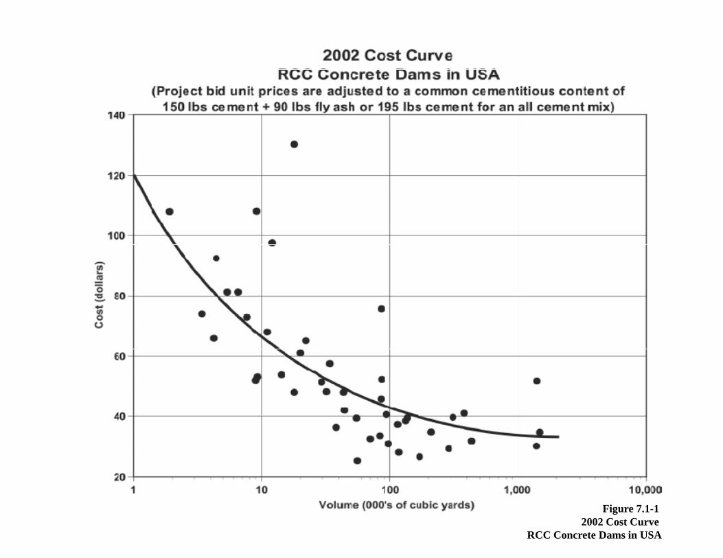
Figure 7.1-1 2002 Cost Curve
RCC Concrete Dams in USA


R&M Consultants - Hatch Acres AEA – Susitna RCC Dam Cost Evaluation
11/17/2009 FINAL
Appendix A –
Table of Property Ownership in 1980s
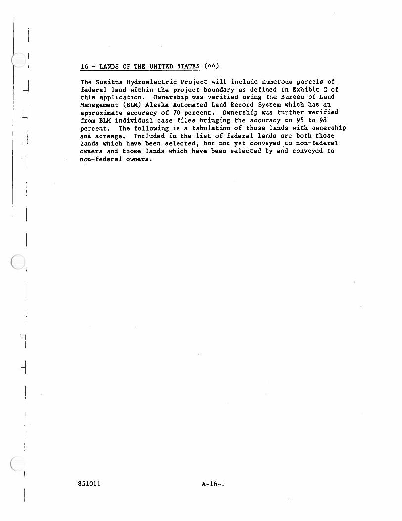
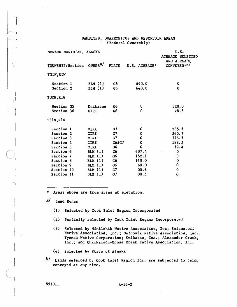

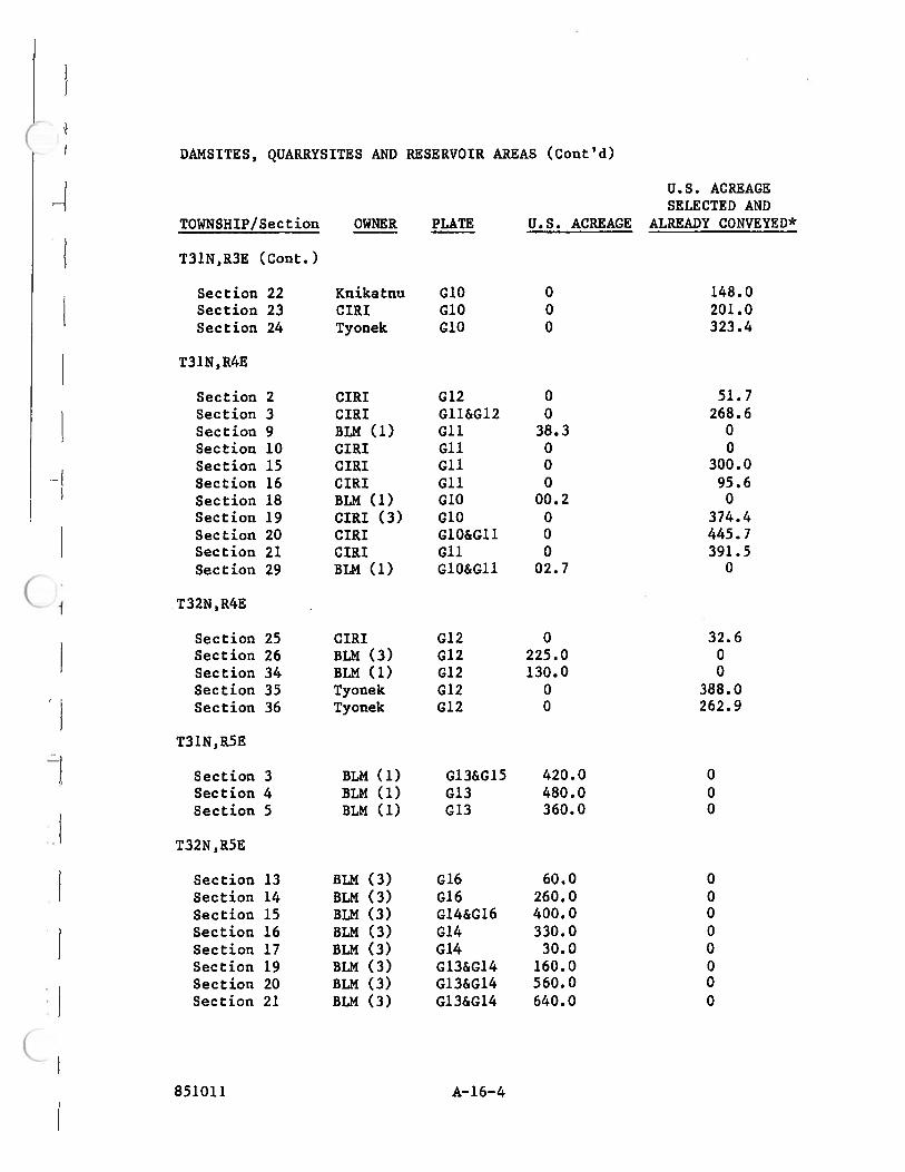


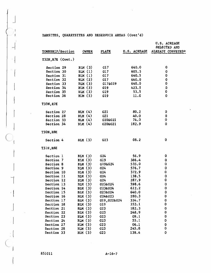

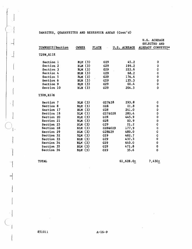
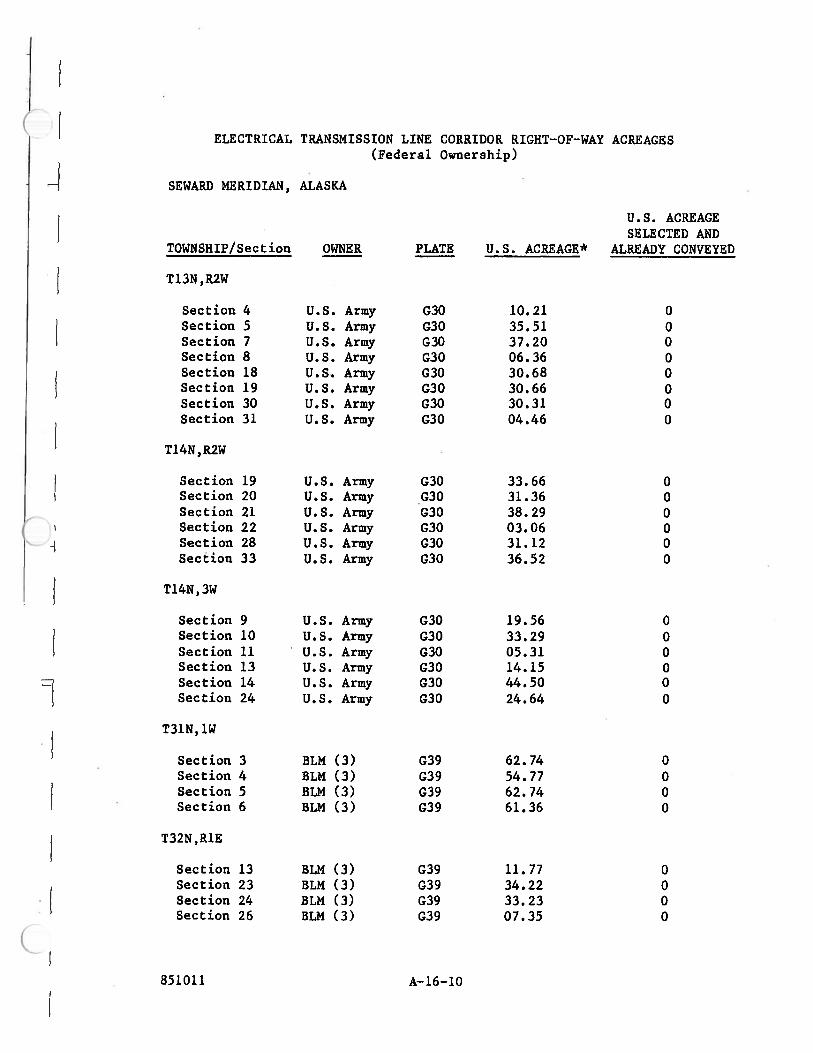
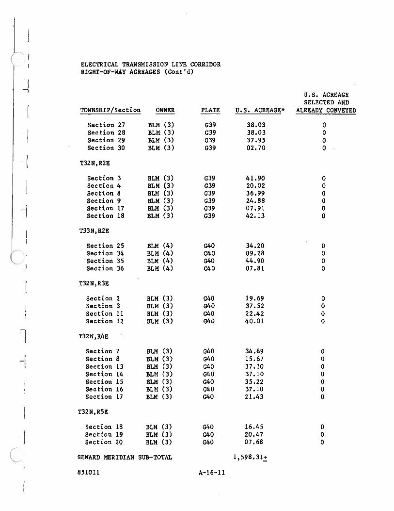


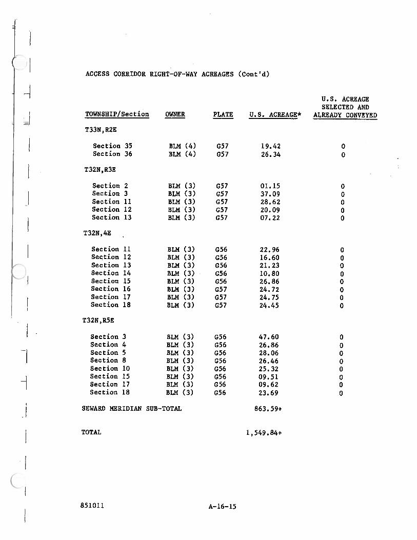

R&M Consultants - Hatch Acres AEA – Susitna RCC Dam Cost Evaluation
11/17/2009 FINAL
Appendix B –
Cost Estimate Summary Table

SUSITNA PROJECT - SUMMARY OF ESTIMATED CONSTRUCTION COST FOR RCC ALTERNATIVES AT
WATANA AND HIGH DEVIL CANYON
Line Item Name Full Watana RCC High Devil Canyon RCC
Total Estimated Const. Costs (Billions $) $6.6 $5.4
FERC Line # Line Item Name Full Watana RCC High Devil Canyon RCC
71A Engineering 4%, Env.2% & Regulatory 1% $ 341,700,000 $ 281,400,000
Subtotal 341,700,000$ 281,400,000$ Contingency (20%) 68,000,000$ 56,000,000$
Total 409,700,000$ 337,400,000$
330 Land and Land Rights 120,900,000$ 120,900,000$
331 Power Plant Structure Improvements 158,700,000$ 158,700,000$
332.1-.4 Reservoir, Dams and tunnels 2,306,874,000$ 1,803,156,000$
332.5-.9 Waterways 557,539,000$ 551,570,000$
333 Waterwheels, Turbines and Generators 487,000,000$ 487,000,000$
334 Accessory Electrical Equipment 57,100,000$ 57,100,000$
335 Misc Power Plant Equipment 32,450,000$ 32,450,000$
336 Roads, Rails and Air Facilities 583,500,000$ 489,700,000$
Subtotal 4,304,063,000$ 3,700,576,000$ Contingency (21.67%) 933,000,000$ 802,000,000$
Total 5,237,063,000$ 4,502,576,000$
350-390 Transmission Features 322,030,000$ 119,374,000$
Subtotal 322,030,000$ 119,374,000$ Contingency (20%) 64,000,000$ 24,000,000$
Total 386,030,000$ 143,374,000$
General Plant389 Land and Land Rights -$ -$ 390 Structures and Improvements -$ -$ 391 Office Furniture and Equipment -$ -$ 392 Transportation Equipment -$ -$ 393 Stores Equipment -$ -$ 394 Tools Shop and Garage Equipment -$ -$ 395 Laboratory Equipment -$ -$ 396 Power-Operated Equipment -$ -$ 397 Communications Equipment -$ -$ 398 Miscellaneous Equipment -$ -$ 399 Other Tangible Property 11,850,000$ 11,600,000$
Subtotal 11,850,000$ 11,600,000$ Contingency (20%) 2,000,000$ 2,000,000$
Total 13,850,000$ 13,600,000$
By: R&M/HAC Page 1 of 2 Summary Of RCC Alternatives

SUSITNA PROJECT - SUMMARY OF ESTIMATED CONSTRUCTION COST FOR RCC ALTERNATIVES AT
WATANA AND HIGH DEVIL CANYON
FERC Line # Line Item Name Full Watana RCC High Devil Canyon RCC
Indirect Costs61 Temporary Construction Facilities 0 -$ 62 Construction Equipment 0 -$ 63 Main Construction Camp 244,249,700$ 189,100,000$ 64 Labor Expense -$ -$ 65 Superintendence -$ -$ 66 Insurance -$ -$ 68 Mitigation -$ -$ 69 Fees -$ -$
Subtotal 244,249,700$ 189,100,000$ Contingency (20%) 49,000,000$ 38,000,000$
Total 293,249,700$ 227,100,000$
71B Construction Management (4%) 195,300,000$ 160,900,000$ 72 Legal Expenses -$ -$ 75 Taxes -$ -$ 76 Administrative & Gen. Expenses -$ -$ 77 Interest -$ -$ 80 Earnings/Expenses During Construction -$ -$
Subtotal 195,300,000$ 160,900,000$ Contingency (20%) 39,000,000$ 32,000,000$
Total 234,300,000$ 192,900,000$ Total Subtotal 5,419,192,700$ 4,462,950,000$
Total Contingency 1,155,000,000$ 954,000,000$ Total (Millions of Dollars) 6,600$ 5,400$
By: R&M/HAC Page 2 of 2 Summary Of RCC Alternatives
R&M Consultants - Hatch Acres AEA – Susitna RCC Dam Cost Evaluation
11/17/2009 FINAL
Appendix C –
Cost Estimate Detail – Full Watana RCC

FERC Line # Sub Categories Quantity Units Unit Price Line Price Total Notes / Remarks330 Land and Land Rights
0.1 Land 1 LS 120,870,000.00$ 120,870,000$ 0.2 Land Rights Included Above0.3 Misc Charges in Credit Above Included Above
120,900,000$
331 Powerplant Structure Improvements0.1 Powerhouse
0.11 Powerhouse and Draft Tube0.111 Excavation
Powerhouse Vault Rock 122,500 CY 90.12$ 11,040,000$ Draft Tube Rock 25,200 CY 90.12$ 2,271,000$
0.113 Surface Preparation/ GroutingPowerhouse 99,000 SF 3.33$ 330,000$ Draft Tube 76,500 SF 3.33$ 255,000$ Grout Curtain- Drill holes 43,800 LF 27.63$ 1,210,000$ Grout Curtain- Cement 17,500 CF 81.10$ 1,419,000$
0.114 Concrete and Shot CretePowerhouse Concrete 32,600 CY 692.87$ 22,588,000$ Powerhouse Concrete Overbreak 2,400 CY 447.21$ 1,073,000$ Powerhouse Reinforcing Steel 1,630 TON 2,858.29$ 4,659,000$ Powerhouse 4" Shotcrete 41,000 SF 10.14$ 416,000$ Draft Tube Concrete 12,000 CY 692.87$ 8,314,000$ Draft Tube Concrete Overbreak 2,500 CY 447.21$ 1,118,000$ Draft Tube Reinforcing Steel 990 TON 2,858.29$ 2,830,000$ Draft Tube 2" Shotcrete 6,100 SF 5.45$ 33,000$
0.115 Support and Anchors
Full Watana RCC (6 Turbines)Description
HDR/AEA Susitna Hydroelectric ProjectCost Estimates for 1982 quantities- Alternatives
By: Leanne Andruszkiewicz, EIT Date: 1/25/09Reviewed By: David Elwood, EIT Date: 1/25/09, Modified by Hatch Acres_mb_061109, R&M 11/16/09
Alternatives- 2008 Dollars
By: DTA with edits for RCC by R&M/Hatch Acres
Powerhouse Rockbolts 1" @ 25' Hy 970 EA 1,234.86$ 1,198,000$ Powerhouse Rockbolts 1" @ 15' 1,970 EA 735.81$ 1,450,000$ Powerhouse Steel Mesh 44,600 SF 5.81$ 259,000$ Powerhouse Steel Support 137 TON 12,671.94$ 1,736,000$ Draft Tube Rockbolts 1" @ 25' Hy 150 EA 1,234.86$ 185,000$ Draft Tube Rockbolts 1" @ 12' 390 EA 528.34$ 206,000$ Draft Tube Rockbolts 1" @ 9' 190 EA 432.12$ 82,000$ Draft Tube Steel Mesh 18,900 SF 6.55$ 124,000$
0.117 Holes (U/S of Powerhouse) 15,000 LF 51.32$ 770,000$ Holes (Powerhouse Crown) 28,500 LF 51.32$ 1,463,000$
0.118 Structural- Misc SteelworkPowerhouse and Draft Tube- Steel Crane Rails 1 LS 10,276,309.00$ 10,276,000$
0.119 Architectural- Powerhouse 1 LS 2,927,898.00$ 2,928,000$ y 0.11c Mechanical
Draft Tube Gates 4 SETS 427,880.00$ 1,712,000$ Draft Tube Gate Guides 6 SETS 202,680.00$ 1,216,000$ Draft Tube Crane 1 LS 1,140,000.00$ 1,140,000$
0.12 Access Tunnels and Portals 0.121 Excavation
Main Tunnel 50,250 CY 97.45$ 4,897,000$ Transformer Gallery Tunnel 17,750 CY 97.45$ 1,730,000$ Grouting Gallery Tunnel 1,900 CY 396.04$ 752,000$ Surge Chamber Access Tunnel 7,250 CY 145.22$ 1,053,000$ Penstock Access Tunnel 61,500 CY 145.22$ 8,931,000$ Penstock Elbow Access Tunnel 15,000 CY 145.22$ 2,178,000$ Access Shaft Tunnel 1,300 CY 145.22$ 189,000$
By: DTA edited for RCC by R&M/HAC Page 1 of 16 Alternative: Full Watana RCC

FERC Line # Sub Categories Quantity Units Unit Price Line Price Total Notes / RemarksFull Watana RCC (6 Turbines)
Description
HDR/AEA Susitna Hydroelectric ProjectCost Estimates for 1982 quantities- Alternatives
By: Leanne Andruszkiewicz, EIT Date: 1/25/09Reviewed By: David Elwood, EIT Date: 1/25/09, Modified by Hatch Acres_mb_061109, R&M 11/16/09
Alternatives- 2008 Dollars
By: DTA with edits for RCC by R&M/Hatch Acres
Connector Tunnel 1,900 CY 379.26$ 721,000$ Portals Overburden 6,000 CY 17.14$ 103,000$ Portals Rock 3,000 CY 49.31$ 148,000$
0.123 Surface Preparation Main Tunnel Slab 53,100 SF 2.21$ 117,000$ Penstock Access Slab 65,200 SF 2.21$ 144,000$ Horizontal Portal 200 SF 2.30$ -$ Inclined Portal 2,100 SF 3.33$ 7,000$
0.124 Concrete and Shot CreteMain Portal
Concrete Slab 30 CY 406.27$ 12,000$ Concrete Walls 570 CY 406.27$ 232,000$ Concrete Overbreak 50 CY 368.48$ 18,000$ Reinforcing Steel 40 TON 2,887.51$ 116,000$
TunnelsConcrete Slab Main Tunnel 1,950 CY 503.90$ 983,000$ Concrete Plugs Penstock Elbow ACC 15,000 CY 755.86$ 11,338,000$ Concrete Overbreak Main Tunnel 6" 1,000 CY 346.43$ 346,000$ Reinforcing Steel 70 TON 2,887.51$ 202,000$ 2 " Shotcrete Main Tunnel 20,100 SF 5.26$ 106,000$ 2 " Shotcrete Transformer Gal 7,100 SF 5.26$ 37,000$ 2 " Shotcrete Surge Chamber Acc 3,900 SF 5.26$ 21,000$ 2 " Shotcrete Penstock Access 24,700 SF 5.26$ 130,000$ 2 " Shotcrete Penstock Elbow Acc 7,100 SF 5.26$ 37,000$ 2 " Shotcrete Access Shaft 300 SF 5.26$ 2,000$ 2 " Shotcrete Grout Gallery 800 SF 5.26$ 4,000$ 2 " Shotcrete Connector Tunnel 800 SF 5.26$ 4,000$
0.125 Support and AnchorsMain Tunnel
Rockbolts 1" @12' 1,200 EA 528.34$ 634,000$ Rockbolts 1" @ 9' 250 EA 432.12$ 108,000$ Steel Mesh 63,000 SF 6.37$ 401,000$ Steel Support 66 TON 12,801.49$ 845,000$
Main Tunnel PortalRockbolts 1" @15' 50 EA 735.79$ 37,000$
Transformer Gallery Tunnel Rockbolts 1" @12' 410 EA 528.34$ 217,000$ Rockbolts 1" @ 9' 70 EA 432.12$ 30,000$ Steel Mesh 22,500 SF 5.89$ 133,000$ Steel Support 24 TON 12,801.49$ 307,000$
Grouting Gallery TunnelRockbolts 3/4" @ 6' 160 EA 327.15$ 52,000$ Steel Mesh 160 SF 6.37$ 1,000$ Steel Support 2 TON 12,801.49$ 26,000$
Surge Chamber Access TunnelRockbolts 1" @12' 230 EA 528.34$ 122,000$ Rockbolts 1" @ 9' 50 EA 432.12$ 22,000$ Steel Mesh 12,050 SF 6.37$ 77,000$ Steel Support 14 TON 12,801.49$ 179,000$
Penstock Access TunnelRockbolts 1" @12' 1,430 EA 528.34$ 756,000$ Rockbolts 1" @ 9' 240 EA 432.12$ 104,000$ Steel Mesh 77,500 SF 6.37$ 494,000$
By: DTA edited for RCC by R&M/HAC Page 2 of 16 Alternative: Full Watana RCC

FERC Line # Sub Categories Quantity Units Unit Price Line Price Total Notes / RemarksFull Watana RCC (6 Turbines)
Description
HDR/AEA Susitna Hydroelectric ProjectCost Estimates for 1982 quantities- Alternatives
By: Leanne Andruszkiewicz, EIT Date: 1/25/09Reviewed By: David Elwood, EIT Date: 1/25/09, Modified by Hatch Acres_mb_061109, R&M 11/16/09
Alternatives- 2008 Dollars
By: DTA with edits for RCC by R&M/Hatch Acres
Steel Support 58 TON 12,801.49$ 742,000$ Penstock Elbow Access Tunnel
Rockbolts 1" @12' 420 EA 528.34$ 222,000$ Rockbolts 1" @ 9' 120 EA 432.12$ 52,000$ Steel Mesh 22,500 SF 6.37$ 143,000$ Steel Support 30 TON 12,801.49$ 384,000$
Access Shaft TunnelRockbolts 1" @12' 20 EA 528.34$ 11,000$ Rockbolts 1" @ 9' 20 EA 432.12$ 9,000$ Steel Mesh 930 SF 6.37$ 6,000$ Steel Support 8 TON 12,801.49$ 102,000$
Connector TunnelRockbolts 3/4" @ 6' 160 EA 327.15$ 52,000$ Steel Mesh 160 SF 6.37$ 1,000$ Steel Support 2 TON 12,801.49$ 26,000$
0.129 Architectural- Main Portal Doors 2 SETS 158,371.90$ 317,000$ 0.12c Mechanical Ventilation System Included in (63.81 and 63.82)
0.13 Access Shaft0.131 Excavation Rock 13,700 CY 227.67$ 3,119,000$ 0.133 Surface Preparation Shaft 64,000 SF 3.33$ 213,000$ 0.134 Concrete and Shot Crete
Concrete Lining 3,350 CY 944.82$ 3,165,000$ Concrete Overbreak 6" 1,220 CY 551.14$ 672,000$
0.135 Support and Anchors - Rockbolts 3/4" @ 6' 1,050 EA 327.15$ 344,000$ 0.138 Structural Misc Steelwork 50 TON 7,395.00$ 370,000$ 0.139 Architectural- control Building 0.13c Mechanical Elevators 1 LS 2,368,815.00$ 2,369,000$
0.14 Fire Protection Head Tank0.141 Excavation 1,150 CY 588.80$ 677,000$ 0.143 Surface Preparation 2,800 SF 2.30$ 6,000$ 0.144 Concrete & Shotcrete
Concrete 250 CY 963.72$ 241,000$ Concrete Overbreak 6" 45 CY 406.27$ 18,000$ Reinforcing Steel 10 TON 2,858.29$ 29,000$
0.145 Support and AnchorsRockbolts 1" @12' 25 EA 528.34$ 13,000$ Rockbolts 1" @ 9' 10 EA 432.12$ 4,000$ Steel Mesh 1,200 SF 6.30$ 8,000$ Steel Support 2 TON 12,671.95$ 25,000$
0.148 Misc Steelwork 1 LS 73,297.50$ 73,000$ 0.14c Mechanical Piping/Valves (Included in 335.12)
0.15 Bus Tunnels (totals for 3 Bus Tunnels)0.151 Excavation
Rock Horizontal 2,700 CY 213.70$ 577,000$ Rock Inclined 1,300 CY 601.04$ 781,000$
0.153 Surface Preparation- Tunnels 7,100 SF 3.33$ 24,000$ 0.154 Concrete and Shotcrete
Concrete Slab 350 CY 818.84$ 287,000$ Concrete Overbreak 12" 250 CY 472.41$ 118,000$ Reinforcing Steel 18 TON 2,858.29$ 51,000$ 2" Shotcrete 2,200 SF 5.26$ 12,000$
0.155 Supports and Anchors
By: DTA edited for RCC by R&M/HAC Page 3 of 16 Alternative: Full Watana RCC

FERC Line # Sub Categories Quantity Units Unit Price Line Price Total Notes / RemarksFull Watana RCC (6 Turbines)
Description
HDR/AEA Susitna Hydroelectric ProjectCost Estimates for 1982 quantities- Alternatives
By: Leanne Andruszkiewicz, EIT Date: 1/25/09Reviewed By: David Elwood, EIT Date: 1/25/09, Modified by Hatch Acres_mb_061109, R&M 11/16/09
Alternatives- 2008 Dollars
By: DTA with edits for RCC by R&M/Hatch Acres
Rockbolts 1" @ 25' 60 EA 1,234.86$ 74,000$ Rockbolts 1" @ 12' 140 EA 528.34$ 74,000$ Rockbolts 1" @ 9' 50 EA 432.12$ 22,000$ Steel Mesh 6,800 SF 6.30$ 43,000$ Steel Support 11 TON 12,671.94$ 139,000$
0.16 Transformer Gallery Tunnel0.161 Excavation- Rock 26,800 CY 87.44$ 2,343,000$ 0.163 Surface Preparation 24,600 SF 2.30$ 57,000$ 0.164 Concrete and Shotcrete
Concrete Base Slab 2,400 CY 1,228.27$ 2,948,000$ Concrete Overbreak 12"H/6"V 770 CY 377.93$ 291,000$ Reinforcing Steel 120 TON 2,858.29$ 343,000$
0.165 Support and AnchorsRockbolts 1" @ 25' 600 EA 1,234.86$ 741,000$ Rockbolts 1" @ 15' 270 EA 735.81$ 199,000$ Steel Mesh 20,700 SF 5.81$ 120,000$ Steel Support 29 TON 12,671.94$ 367,000$
0.167 Drainage Holes 8,300 LF 47.95$ 398,000$ 0.17 Cable Shafts
0.171 Excavation Rock 3,400 CY 601.04$ 2,044,000$ 0.173 Surface Preparation Shafts 41,400 SF 3.33$ 138,000$ 0.174 Concrete and Shotcrete
Concrete Lining 1,040 CY 1,763.66$ 1,834,000$ Concrete Overbreak 6" 800 CY 881.83$ 705,000$
0.175 Supports and Anchors- Rockbolts 3/4" @ 6' 650 EA 327.15$ 213,000$ 0.178 Structural Misc Steelwork 18 TON 15,602.00$ 281,000$ 0.179 Architectural- Enclosures 1 LS 199,317.00$ 199,000$ 0.17c Mechanical Hoist 2 EA 476,960.00$ 954,000$
0.18 Dewatering (during Construction)0.181 Dewatering (Power Facilities) 1 LS 1,336,798.50$ 1,337,000$
0.19 Instrumentation0.191 Instrumentation 1 LS 1,714,813.50$ 1,715,000$
0.2 Misc Buildings (Control Buildings) 1 LS 4,433,085.00$ 4,433,000$ 0.3 Permanent Town (included in 63.5)
158,700,000$ 332 Reservoir, Dams and Waterways
0.1 Reservoir0.11 Reservoir Clearing 37,500 ACRE 3,005.85$ 112,719,000$ (same as embankment dam)
0.2 Diversion Schemes /Cofferdams0.21 Diversion Schemes
0.211 ExcavationRock 287,800 CY 50.18$ 14,442,000$ (03.31.311 Rock Waste)Soil 432,000 CY 11.53$ 4,981,000$ (03.31.311 Overburden above)
0.212 Water ConveyanceDiversion Pipes
Steel Pipe 9,997,000 LB 5.00$ 49,985,000$ use unit price from 0.818 rounded up to $5/lbConcrete Pipe Support (coventional concrete) 18,400 CY 544.85$ 10,025,000$ use unit price from 0.614Reinforcing Steel 400 TON 2,887.51$ 1,155,000$ use unit price from 0.614
Emergency Release ChambersConcrete Plug 15,300 CY 755.86$ 11,565,000$ 4" Shotcrete 2,790 SF 10.13$ 28,000$ Use same concrete plug and gate system
0.21c Mechanical as in embankment dam shemeUpstream Lower Gates
Gate Equipment 2 EA 5,073,120.00$ 10,146,000$
By: DTA edited for RCC by R&M/HAC Page 4 of 16 Alternative: Full Watana RCC
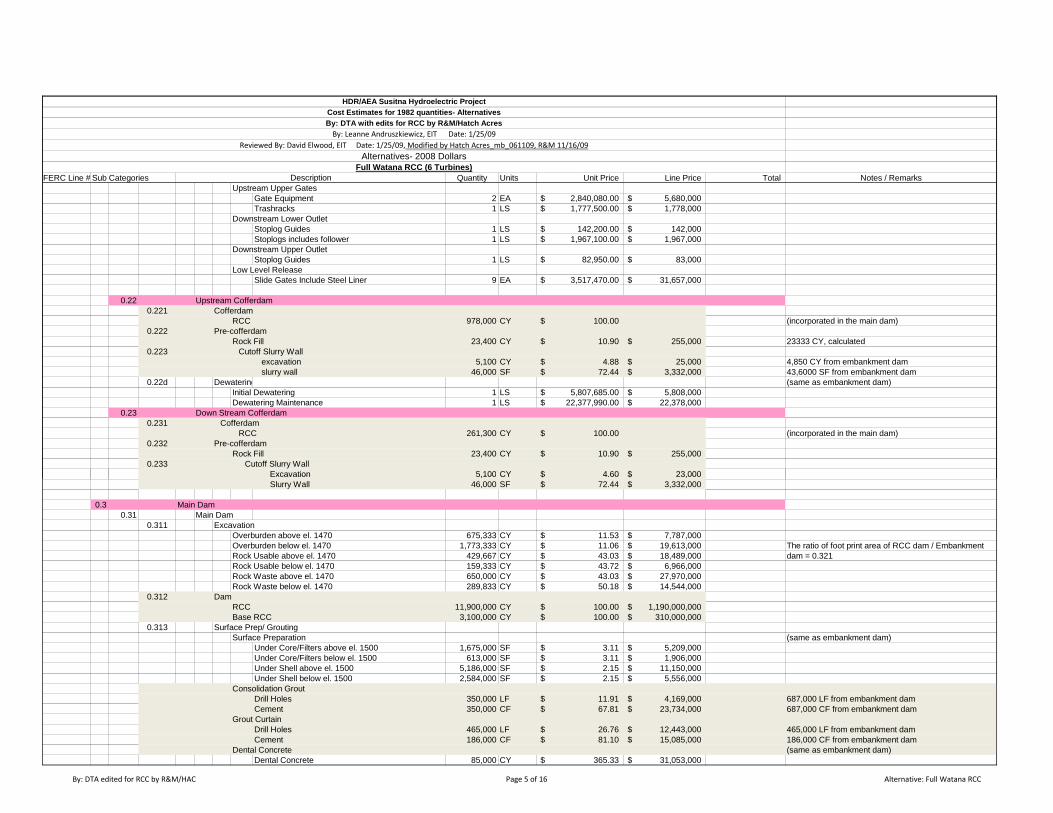
FERC Line # Sub Categories Quantity Units Unit Price Line Price Total Notes / RemarksFull Watana RCC (6 Turbines)
Description
HDR/AEA Susitna Hydroelectric ProjectCost Estimates for 1982 quantities- Alternatives
By: Leanne Andruszkiewicz, EIT Date: 1/25/09Reviewed By: David Elwood, EIT Date: 1/25/09, Modified by Hatch Acres_mb_061109, R&M 11/16/09
Alternatives- 2008 Dollars
By: DTA with edits for RCC by R&M/Hatch Acres
Upstream Upper GatesGate Equipment 2 EA 2,840,080.00$ 5,680,000$ Trashracks 1 LS 1,777,500.00$ 1,778,000$
Downstream Lower Outlet Stoplog Guides 1 LS 142,200.00$ 142,000$ Stoplogs includes follower 1 LS 1,967,100.00$ 1,967,000$
Downstream Upper Outlet Stoplog Guides 1 LS 82,950.00$ 83,000$
Low Level ReleaseSlide Gates Include Steel Liner 9 EA 3,517,470.00$ 31,657,000$
0.22 Upstream Cofferdam 0.221 Cofferdam
RCC 978,000 CY 100.00$ (incorporated in the main dam)0.222 Pre-cofferdam
Rock Fill 23,400 CY 10.90$ 255,000$ 23333 CY, calculated0.223 Cutoff Slurry Wall
excavation 5,100 CY 4.88$ 25,000$ 4,850 CY from embankment dam slurry wall 46,000 SF 72.44$ 3,332,000$ 43,6000 SF from embankment dam
0.22d Dewatering (same as embankment dam)Initial Dewatering 1 LS 5,807,685.00$ 5,808,000$ Dewatering Maintenance 1 LS 22,377,990.00$ 22,378,000$
0.23 Down Stream Cofferdam0.231 Cofferdam
RCC 261,300 CY 100.00$ (incorporated in the main dam)0.232 Pre-cofferdam
Rock Fill 23,400 CY 10.90$ 255,000$ 0.233 Cutoff Slurry Wall
Excavation 5,100 CY 4.60$ 23,000$ Excavation 5,100 CY 4.60$ 23,000$ Slurry Wall 46,000 SF 72.44$ 3,332,000$
0.3 Main Dam0.31 Main Dam
0.311 ExcavationOverburden above el. 1470 675,333 CY 11.53$ 7,787,000$ Overburden below el. 1470 1,773,333 CY 11.06$ 19,613,000$ The ratio of foot print area of RCC dam / Embankment Rock Usable above el. 1470 429,667 CY 43.03$ 18,489,000$ dam = 0.321Rock Usable below el. 1470 159,333 CY 43.72$ 6,966,000$ Rock Waste above el. 1470 650,000 CY 43.03$ 27,970,000$ Rock Waste below el. 1470 289,833 CY 50.18$ 14,544,000$
0.312 DamRCC 11,900,000 CY 100.00$ 1,190,000,000$ Base RCC 3,100,000 CY 100.00$ 310,000,000$
0.313 Surface Prep/ GroutingSurface Preparation (same as embankment dam)
Under Core/Filters above el. 1500 1,675,000 SF 3.11$ 5,209,000$ Under Core/Filters below el. 1500 613,000 SF 3.11$ 1,906,000$
Under Shell above el. 1500 5,186,000 SF 2.15$ 11,150,000$ Under Shell below el. 1500 2,584,000 SF 2.15$ 5,556,000$
Consolidation GroutDrill Holes 350,000 LF 11.91$ 4,169,000$ 687,000 LF from embankment damCement 350,000 CF 67.81$ 23,734,000$ 687,000 CF from embankment dam
Grout CurtainDrill Holes 465,000 LF 26.76$ 12,443,000$ 465,000 LF from embankment damCement 186,000 CF 81.10$ 15,085,000$ 186,000 CF from embankment dam
Dental Concrete (same as embankment dam)Dental Concrete 85,000 CY 365.33$ 31,053,000$
By: DTA edited for RCC by R&M/HAC Page 5 of 16 Alternative: Full Watana RCC

FERC Line # Sub Categories Quantity Units Unit Price Line Price Total Notes / RemarksFull Watana RCC (6 Turbines)
Description
HDR/AEA Susitna Hydroelectric ProjectCost Estimates for 1982 quantities- Alternatives
By: Leanne Andruszkiewicz, EIT Date: 1/25/09Reviewed By: David Elwood, EIT Date: 1/25/09, Modified by Hatch Acres_mb_061109, R&M 11/16/09
Alternatives- 2008 Dollars
By: DTA with edits for RCC by R&M/Hatch Acres
0.317 DrainageHoles 136,000 LF 51.32$ 6,980,000$
0.318 BridgePrecast Bridge Beams 25,500 CY 544.85$ 13,894,000$ Unit price from item 0.614Concrete Road Deck 5,400 CY 544.85$ 2,942,000$ Unit price from item 0.614Piers 500 CY 544.85$ 272,000$ Unit price from item 0.614
0.32 Grout Galleries/Portals (3 portals , multiply by 3)0.321 Excavation
Tunnels/ Shafts- Core AreaRock Horizontal 77,400 CY 394.80$ 30,558,000$ 13000 CY
Portals Overburden Rock 10,000 CY 17.16$ 172,000$ 3600 CYRock 3,000 CY 49.16$ 147,000$ 1000 CY
0.323 Surface PreparationPortals
Horizontal 100 SF 2.30$ -$ 30 SFInclined 500 SF 3.33$ 2,000$ 200 SF
0.324 Concrete and ShotcreteTunnels- Core Area
Concrete Plugs 1,000 CY 428.32$ 428,000$ Concrete Slab 2,300 CY 944.82$ 2,173,000$ Concrete Overbreak 6" 1,150 CY 755.86$ 869,000$ Reinforcing Steel 80 TON 2,887.51$ 231,000$ 2" Shotcrete 15,000 SF 5.26$ 79,000$
Tunnels-AccessConcrete Slab 1,600 CY 944.82$ 1,512,000$ Concrete Overbreak 6" 800 CY 755.86$ 605,000$ Reinforcing Steel 60 TON 2,887.51$ 173,000$Reinforcing Steel 60 TON 2,887.51$ 173,000$ 2" Shotcrete 5,400 SF 5.26$ 28,000$
Shafts2" Shotcrete 5,000 SF 5.26$ 26,000$
Portals Concrete 60 CY 406.36$ 24,000$ 20 CYReinforcing Steel 6 TON 2,887.51$ 17,000$ 2 TON
0.325 Support and AnchorsTunnels- Core Area
Rockbolts 3/4" @6' 1,800 EA 327.15$ 589,000$ Steel Mesh 3,000 SF 5.37$ 16,000$ Steel Support 20 TON 12,801.49$ 256,000$
Tunnels- AccessRockbolts 3/4" @6' 1,200 EA 327.15$ 393,000$ Steel Mesh 1,100 SF 5.37$ 6,000$ Steel Support 20 TON 12,801.49$ 256,000$
Shafts Rockbolts 3/4" @6' 350 EA 327.15$ 115,000$ Steel Mesh 1,000 SF 5.37$ 5,000$
Portals Rockbolts 1" @15' 30 EA 735.81$ 22,000$
0.329 Architectural Portal DoorsPortal Doors 2 EA 42,123.66$ 84,000$
0.33 Instrumentation 0.331 Instrumentation 1 LS 10,821,538.50$ 10,822,000$ This cost is taken as 50% of embankment dam
0.4 Relict Channel (same as embankment dam)0.41 Shore Protection
0.411 Excavation Overburden Stripping 2' thick 2,200 CY 11.56$ 25,000$
By: DTA edited for RCC by R&M/HAC Page 6 of 16 Alternative: Full Watana RCC

FERC Line # Sub Categories Quantity Units Unit Price Line Price Total Notes / RemarksFull Watana RCC (6 Turbines)
Description
HDR/AEA Susitna Hydroelectric ProjectCost Estimates for 1982 quantities- Alternatives
By: Leanne Andruszkiewicz, EIT Date: 1/25/09Reviewed By: David Elwood, EIT Date: 1/25/09, Modified by Hatch Acres_mb_061109, R&M 11/16/09
Alternatives- 2008 Dollars
By: DTA with edits for RCC by R&M/Hatch Acres
0.412 Fill Dump and Spread
Filter Material - 2' layer 2,200 CY 31.93$ 70,000$ Rock Spalls/ Rip Rap- 3' Ave 3,300 CY 9.86$ 33,000$
Shore Protection Rip Rap 24,000 CY 24.26$ 582,000$ Waste Rock 24,000 CY 22.78$ 547,000$
0.44 Channel Filter Blanket0.442 Fill
Coarse Filter 2,900,000 CY 33.85$ 98,165,000$ Fine Filter 2,180,000 CY 43.65$ 95,157,000$ Rip Rap 182,000 CY 24.26$ 4,415,000$
0.443 Surface preparationFoundation Prep
Clearing and Grubbing 460 ACRE 3,963.11$ 1,823,000$ Excavation 2,236,000 CY 15.62$ 34,926,000$ 2,306,874,000$
0.5 Outlet Facilities 0.51 Outlet Facilities- (Intake Civil Work Include in Power Intake ) (same as embankment dam)
0.511 ExcavationInlet (Included in 332.611)Outlet (Included in 332.521)Tunnels
Rock Horizontal 83,000 CY 103.00$ 8,549,000$ Rock Inclined 9,000 CY 183.49$ 1,651,000$
0.513 Surface Preparation/ Grouting Inlet (Included in 332.613)Outlet (Included in 332.523)Tunnels 323,500 SF 2.30$ 744,000$ Contact Grouting 1 LS 569,428.05$ 569,000$Contact Grouting 1 LS 569,428.05$ 569,000$
0.514 Concrete and Shotcrete Inlet (Included in 332.614)Outlet (Included in 332.524)Tunnels
Concrete Lining 27,200 CY 944.82$ 25,699,000$ Concrete Overbreak 6" 6,200 CY 440.92$ 2,734,000$ 2" Shotcrete 12,000 SF 5.26$ 63,000$ 3" Shotcrete 19,400 SF 7.69$ 149,000$
0.515 Support and AnchorsInlet (Included in 332.615)Outlet (Included in 332.525)Tunnels
Rock Bolts 1" @6' 2,400 EA 327.15$ 785,000$ Steel Mesh 94,500 SF 6.37$ 602,000$
0.51c Mechanical Inlet
Trash Racks/Guides 1 LS 1,540,500.00$ 1,541,000$ Gate Equipment 2 EA 3,317,040.00$ 6,634,000$ Stoplog Guides 2 SETS 213,940.00$ 428,000$
OutletFixed Cone Valves 6 +1 Spare 1 LS 4,500,630.00$ 4,501,000$ Ring Follower Gates 6 EA 1,936,494.80$ 11,619,000$ Steel Manifold Liner 1,950 TON 8,952.53$ 17,457,000$ Misc Mechanical Equipment 1 LS 948,000.00$ 948,000$ Misc Electrical Systems 1 LS 237,000.00$ 237,000$
0.52 Main (Chute ) Spillway (Includes Civil Works for Outlet Facilities)0.522 Stepped Spillway
Conventional concrete 89,000 CY 544.85$ 48,492,000$ 89,000 CY, calculated, unit price from item 0.614
By: DTA edited for RCC by R&M/HAC Page 7 of 16 Alternative: Full Watana RCC
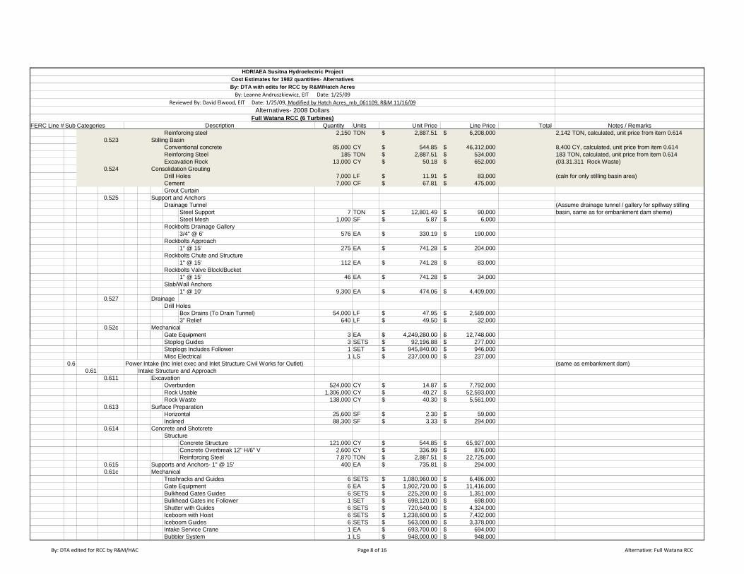
FERC Line # Sub Categories Quantity Units Unit Price Line Price Total Notes / RemarksFull Watana RCC (6 Turbines)
Description
HDR/AEA Susitna Hydroelectric ProjectCost Estimates for 1982 quantities- Alternatives
By: Leanne Andruszkiewicz, EIT Date: 1/25/09Reviewed By: David Elwood, EIT Date: 1/25/09, Modified by Hatch Acres_mb_061109, R&M 11/16/09
Alternatives- 2008 Dollars
By: DTA with edits for RCC by R&M/Hatch Acres
Reinforcing steel 2,150 TON 2,887.51$ 6,208,000$ 2,142 TON, calculated, unit price from item 0.6140.523 Stilling Basin
Conventional concrete 85,000 CY 544.85$ 46,312,000$ 8,400 CY, calculated, unit price from item 0.614Reinforcing Steel 185 TON 2,887.51$ 534,000$ 183 TON, calculated, unit price from item 0.614Excavation Rock 13,000 CY 50.18$ 652,000$ (03.31.311 Rock Waste)
0.524 Consolidation GroutingDrill Holes 7,000 LF 11.91$ 83,000$ (caln for only stilling basin area)Cement 7,000 CF 67.81$ 475,000$ Grout Curtain
0.525 Support and AnchorsDrainage Tunnel (Assume drainage tunnel / gallery for spillway stilling
Steel Support 7 TON 12,801.49$ 90,000$ basin, same as for embankment dam sheme)Steel Mesh 1,000 SF 5.87$ 6,000$
Rockbolts Drainage Gallery3/4" @ 6' 576 EA 330.19$ 190,000$
Rockbolts Approach1" @ 15' 275 EA 741.28$ 204,000$
Rockbolts Chute and Structure1" @ 15' 112 EA 741.28$ 83,000$
Rockbolts Valve Block/Bucket1" @ 15' 46 EA 741.28$ 34,000$
Slab/Wall Anchors1" @ 10' 9,300 EA 474.06$ 4,409,000$
0.527 DrainageDrill Holes
Box Drains (To Drain Tunnel) 54,000 LF 47.95$ 2,589,000$ 3" Relief 640 LF 49.50$ 32,000$
0.52c MechanicalGate Equipment 3 EA 4,249,280.00$ 12,748,000$Gate Equipment 3 EA 4,249,280.00$ 12,748,000$ Stoplog Guides 3 SETS 92,196.88$ 277,000$ Stoplogs Includes Follower 1 SET 945,840.00$ 946,000$ Misc Electrical 1 LS 237,000.00$ 237,000$
0.6 Power Intake (Inc Inlet exec and Inlet Structure Civil Works for Outlet) (same as embankment dam)0.61 Intake Structure and Approach
0.611 ExcavationOverburden 524,000 CY 14.87$ 7,792,000$ Rock Usable 1,306,000 CY 40.27$ 52,593,000$ Rock Waste 138,000 CY 40.30$ 5,561,000$
0.613 Surface PreparationHorizontal 25,600 SF 2.30$ 59,000$ Inclined 88,300 SF 3.33$ 294,000$
0.614 Concrete and ShotcreteStructure
Concrete Structure 121,000 CY 544.85$ 65,927,000$ Concrete Overbreak 12" H/6" V 2,600 CY 336.99$ 876,000$ Reinforcing Steel 7,870 TON 2,887.51$ 22,725,000$
0.615 Supports and Anchors- 1" @ 15' 400 EA 735.81$ 294,000$ 0.61c Mechanical
Trashracks and Guides 6 SETS 1,080,960.00$ 6,486,000$ Gate Equipment 6 EA 1,902,720.00$ 11,416,000$ Bulkhead Gates Guides 6 SETS 225,200.00$ 1,351,000$ Bulkhead Gates inc Follower 1 SET 698,120.00$ 698,000$ Shutter with Guides 6 SETS 720,640.00$ 4,324,000$ Iceboom with Hoist 6 SETS 1,238,600.00$ 7,432,000$ Iceboom Guides 6 SETS 563,000.00$ 3,378,000$ Intake Service Crane 1 EA 693,700.00$ 694,000$ Bubbler System 1 LS 948,000.00$ 948,000$
By: DTA edited for RCC by R&M/HAC Page 8 of 16 Alternative: Full Watana RCC

FERC Line # Sub Categories Quantity Units Unit Price Line Price Total Notes / RemarksFull Watana RCC (6 Turbines)
Description
HDR/AEA Susitna Hydroelectric ProjectCost Estimates for 1982 quantities- Alternatives
By: Leanne Andruszkiewicz, EIT Date: 1/25/09Reviewed By: David Elwood, EIT Date: 1/25/09, Modified by Hatch Acres_mb_061109, R&M 11/16/09
Alternatives- 2008 Dollars
By: DTA with edits for RCC by R&M/Hatch Acres
Misc Electrical 1 LS 237,000.00$ 237,000$ 0.61d Intake Building 1 LS 237,000.00$ 237,000$
0.7 Surge Chamber (same as embankment dam)0.71 Surge Chamber
0.711 ExcavationChamber Rock 101,000 CY 90.12$ 9,102,000$ Vent Shaft Rock 2,200 CY 601.04$ 1,322,000$
0.713 Surface Preparation 29,700 SF 2.30$ 68,000$ 0.714 Concrete and Shotcrete
Concrete 6,000 CY 513.35$ 3,080,000$ Concrete Overbreak 1,000 CY 440.92$ 441,000$ Reinforcing Steel 300 TON 2,858.29$ 857,000$ 4" Shotcrete 38,400 SF 10.13$ 389,000$
Vent Shaft2" Shotcrete 5,900 SF 5.26$ 31,000$
0.715 Supports and AnchorsRockbolts 1" @25' HY 570 EA 1,234.86$ 704,000$ Rockbolts 1" @ 15' 2,110 EA 735.81$ 1,553,000$ Steel Mesh 28,900 SF 5.81$ 168,000$ Steel Support 66 TON 12,671.94$ 836,000$
Vent ShaftRock bolts 3/4" @ 6' 370 EA 327.15$ 121,000$ Steel Mesh 1,200 SF 6.30$ 8,000$
0.717 Drainage Holes (In Chamber) 15,500 LF 47.95$ 743,000$ 0.71c Mechanical
Stoplog Guides 2 SETS 709,380.00$ 1,419,000$ Stoplog Includes Follower 1 SET 3,558,160.00$ 3,558,000$
0.8 Penstocks (same as embankment dam)0.81 Penstocks0.81 Penstocks
0.811 ExcavationTunnels
Rock Horizontal 53,400 CY 144.77$ 7,731,000$ Rock Inclined 54,000 CY 286.15$ 15,452,000$
0.813 Surface Preparation/GroutingSurface Preparation
Tunnels 378,000 SF 3.33$ 1,259,000$ Contact Grouting
Contact Grouting 1 LS 574,582.80$ 575,000$ Consolidation Grouting
Consolidation Grouting 1 LS 797,268.00$ 797,000$ 0.814 Concrete and Shotcrete
Concrete Liner 37,200 CY 970.01$ 36,084,000$ Concrete Overbreak 6" 10,600 CY 692.87$ 7,344,000$ Reinforcing Steel 27 TON 2,858.29$ 77,000$ 3" Shotcrete 34,000 SF 7.69$ 261,000$ 2" Shotcrete 20,800 SF 5.26$ 109,000$
0.815 Support and AnchorsRockbolts 1" @ 25' 150 EA 1,234.86$ 185,000$ Rockbolts 1" @ 6' 4,200 EA 327.15$ 1,374,000$ Steel Mesh 193,000 SF 6.37$ 1,229,000$
0.818 Structural Misc Steelwork 2,400 TON 9,673.24$ 23,216,000$ 0.9 Tailrace Works (1 Portal with Combined Tailrace/Diversion Tunnel (same as embankment dam)
0.91 Tailrace Tunnels/Portals 0.911 Excavation
TunnelsRock 135,000 CY 103.00$ 13,905,000$
Portals
By: DTA edited for RCC by R&M/HAC Page 9 of 16 Alternative: Full Watana RCC
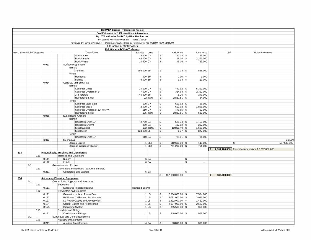
FERC Line # Sub Categories Quantity Units Unit Price Line Price Total Notes / RemarksFull Watana RCC (6 Turbines)
Description
HDR/AEA Susitna Hydroelectric ProjectCost Estimates for 1982 quantities- Alternatives
By: Leanne Andruszkiewicz, EIT Date: 1/25/09Reviewed By: David Elwood, EIT Date: 1/25/09, Modified by Hatch Acres_mb_061109, R&M 11/16/09
Alternatives- 2008 Dollars
By: DTA with edits for RCC by R&M/Hatch Acres
Overburden 3,200 CY 17.14$ 55,000$ Rock Usable 46,000 CY 49.16$ 2,261,000$ Rock Waste 14,500 CY 49.16$ 713,000$
0.913 Surface PreparationTunnels
Tunnels 266,000 SF 3.33$ 886,000$ Portals
Horizontal 600 SF 2.30$ 1,000$ Inclined 6,000 SF 3.33$ 20,000$
0.914 Concrete and ShotcreteTunnels
Concrete Lining 14,500 CY 440.92$ 6,393,000$ Concrete Overbreak 6" 7,500 CY 314.94$ 2,362,000$ 2" Shotcrete 45,600 SF 5.26$ 240,000$ Reinforcing Steel 22 TON 2,887.51$ 64,000$
Portals Concrete Base Slab 100 CY 651.93$ 65,000$ Concrete Walls 2,900 CY 651.93$ 1,891,000$ Concrete Overbreak 12" H/6" V 110 CY 471.65$ 52,000$ Reinforcing Steel 195 TON 2,887.51$ 563,000$
0.915 Support and Anchors Tunnels
Rockbolts 1" @ 12' 2,750 EA 528.34$ 1,453,000$ Rockbolts 1" @ 9' 480 EA 432.12$ 207,000$ Steel Support 132 TONS 12,801.49$ 1,690,000$ Steel Mesh 133,000 SF 6.37$ 847,000$
PortalsRockbolts 1" @ 15' 110 EA 735.81$ 81,000$
0.91c Mechanical ck sum0.91c Mechanical ck sumStoplog Guides 1 SET 112,600.00$ 113,000$ 557,539,000$ Stoplogs Includes Follower 1 SET 751,200.00$ 751,000$
2,864,400,000$ for embankment dam $ 3,202,800,000333 Waterwheels, Turbines and Generators
0.11 Turbines and Governors0.111 Supply 6 EA -$ 0.112 Install 6 EA -$
0.2 Generators and Exciters 0.21 Generators and Exciters (Supply and Install)
0.211 Generators and Exciters 6 EA -$ 487,000,000.00$ 487,000,000$
334 Accessory Electrical Equipment0.1 Connections, Supports and Structures
0.11 Structures0.111 Structures (included Below) (Included Below)
0.12 Conductors and Insulators0.121 Generator Isolated Phase Bus 1 LS 7,584,000.00$ 7,584,000$ 0.122 HV Power Cables and Accessories 1 LS 3,081,000.00$ 3,081,000$ 0.123 LV Power Cables and Accessories 1 LS 1,422,000.00$ 1,422,000$ 0.124 Control Cables and Accessories 1 LS 2,607,000.00$ 2,607,000$ 0.125 Grounding System 1 LS 355,500.00$ 356,000$
0.13 Conduits and Fittings0.131 Conduits and Fittings 1 LS 948,000.00$ 948,000$
0.2 Switchgear and Control Equipment0.21 Auxiliary Transformers
0.211 Auxiliary Transformers 4 EA 83,811.00$ 335,000$
By: DTA edited for RCC by R&M/HAC Page 10 of 16 Alternative: Full Watana RCC
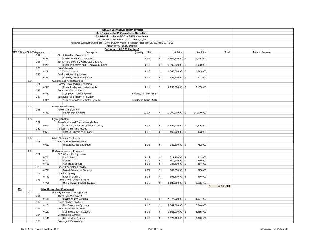
FERC Line # Sub Categories Quantity Units Unit Price Line Price Total Notes / RemarksFull Watana RCC (6 Turbines)
Description
HDR/AEA Susitna Hydroelectric ProjectCost Estimates for 1982 quantities- Alternatives
By: Leanne Andruszkiewicz, EIT Date: 1/25/09Reviewed By: David Elwood, EIT Date: 1/25/09, Modified by Hatch Acres_mb_061109, R&M 11/16/09
Alternatives- 2008 Dollars
By: DTA with edits for RCC by R&M/Hatch Acres
0.22 Circuit Breakers Generators0.221 Circuit Breakers Generators 6 EA 1,504,300.00$ 9,026,000$
0.23 Surge Protectors and Generator Cubicles0.231 Surge Protectors and Generator Cubicles 1 LS 1,090,200.00$ 1,090,000$
0.24 Switch boards0.241 Switch boards 1 LS 1,848,600.00$ 1,849,000$
0.25 Auxiliary Power Equipment0.251 Auxiliary Power Equipment 1 LS 521,400.00$ 521,000$
0.3 Cubicles and Appurtenances0.31 Control, relay and meter boards
0.311 Control, relay and meter boards 1 LS 2,133,000.00$ 2,133,000$ 0.32 Computer Control System
0.321 Computer Control System (Included in Trans-Ems)0.33 Supervisor and Telemeter System
0.331 Supervisor and Telemeter System Included in Trans EMS)
0.4 Power Transformers 0.41 Power Transformers
0.411 Power Transformers 10 EA 2,000,000.00$ 20,000,000$
0.5 Lighting System0.51 Powerhouse and Transformer Gallery
0.511 Powerhouse and Transformer Gallery 1 LS 1,824,900.00$ 1,825,000$ 0.52 Access Tunnels and Roads
0.521 Access Tunnels and Roads 1 LS 402,900.00$ 403,000$
0.6 Misc. Electrical Equipment0.61 Misc. Electrical Equipment
0.611 Misc. Electrical Equipment 1 LS 782,100.00$ 782,000$
0.7 Surface Accessory Equipment0.71 34.5 kV and LV Equipment
0.711 Switchboard 1 LS 213,300.00$ 213,000$ 0.712 Cables 1 LS 450,300.00$ 450,000$ 0.713 Aux Transformers 1 LS 284,400.00$ 284,000$
0.73 Diesel Generator- Standby 0.731 Diesel Generator- Standby 2 EA 347,550.00$ 695,000$
0.74 Exterior Lighting 0.741 Exterior Lighting 1 LS 355,500.00$ 356,000$
0.75 Mimic Board- Control Building0.751 Mimic Board- Control Building 1 LS 1,185,000.00$ 1,185,000$
57,100,000$ 335 Misc Powerplant Equipment
0.1 Auxiliary Systems- Underground0.11 Station Water Systems
0.111 Station Water Systems 1 LS 4,977,000.00$ 4,977,000$ 0.12 Fire Protection Systems
0.121 Fire Protection Systems 1 LS 2,844,000.00$ 2,844,000$ 0.13 Compressed Air Systems
0.131 Compressed Air Systems 1 LS 3,555,000.00$ 3,555,000$ 0.14 Oil Handling Systems
0.141 Oil Handling Systems 1 LS 2,370,000.00$ 2,370,000$ 0.15 Drainage & Dewatering
By: DTA edited for RCC by R&M/HAC Page 11 of 16 Alternative: Full Watana RCC

FERC Line # Sub Categories Quantity Units Unit Price Line Price Total Notes / RemarksFull Watana RCC (6 Turbines)
Description
HDR/AEA Susitna Hydroelectric ProjectCost Estimates for 1982 quantities- Alternatives
By: Leanne Andruszkiewicz, EIT Date: 1/25/09Reviewed By: David Elwood, EIT Date: 1/25/09, Modified by Hatch Acres_mb_061109, R&M 11/16/09
Alternatives- 2008 Dollars
By: DTA with edits for RCC by R&M/Hatch Acres
0.151 Drainage & Dewatering 1 LS 5,214,000.00$ 5,214,000$ 0.16 Heating, Ventilation and Cooling System
0.161 Heating, Ventilation and Cooling System 1 LS 3,555,000.00$ 3,555,000$ 0.17 Miscellaneous
0.171 Miscellaneous 1 LS 2,370,000.00$ 2,370,000$ 0.2 Auxiliary Systems- Surface Facilities
0.21 Auxiliary Systems- Surface Facilities0.211 Auxiliary Systems- Surface Facilities 1 LS 711,000.00$ 711,000$
0.3 Auxiliary Equipment0.31 Powerhouse Cranes
0.311 Powerhouse Cranes 2 EA 1,783,800.00$ 3,568,000$ 0.32 Elevators
0.321 Elevators 1 LS 545,100.00$ 545,000$ 0.33 Miscellaneous Cranes and Hoists
0.331 Miscellaneous Cranes and Hoists 1 LS 505,500.00$ 506,000$ 0.34 Machine Shop Equipment
0.341 Machine Shop Equipment 1 LS 2,022,000.00$ 2,022,000$ 0.4 General Station Equipment (Included in Mechanical And Electrical Systems)0.5 Communications Equipment 1 LS 213,300.00$ 213,000$
32,450,000$ 336 Roads, Rails and Air Facilities
0.1 Roads 0.11 Pioneer Roads and Bridges
0.111 Gold Creek- Watana Road (58 mi)
Clearing 546 ACRE 11,416.62$ 6,235,000$ Waste Excavation 1,570,824 CY 9.51$ 14,939,000$ Common Excavation 1,407,288 CY 8.32$ 11,709,000$ 18" Culverts 16,723 LF 62.55$ 1,046,000$ 36" Culverts 5 LS 32,760.98$ 158,000$ D-1 Base Material 321,146 TON 45.47$ 14,603,000$ Fabric 15,428 SY 6.73$ 104,000$
Maintenance 121 MI/YR 9,008.99$ 1,089,000$ 0.112 Gold Creek- Parks
Road (41.25 Miles )Clearing 98 ACRE 11,416.62$ 1,123,000$ Waste Excavation 228,086 CY 9.51$ 2,169,000$ Common Excavation 165,200 CY 8.32$ 1,374,000$ 18" Culverts 2,453 LF 62.55$ 153,000$ 36" Culverts 0 LS 35,451.31$ 9,000$ D-1 Base Material 59,371 TON 45.47$ 2,700,000$ Fabric 3,986 SY 6.73$ 27,000$
Maintenance 22 MI/YR 9,008.32$ 199,000$ 0.113 Devil Canyon Low Level Crossing
Crossing (7.88 Miles) Clearing 170 ACRE 11,416.62$ Waste Excavation 498,845 CY 9.51$ Common Excavation 549,417 CY 8.32$ Rock Excavation 749,641 CY 28.45$ 18" Culverts 5,100 LF 62.55$ Bridge 1 LS 120,000,000.00$ D-1 Base Material 36,966 TON 45.47$
Maintenance 118 MI/YR 11,258.74$
By: DTA edited for RCC by R&M/HAC Page 12 of 16 Alternative: Full Watana RCC

FERC Line # Sub Categories Quantity Units Unit Price Line Price Total Notes / RemarksFull Watana RCC (6 Turbines)
Description
HDR/AEA Susitna Hydroelectric ProjectCost Estimates for 1982 quantities- Alternatives
By: Leanne Andruszkiewicz, EIT Date: 1/25/09Reviewed By: David Elwood, EIT Date: 1/25/09, Modified by Hatch Acres_mb_061109, R&M 11/16/09
Alternatives- 2008 Dollars
By: DTA with edits for RCC by R&M/Hatch Acres
0.114 Gold Creek- Watana (41.25 miles) 1 LS 28,132,000$
0.12 Permanent Roads and Bridges0.124 Parks Highway to Watana (62 mi) 62 MI 3,000,000.00$ 3,000,000$ 0.125 Susitna Bridge 40800 SF 450.00$ 18,360,000$
0.2 Rail Facilities0.24 Permanent Railroad (including railheads)
0.244 Gold Creek to Watana- RailR-1, (33 Mi)
Clearing 671 AC 11,416.62$ 7,662,183$ Waste Excavation 1687883 CY 9.51$ 16,051,766$ Common Excavation 3307678 CY 8.32$ 27,519,880$ Rock Excavation 9114 CY 28.51$ 259,867$ Borrow 449500 CY 11.88$ 5,340,060$ Subballast 711055 CY 18.15$ 12,902,807$ Grade "A" Base Material 6650 CY 35.45$ 235,729$ D-1 Base material 2400 TON 43.20$ 103,680$ A.C. Surfacing 2200 TON 198.00$ 435,600$ Dock Lumber 16 MBF 1,258.60$ 20,138$ 18" Culvert 20093 LF 68.26$ 1,371,458$ 36" + Culverts 0 LS 92,160.00$ -$ Fabric 12930 SY 9.00$ 116,369$ Thaw Pipes 41843 LF 95.04$ 3,976,745$ Topsoil & Seed 431 AC 10,800.00$ 4,653,257$ Rail Yard Control Devices 1 LS 1,800.00$ 1,800$ Bridges 0 SF 900.00$ -$ Trackage 325940 LF 350.00$ 114,079,000$
MaintenanceRail 406 Mile-years 10,000.00$ 4,060,000$ Railhead 7 years 75,000.00$ 525,000$
0.13 Site Roads0.131 Construction Roads
Site Roads 20 Mile 12,554,637.23$ 251,093,000$ Maintenance 141 MI/YRS 223,092.85$ 31,456,000$
0.132 Permanent RoadsPermanent Roads 6 MILE 1,287,997.42$ 7,728,000$
By: DTA edited for RCC by R&M/HAC Page 13 of 16 Alternative: Full Watana RCC
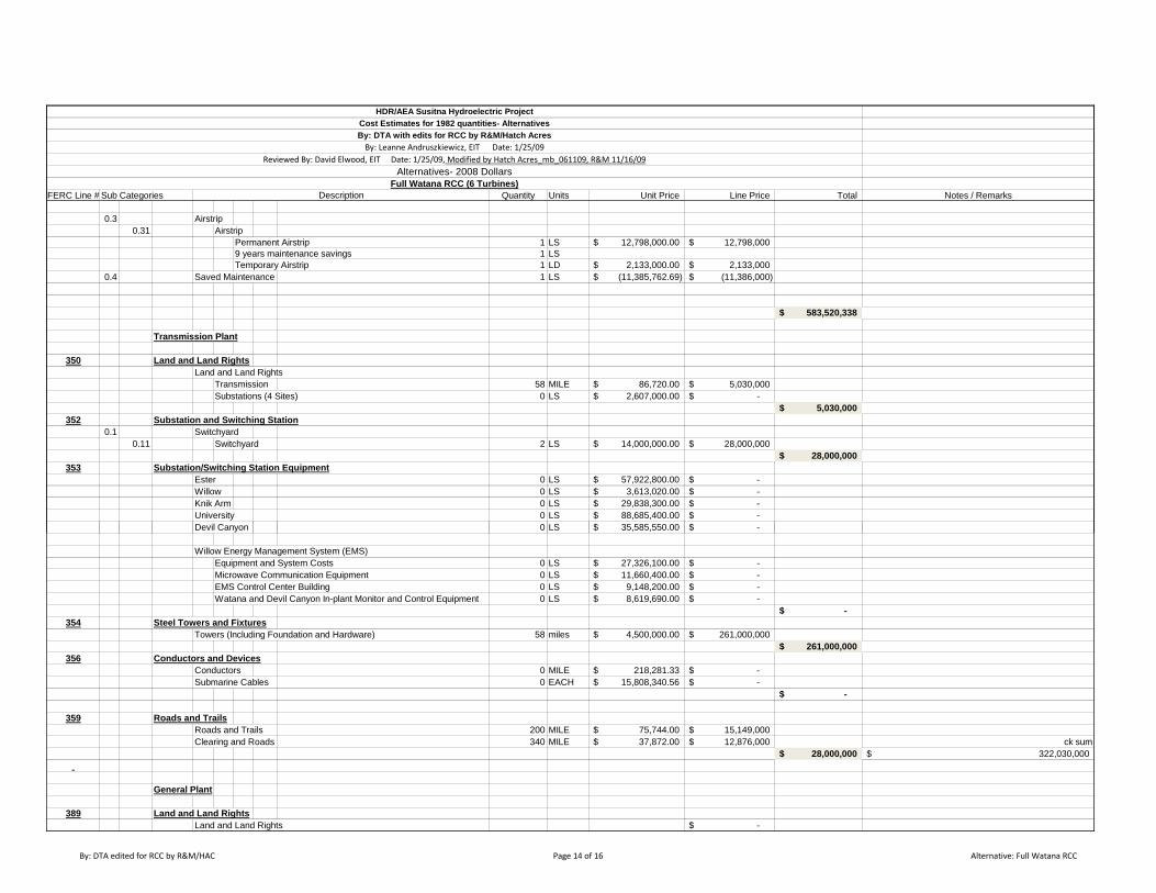
FERC Line # Sub Categories Quantity Units Unit Price Line Price Total Notes / RemarksFull Watana RCC (6 Turbines)
Description
HDR/AEA Susitna Hydroelectric ProjectCost Estimates for 1982 quantities- Alternatives
By: Leanne Andruszkiewicz, EIT Date: 1/25/09Reviewed By: David Elwood, EIT Date: 1/25/09, Modified by Hatch Acres_mb_061109, R&M 11/16/09
Alternatives- 2008 Dollars
By: DTA with edits for RCC by R&M/Hatch Acres
0.3 Airstrip0.31 Airstrip
Permanent Airstrip 1 LS 12,798,000.00$ 12,798,000$ 9 years maintenance savings 1 LSTemporary Airstrip 1 LD 2,133,000.00$ 2,133,000$
0.4 Saved Maintenance 1 LS (11,385,762.69)$ (11,386,000)$
583,520,338$
Transmission Plant
350 Land and Land Rights Land and Land Rights
Transmission 58 MILE 86,720.00$ 5,030,000$ Substations (4 Sites) 0 LS 2,607,000.00$ -$
5,030,000$ 352 Substation and Switching Station
0.1 Switchyard0.11 Switchyard 2 LS 14,000,000.00$ 28,000,000$
28,000,000$ 353 Substation/Switching Station Equipment
Ester 0 LS 57,922,800.00$ -$ Willow 0 LS 3,613,020.00$ -$ Knik Arm 0 LS 29,838,300.00$ -$ University 0 LS 88,685,400.00$ -$
$ $Devil Canyon 0 LS 35,585,550.00$ -$
Willow Energy Management System (EMS) Equipment and System Costs 0 LS 27,326,100.00$ -$ Microwave Communication Equipment 0 LS 11,660,400.00$ -$ EMS Control Center Building 0 LS 9,148,200.00$ -$ Watana and Devil Canyon In-plant Monitor and Control Equipment 0 LS 8,619,690.00$ -$
-$ 354 Steel Towers and Fixtures
Towers (Including Foundation and Hardware) 58 miles 4,500,000.00$ 261,000,000$ 261,000,000$
356 Conductors and DevicesConductors 0 MILE 218,281.33$ -$ Submarine Cables 0 EACH 15,808,340.56$ -$
-$
359 Roads and TrailsRoads and Trails 200 MILE 75,744.00$ 15,149,000$ Clearing and Roads 340 MILE 37,872.00$ 12,876,000$ ck sum
28,000,000$ 322,030,000$
General Plant
389 Land and Land RightsLand and Land Rights -$
By: DTA edited for RCC by R&M/HAC Page 14 of 16 Alternative: Full Watana RCC

FERC Line # Sub Categories Quantity Units Unit Price Line Price Total Notes / RemarksFull Watana RCC (6 Turbines)
Description
HDR/AEA Susitna Hydroelectric ProjectCost Estimates for 1982 quantities- Alternatives
By: Leanne Andruszkiewicz, EIT Date: 1/25/09Reviewed By: David Elwood, EIT Date: 1/25/09, Modified by Hatch Acres_mb_061109, R&M 11/16/09
Alternatives- 2008 Dollars
By: DTA with edits for RCC by R&M/Hatch Acres
390 Structures and ImprovementsStructures and Improvements -$
391 Office Furniture and EquipmentOffice Furniture and Equipment -$
392 Transportation EquipmentTransportation Equipment -$
393 Stores EquipmentStores Equipment -$
394 Tools Shop and Garage EquipmentTools Shop and Garage Equipment -$
395 Laboratory EquipmentLaboratory Equipment -$
396 Power-Operated EquipmentPower-Operated Equipment -$
397 Communications EquipmentCommunications Equipment -$
398 Miscellaneous EquipmentMiscellaneous Equipment -$
399 Other Tangible PropertyOther Tangible Property 1 LS 11,850,000.00$ 11,850,000$ Saved Maintence 1 LS (231,219.51)$ (231,000)$
11,600,000$ Indirect Costs
61 Temporary Construction FacilitiesTemporary Construction Facilities
62 Construction EquipmentConstruction Equipment
63 Main Construction Camp 0.1 Main Construction Camp 1 LS 624,355,816$
Saved Maintence 1 LS (12,182,552.51)$
Site Preparation 6455000Buildings 29643000utilities 24025000
60123000 5 300,615,000.00$
MAIN CONSTRUCTION VILLAGEsite prep 6987000buildings 19753000utilities 9699000
By: DTA edited for RCC by R&M/HAC Page 15 of 16 Alternative: Full Watana RCC

FERC Line # Sub Categories Quantity Units Unit Price Line Price Total Notes / RemarksFull Watana RCC (6 Turbines)
Description
HDR/AEA Susitna Hydroelectric ProjectCost Estimates for 1982 quantities- Alternatives
By: Leanne Andruszkiewicz, EIT Date: 1/25/09Reviewed By: David Elwood, EIT Date: 1/25/09, Modified by Hatch Acres_mb_061109, R&M 11/16/09
Alternatives- 2008 Dollars
By: DTA with edits for RCC by R&M/Hatch Acres
36439000 5 182,195,000.00$ 300,615,000$ 244,249,688$ Camp cost to reflect lower volume ( 0.8125)
64 Labor ExpenseLabor Expense (Included In Direct Costs)
65 SuperintendenceSuperintendence (Included In Direct Costs)
66 InsuranceInsurance (Included In Direct Costs)
68 Mitigation Fishery, Terrestrial and RecrationalMitigation (Not included in 1982 study) -$
69 FeesFees
Subtotal 4,882,000,000$ Contingency 21.313 % 1,040,500,000$
Subtotal71A Engineering (4%), Enviornmental (2%), Regulatory(1%) and Construction Mana 7 % 341,700,000$ 71B Construction Management (4%) 4 % 195,300,000$ 72 Legal Expenses 0 %75 Taxes 0 %76 Administrative & Gen. Expenses 0 %77 Interest 0 %80 Earnings/Expenses During Construction 0 %
Total Project Cost 6,459,500,000$
By: DTA edited for RCC by R&M/HAC Page 16 of 16 Alternative: Full Watana RCC

R&M Consultants - Hatch Acres AEA – Susitna RCC Dam Cost Evaluation
11/17/2009 FINAL
Appendix D –
Cost Estimate Detail – High Devil Canyon RCC
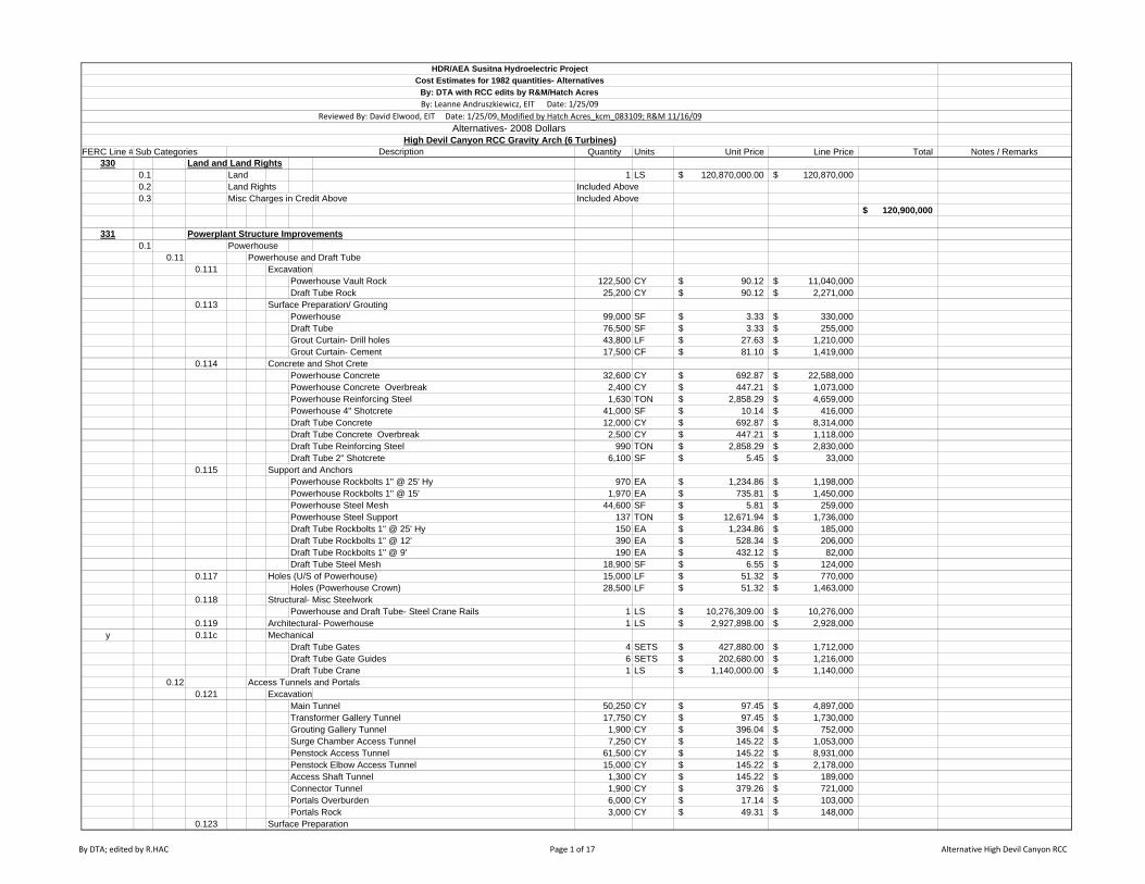
FERC Line # Sub Categories Quantity Units Unit Price Line Price Total Notes / Remarks330 Land and Land Rights
0.1 Land 1 LS 120,870,000.00$ 120,870,000$ 0.2 Land Rights Included Above0.3 Misc Charges in Credit Above Included Above
120,900,000$
331 Powerplant Structure Improvements0.1 Powerhouse
0.11 Powerhouse and Draft Tube0.111 Excavation
Powerhouse Vault Rock 122,500 CY 90.12$ 11,040,000$ Draft Tube Rock 25,200 CY 90.12$ 2,271,000$
0.113 Surface Preparation/ GroutingPowerhouse 99,000 SF 3.33$ 330,000$ Draft Tube 76,500 SF 3.33$ 255,000$ Grout Curtain- Drill holes 43,800 LF 27.63$ 1,210,000$ Grout Curtain- Cement 17,500 CF 81.10$ 1,419,000$
0.114 Concrete and Shot CretePowerhouse Concrete 32,600 CY 692.87$ 22,588,000$ Powerhouse Concrete Overbreak 2,400 CY 447.21$ 1,073,000$ Powerhouse Reinforcing Steel 1,630 TON 2,858.29$ 4,659,000$ Powerhouse 4" Shotcrete 41,000 SF 10.14$ 416,000$ Draft Tube Concrete 12,000 CY 692.87$ 8,314,000$ Draft Tube Concrete Overbreak 2,500 CY 447.21$ 1,118,000$ Draft Tube Reinforcing Steel 990 TON 2,858.29$ 2,830,000$ Draft Tube 2" Shotcrete 6,100 SF 5.45$ 33,000$
0.115 Support and AnchorsPowerhouse Rockbolts 1" @ 25' Hy 970 EA 1,234.86$ 1,198,000$ Powerhouse Rockbolts 1" @ 15' 1,970 EA 735.81$ 1,450,000$ Powerhouse Steel Mesh 44,600 SF 5.81$ 259,000$ Powerhouse Steel Support 137 TON 12,671.94$ 1,736,000$ Draft Tube Rockbolts 1" @ 25' Hy 150 EA 1,234.86$ 185,000$ Draft Tube Rockbolts 1" @ 12' 390 EA 528.34$ 206,000$ Draft Tube Rockbolts 1" @ 9' 190 EA 432.12$ 82,000$ Draft Tube Steel Mesh 18,900 SF 6.55$ 124,000$
0.117 Holes (U/S of Powerhouse) 15,000 LF 51.32$ 770,000$ Holes (Powerhouse Crown) 28,500 LF 51.32$ 1,463,000$
0.118 Structural- Misc SteelworkPowerhouse and Draft Tube- Steel Crane Rails 1 LS 10,276,309.00$ 10,276,000$
0.119 Architectural- Powerhouse 1 LS 2,927,898.00$ 2,928,000$ y 0.11c Mechanical
Draft Tube Gates 4 SETS 427,880.00$ 1,712,000$ Draft Tube Gate Guides 6 SETS 202,680.00$ 1,216,000$ Draft Tube Crane 1 LS 1,140,000.00$ 1,140,000$
0.12 Access Tunnels and Portals 0.121 Excavation
Main Tunnel 50,250 CY 97.45$ 4,897,000$ Transformer Gallery Tunnel 17,750 CY 97.45$ 1,730,000$ Grouting Gallery Tunnel 1,900 CY 396.04$ 752,000$ Surge Chamber Access Tunnel 7,250 CY 145.22$ 1,053,000$ Penstock Access Tunnel 61,500 CY 145.22$ 8,931,000$ Penstock Elbow Access Tunnel 15,000 CY 145.22$ 2,178,000$ Access Shaft Tunnel 1,300 CY 145.22$ 189,000$ Connector Tunnel 1,900 CY 379.26$ 721,000$ Portals Overburden 6,000 CY 17.14$ 103,000$ Portals Rock 3,000 CY 49.31$ 148,000$
0.123 Surface Preparation
High Devil Canyon RCC Gravity Arch (6 Turbines)Description
HDR/AEA Susitna Hydroelectric ProjectCost Estimates for 1982 quantities- Alternatives
By: DTA with RCC edits by R&M/Hatch AcresBy: Leanne Andruszkiewicz, EIT Date: 1/25/09
Reviewed By: David Elwood, EIT Date: 1/25/09, Modified by Hatch Acres_kcm_083109; R&M 11/16/09Alternatives- 2008 Dollars
By DTA; edited by R.HAC Page 1 of 17 Alternative High Devil Canyon RCC

FERC Line # Sub Categories Quantity Units Unit Price Line Price Total Notes / RemarksHigh Devil Canyon RCC Gravity Arch (6 Turbines)
Description
HDR/AEA Susitna Hydroelectric ProjectCost Estimates for 1982 quantities- Alternatives
By: DTA with RCC edits by R&M/Hatch AcresBy: Leanne Andruszkiewicz, EIT Date: 1/25/09
Reviewed By: David Elwood, EIT Date: 1/25/09, Modified by Hatch Acres_kcm_083109; R&M 11/16/09Alternatives- 2008 Dollars
Main Tunnel Slab 53,100 SF 2.21$ 117,000$ Penstock Access Slab 65,200 SF 2.21$ 144,000$ Horizontal Portal 200 SF 2.30$ -$ Inclined Portal 2,100 SF 3.33$ 7,000$
0.124 Concrete and Shot CreteMain Portal
Concrete Slab 30 CY 406.27$ 12,000$ Concrete Walls 570 CY 406.27$ 232,000$ Concrete Overbreak 50 CY 368.48$ 18,000$ Reinforcing Steel 40 TON 2,887.51$ 116,000$
TunnelsConcrete Slab Main Tunnel 1,950 CY 503.90$ 983,000$ Concrete Plugs Penstock Elbow ACC 15,000 CY 755.86$ 11,338,000$ Concrete Overbreak Main Tunnel 6" 1,000 CY 346.43$ 346,000$ Reinforcing Steel 70 TON 2,887.51$ 202,000$ 2 " Shotcrete Main Tunnel 20,100 SF 5.26$ 106,000$ 2 " Shotcrete Transformer Gal 7,100 SF 5.26$ 37,000$ 2 " Shotcrete Surge Chamber Acc 3,900 SF 5.26$ 21,000$ 2 " Shotcrete Penstock Access 24,700 SF 5.26$ 130,000$ 2 " Shotcrete Penstock Elbow Acc 7,100 SF 5.26$ 37,000$ 2 " Shotcrete Access Shaft 300 SF 5.26$ 2,000$ 2 " Shotcrete Grout Gallery 800 SF 5.26$ 4,000$ 2 " Shotcrete Connector Tunnel 800 SF 5.26$ 4,000$
0.125 Support and AnchorsMain Tunnel
Rockbolts 1" @12' 1,200 EA 528.34$ 634,000$ Rockbolts 1" @ 9' 250 EA 432.12$ 108,000$ Steel Mesh 63,000 SF 6.37$ 401,000$ Steel Support 66 TON 12,801.49$ 845,000$
Main Tunnel PortalRockbolts 1" @15' 50 EA 735.79$ 37,000$
Transformer Gallery Tunnel Rockbolts 1" @12' 410 EA 528.34$ 217,000$ Rockbolts 1" @ 9' 70 EA 432.12$ 30,000$ Steel Mesh 22,500 SF 5.89$ 133,000$ Steel Support 24 TON 12,801.49$ 307,000$
Grouting Gallery TunnelRockbolts 3/4" @ 6' 160 EA 327.15$ 52,000$ Steel Mesh 160 SF 6.37$ 1,000$ Steel Support 2 TON 12,801.49$ 26,000$
Surge Chamber Access TunnelRockbolts 1" @12' 230 EA 528.34$ 122,000$ Rockbolts 1" @ 9' 50 EA 432.12$ 22,000$ Steel Mesh 12,050 SF 6.37$ 77,000$ Steel Support 14 TON 12,801.49$ 179,000$
Penstock Access TunnelRockbolts 1" @12' 1,430 EA 528.34$ 756,000$ Rockbolts 1" @ 9' 240 EA 432.12$ 104,000$ Steel Mesh 77,500 SF 6.37$ 494,000$ Steel Support 58 TON 12,801.49$ 742,000$
Penstock Elbow Access TunnelRockbolts 1" @12' 420 EA 528.34$ 222,000$ Rockbolts 1" @ 9' 120 EA 432.12$ 52,000$ Steel Mesh 22,500 SF 6.37$ 143,000$ Steel Support 30 TON 12,801.49$ 384,000$
Access Shaft Tunnel
By DTA; edited by R.HAC Page 2 of 17 Alternative High Devil Canyon RCC
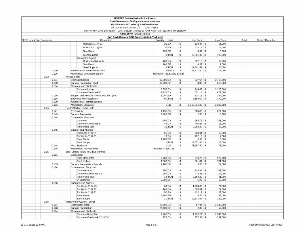
FERC Line # Sub Categories Quantity Units Unit Price Line Price Total Notes / RemarksHigh Devil Canyon RCC Gravity Arch (6 Turbines)
Description
HDR/AEA Susitna Hydroelectric ProjectCost Estimates for 1982 quantities- Alternatives
By: DTA with RCC edits by R&M/Hatch AcresBy: Leanne Andruszkiewicz, EIT Date: 1/25/09
Reviewed By: David Elwood, EIT Date: 1/25/09, Modified by Hatch Acres_kcm_083109; R&M 11/16/09Alternatives- 2008 Dollars
Rockbolts 1" @12' 20 EA 528.34$ 11,000$ Rockbolts 1" @ 9' 20 EA 432.12$ 9,000$ Steel Mesh 930 SF 6.37$ 6,000$ Steel Support 8 TON 12,801.49$ 102,000$
Connector TunnelRockbolts 3/4" @ 6' 160 EA 327.15$ 52,000$ Steel Mesh 160 SF 6.37$ 1,000$ Steel Support 2 TON 12,801.49$ 26,000$
0.129 Architectural- Main Portal Doors 2 SETS 158,371.90$ 317,000$ 0.12c Mechanical Ventilation System Included in (63.81 and 63.82)
0.13 Access Shaft0.131 Excavation Rock 13,700 CY 227.67$ 3,119,000$ 0.133 Surface Preparation Shaft 64,000 SF 3.33$ 213,000$ 0.134 Concrete and Shot Crete
Concrete Lining 3,350 CY 944.82$ 3,165,000$ Concrete Overbreak 6" 1,220 CY 551.14$ 672,000$
0.135 Support and Anchors - Rockbolts 3/4" @ 6' 1,050 EA 327.15$ 344,000$ 0.138 Structural Misc Steelwork 50 TON 7,395.00$ 370,000$ 0.139 Architectural- control Building 0.13c Mechanical Elevators 1 LS 2,368,815.00$ 2,369,000$
0.14 Fire Protection Head Tank0.141 Excavation 1,150 CY 588.80$ 677,000$ 0.143 Surface Preparation 2,800 SF 2.30$ 6,000$ 0.144 Concrete & Shotcrete
Concrete 250 CY 963.72$ 241,000$ Concrete Overbreak 6" 45 CY 406.27$ 18,000$ Reinforcing Steel 10 TON 2,858.29$ 29,000$
0.145 Support and AnchorsRockbolts 1" @12' 25 EA 528.34$ 13,000$ Rockbolts 1" @ 9' 10 EA 432.12$ 4,000$ Steel Mesh 1,200 SF 6.30$ 8,000$ Steel Support 2 TON 12,671.95$ 25,000$
0.148 Misc Steelwork 1 LS 73,297.50$ 73,000$ 0.14c Mechanical Piping/Valves (Included in 335.12)
0.15 Bus Tunnels (totals for 3 Bus Tunnels)0.151 Excavation
Rock Horizontal 2,700 CY 213.70$ 577,000$ Rock Inclined 1,300 CY 601.04$ 781,000$
0.153 Surface Preparation- Tunnels 7,100 SF 3.33$ 24,000$ 0.154 Concrete and Shotcrete
Concrete Slab 350 CY 818.84$ 287,000$ Concrete Overbreak 12" 250 CY 472.41$ 118,000$ Reinforcing Steel 18 TON 2,858.29$ 51,000$ 2" Shotcrete 2,200 SF 5.26$ 12,000$
0.155 Supports and AnchorsRockbolts 1" @ 25' 60 EA 1,234.86$ 74,000$ Rockbolts 1" @ 12' 140 EA 528.34$ 74,000$ Rockbolts 1" @ 9' 50 EA 432.12$ 22,000$ Steel Mesh 6,800 SF 6.30$ 43,000$ Steel Support 11 TON 12,671.94$ 139,000$
0.16 Transformer Gallery Tunnel0.161 Excavation- Rock 26,800 CY 87.44$ 2,343,000$ 0.163 Surface Preparation 24,600 SF 2.30$ 57,000$ 0.164 Concrete and Shotcrete
Concrete Base Slab 2,400 CY 1,228.27$ 2,948,000$ Concrete Overbreak 12"H/6"V 770 CY 377.93$ 291,000$
By DTA; edited by R.HAC Page 3 of 17 Alternative High Devil Canyon RCC

FERC Line # Sub Categories Quantity Units Unit Price Line Price Total Notes / RemarksHigh Devil Canyon RCC Gravity Arch (6 Turbines)
Description
HDR/AEA Susitna Hydroelectric ProjectCost Estimates for 1982 quantities- Alternatives
By: DTA with RCC edits by R&M/Hatch AcresBy: Leanne Andruszkiewicz, EIT Date: 1/25/09
Reviewed By: David Elwood, EIT Date: 1/25/09, Modified by Hatch Acres_kcm_083109; R&M 11/16/09Alternatives- 2008 Dollars
Reinforcing Steel 120 TON 2,858.29$ 343,000$ 0.165 Support and Anchors
Rockbolts 1" @ 25' 600 EA 1,234.86$ 741,000$ Rockbolts 1" @ 15' 270 EA 735.81$ 199,000$ Steel Mesh 20,700 SF 5.81$ 120,000$ Steel Support 29 TON 12,671.94$ 367,000$
0.167 Drainage Holes 8,300 LF 47.95$ 398,000$ 0.17 Cable Shafts
0.171 Excavation Rock 3,400 CY 601.04$ 2,044,000$ 0.173 Surface Preparation Shafts 41,400 SF 3.33$ 138,000$ 0.174 Concrete and Shotcrete
Concrete Lining 1,040 CY 1,763.66$ 1,834,000$ Concrete Overbreak 6" 800 CY 881.83$ 705,000$
0.175 Supports and Anchors- Rockbolts 3/4" @ 6' 650 EA 327.15$ 213,000$ 0.178 Structural Misc Steelwork 18 TON 15,602.00$ 281,000$ 0.179 Architectural- Enclosures 1 LS 199,317.00$ 199,000$ 0.17c Mechanical Hoist 2 EA 476,960.00$ 954,000$
0.18 Dewatering (during Construction)0.181 Dewatering (Power Facilities) 1 LS 1,336,798.50$ 1,337,000$
0.19 Instrumentation0.191 Instrumentation 1 LS 1,714,813.50$ 1,715,000$
0.2 Misc Buildings (Control Buildings) 1 LS 4,433,085.00$ 4,433,000$ 0.3 Permanent Town (included in 63.5)
158,700,000$ 332 Reservoir, Dams and Waterways
0.1 Reservoir0.11 Reservoir Clearing 37,500 ACRE 3,005.85$ 112,719,000$ (same as embankment dam)
0.2 Diversion Tunnels /Cofferdams0.21 Diversion Tunnels /Portals
0.211 ExcavationUpper Tunnel
Rock 221,000 CY 92.33$ 20,405,000$ Lower Tunnel
Rock 208,000 CY 92.33$ 19,205,000$ Excavate Concrete for Plug 700 CY 96.92$ 68,000$
Upstream Upper PortalRock Usable (Face Only) 11,200 CY 49.16$ 551,000$
Upstream Lower Portal (Including Most Exc for Upper Portal)Rock Usable 108,000 CY 49.16$ 5,309,000$ Rock Waste 21,750 CY 49.16$ 1,069,000$
Downstream PortalsOverburden 17,000 CY 17.14$ 291,000$ Rock Usable 120,000 CY 49.16$ 5,899,000$ Rock Waste 28,000 CY 49.16$ 1,376,000$
Emergency Release ChambersExcavate Concrete for Plugs 1,800 CY 101.98$ 184,000$ Gate Chamber 4,700 CY 110.73$ 520,000$
Access Tunnel to Gate ChamberRock 19,100 CY 97.15$ 1,856,000$
0.212 Fill- Temp for Coffer Dam to Construct Upstream Portals 23,000 CY 11.66$ 268,000$ 0.213 Surface Preparation \ grouting
Upstream Upper Portal Horizontal 3,200 SF 2.30$ 7,000$ Inclined 8,600 SF 3.33$ 29,000$
Upstream Lower Portal Horizontal 1,300 SF 2.30$ 3,000$ Inclined 14,900 SF 3.33$ 50,000$
Downstream Upper PortalHorizontal 6,100 SF 2.30$ 14,000$
By DTA; edited by R.HAC Page 4 of 17 Alternative High Devil Canyon RCC

FERC Line # Sub Categories Quantity Units Unit Price Line Price Total Notes / RemarksHigh Devil Canyon RCC Gravity Arch (6 Turbines)
Description
HDR/AEA Susitna Hydroelectric ProjectCost Estimates for 1982 quantities- Alternatives
By: DTA with RCC edits by R&M/Hatch AcresBy: Leanne Andruszkiewicz, EIT Date: 1/25/09
Reviewed By: David Elwood, EIT Date: 1/25/09, Modified by Hatch Acres_kcm_083109; R&M 11/16/09Alternatives- 2008 Dollars
Inclined 20,500 SF 3.33$ 68,000$ Downstream Lower Portal
Horizontal 600 SF 2.30$ 1,000$ Inclined 5,600 SF 3.33$ 19,000$
Grout Upper Tunnel Plugs Drill Holes 4,100 LF 26.76$ 110,000$ Cement 820 CF 81.10$ 67,000$
Grout Lower Tunnel Permanent PlugsDrill Holes 2,050 LF 26.76$ 55,000$ Cement 410 CF 81.10$ 33,000$
0.214 Concrete and ShotcreteUpper Tunnel
Concrete Lining 42,400 CY 566.89$ 24,036,000$ Concrete Lining Overbreak 6" 10,200 CY 314.94$ 3,212,000$ Reinforcing Steel 24 TON 2,887.51$ 69,000$ 2" Shotcrete 56,000 SF 5.26$ 295,000$
Lower TunnelConcrete Lining 37,600 CY 566.89$ 21,315,000$ Concrete Lining for Plug 6,200 CY 428.32$ 2,656,000$ Concrete Lining Overbreak 6" 10,000 CY 314.94$ 3,149,000$ Reinforcing Steel 24 TON 2,887.51$ 69,000$ 2" Shotcrete 57,900 SF 5.26$ 305,000$
Upstream Upper PortalConcrete Headwall 3,200 CY 651.93$ 2,086,000$ Concrete Lining 1,300 CY 651.93$ 848,000$ Concrete Slab 750 CY 651.93$ 489,000$ Concrete Piers 800 CY 651.93$ 522,000$ Concrete Overbreak 12" H/6"V 300 CY 472.41$ 142,000$ Reinforcing Steel 400 TON 2,887.51$ 1,155,000$
Upstream Lower Portal Concrete Headwall 4,500 CY 651.93$ 2,934,000$ Concrete Lining 3,000 CY 651.93$ 1,956,000$ Concrete Slab 300 CY 651.93$ 196,000$ Concrete Piers 700 CY 651.93$ 456,000$ Concrete Overbreak 12" H/6"V 350 CY 472.41$ 165,000$ Reinforcing Steel 600 TON 2,887.51$ 1,733,000$
Downstream Upper PortalConcrete Headwall 500 CY 651.93$ 326,000$ Concrete Slab 100 CY 651.93$ 65,000$ Concrete Overbreak 12" H/6"V 100 CY 472.41$ 47,000$ Reinforcing Steel 40 TON 2,887.51$ 116,000$
Downstream Lower PortalConcrete Headwall 2,500 CY 651.93$ 1,630,000$ Concrete Slab 100 CY 651.93$ 65,000$ Concrete Overbreak 12" H/6"V 150 CY 472.41$ 71,000$ Reinforcing Steel 170 TON 2,887.51$ 491,000$
Downstream Flip BucketConcrete Slab 800 CY 651.93$ 522,000$ Concrete Walls 2,300 CY 651.93$ 1,499,000$ Concrete Invert 1,200 CY 651.93$ 782,000$ Concrete Overbreak 12" H/6"V 410 CY 42.41$ 17,000$ Reinforcing Steel 280 TON 2,887.51$ 809,000$
Downstream Retaining WallConcrete Slab 200 CY 651.93$ 130,000$ Concrete Walls 2,000 CY 651.93$ 1,304,000$ Concrete Overbreak 12" H/6"V 110 CY 472.41$ 52,000$ Reinforcing Steel 90 TON 2,887.51$ 260,000$
Emergency Release ChambersConcrete Plug 15,300 CY 755.86$ 11,565,000$ 4" Shotcrete 2,790 SF 10.13$ 28,000$
By DTA; edited by R.HAC Page 5 of 17 Alternative High Devil Canyon RCC

FERC Line # Sub Categories Quantity Units Unit Price Line Price Total Notes / RemarksHigh Devil Canyon RCC Gravity Arch (6 Turbines)
Description
HDR/AEA Susitna Hydroelectric ProjectCost Estimates for 1982 quantities- Alternatives
By: DTA with RCC edits by R&M/Hatch AcresBy: Leanne Andruszkiewicz, EIT Date: 1/25/09
Reviewed By: David Elwood, EIT Date: 1/25/09, Modified by Hatch Acres_kcm_083109; R&M 11/16/09Alternatives- 2008 Dollars
Access Tunnel to Gate Chamber2" Shotcrete 12,800 SF 5.26$ 67,000$
0.215 Supports and AnchorsLower Tunnel
Rockbolts 1" @ 12' 3,650 EA 528.34$ 1,928,000$ Rockbolts 1" @ 9' 620 EA 432.12$ 268,000$ Steel Mesh 217,100 SF 6.37$ 1,383,000$ Steel Support 220 TON 12,801.49$ 2,816,000$
Upper TunnelRockbolts 1" @ 12' 3,530 EA 528.34$ 1,865,000$ Rockbolts 1" @ 9' 600 EA 432.12$ 259,000$ Steel Mesh 210,200 SF 6.37$ 1,339,000$ Steel Support 213 TON 12,801.49$ 2,727,000$
Upstream Lower PortalRockbolts 1" @ 15' 240 EA 735.81$ 177,000$ Anchors 1" @ 25' 290 EA 1,234.86$ 358,000$
Upstream Upper Portal
Rockbolts 1" @ 15'(Included in Lower Portal)
Anchors 1" @ 25' 130 EA 1,234.86$ 161,000$ Downstream Lower Portal
Rockbolts 1" @ 15' 200 EA 735.81$ 147,000$ Downstream Upper Portal
Rockbolts 1" @ 15' 100 EA 735.81$ 74,000$ Retaining Wall Anchors 1" @25' 100 EA 1,234.86$ 123,000$
Emergency Release ChambersRockbolts 1" @ 25' 100 EA 1,234.86$ 123,000$ Rockbolts 1" @ 15' 125 EA 735.77$ 92,000$ Steel Mesh 3,600 SF 6.37$ 23,000$ Steel Support 14 TON 12,801.49$ 179,000$ Metal to Roof Anchors 3/4" @ 6' 20 EA 342.42$ 7,000$
Access Tunnel to Gate ChamberRockbolts 1" @ 12' 775 EA 528.34$ 409,000$ Rockbolts 1" @ 9' 240 EA 432.12$ 104,000$ Steel Mesh 39,900 SF 6.37$ 254,000$ Steel Support 55 TON 12,801.49$ 704,000$
0.218 Structural- Misc Steelwork 2,775 SF 93.61$ 260,000$ 0.21c Mechanical
Upstream Lower GatesGate Equipment 2 EA 5,073,120.00$ 10,146,000$
Upstream Upper GatesGate Equipment 2 EA 2,840,080.00$ 5,680,000$ Trashracks 1 LS 1,777,500.00$ 1,778,000$
Downstream Lower Outlet Stoplog Guides 1 LS 142,200.00$ 142,000$ Stoplogs includes follower 1 LS 1,967,100.00$ 1,967,000$
Downstream Upper Outlet Stoplog Guides 1 LS 82,950.00$ 83,000$
Low Level ReleaseSlide Gates Include Steel Liner 9 EA 3,517,470.00$ 31,657,000$
0.22 Upstream Cofferdam 0.221 Excavation
Overburden Removal 1,000 CY 11.56$ 12,000$ 0.222 Fill
Rock Fill 38,400 CY 10.90$ 419,000$ Fine Filter 16,600 CY 36.84$ 612,000$ Coarse Filter 15,900 CY 30.05$ 478,000$ Rock Shell 196,500 CY 10.50$ 2,063,000$
By DTA; edited by R.HAC Page 6 of 17 Alternative High Devil Canyon RCC

FERC Line # Sub Categories Quantity Units Unit Price Line Price Total Notes / RemarksHigh Devil Canyon RCC Gravity Arch (6 Turbines)
Description
HDR/AEA Susitna Hydroelectric ProjectCost Estimates for 1982 quantities- Alternatives
By: DTA with RCC edits by R&M/Hatch AcresBy: Leanne Andruszkiewicz, EIT Date: 1/25/09
Reviewed By: David Elwood, EIT Date: 1/25/09, Modified by Hatch Acres_kcm_083109; R&M 11/16/09Alternatives- 2008 Dollars
Closure Dike 58,500 CY 10.90$ 638,000$ Rip Rap 21,200 CY 24.26$ 514,000$
0.223 Cutoff Slurry Wallexcavation 4,850 CY 4.88$ 24,000$ slurry wall 43,600 SF 72.44$ 3,158,000$
0.22d Dewatering Initial Dewatering 1 LS 5,807,685.00$ 5,808,000$ Dewatering Maintenance 1 LS 22,377,990.00$ 22,378,000$
0.23 Down Stream Cofferdam0.231 Excavation
overburden 5,000 CY 11.56$ 58,000$ Rock 500 CY 9.91$ 5,000$ Removal of Cofferdam 14,500 CY 13.48$ 195,000$
0.232 FillRip Rap 1,800 CY 24.26$ 44,000$ Closure Dike 15,200 CY 10.90$ 166,000$
0.233 Cutoff Slurry WallExcavation 1,830 CY 4.60$ 8,000$ Slurry Wall 16,500 SF 72.44$ 1,195,000$
0.3 Main Dam0.31 Main Dam
0.311 ExcavationOverburden above el. 1470 675,333 CY 11.53$ 7,787,000$
Overburden below el. 1470 1,773,333 CY 11.06$ 19,613,000$ The ratio of foot print area of RCC dam / Embankment
Rock Usable above el. 1470 429,667 CY 43.03$ 18,489,000$ dam = 0.321Rock Usable below el. 1470 159,333 CY 43.72$ 6,966,000$ Rock Waste above el. 1470 650,000 CY 43.03$ 27,970,000$ Rock Waste below el. 1470 289,833 CY 50.18$ 14,544,000$
0.312 DamRCC 11,621,000 CY 100.00$ 1,162,100,000$ Base RCC 0 CY 110.00$ -$
0.313 Surface Prep/ GroutingSurface Preparation (same as embankment dam)
Under Core/Filters above el. 1500 1,675,000 SF 3.11$ 5,209,000$ Under Core/Filters below el. 1500 613,000 SF 3.11$ 1,906,000$
Under Shell above el. 1500 5,186,000 SF 2.15$ 11,150,000$ Under Shell below el. 1500 2,584,000 SF 2.15$ 5,556,000$
Consolidation Grout
Drill Holes 255,000 LF 11.91$ 3,037,000$ 687,000 LF from embankment dam
Cement 350,000 CF 67.81$ 23,734,000$ 687,000 CF from embankment dam
Grout Curtain
Drill Holes 465,000 LF 26.76$ 12,443,000$ 465,000 LF from embankment dam
Cement 186,000 CF 81.10$ 15,085,000$ 186,000 CF from embankment dam
Dental Concrete (same as embankment dam)Dental Concrete 85,000 CY 365.33$ 31,053,000$
0.317 DrainageHoles 136,000 LF 51.32$ 6,980,000$
0.318 BridgePrecast Bridge Beams 25,500 CY 544.85$ 13,894,000$ Unit price from item 0.614Concrete Road Deck 5,400 CY 544.85$ 2,942,000$ Unit price from item 0.614Piers 500 CY 544.85$ 272,000$ Unit price from item 0.614
0.32 Grout Galleries/Portals (3 portals , multiply by 3)0.321 Excavation
Tunnels/ Shafts- Core AreaRock Horizontal 77,400 CY 394.80$ 30,558,000$
By DTA; edited by R.HAC Page 7 of 17 Alternative High Devil Canyon RCC

FERC Line # Sub Categories Quantity Units Unit Price Line Price Total Notes / RemarksHigh Devil Canyon RCC Gravity Arch (6 Turbines)
Description
HDR/AEA Susitna Hydroelectric ProjectCost Estimates for 1982 quantities- Alternatives
By: DTA with RCC edits by R&M/Hatch AcresBy: Leanne Andruszkiewicz, EIT Date: 1/25/09
Reviewed By: David Elwood, EIT Date: 1/25/09, Modified by Hatch Acres_kcm_083109; R&M 11/16/09Alternatives- 2008 Dollars
Portals Overburden Rock 10,000 CY 17.16$ 172,000$ Rock 3,000 CY 49.16$ 147,000$
0.323 Surface PreparationPortals
Horizontal 100 SF 2.30$ -$ Inclined 500 SF 3.33$ 2,000$
0.324 Concrete and ShotcreteTunnels- Core Area
Concrete Plugs 1,000 CY 428.32$ 428,000$ Concrete Slab 2,300 CY 944.82$ 2,173,000$ Concrete Overbreak 6" 1,150 CY 755.86$ 869,000$ Reinforcing Steel 80 TON 2,887.51$ 231,000$ 2" Shotcrete 15,000 SF 5.26$ 79,000$
Tunnels-AccessConcrete Slab 1,600 CY 944.82$ 1,512,000$ Concrete Overbreak 6" 800 CY 755.86$ 605,000$ Reinforcing Steel 60 TON 2,887.51$ 173,000$ 2" Shotcrete 5,400 SF 5.26$ 28,000$
Shafts2" Shotcrete 5,000 SF 5.26$ 26,000$
Portals Concrete 60 CY 406.36$ 24,000$ Reinforcing Steel 6 TON 2,887.51$ 17,000$
0.325 Support and AnchorsTunnels- Core Area
Rockbolts 3/4" @6' 1,800 EA 327.15$ 589,000$ Steel Mesh 3,000 SF 5.37$ 16,000$ Steel Support 20 TON 12,801.49$ 256,000$
Tunnels- AccessRockbolts 3/4" @6' 1,200 EA 327.15$ 393,000$ Steel Mesh 1,100 SF 5.37$ 6,000$ Steel Support 20 TON 12,801.49$ 256,000$
Shafts Rockbolts 3/4" @6' 350 EA 327.15$ 115,000$ Steel Mesh 1,000 SF 5.37$ 5,000$
Portals Rockbolts 1" @15' 30 EA 735.81$ 22,000$
0.329 Architectural Portal DoorsPortal Doors 2 EA 42,123.66$ 84,000$
0.33 Instrumentation
0.331 Instrumentation 1 LS 10,821,538.50$ 10,822,000$ This cost is taken as 50% of embankment dam
0.4 Relict Channel (same as embankment dam)0.41 Shore Protection
0.411 Excavation Overburden Stripping 2' thick 0 CY 11.56$ -$
0.412 Fill Dump and Spread
Filter Material - 2' layer 0 CY 31.93$ -$ Rock Spalls/ Rip Rap- 3' Ave 0 CY 9.86$ -$
Shore Protection Rip Rap 0 CY 24.26$ -$ Waste Rock 0 CY 22.78$ -$
0.44 Channel Filter Blanket0.442 Fill
Coarse Filter 0 CY 33.85$ -$ Fine Filter 0 CY 43.65$ -$ Rip Rap 0 CY 24.26$ -$
By DTA; edited by R.HAC Page 8 of 17 Alternative High Devil Canyon RCC

FERC Line # Sub Categories Quantity Units Unit Price Line Price Total Notes / RemarksHigh Devil Canyon RCC Gravity Arch (6 Turbines)
Description
HDR/AEA Susitna Hydroelectric ProjectCost Estimates for 1982 quantities- Alternatives
By: DTA with RCC edits by R&M/Hatch AcresBy: Leanne Andruszkiewicz, EIT Date: 1/25/09
Reviewed By: David Elwood, EIT Date: 1/25/09, Modified by Hatch Acres_kcm_083109; R&M 11/16/09Alternatives- 2008 Dollars
0.443 Surface preparationFoundation Prep
Clearing and Grubbing 0 ACRE 3,963.11$ -$ Excavation 0 CY 15.62$ -$ $ -
0.5 Outlet Facilities 0.51 Outlet Facilities- (Intake Civil Work Include in Power Intake ) (same as embankment dam)
0.511 ExcavationInlet (Included in 332.611)Outlet (Included in 332.521)Tunnels
Rock Horizontal 83,000 CY 103.00$ 8,549,000$ Rock Inclined 9,000 CY 183.49$ 1,651,000$
0.513 Surface Preparation/ Grouting \Inlet (Included in 332.613)Outlet (Included in 332.523)Tunnels 323,500 SF 2.30$ 744,000$ Contact Grouting 1 LS 569,428.05$ 569,000$
0.514 Concrete and Shotcrete Inlet (Included in 332.614)Outlet (Included in 332.524)Tunnels
Concrete Lining 27,200 CY 944.82$ 25,699,000$ Concrete Overbreak 6" 6,200 CY 440.92$ 2,734,000$ 2" Shotcrete 12,000 SF 5.26$ 63,000$ 3" Shotcrete 19,400 SF 7.69$ 149,000$
0.515 Support and AnchorsInlet (Included in 332.615)Outlet (Included in 332.525)Tunnels
Rock Bolts 1" @6' 2,400 EA 327.15$ 785,000$ Steel Mesh 94,500 SF 6.37$ 602,000$
0.51c Mechanical Inlet
Trash Racks/Guides 1 LS 1,540,500.00$ 1,541,000$ Gate Equipment 2 EA 3,317,040.00$ 6,634,000$ Stoplog Guides 2 SETS 213,940.00$ 428,000$
OutletFixed Cone Valves 6 +1 Spare 1 LS 4,500,630.00$ 4,501,000$ Ring Follower Gates 6 EA 1,936,494.80$ 11,619,000$ Steel Manifold Liner 1,950 TON 8,952.53$ 17,457,000$ Misc Mechanical Equipment 1 LS 948,000.00$ 948,000$ Misc Electrical Systems 1 LS 237,000.00$ 237,000$
0.52 Main (Chute ) Spillway (Includes Civil Works for Outlet Facilities)0.522 Stepped Spillway
Conventional concrete 79,000 CY 544.85$ 43,043,000$ 89,000 CY, calculated, unit price from item 0.614
Reinforcing steel 1,970 TON 2,887.51$ 5,688,000$ 2,142 TON, calculated, unit price from item 0.614
0.523 Stilling Basin
Conventional concrete 85,000 CY 544.85$ 46,312,000$ 8,400 CY, calculated, unit price from item 0.614
Reinforcing Steel 185 TON 2,887.51$ 534,000$ 183 TON, calculated, unit price from item 0.614
Excavation Rock 13,000 CY 50.18$ 652,000$ (03.31.311 Rock Waste)0.524 Consolidation Grouting
Drill Holes 7,000 LF 11.91$ 83,000$ (calc for only stilling basin area)Cement 7,000 CF 67.81$ 475,000$ Grout Curtain
0.525 Support and Anchors
By DTA; edited by R.HAC Page 9 of 17 Alternative High Devil Canyon RCC

FERC Line # Sub Categories Quantity Units Unit Price Line Price Total Notes / RemarksHigh Devil Canyon RCC Gravity Arch (6 Turbines)
Description
HDR/AEA Susitna Hydroelectric ProjectCost Estimates for 1982 quantities- Alternatives
By: DTA with RCC edits by R&M/Hatch AcresBy: Leanne Andruszkiewicz, EIT Date: 1/25/09
Reviewed By: David Elwood, EIT Date: 1/25/09, Modified by Hatch Acres_kcm_083109; R&M 11/16/09Alternatives- 2008 Dollars
Drainage Tunnel(Assume drainage tunnel / gallery for spillway stilling
Steel Support 7 TON 12,801.49$ 90,000$ basin, same as for embankment dam sheme)
Steel Mesh 1,000 SF 5.87$ 6,000$ Rockbolts Drainage Gallery
3/4" @ 6' 576 EA 330.19$ 190,000$ Rockbolts Approach
1" @ 15' 275 EA 741.28$ 204,000$ Rockbolts Chute and Structure
1" @ 15' 112 EA 741.28$ 83,000$ Rockbolts Valve Block/Bucket
1" @ 15' 46 EA 741.28$ 34,000$ Slab/Wall Anchors
1" @ 10' 9,300 EA 474.06$ 4,409,000$ 0.527 Drainage
Drill Holes Box Drains (To Drain Tunnel) 54,000 LF 47.95$ 2,589,000$ 3" Relief 640 LF 49.50$ 32,000$
0.52c MechanicalGate Equipment 3 EA 4,249,280.00$ 12,748,000$ Stoplog Guides 3 SETS 92,196.88$ 277,000$ Stoplogs Includes Follower 1 SET 945,840.00$ 946,000$ Misc Electrical 1 LS 237,000.00$ 237,000$
0.6 Power Intake (Inc Inlet exec and Inlet Structure Civil Works for Outlet) (same as embankment dam)0.61 Intake Structure and Approach
0.611 ExcavationOverburden 524,000 CY 14.87$ 7,792,000$ Rock Usable 1,306,000 CY 40.27$ 52,593,000$ Rock Waste 138,000 CY 40.30$ 5,561,000$
0.613 Surface PreparationHorizontal 25,600 SF 2.30$ 59,000$ Inclined 88,300 SF 3.33$ 294,000$
0.614 Concrete and ShotcreteStructure
Concrete Structure 121,000 CY 544.85$ 65,927,000$ Concrete Overbreak 12" H/6" V 2,600 CY 336.99$ 876,000$ Reinforcing Steel 7,870 TON 2,887.51$ 22,725,000$
0.615 Supports and Anchors- 1" @ 15' 400 EA 735.81$ 294,000$ $ 156,121,000 0.61c Mechanical
Trashracks and Guides 6 SETS 1,080,960.00$ 6,486,000$ Gate Equipment 6 EA 1,902,720.00$ 11,416,000$ Bulkhead Gates Guides 6 SETS 225,200.00$ 1,351,000$ Bulkhead Gates inc Follower 1 SET 698,120.00$ 698,000$ Shutter with Guides 6 SETS 720,640.00$ 4,324,000$ Iceboom with Hoist 6 SETS 1,238,600.00$ 7,432,000$ Iceboom Guides 6 SETS 563,000.00$ 3,378,000$ Intake Service Crane 1 EA 693,700.00$ 694,000$ Bubbler System 1 LS 948,000.00$ 948,000$ Misc Electrical 1 LS 237,000.00$ 237,000$
0.61d Intake Building 1 LS 237,000.00$ 237,000$ 0.7 Surge Chamber (same as embankment dam)
0.71 Surge Chamber0.711 Excavation
Chamber Rock 101,000 CY 90.12$ 9,102,000$ Vent Shaft Rock 2,200 CY 601.04$ 1,322,000$
0.713 Surface Preparation 29,700 SF 2.30$ 68,000$ 0.714 Concrete and Shotcrete
Concrete 6,000 CY 513.35$ 3,080,000$ Concrete Overbreak 1,000 CY 440.92$ 441,000$
By DTA; edited by R.HAC Page 10 of 17 Alternative High Devil Canyon RCC

FERC Line # Sub Categories Quantity Units Unit Price Line Price Total Notes / RemarksHigh Devil Canyon RCC Gravity Arch (6 Turbines)
Description
HDR/AEA Susitna Hydroelectric ProjectCost Estimates for 1982 quantities- Alternatives
By: DTA with RCC edits by R&M/Hatch AcresBy: Leanne Andruszkiewicz, EIT Date: 1/25/09
Reviewed By: David Elwood, EIT Date: 1/25/09, Modified by Hatch Acres_kcm_083109; R&M 11/16/09Alternatives- 2008 Dollars
Reinforcing Steel 300 TON 2,858.29$ 857,000$ 4" Shotcrete 38,400 SF 10.13$ 389,000$
Vent Shaft2" Shotcrete 5,900 SF 5.26$ 31,000$
0.715 Supports and AnchorsRockbolts 1" @25' HY 570 EA 1,234.86$ 704,000$ Rockbolts 1" @ 15' 2,110 EA 735.81$ 1,553,000$ Steel Mesh 28,900 SF 5.81$ 168,000$ Steel Support 66 TON 12,671.94$ 836,000$
Vent ShaftRock bolts 3/4" @ 6' 370 EA 327.15$ 121,000$ Steel Mesh 1,200 SF 6.30$ 8,000$
0.717 Drainage Holes (In Chamber) 15,500 LF 47.95$ 743,000$ 0.71c Mechanical
Stoplog Guides 2 SETS 709,380.00$ 1,419,000$ Stoplog Includes Follower 1 SET 3,558,160.00$ 3,558,000$ $ 24,400,000
0.8 Penstocks (same as embankment dam)0.81 Penstocks
0.811 ExcavationTunnels
Rock Horizontal 53,400 CY 144.77$ 7,731,000$ Rock Inclined 54,000 CY 286.15$ 15,452,000$
0.813 Surface Preparation/GroutingSurface Preparation
Tunnels 378,000 SF 3.33$ 1,259,000$ Contact Grouting
Contact Grouting 1 LS 574,582.80$ 575,000$ Consolidation Grouting
Consolidation Grouting 1 LS 797,268.00$ 797,000$ 0.814 Concrete and Shotcrete
Concrete Liner 37,200 CY 970.01$ 36,084,000$ Concrete Overbreak 6" 10,600 CY 692.87$ 7,344,000$ Reinforcing Steel 27 TON 2,858.29$ 77,000$ 3" Shotcrete 34,000 SF 7.69$ 261,000$ 2" Shotcrete 20,800 SF 5.26$ 109,000$
0.815 Support and AnchorsRockbolts 1" @ 25' 150 EA 1,234.86$ 185,000$ Rockbolts 1" @ 6' 4,200 EA 327.15$ 1,374,000$ Steel Mesh 193,000 SF 6.37$ 1,229,000$
0.818 Structural Misc Steelwork 2,400 TON 9,673.24$ 23,216,000$ $ 95,693,000 0.9 Tailrace Works (1 Portal with Combined Tailrace/Diversion Tunnel (same as embankment dam)
0.91 Tailrace Tunnels/Portals 0.911 Excavation
TunnelsRock 135,000 CY 103.00$ 13,905,000$
Portals Overburden 3,200 CY 17.14$ 55,000$ Rock Usable 46,000 CY 49.16$ 2,261,000$ Rock Waste 14,500 CY 49.16$ 713,000$
0.913 Surface PreparationTunnels
Tunnels 266,000 SF 3.33$ 886,000$ Portals
Horizontal 600 SF 2.30$ 1,000$ Inclined 6,000 SF 3.33$ 20,000$
0.914 Concrete and ShotcreteTunnels
Concrete Lining 14,500 CY 440.92$ 6,393,000$ Concrete Overbreak 6" 7,500 CY 314.94$ 2,362,000$ 2" Shotcrete 45,600 SF 5.26$ 240,000$
By DTA; edited by R.HAC Page 11 of 17 Alternative High Devil Canyon RCC

FERC Line # Sub Categories Quantity Units Unit Price Line Price Total Notes / RemarksHigh Devil Canyon RCC Gravity Arch (6 Turbines)
Description
HDR/AEA Susitna Hydroelectric ProjectCost Estimates for 1982 quantities- Alternatives
By: DTA with RCC edits by R&M/Hatch AcresBy: Leanne Andruszkiewicz, EIT Date: 1/25/09
Reviewed By: David Elwood, EIT Date: 1/25/09, Modified by Hatch Acres_kcm_083109; R&M 11/16/09Alternatives- 2008 Dollars
Reinforcing Steel 22 TON 2,887.51$ 64,000$ Portals
Concrete Base Slab 100 CY 651.93$ 65,000$ Concrete Walls 2,900 CY 651.93$ 1,891,000$ Concrete Overbreak 12" H/6" V 110 CY 471.65$ 52,000$ Reinforcing Steel 195 TON 2,887.51$ 563,000$
0.915 Support and Anchors Tunnels
Rockbolts 1" @ 12' 2,750 EA 528.34$ 1,453,000$ Rockbolts 1" @ 9' 480 EA 432.12$ 207,000$ Steel Support 132 TONS 12,801.49$ 1,690,000$ Steel Mesh 133,000 SF 6.37$ 847,000$
PortalsRockbolts 1" @ 15' 110 EA 735.81$ 81,000$
0.91c Mechanical Stoplog Guides 1 SET 112,600.00$ 113,000$ Stoplogs Includes Follower 1 SET 751,200.00$ 751,000$
2,354,700,000$ for embankment dam $ 3,202,800,000
333 Waterwheels, Turbines and Generators0.11 Turbines and Governors
0.111 Supply 6 EA -$ 0.112 Install 6 EA -$
0.2 Generators and Exciters 0.21 Generators and Exciters (Supply and Install)
0.211 Generators and Exciters 6 EA -$ 487,000,000.00$ 487,000,000$
334 Accessory Electrical Equipment0.1 Connections, Supports and Structures
0.11 Structures0.111 Structures (included Below) (Included Below)
0.12 Conductors and Insulators0.121 Generator Isolated Phase Bus 1 LS 7,584,000.00$ 7,584,000$ 0.122 HV Power Cables and Accessories 1 LS 3,081,000.00$ 3,081,000$ 0.123 LV Power Cables and Accessories 1 LS 1,422,000.00$ 1,422,000$ 0.124 Control Cables and Accessories 1 LS 2,607,000.00$ 2,607,000$ 0.125 Grounding System 1 LS 355,500.00$ 356,000$
0.13 Conduits and Fittings0.131 Conduits and Fittings 1 LS 948,000.00$ 948,000$
0.2 Switchgear and Control Equipment0.21 Auxiliary Transformers
0.211 Auxiliary Transformers 4 EA 83,811.00$ 335,000$ 0.22 Circuit Breakers Generators
0.221 Circuit Breakers Generators 6 EA 1,504,300.00$ 9,026,000$ 0.23 Surge Protectors and Generator Cubicles
0.231 Surge Protectors and Generator Cubicles 1 LS 1,090,200.00$ 1,090,000$ 0.24 Switch boards
0.241 Switch boards 1 LS 1,848,600.00$ 1,849,000$ 0.25 Auxiliary Power Equipment
0.251 Auxiliary Power Equipment 1 LS 521,400.00$ 521,000$ 0.3 Cubicles and Appurtenances
0.31 Control, relay and meter boards0.311 Control, relay and meter boards 1 LS 2,133,000.00$ 2,133,000$
0.32 Computer Control System0.321 Computer Control System (Included in Trans-Ems)
0.33 Supervisor and Telemeter System0.331 Supervisor and Telemeter System Included in Trans EMS)
By DTA; edited by R.HAC Page 12 of 17 Alternative High Devil Canyon RCC

FERC Line # Sub Categories Quantity Units Unit Price Line Price Total Notes / RemarksHigh Devil Canyon RCC Gravity Arch (6 Turbines)
Description
HDR/AEA Susitna Hydroelectric ProjectCost Estimates for 1982 quantities- Alternatives
By: DTA with RCC edits by R&M/Hatch AcresBy: Leanne Andruszkiewicz, EIT Date: 1/25/09
Reviewed By: David Elwood, EIT Date: 1/25/09, Modified by Hatch Acres_kcm_083109; R&M 11/16/09Alternatives- 2008 Dollars
0.4 Power Transformers 0.41 Power Transformers
0.411 Power Transformers 10 EA 2,000,000.00$ 20,000,000$
0.5 Lighting System0.51 Powerhouse and Transformer Gallery
0.511 Powerhouse and Transformer Gallery 1 LS 1,824,900.00$ 1,825,000$ 0.52 Access Tunnels and Roads
0.521 Access Tunnels and Roads 1 LS 402,900.00$ 403,000$
0.6 Misc. Electrical Equipment0.61 Misc. Electrical Equipment
0.611 Misc. Electrical Equipment 1 LS 782,100.00$ 782,000$
0.7 Surface Accessory Equipment0.71 34.5 kV and LV Equipment
0.711 Switchboard 1 LS 213,300.00$ 213,000$ 0.712 Cables 1 LS 450,300.00$ 450,000$ 0.713 Aux Transformers 1 LS 284,400.00$ 284,000$
0.73 Diesel Generator- Standby 0.731 Diesel Generator- Standby 2 EA 347,550.00$ 695,000$
0.74 Exterior Lighting 0.741 Exterior Lighting 1 LS 355,500.00$ 356,000$
0.75 Mimic Board- Control Building0.751 Mimic Board- Control Building 1 LS 1,185,000.00$ 1,185,000$
57,100,000$ 335 Misc Powerplant Equipment
0.1 Auxiliary Systems- Underground0.11 Station Water Systems
0.111 Station Water Systems 1 LS 4,977,000.00$ 4,977,000$ 0.12 Fire Protection Systems
0.121 Fire Protection Systems 1 LS 2,844,000.00$ 2,844,000$ 0.13 Compressed Air Systems
0.131 Compressed Air Systems 1 LS 3,555,000.00$ 3,555,000$ 0.14 Oil Handling Systems
0.141 Oil Handling Systems 1 LS 2,370,000.00$ 2,370,000$ 0.15 Drainage & Dewatering
0.151 Drainage & Dewatering 1 LS 5,214,000.00$ 5,214,000$ 0.16 Heating, Ventilation and Cooling System
0.161 Heating, Ventilation and Cooling System 1 LS 3,555,000.00$ 3,555,000$ 0.17 Miscellaneous
0.171 Miscellaneous 1 LS 2,370,000.00$ 2,370,000$ 0.2 Auxiliary Systems- Surface Facilities
0.21 Auxiliary Systems- Surface Facilities0.211 Auxiliary Systems- Surface Facilities 1 LS 711,000.00$ 711,000$
0.3 Auxiliary Equipment0.31 Powerhouse Cranes
0.311 Powerhouse Cranes 2 EA 1,783,800.00$ 3,568,000$ 0.32 Elevators
0.321 Elevators 1 LS 545,100.00$ 545,000$ 0.33 Miscellaneous Cranes and Hoists
0.331 Miscellaneous Cranes and Hoists 1 LS 505,500.00$ 506,000$ 0.34 Machine Shop Equipment
0.341 Machine Shop Equipment 1 LS 2,022,000.00$ 2,022,000$ 0.4 General Station Equipment (Included in Mechanical And Electrical Systems)0.5 Communications Equipment 1 LS 213,300.00$ 213,000$
32,450,000$
By DTA; edited by R.HAC Page 13 of 17 Alternative High Devil Canyon RCC

FERC Line # Sub Categories Quantity Units Unit Price Line Price Total Notes / RemarksHigh Devil Canyon RCC Gravity Arch (6 Turbines)
Description
HDR/AEA Susitna Hydroelectric ProjectCost Estimates for 1982 quantities- Alternatives
By: DTA with RCC edits by R&M/Hatch AcresBy: Leanne Andruszkiewicz, EIT Date: 1/25/09
Reviewed By: David Elwood, EIT Date: 1/25/09, Modified by Hatch Acres_kcm_083109; R&M 11/16/09Alternatives- 2008 Dollars
336 Roads, Rails and Air Facilities 0.1 Roads
0.11 Pioneer Roads and Bridges 0.111 Gold Creek- High Devil Canyon
Road (17.31 mi) (17.3/12.3= 1.4 HDC 5mi u/s of DC)Clearing 158 ACRE 11,416.62$ 1,806,000$ Waste Excavation 454,997 CY 9.51$ 4,327,000$ Common Excavation 407,628 CY 8.32$ 3,391,000$ 18" Culverts 4,844 LF 62.55$ 303,000$ 36" Culverts 1.4 LS 32,760.98$ 46,000$ D-1 Base Material 93,022 TON 45.47$ 4,230,000$ Fabric 4,469 SY 6.73$ 30,000$
Maintenance 35 MI/YR 9,008.99$ 315,000$ Parks Hwy to Gold Creek Pioneer Road - 16 miles 16 MILE 820,000.00$ 13,120,000$
0.112 High Devil Canyon- Watana Road (41.25 Miles )
Clearing 369 ACRE 11,416.62$ Waste Excavation 855,321 CY 9.51$ Common Excavation 619,500 CY 8.32$ 18" Culverts 9,200 LF 62.55$ 36" Culverts 1 LS 35,451.31$ D-1 Base Material 222,640 TON 45.47$ Fabric 14,946 SY 6.73$
Maintenance 83 MI/YR 9,008.32$ 0.113 Devil Canyon Low Level Crossing
Crossing (7.88 Miles) Clearing 170 ACRE 11,416.62$ Waste Excavation 498,845 CY 9.51$ Common Excavation 549,417 CY 8.32$ Rock Excavation 749,641 CY 28.45$ 18" Culverts 5,100 LF 62.55$ Bridge 1 LS 120,000,000.00$ D-1 Base Material 36,966 TON 45.47$
Maintenance 118 MI/YR 11,258.74$ 0.12 Permanent Roads and Bridges
0.124 Upgrade Denali Highway (1986 Cost Estimate) (23 Miles) 0 LS 20,839,410.00$ 0.125 Build Highway from the North to Site (1986 Cost Estimate)(42 Miles) 0 LS 92,925,330.00$
0.13 Site Roads0.131 Construction Roads
Site Roads 20 Mile 12,554,637.23$ 251,093,000$ Maintenance 141 MI/YRS 223,092.85$ 31,456,000$
0.132 Permanent RoadsPermanent Roads 16 MILE 1,287,997.42$ 20,608,000$
Hurricane to Gold Creek (16 mi) 16 MILE 2,285,000.00$ 36,560,000$ Bridges 1 LS 32,000,000.00$ 32,000,000$
0.2 Rail Facilities0.24 Permanent Railroad (including railheads)
0.244 Gold Creek to High Devil Canyon - Rail
By DTA; edited by R.HAC Page 14 of 17 Alternative High Devil Canyon RCC
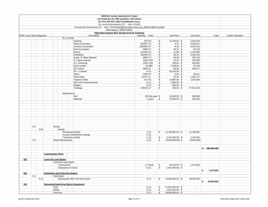
FERC Line # Sub Categories Quantity Units Unit Price Line Price Total Notes / RemarksHigh Devil Canyon RCC Gravity Arch (6 Turbines)
Description
HDR/AEA Susitna Hydroelectric ProjectCost Estimates for 1982 quantities- Alternatives
By: DTA with RCC edits by R&M/Hatch AcresBy: Leanne Andruszkiewicz, EIT Date: 1/25/09
Reviewed By: David Elwood, EIT Date: 1/25/09, Modified by Hatch Acres_kcm_083109; R&M 11/16/09Alternatives- 2008 Dollars
R-1, (19 Mi)Clearing 220 AC 11,416.62$ 2,510,025$ Waste Excavation 552927 CY 9.51$ 5,258,337$ Common Excavation 1083550 CY 8.32$ 9,015,133$ Rock Excavation 2986 CY 28.51$ 85,129$ Borrow 147250 CY 11.88$ 1,749,330$ Subballast 232932 CY 18.15$ 4,226,781$ Grade "A" Base Material 6650 CY 35.45$ 235,729$ D-1 Base material 2400 TON 43.20$ 103,680$ A.C. Surfacing 2200 TON 198.00$ 435,600$ Dock Lumber 16 MBF 1,258.60$ 20,138$ 18" Culvert 6582 LF 68.26$ 449,271$ 36" + Culverts 0 LS 92,160.00$ -$ Fabric 4236 SY 9.00$ 38,121$ Thaw Pipes 13707 LF 95.04$ 1,302,727$ Topsoil & Seed 141 AC 10,800.00$ 1,524,343$ Rail Yard Control Devices 0 LS 1,800.00$ -$ Bridges 0 LS 900.00$ -$ Trackage 134323 LF 350.00$ 47,013,125$
MaintenanceRail 98 Mile-years 10,000.00$ 980,000$ Railhead 7 years 75,000.00$ 525,000$
0.3 Airstrip0.31 Airstrip
Permanent Airstrip 1 LS 12,798,000.00$ 12,798,000$ 9 years maintenance savings 1 LSTemporary Airstrip 1 LD 2,133,000.00$ 2,133,000$
0.4 Saved Maintenance 1 LS (9,554,896.95)$ (9,555,000)$
489,688,469$
Transmission Plant
350 Land and Land Rights Land and Land Rights
Transmission 17 MILE 86,720.00$ 1,474,000$ Substations (4 Sites) 0 LS 2,607,000.00$ -$
1,474,000$ 352 Substation and Switching Station
0.1 Switchyard0.11 Switchyards HDC and Gold Creek 2 LS 14,000,000.00$ 28,000,000$
28,000,000$ 353 Substation/Switching Station Equipment
Ester 0 LS 57,922,800.00$ -$ Willow 0 LS 3,613,020.00$ -$ Knik Arm 0 LS 29,838,300.00$ -$
By DTA; edited by R.HAC Page 15 of 17 Alternative High Devil Canyon RCC
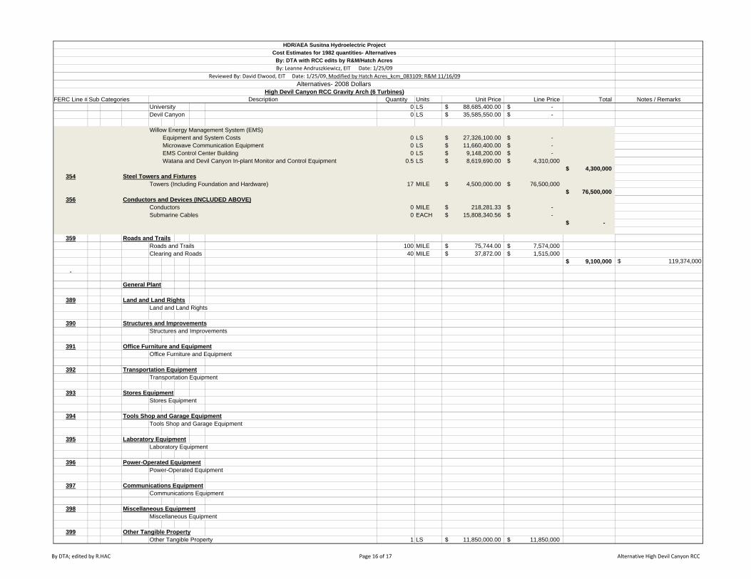
FERC Line # Sub Categories Quantity Units Unit Price Line Price Total Notes / RemarksHigh Devil Canyon RCC Gravity Arch (6 Turbines)
Description
HDR/AEA Susitna Hydroelectric ProjectCost Estimates for 1982 quantities- Alternatives
By: DTA with RCC edits by R&M/Hatch AcresBy: Leanne Andruszkiewicz, EIT Date: 1/25/09
Reviewed By: David Elwood, EIT Date: 1/25/09, Modified by Hatch Acres_kcm_083109; R&M 11/16/09Alternatives- 2008 Dollars
University 0 LS 88,685,400.00$ -$ Devil Canyon 0 LS 35,585,550.00$ -$
Willow Energy Management System (EMS) Equipment and System Costs 0 LS 27,326,100.00$ -$ Microwave Communication Equipment 0 LS 11,660,400.00$ -$ EMS Control Center Building 0 LS 9,148,200.00$ -$ Watana and Devil Canyon In-plant Monitor and Control Equipment 0.5 LS 8,619,690.00$ 4,310,000$
4,300,000$ 354 Steel Towers and Fixtures
Towers (Including Foundation and Hardware) 17 MILE 4,500,000.00$ 76,500,000$ 76,500,000$
356 Conductors and Devices (INCLUDED ABOVE)Conductors 0 MILE 218,281.33$ -$ Submarine Cables 0 EACH 15,808,340.56$ -$
-$
359 Roads and TrailsRoads and Trails 100 MILE 75,744.00$ 7,574,000$ Clearing and Roads 40 MILE 37,872.00$ 1,515,000$
9,100,000$ $ 119,374,000
General Plant
389 Land and Land RightsLand and Land Rights
390 Structures and ImprovementsStructures and Improvements
391 Office Furniture and EquipmentOffice Furniture and Equipment
392 Transportation EquipmentTransportation Equipment
393 Stores EquipmentStores Equipment
394 Tools Shop and Garage EquipmentTools Shop and Garage Equipment
395 Laboratory EquipmentLaboratory Equipment
396 Power-Operated EquipmentPower-Operated Equipment
397 Communications EquipmentCommunications Equipment
398 Miscellaneous EquipmentMiscellaneous Equipment
399 Other Tangible PropertyOther Tangible Property 1 LS 11,850,000.00$ 11,850,000$
By DTA; edited by R.HAC Page 16 of 17 Alternative High Devil Canyon RCC
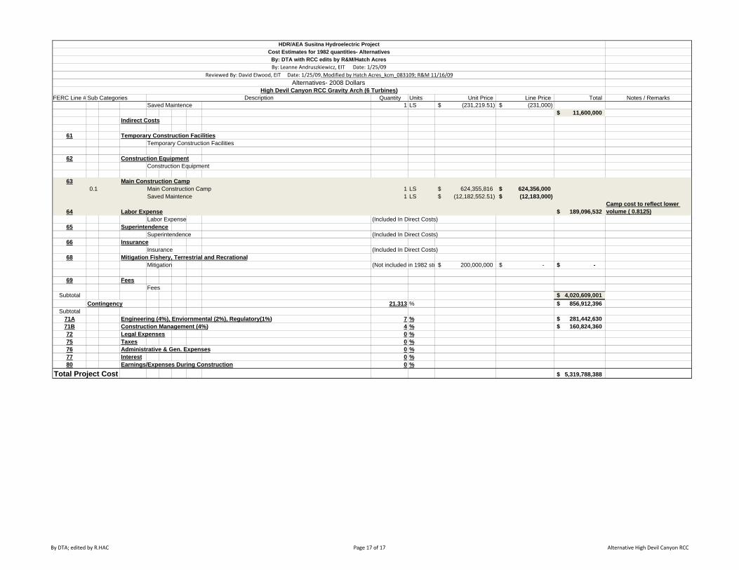
FERC Line # Sub Categories Quantity Units Unit Price Line Price Total Notes / RemarksHigh Devil Canyon RCC Gravity Arch (6 Turbines)
Description
HDR/AEA Susitna Hydroelectric ProjectCost Estimates for 1982 quantities- Alternatives
By: DTA with RCC edits by R&M/Hatch AcresBy: Leanne Andruszkiewicz, EIT Date: 1/25/09
Reviewed By: David Elwood, EIT Date: 1/25/09, Modified by Hatch Acres_kcm_083109; R&M 11/16/09Alternatives- 2008 Dollars
Saved Maintence 1 LS (231,219.51)$ (231,000)$ 11,600,000$
Indirect Costs
61 Temporary Construction FacilitiesTemporary Construction Facilities
62 Construction EquipmentConstruction Equipment
63 Main Construction Camp 0.1 Main Construction Camp 1 LS 624,355,816$ 624,356,000$
Saved Maintence 1 LS (12,182,552.51)$ (12,183,000)$
64 Labor Expense 189,096,532$ Camp cost to reflect lower volume ( 0.8125)
Labor Expense (Included In Direct Costs)65 Superintendence
Superintendence (Included In Direct Costs)66 Insurance
Insurance (Included In Direct Costs)68 Mitigation Fishery, Terrestrial and Recrational
Mitigation (Not included in 1982 stu 200,000,000$ -$ -$
69 FeesFees
Subtotal 4,020,609,001$ Contingency 21.313 % 856,912,396$
Subtotal71A Engineering (4%), Enviornmental (2%), Regulatory(1%) 7 % 281,442,630$ 71B Construction Management (4%) 4 % 160,824,360$ 72 Legal Expenses 0 %75 Taxes 0 %76 Administrative & Gen. Expenses 0 %77 Interest 0 %80 Earnings/Expenses During Construction 0 %
Total Project Cost 5,319,788,388$
By DTA; edited by R.HAC Page 17 of 17 Alternative High Devil Canyon RCC