Survey Directions 011020
32
Page 1 of 32 Revision Date: 011020 SURVEY DIRECTIONS Tasmania Pursuant to the Surveyors Act 2002
Transcript of Survey Directions 011020

Page 1 of 32
Revision Date: 011020
SURVEY DIRECTIONS Tasmania
Pursuant to the Surveyors Act 2002

Page 2 of 32
Revision Status Revision Date: 011020
Part / Schedule Division Heading Last Revision Date Table of Contents 011020 Part 1 Preliminary 011020 Part 2 General Provisions 011020 Part 3 Surveys of Land Division 1 Vector and Coordinate Accuracy Requirements 011020 Division 2 Boundaries 011020 Division 3 Plans and Survey Notes 011020 Division 4 Surveys with Modified Requirements 011020 Division 5 Marking Requirements 140918 Schedule 1 Types of Survey Controlled by Directions 010105 Schedule 2 Descriptions, Abbreviations and Symbols 011020 Schedule 3 Party Walls 010308 Schedule 4 Electricity Wayleave Identification Surveys 010105 Schedule 5 Form of Survey Marks 101214
Page 3 of 32
Table of Contents Revision Date: 011020
Part / Schedule Division - Heading Section Section Heading 1 - Preliminary 1 - 1 Short Title 2 Commencement 3 Purpose and Scope 4 Interpretation 2 – General Provisions 1 - 1 Duties and Responsibilities of Surveyors 2 Coordinate and Bearing Datum 3 Survey Equipment and Methods 4 Survey Records 5 Access to Survey Records 6 Requisition to Amend Survey 7 Alteration of Survey Notes 8 Buried Survey Marks 9 Permanent Mark Reporting Requirements 10 Application to Vary Requirements of the
Directions 3 – Surveys of Land 1 - Vector and Coordinate
Accuracy Requirements 1 Co-ordination Requirements
2 Vectors and Coordinates 3 Vector Accuracy Requirements 2 - Boundaries 1 New Boundaries 2 Reinstatement of Boundaries 3 Existing Survey Data 3 - Plans and Survey Notes 1 Lodgement of Plans and Survey Notes 2 Survey Notes and Reports 3 Compiled Survey Plans 4 – Surveys with Modified
Requirements 1 Easement Surveys
2 Survey Requirements for Strata Plans 3 Electricity Wayleave Identification Surveys 5 – Marking Requirements 1 Survey Marks 2 Marking of Boundaries 3 Replacement of Survey Marks 4 Reference Marks 5 Obliteration Of Incorrect Survey Marks 6 Unregistered Boundary Marks 7 Form of Survey Marks Schedule 1 Types of Survey Controlled by Directions Schedule 2 Descriptions, Abbreviations and Symbols Schedule 3 Schedule 4
Party Walls Electricity Wayleave Identification Surveys
Schedule 5 Form of Survey Marks
Page 4 of 32
SURVEY DIRECTIONS, Tasmania
I, Michael Giudici, Surveyor General for the State of Tasmania, issue the following directions under section 15 of the Surveyors Act 2002. 011020 Michael Giudici Surveyor General
PART 1 – PRELIMINARY Revision Date: 011020
1.1.1 Short Title These Directions may be cited as the Survey Directions, Tasmania. 1.1.2 Commencement The commencement date for each Part, Division or Schedule is the most recent Revision Date recorded for that Part, Division or Schedule. 1.1.3 Purpose and Scope The purpose of these Directions is to set the technical specifications and standards to be observed in the conduct of surveys made for a statutory purpose, as prescribed in section 15 of the principal Act. The types of survey currently controlled by these Directions are listed in Schedule 1. 1.1.4 Interpretation These definitions are in addition to those in the principal Act. In these Directions, except in so far as the context or subject matter otherwise indicates or requires – “abuttal” refers to any region which from a plan or description appears to abut upon and share a common boundary with the land in question; “accuracy” means the degree of conformity with the true value; “AUSPOS” means the online GPS data processing facility provided by Geoscience Australia; “CORS”, being the abbreviation for Continually Operating Reference Station, refers to any continuously operating stand-alone or networked GNSS ground station(s), for which position data is available to the end user either as a real-time correction service or for post processing; “corner” means the point at which a documented boundary terminates, changes direction, or intersects another boundary;
Page 5 of 32
"EDM" refers to electromagnetic distance measuring equipment. "error" means the difference between a stated value and the true value; “Geocentric Datum of Australia 2020”, abbreviated as GDA2020, has the same meaning as that contained in the Determination made as to the Recognized-value Standard of Measurement of Position under section 8A of the National Measurement Act 1960 (Cwth); “Global Navigation Satellite Systems’, abbreviated as GNSS, is the generic term for satellite navigation and positioning systems; “identification survey” means a survey required for the purpose of locating and identifying a particular title or boundary, including the relationship of improvements to that title or boundary, but not requiring the boundary to be marked; “land” has the meaning given by the Surveyors Act 2002; “local coordinated mark” means a survey mark coordinated on the MGA2020, other than a boundary mark, established in the vicinity of the land under survey. “Map Grid of Australia 2020”, abbreviated as MGA2020, means the official Australian Universal Transverse Mercator projection of GDA2020, as defined in the Geocentric Datum of Australia 2020 Technical Manual of the Intergovernmental Committee on Surveying and Mapping; “natural feature” means a river, water course, shore, cliff, watershed or any natural topographic feature that is suitable for use as a boundary; “permanent mark” is any mark adopted as a permanent mark under section 14 of the Survey Coordination Act 1944; “plan” includes every plan made for the purpose of lodgement with a registering authority; “positional uncertainty”, abbreviated as PU, is the uncertainty of the coordinates of a point, in metres, at the 95% confidence level, with respect to the GDA2020, expressed in terms of the horizontal circular confidence region described in the Standard for the Australian Survey Control Network Special Publication 1 of the Intergovernmental Committee on Surveying and Mapping; “principal Act” means the Surveyors Act 2002; “Registered Land Surveyor” and “Registered Surveyor” have the meanings given by the Surveyors Act 2002; “Regulation 13” means certification under the National Measurement Regulations 1999 displaying the station coordinate and its uncertainty on an applicable Australian national datum issued by Geoscience Australia. “reinstatement of a boundary” refers to the positional re-establishment and marking of an existing boundary; “re-mark (or repeg) survey” means a survey required only for the purpose of reinstating an existing title or boundary , including marking, directly or by the use of reference marks, that title or boundary on the ground,;

Page 6 of 32
“survey” has the meaning given by the Surveyors Act 2002; “Survey Control Marks Database”, abbreviated as SURCOM, means the database of permanent marks held by the Office of the Surveyor General; “survey mark” has the meaning given by the Surveyors Act 2002, being a boundary mark, reference mark, traverse mark or permanent mark taking the form more particularly prescribed in section 3.5.7. “survey records” comprise the documents necessary to record adequately all aspects of a survey, including the survey notes and any plan drawn from those survey notes; “Surveyor General” means the person appointed as Surveyor General under section 3A of the Survey Co-ordination Act 1944.
Page 7 of 32
PART 2 – GENERAL PROVISIONS Revision Date: 011020
This Part defines the requirements for the undertaking of any of the types of survey listed in Schedule 1. In this part the term “surveyor” means any person responsible for undertaking such a survey. 2.1.1 Duties and Responsibilities of Surveyors For any survey upon which a surveyor is engaged, the surveyor must – (a) ensure that the survey is performed in accordance with these Directions; and (b) where no express provision is made in these Directions, comply with nationally recognised survey practice standards; and (c) obtain and consider all the information and measurements necessary to prove the survey; and (d) have regard to the interests and responsibilities of the Crown and the community. 2.1.2 Coordinate and Bearing Datum
2.1.2.1 The horizontal datum for bearing and coordinates to be adopted for all surveys of a type listed in Schedule 1 must be the GDA2020 unless other provision is made in these Directions. All bearing and coordinate values must be expressed in terms of the MGA2020. 2.1.2.2 The datum for bearings and coordinates recorded on plans and/or survey notes must be clearly identified. 2.1.2.3 The MGA2020 coordinates for a survey must be determined specifically for that survey and:
(a) in the case where a previously established survey mark is used as the origin of the MGA2020 coordinates it must be a permanent mark held in SURCOM, or (b) in the case where a CORS network is used as the origin of the MGA2020 coordinates it must be derived from a CORS network whose stations have Regulation 13 certified coordinates, or (c) in the case where a single CORS base station is used as the origin of the MGA2020 coordinates it must be a station with Regulation 13 certified coordinates, or (d) in the case where an AUSPOS solution is used as the origin of the MGA2020 coordinates the AUSPOS report must indicate that a reliable solution has been achieved.
2.1.2.4 The bearing datum for a survey must be determined specifically for that survey and:
(a) in the case where previously established survey marks are used for the bearing datum the marks must be permanent marks held in SURCOM and the marks that are reasonably accessible to the survey that provide the most accurate determination of bearing must be used, or (b) in the case where GNSS is used to derive the bearing datum the method of GNSS measurement must be specified.

Page 8 of 32
Explanatory Note Where MGA2020 coordinates and bearing determined per clauses 2.1.2.3 and 2.1.2.4 confirm existing MGA2020 coordinates and bearing datum from a prior survey it is acceptable to use those prior surveyed values provided a statement is added to the survey notes that the MGA2020 coordinates and bearing datum have been confirmed by measurements that satisfy clauses 2.1.2.3 and 2.1.2.4. 2.1.2.5 For the purpose of estimating the positional uncertainty of derived coordinates, the positional uncertainty of MGA2020 coordinates:
(a) of permanent marks held in SURCOM, is the value provided in the SURCOM Survey Control Mark Summary for the GDA2020 datum;
(b) derived from a satisfactory AUSPOS solution is the positional uncertainty provided in the AUSPOS report, at the 95% confidence level; (c) derived from a CORS solution, is the average quality value indicated by the GNSS receiver over two occupations no less than 20 minutes apart, adjusted to 95% confidence level (= A), increased to allow for the positional uncertainty of the CORS base station coordinates as follows: √. (A2 + 0.0122)
2.1.3 Survey Equipment and Methods
2.1.3.1 A surveyor must carry out surveys with such equipment and by such methods as are capable of readily achieving the purpose of the survey and satisfying the requirements prescribed by these Directions. 2.1.3.2 In carrying out a survey a surveyor must apply such checks and tests as are necessary to ensure that the requirements prescribed by these Directions are achieved.
2.1.3.2.1 Where CORS using a single base station is used for datum acquisition over a distance of greater than 30 kilometres, connection to the closest reasonably accessible mark with a GDA2020 PU of 0.050 or better permanent mark in SURCOM (designated the ‘SURCOM Check Mark’) suitable to provide redundancy of measurement must be made, and the comparison and means of bearing datum acquisition reported in the survey notes.
2.1.3.3 To enable the maintenance of standards of survey accuracy required by these Directions, a surveyor must ensure that all equipment used in carrying out a survey is kept in good order and adjustment and that it is regularly calibrated and standardised by comparison with a National Reference Standard of Length verified under the National Measurement Act 1960. Explanatory Notes: (1) Recognising the difficulty of standardising GNSS equipment, it is acceptable to 'standardise' this equipment by comparison with distances measured with an EDM that has itself been standardised in accordance with sub-section 2.1.3.3, and to validate GNSS equipment operation by comparison, on a regular basis, with those distances, or with distances calculated between permanent marks in SURCOM with a GDA2020 PU of 0.03 or better. (2) It is recommended that surveyors maintain appropriate records of calibrations and standardisations made on their survey equipment.

Page 9 of 32
2.1.4 Survey Records
2.1.4.1 Any plan that is required to be made as a result of a survey must – (a) be prepared in a manner and form determined by the relevant registering authority; and (b) be lodged with that registering authority; and (c) where required by the Surveyor General or registering authority, be accompanied by survey
notes.
2.1.4.2 Any survey notes accompanying or forming part of a plan under sub-section 2.1.4.1 must- (a) contain the information and measurements collected by the surveyor in the course of a
survey; and (b) be prepared in a manner and form set out in these Directions; and (c) where required by section 26 of the principal Act, be certified in accordance with the Act; and (d) subject to section 24 of the principal Act and section 2.1.6, not be altered after they, or the
plan or document based on them, have been approved by a registering authority.
2.1.4.3 A plan and survey notes lodged with a registering authority under this section and accepted by the registering authority shall, upon that acceptance – (a) constitute the public record of the survey to which the plan and survey notes relate; and (b) become the property of the Crown.
2.1.4.4 All lengths or distances shown on any plan or survey notes must be horizontal lengths or distances, measured or calculated at the terrain mid-height of the location of the measurement.
2.1.5 Access to Survey Records The survey records of any public authority within the meaning of the Survey Co-ordination Act 1944 must be available to a surveyor so far as may be necessary to enable the surveyor to acquire information for the purposes of undertaking a survey.
2.1.6 Requisition to Amend Survey
2.1.6.1 A registering authority may requisition a surveyor to amend a survey or survey records or to supply such additional information as the registering authority deems necessary to enable the survey or survey records to be completed in accordance with these Directions. 2.1.6.2 Upon receipt of a requisition from a registering authority under sub-section 2.1.6.1, a surveyor must respond to the requisition within a period of one month after the date of issue of the requisition or within such period as the registering authority may determine.
2.1.7 Alteration of Survey Notes
2.1.7.1 Subject to section 24 of the principal Act, survey notes lodged with a registering authority under section 2.1.4 must not be altered without the written consent of the surveyor certifying the survey. 2.1.7.2 A written consent referred to in sub-section 2.1.7.1 must be included with, and form part of the survey notes of the survey.
Page 10 of 32
2.1.8 Buried Survey Marks
2.1.8.1 A Registered Surveyor may break up the surface of any land, whether paved or not, to the extent necessary to uncover a survey mark that is believed to be buried under the surface.
2.1.8.2 A Registered Surveyor must manage any damage caused in searching for survey marks in accordance with section 28 of the principal Act.
2.1.9 Permanent Mark Reporting Requirements
A Registered Surveyor discovering an irregularity in the position of a permanent mark, or that a permanent mark has been destroyed, removed or damaged, must comply with the reporting requirements of section 16 of the Survey Co-ordination Act 1944 within one month of such discovery being made. 2.1.10 Application to Vary Requirements of the Directions Where a surveyor demonstrates to the satisfaction of the Surveyor General prior to lodgement of a survey that, in the case of that survey a particular requirement of the Directions is not justified, the Surveyor General has discretion to modify or waive such requirements for that survey.

Page 11 of 32
PART 3 – SURVEYS OF LAND This part applies to all surveys that determine the boundaries to a title or an estate or interest in land requiring a plan of survey to be lodged with a registering authority and /or boundary marks to be placed. For the purpose of this Part “land surveyor” has the same meaning as Registered Land Surveyor. Division 1 - Vector and Coordinate Accuracy Requirements
Revision Date: 011020
3.1.1 Coordination Requirements
3.1.1.1 Every survey of land must have a minimum of two corners coordinated on the MGA2020. Additional corners must be coordinated such that no coordinated corner is separated from another coordinated corner by more than 1 km measured along the external perimeter of the survey. Coordinated corners must be evenly spread around the external perimeter of the survey and the coordinates recorded in the survey notes. 3.1.1.2 Where a GNSS connection to a mark held in SURCOM is used as the origin of the MGA2020 coordinates and the vector connection is not documented, or an AUSPOS solution is used as the origin of the MGA2020 coordinates, a local coordinated mark must be established at the point of the GNSS observation. To the extent possible, consistent with good GNSS survey practice, this mark should have the attributes of a reference mark in accordance with section 3.5.4. 3.1.1.3 Every survey for which the whole of the lot(s) under survey fall within the distance of a permanent mark shown in column A must be coordinated with a positional uncertainty no more than that shown in column B.
Case
A
Proximity of permanent mark with GDA2020 coordinates with a PU of 0.050 or better
B
Maximum allowable positional uncertainty
1 less than 1 km 0.1 metres
2 less than 5 km, but excluding those less than 1 km.
0.3 metres
3 All other surveys 0.5 metres
Page 12 of 32
3.1.2 Vectors and Coordinates
3.1.2.1 Where the method of survey creates or identifies bearing and vector misclosures, these must be distributed throughout the survey in a systematic adjustment prior to documentation in the survey notes. 3.1.2.2 All coordinates recorded in survey notes must be mathematically consistent with the linear dimensions shown subject to the normal application of Combined Scale Factor (CSF). 3.1.2.3 Individual coordinates must be documented together with an estimate of their positional uncertainty. The estimate must be mathematically consistent with the positional uncertainty of the origin mark(s) and the survey method from which the estimate has been determined.
Explanatory Note: A consequence of this section is that, in relation to documented bearings and distances between survey marks and coordinates of survey marks, all bearings are assumed to be recorded to the nearest second of arc and all distances and coordinates to the nearest 0.001 metre, irrespective of whether minutes or seconds of arc or three decimal places of a metre are actually shown. 3.1.3 Vector Accuracy Requirements
3.1.3.1 The maximum allowable angular error in any MGA2020 bearing recorded between survey marks shown in survey notes is: (a) 2’ of arc; or (b) the angular error that produces a displacement at the end of the line of 0.025 metres; whichever is the greater.
3.1.3.2 The maximum allowable error in any distance documented or calculated between survey marks shown in survey notes is 1:10,000 of the distance or 0.025 metres, whichever is the greater.
Explanatory Note: Practically, error as it relates to sub-section 3.1.3.2 is the difference between a distance documented in survey notes or a distance calculated from survey notes and the true distance (approximated by an accurate direct measurement of the relevant distance). Surveyors should test their surveys in the areas most likely to fail this requirement and include such test measurements into the survey adjustment if necessary to enable the survey to meet the requirement.
Page 13 of 32
Division 2 – Boundaries Revision Date: 011020
3.2.1 New Boundaries
3.2.1.1 Where it is necessary to create a new boundary to enable a title or an estate or interest in land to be registered, the boundary must be surveyed and the corners and boundary lines marked in accordance with the provisions of these Directions. 3.2.1.2 All evidence of the current physical extent of occupation along, adjoining or immediately adjacent to any new boundary must be recorded in the survey notes. 3.2.1.3 Where boundaries can be adequately determined without marking the corners and boundary lines, and marking the boundaries would serve no useful purpose, the corners and boundaries may be left unmarked if – (a) approval has been received from the Surveyor General prior to lodgement of the survey; and (b) sufficient survey marks are placed to permit the corner or boundary to be readily established
on the ground; and (c) the survey accuracy of the unmarked boundary is the same as for the whole survey; and (d) the reasons for not marking a boundary or corner are stated in the survey notes.
3.2.1.4 Where a natural feature is to be adopted as a boundary, it must be surveyed by a method that will locate the natural feature to an accuracy appropriate to the purpose and circumstances of the survey and an unambiguous description of the feature adopted must be included in the survey records.
3.2.2 Reinstatement of Boundaries
3.2.2.1 A land surveyor must ascertain and report unambiguously on the origin, nature, position, and age (where not evident from the attributed origin) of survey marks, buildings, fences, and other features that are evidence of previously established boundaries being resurveyed. Such features include all evidence of occupation and other interests in the vicinity of surveyed boundaries. 3.2.2.2 Reports as to the nature and position of evidence must include any uncertainty as to the stability of such evidence or its relativity to original position, and its suitability in defining the exact location of an existing boundary. 3.2.2.3 A survey mark must not be placed on a previously surveyed boundary unless satisfactory evidence is found from which that portion of the boundary can be reinstated. For evidence to be proved satisfactory the search for both primary and secondary evidence must be extended as far as is necessary to prove that any additional evidence would not materially alter the reinstatement if it was found to be inconsistent with the evidence adopted.
Page 14 of 32
3.2.2.4 In reinstating boundaries, the intention expressed in the instruments providing for their creation must be determined from the best evidence that the nature of the case admits. A guiding principle is that most effect is to be given to that evidence about which there is least likelihood of a mistake having originally been, or now being made. Where there is conflicting evidence, the order of priority generally assigned to such evidence by the courts is: 1. Natural boundaries 2. Monuments creating the boundary 3. Long undisputed occupation 4. Abuttals 5. Measurement Explanatory Note: Survey marks placed in the process of reinstating a boundary form secondary evidence of the original surveyed boundary. Where a land surveyor’s boundary reinstatement decisions deviate from this hierarchy, the facts and reasoning must be clearly reported in the survey notes. 3.2.2.5 If a land surveyor searches for but is unable to locate particular evidence, that fact must be recorded in the survey notes in accordance with Schedule 2. 3.2.2.6 If, in reinstating a boundary, a land surveyor can positively establish from the plan and survey notes of a previous survey and the evidence derived from the reinstatement that a boundary mark has been incorrectly placed in the previous survey, the land surveyor making the reinstatement may re-set the boundary mark in accordance with the previous survey if –
(a) the position of any buildings, fences, walls, or other permanent improvements adversely
affected by this determination of the boundary are recorded in the survey notes; and (b) the consent of all owners of the titles affected is obtained; and (c) the discrepancy and the action taken are recorded in a written report accompanying the
survey notes. 3.2.2.7 A land surveyor must mark reinstated boundaries in accordance with the provisions of these Directions.
3.2.2.8 Where an existing boundary is to disappear as a consequence of the creation of a new boundary, a land surveyor may elect not to mark that boundary provided the reason for not marking the boundary and the basis for its reinstatement are fully recorded in the survey notes.
3.2.2.9 A re-mark survey must be carried out in accordance with the provisions of these Directions.
3.2.3 Existing Survey Data
3.2.3.1 A land surveyor may adopt one or more existing boundaries as part of a lot under survey, without reinstating those boundaries, if – (a) the boundaries have been previously surveyed and marked in accordance with the statutory
requirements at the time of that survey and are described in an existing registered survey; and
(b) the boundary dimensions are adopted from the survey marking those boundaries and, subject to a single consistent rotation of bearings to MGA2020 where necessary, comply with the vector accuracy requirements of section 3.1.3; and

Page 15 of 32
(c) the land surveyor is satisfied that the adopted boundaries are adequately identified on the ground for the purpose of the survey and provides a report in the survey notes of the nature of that boundary identification; and
(d) satisfactory connections to original survey marks are made at each end of the adopted section of boundary; and
(e) the adopted boundaries are clearly identified in the survey notes.
3.2.3.2 Adopted boundary dimensions must be integrated into the survey in accordance with section 3.1.2.1. Where adopted boundary dimensions are to be adjusted, the following requirements must be met: (a) the adjustment of the adopted bearings and lengths must be systematic in nature. (b) the adjusted bearings must be MGA2020 bearings that comply with section 3.1.3.1. (c) the difference between any adopted length before and after adjustment must not exceed
1:10,000 of the adopted length or 0.025 metres, whichever is the greater. 3.2.3.3 Where boundaries are adopted, a comparison of the vectors between the terminal marks of the adopted portion of boundary calculated from the adopted dimensions and adjusted dimensions must be documented in the survey notes.
3.2.3.4 Data that is derived from a previous survey other than a survey of land may be used by a land surveyor for the following purposes – (a) determining a boundary; or (b) determining compliance with accuracy requirements and/or calculating coordinates; or (c) as evidence of the position of occupational, topographical or cultural features; providing – (d) the new survey is directly connected to the previous survey and the derived dimensions meet the requirements of Part 3 Division 1; and (e) the survey notes clearly identify the derived data, origin and nature of that survey; and (f) the land surveyor accepts responsibility for the correctness of the data used and any resulting calculated vectors and coordinates, and for the adequate marking of any boundary so defined. Explanatory Note on Adoption and Compilation: The term “adopt” is generally used to indicate which evidence a land surveyor has accepted as being 'the best evidence that the nature of the case admits'. It is recognised that circumstances may exist where a land surveyor is satisfied that existing boundaries of a lot under survey are adequately identified on the ground for the purpose of the survey. In this circumstance sub-section 3.2.3.1 authorises the land surveyor to adopt existing boundary dimensions in lieu of reinstating those boundaries and the adopted boundary dimensions are used directly in the calculation of the area of a lot under survey. Adoption involves incorporation of the adopted dimensions into the survey being undertaken, requiring the adopted dimensions to comply with the current accuracy requirements. Adopted boundaries are NOT compiled boundaries and should not be identified as compiled on the plan of survey. A lot, or part of a lot being a balance of title, may be compiled onto a plan of survey in accordance with section 3.3.3 . Compiled boundary dimensions are not incorporated into the survey and need only comply with the accuracy requirements at the time of the original survey.

Page 16 of 32
Division 3 – Plans and Survey Notes Revision Date: 011020
3.3.1 Lodgement of Plans and Survey Notes
3.3.1.1 A land surveyor must – (a) prepare a plan and survey notes in respect of every survey made under sections 3.2.1 and
3.2.2; and (b) subject to sub-section 3.3.1.3, lodge the plan or a copy of the plan, together with the survey
notes or copy of the survey notes, in the office of the appropriate registering authority within a period of 6 months after the placement of any survey mark defining a boundary.
3.3.1.2 The Surveyor General may, on the application of a land surveyor, extend the period of lodgement of a particular survey to such period as the Surveyor General thinks necessary. 3.3.1.3 Sub-section 3.3.1.1 does not apply where a land surveyor destroys or causes to be destroyed all boundary marks of the survey before the expiration of the period referred to in that sub-section. Explanatory Note: The purpose of this clause is only to allow flexibility for a Land Surveyor to remove boundary marks before they are relied upon for any purpose. 3.3.1.4 Where a survey is required only for the purpose of re-marking an existing boundary or boundaries, the plan and survey notes may be combined into one document.
3.3.2 Survey Notes and Reports
3.3.2.1 Any survey notes required to be made as part of a survey of land from which a plan is to be produced, or accompanying or forming part of a plan under sub-section 2.1.4.1 must - (a) describe the bearing and coordinate datum adopted and its origin(s), whether derived from
permanent marks in SURCOM, an AUSPOS report or CORS observation, together with (where applicable) the connection to and coordinates of any origin mark(s), and in addition where a GNSS connection from a coordinate origin is used to coordinate a survey and the connection is not documented, document the coordinates and estimate of positional uncertainty of the local coordinated mark within the surveyed area; and
(b) report the combined scale factor applicable to the survey, and in addition where by virtue of large height difference or extent of an MGA2020 connection or survey area a single combined scale factor is inappropriate, report how multiple factors have been applied to the survey; and
(c) document coordinates for selected lot corners, together with an estimate of their positional uncertainty, in accordance with Part 3 Division 1; and
(d) show in diagrammatic form and dimension all boundaries and connections between boundary marks and their related traverse and reference marks, and sufficient additional connections or coordinates to provide the spatial relationship between the boundaries surveyed and all survey marks found and placed; and
(e) accurately, completely and unambiguously describe all survey marks included in the survey in accordance with Schedule 2; and
(f) describe all the evidence, whether physical or documentary, on which the determination of boundaries to a title or an estate or interest in that land is based; and

Page 17 of 32
(g) describe any evidence of conflicting interests in that land affected by the boundary determination; and
(h) describe the adoptions made and, where not readily evident from the survey notes without further explanation, report on the methodology or reasoning used in the reinstatement of boundaries; and
(i) report the dates of commencement and completion of the survey; and (j) report the name of any CORS, single or networked, used in the survey; and (k) show MGA2020 north orientation relative to the page; and (l) uniquely identify, by number or letter or combination thereof in brackets or otherwise
enclosed, every survey mark placed or adopted; and (m) record all the information required to produce the plan, including the purpose of the survey,
except that references to relevant registered survey documentation recorded on the plan and details recorded in the title block of that plan (other than folio references) need not be duplicated in the survey notes; and
(n) include a reference to any variations in requirements approved by the Surveyor General in relation to the survey.
(o) Where requested by the Surveyor General in writing, provide with each survey lodged a completed checklist in a form authorised by the Surveyor General.
Explanatory Notes: When referring to mark numbers on previous surveys, the suggested form is per the following example: (SP140121/25). In relation to clause 3.3.2.1 (d), calculated ties should be documented across long narrow lots at reasonable intervals to clarify the spatial relationship of the two sides. 3.3.2.2 In survey notes, linear and point dimensions and descriptions must be unambiguously documented alongside the relevant feature, or in close proximity if space does not permit this. Tables may be used only where space cannot be created for individual annotations adjacent to the relevant features and must be located so as to be visually associated with those features. 3.3.2.3 A land surveyor must disclose in survey notes any discrepancy or doubt associated with any other survey, together with any other information that will enable the accuracy and reliability of a boundary delineation or reinstatement made in that survey to be assessed. 3.3.2.4 Where a land surveyor undertaking a survey finds any significant differences in measurement between that survey and any other survey, the land surveyor must document those differences in accordance with sub-section 3.3.2.3 and report them to the Surveyor General.
3.3.3 Compiled Survey Plans
3.3.3.1 A land surveyor may compile a plan in part or total using original dimensions describing boundaries from existing registered surveys where – (a) the compiled boundaries comprise the whole of a lot, or the balance lot of a title under
survey; and (b) all the boundaries used in the compilation have been previously surveyed and marked in
accordance with the statutory requirements at the time of the survey; and (c) the information and particulars shown on the plan are sufficient to enable a registering
authority to accept the plan for lodgement.
Page 18 of 32
3.3.3.2 A land surveyor must – (a) endorse a plan made pursuant to sub-section 3.3.3.1 with words advising of the compiled
nature of all or part of the plan and the origin of the compiled dimensions; and (b) clearly identify as compiled any such dimensions, including any lengths being the balance of
original boundary lengths, shown in survey notes; and (c) show satisfactory connections in survey notes to original survey marks at each intersection of
surveyed and compiled sections of boundary. 3.3.3.3 Compiled boundary dimensions are not subject to Part 3 Division 1 and must not be
altered from the original or used for mathematical calculations.
Page 19 of 32
Division 4 – Surveys with Modified Requirements Revision Date: 011020
3.4.1 Easement Surveys
3.4.1.1 A land surveyor must obtain sufficient information to ensure that the position of an easement under survey can be related to any continuation of the easement through adjoining properties. 3.4.1.2 A land surveyor must perform any easement survey in accordance with the provisions of these Directions except that – (a) the easement boundaries and corners other than title boundary intersections may be left
unmarked if the land surveyor is satisfied that there is no other requirement to mark them; and
(b) every intersection with title boundaries (including road boundaries) is marked on at least one easement boundary, or sufficient reference marks placed to enable each intersection position to be readily marked.
3.4.1.3 New and existing easements crossing a lot under survey, documented on a plan or survey notes, must detail sufficient dimensions along any boundary intersected to allow ready identification of the position of the easement at the intersection Explanatory Note: Unmarked easement corners should not use the symbol for boundary marks and need not be documented as a ‘No Mark’.
3.4.2 Survey Requirements for Strata Plans
Note: this section applies only to strata plans made under the Strata Titles Act 1998, not to surveys defining the external boundaries of a site. 3.4.2.1 A land surveyor must produce a strata plan from field survey of sufficient detail and accuracy to enable the lot boundaries on the strata plan to be accurately described and correctly drawn at the scale of the strata plan. 3.4.2.2 The accuracy of any length or distance shown on a strata plan must comply with the accuracy requirements of sub-section 3.1.3.2. 3.4.2.3 Where an offset is to be shown on a strata plan from a building to an external boundary of the site, the location of the external boundary must be determined in accordance with these Directions. 3.4.2.4 A land surveyor must not make a certification about the spatial relationship between the building(s) erected on the site of a strata plan and the external boundaries of the site unless that spatial relationship has first been verified by field survey. 3.4.2.5 Any open lot boundary that is not in the form of a straight line terminating at a site boundary or substantial and durable constructed feature (being part of the site infrastructure) must be surveyed, marked, and recorded in survey notes (lodged with the strata plan) in accordance with the provisions of these Directions, excepting that: (a) coordination of boundaries is not required; and
Page 20 of 32
(b) any bearings shown on the survey notes must be on the bearing datum of the survey defining the external boundaries of the site, or on MGA2020 bearing with the rotation to that survey documented in the survey notes.
3.4.2.6 A survey made in accordance with sub-section 3.4.2.5 must be connected to an external boundary of the site.
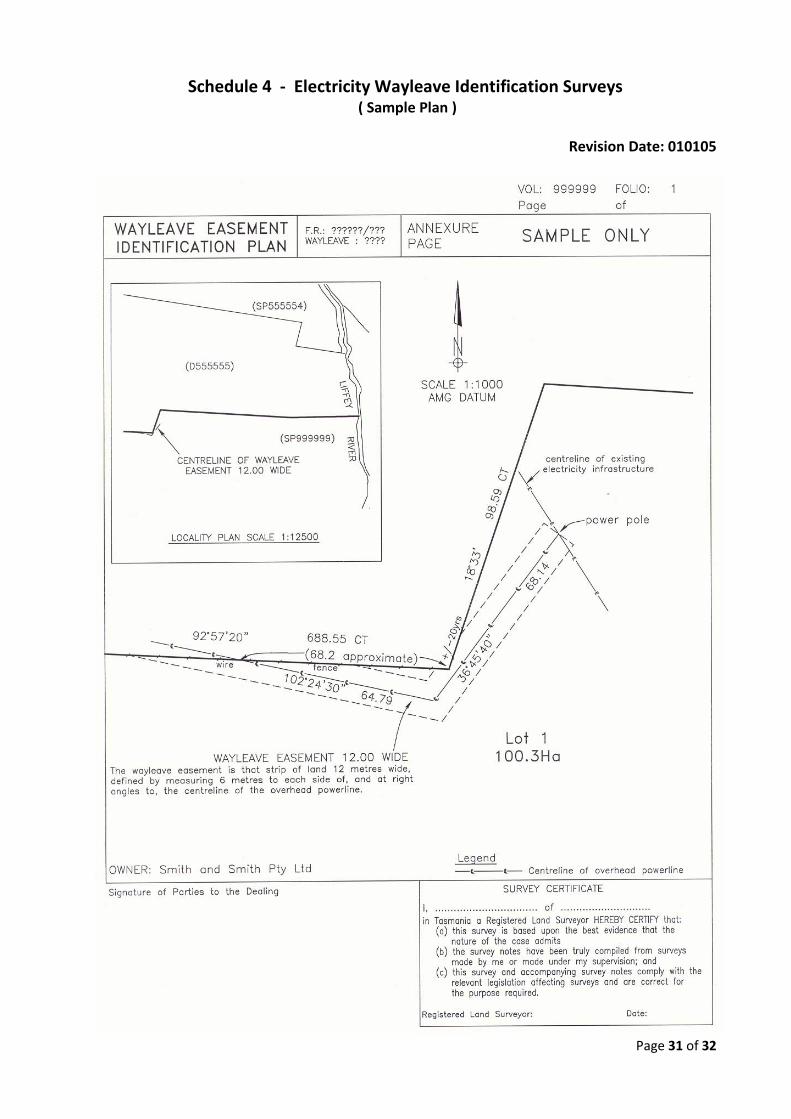
3.4.3 Electricity Wayleave Identification Surveys
3.4.3.1 Where a wayleave easement is to be registered over an existing overhead powerline, the survey may be carried out as an identification survey on the basis that the overhead powerline is accepted as the monumentation fixing the position of the easement. Such surveys may be undertaken for the purpose of – (a) identification of an unregistered wayleave easement in gross for formal registration on title
pursuant to the Electricity Wayleaves and Easements Act 2000; or (b) creation of a new electricity wayleave easement in gross. 3.4.3.2 In undertaking an identification survey for an electricity wayleave easement, a land surveyor must – (a) produce a Wayleave Easement Identification Plan incorporating limited survey notes, in accordance with the sample plan in Schedule 4, for lodgement with the registering authority; and (b) undertake sufficient survey work to ensure that the title boundaries and wayleave easement shown on the plan, and their relationship, is correct; and (c) describe any evidence of previously established boundaries found on title boundaries in the vicinity of the intersection with the wayleave easement, in accordance with sub-section 3.2.2.1; and (d) annotate those dimensions on the plan not in conformance with Part 3 Division 1 as approximate; and (e) ensure that the easement being created is documented parallel to and centred on the constructed overhead powerline.
3.4.3.3 Where an electricity wayleave identification survey reveals doubts as to the true relationship between the wayleave easement and adjacent title boundaries, an easement survey must be undertaken in accordance with section 3.4.1 . 3.4.3.4 The survey of all other electricity infrastructure easements must conform to the requirements of section 3.4.1 .
Explanatory Note: Identification surveys, other than Electricity Wayleave Identification Surveys, are not surveys of land as defined in the Surveyors Act 2002.
Page 21 of 32
Division 5 – Marking Requirements Revision Date: 140918
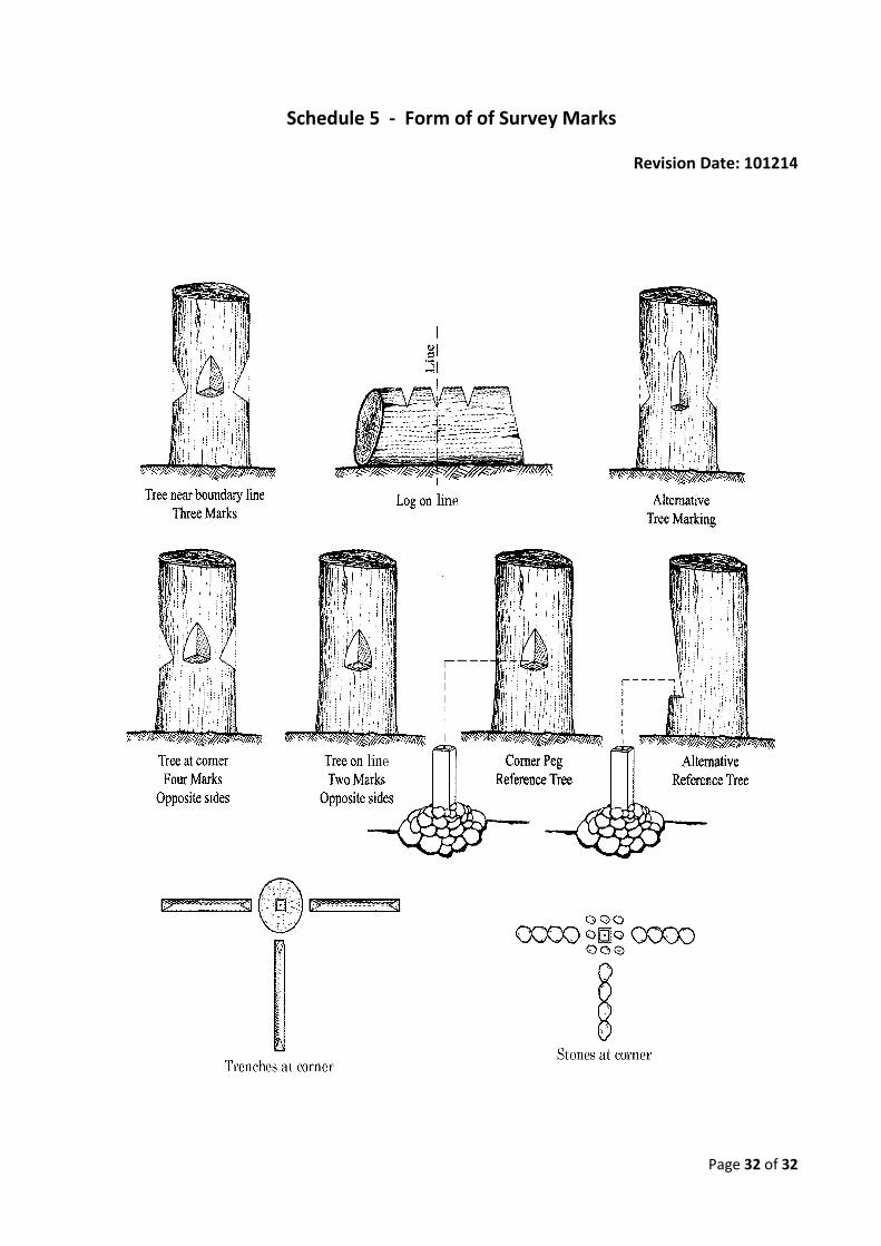
3.5.1 Survey Marks Any survey marks specified under this Division must be placed in accordance with the provisions of these Directions, take one of the forms specified in this Division, and be described in survey notes in accordance with Schedule 2.
3.5.2 Marking of Boundaries
3.5.2.1 Any surveyed boundary, unless otherwise stipulated in these Directions, must be marked in a permanent manner, ensuring that the boundary is readily and unambiguously discernible on the ground at the completion of the survey. 3.5.2.2 Unless otherwise stipulated in these Directions, a boundary mark must be placed at every corner of surveyed boundaries. In rural areas a corner boundary mark must be secured with a pile of stones, where these are available.
3.5.2.3 Where a physical impediment exists at a corner preventing the placement of a boundary mark at that corner, a boundary line mark must be placed along one or more boundaries terminating at that corner, as near as practicable to the corner; and the survey notes must report – (a) its position and description, and (b) the reason for not marking the actual corner. 3.5.2.4 The line of a boundary between corners, if not sufficiently defined by a fence, hedge, wall, natural feature, or some other similar feature, must be defined and made clearly evident by the placement of boundary marks (other than marked trees or logs) on the line.
Note: For the purpose of line marking of boundaries in rural areas, but not marking of corners, the line of a boundary may be considered to be clearly evident where a fence, hedge, wall or other similar feature falls within 0.5 metres of the boundary as defined. An offset distance between the line of the boundary and feature should be documented in the survey notes at appropriate intervals. 3.5.2.5 A boundary in bushland, if not able to be made clearly evident by placement of boundary line marks alone, must in addition be made clearly evident by – (a) clearing; or (b) flagging with pink tape or discrete painting with pink paint, in accordance with the Forest Practices Code in force at the time; or (c) placement of stakes. 3.5.2.6 A boundary in bushland may be made evident by the marking of trees and logs in accordance with Schedule 5 in preference to or addition to clearing, flagging, painting or placement of stakes only where – (a) the owners on both sides of a boundary require it to be so marked; and (b) the action is not contrary to any environmental statutory requirement or limitation.
3.5.2.7 Where a corner is occupied by a substantial tree it must be treated as a physical impediment in accordance with sub-section 3.5.2.3 unless sub-section 3.5.2.6 applies.
Page 22 of 32
3.5.2.8 The boundary with respect to a party wall must be determined in accordance with the provisions of the Conveyancing and Law of Property Act 1884 section 34B, and must be shown in the survey notes in a form specified in the Schedule 3.
3.5.3 Replacement of Survey Marks
3.5.3.1 A survey mark, not being a permanent mark, that is placed on a survey must only be replaced or renewed by a land surveyor. 3.5.3.2 A land surveyor who replaces or renews any survey mark, not being a permanent mark, must lodge a re-mark survey plan with the registering authority with whom the survey establishing the survey mark was lodged. 3.5.3.3 A permanent mark must be replaced or renewed only in accordance with the provisions of the Survey Co-ordination Act 1944.
3.5.4 Reference Marks
3.5.4.1 A survey must be connected to at least 3 reference marks of the type specified in sub-section 3.5.7.1.2, to the accuracy specified in Part 3 Division 1 of these Survey Directions.
3.5.4.2 The minimum number of reference marks connected to must be one mark per 500 metres of external perimeter of the area under survey, subject to a minimum of 3 marks for surveys of 3 lots or less, 5 marks for surveys of 4 to 9 lots, and 7 marks for surveys of 10 or more lots. 3.5.4.3 A survey must be connected to all permanent marks within 100 metres of any part of the lots under survey that are reasonably accessible and discoverable, which may be substituted for the location or placement of other prescribed reference marks. 3.5.4.4 Subject to sub-section 3.5.4.3 and availability, a clearly identifiable corner of, or mark on a permanent building or an immovable object must be located as a reference mark in preference to other types described in sub-section 3.5.7.1.2. 3.5.4.5 Where reference marks are placed during a survey they must be situated so as to provide for an even distribution throughout the survey, with a maximum likelihood of preservation and ease of accessibility and future discovery. A reference mark must be situated within 10 metres of the corner being referenced unless this would compromise its future preservation, in which case it must be placed as close to the corner as physically practicable consistent with its future preservation. Note: Accessibility indicates placement of reference marks on publicly accessible land where possible.
3.5.5 Obliteration of Incorrect Survey Marks
Where, in the course of a survey, a land surveyor places a survey mark incorrectly and becomes aware of that fact, the land surveyor must promptly obliterate or remove it. If the survey has been registered and an owner may be adversely affected by the obliteration or removal of the mark, the requirements of sub-section 3.2.2.6 must be complied with.
Page 23 of 32
3.5.6 Unregistered Boundary Marks
3.5.6.1 Where a land surveyor finds a boundary mark that is not recorded in the survey records held by a registering authority, the land surveyor must report this fact in the survey notes in accordance with sub-section 3.2.2.1, and notify the Surveyor General if the boundary mark is likely to mislead land owners or compromise their interests or entitlements.
3.5.6.2 On receipt of a notification under sub-section 3.5.6.1 the Surveyor General may cause the matter to be investigated and may arrange for the removal or obliteration of any unregistered boundary mark in accordance with section 42 of the principal Act.
3.5.7 Form of Survey Marks
3.5.7.1 Subject to sub-section 3.5.7.3, any survey mark placed or adopted for the purpose of a survey of land is to comply with one of the forms specified in these Directions.
3.5.7.1.1 Boundary marks are placed to define the physical location of a corner or a boundary of land, including any stones or trenches placed in accordance with one of the forms specified in Schedule 5 to secure that mark, and are to comply with one of the following – (a) if made of wood, is to be at least 75mm square in cross-section extending at least 100mm from the top and is to have a length of not less than 400mm; or (b) if made of metal, is to be in the form of a steel star bar at least 450mm long; or (c) if made of plastic, for surveys in urban areas is to be at least 50mm square in cross-section at its top with a length of not less than 350mm long, and for surveys in all other areas is to be at least 75mm square in cross-section at its top with a length of not less than 400mm long; or (d) in the case of a tree or log, is to be marked in accordance with one of the forms specified in Schedule 5. 3.5.7.1.2 Reference marks assist in the determination of corners or boundaries of land, and are to comply with one of the following – (a) any durable, clearly described mark on a building or on an immovable object; or (b) an iron spike, bar or pipe of not less than 12mm in diameter and 300mm in length driven flush with a paved surface or 50mm below an unpaved surface, or (c) a tree marked in accordance with one of the forms specified in Schedule 5. 3.5.7.1.3 Traverse marks are utilised to define an instrument station on a survey of land that is not a boundary, reference or permanent mark and, if made of wood, steel or plastic, are to be of lesser dimensions than those used for a boundary mark or reference mark. 3.5.7.1.4 Permanent marks comprise any mark adopted as a permanent mark under section 14 of the Survey Co-ordination Act 1944.
3.5.7.2 Survey marks are to be – (a) as durable as may be practicable in the circumstances of the survey; and (b) placed in as permanent a manner as possible; and (c) accurately and clearly described in the relevant survey notes in accordance with Schedules 2 and 3.

Page 24 of 32
3.5.7.3 Where the survey marks referred to in sub-section 3.5.7.1 are impracticable or unsuitable, marks of equivalent durability and stability may be used at the discretion of the registered land surveyor responsible for their placement.
Page 25 of 32
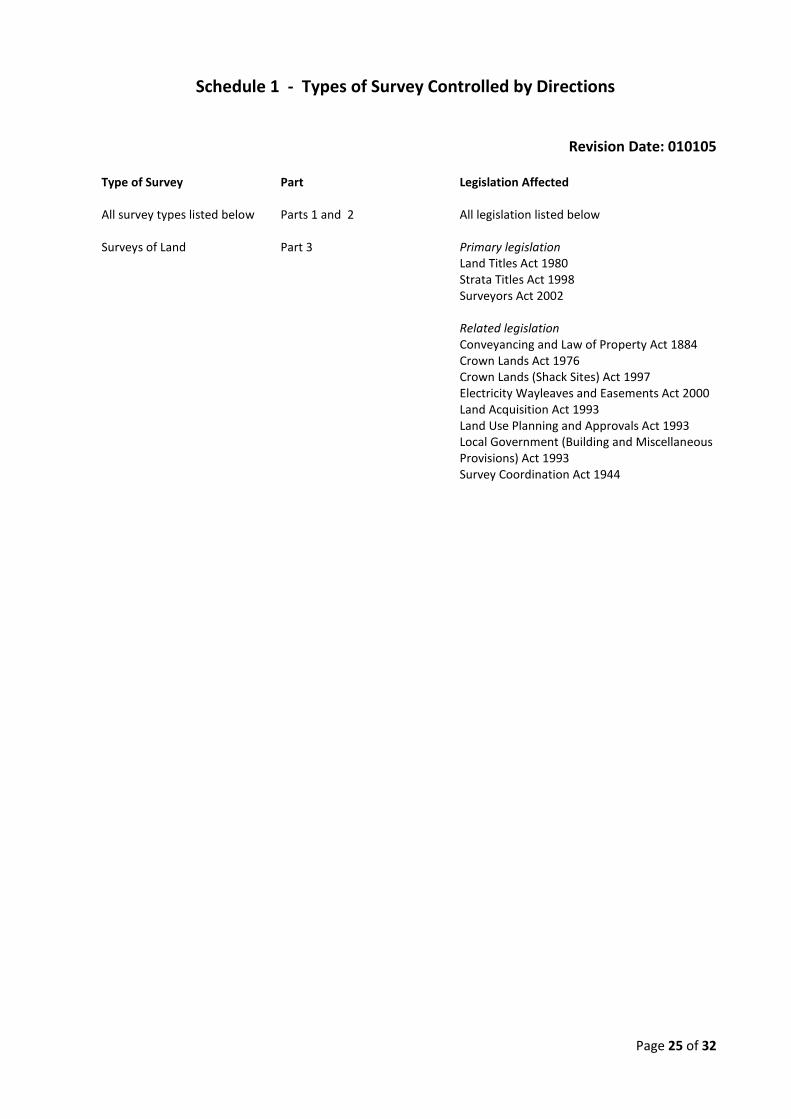
Schedule 1 - Types of Survey Controlled by Directions
Revision Date: 010105
Type of Survey Part Legislation Affected All survey types listed below Parts 1 and 2 All legislation listed below Surveys of Land Part 3 Primary legislation Land Titles Act 1980
Strata Titles Act 1998 Surveyors Act 2002 Related legislation
Conveyancing and Law of Property Act 1884 Crown Lands Act 1976
Crown Lands (Shack Sites) Act 1997 Electricity Wayleaves and Easements Act 2000
Land Acquisition Act 1993 Land Use Planning and Approvals Act 1993 Local Government (Building and Miscellaneous
Provisions) Act 1993 Survey Coordination Act 1944
Page 26 of 32
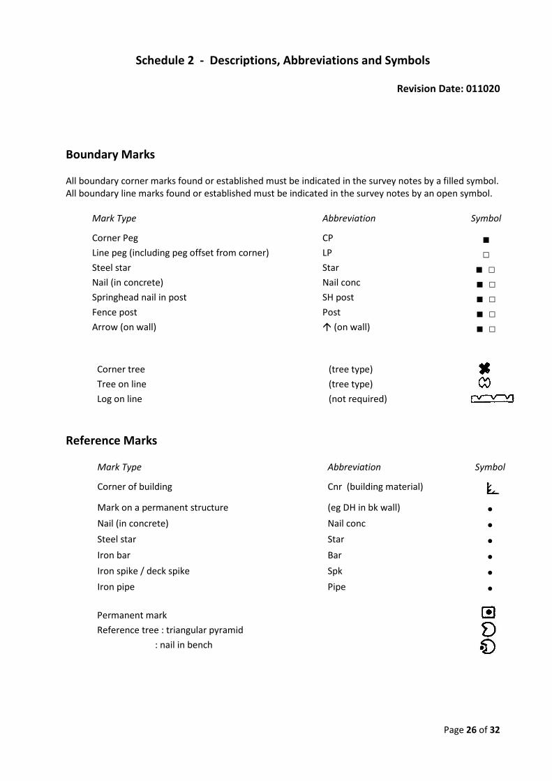
Schedule 2 - Descriptions, Abbreviations and Symbols
Revision Date: 011020
Boundary Marks All boundary corner marks found or established must be indicated in the survey notes by a filled symbol. All boundary line marks found or established must be indicated in the survey notes by an open symbol.
Mark Type Abbreviation Symbol
Corner Peg CP ■ Line peg (including peg offset from corner) LP □ Steel star Star ■ □ Nail (in concrete) Nail conc ■ □ Springhead nail in post SH post ■ □ Fence post Post ■ □ Arrow (on wall) (on wall) ■ □
Corner tree (tree type) Tree on line (tree type) Log on line (not required)
Reference Marks
Mark Type Abbreviation Symbol
Corner of building Cnr (building material)
Mark on a permanent structure (eg DH in bk wall) • Nail (in concrete) Nail conc • Steel star Star • Iron bar Bar • Iron spike / deck spike Spk • Iron pipe Pipe •
Permanent mark Reference tree : triangular pyramid : nail in bench
Page 27 of 32
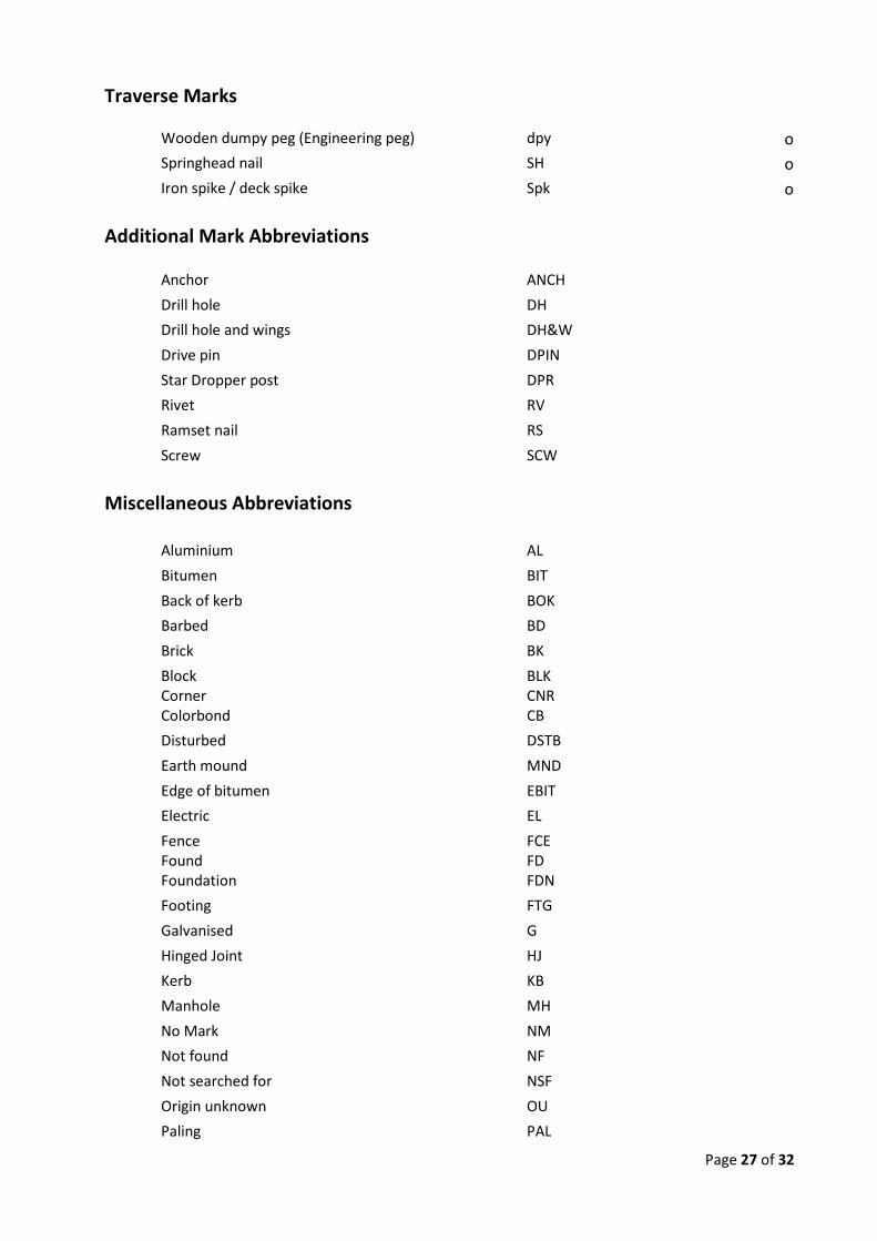
Traverse Marks
Wooden dumpy peg (Engineering peg) dpy o Springhead nail SH o Iron spike / deck spike Spk o
Additional Mark Abbreviations
Anchor ANCH Drill hole DH Drill hole and wings DH&W Drive pin DPIN Star Dropper post DPR Rivet RV Ramset nail RS Screw SCW
Miscellaneous Abbreviations
Aluminium AL Bitumen BIT Back of kerb BOK Barbed BD Brick BK Block Corner
BLK CNR
Colorbond CB Disturbed DSTB Earth mound MND Edge of bitumen EBIT Electric EL Fence Found
FCE FD
Foundation FDN Footing FTG Galvanised G Hinged Joint HJ Kerb KB Manhole MH No Mark NM Not found NF Not searched for NSF Origin unknown OU Paling PAL
Page 28 of 32
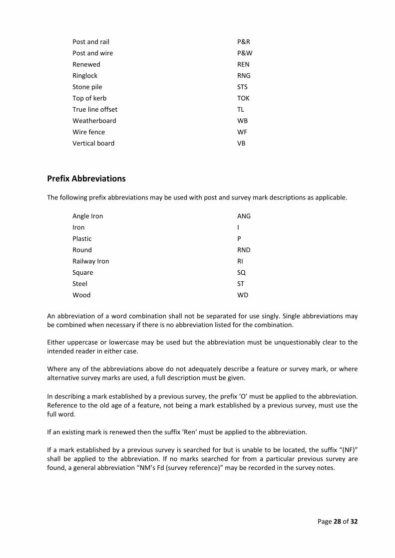
Post and rail P&R Post and wire P&W Renewed REN Ringlock RNG Stone pile STS Top of kerb TOK True line offset TL Weatherboard WB Wire fence WF Vertical board VB
Prefix Abbreviations The following prefix abbreviations may be used with post and survey mark descriptions as applicable.
Angle Iron ANG Iron I Plastic P Round RND Railway Iron RI Square SQ Steel ST Wood WD
An abbreviation of a word combination shall not be separated for use singly. Single abbreviations may be combined when necessary if there is no abbreviation listed for the combination. Either uppercase or lowercase may be used but the abbreviation must be unquestionably clear to the intended reader in either case. Where any of the abbreviations above do not adequately describe a feature or survey mark, or where alternative survey marks are used, a full description must be given. In describing a mark established by a previous survey, the prefix ‘O’ must be applied to the abbreviation. Reference to the old age of a feature, not being a mark established by a previous survey, must use the full word. If an existing mark is renewed then the suffix ‘Ren’ must be applied to the abbreviation. If a mark established by a previous survey is searched for but is unable to be located, the suffix “(NF)” shall be applied to the abbreviation. If no marks searched for from a particular previous survey are found, a general abbreviation “NM’s Fd (survey reference)” may be recorded in the survey notes.

Page 29 of 32
Symbols
Centre line Fence: off boundary Fence : on boundary
Page 30 of 32
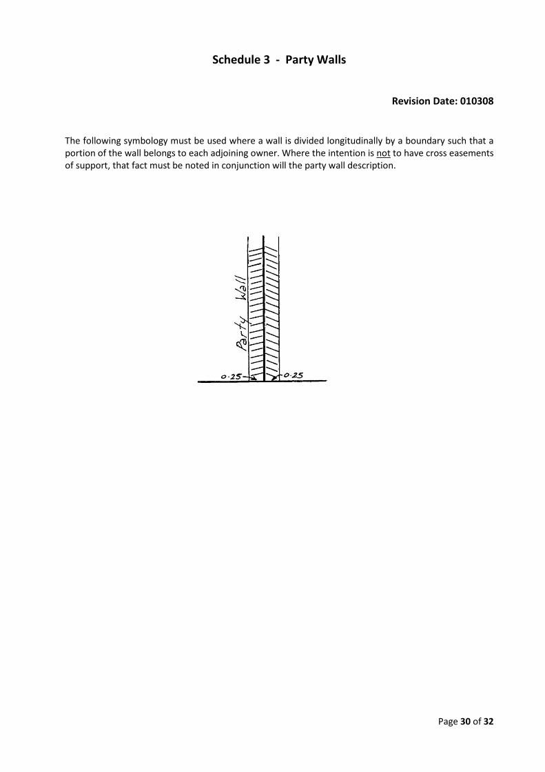
Schedule 3 - Party Walls
Revision Date: 010308
The following symbology must be used where a wall is divided longitudinally by a boundary such that a portion of the wall belongs to each adjoining owner. Where the intention is not to have cross easements of support, that fact must be noted in conjunction will the party wall description.
Page 31 of 32
Schedule 4 - Electricity Wayleave Identification Surveys ( Sample Plan )
Revision Date: 010105
Page 32 of 32
Schedule 5 - Form of of Survey Marks
Revision Date: 101214