Surveillance and Datalink Communication … and Datalink Communication Performance Analysis for ......
65
July 2012 NASA/CR–2012-217590 Surveillance and Datalink Communication Performance Analysis for Distributed Separation Assurance System Architectures William W. Chung, Dennis J. Linse, Omeed Alaverdi, Carlos Ifarraguerri, Scott C. Seifert, Dan Salvano, and Dale Calender Science Applications International Corporation, Hampton, Virginia https://ntrs.nasa.gov/search.jsp?R=20120013095 2018-05-31T15:42:38+00:00Z
Transcript of Surveillance and Datalink Communication … and Datalink Communication Performance Analysis for ......
July 2012
NASA/CR–2012-217590
Surveillance and Datalink Communication Performance Analysis for Distributed Separation Assurance System Architectures
William W. Chung, Dennis J. Linse, Omeed Alaverdi, Carlos Ifarraguerri, Scott C. Seifert, Dan Salvano, and Dale Calender Science Applications International Corporation, Hampton, Virginia
https://ntrs.nasa.gov/search.jsp?R=20120013095 2018-05-31T15:42:38+00:00Z

NASA STI Program . . . in Profile
Since its founding, NASA has been dedicated to the advancement of aeronautics and space science. The NASA scientific and technical information (STI) program plays a key part in helping NASA maintain this important role.
The NASA STI program operates under the auspices of the Agency Chief Information Officer. It collects, organizes, provides for archiving, and disseminates NASA’s STI. The NASA STI program provides access to the NASA Aeronautics and Space Database and its public interface, the NASA Technical Report Server, thus providing one of the largest collections of aeronautical and space science STI in the world. Results are published in both non-NASA channels and by NASA in the NASA STI Report Series, which includes the following report types:
TECHNICAL PUBLICATION. Reports of
completed research or a major significant phase of research that present the results of NASA Programs and include extensive data or theoretical analysis. Includes compilations of significant scientific and technical data and information deemed to be of continuing reference value. NASA counterpart of peer-reviewed formal professional papers, but having less stringent limitations on manuscript length and extent of graphic presentations.
TECHNICAL MEMORANDUM. Scientific
and technical findings that are preliminary or of specialized interest, e.g., quick release reports, working papers, and bibliographies that contain minimal annotation. Does not contain extensive analysis.
CONTRACTOR REPORT. Scientific and
technical findings by NASA-sponsored contractors and grantees.
CONFERENCE PUBLICATION.
Collected papers from scientific and technical conferences, symposia, seminars, or other meetings sponsored or co-sponsored by NASA.
SPECIAL PUBLICATION. Scientific,
technical, or historical information from NASA programs, projects, and missions, often concerned with subjects having substantial public interest.
TECHNICAL TRANSLATION.
English-language translations of foreign scientific and technical material pertinent to NASA’s mission.
Specialized services also include organizing and publishing research results, distributing specialized research announcements and feeds, providing information desk and personal search support, and enabling data exchange services. For more information about the NASA STI program, see the following: Access the NASA STI program home page
at http://www.sti.nasa.gov E-mail your question to [email protected] Fax your question to the NASA STI
Information Desk at 443-757-5803 Phone the NASA STI Information Desk at
443-757-5802 Write to:
STI Information Desk NASA Center for AeroSpace Information 7115 Standard Drive Hanover, MD 21076-1320
National Aeronautics and Space Administration Langley Research Center Prepared for Langley Research Center Hampton, Virginia 23681-2199 under Contract NNL11AA05C
July 2012
NASA/CR–2012-217590
Surveillance and Datalink Communication Performance Analysis for Distributed Separation Assurance System Architectures
William W. Chung, Dennis J. Linse, Omeed Alaverdi, Carlos Ifarraguerri, Scott C. Seifert, Dan Salvano, and Dale Calender Science Applications International Corporation, Hampton, Virginia
Available from:
NASA Center for AeroSpace Information 7115 Standard Drive
Hanover, MD 21076-1320 443-757-5802
Acknowledgment
This work was funded by a NASA National Research Announcement under the Concepts and Technology Development Project of the NASA Airspace Systems Program under Contract NNL11AA05C. The team wishes to thank Sally Johnson, David Wing, and Maria Consiglio of NASA Langley Research Center for their technical guidance and advice.
The use of trademarks or names of manufacturers in this report is for accurate reporting and does not constitute an official endorsement, either expressed or implied, of such products or manufacturers by the National Aeronautics and Space Administration.
1
Summary
This study investigates the effects of two technical enablers: Automatic Dependent Surveillance – Broadcast (ADS-B) and digital datalink communication, of the Federal Aviation Administration’s Next Generation Air Transportation System (NextGen) under two separation assurance (SA) system architectures: ground-based SA and airborne SA, on overall separation assurance performance. Datalink performance such as successful reception probability in both surveillance and communication messages, and surveillance accuracy are examined in various operational conditions. Required SA performance is evaluated as a function of subsystem performance, using availability, continuity, and integrity metrics to establish overall required separation assurance performance, under normal and off-nominal conditions.
2
Table of Contents
1 Introduction .......................................................................................................................................................... 9
2 NextGen SA System Architectures .................................................................................................................... 11
2.1 Current SA System Architectures ................................................................................................................. 11
2.2 NextGen Surveillance System Architectures ................................................................................................ 14
2.3 NextGen Communication System Architectures ........................................................................................... 15
2.4 NextGen Separation Assurance Concepts Of Operation ............................................................................... 16
3 Required Separation Assurance Performance .................................................................................................... 18
3.1 Proposed Approach ....................................................................................................................................... 18
3.2 Conflict Detection Zone ................................................................................................................................ 19
3.3 Maneuvering to Achieve Separation Assurance ............................................................................................ 21
4 Modeling of Distributed SA Datalink System Architectures ............................................................................. 23
4.1 Ground-Based SA Datalink System Architecture ......................................................................................... 23
4.2 Airborne SA Datalink System Architecture .................................................................................................. 32
4.3 Summary of Modeling References ................................................................................................................ 35
5 Test Design ........................................................................................................................................................ 37
5.1 Availability, Continutity, and Integrity ......................................................................................................... 37
5.2 Actual Separation Assurance Performance (ASAP) ...................................................................................... 37
5.3 Test Matrix .................................................................................................................................................... 37
6 Test Results and Performance Analysis ............................................................................................................. 40
6.1 Ground-Based Separation Assurance System Architecture ........................................................................... 41
6.2 Airborne Separation Assurance System Architecture ................................................................................... 47
6.3 Comparing Ground-Based and Airborne Results .......................................................................................... 55
7 Conclusions ........................................................................................................................................................ 57
8 Recommendations .............................................................................................................................................. 58
9 References .......................................................................................................................................................... 59
3
List of Tables
Table 2-1. Capabilities Planned for the Data Communication Program ........................................................ 16
Table 4-1. Comparison of FRUIT rate between the verification data and the model .................................... 25
Table 4-2. Surveillance uncertainty and accuracy ......................................................................................... 27
Table 4-3. Summary of surveillance modeling and performance references ................................................. 35
Table 4-4. Summary of communication and maneuver modeling and performance references .................... 36
Table 5-1. Test matrix for the required separation assurance performance study ......................................... 39
4
List of Figures
Figure 2-1. Current NAS SA system architecture ......................................................................................... 11
Figure 2-2. Current NAS terrestrial network system architecture ................................................................. 12
Figure 2-3. ADS-B ground-based surveillance system architecture .............................................................. 14
Figure 2-4. Subsystems from Aircraft Separation Assurance System ........................................................... 15
Figure 2-5. A representative VDL-2 datalink communication system architecture ....................................... 16
Figure 3-1. A current NAS separation assurance scenario ............................................................................ 18
Figure 3-2. Definition of CDZ according to DO-289 .................................................................................... 20
Figure 3-3. Assured Collision Avoidance Distance (ACAD) ........................................................................ 20
Figure 3-4. A Collision Detection Zone as a function of surveillance and communication performance ..... 21
Figure 3-5. Lateral maneuvering to maintain clear of separation volume ..................................................... 22
Figure 4-1. A representative ground-based surveillance system architecture ................................................ 23
Figure 4-2. A block diagram to determine the required surveillance time from 1090 MHz ADS-B ............. 24
Figure 4-3. A representative terrestrial latency in normal distribution .......................................................... 25
Figure 4-4. Verification of an ADS-B ground receiver model ...................................................................... 26
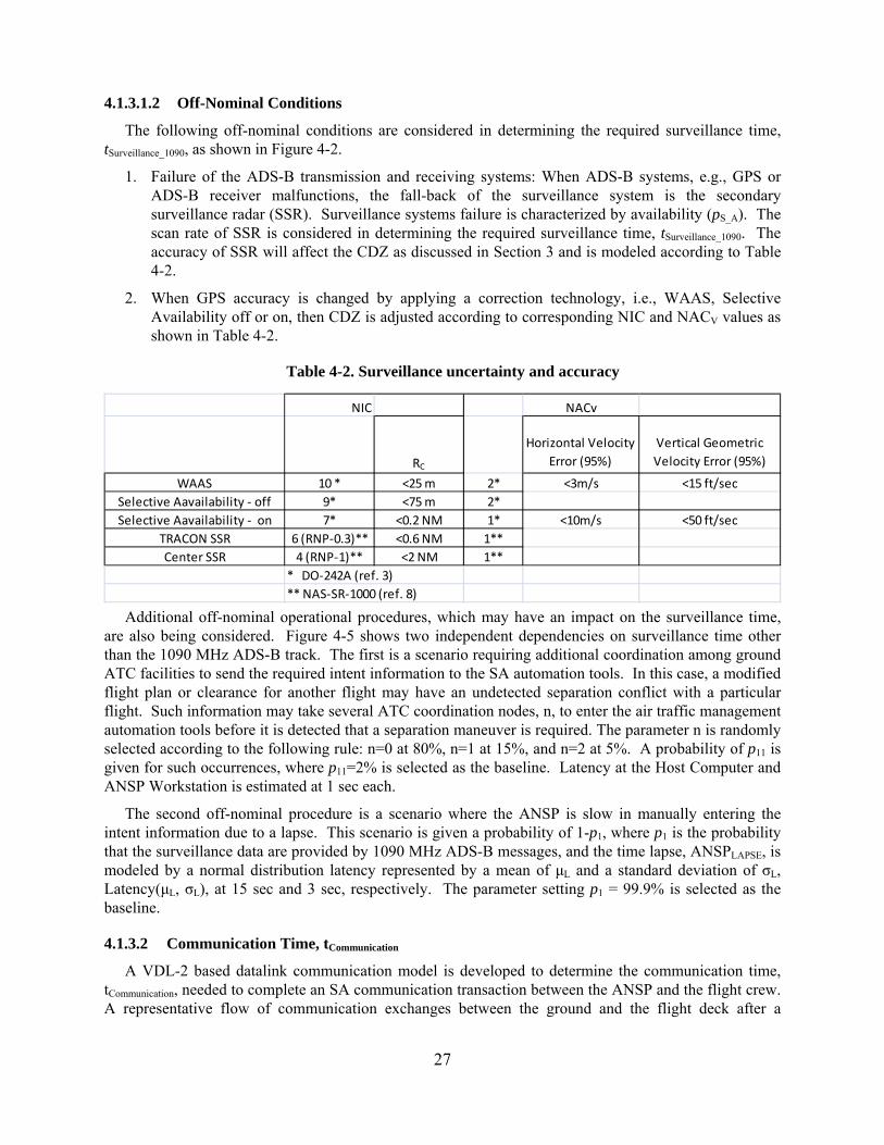
Figure 4-5. A block diagram to determine the required surveillance performance, tSurveillance ....................... 28
Figure 4-6. Components to determine the required communication performance, tCommunication .................... 28
Figure 4-7. A representative ANSP-review human response model in lognormal distribution ..................... 29
Figure 4-8. A block diagram to determine the required surveillance time from 1090 MHz ADS-B ............. 30
Figure 4-9. Required Separation Assurance Performance, tRSAP ................................................................... 32
Figure 4-10. A representative Airborne-Centric separation assurance system architecture .......................... 32
Figure 4-11. An intent-based Airborne-Centric concept required surveillance time, tSurveillance .................... 34
Figure 4-12. A block diagram to determine the required surveillance time .................................................. 34
Figure 6-1. Determination of the 95th percentile from 10,000 runs of ground-based baseline case, TC0, at 20 NM from the ADS-B radio station ........................................................................................................................ 40
Figure 6-2. Actual separation assurance performance due to traffic density ................................................. 42
Figure 6-3. Actual separation assurance performance due to surveillance uncertainty and accuracy ........... 43
Figure 6-4. Effects on ASAP due to communication message size and transmission rate ............................ 44
Figure 6-5. Effects on ASAP due to datalink and voice ................................................................................ 45
Figure 6-6. Effects on ASAP due to CDZ or separation minimum ............................................................... 46
Figure 6-7. Effects on ASAP due to traffic density with a vertical offset maneuver ..................................... 47
Figure 6-8. Traffic density effects on ASAP of the Airborne SA system architecture .................................. 48
Figure 6-9. Accuracy effects on ASAP of an airborne SA system architecture ............................................ 49
Figure 6-10. Number of intent messages effects on ASAP of an airborne .................................................... 50
Figure 6-11. Effects on ASAP due to CDZ ................................................................................................... 51
5
Figure 6-12. Effects on ASAP due to ownship’s speed ................................................................................. 52
Figure 6-13. Effects on ASAP due to source of intent messages ................................................................... 53
Figure 6-14. Effects on ASAP due to traffic density for a vertical offset maneuver ..................................... 54
Figure 6-15. Comparison of ASAP between ground-based and airborne baseline cases .............................. 55
Figure 6-16. Comparison between the ground-based and airborne concepts under high traffic density ....... 56
6
Nomenclature
4D – Four Dimensional
A/V – Air Vehicle
ACAD – Assured Collision Avoidance Distance
ACARS – Aircraft Communications Addressing and Reporting System
ACCC – Area Control Computer Complex
ACF – Area Control Facility
ADS-B – Automatic Dependent Surveillance - Broadcast
AGL – Above Ground Level
AMCCWS – ACF Maintenance Control Center Workstation
ANSP – Air Navigation Service Provider
APT - Airport
ARTCC – Air Route Traffic Control Center
ASAS – Airborne Separation Assurance System
ASAP – Actual Separation Assurance Performance
ATCSCC- Air Traffic Control System Command Center
ATCT – Air Traffic Control Tower
ATN – Aeronautical Telecommunications Network
ATOP – Advanced Technologies and Oceanic Procedure
CARTS – Common Automated Radar Terminal System
CD&R – Conflict Detection and Resolution
CDTI – Cockpit Display of Traffic Information
CDZ – Conflict Detection Zone
CERAP – Combined Center and Radar Approach Control
ConOps – Concept of Operations
CPA – Closest Point of Approach
DLP – Data Link Processor
DME – Distance Measuring Equipment
ERAM – En Route Automation Modernization
FIS-B – Flight Information Services - Broadcast
FL – Flight Level (in 100 ft increments)
FMC – Flight Management Computer
FMS – Flight Management System
FRUIT – (Unwanted) Friendly Replies Unsynchronized In Time (interference, background)
Ft - Feet
GMCC – General National Airspace System Maintenance Control Center
7
GMCCWS – General National Airspace System Maintenance Control Center Workstation
GPS – Global Position System
HF – High Frequency
HRM – Human Response Model
ILS – Instrument Landing System
L/W – Length and Width Dimension
MDT – Maintenance Data Terminal
MFD – Multi-Functional Display
MPLS – Multi-Protocol Label Switching
MPS – Maintenance Processor System
NACV – Navigation Accuracy Category for Velocity
NAS – National Airspace System
NIC – Navigation Integrity Categories
NOC – Network Operations Center
NM – Nautical Mile
pC_A – Availability of communication subsystems
pC_C – Continuity of VDL-2 message transmission and receiving
pC_FC – Successful VDL-2 reception probability due to collision
pS_I – Integrity of received VDL-2 datalink messages
pS_A – Availability of ADS-B subsystems
pS_C – Continuity of ADS-B message transmission and receiving
pS_FF – Successful ADS-B reception probability due to Free-Space Loss and FRUIT
pS_I – Integrity of received ADS-B messages
PSR – Primary Surveillance Radar
rC – VDL-2 message transmission rate
RF – Radio Frequency
RSAP – Required Separation Assurance Performance
RVSM – Reduced Vertical Separation Minima SA – Separation Assurance
SATCOM – Satellite Communications
SDP – Service Delivery Point
SSR – Secondary Surveillance Radar
STARS – Standard Terminal Automation Replacement System
SWIM – System Wide Information Management
T95 – The 95th Percentile Value of Collected Data Set
TBO – Trajectory-Based Operations
8
TC – Trajectory Change
TCAS – Traffic Alert and Collision Avoidance System
TCP – Trajectory Change Point
TIS-B - Traffic Information Services - Broadcast
TRACON – Terminal Radar Approach Control
UAT – Universal Access Transceiver
UHF – Ultra High Frequency
URET – User Request Evaluation Tool
VDL-2 – VHF Data Link, Mode 2
VHF – Very High Frequency
VOR – VHF Omni-directional Range
VPN – Virtual Private Network
9
1 Introduction
As the U.S. continues the National Airspace System (NAS) transition from a ground-fix surveillance system to a performance-based concept of operations to increase the capacity of the NAS and improvements in delays and environment, e.g., emissions and noise, the fundamental operational system architecture in separation assurance (SA) is also evolving based on two key technology enablers: Automatic Dependent Surveillance – Broadcast (ADS-B) and digital datalink communication. This transition as well as the two technology enablers support the Next Generation Air Transportation System (NextGen) visions developed by the Joint Program Development Office (JPDO)1 and Federal Aviation Administration (FAA).2
ADS-B, with Global Positioning System (GPS) derived aircraft state information and intent messages, will lead to improved surveillance accuracy and track delivery performance for both ground and airborne situation awareness. It is expected that the full potential of ADS-B’s surveillance capabilities will support visual acquisition, conflict avoidance and collision avoidance, separation assurance and sequencing, flight-path deconfliction planning, and simultaneous approaches in the future as specified in RTCA DO-242A as well as many surveillance performance requirements based on ADS-B.3 It is important to develop a framework to evaluate these surveillance capabilities in support of concepts of operation (ConOps) under different SA system architectures.
The NextGen plans also anticipate an increased demand for communication between controllers and pilots. This is partially due to the predicted increase in traffic, and partially due to the increased complexity of routes and instructions. To accommodate this need, data communications will first become an alternative to traditional voice communications, and eventually become the predominate form of communication.4 Based on the FAA’s current plan, Very-High-Frequency (VHF) Data Link, Mode 2 (VDL-2), will be the format for the Aeronautical Telecommunications Network (ATN) to support the Controller-Pilot Datalink Communication (CPDLC) as the ANSP communicates clearances, route changes, and advisories to the flight crew to maintain safe separation of NAS traffic. As a key part of this ConOps, many datalink communication system performance attributes, such as dependency on range, interference, message size, and message rate, will impact communication performance.
Separation assurance relies on knowing relevant information about ongoing traffic operations, which may include traffic state and intent information (provided by the surveillance function), and traffic management decisions, i.e., clearances, route changes, and advisories transmitted to the cockpit (provided by the communication function). Since these subsystem functions are distributed within the NAS infrastructure, effectiveness in getting accurate and timely surveillance information and communication messages directly impacts the success of the separation assurance function. Thus, the main objective of this study is to investigate the relationship between separation assurance performance and surveillance/communication subsystem performance under two SA system architectures, i.e., ground-based SA and airborne SA.5 Independent variables are ADS-B surveillance and datalink communication capabilities and their performance attributes, such as availability, continuity, and integrity. Availability is defined as the probability that the ADS-B or datalink transmitter and receiver are available for an operation. Continuity is the probability that the system successfully completes an operation, presuming that the system is available at the start of that operation. Integrity is the probability that there are no undetected errors in a completed data message transaction given that the ADS-B or datalink system is supplied with correct source data. Both SA system architectures in this study rely on distributed surveillance information and communication message exchange to provide the required separation assurance in assuring the safety of the flying public.
Subsystem performances identified in both SA system architectures, which include surveillance systems and communication systems, human response performance, and terrestrial network performance,
10
are characterized according to a physics-based modeling approach, past studies, and existing performance standards respectively. Additional system parameters, such as range of surveillance and communication, track density, and accuracy of the traffic track information are also evaluated. A Monte-Carlo simulation is developed to include these subsystem characteristics following the SA system architectures such that various operational conditions and parameters can be evaluated to investigate the resulting separation assurance performance.
11
2 NextGen SA System Architectures
NextGen is a broad term for the set of goals, programs, systems, decisions, and new technology capabilities that will modernize the NAS. This modernization plan is laid out in phases, and culminates in a final architecture in 2025. It incorporates many high-level concepts that have been under development, all with the goal of increasing safety, capacity, and efficiency. The ultimate goal of NextGen is to maintain safe operations of the NAS with increased demand of air transportation services.
This highlights the requirements of separation assurance, which provides safe separation among airborne traffic as well as aircraft ground traffic through the NAS systems. These systems include surveillance, communication, and terrestrial network systems; NAS participants, which include ANSP, flight crews, and other stakeholders; and integrated processes to separate the traffic at a safe minimum distance. Before examining required separation assurance performance according to NextGen’s surveillance and communication capabilities, i.e., ADS-B and datalink communication respectively, it is important to develop an understanding of the current NAS SA system architectures and SA ConOps based on existing surveillance and communication capabilities, since many of the performance attributes will be carried over into the NextGen SA system architectures.
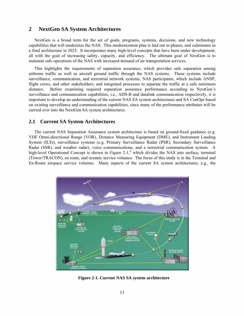
2.1 Current SA System Architectures
The current NAS Separation Assurance system architecture is based on ground-fixed guidance (e.g. VHF Omni-directional Range (VOR), Distance Measuring Equipment (DME), and Instrument Landing System (ILS)), surveillance systems (e.g. Primary Surveillance Radar (PSR), Secondary Surveillance Radar (SSR), and weather radar), voice communications, and a terrestrial communication system. A high-level Operational Concept is shown in Figure 2-1,6 which divides the NAS into surface, terminal (Tower/TRACON), en route, and oceanic service volumes. The focus of this study is in the Terminal and En-Route airspace service volumes. Many aspects of the current SA system architectures, e.g., the
Figure 2-1. Current NAS SA system architecture
12
communication network, remain relevant under the NextGen SA system architectures.
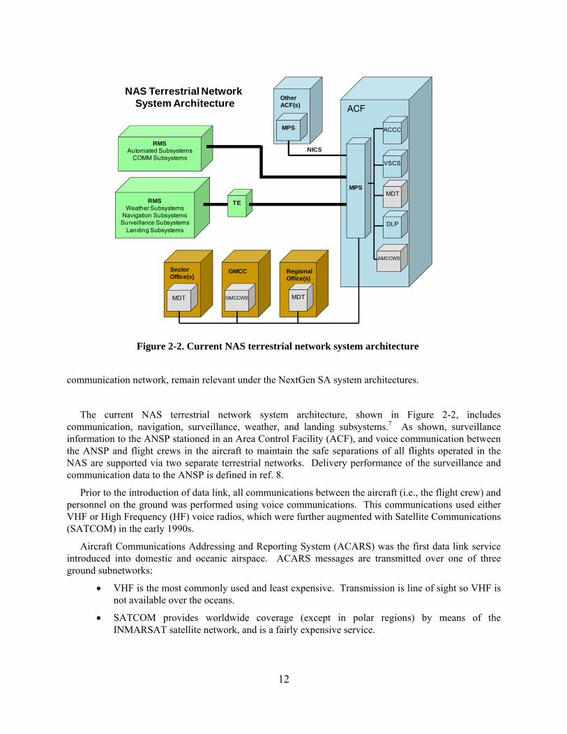
The current NAS terrestrial network system architecture, shown in Figure 2-2, includes communication, navigation, surveillance, weather, and landing subsystems.7 As shown, surveillance information to the ANSP stationed in an Area Control Facility (ACF), and voice communication between the ANSP and flight crews in the aircraft to maintain the safe separations of all flights operated in the NAS are supported via two separate terrestrial networks. Delivery performance of the surveillance and communication data to the ANSP is defined in ref. 8.
Prior to the introduction of data link, all communications between the aircraft (i.e., the flight crew) and personnel on the ground was performed using voice communications. This communications used either VHF or High Frequency (HF) voice radios, which were further augmented with Satellite Communications (SATCOM) in the early 1990s.
Aircraft Communications Addressing and Reporting System (ACARS) was the first data link service introduced into domestic and oceanic airspace. ACARS messages are transmitted over one of three ground subnetworks:
VHF is the most commonly used and least expensive. Transmission is line of sight so VHF is not available over the oceans.
SATCOM provides worldwide coverage (except in polar regions) by means of the INMARSAT satellite network, and is a fairly expensive service.
ACF
MPSMDT
VSCS
DLP
ACCC
MDT
RegionalOffice(s)
GMCCWS
GMCC
RMSAutomated Subsystems
COMM Subsystems
RMSWeather Subsystems
Navigation SubsystemsSurveillance Subsystems
Landing Subsystems
TE
MDT
SectorOffice(s)
OtherACF(s)
MPS
NICS
AMCCWS
NAS Terrestrial Network System Architecture
Figure 2-2. Current NAS terrestrial network system architecture
13
HF is the most recently established sub-network. Its purpose is to provide coverage in the polar regions where SATCOM coverage is unreliable.
Under the current NAS SA ConOps, the ANSP has the sole responsibility of separation assurance. Surveillance and communication infrastructures have been developed based on this ConOps as well as rules and procedures such that the ANSP can manage separation throughout the airspace.
2.1.1 Separation Assurance Concept of Operations in Terminal and En Route Airspace
Terminal Airspace
In the terminal airspace, it is the ANSP’s responsibility to provide aircraft separation and expedite the flow of traffic between airports and the en route environment. In order to complete this task, ANSPs are provided with automation and communication systems. The automation systems (Common ARTS and STARS) deliver a situational display of the airspace with tracks and flight data. The communication system gives the controller a constant voice link to the flight crew to issue commands or request information.
The terminal automation system (STARS or CARTS) provides the controller with tactical conflict alerts for predicted encounters and imminent conflicts in support of 3 NM horizontal separation and 1000 ft vertical separation. The primary input for this process is short range radar, such as the ASR-9 and ASR-11. The radars have a PSR and SSR system. The secondary radar includes the Air Traffic Control Radar Beacon System (ATCRBS).9 The beacon system interrogates the aircraft every 4-6 seconds and provides the positional update to the terminal automation system. The terminal automation displays the tracks derived from the radar data. These tracks are correlated with flight plans from the Flight Data Input Output (FDIO) system. Each correlated target has a data block that displays basic flight ID information, altitude and ground speed. The display systems are called the Terminal Display Workstation (TDW) for the STARS and the ARTS Color Display (ACD) for the CARTS. The terminal automation system will display visual conflict alerts with 40 seconds warning for predicted conflicts and 30 seconds warning for imminent loss of separation.8
At present some terminal automation systems have been modified to process ADS-B data, which is much more accurate than radar. The use of ADS-B positional data combined with radar and multi-lateration systems promises a much more accurate separation assurance system for the future.
The next layer of automation for SA occurs between aircraft equipped with the Traffic Alert and Collision Avoidance System (TCAS). The TCAS will give pilots a traffic advisory (TA), i.e., when an aircraft has entered, or is projected to enter, the protected volume around the own aircraft, or a resolution advisory (RA), i.e., when a vertical maneuver should be performed to attain or maintain safe separation from a threat.
En Route Airspace
In the en route airspace, separation assurance remains the ANSP’s responsibility to maintain 5 NM horizontal and 1000 ft vertical separation. Traffic surveillance is provided through a network of primary and secondary surveillance radars. Separation assurance is performed in a three tiered fashion. The first tier is Conflict Probe,10 which is performed with the User Request Evaluation Tool (URET) system connected to the Host or the equivalent functionality of Conflict Probe in En Route Automation Modernization (ERAM) system. Conflict Probe performs with a 20 minute look-ahead horizon on intended trajectories developed from flight plans, alerting on aircraft pairs that could potentially have an encounter.
14
The second tier is tactical conflict alerting performed by the ATC automation system, i.e., Host or En Route Automation Modernization (ERAM), over a three minute horizon on radar tracks projected in the future on aircraft pairs predicted to have a potential encounter. ADS-B is being added as a new surveillance input, which promises greater accuracy for SA algorithms.
The third tier is performed by the TCAS system onboard aircraft that detects a proximity conflict with another aircraft.
2.2 NextGen Surveillance System Architectures
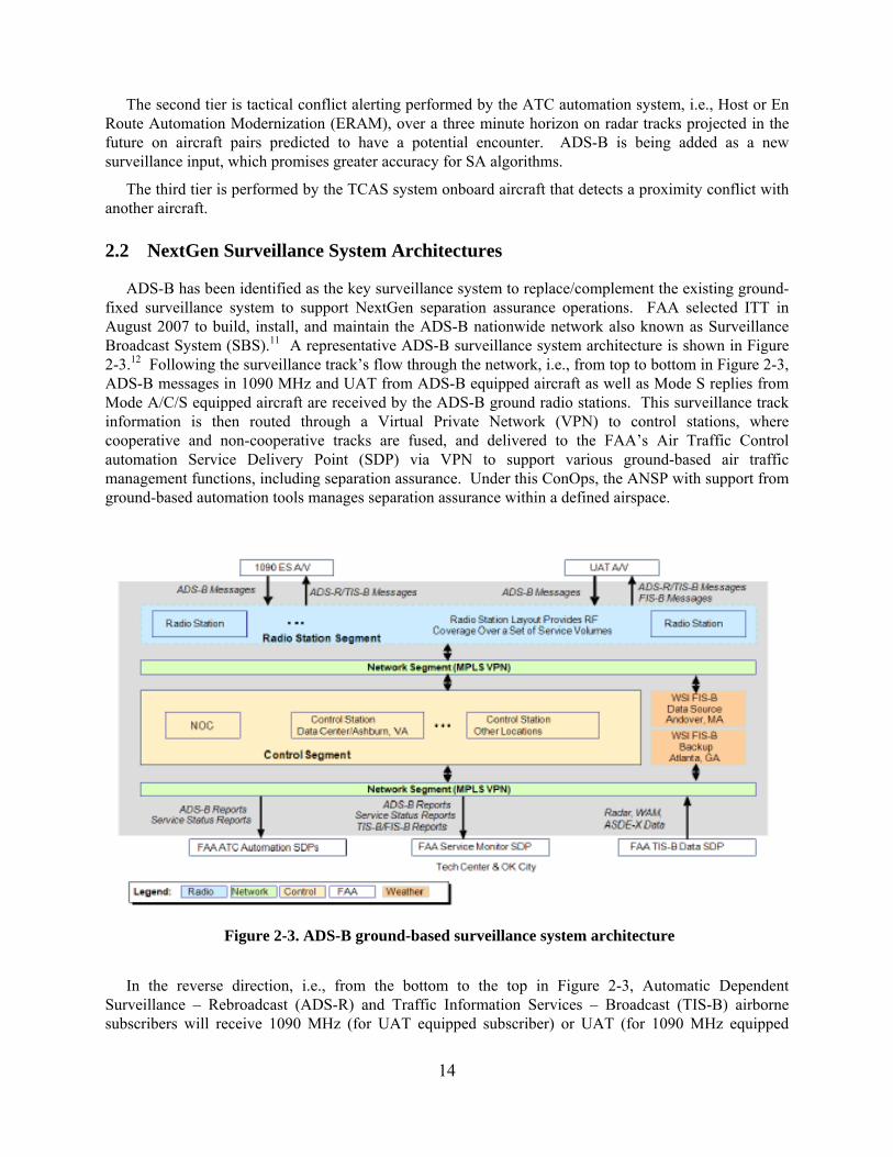
ADS-B has been identified as the key surveillance system to replace/complement the existing ground-fixed surveillance system to support NextGen separation assurance operations. FAA selected ITT in August 2007 to build, install, and maintain the ADS-B nationwide network also known as Surveillance Broadcast System (SBS).11 A representative ADS-B surveillance system architecture is shown in Figure 2-3.12 Following the surveillance track’s flow through the network, i.e., from top to bottom in Figure 2-3, ADS-B messages in 1090 MHz and UAT from ADS-B equipped aircraft as well as Mode S replies from Mode A/C/S equipped aircraft are received by the ADS-B ground radio stations. This surveillance track information is then routed through a Virtual Private Network (VPN) to control stations, where cooperative and non-cooperative tracks are fused, and delivered to the FAA’s Air Traffic Control automation Service Delivery Point (SDP) via VPN to support various ground-based air traffic management functions, including separation assurance. Under this ConOps, the ANSP with support from ground-based automation tools manages separation assurance within a defined airspace.
In the reverse direction, i.e., from the bottom to the top in Figure 2-3, Automatic Dependent Surveillance – Rebroadcast (ADS-R) and Traffic Information Services – Broadcast (TIS-B) airborne subscribers will receive 1090 MHz (for UAT equipped subscriber) or UAT (for 1090 MHz equipped
Figure 2-3. ADS-B ground-based surveillance system architecture
15
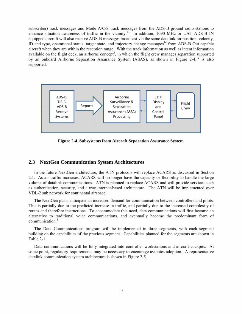
subscriber) track messages and Mode A/C/S track messages from the ADS-B ground radio stations to enhance situation awareness of traffic in the vicinity.13 In addition, 1090 MHz or UAT ADS-B IN equipped aircraft will also receive ADS-B messages broadcast via the same datalink for position, velocity, ID and type, operational status, target state, and trajectory change messages14 from ADS-B Out capable aircraft when they are within the reception range. With the track information as well as intent information available on the flight deck, an airborne concept5, in which the flight crew manages separation supported by an onboard Airborne Separation Assurance System (ASAS), as shown in Figure 2-4,12 is also supported.
2.3 NextGen Communication System Architectures
In the future NextGen architecture, the ATN protocols will replace ACARS as discussed in Section 2.1. As air traffic increases, ACARS will no longer have the capacity or flexibility to handle the large volume of datalink communications. ATN is planned to replace ACARS and will provide services such as authentication, security, and a true internet-based architecture. The ATN will be implemented over VDL-2 sub network for continental airspace.
The NextGen plans anticipate an increased demand for communication between controllers and pilots. This is partially due to the predicted increase in traffic, and partially due to the increased complexity of routes and therefore instructions. To accommodate this need, data communications will first become an alternative to traditional voice communications, and eventually become the predominant form of communication.4
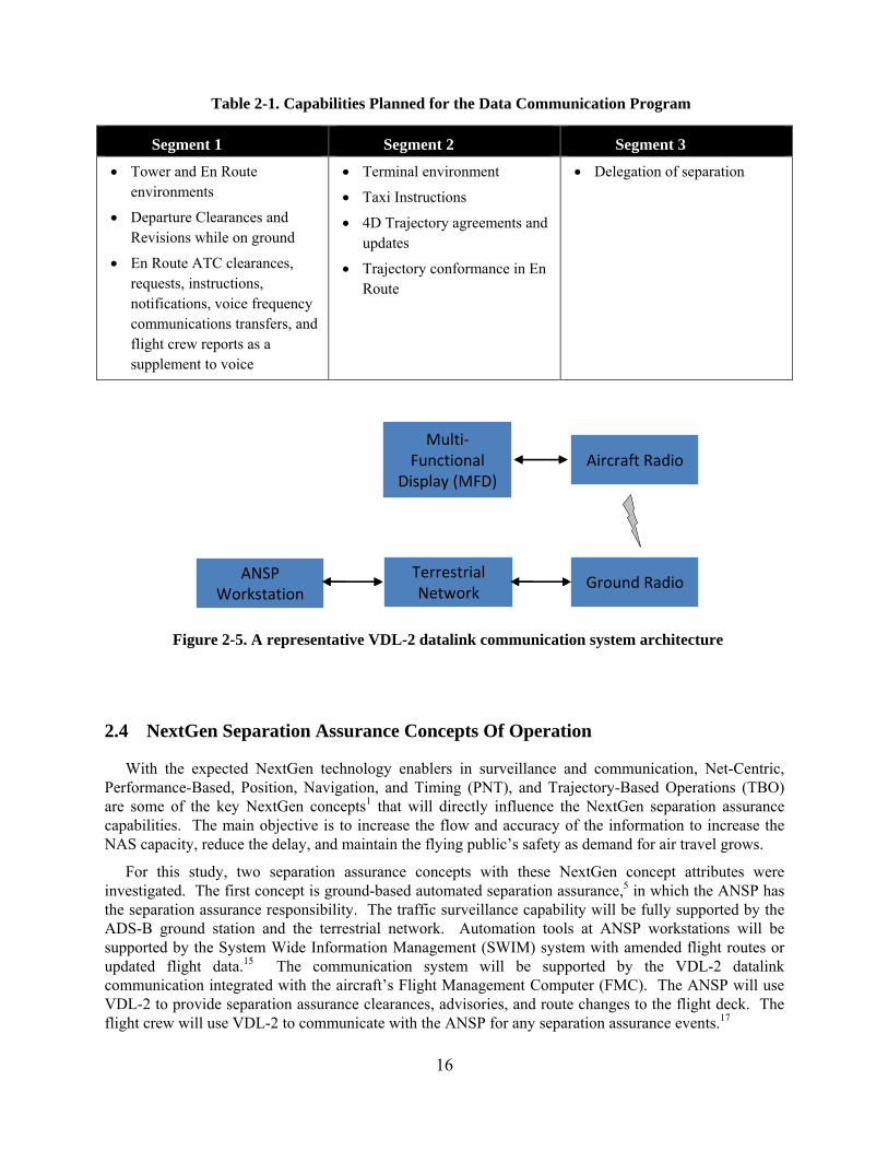
The Data Communications program will be implemented in three segments, with each segment building on the capabilities of the previous segment. Capabilities planned for the segments are shown in Table 2-1.
Data communications will be fully integrated into controller workstations and aircraft cockpits. At some point, regulatory requirements may be necessary to encourage avionics adoption. A representative datalink communication system architecture is shown in Figure 2-5.
ADS‐B,TIS‐B,ADS‐R
ReceiveSystems
Reports
AirborneSurveillance &Separation
Assurance (ASSA)Processing
CDTIDisplayand
ControlPanel
Flight Crew
Figure 2-4. Subsystems from Aircraft Separation Assurance System
16
Table 2-1. Capabilities Planned for the Data Communication Program
Segment 1 Segment 2 Segment 3
Tower and En Route environments
Departure Clearances and Revisions while on ground
En Route ATC clearances, requests, instructions, notifications, voice frequency communications transfers, and flight crew reports as a supplement to voice
Terminal environment
Taxi Instructions
4D Trajectory agreements and updates
Trajectory conformance in En Route
Delegation of separation
2.4 NextGen Separation Assurance Concepts Of Operation
With the expected NextGen technology enablers in surveillance and communication, Net-Centric, Performance-Based, Position, Navigation, and Timing (PNT), and Trajectory-Based Operations (TBO) are some of the key NextGen concepts1 that will directly influence the NextGen separation assurance capabilities. The main objective is to increase the flow and accuracy of the information to increase the NAS capacity, reduce the delay, and maintain the flying public’s safety as demand for air travel grows.
For this study, two separation assurance concepts with these NextGen concept attributes were investigated. The first concept is ground-based automated separation assurance,5 in which the ANSP has the separation assurance responsibility. The traffic surveillance capability will be fully supported by the ADS-B ground station and the terrestrial network. Automation tools at ANSP workstations will be supported by the System Wide Information Management (SWIM) system with amended flight routes or updated flight data.15 The communication system will be supported by the VDL-2 datalink communication integrated with the aircraft’s Flight Management Computer (FMC). The ANSP will use VDL-2 to provide separation assurance clearances, advisories, and route changes to the flight deck. The flight crew will use VDL-2 to communicate with the ANSP for any separation assurance events.17
Ground Radio
Aircraft Radio
Terrestrial Network
ANSP Workstation
Multi‐Functional
Display (MFD)
Ground Radio
Aircraft Radio
Terrestrial Network
ANSP Workstation
Multi‐Functional
Display (MFD)
Figure 2-5. A representative VDL-2 datalink communication system architecture
17
The second concept is the Autonomous Flight Rule (AFR) concept,5 in which the pilot manages the separation via the ASAS onboard automation. All cooperative traffic track information will be supported by ADS-B IN including the intent information from the airborne ADS-B messages as well ground re-transmitted track messages via TIS-B and/or ADS-R.17 The intent information could also come from the ground system via System Wide Information Management (SWIM).2 ASAS will provide the conflict detection and resolution functions, and recommended maneuver or route changes are provided to the flight crew to maintain separation. Under this concept, no additional communication will be required between the flight crew and the ANSP, although the voice communication frequency is available for additional coordination, if needed.
.
18
3 Required Separation Assurance Performance
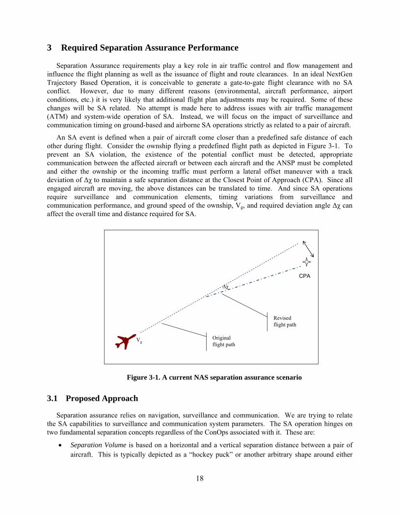
Separation Assurance requirements play a key role in air traffic control and flow management and influence the flight planning as well as the issuance of flight and route clearances. In an ideal NextGen Trajectory Based Operation, it is conceivable to generate a gate-to-gate flight clearance with no SA conflict. However, due to many different reasons (environmental, aircraft performance, airport conditions, etc.) it is very likely that additional flight plan adjustments may be required. Some of these changes will be SA related. No attempt is made here to address issues with air traffic management (ATM) and system-wide operation of SA. Instead, we will focus on the impact of surveillance and communication timing on ground-based and airborne SA operations strictly as related to a pair of aircraft.
An SA event is defined when a pair of aircraft come closer than a predefined safe distance of each other during flight. Consider the ownship flying a predefined flight path as depicted in Figure 3-1. To prevent an SA violation, the existence of the potential conflict must be detected, appropriate communication between the affected aircraft or between each aircraft and the ANSP must be completed and either the ownship or the incoming traffic must perform a lateral offset maneuver with a track deviation of Δχ to maintain a safe separation distance at the Closest Point of Approach (CPA). Since all engaged aircraft are moving, the above distances can be translated to time. And since SA operations require surveillance and communication elements, timing variations from surveillance and communication performance, and ground speed of the ownship, Vg, and required deviation angle Δχ can affect the overall time and distance required for SA.
3.1 Proposed Approach
Separation assurance relies on navigation, surveillance and communication. We are trying to relate the SA capabilities to surveillance and communication system parameters. The SA operation hinges on two fundamental separation concepts regardless of the ConOps associated with it. These are:
Separation Volume is based on a horizontal and a vertical separation distance between a pair of aircraft. This is typically depicted as a “hockey puck” or another arbitrary shape around either
VgOriginal flight path
Revised flight path
CPA
Figure 3-1. A current NAS separation assurance scenario
19
aircraft and defines the necessary protected airspace. The size of the Separation Volume is primarily based on the aircraft physical and flight characteristics, navigation performance, and surveillance capabilities. In addition, uncertainties associated with short term intent are addressed by adjusting the size of the separation volume. In this study, we assume a hockey puck shaped separation volume with a radius which will be defined as the Conflict Detection Zone (CDZ), and a vertical dimension of 1000 ft. above or below. It should be noted that this hockey puck is specifically defined for a given pair of aircraft and is placed about either the ownship or the engaged traffic.
Separation Threshold is the minimum required distance or time needed to detect, verify, and maneuver the aircraft in order to maintain clear of the required separation volume. Separation threshold is primarily a function of surveillance capability, i.e., time required to identify and establish a track with a potential conflict, and communication capabilities, i.e., time to communicate with the ANSP for a separation assurance maneuver to maintain safe separation. Navigation system capability is also a major contributor, particularly when ADS-B surveillance is used. Knowledge of intent can play a significant role in separation threshold for NextGen operations.
The current standard for separation volume is based on legacy VOR navigation accuracies along with ATC surveillance radar precision. In the absence of radar coverage, mandatory position reports are used to ensure SA.
The intent of this analysis is to relate the surveillance, communication, and possibly navigation subsystem performance parameters to the separation volume and separation threshold distance or time. Such information can then be used to define or refine the subsystem performance requirements to achieve a desired level of SA performance. However, both separation volume and threshold are strongly dependent on the ConOps associated with the air traffic management, air traffic control, and SA operations. The focus of the discussion below is on the separation threshold distance or time for SA. This way, the calculations are applicable to the current separation standards as well as future operations.
3.2 Conflict Detection Zone
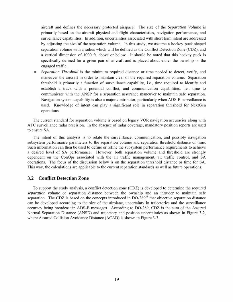
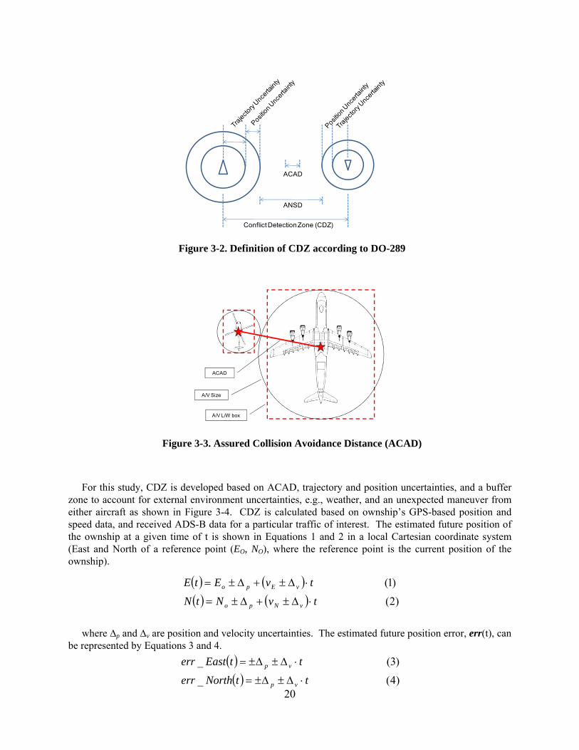
To support the study analysis, a conflict detection zone (CDZ) is developed to determine the required separation volume or separation distance between the ownship and an intruder to maintain safe separation. The CDZ is based on the concepts introduced in DO-28918 that objective separation distance can be developed according to the size of the airplane, uncertainty in trajectories and the surveillance accuracy being broadcast in ADS-B messages. According to DO-289, CDZ is the sum of the Assured Normal Separation Distance (ANSD) and trajectory and position uncertainties as shown in Figure 3-2, where Assured Collision Avoidance Distance (ACAD) is shown in Figure 3-3.
20
For this study, CDZ is developed based on ACAD, trajectory and position uncertainties, and a buffer zone to account for external environment uncertainties, e.g., weather, and an unexpected maneuver from either aircraft as shown in Figure 3-4. CDZ is calculated based on ownship’s GPS-based position and speed data, and received ADS-B data for a particular traffic of interest. The estimated future position of the ownship at a given time of t is shown in Equations 1 and 2 in a local Cartesian coordinate system (East and North of a reference point (EO, NO), where the reference point is the current position of the ownship).
where ∆p and ∆v are position and velocity uncertainties. The estimated future position error, err(t), can be represented by Equations 3 and 4.
ACAD
ANSD
Conflict Detection Zone (CDZ)
Figure 3-2. Definition of CDZ according to DO-289
ACAD
A/V L/W box
A/V Size
Figure 3-3. Assured Collision Avoidance Distance (ACAD)
)4(_
)3(_
ttNortherr
ttEasterr
vp
vp
)2(
)1(
tvNtN
tvEtE
vNpo
vEpo
21
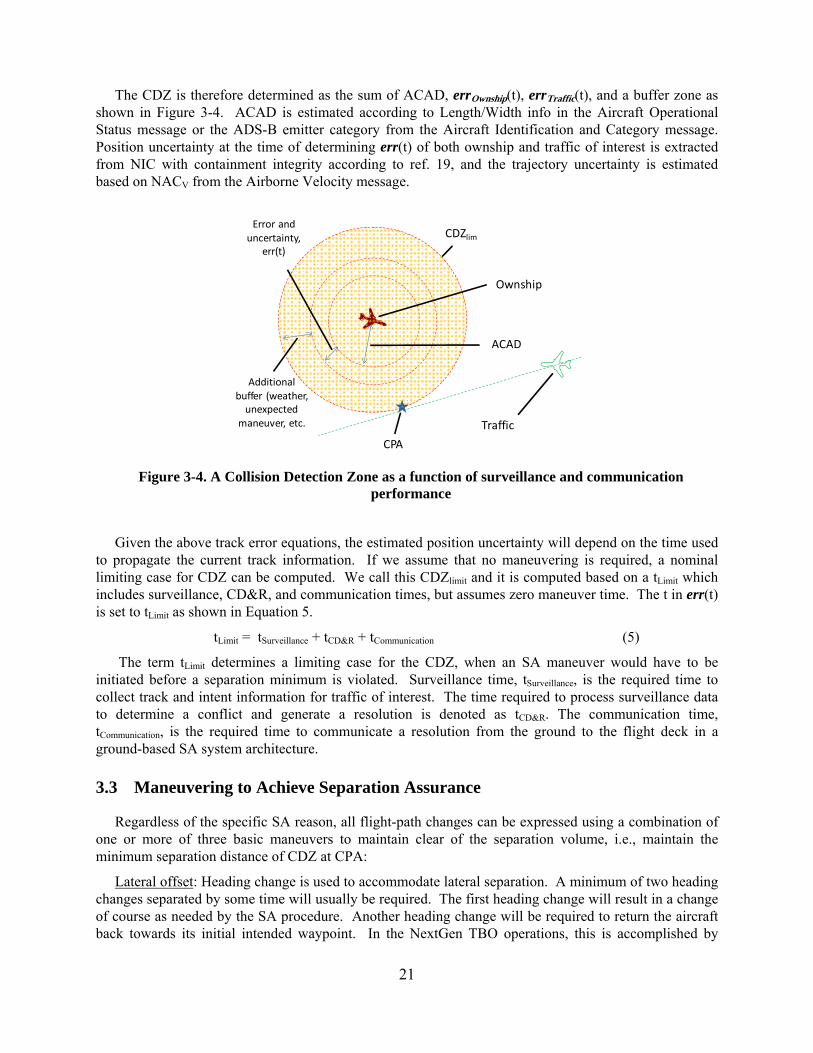
The CDZ is therefore determined as the sum of ACAD, errOwnship(t), errTraffic(t), and a buffer zone as shown in Figure 3-4. ACAD is estimated according to Length/Width info in the Aircraft Operational Status message or the ADS-B emitter category from the Aircraft Identification and Category message. Position uncertainty at the time of determining err(t) of both ownship and traffic of interest is extracted from NIC with containment integrity according to ref. 19, and the trajectory uncertainty is estimated based on NACV from the Airborne Velocity message.
Given the above track error equations, the estimated position uncertainty will depend on the time used to propagate the current track information. If we assume that no maneuvering is required, a nominal limiting case for CDZ can be computed. We call this CDZlimit and it is computed based on a tLimit which includes surveillance, CD&R, and communication times, but assumes zero maneuver time. The t in err(t) is set to tLimit as shown in Equation 5.
tLimit = tSurveillance + tCD&R + tCommunication (5)
The term tLimit determines a limiting case for the CDZ, when an SA maneuver would have to be initiated before a separation minimum is violated. Surveillance time, tSurveillance, is the required time to collect track and intent information for traffic of interest. The time required to process surveillance data to determine a conflict and generate a resolution is denoted as tCD&R. The communication time, tCommunication, is the required time to communicate a resolution from the ground to the flight deck in a ground-based SA system architecture.
3.3 Maneuvering to Achieve Separation Assurance
Regardless of the specific SA reason, all flight-path changes can be expressed using a combination of one or more of three basic maneuvers to maintain clear of the separation volume, i.e., maintain the minimum separation distance of CDZ at CPA:
Lateral offset: Heading change is used to accommodate lateral separation. A minimum of two heading changes separated by some time will usually be required. The first heading change will result in a change of course as needed by the SA procedure. Another heading change will be required to return the aircraft back towards its initial intended waypoint. In the NextGen TBO operations, this is accomplished by
CDZlim
Ownship
CPA
Traffic
ACAD
Error and uncertainty,
err(t)
Additional buffer (weather, unexpected
maneuver, etc.
Figure 3-4. A Collision Detection Zone as a function of surveillance and communication performance
22
introducing an interim trajectory change point (TCP) on the current route. Procedures involving parallel tracks will require more than two heading changes.
Vertical offset: Change in vertical flight path angle is used to facilitate vertical separation. Often the SA procedure requires an altitude change to accommodate crossing traffic. An altitude change maneuver will require two adjustments to the vertical flight path. The first change will initiate a specified rate of climb or descent. The second will capture the target altitude.
Speed change: Change in airspeed or Mach number is used to accommodate spacing or time of arrival. Multiple power adjustments are used to accelerate/decelerate and then maintain the desired airspeed. However, during certain high speed or low speed operations, further change of speed in a given direction may not be possible due to aircraft limitations. Also, speed changes during continuous descent operations will be more problematic and will require more detailed planning.
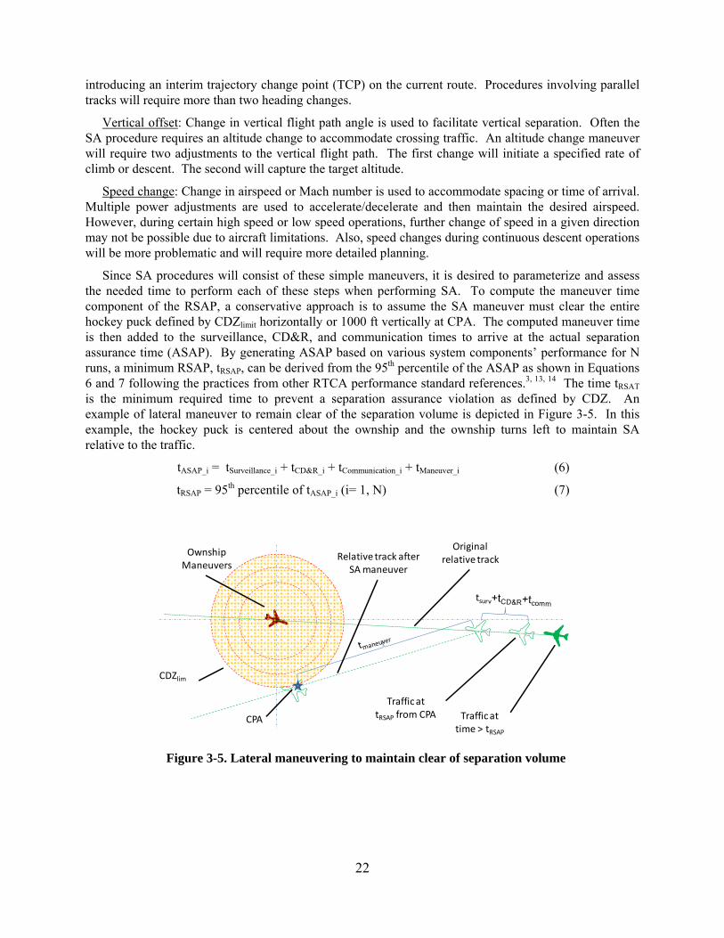
Since SA procedures will consist of these simple maneuvers, it is desired to parameterize and assess the needed time to perform each of these steps when performing SA. To compute the maneuver time component of the RSAP, a conservative approach is to assume the SA maneuver must clear the entire hockey puck defined by CDZlimit horizontally or 1000 ft vertically at CPA. The computed maneuver time is then added to the surveillance, CD&R, and communication times to arrive at the actual separation assurance time (ASAP). By generating ASAP based on various system components’ performance for N runs, a minimum RSAP, tRSAP, can be derived from the 95th percentile of the ASAP as shown in Equations 6 and 7 following the practices from other RTCA performance standard references.3, 13, 14 The time tRSAT is the minimum required time to prevent a separation assurance violation as defined by CDZ. An example of lateral maneuver to remain clear of the separation volume is depicted in Figure 3-5. In this example, the hockey puck is centered about the ownship and the ownship turns left to maintain SA relative to the traffic.
tASAP_i = tSurveillance_i + tCD&R_i + tCommunication_i + tManeuver_i (6)
tRSAP = 95th percentile of tASAP_i (i= 1, N) (7)
CDZlim
Traffic at tRSAP from CPA
Ownship Maneuvers
Traffic at time > tRSAP
Original relative track
CPA
Relative track after SA maneuver
Figure 3-5. Lateral maneuvering to maintain clear of separation volume
23
4 Modeling of Distributed SA Datalink System Architectures
To study the required separation assurance performance or RSAP, a Monte Carlo simulation is developed according to three key components in the separation assurance concept, i.e., surveillance, communication, and flight maneuvers as discussed in Section 3, to determine the actual separation assurance performance (ASAP) based on a set of performance parameters and nominal and off-nominal conditions, which are discussed in Section 5. The minimum RSAP can then be derived from the 95th percentile from ASAP data.
The performance of surveillance, communication, and flight maneuver are modeled according to two SA system architectures, i.e., ground-based and airborne concepts.5 Frame works of the modeling approach, which is developed based on datalink performance attributes of availability, continuity, and integrity, and datalink system performance parameters, are presented in the following sub-sections such that ASAP and associated surveillance performance and communication performance can be studied according to physics-based performance, specification-based performance, and performance results from past studies.
4.1 Ground-Based SA Datalink System Architecture
The ground-based SA system architecture is defined such that so the ANSP has the traffic information, including track and intent, automation tools to identify and resolve conflicts, as well as communication means to communicate with the flight crew to maintain safe separation according to separation standards of all flying aircraft in the designated airspace. The system architecture includes both surveillance and communication datalink subsystems.
4.1.1 Ground-Based SA Concept of Operations
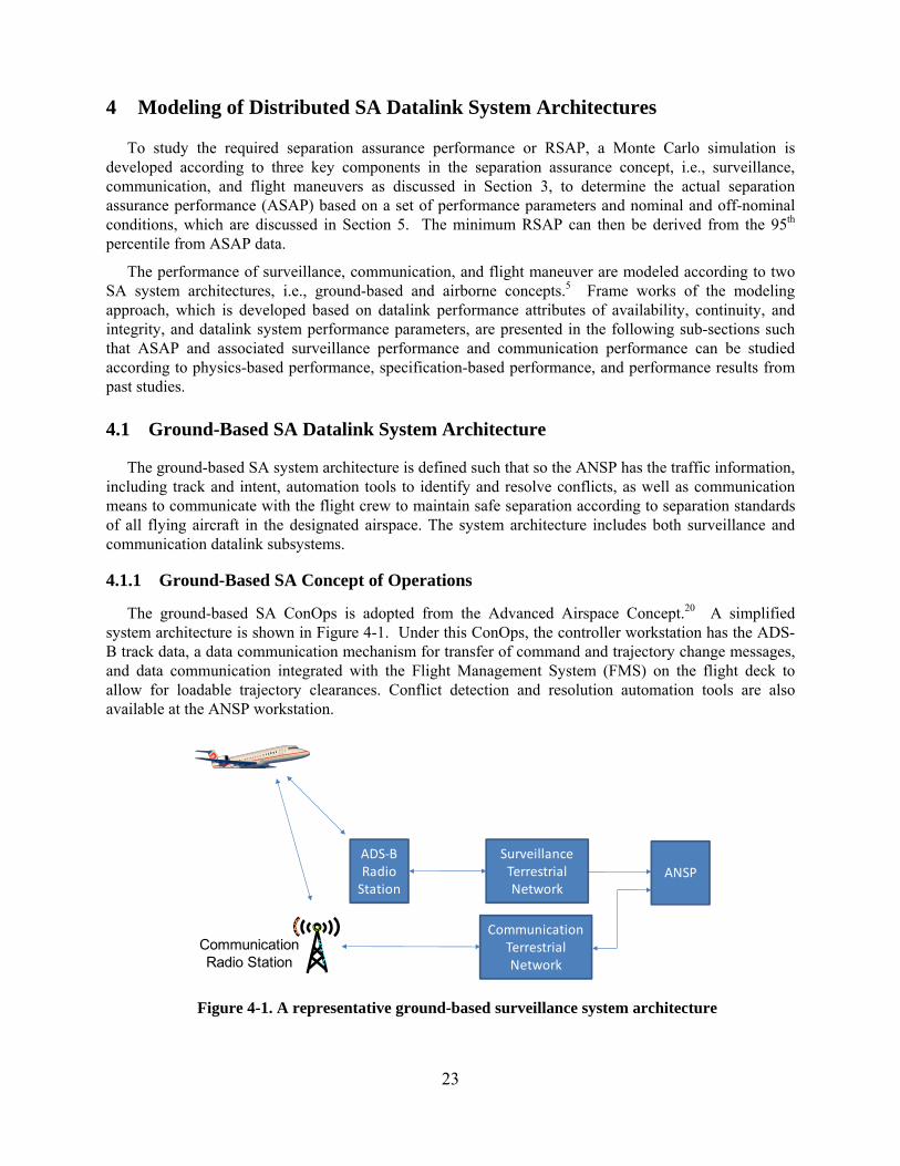
The ground-based SA ConOps is adopted from the Advanced Airspace Concept.20 A simplified system architecture is shown in Figure 4-1. Under this ConOps, the controller workstation has the ADS-B track data, a data communication mechanism for transfer of command and trajectory change messages, and data communication integrated with the Flight Management System (FMS) on the flight deck to allow for loadable trajectory clearances. Conflict detection and resolution automation tools are also available at the ANSP workstation.
ADS‐BRadio Station
SurveillanceTerrestrial Network
CommunicationTerrestrial Network
ANSP
CommunicationRadio Station
Figure 4-1. A representative ground-based surveillance system architecture
24
4.1.2 Assumptions – Ground-Based
The following assumptions are made for the Ground-Based SA ConOps.
The ANSP has the separation assurance (SA) responsibilities, i.e., SA maneuvers are provided by the ANSP
All flight plans are available to the ANSP through a network similar to SWIM The ANSP has tools to perform conflict detection and resolution to maintain safe separation, and
new routes are updated to a shared database All aircraft are ADS-B Out equipped and no Trajectory Change (TC) message is required Datalink communication is the primary SA communication mechanism, i.e., integrated datalink and
FMS equipage Voice communication will be used in UNABLE and emergency scenarios Latency is the only performance parameter to be considered for the terrestrial networks
4.1.3 Modeling Components – Ground-Based
Characteristics of surveillance and datalink communication performance, human response performance during the communication exchanges to complete an SA maneuver, and terrestrial latencies are based on datalink characteristics and published reports and specifications. Probability based system performance metrics and lognormal distribution in representing human response performance are applied in the Monte Carlo simulation to quantify the actual separation assurance performance (ASAP), where time for the surveillance, communication, and maneuver are measured according to specific test conditions.
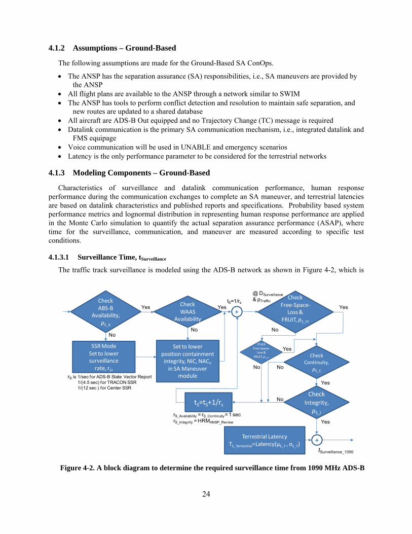
4.1.3.1 Surveillance Time, tSurveillance
The traffic track surveillance is modeled using the ADS-B network as shown in Figure 4-2, which is
Terrestrial LatencyTS_Terrestrial=Latency(μS_T , σS_T)
+tSurveillance_1090
@ DSurveillance
& ρTrafficCheckABS‐B
Availability,pS_A
SSR ModeSet to lowersurveillance rate, rS,
CheckFree‐Space‐
Loss & FRUIT, pS_FF
tS=1/rs
tS=tS+1/rs
+Yes Yes Yes
No NoNo
Set to lowerposition containment integrity, NIC, NACV
in SA Maneuver module
CheckWAAS
Availability
CheckIntegrity,
pS_I
CheckContinuity,
pS_C
Yes
Yes
No
No
rS is 1/sec for ADS-B State Vector Report1/(4.5 sec) for TRACON SSR1/(12 sec ) for Center SSR
rS_Availability = rS_Continuity= 1 secrS_Integrity = HRMANSP_Review
CheckFree‐Space‐
Loss & FRUIT, pS_FF
Yes
No
Figure 4-2. A block diagram to determine the required surveillance time from 1090 MHz ADS-B
25
simplified from Figure 2-3 to objectively quantify the surveillance time, tSurveillance_1090, needed using the 1090 MHz datalink to establish a track. The model considers availability, continuity, and integrity performance as defined in RTCA DO-242A,3 where availability for the ADS-B transmission and receipt are 0.9995 or a combined availability of 0.999 (pS_A), continuity (pS_C) is 0.9998 per flight hour, and integrity (pS_I) is 1-10-6 per ADS-B report. Detection of data corruption is performed by a higher level application or a human operator.
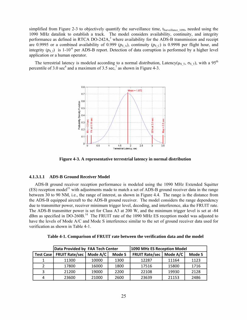
The terrestrial latency is modeled according to a normal distribution, Latency(μS_T, σS_T), with a 95th percentile of 3.0 sec8 and a maximum of 3.5 sec,7 as shown in Figure 4-3.
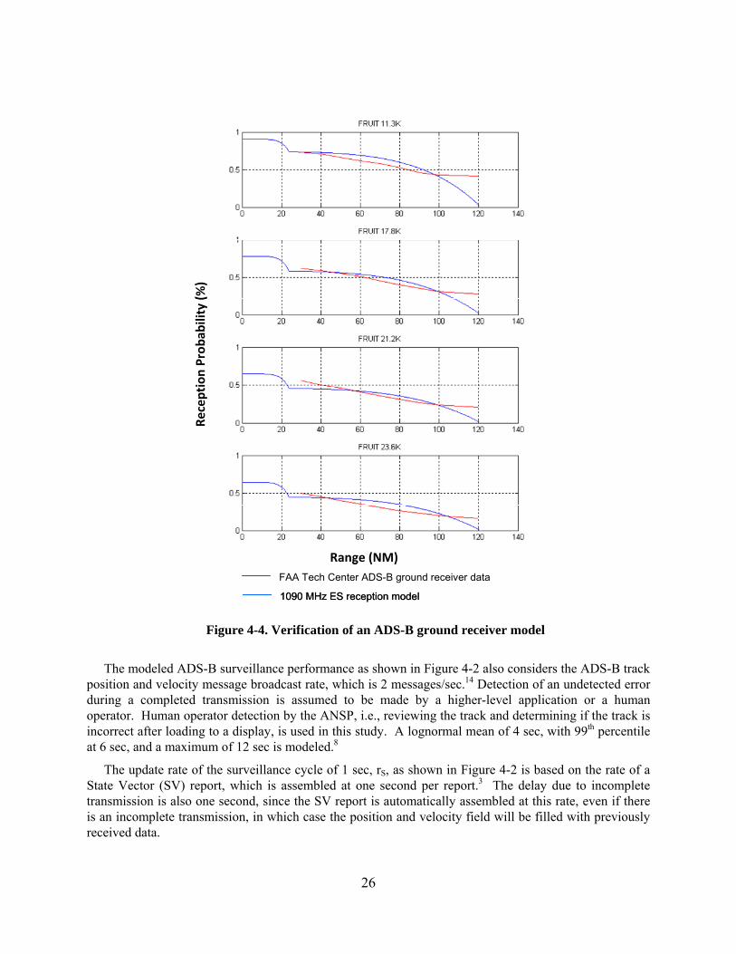
4.1.3.1.1 ADS-B Ground Receiver Model
ADS-B ground receiver reception performance is modeled using the 1090 MHz Extended Squitter (ES) reception model21 with adjustments made to match a set of ADS-B ground receiver data in the range between 30 to 90 NM, i.e., the range of interest, as shown in Figure 4.4. The range is the distance from the ADS-B equipped aircraft to the ADS-B ground receiver. The model considers the range dependency due to transmitter power, receiver minimum trigger level, decoding, and interference, aka the FRUIT rate. The ADS-B transmitter power is set for Class A3 at 200 W, and the minimum trigger level is set at -84 dBm as specified in DO-260B.14 The FRUIT rate of the 1090 MHz ES reception model was adjusted to have the levels of Mode A/C and Mode S interference similar to the set of ground receiver data used for verification as shown in Table 4-1.
Table 4-1. Comparison of FRUIT rate between the verification data and the model
Figure 4-3. A representative terrestrial latency in normal distribution
Data Provided by FAA Tech Center 1090 MHz ES Reception Model
Test Case FRUIT Rate/sec Mode A/C Mode S FRUIT Rate/sec Mode A/C Mode S
1 11300 10000 1300 12287 11164 1123
2 17800 16000 1800 17516 15800 1716
3 21200 19000 2200 22108 19930 2128
4 23600 21000 2600 23639 21153 2486
26
The modeled ADS-B surveillance performance as shown in Figure 4-2 also considers the ADS-B track position and velocity message broadcast rate, which is 2 messages/sec.14 Detection of an undetected error during a completed transmission is assumed to be made by a higher-level application or a human operator. Human operator detection by the ANSP, i.e., reviewing the track and determining if the track is incorrect after loading to a display, is used in this study. A lognormal mean of 4 sec, with 99th percentile at 6 sec, and a maximum of 12 sec is modeled.8
The update rate of the surveillance cycle of 1 sec, rS, as shown in Figure 4-2 is based on the rate of a State Vector (SV) report, which is assembled at one second per report.3 The delay due to incomplete transmission is also one second, since the SV report is automatically assembled at this rate, even if there is an incomplete transmission, in which case the position and velocity field will be filled with previously received data.
Range (NM)
Reception Probab
ility (%)
FAA Tech Center ADS-B ground receiver data
1090 MHz ES reception model
Range (NM)
Reception Probab
ility (%)
Range (NM)
Reception Probab
ility (%)
FAA Tech Center ADS-B ground receiver data
1090 MHz ES reception model
Figure 4-4. Verification of an ADS-B ground receiver model
27
4.1.3.1.2 Off-Nominal Conditions
The following off-nominal conditions are considered in determining the required surveillance time, tSurveillance_1090, as shown in Figure 4-2.
1. Failure of the ADS-B transmission and receiving systems: When ADS-B systems, e.g., GPS or ADS-B receiver malfunctions, the fall-back of the surveillance system is the secondary surveillance radar (SSR). Surveillance systems failure is characterized by availability (pS_A). The scan rate of SSR is considered in determining the required surveillance time, tSurveillance_1090. The accuracy of SSR will affect the CDZ as discussed in Section 3 and is modeled according to Table 4-2.
2. When GPS accuracy is changed by applying a correction technology, i.e., WAAS, Selective Availability off or on, then CDZ is adjusted according to corresponding NIC and NACV values as shown in Table 4-2.
Table 4-2. Surveillance uncertainty and accuracy
Additional off-nominal operational procedures, which may have an impact on the surveillance time, are also being considered. Figure 4-5 shows two independent dependencies on surveillance time other than the 1090 MHz ADS-B track. The first is a scenario requiring additional coordination among ground ATC facilities to send the required intent information to the SA automation tools. In this case, a modified flight plan or clearance for another flight may have an undetected separation conflict with a particular flight. Such information may take several ATC coordination nodes, n, to enter the air traffic management automation tools before it is detected that a separation maneuver is required. The parameter n is randomly selected according to the following rule: n=0 at 80%, n=1 at 15%, and n=2 at 5%. A probability of p11 is given for such occurrences, where p11=2% is selected as the baseline. Latency at the Host Computer and ANSP Workstation is estimated at 1 sec each.
The second off-nominal procedure is a scenario where the ANSP is slow in manually entering the intent information due to a lapse. This scenario is given a probability of 1-p1, where p1 is the probability that the surveillance data are provided by 1090 MHz ADS-B messages, and the time lapse, ANSPLAPSE, is modeled by a normal distribution latency represented by a mean of μL and a standard deviation of σL, Latency(μL, σL), at 15 sec and 3 sec, respectively. The parameter setting p1 = 99.9% is selected as the baseline.
4.1.3.2 Communication Time, tCommunication
A VDL-2 based datalink communication model is developed to determine the communication time, tCommunication, needed to complete an SA communication transaction between the ANSP and the flight crew. A representative flow of communication exchanges between the ground and the flight deck after a
NIC NACv
RC
Horizontal Velocity
Error (95%)
Vertical Geometric
Velocity Error (95%)
WAAS 10 * <25 m 2* <3m/s <15 ft/sec
Selective Aavailability ‐ off 9* <75 m 2*
Selective Aavailability ‐ on 7* <0.2 NM 1* <10m/s <50 ft/sec
TRACON SSR 6 (RNP‐0.3)** <0.6 NM 1**
Center SSR 4 (RNP‐1)** <2 NM 1**
* DO‐242A (ref. 3)
** NAS‐SR‐1000 (ref. 8)
28
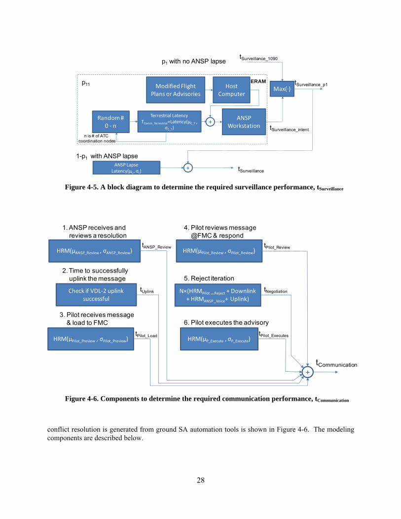
conflict resolution is generated from ground SA automation tools is shown in Figure 4-6. The modeling components are described below.
tSurveillance_1090
tSurveillance_intent
p1 with no ANSP lapse
1-p1 with ANSP lapseANSP Lapse
Latency(μL , σL)+ tSurveillance
Max(∙)tSurveillance_p1Modified Flight
Plans or Advisories
ANSPWorkstation
HostComputer
Terrestrial LatencyTComm_Terrestrial=Latency(μC_T ,
σC_T)
ERAM
+Random #
0 ‐ n
n is # of ATC coordination nodes
p11
Figure 4-5. A block diagram to determine the required surveillance performance, tSurveillance
HRM(μANSP_Review , σANSP_Review)
1. ANSP receives and reviews a resolution
Check if VDL‐2 uplinksuccessful
2. Time to successfullyuplink the message
HRM(μPilot_Preview , σPilot_Preview)
3. Pilot receives message& load to FMC
HRM(μPilot_Review , σPilot_Review)
4. Pilot reviews message@FMC & respond
N×(HRMPilot _Reject + Downlink + HRMANSP _Voice+ Uplink)
5. Reject iteration
HRM(μP_Execute , σP_Execute)
6. Pilot executes the advisory
+
tANSP_Review
tUplink
tPilot_Load
tPilot_Review
tNegotiation
tPilot_Executes
tCommunication
Figure 4-6. Components to determine the required communication performance, tCommunication
29
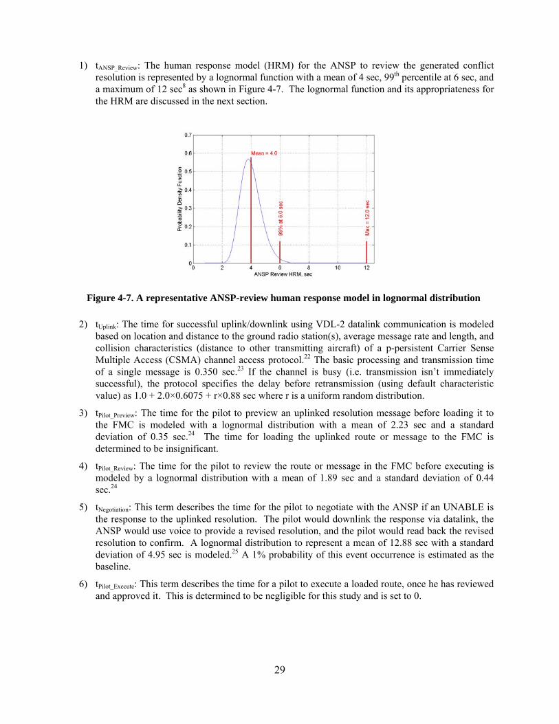
1) tANSP_Review: The human response model (HRM) for the ANSP to review the generated conflict resolution is represented by a lognormal function with a mean of 4 sec, 99th percentile at 6 sec, and a maximum of 12 sec8 as shown in Figure 4-7. The lognormal function and its appropriateness for the HRM are discussed in the next section.
2) tUplink: The time for successful uplink/downlink using VDL-2 datalink communication is modeled based on location and distance to the ground radio station(s), average message rate and length, and collision characteristics (distance to other transmitting aircraft) of a p-persistent Carrier Sense Multiple Access (CSMA) channel access protocol.22 The basic processing and transmission time of a single message is 0.350 sec.23 If the channel is busy (i.e. transmission isn’t immediately successful), the protocol specifies the delay before retransmission (using default characteristic value) as 1.0 + 2.0×0.6075 + r×0.88 sec where r is a uniform random distribution.
3) tPilot_Preview: The time for the pilot to preview an uplinked resolution message before loading it to the FMC is modeled with a lognormal distribution with a mean of 2.23 sec and a standard deviation of 0.35 sec.24 The time for loading the uplinked route or message to the FMC is determined to be insignificant.
4) tPilot_Review: The time for the pilot to review the route or message in the FMC before executing is modeled by a lognormal distribution with a mean of 1.89 sec and a standard deviation of 0.44 sec.24
5) tNegotiation: This term describes the time for the pilot to negotiate with the ANSP if an UNABLE is the response to the uplinked resolution. The pilot would downlink the response via datalink, the ANSP would use voice to provide a revised resolution, and the pilot would read back the revised resolution to confirm. A lognormal distribution to represent a mean of 12.88 sec with a standard deviation of 4.95 sec is modeled.25 A 1% probability of this event occurrence is estimated as the baseline.
6) tPilot_Execute: This term describes the time for a pilot to execute a loaded route, once he has reviewed and approved it. This is determined to be negligible for this study and is set to 0.
Figure 4-7. A representative ANSP-review human response model in lognormal distribution
30
4.1.3.2.1 HRM – Human Response Model
The HRM approximates the statistical time distribution that a pilot or controller would take to perform a specific task. Based on the results of Sheridan26 and Consiglio24, a lognormal distribution is a good fit to the typical probability density for human response time as shown in Equation 8.
HRM(μ,σ)=lnN(μ,σ) (8)
where μ and σ are the mean and standard deviation of the underlying normal distribution, N. The distribution is right-skewed and always greater than zero. This is an appropriate distribution if a variable can be thought of as the multiplicative product of many independent random variables, each of which is positive. Multiple elements of pilot response delay are well fit by log-normal distributions in ref. 24 and are used as applicable in this model. An example is shown in Figure 4-7 for an ANSP reviewing a resolution performance.
4.1.3.2.2 VDL-2 Reception Model
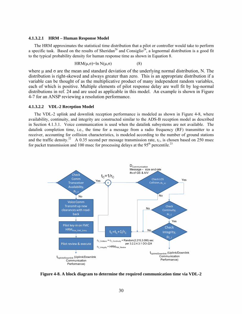
The VDL-2 uplink and downlink reception performance is modeled as shown in Figure 4-8, where availability, continuity, and integrity are constructed similar to the ADS-B reception model as described in Section 4.1.3.1. Voice communication is used when the datalink subsystems are not available. The datalink completion time, i.e., the time for a message from a radio frequency (RF) transmitter to a receiver, accounting for collision characteristics, is modeled according to the number of ground stations and the traffic density.22 A 0.35 second per message transmission rate, rC, is chosen based on 250 msec for packet transmission and 100 msec for processing delays at the 95th percentile.23
tUplink/Downlink (Uplink/DownlinkCommunicationPerformance)
DCommunicationMessage – size and rate#s of GS & A/V
CheckComm
Transceiver Availability,
pC_A
Check LOSCollision, pC_FC
tC=1/rC
tC=tC+1/rC
+Yes Yes
NoNo
CheckIntegrity,
pC_I
CheckContinuity,
pC_C
Yes
No
No
rC_Collision = rC_Continuity = Random(2.215,3.095) secper 3.2.2.4.3.1 DO-224
rC_Integrity = HRMPilot_Review
Voice CommTransmit up new
clearances with read‐back
Pilot key‐in on FMCHRMPilot_FMC_Entry
Pilot review & execute
tUplink/Downlink (Uplink/DownlinkCommunicationPerformance)
Figure 4-8. A block diagram to determine the required communication time via VDL-2
31
4.1.3.3 Maneuver Time, tManeuver
The dynamic performance of the aircraft from maneuver initiation until closest point of approach is modeled with a simple, but realistic, model for both the lateral offset and vertical offset maneuvers.
4.1.3.3.1 Lateral Offset Maneuver
The lateral offset maneuver time is determined by the time required to initiate, change, and capture a new heading plus the time to reach the CPA. As indicated earlier, the CPA for a lateral offset maneuver is the tangent point of the relative flight path to the CDZ after the heading change. It is assumed that the entire maneuver is conducted at a constant ground speed. The initiation, change, and capture of the new heading is approximated as the summation of
1. 1.5 second initiation of turn
2. 1 sec turn at bank angle of 15 degrees (rolling into turn)
3. N sec turn at bank angle of 30 degrees
4. 1 sec turn at bank angle of 15 degrees (rolling out of turn)
5. 1.5 second new heading capture
The rate of change of heading in steps 2 through 4 is calculated from the ground speed. The time length of step 3 is adjusted to complete the necessary heading change given the rate of change of heading in each step. For this study, the overall heading change is fixed at 15 degrees. After determining the distance travelled during the heading change, the time needed to traverse the remaining distance to the CPA at the fixed ground speed is determined and added to the previous times to determine the total lateral offset maneuver time.
No specific probabilistic elements are included in the calculation of lateral offset maneuver time. The only uncertainty comes from the size of CDZ and therefore the length of time needed to clear the CDZ at the CPA. The effects of winds were not modeled.
4.1.3.3.2 Vertical Offset Maneuver
The vertical offset maneuver time is determined by the time required to transition the aircraft 1000 ft of altitude, the standard vertical separation below FL 290 and above FL 290 for RVSM. The time is calculated using a single average rate of climb/descent over the entire altitude with no transition times at either end. The rate of climb is selected by engineering estimate from a normal distribution with a mean value of 1000 ft/min and a standard deviation of 200 ft/min. An upper bound of 2000 ft/min and a lower bound of 500ft/min are enforced as rates of climb/descent outside these values would be rejected by the ANSP.
4.1.3.4 Modeling Summary
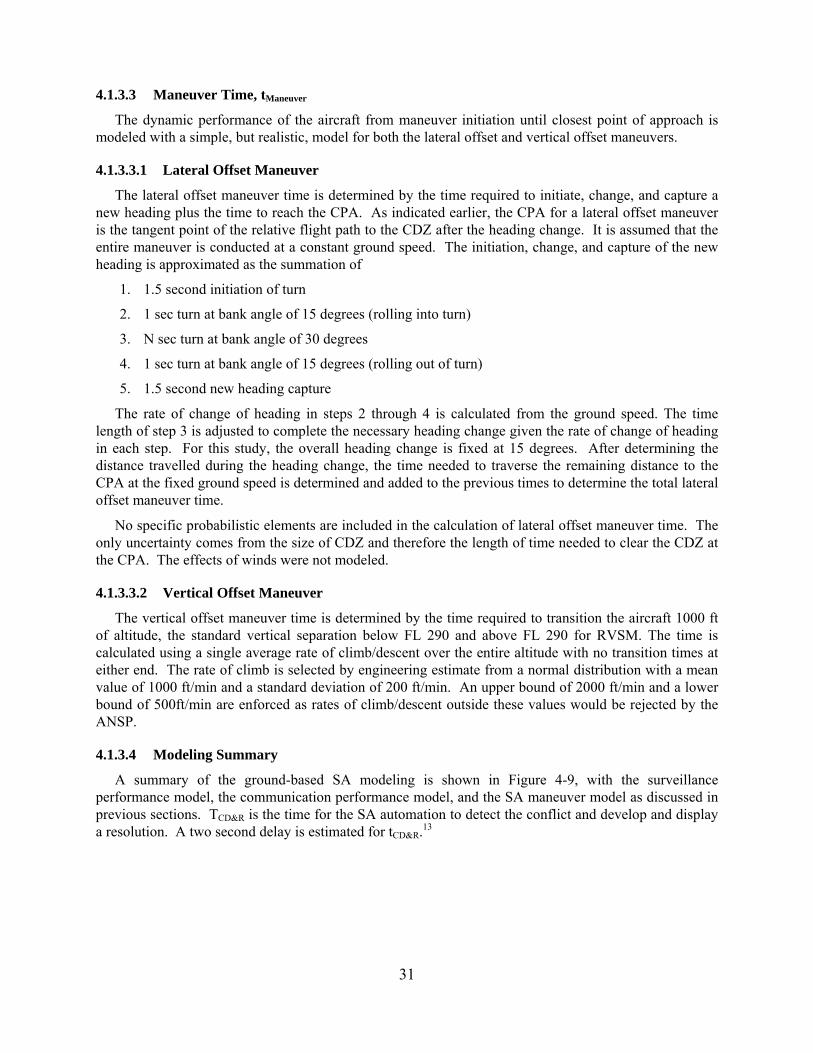
A summary of the ground-based SA modeling is shown in Figure 4-9, with the surveillance performance model, the communication performance model, and the SA maneuver model as discussed in previous sections. TCD&R is the time for the SA automation to detect the conflict and develop and display a resolution. A two second delay is estimated for tCD&R.13
32
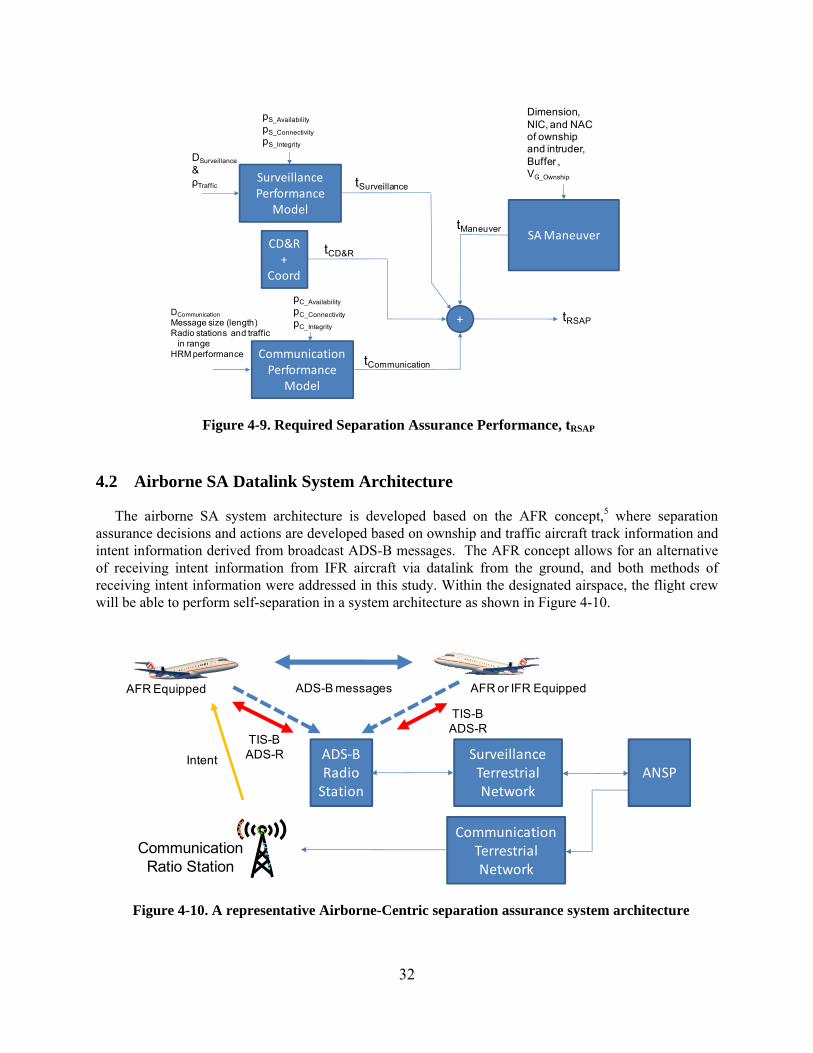
4.2 Airborne SA Datalink System Architecture
The airborne SA system architecture is developed based on the AFR concept,5 where separation assurance decisions and actions are developed based on ownship and traffic aircraft track information and intent information derived from broadcast ADS-B messages. The AFR concept allows for an alternative of receiving intent information from IFR aircraft via datalink from the ground, and both methods of receiving intent information were addressed in this study. Within the designated airspace, the flight crew will be able to perform self-separation in a system architecture as shown in Figure 4-10.
SurveillancePerformance
Model
DSurveillance
&ρTraffic
pS_Availability
pS_Connectivity
pS_Integrity
CD&R +
Coord
CommunicationPerformance
Model
DCommunication
Message size (length)Radio stations and traffic
in rangeHRM performance
pC_Availability
pC_Connectivity
pC_Integrity
SA Maneuver
Dimension,NIC, and NACof ownship and intruder,Buffer ,VG_Ownship
+ tRSAP
tSurveillance
tCD&R
tCommunication
tManeuver
Figure 4-9. Required Separation Assurance Performance, tRSAP
AFR Equipped AFR or IFR Equipped
ADS‐BRadio Station
SurveillanceTerrestrial Network
ANSP
ADS-B messages
TIS-BADS-R
TIS-BADS-R
CommunicationTerrestrial Network
CommunicationRatio Station
Intent
Figure 4-10. A representative Airborne-Centric separation assurance system architecture
33
4.2.1 Airborne SA Concept of Operations
Under AFR, the flight crew and the airplane that is certified for AFR will have the capability to perform self-separation in a designated airspace with mixed-equipped traffic, i.e., IFR and/or AFR. An onboard Airborne Separation Assistance System (ASAS)17 provides pilots with information on the conflicts, alerts, and resolutions, and provides an interface for pilots to select and load resolution maneuvers into the FMS or execute resolutions through tactical flight controls.
4.2.2 Assumptions – Airborne Concept
The following modeling assumptions are made for the Airborne SA ConOps.
The AFR-equipped airplane performs self-separation without ANSP separation services.
AFR flight crews have automation tools certified by the FAA for self-separation.
IFR traffic has the right-of-way.
Intent messages are essential to AFR operations.
A maximum of four-TC messages broadcast will be required.
As an alternative, IFR flight plans or intent will be uplinked to AFR via datalink per request.
No communication with the ANSP is required for SA.
4.2.3 Modeling Components – Airborne Concept
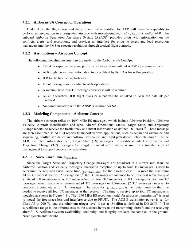
The airborne concept relies on 1090 MHz ES messages, which include Airborne Position, Airborne Velocity, Aircraft Identification and type, Aircraft Operational Status, Target State, and Trajectory Change reports, to receive the traffic track and intent information as defined DO-260B.14 These message are then assembled as ADS-B reports to support various applications, such as separation assurance and sequencing, conflict avoidance and collision avoidance, and flight path deconfliction planning.3 For the AFR, the intent information, i.e., Target State (TS) messages for short-term intent information and Trajectory Change (TC) messages for long-term intent information, is used in automated conflict management to support cooperative separation.
4.2.3.1 Surveillance Time, tSurveillance
Since the Target State and Trajectory Change messages are broadcast at a slower rate than the Airborne Position and Velocity messages, successful reception of up to four TC messages is used to determine the required surveillance time, tSurveillance_Intent, for the baseline case. To meet the maximum ADS-B broadcast rate of 6.2 messages/sec,14 the TC messages are assumed to be broadcast sequentially at a rate of 0.8 messages/sec or 0.2 message/sec for four TC messages or 0.4 message/sec for two TC messages, which leads to a five-second (4 TC messages) or 2.5-second (2 TC messages) interval to broadcast a complete set of TC messages. The value for tSurveillance_Intent is then determined by the time needed to receive all four TC messages at the receiver. The time to receive up to four TC messages is modeled as shown in Figure 4-11. The 1090 MHz ES reception model for airborne transmission19 is used to model the free-space-loss and interference due to FRUIT. The ADS-B transmitter power is set for Class A3 at 200 W, and the minimum trigger level is set at -84 dBm as defined in DO-260B.14 The surveillance range in the airborne case is the distance between the transmitting aircraft and the receiving aircraft. Surveillance system availability, continuity, and integrity are kept the same as in the ground-based system architecture.
34
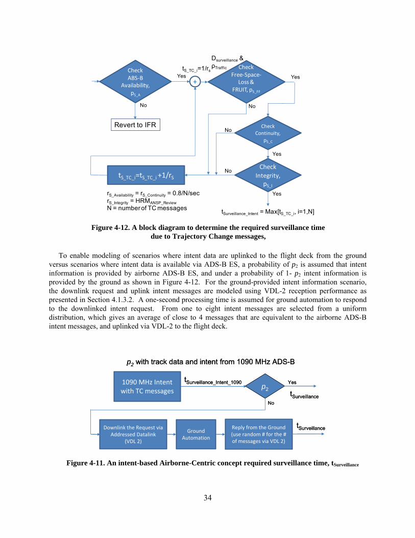
To enable modeling of scenarios where intent data are uplinked to the flight deck from the ground versus scenarios where intent data is available via ADS-B ES, a probability of p2 is assumed that intent information is provided by airborne ADS-B ES, and under a probability of 1- p2 intent information is provided by the ground as shown in Figure 4-12. For the ground-provided intent information scenario, the downlink request and uplink intent messages are modeled using VDL-2 reception performance as presented in Section 4.1.3.2. A one-second processing time is assumed for ground automation to respond to the downlinked intent request. From one to eight intent messages are selected from a uniform distribution, which gives an average of close to 4 messages that are equivalent to the airborne ADS-B intent messages, and uplinked via VDL-2 to the flight deck.
1090 MHz Intent with TC messages
Downlink the Request via Addressed Datalink
(VDL 2)
Reply from the Ground(use random # for the # of messages via VDL 2)
tSurveillance_Intent_1090
p2 with track data and intent from 1090 MHz ADS-B
tSurveillance
p2
Yes
No
tSurveillance
GroundAutomation
1090 MHz Intent with TC messages
Downlink the Request via Addressed Datalink
(VDL 2)
Reply from the Ground(use random # for the # of messages via VDL 2)
tSurveillance_Intent_1090
p2 with track data and intent from 1090 MHz ADS-B
tSurveillance
p2
Yes
No
tSurveillance
GroundAutomation
Figure 4-11. An intent-based Airborne-Centric concept required surveillance time, tSurveillance
CheckABS‐B
Availability,pS_A
CheckFree‐Space‐
Loss & FRUIT, pS_FF
tS_TC_i=1/rs
tS_TC_i=tS_TC_i +1/rS
+Yes Yes
NoNo
CheckIntegrity,
pS_I
CheckContinuity,
pS_C
Yes
Yes
No
No
Revert to IFR
Dsurveillance &ρTraffic
tSurveillance_Intent = Max[tS_TC_i, i=1,N]
rS_Availability = rS_Continuity = 0.8/N/secrS_Integrity = HRMANSP_Review
N = number of TC messages
Figure 4-12. A block diagram to determine the required surveillance time due to Trajectory Change messages,
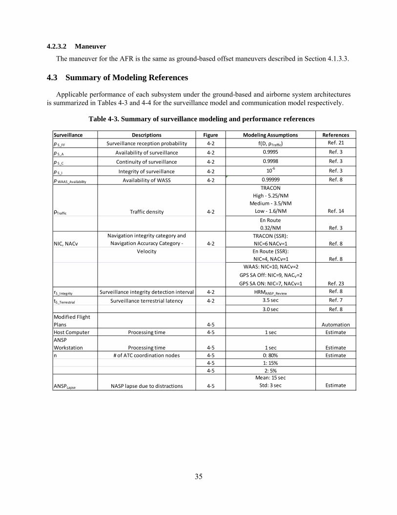
35
4.2.3.2 Maneuver
The maneuver for the AFR is the same as ground-based offset maneuvers described in Section 4.1.3.3.
4.3 Summary of Modeling References
Applicable performance of each subsystem under the ground-based and airborne system architectures is summarized in Tables 4-3 and 4-4 for the surveillance model and communication model respectively.
Table 4-3. Summary of surveillance modeling and performance references
Surveillance Descriptions Figure Modeling Assumptions References
p S_FF Surveillance reception probability 4‐2 f(D, ρTraffic) Ref. 21
p S_A Availability of surveillance 4‐2 0.9995 Ref. 3
p S_C Continuity of surveillance 4‐2 0.9998 Ref. 3
p S_I Integrity of surveillance 4‐2 10‐6
Ref. 3
pWAAS_Availability Availability of WASS 4‐2 0.99999 Ref. 8
ρTraffic Traffic density 4‐2
TRACON
High ‐ 5.25/NM
Medium ‐ 3.5/NM
Low ‐ 1.6/NM Ref. 14
En Route
0.32/NM Ref. 3
NIC, NACv
Navigation integrity category and
Navigation Accuracy Category ‐ 4‐2
TRACON (SSR):
NIC=6 NACv=1 Ref. 8
Velocity En Route (SSR):
NIC=4, NACv=1 Ref. 8
WAAS: NIC=10, NACv=2
GPS SA Off: NIC=9, NACV=2
GPS SA ON: NIC=7, NACv=1 Ref. 23
rS_Integrity Surveillance integrity detection interval 4‐2 HRMANSP_Review Ref. 8
tS_Terrestrial Surveillance terrestrial latency 4‐2 3.5 sec Ref. 7
3.0 sec Ref. 8
Modified Flight
Plans 4‐5 Automation
Host Computer Processing time 4‐5 1 sec Estimate
ANSP
Workstation Processing time 4‐5 1 sec Estimate
n # of ATC coordination nodes 4‐5 0: 80% Estimate
4‐5 1: 15%
4‐5 2: 5%
ANSPLapse NASP lapse due to distractions 4‐5
Mean: 15 sec
Std: 3 sec Estimate
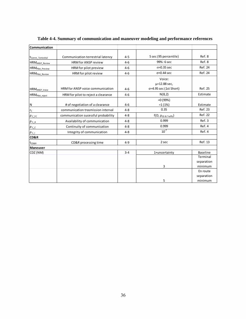
36
Table 4-4. Summary of communication and maneuver modeling and performance references
Communication
tComm_Terrestrial Communication terrestrial latency 4‐5 5 sec (95 percentile) Ref. 8
HRMANSP_Review HRM for ANSP review 4‐6 99%: 6 sec Ref. 8
HRMPilot_Preview HRM for pilot preview 4‐6 σ=0.35 sec Ref. 24
HRMPilot_Review HRM for pilot review 4‐6 σ=0.44 sec Ref. 24
HRMANSP_Voice HRM for ANSP voice communication 4‐6
Voice:
μ=12.88 sec,
σ=4.95 sec (1st Short) Ref. 25
HRMPilot_reject HRM for pilot to reject a clearance 4‐6 N(8,2) Estimate
N # of negotiation of a clearance 4‐6
=0 (99%)
=1 (1%) Estimate
rC communication trasmission interval 4‐8 0.35 Ref. 23
p C_FC communication sucessful probability 4‐8 f(D, ρGS & Traffic) Ref. 22
p C_A Availability of communication 4‐8 0.999 Ref. 3
p C_C Continuity of communication 4‐8 0.999 Ref. 4
p C_I Integrity of communication 4‐8 10‐7
Ref. 4
CD&R
tCD&R CD&R processing time 4‐9 2 sec Ref. 13
Maneuver
CDZ (NM) 3‐4 1+uncertainty Baseline
3
Terminal
separation
minimum
5
En route
separation
minimum
37
5 Test Design
To investigate the required separation assurance performance under the two selected SA system architectures, the focus is on the tradeoff of the key performance parameters associated with the three major elements in both ground-based and airborne concepts of operations. These three elements are surveillance, communication, and maneuver, where surveillance and communication are based on datalink communication under NextGen technology, and maneuver performance depends on both surveillance and communication performance and flight dynamics. Test parameters were developed from characteristics of the system architectures such that subsystem performance sensitivity and tradeoffs could be studied. Each SA system architecture was modeled in MATLAB® based on descriptions discussed in Section 4. A Monte Carlo simulation was developed to execute the test matrix presented in Section 5.1.3.
5.1 Availability, Continutity, and Integrity
The datalink performance metrics of availability, continuity, and integrity in surveillance and communication subsystems were selected according to DO-242A for 1090 MHz surveillance performance, which is defined as 0.9995, 0.9998, and 10-6 with respect to the availability, continuity, and integrity. Availability for communication defined by DO-224B is 0.999. Continuity and integrity performance for the communication system, found in a draft of the FAA’s Final Program Requirements for Data Communications, are 0.999 and 10-7, respectively.4 These values are used as the baseline test case. The developed model is capable of studying the impact of these three parameters on the overall required separation assurance performance.
5.2 Actual Separation Assurance Performance (ASAP)
The tests were developed to calculate the actual separation assurance performance, tASAP, based on a range of test conditions. The Monte Carlo simulation ran 10,000 times for each test condition to establish a statistical database. Each ASAP consists of four performance components, i.e., i) surveillance time to generate CD&R, tSurveillance, ii) processing time for CD&R, tCD&R, iii) communication time to complete an SA communication transaction, tCommunication, and iv) maneuver time for a lateral or vertical offset SA maneuver, tManeuver. The 95th percentile of the tASAP was then used to determine the required separation assurance performance. The required separation assurance performance, tRSRP, is defined in Equation 9. Individual required performance elements are also represented by the 95th percentile values as shown in Equations 10-12. The value of tCD&R is assumed to be a constant at two seconds for this study.
tRSAP = tASAP @95th percentile = (tSurveillance + tCD&R + tCommunication + tManeuver ) @95th percentile (9)
tRequired_Surveilance = tSurveillance @95th percentile (10)
tRequired_Communication = tCommunication @95th percentile (11)
tRequired_Maneuver = tManeuver @95th percentile (12)
5.3 Test Matrix
The following test parameters were developed to investigate their effects on ASAP. Based on the two SA concepts, i.e., ground-based and airborne, a test matrix was developed to include the following test parameters: range, air traffic density, uncertainty and accuracy of the surveillance performance, datalink communication performance, datalink vs. voice communication, ground speed of the ownship, and separation minimum.
38
A medium-density terminal case with a traffic density that is equivalent to the 1999 LA basin14 was chosen as the baseline, and both nominal and off-nominal conditions were evaluated. The test matrix is shown in Table 5-1. Test Cases 0-29 were developed for the ground-based SA system architecture. Test Cases 100-155 were developed for the airborne SA system architecture. The baseline cases, i.e., Test Cases 0 and 100 for ground-based and airborne concepts respectively, also have the availability, continuity, and integrity as defined in Section 5.1.1. For the airborne concept, the surveillance time to acquire 2 intent messages was chosen as the baseline following References 3 and 14 in separation assurance applications.
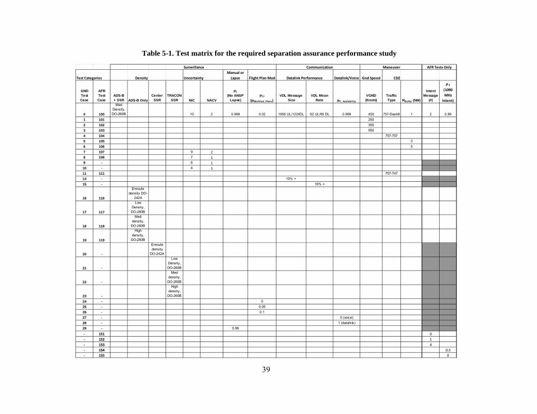
39
Table 5-1. Test matrix for the required separation assurance performance study
Surveillance Communication Maneuver
Test Categories Density Uncertainty
Manual or
Lapse Flight Plan Mod Datalink/Voice Gnd Speed CDZ
GNDTest Case
AFRTest Case
ADS-B+ SSR ADS-B Only
Center SSR
TRACONSSR NIC NACV
p1
(No ANSPLapse)
p11
(pModified_Plans)VDL Message
SizeVDL Mean
Rate pC_Availability
VGND (Knots)
TrafficType RBuffer (NM)
IntentMessage
(#)
p 2
(1090
MHz
Intent)
0 100
Med Density,DO-260B 10 2 0.999 0.02 1856 UL/1224DL 62 UL/85 DL 0.999 450 757-Dash8 1 2 0.99
1 101 250
2 102 350
3 103 550
4 104 757-757
5 105 3
6 106 5
7 107 9 28 108 7 19 - 6 110 - 4 111 111 757-747
14 - 10% +
15 - 10% +
16 116
Enroute density DO-
242A
17 117
Low Density, DO-260B
18 118
Med density,
DO-260B
19 119
High density,
DO-260B
20 -
Enroute density
DO-242A
21 -
Low Density, DO-260B
22 -
Med density,
DO-260B
23 -
High density,
DO-260B
24 - 0
25 - 0.05
26 - 0.1
27 - 0 (voice)
28 - 1 (datalink)
29 - 0.98
‐ 151 0
‐ 152 1
‐ 153 4
‐ 154 0.5
‐ 155 0
AFR Tests Only
Datalink Performance
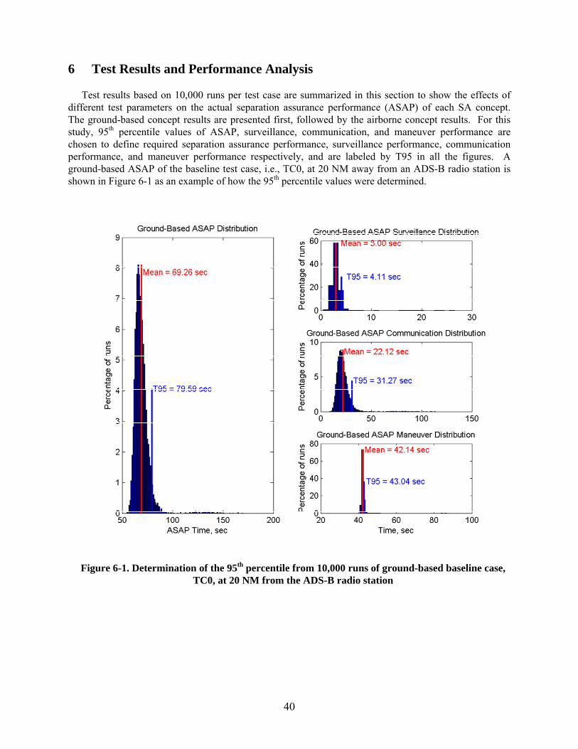
40
6 Test Results and Performance Analysis
Test results based on 10,000 runs per test case are summarized in this section to show the effects of different test parameters on the actual separation assurance performance (ASAP) of each SA concept. The ground-based concept results are presented first, followed by the airborne concept results. For this study, 95th percentile values of ASAP, surveillance, communication, and maneuver performance are chosen to define required separation assurance performance, surveillance performance, communication performance, and maneuver performance respectively, and are labeled by T95 in all the figures. A ground-based ASAP of the baseline test case, i.e., TC0, at 20 NM away from an ADS-B radio station is shown in Figure 6-1 as an example of how the 95th percentile values were determined.
Figure 6-1. Determination of the 95th percentile from 10,000 runs of ground-based baseline case, TC0, at 20 NM from the ADS-B radio station
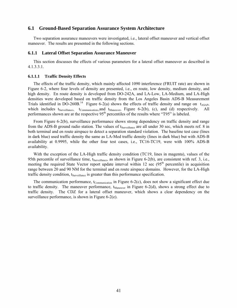
41
6.1 Ground-Based Separation Assurance System Architecture
Two separation assurance maneuvers were investigated, i.e., lateral offset maneuver and vertical offset maneuver. The results are presented in the following sections.
6.1.1 Lateral Offset Separation Assurance Maneuver
This section discusses the effects of various parameters for a lateral offset maneuver as described in 4.1.3.3.1.
6.1.1.1 Traffic Density Effects
The effects of the traffic density, which mainly affected 1090 interference (FRUIT rate) are shown in Figure 6-2, where four levels of density are presented, i.e., en route, low density, medium density, and high density. En route density is developed from DO-242A, and LA-Low, LA-Medium, and LA-High densities were developed based on traffic density from the Los Angeles Basin ADS-B Measurement Trials identified in DO-260B.14 Figure 6-2(a) shows the effects of traffic density and range on tASAP, which includes tSurveillance,, tCommunication,,and tManeuver, Figure 6-2(b), (c), and (d) respectively. All performances shown are at the respective 95th percentiles of the results where “T95” is labeled.
From Figure 6-2(b), surveillance performance shows strong dependency on traffic density and range from the ADS-B ground radio station. The values of tSurveillance are all under 30 sec, which meets ref. 8 in both terminal and en route airspace to detect a separation standard violation. The baseline test case (lines in dark blue) used traffic density the same as LA-Med traffic density (lines in dark blue) but with ADS-B availability at 0.9995, while the other four test cases, i.e., TC16-TC19, were with 100% ADS-B availability.
With the exception of the LA-High traffic density condition (TC19, lines in magenta), values of the 95th percentile of surveillance time, tSurveillance, as shown in Figure 6-2(b), are consistent with ref. 3, i.e., meeting the required State Vector report update interval within 12 sec (95th percentile) in acquisition range between 20 and 90 NM for the terminal and en route airspace domains. However, for the LA-High traffic density condition, tSurveillance is greater than this performance specification.
The communication performance, tCommunication in Figure 6-2(c), does not show a significant effect due to traffic density. The maneuver performance, tManeuver in Figure 6-2(d), shows a strong effect due to traffic density. The CDZ for a lateral offset maneuver, which shows a clear dependency on the surveillance performance, is shown in Figure 6-2(e).
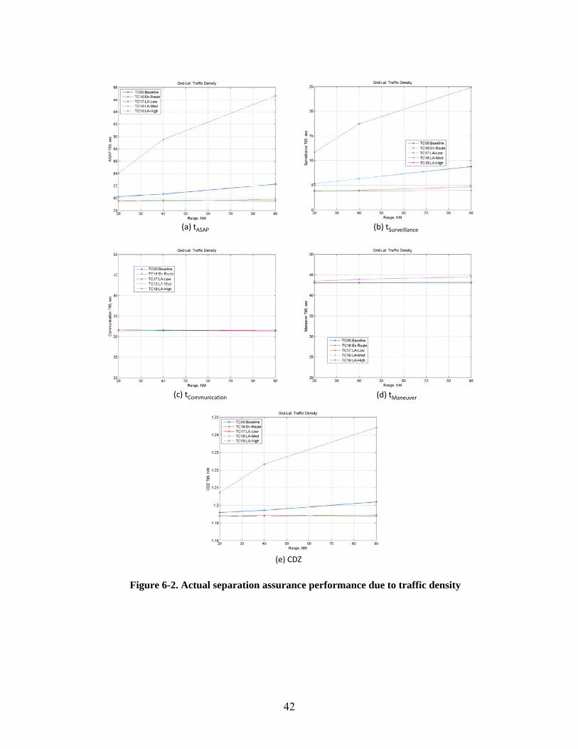
42
(a) tASAP (b) tSurveillance
(c) tCommunication (d) tManeuver
(e) CDZ
Figure 6-2. Actual separation assurance performance due to traffic density
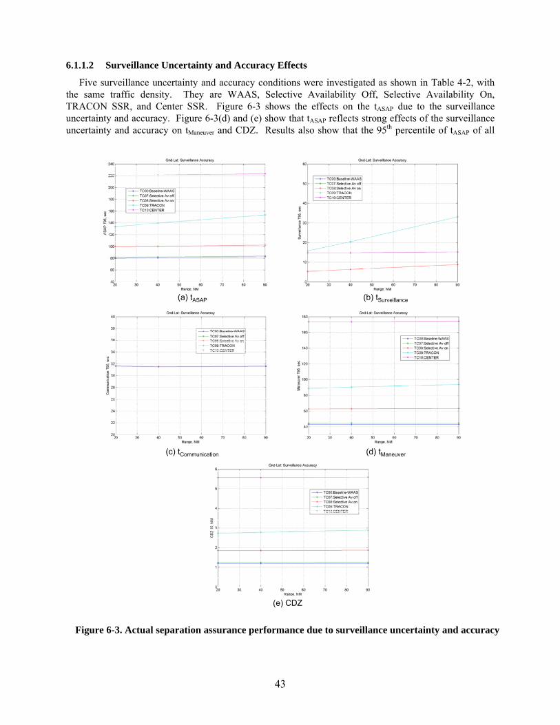
43
6.1.1.2 Surveillance Uncertainty and Accuracy Effects
Five surveillance uncertainty and accuracy conditions were investigated as shown in Table 4-2, with the same traffic density. They are WAAS, Selective Availability Off, Selective Availability On, TRACON SSR, and Center SSR. Figure 6-3 shows the effects on the tASAP due to the surveillance uncertainty and accuracy. Figure 6-3(d) and (e) show that tASAP reflects strong effects of the surveillance uncertainty and accuracy on tManeuver and CDZ. Results also show that the 95th percentile of tASAP of all
(e) CDZ
(a) tASAP
(c) tCommunication (d) tManeuver
(b) tSurveillance
Figure 6-3. Actual separation assurance performance due to surveillance uncertainty and accuracy
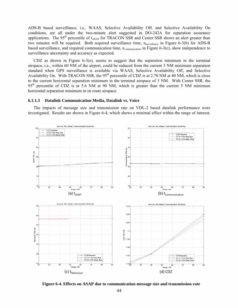
44
ADS-B based surveillance, i.e., WAAS, Selective Availability Off, and Selective Availability On conditions, are all under the two-minute alert suggested in DO-242A for separation assurance applications. The 95th percentile of tASAP for TRACON SSR and Center SSR shows an alert greater than two minutes will be required. Both required surveillance time, tSurveillance in Figure 6-3(b) for ADS-B based surveillance, and required communication time, tCommunication in Figure 6-3(c), show independence to surveillance uncertainty and accuracy as expected.
CDZ as shown in Figure 6-3(e), seems to suggest that the separation minimum in the terminal airspace, i.e., within 60 NM of the airport, could be reduced from the current 3 NM minimum separation standard when GPS surveillance is available via WAAS, Selective Availability Off, and Selective Availability On. With TRACON SSR, the 95th percentile of CDZ is at 2.78 NM at 40 NM, which is close to the current horizontal separation minimum in the terminal airspace of 3 NM. With Center SSR, the 95th percentile of CDZ is at 5.6 NM at 90 NM, which is greater than the current 5 NM minimum horizontal separation minimum in en route airspace.
6.1.1.3 Datalink Communication Media, Datalink vs. Voice
The impacts of message size and transmission rate on VDL-2 based datalink performance were investigated. Results are shown in Figure 6-4, which shows a minimal effect within the range of interest,
(a) tASAP (b) tCommunication
(c) tManeuver (d) CDZ
Figure 6-4. Effects on ASAP due to communication message size and transmission rate
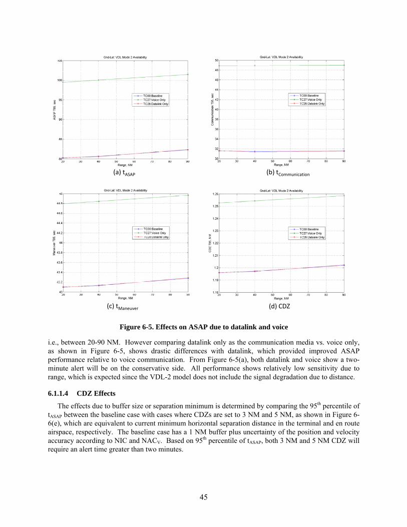
45
i.e., between 20-90 NM. However comparing datalink only as the communication media vs. voice only, as shown in Figure 6-5, shows drastic differences with datalink, which provided improved ASAP performance relative to voice communication. From Figure 6-5(a), both datalink and voice show a two-minute alert will be on the conservative side. All performance shows relatively low sensitivity due to range, which is expected since the VDL-2 model does not include the signal degradation due to distance.
6.1.1.4 CDZ Effects
The effects due to buffer size or separation minimum is determined by comparing the 95th percentile of tASAP between the baseline case with cases where CDZs are set to 3 NM and 5 NM, as shown in Figure 6-6(e), which are equivalent to current minimum horizontal separation distance in the terminal and en route airspace, respectively. The baseline case has a 1 NM buffer plus uncertainty of the position and velocity accuracy according to NIC and NACV. Based on 95th percentile of tASAP, both 3 NM and 5 NM CDZ will require an alert time greater than two minutes.
(a) tASAP (b) tCommunication
(c) tManeuver (d) CDZ
Figure 6-5. Effects on ASAP due to datalink and voice
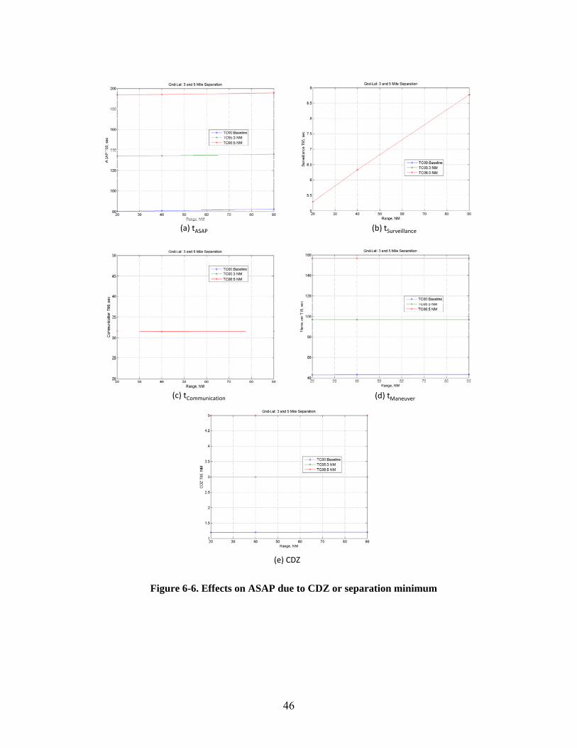
46
(a) tASAP (b) tSurveillance
(c) tCommunication (d) tManeuver
(e) CDZ
Figure 6-6. Effects on ASAP due to CDZ or separation minimum
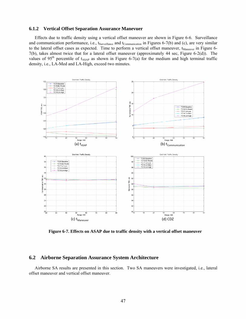
47
6.1.2 Vertical Offset Separation Assurance Manevuer
Effects due to traffic density using a vertical offset maneuver are shown in Figure 6-6. Surveillance and communication performance, i.e., tSurveillance and tCommunication in Figures 6-7(b) and (c), are very similar to the lateral offset cases as expected. Time to perform a vertical offset maneuver, tManeuver in Figure 6-7(b), takes almost twice that for a lateral offset maneuver (approximately 44 sec, Figure 6-2(d)). The values of 95th percentile of tASAP as shown in Figure 6-7(a) for the medium and high terminal traffic density, i.e., LA-Med and LA-High, exceed two minutes.
6.2 Airborne Separation Assurance System Architecture
Airborne SA results are presented in this section. Two SA maneuvers were investigated, i.e., lateral offset maneuver and vertical offset maneuver.
(a) tASAP (b) tCommunication
(c) tManeuver (d) CDZ
Figure 6-7. Effects on ASAP due to traffic density with a vertical offset maneuver
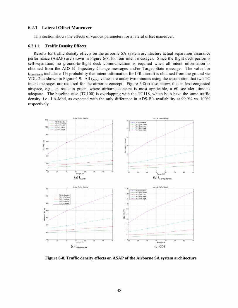
48
6.2.1 Lateral Offset Maneuver
This section shows the effects of various parameters for a lateral offset maneuver.
6.2.1.1 Traffic Density Effects
Results for traffic density effects on the airborne SA system architecture actual separation assurance performance (ASAP) are shown in Figure 6-8, for four intent messages. Since the flight deck performs self-separation, no ground-to-flight deck communication is required when all intent information is obtained from the ADS-B Trajectory Change messages and/or Target State message. The value for tSurveillance includes a 1% probability that intent information for IFR aircraft is obtained from the ground via VDL-2 as shown in Figure 4-9. All tASAP values are under two minutes using the assumption that two TC intent messages are required for the airborne concept. Figure 6-8(a) also shows that in less congested airspace, e.g., en route in green, where airborne concept is most applicable, a 60 sec alert time is adequate. The baseline case (TC100) is overlapping with the TC118, which both have the same traffic density, i.e., LA-Med, as expected with the only difference in ADS-B’s availability at 99.9% vs. 100% respectively.
(a) tASAP (b) tSurveillance
(c) tManeuver (d) CDZ
Figure 6-8. Traffic density effects on ASAP of the Airborne SA system architecture
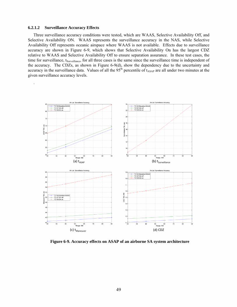
49
6.2.1.2 Surveillance Accuracy Effects
Three surveillance accuracy conditions were tested, which are WAAS, Selective Availability Off, and Selective Availability ON. WAAS represents the surveillance accuracy in the NAS, while Selective Availability Off represents oceanic airspace where WAAS is not available. Effects due to surveillance accuracy are shown in Figure 6-9, which shows that Selective Availability On has the largest CDZ relative to WAAS and Selective Availability Off to ensure separation assurance. In these test cases, the time for surveillance, tSurveillance, for all three cases is the same since the surveillance time is independent of the accuracy. The CDZs, as shown in Figure 6-9(d), show the dependency due to the uncertainty and accuracy in the surveillance data. Values of all the 95th percentile of tASAP are all under two minutes at the given surveillance accuracy levels.
.
(a) tASAP (b) tSurveillance
(c) tManeuver (d) CDZ
Figure 6-9. Accuracy effects on ASAP of an airborne SA system architecture
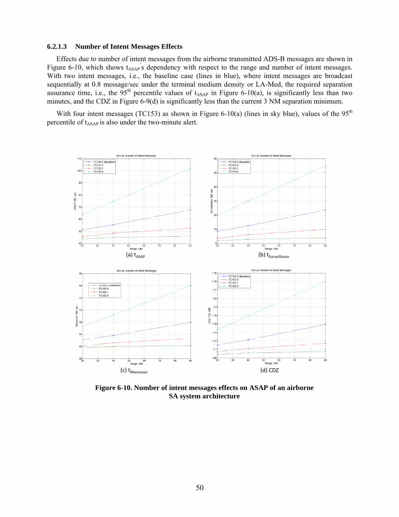
50
6.2.1.3 Number of Intent Messages Effects
Effects due to number of intent messages from the airborne transmitted ADS-B messages are shown in Figure 6-10, which shows tASAP
’s dependency with respect to the range and number of intent messages. With two intent messages, i.e., the baseline case (lines in blue), where intent messages are broadcast sequentially at 0.8 message/sec under the terminal medium density or LA-Med, the required separation assurance time, i.e., the 95th percentile values of tASAP in Figure 6-10(a), is significantly less than two minutes, and the CDZ in Figure 6-9(d) is significantly less than the current 3 NM separation minimum.
With four intent messages (TC153) as shown in Figure 6-10(a) (lines in sky blue), values of the 95th percentile of tASAP is also under the two-minute alert.
(a) tASAP (b) tSurveillance
(c) tManeuver (d) CDZ
Figure 6-10. Number of intent messages effects on ASAP of an airborne SA system architecture
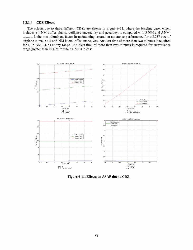
51
6.2.1.4 CDZ Effects
The effects due to three different CDZs are shown in Figure 6-11, where the baseline case, which includes a 1 NM buffer plus surveillance uncertainty and accuracy, is compared with 3 NM and 5 NM. tManevuer is the most dominant factor in maintaining separation assurance performance for a B757 size of airplane to make a 3 or 5 NM lateral offset maneuver. An alert time of more than two minutes is required for all 5 NM CDZs at any range. An alert time of more than two minutes is required for surveillance range greater than 40 NM for the 3 NM CDZ case.
(a) tASAP (b) tSurveillance
(c) tManeuver (d) CDZ
Figure 6-11. Effects on ASAP due to CDZ
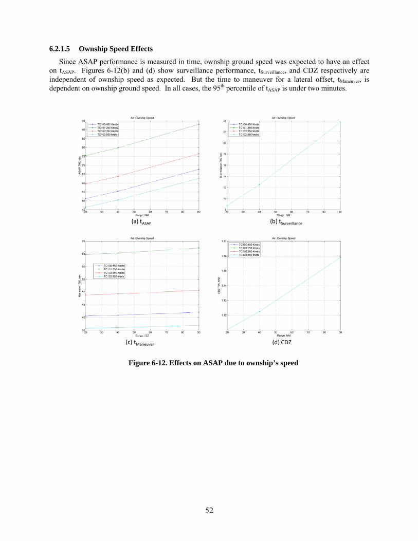
52
6.2.1.5 Ownship Speed Effects
Since ASAP performance is measured in time, ownship ground speed was expected to have an effect on tASAP. Figures 6-12(b) and (d) show surveillance performance, tSurveillance, and CDZ respectively are independent of ownship speed as expected. But the time to maneuver for a lateral offset, tManeuver, is dependent on ownship ground speed. In all cases, the 95th percentile of tASAP is under two minutes.
(a) tASAP (b) tSurveillance
(c) tManeuver (d) CDZ
Figure 6-12. Effects on ASAP due to ownship’s speed
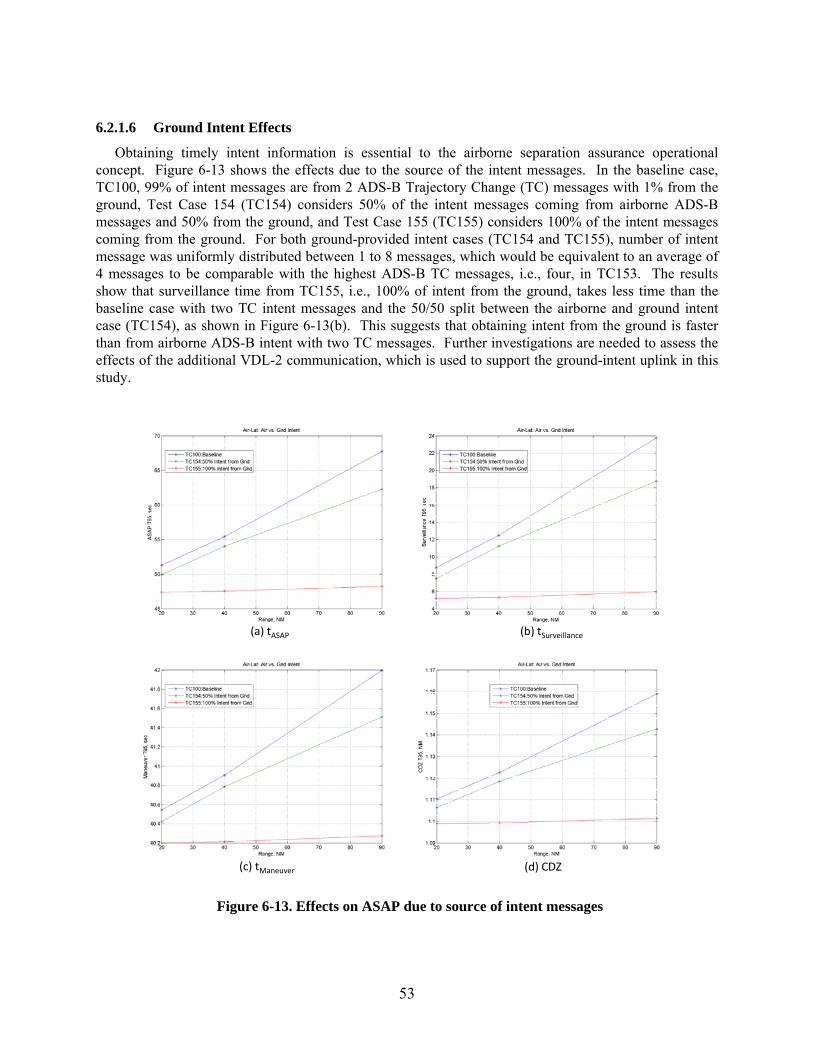
53
6.2.1.6 Ground Intent Effects
Obtaining timely intent information is essential to the airborne separation assurance operational concept. Figure 6-13 shows the effects due to the source of the intent messages. In the baseline case, TC100, 99% of intent messages are from 2 ADS-B Trajectory Change (TC) messages with 1% from the ground, Test Case 154 (TC154) considers 50% of the intent messages coming from airborne ADS-B messages and 50% from the ground, and Test Case 155 (TC155) considers 100% of the intent messages coming from the ground. For both ground-provided intent cases (TC154 and TC155), number of intent message was uniformly distributed between 1 to 8 messages, which would be equivalent to an average of 4 messages to be comparable with the highest ADS-B TC messages, i.e., four, in TC153. The results show that surveillance time from TC155, i.e., 100% of intent from the ground, takes less time than the baseline case with two TC intent messages and the 50/50 split between the airborne and ground intent case (TC154), as shown in Figure 6-13(b). This suggests that obtaining intent from the ground is faster than from airborne ADS-B intent with two TC messages. Further investigations are needed to assess the effects of the additional VDL-2 communication, which is used to support the ground-intent uplink in this study.
(a) tASAP (b) tSurveillance
(c) tManeuver (d) CDZ
Figure 6-13. Effects on ASAP due to source of intent messages
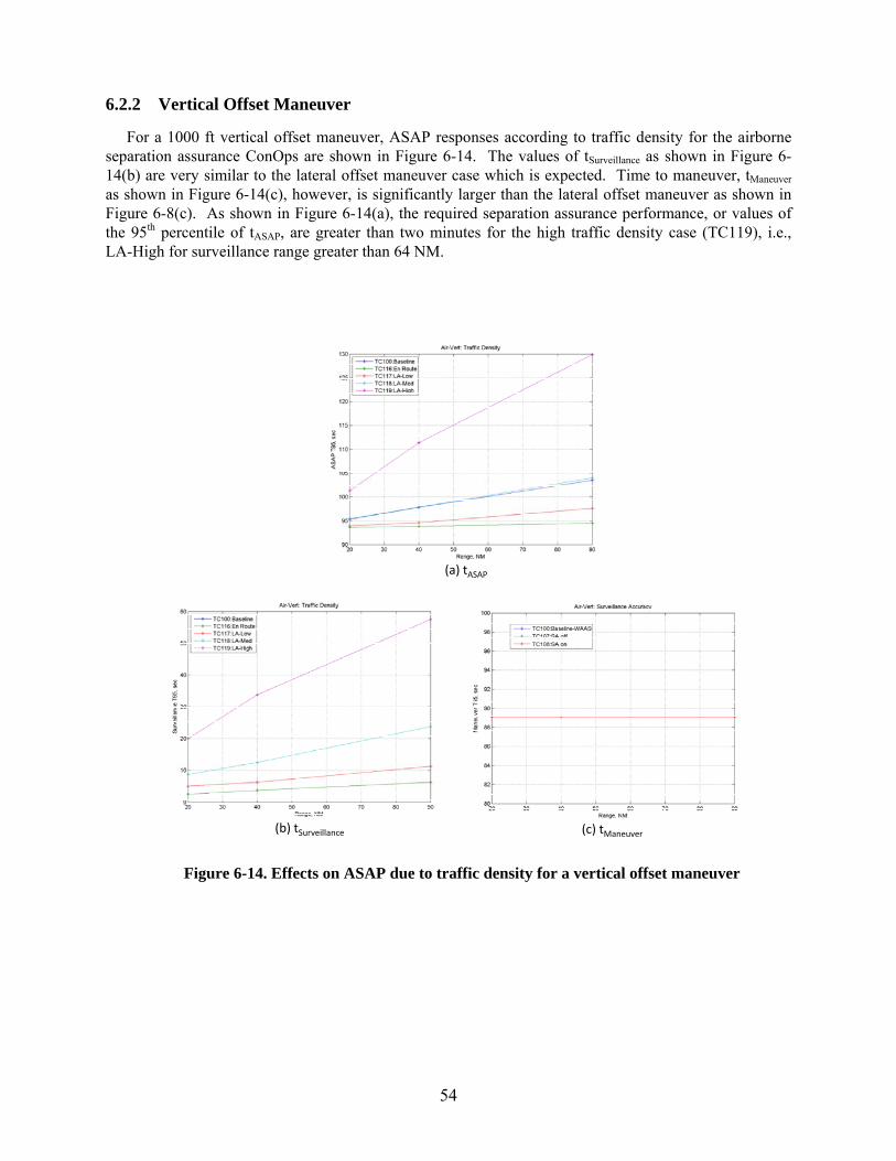
54
6.2.2 Vertical Offset Maneuver
For a 1000 ft vertical offset maneuver, ASAP responses according to traffic density for the airborne separation assurance ConOps are shown in Figure 6-14. The values of tSurveillance as shown in Figure 6-14(b) are very similar to the lateral offset maneuver case which is expected. Time to maneuver, tManeuver as shown in Figure 6-14(c), however, is significantly larger than the lateral offset maneuver as shown in Figure 6-8(c). As shown in Figure 6-14(a), the required separation assurance performance, or values of the 95th percentile of tASAP, are greater than two minutes for the high traffic density case (TC119), i.e., LA-High for surveillance range greater than 64 NM.
(a) tASAP
(b) tSurveillance (c) tManeuver
Figure 6-14. Effects on ASAP due to traffic density for a vertical offset maneuver
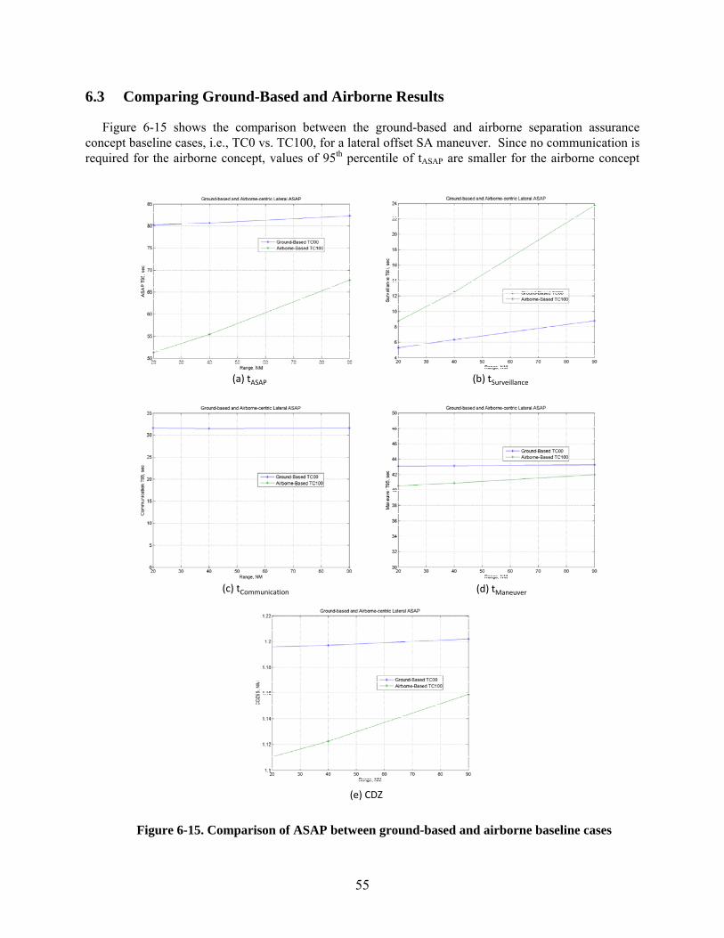
55
6.3 Comparing Ground-Based and Airborne Results
Figure 6-15 shows the comparison between the ground-based and airborne separation assurance concept baseline cases, i.e., TC0 vs. TC100, for a lateral offset SA maneuver. Since no communication is required for the airborne concept, values of 95th percentile of tASAP are smaller for the airborne concept
(a) tASAP (b) tSurveillance
(c) tCommunication (d) tManeuver
(e) CDZ
Figure 6-15. Comparison of ASAP between ground-based and airborne baseline cases
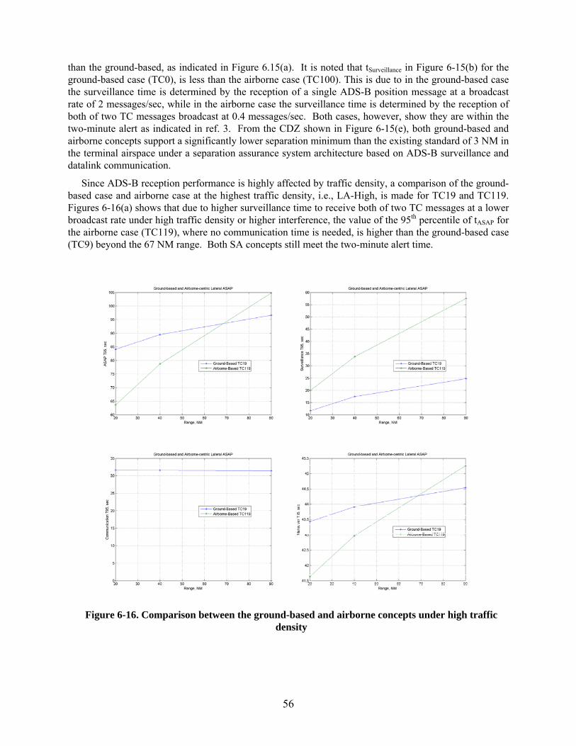
56
than the ground-based, as indicated in Figure 6.15(a). It is noted that tSurveillance in Figure 6-15(b) for the ground-based case (TC0), is less than the airborne case (TC100). This is due to in the ground-based case the surveillance time is determined by the reception of a single ADS-B position message at a broadcast rate of 2 messages/sec, while in the airborne case the surveillance time is determined by the reception of both of two TC messages broadcast at 0.4 messages/sec. Both cases, however, show they are within the two-minute alert as indicated in ref. 3. From the CDZ shown in Figure 6-15(e), both ground-based and airborne concepts support a significantly lower separation minimum than the existing standard of 3 NM in the terminal airspace under a separation assurance system architecture based on ADS-B surveillance and datalink communication.
Since ADS-B reception performance is highly affected by traffic density, a comparison of the ground-based case and airborne case at the highest traffic density, i.e., LA-High, is made for TC19 and TC119. Figures 6-16(a) shows that due to higher surveillance time to receive both of two TC messages at a lower broadcast rate under high traffic density or higher interference, the value of the 95th percentile of tASAP for the airborne case (TC119), where no communication time is needed, is higher than the ground-based case (TC9) beyond the 67 NM range. Both SA concepts still meet the two-minute alert time.
Figure 6-16. Comparison between the ground-based and airborne concepts under high traffic density
57
7 Conclusions
A statistical-based simulation model was developed to investigate required separation assurance performance based on the NextGen technology enablers in surveillance and communication, which are ADS-B and VDL-2 respectively. The simulation framework was constructed following two representative separation assurance system architectures, i.e., ground-based and airborne-centric concepts, with three major elements: surveillance, communication, and flight maneuver. The objective was to develop objective measurements to determine the required separation assurance performance according to specified operational performance metrics, e.g., availability, continuity, and integrity in surveillance and communication subsystems. Additional parameters were also included in the model, such as range, air traffic density, uncertainty and accuracy of surveillance, datalink rate and message length. Off-nominal operational conditions, including falling back to voice for communication and Secondary Surveillance Radar as a backup for surveillance when ADS-B was not available, were also included in the investigation. Human performance responses were modeled based on results from applicable studies, and terrestrial network latencies were adapted from existing specifications.
The following conclusions are developed from the test results.
1) The results support a two-minute alert time as suggested in ref. 3 for an ADS-B based surveillance system architecture and 1 NM buffer zone. The alert time can be reduced to one minute in less congested airspace such as en route airspace.
2) The Collision Detection Zone (CDZ) developed based on surveillance uncertainty and accuracy, which is equivalent to the separation minimum, shows a horizontal separation minimum of less than 2 NM for a GPS-based surveillance system. Under the TRACON SSR case, CDZ is consistent with the current horizontal separation minimum at 3 NM. However, for the Center SSR case, CDZ developed under the methodology in this study is greater than the current horizontal separation minimum of 5 NM.
3) Under the ground-based separation assurance system architecture, required communication time or tCommunication for datalink is significantly less than the voice communication.
4) Under the airborne concept with up to four intent messages, tASAP shows the two-minute alert time is very conservative with the given 1 NM buffer zone.
5) Under the airborne concept, the ground-provided intent via VDL-2 takes less time than the four Trajectory Change messages from the airborne ADS-B link.
6) The airborne concept shows less tASAP than the ground-based separation assurance system architecture as expected since communication on the resolution maneuver is not required under that concept.
7) The vertical offset maneuver in both ground-based and airborne concept of operations shows significant maneuver time increase over the lateral offset maneuver.
58
8 Recommendations
The following recommendations are made to improve the methodology and models developed under this effort.
1. The 1 NM buffer is an arbitrary estimate to account for unexpected events developing during the flight maneuver such as weather or sudden change of the intruder trajectory. This buffer needs to be investigated with human-in-the-loop simulation under different encounter geometries to determine the proper value to be used.
2. The methodology to account for surveillance uncertainty and accuracy needs to be verified to ensure compliance with the existing horizontal separation minimum supported by Center SSR.
3. When intent surveillance information is used in the airborne separation assurance concept under high traffic density, resulted surveillance performance exceeds recommended State Vector report update interval. Further investigations are recommended to determine if new performance requirements are needed for ADS-B applications that require intent information in addition to the State Vector reports.
4. The VDL-2 model does not account for signal degradation due to distance as the ADS-B reception model does. Inclusion of this RF transmission property, i.e., free-space loss, is desired.
5. A literature search should be conducted to document human performance response according to datalink applications under the NextGen environment and to enhance the fidelity of human performance response used in the simulation developed in this study.
6. Several subsystems’ performances were represented by engineering estimates, e.g., human operator lapse due to distraction, ANSPLapse, and processing time at Host and ANSP Workstation. Future studies will be needed to enhance the fidelity of these modeling elements.
7. A human-in-the-loop simulation should be conducted with various encounter geometries to test and verify separation assurance performance for surveillance, communication, and flight maneuver, and the results should be applied to refine the model to support future separation assurance requirement estimates.
59
9 References
1. JPDO: “Concept of Operations for the Next Generation Air Transportation System,” Joint Planning and Development Office, Version 3.2, 30 September 2010.
2. FAA: “FAA’s NextGen Implementation Plan,” Federal Aviation Administration, March 2011.
3. RTCA: “Minimum Aviation System Performance Standards for Automatic Dependent Surveillance Broadcast (ADS-B),” RTCA DO-242A, June 25, 2002.
4. FAA: “Final Program Requirements for Data Communications,” DRAFT, 6 June 2009.
5. Wing, David, et al.: “Comparison of Ground-Based and Airborne Function Allocation Concepts for NextGen Using Human-In-The-Loop Simulations,” 10th AIAA Aviation Technology, Integration, and Operations (ATIO), 13-15 September 2010, Fort Worth, Texas.
6. FAA: “National Airspace System Enterprise Architecture,” National Airspace System Near-Term (2010) As-Is Enterprise-Level Architecture,” Air Traffic Organization, FAA, Version 1.0 January 29, 2010.
7. FAA: “NAS System Specification, Functional and Performance Requirement for the National Airspace System, General, Volume 1,” FAA, Department of Transportation, NAS-SS-1000, 15 April 1995.
8. FAA: “National Airspace System Requirements Specifications,” Department of Transportation, NAS-SR-1000, Revision B, June 2008.
9. FAA: “Air Traffic Control Radar Beacon System (ATCRBS) Characteristics,” FAA Order 1010.51A, 8 March 1971.
10. Santiago, C; and Crowell, A.: “A Visualization Tool for Analysis of Air Traffic Management Scenarios and Automation,” AIAA 2010 Modeling and Simulation Technologies Conference, AIAA-2010-7613, August 2010, Toronto, Canada.
11. FAA: “Fact Sheet – Automatic Dependent Surveillance – Broadcast (ADS-B),” May 27, 2010.
12. RTCA: “Minimum Aviation System Performance Standards for Aircraft Surveillance Applications,” Draft Version 3.0, RTCA SC-186, WG-6-WP27-04, 2011.
13. RTCA: “Minimum Operational Performance Standards (MOPS) for Aircraft Surveillance Applications System (ASAS),” RTCA DO-317, April 14, 2009.
14. RTCA: “Minimum Operational Performance Standards for 1090 MHz Extended Squitter Automatic Dependent Surveillance – Broadcast (ADS-B) and Traffic Information Services – Broadcast (TIS-B),” RTCA DO-260B, December 2, 2009.
15. FAA: “FAA’s NextGen Implementation Plan,” Department of Transportation, March 2011.
16. RTCA: “Minimum Aviation System Performance Standards for Aircraft Surveillance Applications (ASA),” RTCA DO-289, December 2003.
60
17. Mercer, J.; Prevot, T.; Brasil, C.; Mainini, M.; Kupfer, M.; and Smith, N.: “An Integrated Tool Suite for En Route Radar Controllers in NextGen,” 27th International Congress of the Aeronautical Sciences, 2010.
18. SC-186: “Proposed Revisions to ADS-B MASPS: Integrity and Accuracy Monitoring, RTCA Special Committee (SC) 186 WG-6 NIC/NAC Draft 3.0, July 2001.
19. Wing, D, et al.: “Comparison of Ground-Based and Airborne Function Allocation Concepts for NextGen Using Human-In-The-Loop Simulations,” AIAA Aviation Technology, Integration, and Operations Conference, September 2010, Ft. Worth, Texas.
20. Erzberger, H.: “Transforming the NAS: The Next Generation Air Traffic Control System,” NASA TP-2004-212828, October 2004.
21. Chung, W., and Staab, R.: “A 1090 MHz Extended Squitter Automatic Dependent Surveillance – Broadcast (ADS-B) Reception Model for Air-Traffic-Management Simulations,” AIAA AIAA-2006-6614, Keystone, Colorado, August 2006.
22. Bretmersky, S., and Apaza, R.: “Esitmation of VDL Mode 2 with Hidden Transmitters,” 2009 IEEE Aerospace Conference, 978-1-4244-2622-5, Big Sky, Montana, March 2009.
23. RTCA: “Signal-In-Space Minimum Aviation System Performance Standards (MASPS) for Advanced VHF Digital Data Communications include Compatibility with Digital Voice Techniques,” RTCA DO-224B, 2005.
24. Consiglio, M., et al.: “Human In The Loop Simulation Measures of Pilot Response Delay in a Self-Separation Concept of Operations,” 27th International Congress of the Aeronautical Sciences, ICAS 2010, Nice, France, September 2010.
25. Lazito, S., et al.: “The Impact of Voice, Data Link, and Mixed Air Traffic Control Environments on Flight Deck Procedures,” 2003 ATM 5th Seminar, Budapest, Hungary.
26. Sheridan, T., et al.: “Human Transient Into-the-Loop Simulation for NGATS,” AIAA Modeling and Simulation Technologies Conference and Exhibit, AIAA 2006-6114, Keystone, Colorado, August 2006.
27. FAA: “Automatic Dependent Surveillance – Broadcast (ADS-B) Out Performance Requirements to Support Air Traffic Control (ATC) Service; Final Rule,” Part III, 14 CFR Part 91, Department of Transportation, 28 May, 2010.
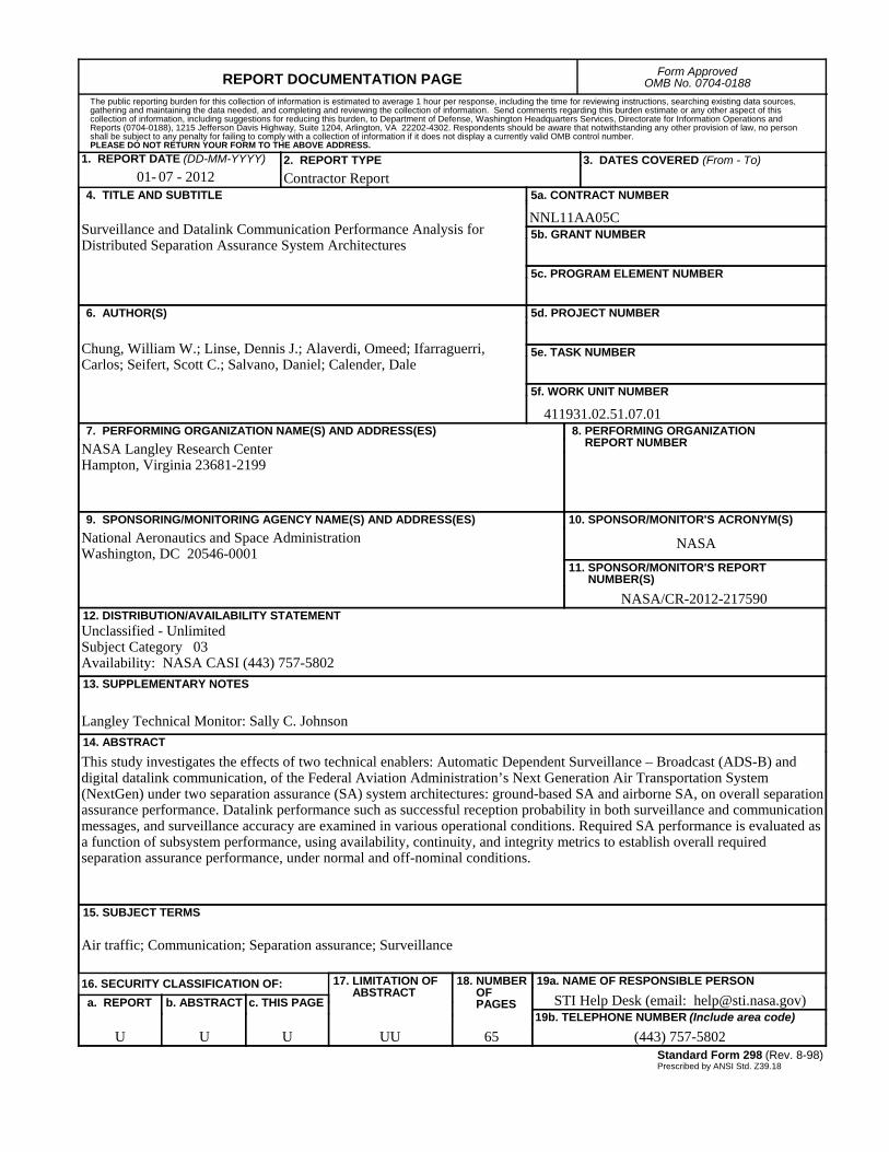
REPORT DOCUMENTATION PAGEForm Approved
OMB No. 0704-0188
2. REPORT TYPE
Contractor Report 4. TITLE AND SUBTITLE
Surveillance and Datalink Communication Performance Analysis for Distributed Separation Assurance System Architectures
5a. CONTRACT NUMBER
NNL11AA05C
6. AUTHOR(S)
Chung, William W.; Linse, Dennis J.; Alaverdi, Omeed; Ifarraguerri, Carlos; Seifert, Scott C.; Salvano, Daniel; Calender, Dale
7. PERFORMING ORGANIZATION NAME(S) AND ADDRESS(ES)
NASA Langley Research Center Hampton, Virginia 23681-2199
9. SPONSORING/MONITORING AGENCY NAME(S) AND ADDRESS(ES)
National Aeronautics and Space AdministrationWashington, DC 20546-0001
8. PERFORMING ORGANIZATION REPORT NUMBER
10. SPONSOR/MONITOR'S ACRONYM(S)
NASA
13. SUPPLEMENTARY NOTES
Langley Technical Monitor: Sally C. Johnson
12. DISTRIBUTION/AVAILABILITY STATEMENTUnclassified - UnlimitedSubject Category 03Availability: NASA CASI (443) 757-5802
19a. NAME OF RESPONSIBLE PERSON
STI Help Desk (email: [email protected])
14. ABSTRACT
This study investigates the effects of two technical enablers: Automatic Dependent Surveillance – Broadcast (ADS-B) and digital datalink communication, of the Federal Aviation Administration’s Next Generation Air Transportation System (NextGen) under two separation assurance (SA) system architectures: ground-based SA and airborne SA, on overall separation assurance performance. Datalink performance such as successful reception probability in both surveillance and communication messages, and surveillance accuracy are examined in various operational conditions. Required SA performance is evaluated as a function of subsystem performance, using availability, continuity, and integrity metrics to establish overall required separation assurance performance, under normal and off-nominal conditions.
15. SUBJECT TERMS
Air traffic; Communication; Separation assurance; Surveillance
18. NUMBER OF PAGES
65
19b. TELEPHONE NUMBER (Include area code)
(443) 757-5802
a. REPORT
U
c. THIS PAGE
U
b. ABSTRACT
U
17. LIMITATION OF ABSTRACT
UU
Prescribed by ANSI Std. Z39.18Standard Form 298 (Rev. 8-98)
3. DATES COVERED (From - To)
5b. GRANT NUMBER
5c. PROGRAM ELEMENT NUMBER
5d. PROJECT NUMBER
5e. TASK NUMBER
5f. WORK UNIT NUMBER
411931.02.51.07.01
11. SPONSOR/MONITOR'S REPORT NUMBER(S)
NASA/CR-2012-217590
16. SECURITY CLASSIFICATION OF:
The public reporting burden for this collection of information is estimated to average 1 hour per response, including the time for reviewing instructions, searching existing data sources, gathering and maintaining the data needed, and completing and reviewing the collection of information. Send comments regarding this burden estimate or any other aspect of this collection of information, including suggestions for reducing this burden, to Department of Defense, Washington Headquarters Services, Directorate for Information Operations and Reports (0704-0188), 1215 Jefferson Davis Highway, Suite 1204, Arlington, VA 22202-4302. Respondents should be aware that notwithstanding any other provision of law, no person shall be subject to any penalty for failing to comply with a collection of information if it does not display a currently valid OMB control number.PLEASE DO NOT RETURN YOUR FORM TO THE ABOVE ADDRESS.
1. REPORT DATE (DD-MM-YYYY)
07 - 201201-