SURGICAL TECHNIQUE - Zimmer Biomet Wide side Cables All cables are made with a7 x 7 construction....
16
B B M M P P ™ ™ C C A A B B L L E E S S Y Y S S T T E E M M S S U U R R G G I I C C A A L L T T E E C C H H N N I I Q Q U U E E
Transcript of SURGICAL TECHNIQUE - Zimmer Biomet Wide side Cables All cables are made with a7 x 7 construction....
BBBB MMMM PPPP ™™™™
CCCCAAAABBBBLLLLEEEESSSS YYYY SSSS TTTT EEEE MMMM
SSSS UUUU RRRR GGGG IIII CCCC AAAA LLLL
TTTT EEEE CCCC HHHH NNNN IIII QQQQ UUUU EEEE

Biomet, as the manufacturer of thisdevice, does not practice medicine anddoes not recommend these or any othersurgical techniques for use on a specificpatient. The surgeon who performs anyprocedure is responsible for determiningand utilizing the appropriate technique forsuch procedure for each individualpatient. Biomet is not responsible forselection of the appropriate surgicaltechnique to be utilized for an individualpatient.
1. Treharne, Sander, Oh. “The FatigueResistance of Stainless Steel Wire inVarious Iatrogenic Conditions”.Transactions of the Orthopaedic ResearchSociety. Jan. 1982 p. 346.2. Clarke, Shea, Brerbaum. “TrochantericOsteotomy - Analysis of Pattern of WireFixation, Failure and Complications”.CORR 1979. 141:102-10.
The Biomet Medical Products(BMP™) Cable System provides acost effective and simple methodof trochanteric reattachment,fracture fixation, and cerclagecabling. Our system featurescable implants based upon a clin-ically proven design concept andinstrumentation that is a vastimprovement over competitivecable systems. Our innovativecable plates offer both a techno-logical and economic advantagethat is exclusive to the BMPCable System.
IIIINNNNTTTTRRRROOOODDDDUUUUCCCCTTTT IIIIOOOONNNN
Cerclage Cable Vs. Monofilament WireThe use of monofilament wire forcerclage wiring and trochantericreattachment is a well estab-lished practice. Typically, a1.0mm or 1.2mm monofilamentstainless steel wire is used inconjunction with a wire twistinginstrument. This practice is notwithout complications. Failure ofmonofilament wire can occur asa result of metal fatigue at thesite of small surface defects or“notches” in the wire.
Testing has shown that a notchor scratch only .06mm or twothousandths of an inch deep in a 1.2mm wire can reduce itsfatigue strength by 78%.1Clinical results of monofilamentwire used for reattachment ofthe greater trochanter show aloss of trochanteric positionranging from 2.7% to 19.4%and an incidence of wire break-age ranging from 17.2% to26.5%.2*
Clearly the need for a cerclagematerial that is stronger andmore durable than monofilamentwire has been established.Multistrand cable, with its supe-rior mechanical properties andversatility, has proven to be thesolution.
1
CCCCLLLL IIIINNNNIIIICCCCAAAALLLL IIIINNNNDDDDIIIICCCCAAAATTTT IIIIOOOONNNNSSSS
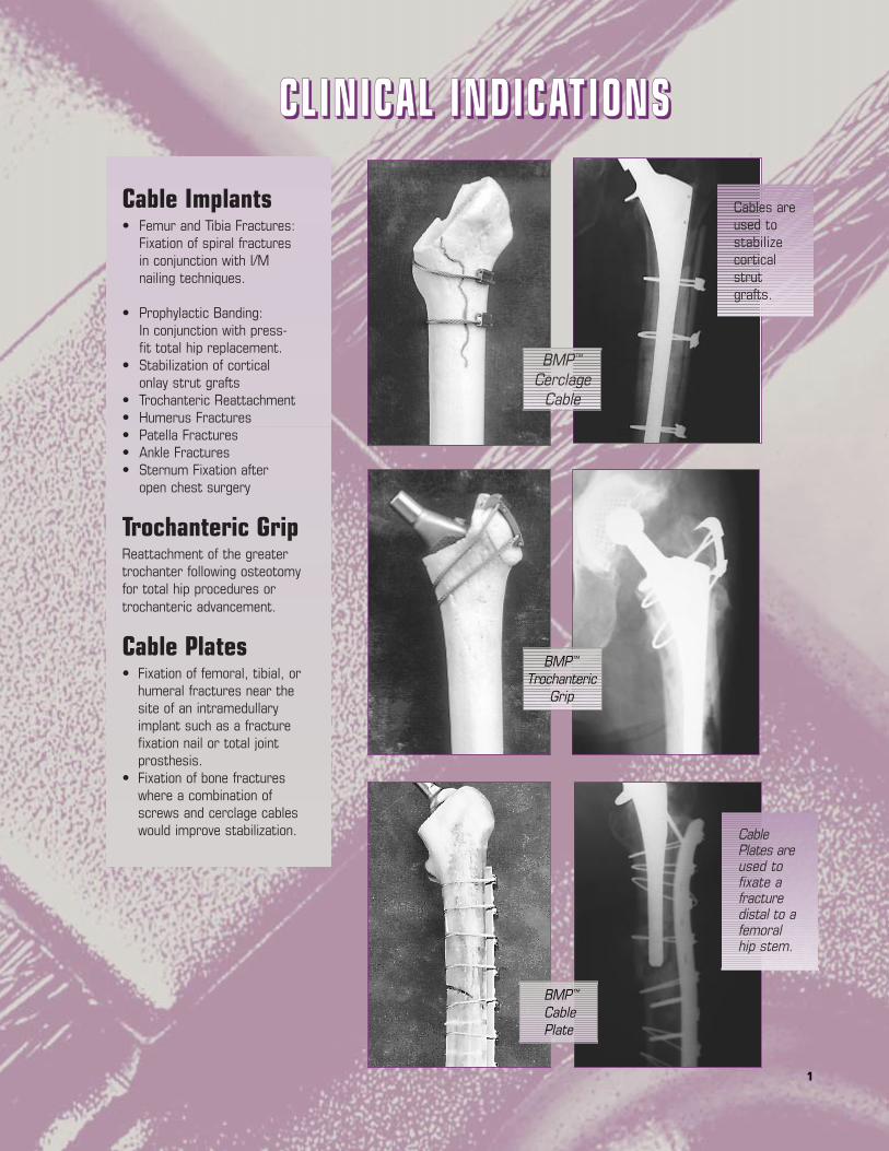
BMP™
CerclageCable
BMP™
TrochantericGrip
BMP™
CablePlate
Cables areused tostabilizecorticalstrutgrafts.
CablePlates areused tofixate afracturedistal to afemoralhip stem.
Cable Implants• Femur and Tibia Fractures:
Fixation of spiral fractures in conjunction with I/M nailing techniques.
• Prophylactic Banding:In conjunction with press-fit total hip replacement.
• Stabilization of cortical onlay strut grafts
• Trochanteric Reattachment• Humerus Fractures• Patella Fractures• Ankle Fractures• Sternum Fixation after
open chest surgery
Trochanteric GripReattachment of the greatertrochanter following osteotomyfor total hip procedures ortrochanteric advancement.
Cable Plates• Fixation of femoral, tibial, or
humeral fractures near the site of an intramedullary implant such as a fracture fixation nail or total joint prosthesis.
• Fixation of bone fractures where a combination of screws and cerclage cables would improve stabilization.

2
Wide side
CablesAll cables are made with a 7 x 7construction. Seven individualwires form a bundle and sevenbundles are combined to formeach cable. This constructionwas chosen to optimize a com-bination of cable strength andflexibility [Figure 1].
Cobalt Chrome (2.0mm and1.6mm diameters) – The CoCrcables are for use in the vicinityof any CoCr or Titanium implant.The 2.0mm CoCr cable is alsoused in conjunction with theCoCr trochanteric grip.
Stainless Steel (2.0mm only) –The stainless steel cables are foruse in the vicinity of any stain-less steel implant and in conjunc-tion with the BMP Cable Plate.
Either material can be used inapplications where no implant ispresent. The CoCr cable implanthas a breaking strength slightlygreater than the stainless steelimplant.
2.0mm diameter cables are themost commonly used size andare most appropriate for use onthe femur where the highestloads can be seen.
1.6mm diameter cables aremost commonly used whengreater flexibility of the cable isrequired to bend around smallerdiameter bones.
All cables are a generous750mm in length to accommo-date numerous applications[Figure 2].
Cable SleevesThree sleeves are available [Figure 3]:
2.0mm CoCr1.6mm CoCr2.0mm Stainless Steel
IMPORTANT: Sleeves are size andmaterial specific. 2.0mm sleevesshould only be used with 2.0mmcable of the same material.1.6mm CoCr sleeves should onlybe used with 1.6mm CoCr cable!
AssemblyAs the sleeve is crimped ontothe cable, the sides of the sleeveare pressed in towards thecable, as shown in [Figure 5]. Allcable sleeves must be installedwith the correct side facing thesurgeon to enable proper crimp-ing of the sleeves. Notice thatthe side of the sleeve facing thesurgeon must be wider than theside of the sleeve facing thebone. This wider side also hasthe etched information on it[Figures 4 & 5].
WARNING: Failure to install thesleeve with the wide side facingthe surgeon could result in theinability to completely crimpthe sleeve.
REMEMBER: WIDE SIDE UP /ETCHED SIDE UP
Figure 1
Figure 2
Figure 3
Figure 4
Figure 5
BBBBMMMMPPPP CCCCAAAABBBBLLLLEEEE
SSSSYYYYSSSSTTTTEEEEMMMM
IIIIMMMMPPPPLLLLAAAANNNNTTTTSSSS

3
This one piece construction elimi-nates the possibility of motionbetween the sleeve and the platethat occurs as a result of cablestretch or plate flexing [Figure 8].This is a significant advantageover the traditional cable plates.This one piece construction alsoeliminates the need to purchaseadditional crimping sleeves whenutilizing a cable plate, providing asignificant cost savings.
Compression Screw Holes – Eachplate features screw holesdesigned to give the surgeon theoption of creating compressionacross the fracture site. Screwsare inserted eccentrically throughthe oval hole as far from thefracture as possible. Thisresults in axial compression ofthe fracture.
The screw holes match up withthe head of most standard4.5mm stainless steel corticalbone screw designs and allowangulation of the screws in anydirection. The center hole in eachplate is “neutral” and does notcreate fracture compression.
Stainless Steel Cables – NOTE: The BMP Cable Plate canbe used in conjunction with onlythe 2.0mm stainless steel cable.
Cable PlateTemplatesFive corresponding cable platetemplates are available (Figure 9).The anodized aluminum tem-plates are etched to indicatecrimp and screw hole locations.
310mm
260mm
210mm
160mm
110mm
ConnectingBar
ProximalHooks
CrimpLocations
DistalSpikes
Traditional
Biomet Design
Figure 6
Figure 7
Figure 8
Figure 9*U.S. Patent No. 5,607,430
Cable Plate Cross Section
Trochanteric GripThe BMP Trochanteric Grip ismade of high strength castcobalt chrome and is available intwo sizes. Each Trochanteric Gripis used with a pair of the 2.0mmCoCr cables and does notrequire any additional cablesleeves [Figure 6].
Two Crimp Locations – Eachcable is looped through one ofthe proximal or distal crimp loca-tions. The crimping areas on theTrochanteric Grip can be com-pressed using the standardsleeve crimping tool.
Proximal Hooks – The proximalhooks reach over the top edge ofthe greater trochanter and resistthe pull of the abductor forces.
Distal Spikes – The distal spikesare embedded in the lateralsurface of the greater trochanterand provide rotational stabilityto the construct.
Connecting Bar – A singleconnecting bar, contoured tothe curvature of the greatertrochanter, maintains the struc-tural integrity of the device.
Cable Plates*
Five lengths of cable plates arecurrently available and made ofhigh strength 316 L stainlesssteel [Figure 7]. The 5mm platethickness provides substantialsupport to the fracture site[Figure 8].
One Piece Construction – TheBMP Cable Plate is the first tooffer crimping sleeves machinedas an integral part of the plate.

44
Figure 10
Figure 11
Guide Pulley
Nar
row
Wid
th
Guide Pulley
Cam Lock
Cam LockBar
Pivot
Cam LockT-Handle
The installation process for anycable component tends to be alabor intensive process. Ourinstruments were designed withthe goal of making this processas hassle free as possible. Theinstrumentation is designed toaddress the needs of the sur-geon for a precise, reproducible,yet fast installation of the com-ponents. Several of these designfeatures set our system apartfrom the competition.
Tensioner DesignFeatures1. Self-Centering Cam Locks :The cam lock bar on each ten-sioner is allowed to pivot aboutits center point [Figure 10]. Thismeans that the crimp sleeve caneasily be centered between theguide pulleys by pivoting the camlock bar with the surgeon’s free hand. Competitive tensionerstend to bind when the crimpsleeve touches a guide pulley.
2. Narrow Guide Pulley Width :The self-centering featureenables us to keep the width ofthe guide pulley assembly to aminimum [Figure 11]. This allowseasier access to the cableimplants while tensioning intight places.
Figure 12
Figure 13
IIIINNNNSSSSTTTTRRRRUUUUMMMMEEEENNNNTTTTAAAATTTT IIIIOOOONNNN
T-Handle Tensioner(#498007) The threaded T-handle design[Figure 11] enables the surgeon totension the cable up to the actualbreaking strength of the cable!This is the ultimate in tensioningcapability. The surgeon tightensthe cable by repeatedly turning theT-handle in a clockwise direction.
Crimper (#498003)This single Crimper is all that isneeded to precisely and repeat-edly crimp all of the BMP CableSleeves, Trochanteric Grip crimplocations,and Cable Plate crimplocations [Figure 12] .
• 20 to 1 mechanical advantage means easy one-hand operation.
• Ratchet Mechanism: pre-vents “under crimping” of the sleeves by not allowing the crimper to release from the sleeve until a minimum crimping level is achieved by the surgeon.
• Dead Stop Mechanism: The crimper hits a dead stop inside the linkage which prevents the surgeon from “over crimping” the sleeves. Some competitive crimpers allow over crimping ofthe sleeves which could cause sleeve damage or notching of the cable. This could result in the loss of cable tension or early failure of the assembly.
• These two features combine to ensure that every cable sleeve is crimped precisely and consistently.

55
Manipulator/Impactor(#498011) The Manipulator/Impactor firmlyclamps onto the TrochantericGrip to aid in the positioning andinsertion of the implant [Figure 17].The device enables the surgeonto use the trochanteric griphooks to pull the trochantericfragment down into positionagainst the abductor tensionwhile tightening the cables.
The Manipulator/Impactor alsoclamps onto the crimp sleevesof the cable plate. This aids thesurgeon when positioning theplate on the bone, reducing thebone fragments, and installingcables or screws.
Instrument Cases(#592038)
The #592038 case accommo-dates two of the T-HandleTensioners and all other cableinstruments [Figure18]. Thecase will accommodate eitherthe impactor or the manipula-tor/impactor but not bothsimultaneously.
Figure 15
Figure 16
Figure 18
Figure 17
Figure 14
Cable Passers(Small #498009/ Large #498008)Two sizes of Cable Passers areavailable to correspond with thediameter of bone that you arecabling. Each passer is a simple,one-piece construction withnothing to assemble or disas-semble. Both passers work withall cable sizes [Figure 13].
Cable Cutter(#498010)The BMP Cable Cutter works ona principle of “offsetting circles”to effortlessly shear the cable,producing a cleanly cut, fraylessend [Figure 14]. The design allowsthe surgeon to cut the cablemuch closer to the edge of thecrimp sleeve than most competi-tive instruments [Figure 15].Just a single cutter required tocut both 1.6mm and 2.0mmdiameter cables.CAUTION: This cutter is designedto cut cables only. Do notattempt to cut pins or wires!
ImpactorsTwo Trochanteric Grip Impactorsare available to suit the surgeon’s preference.
StandardTrochanteric GripImpactor (#498006)The Grip Impactor is used forsimple impaction of the grip intothe greater trochanter [Figure 16].The plastic impact surface pre-vents damage to the implant andespecially the crimp locationsduring impaction.

6Figure 23
Cam LockBar
T-Handle
Cam Lock
Cam Lock
BIOMET
120005Lot N
o.
IMPORTANT: Cable sleeve wide sideup/etched side up.
1111.... Passing the Cable
Hook one of the two CablePassers around the bone(#498008 or #498009). Nextfeed the cable into the hole near-est the handle of the Passer untilthe cable completely surroundsthe bone. Remove the CablePasser while leaving the cable inplace [Figure 20].
2222 .... Sleeve Positioning
Insert each end of the cablethrough the holes in the sleevefrom opposite directions.
It is imperative that the narrowside of the sleeve be against thebone and the wider, etched sideface the surgeon [Figure 20]. Thispositioning enables the crimperto properly engage the sleeve.[Figure 21 & Figure 22]
3333 .... Cable Tensioning
Option B. T-Handle Tensioner(#498007) [Figure 23]. Preparethe tensioner for operation byfirst positioning the cam lockmechanism down near the guidepulleys by turning the T-Handlecounterclockwise.
Next, hook each end of the cablearound the guide wheels andback through the automatic camlocks.
Pull on each cable end to remove any slack.
Figure 19
Figure 20
Figure 22
Figure 21
CCCCAAAABBBBLLLLEEEE ////
SSSSLLLLEEEEEEEEVVVVEEEE
CCCCEEEERRRRCCCCLLLLAAAAGGGGEEEE
TTTTEEEECCCCHHHHNNNNIIIIQQQQUUUUEEEE
7
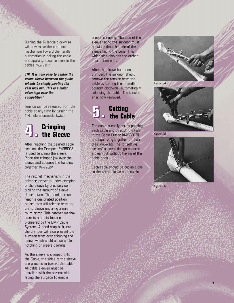
proper crimping. The side of thesleeve facing the surgeon mustbe wider than the side of thesleeve facing the bone. Thiswider side also has the etchedinformation on it.
After the sleeve has beencrimped, the surgeon shouldremove the tension from thecable by turning the T-handlecounter clockwise, automaticallyreleasing the cable. The tension-er is now removed.
5555 .... Cutting the Cable
The cable is easily cut by passingeach cable end through the holein the Cable Cutter (#498010)and squeezing together the han-dles [Figure 26]. The “offsettingcircles” concept design ensuresa clean cut without fraying of thecable ends.
Each cable should be cut as closeto the crimp sleeve as possible.
Figure 24
Figure 25
Figure 26
Turning the T-Handle clockwisewill now move the cam lockmechanism toward the handleautomatically locking the cableand applying equal tension to thecables [Figure 24].
TIP: It is now easy to center thecrimp sleeve between the guidewheels by simply pivoting thecam lock bar. This is a majoradvantage over the competition!
Tension can be released from thecable at any time by turning theT-Handle counterclockwise.
4444 .... Crimping the Sleeve
After reaching the desired cabletension, the Crimper (#498003)is used to crimp the sleeve.Place the crimper jaw over thesleeve and squeeze the handlestogether [Figure 25].
The ratchet mechanism in thecrimper, prevents under crimpingof the sleeve by precisely con-trolling the amount of sleevedeformation. The handles mustreach a designated positionbefore they will release from thecrimp sleeve ensuring a mini-mum crimp. This ratchet mecha-nism is a safety featurepioneered by the BMP CableSystem. A dead stop built intothe crimper will also prevent thesurgeon from over crimping thesleeve which could cause cablenotching or sleeve damage.
As the sleeve is crimped ontothe Cable, the sides of the sleeveare pressed in toward the cable.All cable sleeves must beinstalled with the correct sidefacing the surgeon to enable

88
• Trochanteric Grip with cablesrouted around a cementedstem [Figure 27].
• Trochanteric Grip with cablesrouted through the anteriorand posterior cortices lateralto the stem [Figure 28].
• Trochanteric Grip with cablesrouted medially through thelesser trochanter, femoralneck, or allograft [Figure 29].
Although many options are avail-able, the goal for each is the same.
The osteotomy surfaces are veryrough and cancellous in nature.The goal of all the techniques isto provide compressive forcesbetween these rough surfacesand thereby increase the fric-tional resistance to the superiorshearing forces. This increasesthe strength and rigidity of thefixation. By routing the cables ina proximal lateral to distal medi-al direction, part of the abductormuscle forces are also counter-acted by the tension in thecables.
Surgical indications will dictatewhich cable routing is mostappropriate for each specificcase. The following surgicaltechnique will focus on the stepstaken to reduce the greatertrochanter and secure thetrochanteric grip into place. It isindependent of the method ofcable routing chosen. The CablePassers (#498008 and#498009) can be utilized tofacilitate the passing of thecables around the femur.
Figure 27
Figure 28
Figure 29
Trochanteric Gripwith cables routedaround a cementedstem
Trochanteric Gripwith cables routedmedially through thelesser trochanter,femoral neck, orallograft
Trochanteric Gripwith cables routedthrough the ante-rior and posteriorcortices lateral to the stem
TTTTRRRROOOOCCCCHHHHAAAANNNNTTTTEEEERRRRIIIICCCC
GGGGRRRRIIIIPPPP
SSSSUUUURRRRGGGGIIIICCCCAAAALLLL
TTTTEEEECCCCHHHHNNNNIIIIQQQQUUUUEEEEOsteotomy of the greatertrochanter is often performed fortechnically difficult reconstruc-tions of the proximal femur, revision,and sometimes primary total hipreplacement. It can also be usedduring trochanteric advancementprocedures such as a slidingtrochanteric osteotomy. TheBMP trochanteric grip offers thesurgeon a proven and effectivemeans to stabilize thetrochanteric bone fragment andthus aid in the bony union.
Several patterns of cable rout-ings have been used by sur-geons to resist the abductorforces and securely reattachthe greater trochanter. Some ofthese options are shown at right:

99
tioned through the abductormuscle insertions and over theproximal edge of the trochantericfragment. NOTE: The proximalhooks must pass through theabductor muscle insertions asclose to the bone as possible. The excess cable slack should betaken up by hand as the implant is moved into position.
3333 .... Initial Seatingof the Trochanteric Grip
The grip is then embedded intothe trochanteric fragment byimpacting lightly on theManipulator/Impactor [Figure 32].The plastic surface of the instru-ment prevents damage to theimplant. The goal is to engagethe distal spikes into thetrochanteric fragment and thusprovide rotational stability to theconstruction.
4444 .... and FinalPositioning
Two Cable Tensioners should beused simultaneously to tensionboth the proximal and distalcables [Figure 33]. The CableTensioners are installed on thecables and the cables aresecured into the cam lock mech-anism of the tensioner. Pull oneach cable end to remove anyslack. The cam lock bar can bepivoted to center the trochantericgrip between the guide pulleys.Turn the T-handle clockwise totension the cable. If the surgeon stillrequires the Manipulator/Impactorin place, a tensioner should bepositioned on either side of thehandle as shown.
Figure 30
Figure 31
Figure 32
Figure 33
Cable Tensioning
1111 .... Reducing theTrochanteric Fragment
Reduction is facilitated by holdingthe femur in a slightly flexed,internally rotated, and abductedposition. The trochanteric frag-ment can then be reduced bypulling it into the desired positionusing standard bone reductionforceps or a common bone hook.The trochanteric grip mountedonto the Manipulator/Impactor(#498011) [Figure 30] can also beused to reduce the trochantericfragment.
The surgeon also has the optionof “advancing” the greatertrochanter at this time. This is done by replacing thetrochanteric fragment in a moredistal position to tighten theabductor muscles and increasethe abductor lever arm.
2222 .... Introducingthe TrochantericGrip
The Trochanteric Grip implantcan be securely attached to theManipulator/Impactor(#498011) by tightening theknob [Figure 31]. This assemblythen becomes an excellentinstrument to hook the proximaledge of the trochanteric frag-ment and aid in the positioning of the fragment on the femur.
The cables are most easily routedthrough the Trochanteric Gripprior to positioning the grip ontothe bone. The proximal hooks ofthe Trochanteric Grip are posi-

10
An assistant can now handle thetensioner as the surgeon manip-ulates the trochanteric fragmentinto its final position. This can beaccomplished with a variety ofinstruments including theManipulator/Impactor or a common bone hook passed overthe top of the greater trochanter.While the desired position isbeing maintained, the cables canbe tightened by using the ten-sioners and secure theTrochanteric Grip in place. TheManipulator/Impactor may beremoved if the desired stabiliza-tion is achieved.
5555 .... Final Seating and Cable Tensioning
Verify that the proximal hookshave properly engaged in theproximal edge of the trochanter.Sometimes hard bone can pre-vent firm engagement of thehooks. The grip is now fully seatedwith an Impactor (#498006 or#498011) [Figure 34]. Theimpacting should always be in adistal direction to prevent thetrochanteric fragment from slip-ping proximally during impaction.
The cables are now fully ten-sioned and any slack created bythe Impactor is eliminated.
The firm fixation of thetrochanter can be verified bymanipulation of the femur whilepalpating and visually inspectingfor any movement between thetrochanteric fragment and thefemur. If the position or fixationof the trochanter is not satisfac-tory, repeat the tensioning andfinal seating process.
Figure 34
Figure 36
Figure 35
6666 .... Crimping of theTrochanteric Grip to the Cables
The Trochanteric Grip can now becrimped using the Crimper(#498003) [Figure 35). NOTE: No cable sleeves arerequired! The crimping section ofthe trochanteric grip acts as thecrimping sleeve. The area can becrimped twice to utilize the entirewidth of the crimp area for maxi-mum holding power.
7777 .... Cutting the Cable Ends
The free ends of the cable cannow be easily cut by passingeach end through the hole in theCable Cutter (#498010) [Figure 36]
and squeezing together thehandles. Each cable should becut as close to the trochantericgrip as possible.
11
BMP™ is a trademark of Biomet,Inc. Warsaw, IN
Tension Load
Tension Load
Load
Sleeve
1" Diameter
Load
MMMMEEEECCCCHHHHAAAANNNNIIIICCCCAAAALLLL
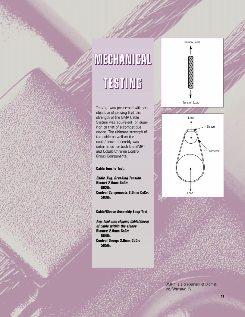
TTTTEEEESSSSTTTT IIIINNNNGGGGTesting was performed with theobjective of proving that thestrength of the BMP CableSystem was equivalent, or supe-rior, to that of a competitivedevice. The ultimate strength ofthe cable as well as thecable/sleeve assembly wasdetermined for both the BMPand Cobalt Chrome ControlGroup Components.
Cable Tensile Test:
Cable Avg. Breaking TensionBiomet 2.0mm CoCr:
602lb.Control Components 2.0mm CoCr:
583lb.
Cable/Sleeve Assembly Loop Test:
Avg. load until slipping Cable/Sleeveof cable within the sleeveBiomet: 2.0mm CoCr:
584lb.Control Group: 2.0mm CoCr:
505lb.
12
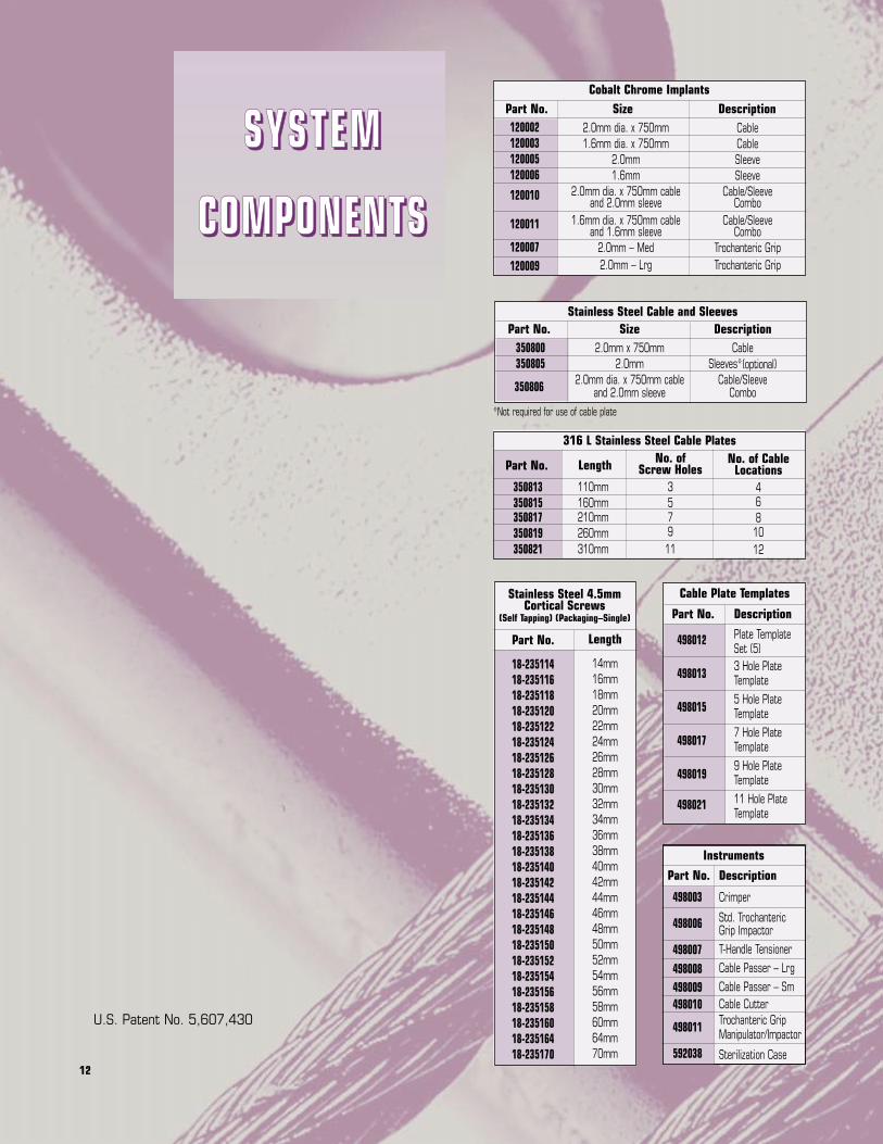
U.S. Patent No. 5,607,430
Instruments
Stainless Steel 4.5mmCortical Screws
(Self Tapping) (Packaging–Single)
Length
14mm16mm18mm20mm22mm24mm26mm28mm30mm32mm34mm36mm38mm40mm42mm44mm46mm48mm50mm52mm54mm56mm58mm60mm64mm70mm
Stainless Steel Cable and SleevesSize
2.0mm x 750mm2.0mm
2.0mm dia. x 750mm cable and 2.0mm sleeve
DescriptionCable
Sleeves*(optional)Cable/Sleeve
Combo
Part No.
498003
498006
498007498008498009498010
498011
592038
Part No.
18-23511418-23511618-23511818-23512018-23512218-23512418-23512618-23512818-23513018-23513218-23513418-23513618-23513818-23514018-23514218-23514418-23514618-23514818-23515018-23515218-23515418-23515618-23515818-23516018-23516418-235170
Cable Plate Templates
Description
Plate Template Set (5)3 Hole PlateTemplate5 Hole PlateTemplate7 Hole PlateTemplate9 Hole PlateTemplate11 Hole PlateTemplate
Part No.
498012
498013
498015
498017
498019
498021
316 L Stainless Steel Cable Plates
Length
110mm160mm210mm260mm310mm
No. of Screw Holes
357911
No. of CableLocations
468
1012
Part No.
350813350815350817350819350821
Cobalt Chrome Implants
2.0mm dia. x 750mm1.6mm dia. x 750mm
2.0mm1.6mm
2.0mm dia. x 750mm cable and 2.0mm sleeve
1.6mm dia. x 750mm cable and 1.6mm sleeve
2.0mm – Med2.0mm – Lrg
CableCableSleeveSleeve
Cable/Sleeve Combo
Cable/Sleeve Combo
Trochanteric GripTrochanteric Grip
Part No. Size Description120002120003120005120006
120010
120011
120007120009
Part No.350800350805
350806
*Not required for use of cable plate
Description
Crimper
Std. Trochanteric Grip ImpactorT-Handle TensionerCable Passer – LrgCable Passer – SmCable CutterTrochanteric GripManipulator/Impactor
Sterilization Case
SSSS YYYY SSSS TTTT EEEE MMMM
CCCCOOOOMMMMPPPPOOOONNNNEEEENNNNTTTTSSSS

13

P.O. Box 587• Warsaw, Indiana 46581-0587 • (219) 267-6639 ©1998 Biomet, Inc. All Rights Reservedweb site: http://www.biomet.com • eMail: [email protected]
Form No. Y-BMT540/051598/K