Surgical Technique Pyramid Hip Cup - Atesosatesos.ch/wp-content/uploads/2016/07/Surgical... ·...
17
Atesos medical AG, Schachenallee 29, CH-5000 Aarau Edition: 07/16-EN Surgical Technique Pyramid Hip Cup Uncemented Hip Cup System Atesos medical AG 5000 Aarau Switzerland
-
Upload
truongthuy -
Category
Documents
-
view
223 -
download
1
Transcript of Surgical Technique Pyramid Hip Cup - Atesosatesos.ch/wp-content/uploads/2016/07/Surgical... ·...
Atesos medical AG, Schachenallee 29, CH-5000 Aarau
Edition: 07/16-EN
Surgical Technique Pyramid Hip Cup
Uncemented Hip Cup System
Atesos medical AG
5000 Aarau
Switzerland

Surgical Technique Pyramid Hip Cup
Atesos medical AG, Schachenallee 29, CH-5000 Aarau
Lit.No.: 501.D001-D5 page 2/17
Surgical Technique Pyramid Hip Cup
Product description:
The Pyramid acetabular system allows for excellent primary stability without excessive seating forces due to the
unique unidirectional macrostructure surface. The metal shell is made of a Ti6Al4V alloy and has a constant press
fit ratio between reaming and oversize for all diameters and is flattened in the pole –region.
The Pyramid Cup is offered in 2 different coated types: a double coated version, made of a Ti-Plasma sprayed
coating of thickness 0.2mm and a thin layer CaP of thickness 20µm which serves for accelerated osseointegration
and is fully absorbed.
The single coated version is covered with this CaP layer only, underneath there is a macro structure* overlaid by
a roughness of approx.. 6-8 µm produced by grit blasting.
Only the double coated version is delivered in sizes 46-68 (70) in a type with optional cancellous bone screw
fixation and for revision cases. When delivered, the screw holes are closed.
The threaded hole in the pole is sealed by a screw after implantation.
* Patent pending
Chart 1a+1b display the disposable articulating inlays.
Ceramic inlays for the head sizes 28, 32, 36 mm are available. The ceramic system provides the largest head
diameter for the given shell--used. Standard Polyethylene inlays are available for the head sizes 28mm (shell 42-
48 mm) and 32 mm (shell 50-62 mm). Inlays made of x-linked Polyethylene are offered for the largest possible
head diameter (28 – 32 – 36 mm) for respective shell size. From cup size 50, head size 32 or 36 can be chosen.
articulating inlays
Primary shell
(w.out screw holes)
Polyethylene x-linked Pe Ceramic*
42 - 44 28 28 28
46 - 48 28 32 32
50 - 52 32 32 36 36
54 - 56 32 32 36 36
58 - 62 32 32 36 36
Chart 1a: Head diameters and inlays for primary shell
articulating inlays
Revision shell
(3-holes)
Polyethylene x-linked Pe Ceramic*
46 - 50 28 32 32
52 - 56 32 32 36 36
58 - 60 32 32 36 36
62 – 68 (70) 32 32 36 36
Chart 1b: Head diameters and inlays for revision shell
* Biolox Delta-Inserts, Manufacturer CeramTec GmbH Medical Products Division or ELEC®plus -Inserts, Manufacturer HiPer MEDICAL AG

Surgical Technique Pyramid Hip Cup
Atesos medical AG, Schachenallee 29, CH-5000 Aarau
Lit.No.: 501.D001-D5 page 3/17
The instrumentation is adaptable to any surgical approach. In addition to standard tools offset instruments for
MIS incisions are offered. Its design focuses on easy and safe handling and universal use, including the femur
first technique.
Indications: Primary and secondary arthritis of the hip; fracture of the femoral neck, avascular necrosis of the femoral head, rheumatoid arthritis in case of sufficient bone quality. For revision products: revision interventions up to max. Paproxky 2b.
Contraindications:
Extensive deformations and defects of the acetabulum, radiographic manifest osteoporosis or osteomalcia,
progressive tumour diseases local and generalized, radiation compromised bone stock, acute infection of the
joint or the environment, persistent or potential infectious diseases with influence on the joint; muscular nerve or
vessel disease which may threaten the extremity, pregnancy.
Surgical incisions:
The implant system and the associated instruments permit the implantation by all established incisions like the
lateral transgluteal incision according to Bauer, the antero- lateral incision according to Watson Jones, the
posterior incision and the anterior incision according to Smith Peterson including the minimally invasive versions.
Warning Indications & Symbols:
Manufacturer
Read instruction for use
Single use only!
Expiration date year / month
Do not use if the packaging is damaged or the seal is broken.
Sterilized by gamma radiation in the final packaging
Sterilized by EO in the final packaging
Non-cemented use
To be exposed to maximum temperature < 25°C (information on packaging obligatory)
Order Number
Batch number manufacturer
Do not re-sterilize
Read instruction for use before using the product.
Preoperative Planning:
The surgery should be planned by means of the information in the surgical technique and by means of the attached
x-ray templates (115%) or the digitally supplied templates. Planning can assist in determining the size and
orientation of the cup together with leg length and joint offset.
25°C

Surgical Technique Pyramid Hip Cup
Atesos medical AG, Schachenallee 29, CH-5000 Aarau
Lit.No.: 501.D001-D5 page 4/17
Use of the instruments:
For implantation of the Pyramid hip- cup all established incisions can be used. For minimally invasive incisions
curved instruments or instruments with offsets are available.
Approach to the hip- joint and preparation of the Acetabulum for preparation of the bony bed for the hip cup.
All figures in this description are referenced to a lateral approach in a supine position.
Fig. 1a:
Reaming of the Acetabulum using the hemispherical
reamer and the straight (Fig. 1a) or offset shaft (Fig.
1b) until the correct size, corresponding to the planning
or the intraoperative situation is reached.
The reamer serves in this step to check the shape and
the coverage of the bony bed. It should be reamed until
reaching subcortical bone while respecting the
anatomical centre of the Acetabulum.
Fig. 1b:
Fig. 1c
Seating instrument shell straight and MIS
Test of the bony bed:
Optionally, there are trial shells with flattened pol and
a slight equatorial oversize available. In ideal situation
concerning the bony bed, the trial shells will be
seated with a slight pressfit.
Trial shells will be seated with the seating instrument
for shells (straight or MIS version possible).

Surgical Technique Pyramid Hip Cup
Atesos medical AG, Schachenallee 29, CH-5000 Aarau
Lit.No.: 501.D001-D5 page 5/17
Fig. 2a:
Positioning of the cup in the bony bed using the
straight (Fig. 2a) or the curved impactor (Fig. 2b).
Impaction of the cup down to the planned seating
depth. Maximum inclination: 45°
The straight impactor must be tightened firmly and
should not be turned in left direction during
impaction because of danger to damage the
thread of the pole.
Shells with additional option for screw fixation
show an extra marking line to indicate ‘superior'.
In case of the curved impactor the cup is mounted
and released with help of the Hexagon
Screwdriver.
To prepare, the cup can be screwed to the curved
impactor while pushing ahead and slowing the
cardan shaft with your finger. Afterwards tighten
firmly with the Hexagon Screwdriver.
Fig. 2b:

Surgical Technique Pyramid Hip Cup
Atesos medical AG, Schachenallee 29, CH-5000 Aarau
Lit.No.: 501.D001-D5 page 6/17
Fig. 3:
The seating depth can be checked by the
palpating hook across the pole- hole (Fig. 3). For
correct seating depth the space between cup and
bone- surface should not be more than 1-2 mm.
3-hole Shell: The insertion of a 3-hole shell is
done exactly in the same way as the primary cups
(pay attention to the rotational position).
If additional cancellous bone screws shall be used,
first the firmly screwed in closing screws have to
be removed. Use the Hexagon Screwdriver SW
3.5 mm (or the cardan version). Take care that the
closing screws do not fall into the wound because
they are very small.
Please dispose them appropriately.
After drilling and before seating the cancellous
bone screws, drill depth can be checked. Check if
the screw heads are fully seated to prevent
contact with inlays.
Fig. 4:
Closing of the pole hole (Fig. 4) with the pole
screw. The Hexagon Screwdriver snaps firmly
into the pole screw and can be turned into the
shell under visual inspection.
ATTENTION: Tightening of the pole screw with
small force only, max. 4Nm ! (to compare: this
corresponds approximately to 60-80% of
maximum possible force). Please look after the
pole screw to be tightened flat-seating with the
bottom of the cup (if necessary use the palpation
hook to control).

Surgical Technique Pyramid Hip Cup
Atesos medical AG, Schachenallee 29, CH-5000 Aarau
Lit.No.: 501.D001-D5 page 7/17
Fig. 5a:
Selection of the cup inlay corresponding to the
size of the cup shell and the selected head size.
The connector corresponding to the chosen head
size (28 – 32 – 36 mm) is mounted to the Inlay
seating instrument “Octopus” and is gently
tightened.
There are special connectors for hooded inlays.
The instrument is used with both hands (Fig. 5a).
Alternatively the connectors can be mounted on
the seating instrument for shells. Therefore, a
special adapter has to be mounted in between. If
the connector for attachment Octopus cannot be
released manually, use the strong side of the
palpating hook to unscrew.
The trial or the final inlay is connected to the
seating instrument by pulling the vacuum pump
(Fig. 5a).
Attention: with the alternative method, final and
trial inlays are only slightly firm and tend to loose
from the connectors earlier!
Positioning of the inlay by gentle rotation around
the long axis followed by impaction until the
assembly position is reached (Fig. 5b). The
instrument is separated from the inlay by turning
the impaction plate.
Fig. 5b:
The amount of the holding force is indicated with
the central pin of the impaction plate and is
generally around 50N (5 kg).
The holding force is correct if the central pin is
totally countersunk into the impaction plate.
The holding force is not correct if the central pin is
flush with the countersunk plane or sticking out of
the impaction plate. In this case the following
points must be checked:
- Is the connector corresponding to the
chosen head size firmly tightened?
- Is the connector correctly seated in the
shell?
Repeat the procedur according to Fig. 5a.

Surgical Technique Pyramid Hip Cup
Atesos medical AG, Schachenallee 29, CH-5000 Aarau
Lit.No.: 501.D001-D5 page 8/17
Fig. 5c:
Test of joint function:
The correct joint-function can be checked with the
trial inserts (Fig. 5c).
Trial inserts are available both in standard or
hooded design.
Trial inserts have to be chosen according to shell
size and corresponding to the chosen head size.
Trial inserts can be removed with the help of the
palpating hook (chamfer -> see fig. 5c) or with the
seating instrument ‘Octopus’.
Implantation of the inlay:
Remove carefully all tissue, bone or blood rests
out of the implanted shell.
Positioning of the inlay with careful rotation along
the centre line and impaction to the assembly
position.
Turning of the impaction plate releases the
instrument from the inlay (Fig. 5d)
PE-inlays made of standard material differ from
highly cross linked PE-inlays in a circular turned
groove (Fig. 5e).
Fig. 5d:
Fig. 5e:
Chamfer to be removed
by the palpation hook

Surgical Technique Pyramid Hip Cup
Atesos medical AG, Schachenallee 29, CH-5000 Aarau
Lit.No.: 501.D001-D5 page 9/17
Fig. 6a:
Fig. 6b:
Firm seating of the final inlay with the connector
for trial ball heads and a trial ball head size L
(corresponding the chosen inlay size), combined
with the straight or curved shell impactor (Fig. 6a).
It is important to make sure that the inlay is used
for the corresponding size of head.
If the connector for trial ball heads cannot be
released manually, use the strong side of the
palpating hook to unscrew.
Crosscheck the correct position of the inlay in the
shell using the palpation hook. In the correct
position the outer rim of the polyethylene inlay
overlaps the rim of the shell. 1) (Fig 7).
If a ceramic inlay is used both rims are in one
plain.
1): 1 – 2mm
Fig. 7:
The following steps conform to the standard procedure of a hip joint replacement. Before the definitive
repositioning of the joint and the wound closure the surgical site must be irrigated copiously to remove particles,
bone cement, bone chips or other tissue fragments.
After treatment:
Depending on the age and health condition of the patient one can start on the day of surgery or the day after with
physical therapy.
For the first 48 hours the use of gentle abduction is recommended. The use of a crutch can be useful during the
first days, but is not mandatory.
Medication with antibiotics and thrombosis prophylaxis should be followed according to the guidelines and
according to the judgement of the physician.
Recommended follow-up intervals are postoperative, 6 month, then annually.

Surgical Technique Pyramid Hip Cup
Atesos medical AG, Schachenallee 29, CH-5000 Aarau
Lit.No.: 501.D001-D5 page 10/17
Disassembly; Cleaning, Assembly and Sterilisation of Instruments:
All instrument components are sterilized by steam sterilization. Procedures following valid standards should be
used for the cleaning and sterilization of reusable instruments. Further information is attached to the product
package insert and is available in the brochure “preparation of reusable instruments”.
Additional details for assembly and disassembly for non-self-explaining instruments:
Fig. 8a
Fig. 8b
The seating instrument for inlays Octopus should
be separated for cleaning and assembled according to
the following description:
The inlay specific adapters are detachable from the
instrument for cleaning and sterilization by a screw
thread.
The piston mechanism has to be pushed down totally.
After pushing the pushbutton (1) on the side of the
instrument with the torque screwdriver, the impactor
plate (2) can be removed from the grip handle (Fig. 8a).
The piston mechanism can be pulled out of the grip
handle (3). The instrument will be disinfected, cleaned
and sterilized in these 3 separate parts.
Before assembly, the piston closure should be visually
checked for damage. We recommend adding a
suitable lubricant to the red sealing and the black
sliding ring after cleaning but before sterilizing. The
piston mechanism should be pushed into the grip
handle until the stop is reached. The impactor plate
should be pressed on the grip handle and positioned
by turning. The impactor plate will be arrested by the
pushbutton which snaps in the grip handle.
The instrument is usable for surgery after combination
with the chosen inlay adapter.
Fig. 9
MIS shell impactor in usable and assembled state.
The instrument is sterilized in this state.
Fig. 10
Disassembling:
Pull apart instrument and adapter.
Assembling:
Insert adapter until latching; the thread has to be
visible. Consider correct rotation position of the
adapter.

Surgical Technique Pyramid Hip Cup
Atesos medical AG, Schachenallee 29, CH-5000 Aarau
Lit.No.: 501.D001-D5 page 11/17
Fig. 11
Disassembling: Pull apart the cardan shaft laterally
first (1), then from the upper guidance (2).
Assembling: Insert the cardan shaft first into the
upper (2) and then into the lower guidance (1).
Fig. 12
MIS shell impactor in disassembled state.
The instrument is cleaned in this state.
Fig. 13
Offset MIS reamer shaft (Chana reamer) in usable
and assembled state.
Fig. 14
Disassembling:
Push the fixing nut with the knurled ring (1) and turn in
clockwise direction (2).
Assembling:
Push the fixing nut with the knurled ring (1) and turn in
anticlockwise direction (2).
Fig. 15a
Disassembling:
Pull apart the inner and the outer tube.
(Fig. 15a and 15b)
Fig. 15b
Assembling:
Press together the inner and the outer tube.
1
2
1
2

Surgical Technique Pyramid Hip Cup
Atesos medical AG, Schachenallee 29, CH-5000 Aarau
Lit.No.: 501.D001-D5 page 12/17
Fig. 16
Disassembly of outer and inner tube.
Fig. 17 Disassembling: Push the locking ring in direction of
the reamer shaft body (1) and turn in clockwise
direction (2) (Fig. 17)
Assembling: Push the locking ring in direction of the
reamer shaft body (1) and turn in counter clockwise
direction.
Fig. 18
Disassembling:
Fold apart the inner tube parts and take away the
cardan shaft.
Assembling:
Put in the cardan shaft and put together the inner tube
parts.
Fig. 19
Clean all hinges and plastic guidances before placing
into the machine.
Fig. 20
Straight reamer shaft in usable and assembled state.
Fig. 21
Disassembling:
Push the locking nut in direction of the end of the
coupling (1) and turn in clockwise direction while
pushing (2).
Assembling:
Push the locking nut in direction of the end of the
coupling (1) and turn in counter clockwise direction
until the nut is engaged (2).
In assembled state, a
prominent gap is visible.
1
2
The reamer shaft is ready to
be cleaned with extended parts.
Surgical Technique Pyramid Hip Cup
Atesos medical AG, Schachenallee 29, CH-5000 Aarau
Lit.No.: 501.D001-D5 page 13/17
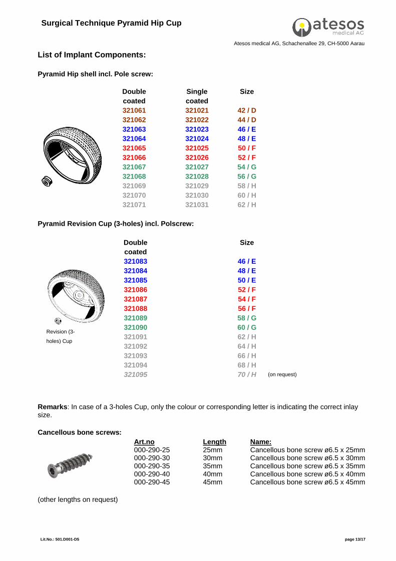
List of Implant Components:
Pyramid Hip shell incl. Pole screw:
Double
coated
Single
coated
Size
321061 321021 42 / D
321062 321022 44 / D
321063 321023 46 / E
321064 321024 48 / E
321065 321025 50 / F
321066 321026 52 / F
321067 321027 54 / G
321068 321028 56 / G
321069 321029 58 / H
321070 321030 60 / H
321071 321031 62 / H
Pyramid Revision Cup (3-holes) incl. Polscrew:
Double
coated
Size
321083 46 / E
321084 48 / E
321085 50 / E
321086 52 / F
321087 54 / F
321088 56 / F
321089 58 / G
321090 60 / G
321091 62 / H
321092 64 / H
321093 66 / H
321094 68 / H
321095 70 / H Remarks: In case of a 3-holes Cup, only the colour or corresponding letter is indicating the correct inlay size.
Cancellous bone screws:
Art.no Length Name: 000-290-25 25mm Cancellous bone screw ø6.5 x 25mm 000-290-30 30mm Cancellous bone screw ø6.5 x 30mm 000-290-35 35mm Cancellous bone screw ø6.5 x 35mm 000-290-40 40mm Cancellous bone screw ø6.5 x 40mm 000-290-45 45mm Cancellous bone screw ø6.5 x 45mm
(other lengths on request)
Revision (3-
holes) Cup
(on request)

Surgical Technique Pyramid Hip Cup
Atesos medical AG, Schachenallee 29, CH-5000 Aarau
Lit.No.: 501.D001-D5 page 14/17
Pyramid PE Insert Standard & Hooded:
Ref. No. Size Remarks
Standard
331001 28 / D
331002 28 / E
331003 32 / F
331004 32 / G
331005 32 / H
Hooded
331006 28 / D
331007 28 / E
331008 32 / F
331009 32 / G
331010 32 / H
Pyramid PE x-link Insert Standard & Hooded:
Ref. No. Size Remarks
Standard
332001 28 / D
332002 32 / E
332011 32 / F
332012 32 / G
332013 32 / H
332003 36 / F
332004 36 / G
332005 36 / H
Hooded
332006 28 / D
332007 32 / E
332014 32 / F
332015 32 / G
332016 32 / H
332008 36 / F
332009 36 / G
332010 36 / H
Ceramic Inserts ( Manufacturer CeramTec GmbH Medical Products Division : Material Biolox
Delta® OR HIPER Medical AG, Oberkrämer: Material ELEC®plus )
Ref. No.
Ceramtec)
Ref. No.
(Hiper)
Cup size /
Ball head-ø
Remarks
XLW 18-Insert 28/35G
38.49.7188.515.20
ELEC®plus Insert 28/35-18
120000
28 / D
No
combination of
products from
CERAMTEC
and HIPER is
allowed at any
time!
XLW 18-Insert 32/39G
38.49.7188.525.20
ELEC®plus Insert 32/39-18 120210
32 / E
XLW 18-Insert 36/44G
38.49.7188.545.20
ELEC®plus Insert 36/44-18
120380
36 / F
XLW 18-Insert 36/48G
38.49.7188.555.20
ELEC®plus Insert 36/48-18
120400
36 / G
XLW 18-Insert 36/52G
38.49.7188.565.20
ELEC®plus Insert 36/52-18
120420
36 / H

Surgical Technique Pyramid Hip Cup
Atesos medical AG, Schachenallee 29, CH-5000 Aarau
Lit.No.: 501.D001-D5 page 15/17
Overview: Shells and Inserts

Surgical Technique Pyramid Hip Cup
Atesos medical AG, Schachenallee 29, CH-5000 Aarau
Lit.No.: 501.D001-D5 page 16/17
List of Instruments: Ref. No. Name / Size Remarks
Acetabulum Reamer Size 40 No Atesos product
Acetabulum Reamer Size 41 2) No Atesos product
Acetabulum Reamer Size 42 No Atesos product
Acetabulum Reamer Size 43 2) No Atesos product
Acetabulum Reamer Size 44 No Atesos product
Acetabulum Reamer Size 45 2) No Atesos product
Acetabulum Reamer Size 46 No Atesos product
Acetabulum Reamer Size 47 2) No Atesos product
Acetabulum Reamer Size 48 No Atesos product
Acetabulum Reamer Size 49 2) No Atesos product
Acetabulum Reamer Size 50 No Atesos product
Acetabulum Reamer Size 51 2) No Atesos product
Acetabulum Reamer Size 52 No Atesos product
Acetabulum Reamer Size 53 2) No Atesos product
Acetabulum Reamer Size 54 No Atesos product
Acetabulum Reamer Size 55 2) No Atesos product
Acetabulum Reamer Size 56 No Atesos product
Acetabulum Reamer Size 57 2) No Atesos product
Acetabulum Reamer Size 58 No Atesos product
Acetabulum Reamer Size 59 2) No Atesos product
Acetabulum Reamer Size 60 No Atesos product
Acetabulum Reamer Size 61 2) No Atesos product
Acetabulum Reamer Size 62 No Atesos product
Acetabulum Reamer Size 63 2) No Atesos product
Acetabulum Reamer Size 64 2) No Atesos product
Acetabulum Reamer Size 65 2) No Atesos product
Acetabulum Reamer Size 66 2) No Atesos product
Acetabulum Reamer Size 67 2) No Atesos product
Acetabulum Reamer Size 68 2) No Atesos product
Acetabulum Reamer Size 69 2) No Atesos product
Acetabulum Reamer Size 70 2) No Atesos product
Reaming shaft straight/standard with AO Connector No Atesos product
800191 Protection sleeve for reaming shaft straight/standard
Reaming shaft MIS with AO Connector 3) No Atesos product
800032 Trial Shell Size 42 2)
800033 Trial Shell Size 44 2)
800034 Trial Shell Size 46 2)
800035 Trial Shell Size 48 2)
800036 Trial Shell Size 50 2)
800037 Trial Shell Size 52 2)
800038 Trial Shell Size 54 2)
800039 Trial Shell Size 56 2)
800040 Trial Shell Size 58 2)
800041 Trial Shell Size 60 2)
800042 Trial Shell Size 62 2)
800043 Trial Shell Size 64 2)
800044 Trial Shell Size 66 2)
800028 Trial Shell Size 68 2)
800029 Trial Shell Size 70 2)
800061 Trial insert 42-44 / 28 2)
800062 Trial insert 46-48 / 32 2)

Surgical Technique Pyramid Hip Cup
Atesos medical AG, Schachenallee 29, CH-5000 Aarau
Lit.No.: 501.D001-D5 page 17/17
1) Optional, if cup set only is available (without stem set) 2) Optional 3) Optional for MIS application
Manufacturer: Atesos medical AG
Schachenallee 29 5000 Aarau, Switzerland
www.atesos.ch
Tel : +41 (0)62 823 15 15 Fax : +41 (0)62 823 26 94
This edition is subject to alterations, for actual valid surgical technique see webpage Atesos medical.
800063 Trial insert 50-52 / 36 2)
800064 Trial insert 54-56 / 36 2)
800065 Trial insert 58-62 / 36 2)
800105 Trial insert 46-48 / 28 2)
800106 Trial insert 50-52 / 32 2)
800107 Trial insert 54-56 / 32 2)
800108 Trial insert 58-62 / 32 2)
800109 Trial insert hooded 42-44 / 28 2)
800110 Trial insert hooded 46-48 / 32 2)
800111 Trial insert hooded 50-52 / 36 2)
800112 Trial insert hooded 54-56 / 36 2)
800113 Trial insert hooded 58-62 / 36 2)
800114 Trial insert hooded 46-48 / 28 2)
800115 Trial insert hooded 50-52 / 32 2)
800116 Trial insert hooded 54-56 / 32 2)
800117 Trial insert hooded 58-62 / 32 2)
800086 Inlay Seating instrument 'Octopus'
800087 Connector 28 Seating Instr. 'Octopus'
800088 Connector 32 Seating Instr. 'Octopus'
800089 Connector 36 Seating Instr. 'Octopus'
800090 Connector 28 hooded Seating Instr. 'Octopus'
800091 Connector 32 hooded Seating Instr. 'Octopus'
800092 Connector 36 hooded Seating Instr. 'Octopus'
800093 Connector for attachment Octopus 2)
800097 Seating instrument shell MIS 3)
800098 Cardan shaft 3)
800099 Connector to shell 3)
800102 Seating instrument shell straight
800103 Hammer 450g
800218 Hexagon Screwdriver SW 3.5 mm
800232 Hexagon Cardan Screwdriver SW 3.5 mm 2)
800223 Palpation hook
800229 Connector for trial ball heads 1)
800233 T-handle AO-coupling
800203 Trial ball head ø28 L 1)
800208 Trial ball head ø32 L 1)
800213 Trial ball head ø36 L 1)
Flexi-Bit drill ø3.2mm, length 30mm No Atesos product
Flexi-Bit drill ø3.2mm, length 60mm No Atesos product
Flexi-Bit drill ø4.5mm, length 30mm No Atesos product
Flexi-Bit drill ø4.5mm, length 60mm No Atesos product
Flexi-Bit shaft, length 180mm No Atesos product
Screw holding forcepts No Atesos product
Drilling jig ø3.2mm No Atesos product
Screw holding forcepts curved (2 pcs.) No Atesos product