Surgical Technique - Orthopedic Designs North America, Inc. · Implant Removal 26 Product...
38
Self-Locking Nail with DistalFix Technology Surgical Technique
Transcript of Surgical Technique - Orthopedic Designs North America, Inc. · Implant Removal 26 Product...

Self-Locking Nail with
DistalFix Technology
Surgical Technique


Perfecting Fixation

Table of Contents
Surgical Technique
Introduction 5 TALON DISTALFIX SLN-Nail 5 Design Features 6 Indications/Contraindications 7 Surgical Technique 8 Patient Positioning 8 Determine the Starting Point 8 Opening the Cortex 9 Proximal Reaming 10 Determine Nail Length 11 Distal Reaming 12 Assemble the Targeting Guide 12 Attach the Nail 13 Verify Alignment 13 Insert the Nail 14 Place the Lag Screw Guide Pin 15 Determine Drilling Depth/Lag Screw Size 16 Drill for Lag Screw 17 Place the Lag Alignment Plug 17 Deploy Distal Nail Talons 18 Connect the Lag Screw and Lag Driver 19 Set the Depth Reference Indicator 19 Insert the Lag Screw 20 Engage the Lock Screw 21 Deploy Lag Screw Talons 21 Close Gap/Apply Compression 22 Set the Lag Screw Fixation—Fixed or Sliding 23 Release Lag Screw and Remove Sleeve 23 Remove the Targeting Guide 24 Insert End Cap 25 Implant Removal 26 Product Information Implant Catalog 30 Instrument Catalog 32 Important Medical Information 37 Note: This publication is provided to set forth a suggested surgical procedure. The physician should tailor
this procedure to the specific needs of the patient.
TALON DISTALFIX SLN-Nail

TALON DISTALFIX SLN-Nail ODi’s patented Talon Technology is the proven foundation for development of the Talon™ DistalFix™ Proximal Femoral Nail System. Having proven the effectiveness of a lag screw with integrated deployable Talons, our design team looked to improve the nail itself, which has undergone little innovation since cephalomedullary devices became popular in the latter portions of the 20th century. Subtle differences do exist among nail designs currently available (i.e. material, radius of curvature, set screw mechanism, proximal bend, distal tip design). Our team looked at all aspects of proximal femur fractures—from patient considerations to surgeon and OR staff concerns—when developing the Talon™ DistalFix™ Proximal Femoral Nail System.
The Talon™ DistalFix™ Proximal Femoral Nail System features an advanced distal fixation method with patented Talon Technology, which eliminates the use of cortical locking screws. The integral Talons deploy from within the medullary canal, making the “free hand” technique of locking screw placement a thing of the past. Patient safety is brought to a new level with a minimally invasive surgical technique that requires fewer incisions and may reduce patient time under anesthesia. Another benefit of the DistalFix™ system is a reduction in radiation exposure to the patient, surgeon, and OR staff.
At ODi our design team was charged with a simple goal: improve patient care. To that end, they developed a state-of-the-art proximal femoral nail system that enhances safety at every level. Coupled with easy to use instruments, the Talon™ DistalFix™ Proximal Femoral Nail System puts ODi one step closer to achieving its goal of perfecting fixation. Luis Vega, MD Clinical Director Orthopedic Designs, Inc.

SLN-Nail — Design Features Integrated lock screw allows for sliding or fixed angle configuration
Nail Talons, deployable to a diameter of 38mm, reduce operative time, radiation exposure, number of incisions, and potential complications associated with locking screw placement
ALL TALONS ARE FULLY RETRACTABLE
Standard Nail Length: 220mm Proximal Diameter: 15.5mm Distal Diameter: 11mm Angles: 120°, 125°, 130° Lateral Bend: 4°
Long Nails Lengths: 300mm—420mm (20mm increments) Proximal Diameter: 15.5mm Distal Diameter: 11mm Angles: 120°, 125°, 130° Lateral Bend: 4°
Radius of Curvature: 2m Anteversion: 10°
4° lateral bend for trochanteric insertion
Small 15.5mm proximal diameter for minimal bone removal and preservation of lateral wall of the greater trochanter
Lag Screw Lengths: 70mm—120mm (5mm increments) Thread Diameter: 11.0mm Root Diameter: 8.2mm
U.S. Patents: 5,976,139 - 6,183,474 - 6,648,889 - 6,695,844
Lag screw Talons, deployable to a diameter of 28mm, engage the cortical bone of the femoral head/neck junction to improve rotational control, resistance to cutout, and provide unmatched compression Tapered lag screw anti-rotation flats, narrower towards the threads, allows intra-operative compression to be maintained post-operatively while still permitting dynamic sliding
Self-tapping dual lead thread requires fewer turns for Implantation

SLN-Nail — Indications
Contraindications Active local infection Metal sensitivity or allergic reaction to
foreign bodies Loss of bone stock or insufficient bone
quality to support the device Obliterated medullary canal Comminuted fractures Fractures of the distal third Femoral neck fractures
Indications The Talon™ DistalFix™ Proximal Femoral Nail’s primary indications are for fixation/stabilization of stable and unstable fractures of the proximal femur including: Intertrochanteric fractures, Pertrochanteric fractures, High subtrochanteric fractures
(without shaft extension) Combinations of these fractures. The long nail allows the
additional indication of low subtrochanteric fractures.
The device is intended to stabilize fragments of the fracture until bony union can occur.
Standard Nail Long Nail
NOTE: Lag Talons should only be deployed within the proximal fracture.
Nail Talons should only be deployed within the distal fracture.
Precautions The Talon™ DistalFix™ Proximal Femoral Nail System has not been evaluated for safety and compatibility in the MR environment. The Talon™ DistalFix™ Proximal Femoral Nail System has not been tested for heating or migration in the MR environment.

Patient Positioning The patient should be positioned supine on a fracture or other radiolucent table. Traction should be applied to the affected leg and it should be placed in slight adduction. This will aid in the reduction and place the greater trochanter and femoral shaft in a more accessible position. The unaffected leg should be flexed at the hip and knee and then abducted and slightly internally rotated. This position allows complete fluoroscopic visualization of the affected hip. Centering the axis of rotation of the C-arm on the femoral neck of the affected hip will ensure that AP and Lateral views of the proximal femur can be easily obtained. An attempt at a closed reduction should be made prior to prepping and draping the patient.
Surgical Technique
The entry point for the nail is in line with the medullary canal in the lateral view. This should be at the junction of the anterior one-third and posterior two-thirds of the greater trochanter. In the AP view, the 4˚ lateral bend of the proximal nail pushes the entry point slightly lateral to the tip of the greater trochanter.
Determine the Starting Point

Trocar Tip Guide Wire SLN-T33 / SLN-T35
Curved Entry Awl SLN-T16
Opening the Cortex Option 1: Place a 3.0mm Trocar Tip Guide Wire through the cannulated Curved Entry Awl. Use the awl as a guide to introduce the guide wire into the proximal femur, advancing it with the T-Handle Pin Puller. Aim for the center of the medullary canal. Confirm the trajectory of the wire in both the AP and lateral planes using the C-arm. If necessary, withdraw the guide wire to the level of the cortical bone and adjust its direction by way of the awl. When satisfied with its trajectory, advance it to a depth of approximately 8-9cm or just past the lesser trochanter. Option 2: Using a 3.0mm Trocar Tip Guide Wire and a power driver, introduce the guide wire through the entry point aiming for the center of the medullary canal. Confirm the trajectory of the wire in both the AP and lateral planes using the C-arm. If necessary, withdraw the guide wire to the level of the cortical bone and adjust its direction. When satisfied with its trajectory, advance it to a depth of approximately 8-9cm or just past the lesser trochanter.
T-Handle Pin Puller THN-T03
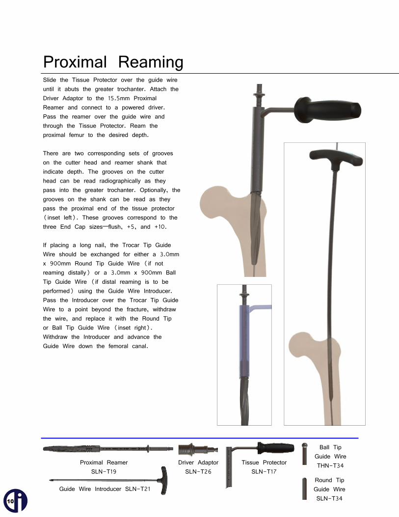
Slide the Tissue Protector over the guide wire until it abuts the greater trochanter. Attach the Driver Adaptor to the 15.5mm Proximal Reamer and connect to a powered driver. Pass the reamer over the guide wire and through the Tissue Protector. Ream the proximal femur to the desired depth. There are two corresponding sets of grooves on the cutter head and reamer shank that indicate depth. The grooves on the cutter head can be read radiographically as they pass into the greater trochanter. Optionally, the grooves on the shank can be read as they pass the proximal end of the tissue protector (inset left). These grooves correspond to the three End Cap sizes—flush, +5, and +10. If placing a long nail, the Trocar Tip Guide Wire should be exchanged for either a 3.0mm x 900mm Round Tip Guide Wire (if not reaming distally) or a 3.0mm x 900mm Ball Tip Guide Wire (if distal reaming is to be performed) using the Guide Wire Introducer. Pass the Introducer over the Trocar Tip Guide Wire to a point beyond the fracture, withdraw the wire, and replace it with the Round Tip or Ball Tip Guide Wire (inset right). Withdraw the Introducer and advance the Guide Wire down the femoral canal.
Proximal Reamer SLN-T19
Tissue Protector SLN-T17
Proximal Reaming
Driver Adaptor SLN-T26
Guide Wire Introducer SLN-T21
Ball Tip Guide Wire THN-T34
Round Tip Guide Wire SLN-T34

With a 3.0mm x 900mm Round Tip or Ball Tip Guide Wire in the canal, place the Radiographic Talon Template over the distal femur to determine the length of the longest nail recommended for the given patient. The Talons span a distance of 38mm across when fully deployed. Variation in bone dimensions makes it critical to confirm a chosen nail will achieve sufficient cortical purchase. Position the template such that all four points reside in cortical bone. The distal edge of the template (closest to the knee) indicates the tip of the nail. Withdraw or advance the guide wire until its tip is at the same level as the distal edge of the template (top inset). Unfold the Nail-Guide Wire Ruler and slide it over the guide wire and thru the Tissue Protector until the foot abuts the greater trochanter (middle inset). Read the suggested nail length measurement at the end of the guide wire (bottom inset). This reading indicates the longest nail recommended for the given patient ensuring adequate Talon purchase. Note that this measurement is a direct reading to the distal tip of the guide wire. Actual nail length is determined by the surgeon.
Determine Nail Length (long nail only)
Folding Nail-Guide Wire Ruler SLN-T37
Radiographic Talon Template SLN-T09

Mate the radiolucent Guide Arm to the Guide Handle with the Handle-Arm Connector Screw and secure using the 7mm Hex Ball Driver and Ratcheting Axial Handle. Place the Lag Guide Pin Placement Aid into the channel grooves at the top of the Guide Arm (top inset). Insert the Guide Arm Lock into the bottom of the Guide Arm and engage the screw (bottom inset). Do not tighten at this time.
Assemble the Targeting Guide
Guide Arm SLN-T03-01
7mm Hex Ball Driver SLN-T15
Guide Handle SLN-T03-02
Ratcheting Axial Handle SLN-T04
Modular Cutter Head SLN-T02-XXX
Guide Arm Lock SLN-T03-05
Lag Guide Pin Placement Aid SLN-T03-06 Handle-Arm Connector Screw
SLN-T03-03
Using the C-arm, ensure that fracture reduction has been maintained to this point. Place the 9mm Modular Cutter Head on the Flexible Reamer Shaft and pass over the guide wire. Advance the reamer with steady pressure to the desired depth. Back the reamer out, taking care to leave the guide wire in place, and exchange the cutter head for the next largest size and repeat. It is recommended that the canal be reamed to at least 1mm larger than the nail diameter of 11mm. Modular Cutter Heads range in size from 9mm to 13mm in 1mm increments. NOTE: DISTAL REAMING SHOULD ALWAYS BE DONE OVER A BALL TIP GUIDE WIRE.
Distal Reaming
Flexible Reamer Shaft SLN-T01

Mate the desired nail to the guide assembly with the Nail-Guide Connector Screw and secure using the 7mm Hex Ball Driver and Ratcheting Axial Handle. Take care to align the corresponding laser etched reference lines on the nail and Guide Handle (inset).
Verify proper alignment of the nail and guide assembly by inserting the Lag Guide Sleeve through the corresponding targeting hole in the Guide Arm. Advance the guide sleeve to contact the nail and tighten the Guide Arm Lock. Insert the Lag Alignment Plug and make sure that it passes through the nail properly. If misaligned, loosen the connection between the handle and the nail. Align the nail with the aid of the Plug and re-tighten the connection between nail and handle. Once well aligned, loosen the Guide Arm Lock and remove the Guide Sleeve and Lag Alignment Plug in preparation for nail insertion.
Lag Guide Sleeve SLN-T23
Verify Alignment
Attach the Nail
Nail-Guide Connector Screw SLN-T03-04
7mm Hex Ball Driver SLN-T15 Ratcheting Axial Handle SLN-T04
Lag Alignment Plug SLN-T31

NOTE: IF THE BALL TIP GUIDE WIRE WAS USED FOR DISTAL REAMING IT MUST BE EXCHANGED NOW FOR A ROUND TIP GUIDE WIRE. THE BALL TIP WILL NOT PASS THRU THE DISTAL TALON MECHANISM. Pass the nail over the guide wire and insert it into the femoral canal. It is recommended that the Impactor be attached to the Guide Handle prior to nail insertion. This will provide a platform on which to apply steady pressure to insert the nail. Fully thread the Impactor onto the Guide Handle then loosen 1/4 turn. This will make removing the Impactor easier. While applying pressure, use gentle twisting movements to advance the nail down the femur. The Impactor can be struck with the Slotted Slap Hammer to assist with nail insertion, if necessary. If considerable resistance is encountered, remove the nail and enlarge the canal through distal reaming. NOTE: DO NOT DIRECTLY STRIKE THE GUIDE ARM WITH THE SLAP HAMMER OR ANY OTHER MALLET.
Insert the Nail
Impactor/Extractor SLN-T27
Slotted Slap Hammer SLN-T07

Insert the Lag Guide Pin Obturator into the Lag Guide Sleeve and introduce the assembly through the corresponding hole in the Guide Arm and advance to the level of the skin. Make a small stab incision at the tip of the sleeve/obturator assembly and pass through the skin. Continue to advance the guide sleeve and obturator until the tip contacts the lateral cortex of the femur (middle inset). Verify radiographically that the sleeve is in contact with the femoral cortex and tighten the Guide Arm Lock. The 7mm Hex Ball Driver can be used to tighten the Guide Arm Lock, if necessary (bottom inset). NOTE: THE GUIDE ARM LOCK MUST BE TIGHTLY SECURED. THE LENGTH AND ULTIMATE POSITION OF THE LAG SCREW DEPEND ON THE LAG GUIDE SLEEVE REMAINING IN THE SAME POSITION THROUGHOUT THE PROCEDURE. Extend the Lag Guide Pin Placement Aid (top inset). The Lag Guide Pin Placement Aid will assist in ensuring the Guide Pin is placed with the correct version. When the two arms of the Lag Guide Pin Placement Aid overlap and appear as one on the lateral x-ray (bottom image), the direction of the Guide Pin can be accurately determined. Rotate the Guide Arm until the desired version is obtained.
Place the Lag Screw Guide Pin
Lag Guide Sleeve SLN-T23
Lag Guide Pin Obturator SLN-T22
7mm Hex Ball Driver
SLN-T15
Ratcheting Axial Handle SLN-T04

Place the foot of the Lag Screw Guide Pin Ruler against the knob of the guide sleeve, saddling the obturator shaft. Read the suggested lag screw length from the end of the guide pin (approximately 99mm in this illustration). If between graduations, select the next largest size. NOTE: THE RULER IS CALIBRATED TO THE TIP OF THE GUIDE PIN. ACTUAL DRILLING DEPTH AND LAG SCREW SIZE ARE AT THE DISCRETION OF THE SURGEON.
Determine Drilling Depth/Lag Screw Size
Lag Screw Guide Pin Ruler SLN-T18
Insert the Lag Guide Pin through the Obturator. Apply steady pressure to advance the guide pin through the lateral cortex of the femur. The ideal position of the guide pin is slightly inferior of central on the AP view and central on the lateral view. The pin should be advanced into the subchondral bone of the femoral head to within 3-6mm of the joint space radiographically. NOTE: THE POSITION OF THE GUIDE PIN IS OF CRITICAL IMPORTANCE, AS IT WILL DETERMINE THE ULTIMATE POSITION OF THE LAG SCREW. REPOSITION IF NECESSARY.
Place the Lag Screw Guide Pin (cont.)
Lag Guide Pin SLN-T25

Drill for Lag Screw Set the Lag Drill Stop to the depth determined with the Lag Screw Guide Pin Ruler in the previous step (top right inset). Remove the obturator from the sleeve and pass the Lag Drill over the guide pin. Advance the Lag Drill until the Lag Drill Stop contacts the sleeve (bottom left inset). Remove the Lag Drill.
Place the Lag Alignment Plug Pass the Lag Alignment Plug through the sleeve. The plug will pass through the lag screw hole in the nail. Advance the plug with the reference window parallel to the Guide Arm (top inset) until it is fully inserted and the proximal knob contacts the sleeve. Once inserted, spin the plug 90° (middle inset) until the reference window is perpendicular to the Guide Arm (bottom inset). This will ensure maximum space for the Nail Talon Deployment Driver to pass. The Lag Alignment Plug serves to hold the reduction and maintain nail position as the distal nail Talons are deployed.
Lag Alignment Plug SLN-T31
Lag Drill SLN-T28 Lag Drill Stop SLN-T29
READ HERE
REFERENCE WINDOW

Deploy Distal Nail Talons Attach the Nail Talon Deployment Driver to the Torque-Limiting Handle and pass the deployment driver down the nail. The guide pin will deflect slightly to allow passage down the shaft. Continue to slide the driver down the nail until engaging the distal nail Talons. Turn the driver clockwise to deploy the Talons. Approximately 18 complete turns of the handle will advance the Talons from a retracted to a fully deployed position. Because the anterior Talon is most likely to fully penetrate the cortex first, monitor Talon deployment by way of the C-arm positioned for a lateral view of the distal femur. NOTE: DEPLOYMENT CAN BE STOPPED AT ANY TIME. TALONS NEED NOT BE FULLY DEPLOYED. A CONSISTENT RESISTANCE SHOULD BE FELT DURING DEPLOYMENT UNTIL THE CORTEX IS REACHED. A SUDDEN INCREASE IN RESISTANCE MARKS CORTICAL CONTACT. CHECK THE DEPLOY-MENT PROGRESS WITH FLUOROSCOPY AND CONTINUE UNTIL THE TORQUE LIMITING HANDLE TRIPS OR YOU ARE RADIO-GRAPHICALLY INDICATED TO STOP. FULL TALON DEPLOYMENT CAN BE SEEN WHEN THE TALONS RESIDE IN THE META-PHYSEAL REGION OF THE FEMUR. TALONS DEPLOYED IN THE FEMORAL SHAFT MAY ONLY DEPLOY A FEW MILLIMETERS BEFORE REACHING THE TORQUE LIMIT. Talons are designed to penetrate the cortical bone. Care should be taken to avoid excessive perforation through the cortical bone and into soft tissue. TALONS SHOULD NEVER BE DEPLOYED USING A POWERED DRIVER.
Torque Limiting T-Handle SLN-T05
Nail Talon Deployment Driver SLN-T20
Nail Talon Deployment Driver (Short) SLN-T20S

Connect the Lag Screw and Lag Driver Pass the Lag Driver Connector Screw through the Lag Driver. Mate the chosen lag screw with the driver and secure by tightening the connector screw.
Set the Depth Reference Indicator The Depth Reference Indicator (aka Lag Driver Compression Knob) sets the relative depth at which the lag screw will be placed. If the lag screw size matches the depth that was drilled (i.e. drilled to 95mm and are placing a 95mm lag screw), the indicator should be set to “0”. If a smaller lag screw than what was drilled is being used, as in the case where a significant fracture gap is present, the indicator should be set to the difference between the depth drilled and lag screw size chosen (i.e. if 100mm was drilled and a 95mm lag screw is being used, the indicator should be set at “+5” [100mm-95mm]).
Lag Driver Connector Screw SLN-T24
Lag Driver with Compression Knob SLN-T30 and SLN-T30-03
READ HERE
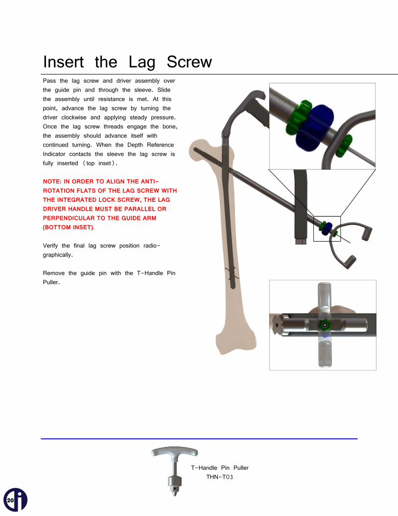
Insert the Lag Screw Pass the lag screw and driver assembly over the guide pin and through the sleeve. Slide the assembly until resistance is met. At this point, advance the lag screw by turning the driver clockwise and applying steady pressure. Once the lag screw threads engage the bone, the assembly should advance itself with continued turning. When the Depth Reference Indicator contacts the sleeve the lag screw is fully inserted (top inset). NOTE: IN ORDER TO ALIGN THE ANTI-ROTATION FLATS OF THE LAG SCREW WITH THE INTEGRATED LOCK SCREW, THE LAG DRIVER HANDLE MUST BE PARALLEL OR PERPENDICULAR TO THE GUIDE ARM (BOTTOM INSET). Verify the final lag screw position radio-graphically. Remove the guide pin with the T-Handle Pin Puller.
T-Handle Pin Puller THN-T03

Engage the Lock Screw With the Lag Driver handle positioned parallel or perpendicular to the targeting arm, connect the 5mm Hex Ball Driver to the Ratcheting Axial Handle. Introduce the 5mm Hex Ball Driver through the proximal end of the nail to adjust the integral lock screw. Turn the driver clockwise approximately one full turn to temporarily engage the lock screw. Leave the driver in place during deployment of the lag screw talons.
Deploy Lag Screw Talons Connect the Lag Talon Deployment Driver to the Torque Limiting T-Handle and introduce it through the lag driver until contact is made with the Talons. Turn the driver clockwise to deploy the Talons. There will be little resistance the first several turns as the driver engages the mechanism. Deployment begins once resistance is felt and full deployment requires approximately 18 complete turns of the driver. NOTE: DEPLOYMENT CAN BE STOPPED AT ANY TIME. THE EXTENT OF TALON DEPLOY-MENT IS CONTROLLED BY, AND IS AT THE DISCRETION OF, THE SURGEON. Talons are designed to penetrate the cortical bone at the junction of the femoral head and neck. Care should be taken to avoid penetration of the Talons through the weight-bearing surface of the femoral head. TALONS SHOULD NEVER BE DEPLOYED USING A POWERED DRIVER.
5mm Hex Ball Driver SLN-T14
Lag Talon Deployment Driver SLN-T12
Ratcheting Axial Handle SLN-T04
Torque Limiting T-Handle SLN-T05

Close Gap/Apply Compression (optional) RELEASE TRACTION ON THE LEG PRIOR TO APPLYING COMPRESSION ACROSS THE FRACTURE. To close a fracture gap and/or apply interfragmentary compression, first disengage the lock screw by turning the 5mm Hex Ball Driver 1/4 turn counter-clockwise. This will allow the lag screw to slide but not rotate. With the lock screw disengaged, rotate the Lag Driver Compression Knob (aka Depth Reference Indicator) clockwise. As the compression knob turns, the Lag Screw/Lag Driver assembly is pulled back, thus closing any gap and applying compression. If the Depth Reference Indicator was set to “0”, then 5mm of compression can be applied. If it was set to “+5”, then 10mm of compression can be applied. If set to “+10”, 15mm of compression can be applied.

Set the Lag Screw Fixation Type Whether compression is applied or not, the type of lag screw fixation—fixed or sliding—must be set by means of the Lock Screw. Fixed: The fixed lag screw position does not allow for rotation or sliding. It is achieved by turning the 5mm Hex Ball Driver clockwise until the Lock Screw is fully tightened against the lag screw anti-rotation flat. Sliding: The sliding lag screw position allows free lateral sliding of the lag screw while preventing rotation. The design of the anti-rotation flats is such that the Lock Screw prevents medial migration of the lag screw. This also means that any intra-operative compression that is applied can be maintained post-operatively while preserving the ability to further collapse as the patient bears weight. To place the Lock Screw to allow for sliding, turn the 5mm Hex Ball Driver clockwise until fully tightened against the lag screw anti-rotation flat. Then, turn the driver 1/8 turn counterclockwise to loosen the Lock Screw slightly, allowing the lag screw to slide freely in the lateral direction.
Release Lag Screw and Remove Sleeve With the fixation set, release the lag screw from the Lag Driver by turning the Lag Driver Connector Screw counterclockwise (use the 5mm Hex Ball Driver and Ratcheting Axial Handle, if necessary). Withdraw the Lag Driver from the sleeve. Loosen the Guide Arm Lock and remove the sleeve. Use the 7mm Hex Ball Driver and Ratcheting Axial Handle (not shown) to release the Guide Arm Lock, if needed.

Remove the Targeting Guide Select the 7mm Hex Ball Driver and the Ratcheting Axial Handle. Insert the driver into the Guide Handle and turn counterclockwise to loosen the Nail-Handle Connector Screw, releasing the nail from the targeting guide.
Ratcheting Axial Handle SLN-T04
7mm Hex Ball Driver SLN-T15

Insert End Cap (optional) Select the 5mm Hex Ball Driver and the Ratcheting Axial Handle. Place the End Cap on the driver and, taking care not to drop it in the soft tissue, introduce it into the proximal end of the nail. Turn the driver clockwise until the End Cap is fully tightened.
Ratcheting Axial Handle SLN-T04
5mm Hex Ball Driver SLN-T14
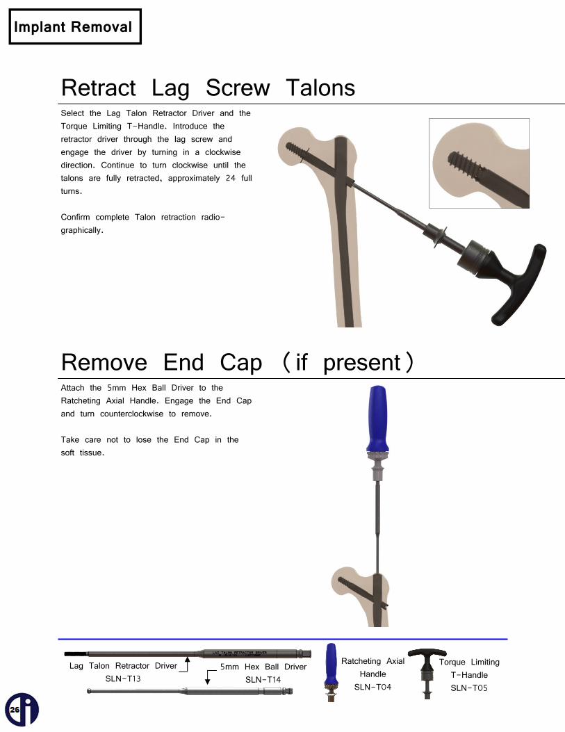
Retract Lag Screw Talons Select the Lag Talon Retractor Driver and the Torque Limiting T-Handle. Introduce the retractor driver through the lag screw and engage the driver by turning in a clockwise direction. Continue to turn clockwise until the talons are fully retracted, approximately 24 full turns. Confirm complete Talon retraction radio-graphically.
Remove End Cap (if present) Attach the 5mm Hex Ball Driver to the Ratcheting Axial Handle. Engage the End Cap and turn counterclockwise to remove. Take care not to lose the End Cap in the soft tissue.
Implant Removal
Lag Talon Retractor Driver SLN-T13
5mm Hex Ball Driver SLN-T14
Ratcheting Axial Handle SLN-T04
Torque Limiting T-Handle SLN-T05

Disengage Lock Screw Attach the 5mm Hex Ball Driver to the Ratcheting Axial Handle. Engage the Lock Screw and turn counterclockwise two full turns to clear the lag screw.
Remove Lag Screw Pass the Lag Connector Screw through the Lag Driver. In order to mate the Lag Driver with the lag screw, the driver handle must be in either the horizontal or vertical position. Once the driver is securely attached to the lag screw, turn the driver counterclockwise to remove the lag screw.
Ratcheting Axial Handle SLN-T04
5mm Hex Ball Driver SLN-T14 Lag Driver Connector Screw SLN-T24
Lag Driver with Compression Knob SLN-T30 and SLN-T30-03

Retract Distal Nail Talons Select the Lag Alignment Plug and pass it through the lag screw hole in the nail. The reference slot between the grip knobs of the alignment plug must be oriented vertically to allow passage of the Nail Talon Deployment Driver. The plug will prevent nail rotation while retracting the distal nail Talons. Attach the Nail Talon Deployment Driver to the Torque Limiting T-Handle and pass the driver down the nail until it engages the distal nail Talons. Turn the driver counterclockwise to retract the Talons. If fully deployed, it will take approximately 18 full turns for complete retraction. Confirm complete Talon retraction radio-graphically.
Lag Alignment Plug SLN-T31
Nail Talon Deployment Driver SLN-T20 or SLN-T20S Ratcheting Axial Handle
SLN-T04
Torque Limiting T-Handle SLN-T05

Remove Nail Select the Impactor/Extractor and attach it to the proximal end of the nail by turning the Impactor/Extractor clockwise until fully engaged. Use the Slotted Slap Hammer to extract the nail as needed.
Impactor/Extractor SLN-T27
Slotted Slap Hammer SLN-T07

TALON DISTALFIX SLN-Nail — Implants
Catalog Number Description
SLN-011-070 Lag Screw — Ø11mm x 70mm SLN-011-075 Lag Screw — Ø11mm x 75mm SLN-011-080 Lag Screw — Ø11mm x 80mm SLN-011-085 Lag Screw — Ø11mm x 85mm SLN-011-090 Lag Screw — Ø11mm x 90mm SLN-011-095 Lag Screw — Ø11mm x 95mm SLN-011-100 Lag Screw — Ø11mm x 100mm SLN-011-105 Lag Screw — Ø11mm x 105mm SLN-011-110 Lag Screw — Ø11mm x 110mm SLN-011-115 Lag Screw — Ø11mm x 115mm SLN-011-120 Lag Screw — Ø11mm x 120mm SLN-155-000 End Cap — Ø15.5mm x Flush SLN-155-005 End Cap — Ø15.5mm x 5mm SLN-155-010 End Cap — Ø15.5mm x 10mm SLN-120-220 Short Nail — 220mm x 120o Universal SLN-125-220 Short Nail — 220mm x 125o Universal SLN-130-220 Short Nail — 220mm x 130o Universal
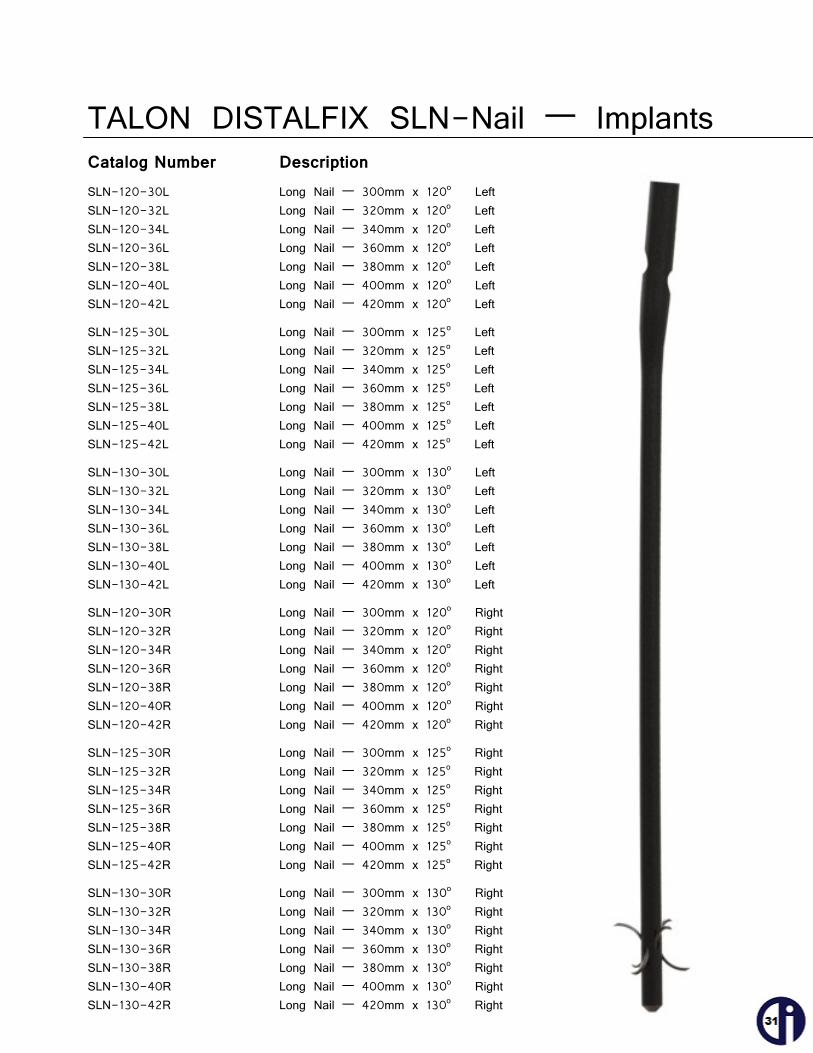
TALON DISTALFIX SLN-Nail — Implants
Catalog Number Description
SLN-120-30L Long Nail — 300mm x 120o Left SLN-120-32L Long Nail — 320mm x 120o Left SLN-120-34L Long Nail — 340mm x 120o Left SLN-120-36L Long Nail — 360mm x 120o Left SLN-120-38L Long Nail — 380mm x 120o Left SLN-120-40L Long Nail — 400mm x 120o Left SLN-120-42L Long Nail — 420mm x 120o Left
SLN-125-30L Long Nail — 300mm x 125o Left SLN-125-32L Long Nail — 320mm x 125o Left SLN-125-34L Long Nail — 340mm x 125o Left SLN-125-36L Long Nail — 360mm x 125o Left SLN-125-38L Long Nail — 380mm x 125o Left SLN-125-40L Long Nail — 400mm x 125o Left SLN-125-42L Long Nail — 420mm x 125o Left
SLN-130-30L Long Nail — 300mm x 130o Left SLN-130-32L Long Nail — 320mm x 130o Left SLN-130-34L Long Nail — 340mm x 130o Left SLN-130-36L Long Nail — 360mm x 130o Left SLN-130-38L Long Nail — 380mm x 130o Left SLN-130-40L Long Nail — 400mm x 130o Left SLN-130-42L Long Nail — 420mm x 130o Left
SLN-120-30R Long Nail — 300mm x 120o Right SLN-120-32R Long Nail — 320mm x 120o Right SLN-120-34R Long Nail — 340mm x 120o Right SLN-120-36R Long Nail — 360mm x 120o Right SLN-120-38R Long Nail — 380mm x 120o Right SLN-120-40R Long Nail — 400mm x 120o Right SLN-120-42R Long Nail — 420mm x 120o Right
SLN-125-30R Long Nail — 300mm x 125o Right SLN-125-32R Long Nail — 320mm x 125o Right SLN-125-34R Long Nail — 340mm x 125o Right SLN-125-36R Long Nail — 360mm x 125o Right SLN-125-38R Long Nail — 380mm x 125o Right SLN-125-40R Long Nail — 400mm x 125o Right SLN-125-42R Long Nail — 420mm x 125o Right
SLN-130-30R Long Nail — 300mm x 130o Right SLN-130-32R Long Nail — 320mm x 130o Right SLN-130-34R Long Nail — 340mm x 130o Right SLN-130-36R Long Nail — 360mm x 130o Right SLN-130-38R Long Nail — 380mm x 130o Right SLN-130-40R Long Nail — 400mm x 130o Right SLN-130-42R Long Nail — 420mm x 130o Right

TALON DISTALFIX SLN-Nail — Instruments
Part Number Description SLN-T01 Modular Flexible Reamer Shaft SLN-T02-009 9mm Modular Reamer Cutter Head SLN-T02-010 10mm Modular Reamer Cutter Head SLN-T02-011 11mm Modular Reamer Cutter Head SLN-T02-012 12mm Modular Reamer Cutter Head SLN-T02-013 13mm Modular Reamer Cutter Head
SLN-T03-01 Guide Arm SLN-T03-02 Guide Handle
SLN-T03-03 Handle-Arm Connector Screw
SLN-T03-04 Nail-Guide Connector Screw SLN-T03-05 Guide Arm Lock
SLN-T03-06 Lag Guide Pin Placement Aid
SLN-T04 Ratcheting Axial Handle 1/4” Sq
SLN-T05 Torque Limiting T-Handle
SLN-T07 Slotted Slap Hammer
TALON DISTALFIX SLN-Nail — Instruments
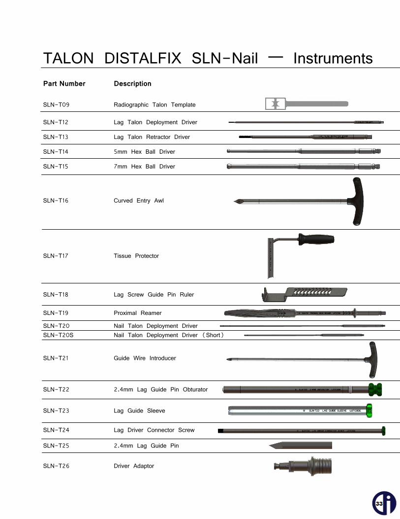
Part Number Description SLN-T09 Radiographic Talon Template SLN-T12 Lag Talon Deployment Driver
SLN-T13 Lag Talon Retractor Driver
SLN-T14 5mm Hex Ball Driver
SLN-T15 7mm Hex Ball Driver
SLN-T16 Curved Entry Awl SLN-T17 Tissue Protector
SLN-T18 Lag Screw Guide Pin Ruler SLN-T19 Proximal Reamer
SLN-T20 Nail Talon Deployment Driver SLN-T20S Nail Talon Deployment Driver (Short) SLN-T21 Guide Wire Introducer
SLN-T22 2.4mm Lag Guide Pin Obturator
SLN-T23 Lag Guide Sleeve SLN-T24 Lag Driver Connector Screw
SLN-T25 2.4mm Lag Guide Pin SLN-T26 Driver Adaptor
TALON DISTALFIX SLN-Nail — Instruments
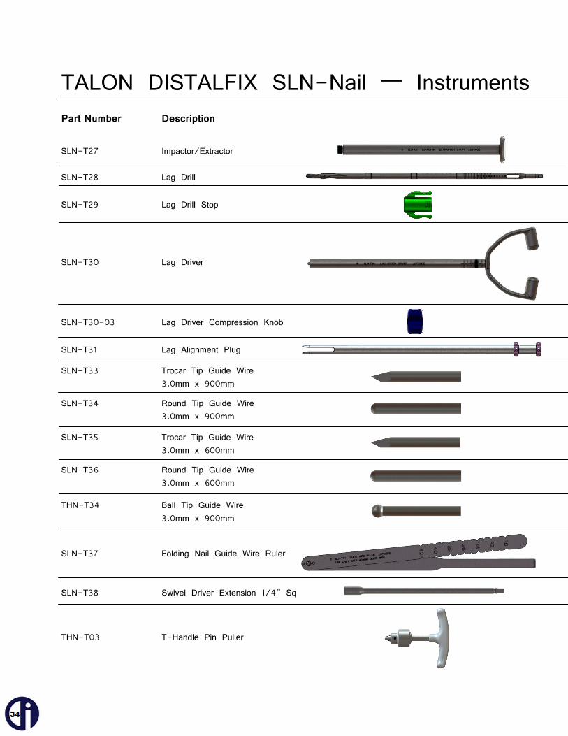
Part Number Description SLN-T27 Impactor/Extractor SLN-T28 Lag Drill SLN-T29 Lag Drill Stop SLN-T30 Lag Driver
SLN-T30-03 Lag Driver Compression Knob SLN-T31 Lag Alignment Plug
SLN-T33 Trocar Tip Guide Wire 3.0mm x 900mm
SLN-T34 Round Tip Guide Wire 3.0mm x 900mm
SLN-T35 Trocar Tip Guide Wire 3.0mm x 600mm
SLN-T36 Round Tip Guide Wire 3.0mm x 600mm
THN-T34 Ball Tip Guide Wire 3.0mm x 900mm
SLN-T37 Folding Nail Guide Wire Ruler
SLN-T38 Swivel Driver Extension 1/4” Sq
THN-T03 T-Handle Pin Puller
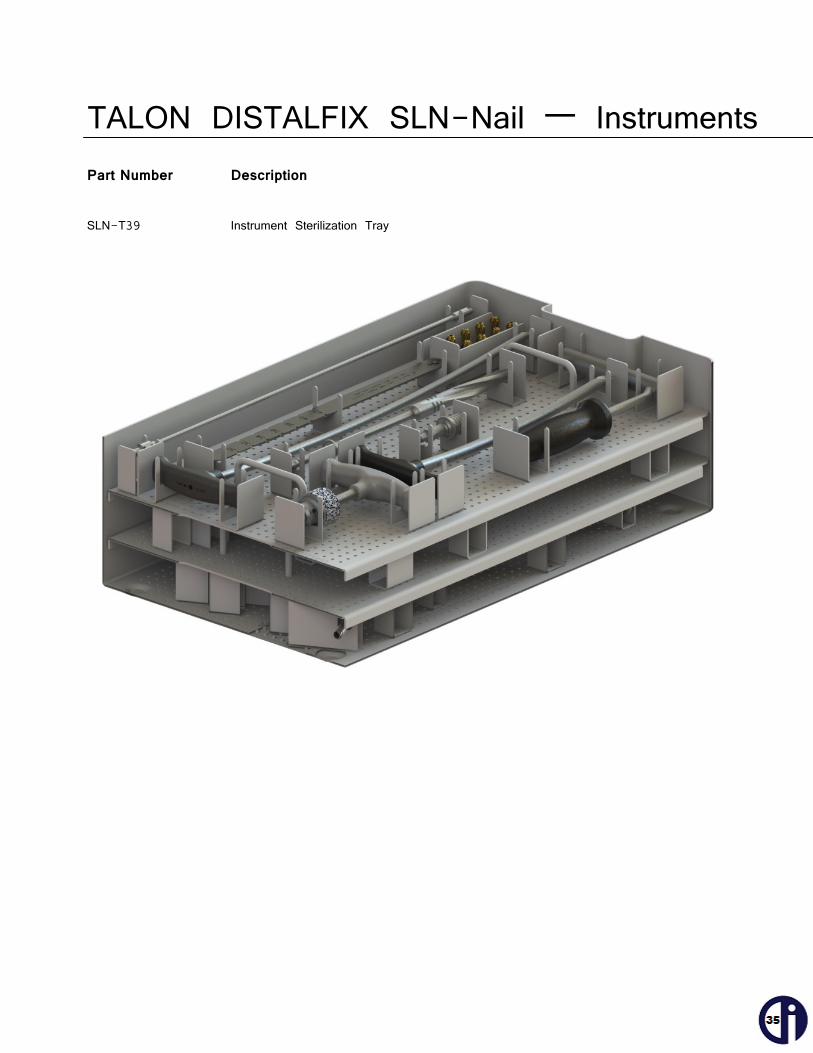
TALON DISTALFIX SLN-Nail — Instruments Part Number Description
SLN-T39 Instrument Sterilization Tray

Notes ________________________________________________________________________________________________________________________________________________________________________________________________________________________________________________________________________________________________________________________________________________________________________________________________________________________________________________________________________________________________________________________________________________________________________________________________________________________________________________________________________________________________________________________________________________________________________________________________________________________________________________________________________________________________________________________________________________________________________________________________________________________________________________________________________________________________________________________________________________________________________________________________________________________________________________________________________________________________________________________________________________________________________________________________________________________________________________________________________________________________________________________________________________________________________________________________________________________________________________________________________________________________________________________________________________________________________________________________________________________________________________________________________________________________________________________________________________________________________________________________________________________________________________________________________________________________________________________________________________________________________________________________________________________________________________________________________________________________________________________________________________________________________________________________________________________________________________________________________
The use of surgical implants provides the orthopedic surgeon a means of bone fixation and helps generally in the management of fractures and reconstructive surgeries. These implants are intended as an aid to normal healing, and are not intended to replace normal body structure or bear the weight of the body in the presence of incomplete bone healing. Delayed unions or nonunions, in the presence of load bearing or weight bearing, might eventually cause the implant to break, due to metal fatigue. All metal surgical implants are subject to repeated stress in use, which can result in metal fatigue. 1. NO PARTIAL WEIGHT BEARING OR NONWEIGHT BEARING DEVICE CAN BE EXPECTED TO WITHSTAND THE
UNSUPPORTED STRESSES OF FULL WEIGHT BEARING. Until firm bone union is achieved, the patient should employ adequate external support and restrict physical activities which would place stress upon the implant or allow movement at the fracture site and delay healing. Failure to immobilize a delayed union or nonunion of bone will result in excessive and repeated stresses, which are transmitted by the body to any temporary internal fixation device, prior to the healing of the fracture. Due to normal metal fatigue, these stresses can cause eventual bending or breakage of the device. Therefore, it is important that immobilization of the fracture is maintained until firm bony union (confirmed by clinical and roentgenographic examination) is established. Special precautions are necessary if a temporary internal fixation device is used to treat an unstable intertrochanteric fracture or subtrochanteric fracture. These fractures are more difficult to reduce and result in unusually strong unbalanced muscle forces, which cause greater stress to be transmitted to the temporary internal fixation device than with other types of femoral fractures. These stresses increase the possibility of implant bending or breakage. NOTE: Postoperative care is extremely important. The patient must be warned that noncompliance with postoperative instruction could lead to breakage of the implant, requiring revision surgery to remove the device.
2. CORRECT SELECTION OF THE IMPLANT IS EXTREMELY IMPORTANT. The potential for success in fracture fixation is increased by the selection of the proper size, shape and design of the implants. The size and shape of the human bone presents limiting restrictions on the size and strength of the implants.
3. Preoperative and operative procedures, including knowledge of surgical techniques, good reduction, and proper selection and placement of the implant are important considerations in the successful utilization of temporary internal fixation devices. See the specific surgical technique for surgical procedure.
4. In evaluating patients for orthopedic appliance application, the patient's weight, occupation, activity level, mental condition, foreign body sensitivity, and any degenerative diseases are of extreme importance to the eventual success of the procedure. These conditions must be evaluated as part of the preoperative planning.
5. CORRECT HANDLING OF IMPLANTS IS EXTREMELY IMPORTANT. The device should not be bent sharply, reverse bent, notched or scratched. All of these operations can produce defects in the surface finish and internal stress concentrations, which may become the focal point for eventual failure of the appliance. If metal screws, wire bands or other metallic devices are to be used together with a particular temporary internal fixation device, all such devices should be manufactured from materials having similar composition, to avoid the possibility of galvanic corrosion or other metallic reactions.
6. NO METALLIC SURGICAL IMPLANT SHOULD BE REUSED. Any metal implant, once used, should be discarded. Even though it appears undamaged, stresses from prior use may create small defects and internal stress patterns which may lead to fatigue failure.
7. Detailed written instructions on the use and limitations of the device should be given to the patient. If partial weight bearing is recommended or required prior to firm bony union, the patient must be warned that bending or breakage of the device are complications which may occur as a result of weight bearing or muscle activity. An active patient, debilitated or demented patient, who cannot properly use weight support devices, may be particularly at risk during postoperative rehabilitation.
8. REMOVAL OF THE DEVICE. While the surgeon must make the final decision on implant removal, it is the position of the Orthopedic Surgical Manufacturers Association that, whenever possible and practical for the individual patient, fixation devices should be removed once their service as an aid to healing is accomplished, particularly in younger more active patients.
9. SCREWS WARNING. This device is not approved for screw attachment or fixation to the posterior element (pedicles) of the cervical, thoracic, or lumbar spine.
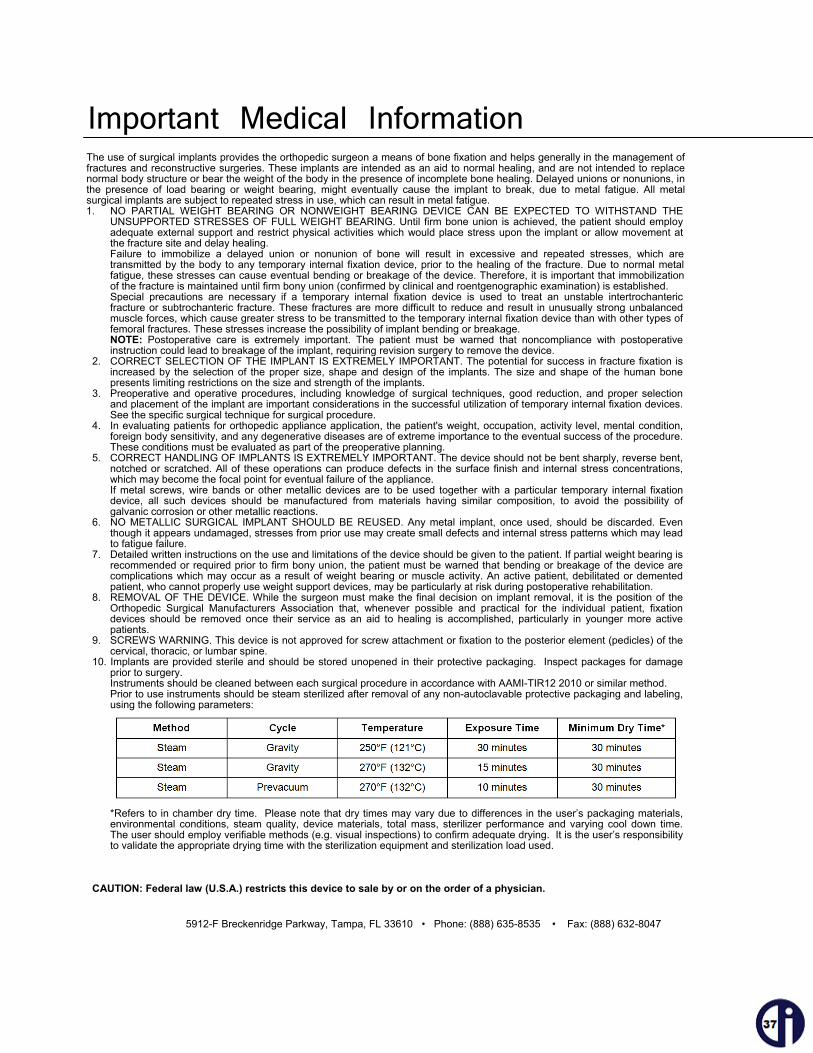
10. Implants are provided sterile and should be stored unopened in their protective packaging. Inspect packages for damage prior to surgery. Instruments should be cleaned between each surgical procedure in accordance with AAMI-TIR12 2010 or similar method. Prior to use instruments should be steam sterilized after removal of any non-autoclavable protective packaging and labeling, using the following parameters:
*Refers to in chamber dry time. Please note that dry times may vary due to differences in the user’s packaging materials, environmental conditions, steam quality, device materials, total mass, sterilizer performance and varying cool down time. The user should employ verifiable methods (e.g. visual inspections) to confirm adequate drying. It is the user’s responsibility to validate the appropriate drying time with the sterilization equipment and sterilization load used.
CAUTION: Federal law (U.S.A.) restricts this device to sale by or on the order of a physician.
5912-F Breckenridge Parkway, Tampa, FL 33610 • Phone: (888) 635-8535 • Fax: (888) 632-8047
Important Medical Information

5912-F Breckenridge Parkway Tampa, FL 33610
Phone: (888) 635-8535 Fax: (888) 632-8047 www.odi-na.com
7002, 4.0 ©2011 Orthopedic Designs North America, Inc. All Rights Reserved
Caution: Federal law (USA) restricts this device to sale by or on the order of a physician.