Surgical Techniquesynthes.vo.llnwd.net/o16/LLNWMB8/INT Mobile/Synthes...4 DePuy Synthes Cable System...
40
Cable System. For Orthopaedic Trauma Surgery. Surgical Technique This publication is not intended for distribution in the USA. Instruments and implants approved by the AO Foundation.
Transcript of Surgical Techniquesynthes.vo.llnwd.net/o16/LLNWMB8/INT Mobile/Synthes...4 DePuy Synthes Cable System...

Cable System. For Orthopaedic Trauma Surgery.
Surgical Technique
This publication is not intended for distribution in the USA.
Instruments and implants approved by the AO Foundation.

Image intensifier control
This description alone does not provide sufficient background for direct use of DePuy Synthes products. Instruction by a surgeon experienced in handling these products is highly recommended.
Processing, Reprocessing, Care and MaintenanceFor general guidelines, function control and dismantling of multi-part instruments, as well as processing guidelines for implants, please contact your local sales representative or refer to:http://emea.depuysynthes.com/hcp/reprocessing-care-maintenanceFor general information about reprocessing, care and maintenance of Synthes reusable devices, instrument trays and cases, as well as processing of Synthes non-sterile implants, please consult the Important Information leaflet (SE_023827) or refer to: http://emea.depuysynthes.com/hcp/reprocessing-care-maintenance

Cable System Surgical Technique DePuy Synthes 1
Table of Contents
Introduction Cable System 2
AO Principles 4
Indications and Contraindications 5
Surgical Technique Standard Cerclage Technique 6
Implant Removal 14
Tension-band Technique on the Olecranon 15
Implant Removal 17
Tension-band Technique on the Patella 18
Implant Removal 20
Trochanteric Reattachment Device 21
Implant Removal 30
Product Information Implants 31
Instruments 33
Cable System in Vario Case 35
MRI Information 36

2 DePuy Synthes Cable System Surgical Technique
The Synthes Cable System is primarily a cerclage system that consists of two different-sized cer-clage cables with crimp in three different materi-als, and new instruments for applying the cable assembly. The cable assemblies are available for stainless steel and titanium implant indications. They are designed for use with the Cerclage Posi-tioning Pins (for LC-DCP and LCP) and Cerclage Eyes. The Synthes Cable System is fully compatible with all Synthes plates and screws.
Ergonomically designed instrumentsA primary goal of development was an ergo-nomic, compact instrument design which simpli-fies handling and decreases application errors.
Multifunctional A variety of articles (implants and instruments) make the cable system a very versatile system, enabling it to be used for a wide range of applica-tions (e.g. periprosthetic fractures, temporary reduction).
Easy surgical techniqueAll implants and instruments were optimized without compromise for the specific tasks of a cable system. This simplifies the surgical technique (e.g. no contouring of plates necessary) and makes them easier to use.
Compatible with Synthes implants The Cable system is compatible with the existing Synthes plates and screws, both in stainless steel and titanium.
Cable System. For Orthopaedic Trauma Surgery.
Application Description

Cable System Surgical Technique DePuy Synthes 3
Temporary fixation to support reductionFor the temporary fixation of a cerclage cable, the cable tensioner can be removed without losing tension thanks to the temporary Ten-sion Holder.
Easy crimpingA ratchet mechanism controls the amount of crimp and deformation. The crimper auto -matically releases when the cable is crimped (no overcrimping or undercrimping possible).

4 DePuy Synthes Cable System Surgical Technique
AO Principles
In 1958, the AO formulated four basic principles which have become the guidelines for internal fixation:1
Anatomic reductionFracture reduction and fixation to restore anatomical func-tion.
Stable fixationStability by fixation with the cable system in combination with Synthes Implants as required by the nature of the frac-ture and the injury.
Preservation of blood supplyThe variety of cables provide better access, enabling the cer-clage cable to be passed around different sized and shaped bones while limiting tissue trauma and periosteal stripping and thus preserving the blood supply.
Early mobilizationWhen implanted, the cables and implants provide stable fracture fixation that allows early, pain-free mobilization.
1 M.E. Müller, M. Allgöwer, R. Schneider, and R. Willenegger (1991) AO Manual of Internal Fixation, 3rd Edition. Berlin: Springer.

Cable System Surgical Technique DePuy Synthes 5
Indications and Contraindications
Indications – Orthopaedic trauma surgery (incl. periprosthetic fractures,
femur fractures, olecranon fractures, patella fractures, humerus and ankle fractures)
– Acromioclavicular dislocation – Hip and acetabular fractures – Prophylactic banding in total joint replacements – Temporary fixation during open reductions – Reattachment of the greater trochanter following
osteotomy in total hip arthroplasty or fractures
Contraindications The cerclage cable B 1.0 mm may not be used for fractures of the femur, or for prophylactic banding during total joint replacements.
6 DePuy Synthes Cable System Surgical Technique
Standard Cerclage Technique
The following standard cerclage technique is explained using the example of a periprosthetic femoral fracture.
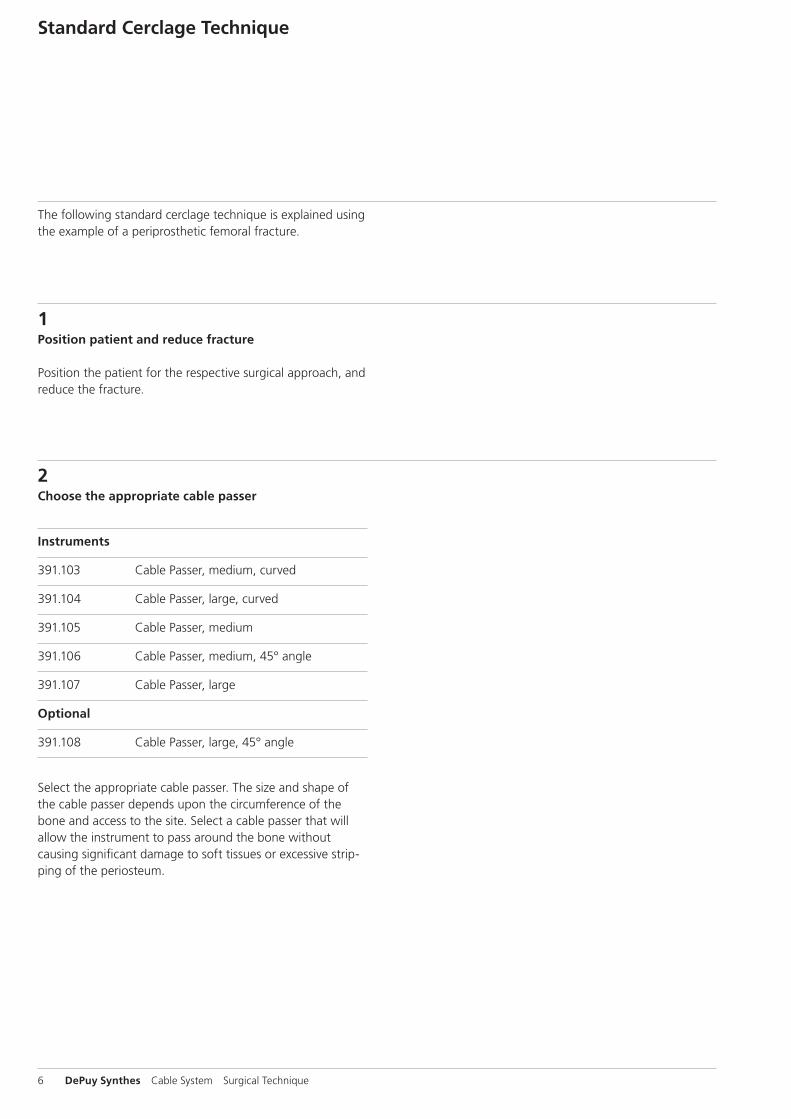
2Choose the appropriate cable passer
Instruments
391.103 Cable Passer, medium, curved
391.104 Cable Passer, large, curved
391.105 Cable Passer, medium
391.106 Cable Passer, medium, 45° angle
391.107 Cable Passer, large
Optional
391.108 Cable Passer, large, 45° angle
Select the appropriate cable passer. The size and shape of the cable passer depends upon the circumference of the bone and access to the site. Select a cable passer that will allow the instrument to pass around the bone without causing significant damage to soft tissues or excessive strip-ping of the periosteum.
1Position patient and reduce fracture
Position the patient for the respective surgical approach, and reduce the fracture.
3
Cable System Surgical Technique DePuy Synthes 7
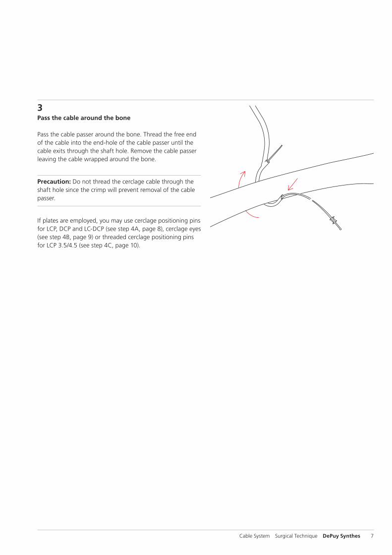
3Pass the cable around the bone
Pass the cable passer around the bone. Thread the free end of the cable into the end-hole of the cable passer until the cable exits through the shaft hole. Remove the cable passer leaving the cable wrapped around the bone.
Precaution: Do not thread the cerclage cable through the shaft hole since the crimp will prevent removal of the cable passer.
If plates are employed, you may use cerclage positioning pins for LCP, DCP and LC-DCP (see step 4A, page 8), cerclage eyes (see step 4B, page 9) or threaded cerclage positioning pins for LCP 3.5/4.5 (see step 4C, page 10).
8 DePuy Synthes Cable System Surgical Technique
Standard Cerclage Technique
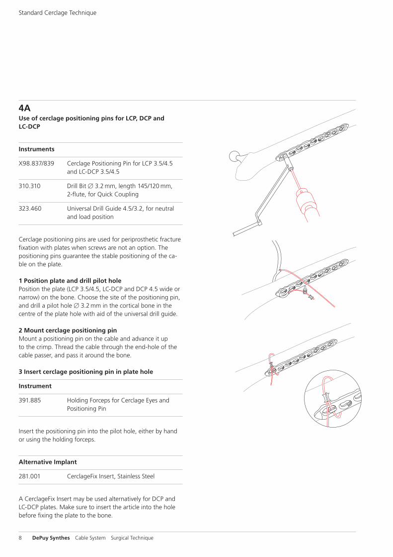
4AUse of cerclage positioning pins for LCP, DCP and LC-DCP
Instruments
X98.837/839 Cerclage Positioning Pin for LCP 3.5/4.5 and LC-DCP 3.5/4.5
310.310 Drill Bit B 3.2 mm, length 145/120 mm, 2-flute, for Quick Coupling
323.460 Universal Drill Guide 4.5/3.2, for neutral and load position
Cerclage positioning pins are used for periprosthetic fracture fixation with plates when screws are not an option. The positioning pins guarantee the stable positioning of the ca-ble on the plate.
1 Position plate and drill pilot holePosition the plate (LCP 3.5/4.5, LC-DCP and DCP 4.5 wide or narrow) on the bone. Choose the site of the positioning pin, and drill a pilot hole B 3.2 mm in the cortical bone in the centre of the plate hole with aid of the universal drill guide.
2 Mount cerclage positioning pinMount a positioning pin on the cable and advance it up to the crimp. Thread the cable through the end-hole of the cable passer, and pass it around the bone.
3 Insert cerclage positioning pin in plate hole
Instrument
391.885 Holding Forceps for Cerclage Eyes and Positioning Pin
Insert the positioning pin into the pilot hole, either by hand or using the holding forceps.
Alternative Implant
281.001 CerclageFix Insert, Stainless Steel
A CerclageFix Insert may be used alternatively for DCP and LC-DCP plates. Make sure to insert the article into the hole before fixing the plate to the bone.
10
10
Cable System Surgical Technique DePuy Synthes 9
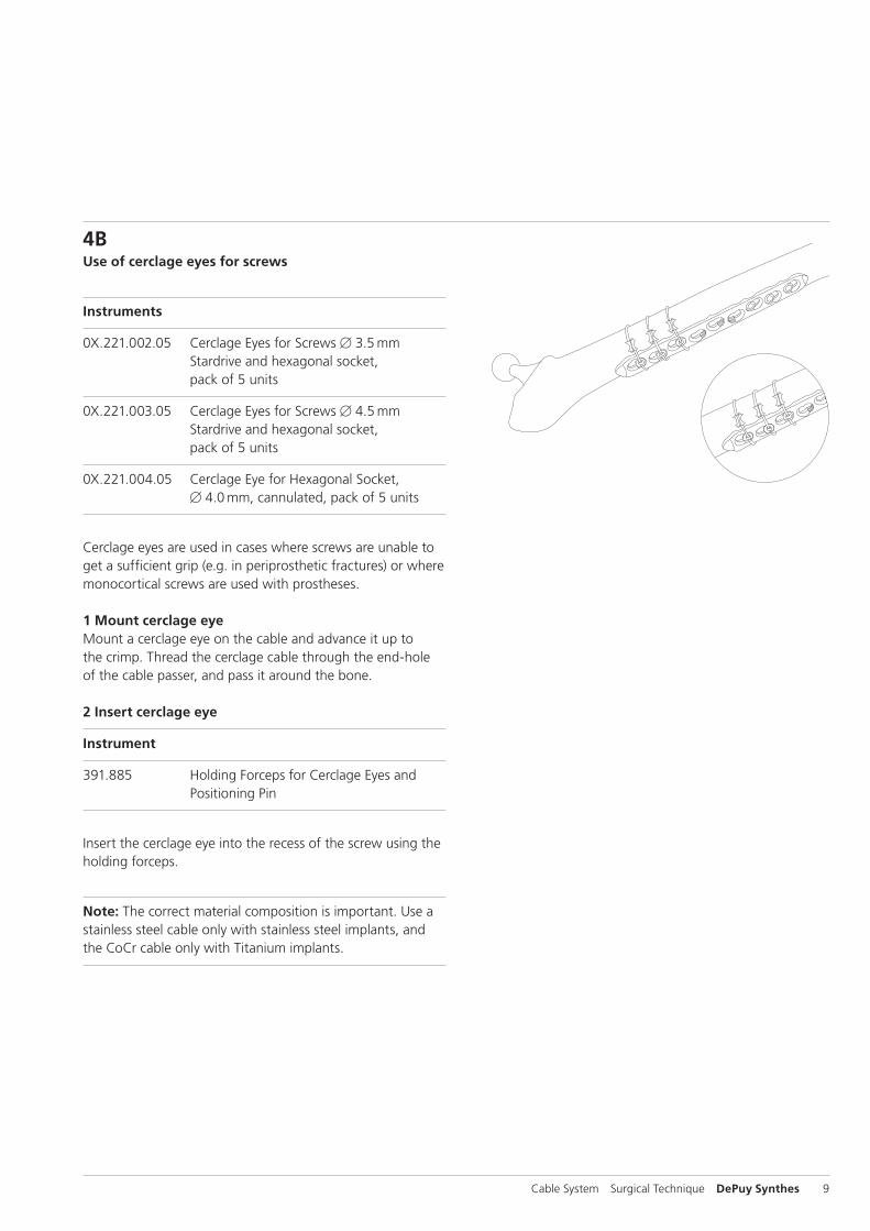
4BUse of cerclage eyes for screws
Instruments
0X.221.002.05 Cerclage Eyes for Screws B 3.5 mm Stardrive and hexagonal socket, pack of 5 units
0X.221.003.05 Cerclage Eyes for Screws B 4.5 mm Stardrive and hexagonal socket, pack of 5 units
0X.221.004.05 Cerclage Eye for Hexagonal Socket, B 4.0 mm, cannulated, pack of 5 units
Cerclage eyes are used in cases where screws are unable to get a sufficient grip (e.g. in periprosthetic fractures) or where monocortical screws are used with prostheses.
1 Mount cerclage eyeMount a cerclage eye on the cable and advance it up to the crimp. Thread the cerclage cable through the end-hole of the cable passer, and pass it around the bone.
2 Insert cerclage eye
Instrument
391.885 Holding Forceps for Cerclage Eyes and Positioning Pin
Insert the cerclage eye into the recess of the screw using the holding forceps.
Note: The correct material composition is important. Use a stainless steel cable only with stainless steel implants, and the CoCr cable only with Titanium implants.

10 DePuy Synthes Cable System Surgical Technique
Standard Cerclage Technique
4CUse of threaded cerclage positioning pins for LCP
Instruments
X98.838.01 Positioning Pin 3.5 with thread, for LCP
X98.803.01 Positioning Pin 4.5 with thread, for LCP
Threaded cerclage positioning pins for LCP are used for LCP plates 3.5 and 4.5/5.0, where the locking screws cannot sufficiently grip. The cerclage positioning eyes guarantee the stable positioning of the cable on the plate.
1 Mount the threaded cerclage positioning pin for LCPFix the plate with LCP screws to secure the position of the plate. Define the position of the positioning pin on the plate, and manually screw in the positioning pin into the threaded part of the LCP combi-hole.
Alternative implant
X81.002 CerclageFix for LCP 4.5/5.0
Alternatively CerclageFix can be used.
2 Mount the cableThread the cable through the end-hole of the cable passer, and pass it around the bone. Then pass the cable through the hole of the cerclage positioning pin.
Note: The correct material composition is important. Use a stainless steel cable only with stainless steel implants, and the CoCr cable only with TAN implants.
40kg
50kg
30kg20kg
Cable System Surgical Technique DePuy Synthes 11
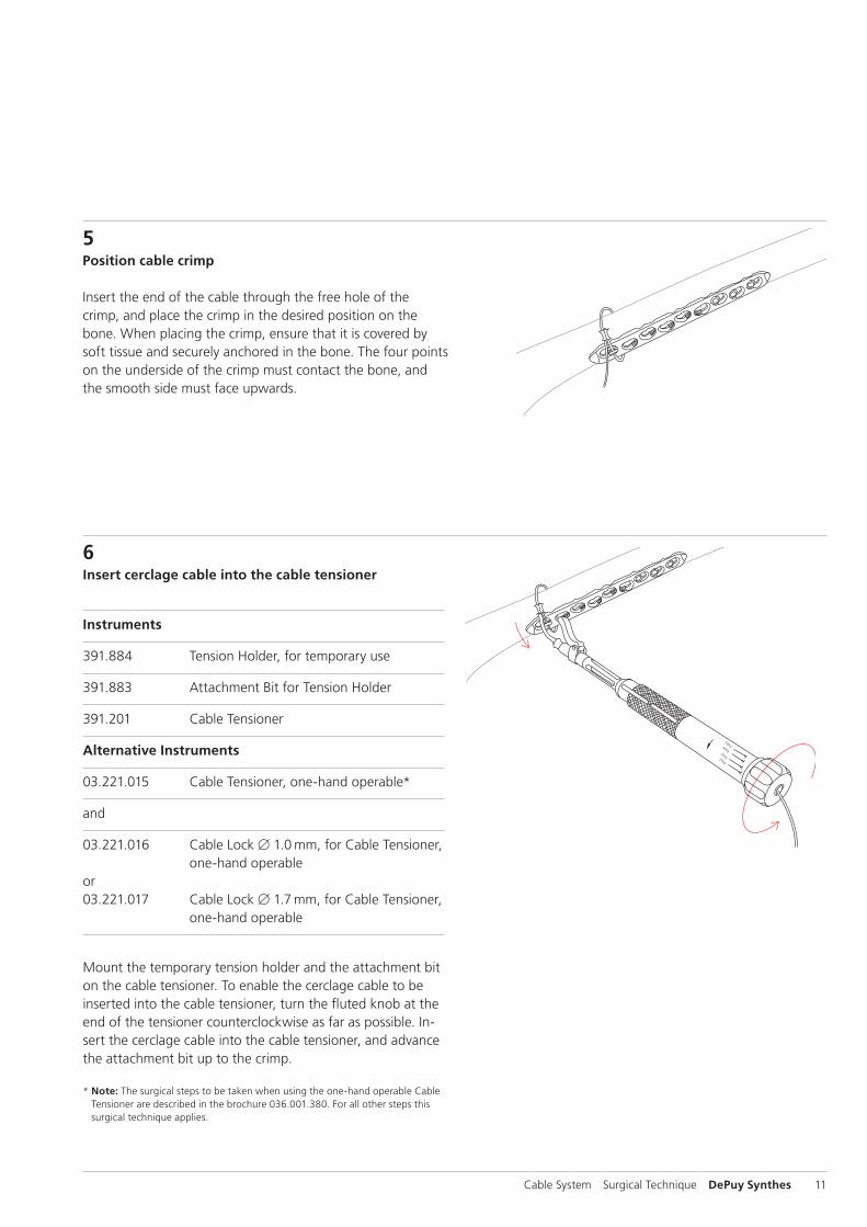
5Position cable crimp
Insert the end of the cable through the free hole of the crimp, and place the crimp in the desired position on the bone. When placing the crimp, ensure that it is covered by soft tissue and securely anchored in the bone. The four points on the underside of the crimp must contact the bone, and the smooth side must face upwards.
6Insert cerclage cable into the cable tensioner
Instruments
391.884 Tension Holder, for temporary use
391.883 Attachment Bit for Tension Holder
391.201 Cable Tensioner
Alternative Instruments
03.221.015 Cable Tensioner, one-hand operable*
and
03.221.016 Cable Lock B 1.0 mm, for Cable Tensioner, one-hand operableor03.221.017 Cable Lock B 1.7 mm, for Cable Tensioner, one-hand operable
Mount the temporary tension holder and the attachment bit on the cable tensioner. To enable the cerclage cable to be inserted into the cable tensioner, turn the fluted knob at the end of the tensioner counterclockwise as far as possible. In-sert the cerclage cable into the cable tensioner, and advance the attachment bit up to the crimp.
* Note: The surgical steps to be taken when using the one-hand operable Cable Tensioner are described in the brochure 036.001.380. For all other steps this surgical technique applies.
40kg
50kg
30kg20kg
40kg
50kg
30kg20kg
12 DePuy Synthes Cable System Surgical Technique
Standard Cerclage Technique
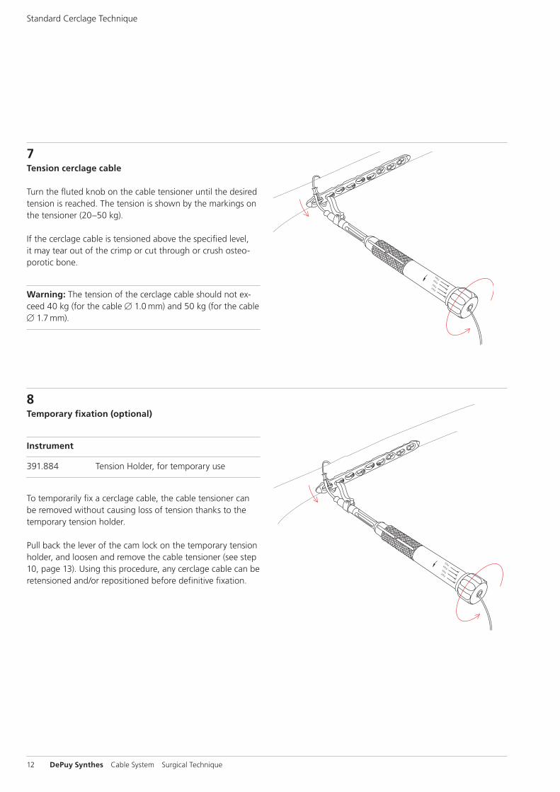
7Tension cerclage cable
Turn the fluted knob on the cable tensioner until the desired tension is reached. The tension is shown by the markings on the tensioner (20–50 kg).
If the cerclage cable is tensioned above the specified level, it may tear out of the crimp or cut through or crush osteo-porotic bone.
Warning: The tension of the cerclage cable should not ex-ceed 40 kg (for the cable B 1.0 mm) and 50 kg (for the cable B 1.7 mm).
8Temporary fixation (optional)
Instrument
391.884 Tension Holder, for temporary use
To temporarily fix a cerclage cable, the cable tensioner can be removed without causing loss of tension thanks to the temporary tension holder.
Pull back the lever of the cam lock on the temporary tension holder, and loosen and remove the cable tensioner (see step 10, page 13). Using this procedure, any cerclage cable can be retensioned and/or repositioned before definitive fixation.

Cable System Surgical Technique DePuy Synthes 13
9Secure cerclage cable with cable crimp
Instrument
391.882 Cable Crimper
When the desired cable tension is reached, the cerclage cable can be secured with the crimp. Place the jaws of the cable crimper on the crimp, ensuring that the crimp is centred and is correctly held in the crimper jaws. Pull the inner start lever first, then squeeze the outer handles to complete crimping. The toothed mechanism of the cable crimper establishes the appropriate compression pressure for securing the crimp.
Precaution: Incorrectly placing the cable crimper can lead to crimp failure.
10Remove cable tensioner
When the crimp – and thus the cerclage cable – is secured, turn the fluted knob on the cable tensioner as far as possi-ble, and remove the tensioner. If the temporary tension hold-ers are wed, push the lever of the cam lock forward, and pull the holder off the cable.

14 DePuy Synthes Cable System Surgical Technique
11Cut cable
Instrument
391.905 Cable Cutter, standard or 391.906 Cable Cutter, large
Cut the loose end of the cable using the cable cutter. Posi-tion the cutting jaws very close to the crimp, and make the cut in one action to produce a clean cut. Ensure that the adjacent cerclage cables do not get damaged.
Standard Cerclage Technique
In case the physician decides to remove the implants, implants can be removed by using general surgical instruments.
Implant Removal
O 3
Cable System Surgical Technique DePuy Synthes 15
Tension-band Technique on the Olecranon
The principle of the tension-band technique is mainly em-ployed in avulsion fractures and fractures of the olecranon or patella. Fractures or osteotomies of the greater trochanter and avulsion fractures of the medial and lateral malleolus can also be treated with this technique.
1Position patient and reduce fracture
Position the patient and reduce the fracture.
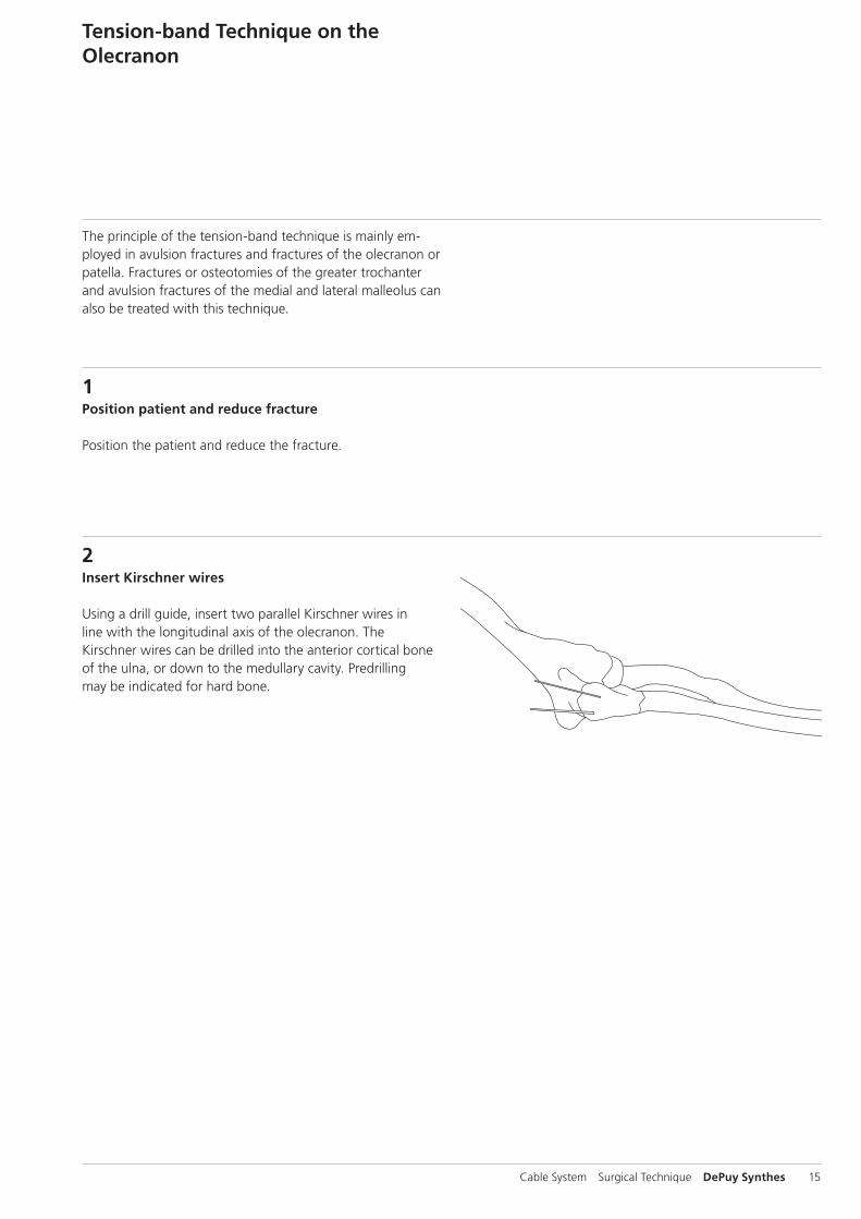
2Insert Kirschner wires
Using a drill guide, insert two parallel Kirschner wires in line with the longitudinal axis of the olecranon. The Kirschner wires can be drilled into the anterior cortical bone of the ulna, or down to the medullary cavity. Predrilling may be indicated for hard bone.

O 3O 4
A B
A=B
16 DePuy Synthes Cable System Surgical Technique
Tension-band Technique on the Olecranon
3Drill hole for cerclage cable
Instrument
310.190 Drill Bit B 2.0 mm, length 100/75 mm, 2-flute, for Quick Coupling
For the cable in the distal fragment, drill a B 2.0 mm hole perpendicular to the longitudinal axis of the ulna and distal to the fracture site. The distance between the fracture site and the drill hole (B) should match the length of the proximal fracture fragment (A). The drill must only just penetrate the second layer of cortical bone.
4Create the tension band
Instrument
X98.800.01 Cerclage Cable with Crimp B 1.0 mm
Position the crimp of the cerclage cable B 1.0 mm on the ulna parallel with its longitudinal axis. Guide the cerclage cable through the drill hole and around the Kirschner wires. Pass the free cable end across the positioned cerclage cable to produce a figure-eight loop, and insert it into the free hole of the crimp.
Alternatively, one or two screws (solid or cannulated) with cerclage eyes may be used instead of the Kirschner wires.
For tensioning, crimping and cutting of the cable, see steps 7–11 of the standard technique, page 12 ff.
Note: The correct material composition is important. Use a stainless steel cable only with stainless steel implants, and the CoCr and Titanium cable only with Titanium implants.

O 5
Cable System Surgical Technique DePuy Synthes 17
5Cut and anchor Kirschner wires
Instruments
391.820 Wire Bending Pliers, length 155 mm, for Wires up to B 1.25 mm
392.000 Bending Iron for Kirschner Wires, for Wires B 1.25 mm to 2.5 mm
Slightly retract the Kirschner wires. Cut them at an oblique angle so that the sharp ends can be bent to form small hooks using the wire bending pliers. Using the bending iron for Kirschner wires and a hammer, tap the hooks into the bone. Ensure that the hooks secure the cerclage cable.
Precaution: Do not cut the Kirschner wires with the cable cutter since this can damage the cutting edges.
In case the physician decides to remove the implants, implants can be removed by using general surgical instru-ments
Implant Removal

P 1
P 2
18 DePuy Synthes Cable System Surgical Technique
Tension-band Technique on the Patella
1Reduce fracture
Instruments
310.190 Drill Bit B 2.0 mm, length 100/75 mm, 2-flute, for Quick Coupling
X92.160 Kirschner Wire B 1.6 mm with trocar tip, length 150 mm
Tilt the distal fracture fragment to expose the fracture sur-faces of both fragments. Using the drill bit, drill two parallel holes in a retrograde direction through the proximal frag-ment. Insert the Kirschner wire into each hole with the blunt end to the fore, and advance it into the fracture surface until it emerges in front of the quadriceps. Ensure that the Kirschner wire tips remain completely in the proximal frag-ment.
Reduce the fracture using a reduction forceps with points, and secure provisionally. Check the anterior cortical bone and the articular surface to ensure that the fracture is cor-rectly reduced.
2Insert Kirschner wires into the distal fragment
Instrument
310.190 Drill Bit B 2.0 mm, length 100/75 mm, 2-flute, for Quick Coupling
Gradually insert the Kirschner wires into the distal fragment and advance at least as far as 1 cm beyond the distal pole of the patella. Check the reduction and provisional fixation.

Cable System Surgical Technique DePuy Synthes 19
3Cut the proximal ends of the Kirschner wires
Instrument
391.820 Wire Bending Pliers, length 155 mm, for Wires up to B 1.25 mm
Cut the proximal ends of the Kirschner wires at an oblique angle to produce sharp ends. Using the wire bending pliers, bend the proximal ends of the Kirschner wires to form hooks.
Precaution: Do not cut the Kirschner wires with the cable cutter since this can damage the cutting edges.
4Create the tension band
Instrument
X98.800.01 Cerclage Cable with Crimp B 1.0 mm
Position the crimp of the cerclage cable on the lateral or me-dial side, proximal to the pole of the patella. Pass the cable deep to the quadriceps and patellar tendons around the Kirschner wires. Pull the free cable end beneath the posi-tioned cable to produce a figure-eight loop, and insert it into the free hole of the crimp.
For tensioning, crimping and cutting of the cable, see steps7–11 of the standard technique, pages 12 ff.
P 4
20 DePuy Synthes Cable System Surgical Technique
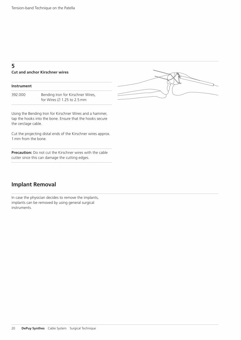
5Cut and anchor Kirschner wires
Instrument
392.000 Bending Iron for Kirschner Wires, for Wires B 1.25 to 2.5 mm
Using the Bending Iron for Kirschner Wires and a hammer, tap the hooks into the bone. Ensure that the hooks secure the cerclage cable.
Cut the projecting distal ends of the Kirschner wires approx. 1 mm from the bone.
Precaution: Do not cut the Kirschner wires with the cable cutter since this can damage the cutting edges.
Tension-band Technique on the Patella
In case the physician decides to remove the implants, implants can be removed by using general surgical instruments.
Implant Removal
Cable System Surgical Technique DePuy Synthes 21
Trochanteric Reattachment Device
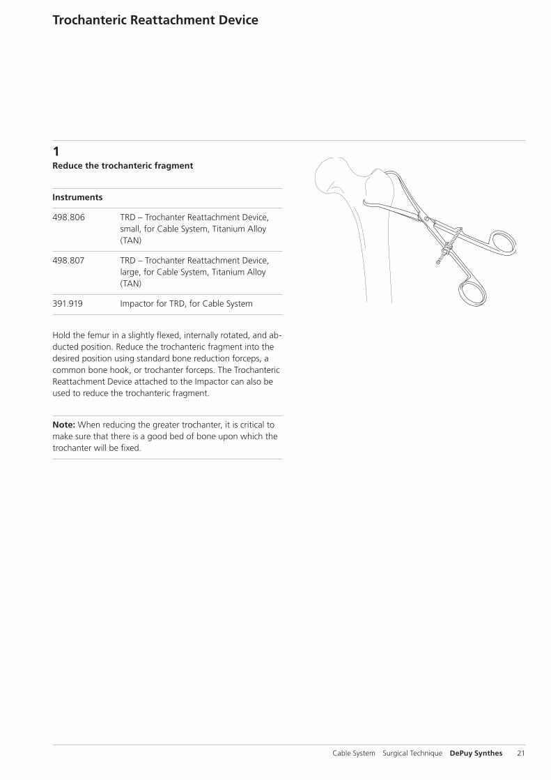
1Reduce the trochanteric fragment
Instruments
498.806 TRD – Trochanter Reattachment Device, small, for Cable System, Titanium Alloy (TAN)
498.807 TRD – Trochanter Reattachment Device, large, for Cable System, Titanium Alloy (TAN)
391.919 Impactor for TRD, for Cable System
Hold the femur in a slightly flexed, internally rotated, and ab-ducted position. Reduce the trochanteric fragment into the desired position using standard bone reduction forceps, a common bone hook, or trochanter forceps. The Trochanteric Reattachment Device attached to the Impactor can also be used to reduce the trochanteric fragment.
Note: When reducing the greater trochanter, it is critical to make sure that there is a good bed of bone upon which the trochanter will be fixed.

22 DePuy Synthes Cable System Surgical Technique
2Prepare the Trochanteric Reattachment Device (TRD)
Remove the TRD from its package and pull the free end of each cable out of it.
Note: It is very important to plan the direction from which the cables will be tensioned. If necessary, change the direc-tion in which the cables pass through the TRD to facilitate access.
To change the direction of the cables:
1 Hold the TRD in the palm of one hand, ensuring that the free ends of the cables remain in the sterile field.
2 Place one finger lengthwise over the center of the TRD (directly over the crimps) to prevent the crimps from moving.
3 Remove one cable from the TRD.
4 Thread it through the TRD and crimp in the opposite direction.
5 Repeat this process for the other cables.
Trochanteric Reattachment Device
Cable System Surgical Technique DePuy Synthes 23
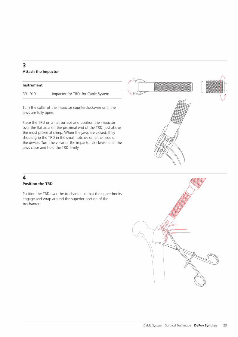
3Attach the impactor
Instrument
391.919 Impactor for TRD, for Cable System
Turn the collar of the Impactor counterclockwise until the jaws are fully open.
Place the TRD on a flat surface and position the impactor over the flat area on the proximal end of the TRD, just above the most proximal crimp. When the jaws are closed, they should grip the TRD in the small notches on either side of the device. Turn the collar of the impactor clockwise until the jaws close and hold the TRD firmly.
4Position the TRD
Position the TRD over the trochanter so that the upper hooks engage and wrap around the superior portion of the trochanter.
24 DePuy Synthes Cable System Surgical Technique
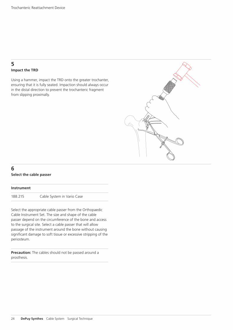
5Impact the TRD
Using a hammer, impact the TRD onto the greater trochanter, ensuring that it is fully seated. Impaction should always occur in the distal direction to prevent the trochanteric fragment from slipping proximally.
6Select the cable passer
Instrument
188.215 Cable System in Vario Case
Select the appropriate cable passer from the Orthopaedic Cable Instrument Set. The size and shape of the cable passer depend on the circumference of the bone and access to the surgical site. Select a cable passer that will allow passage of the instrument around the bone without causing significant damage to soft tissue or excessive stripping of the periosteum.
Precaution: The cables should not be passed around a prosthesis.
Trochanteric Reattachment Device
Cable System Surgical Technique DePuy Synthes 25
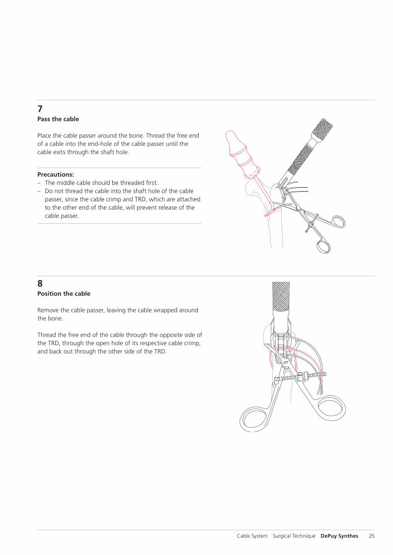
7Pass the cable
Place the cable passer around the bone. Thread the free end of a cable into the end-hole of the cable passer until the cable exits through the shaft hole.
Precautions: – The middle cable should be threaded first. – Do not thread the cable into the shaft hole of the cable
passer, since the cable crimp and TRD, which are attached to the other end of the cable, will prevent release of the cable passer.
8Position the cable
Remove the cable passer, leaving the cable wrapped around the bone.
Thread the free end of the cable through the opposite side of the TRD, through the open hole of its respective cable crimp, and back out through the other side of the TRD.
26 DePuy Synthes Cable System Surgical Technique
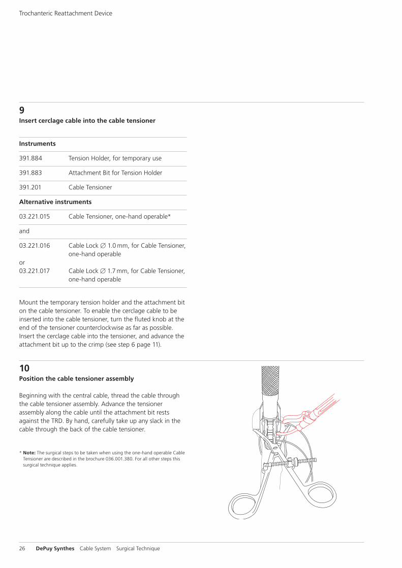
9Insert cerclage cable into the cable tensioner
Instruments
391.884 Tension Holder, for temporary use
391.883 Attachment Bit for Tension Holder
391.201 Cable Tensioner
Alternative instruments
03.221.015 Cable Tensioner, one-hand operable*
and
03.221.016 Cable Lock B 1.0 mm, for Cable Tensioner, one-hand operable
or03.221.017 Cable Lock B 1.7 mm, for Cable Tensioner,
one-hand operable
Mount the temporary tension holder and the attachment bit on the cable tensioner. To enable the cerclage cable to be inserted into the cable tensioner, turn the fluted knob at the end of the tensioner counterclockwise as far as possible. Insert the cerclage cable into the tensioner, and advance the attachment bit up to the crimp (see step 6 page 11).
10Position the cable tensioner assembly
Beginning with the central cable, thread the cable through the cable tensioner assembly. Advance the tensioner as sembly along the cable until the attachment bit rests against the TRD. By hand, carefully take up any slack in the cable through the back of the cable tensioner.
* Note: The surgical steps to be taken when using the one-hand operable Cable Tensioner are described in the brochure 036.001.380. For all other steps this surgical technique applies.
Trochanteric Reattachment Device

Cable System Surgical Technique DePuy Synthes 27
11Tension the cables
Turn the fluted knob on the tensioner until the desired tension is reached. The tension is shown by the markings on the tensioner. These lines indicate tension levels from 20 to 50 kg (see step 7 page 12).
Precaution: Take care not to exceed 50 kg of tension. Ap-plying more tension may cause the cable to cut through soft or osteoporotic bone.
12Lock tensioned cable
When the desired tension is reached, the temporary tension holder may be engaged to hold tension in the cable while additional cables are placed. Pull back the lever of the cam lock into locked position.

28 DePuy Synthes Cable System Surgical Technique
13Remove tensioner and impactor
Prior to removing the cable tensioner from the temporary tension holder, turn the fluted knob of the tensioner as far as possible.
Then remove the tensioner and the impactor from the TRD.
Note: There will be slight resistance when turning the knob for the last few turns before the tensioner is fully open. Turn the knob as far as it will go before removing the tensioner from the cable.
14Pass and tension remaining cables
Pass remaining cables following steps 6 to 8 (pages 24–25).
Tension and lock them with the temporary tension holder following steps 9 to 13 (pages 26–28).
Note: Alternatively all three cables can be passed prior to tensioning.
Trochanteric Reattachment Device

Cable System Surgical Technique DePuy Synthes 29
15Check level of tension
Check that the desired level of tension has been applied to each cable. If necessary, further tensioning may be applied to each cable prior to final crimping.
Warning: Repeated tensioning of the cable at high loads may cause fraying of the cable.
16Crimp the cables
Instrument
391.882 Cable Crimper
Place the jaws of the cable crimper over the center of the middle cable crimp, and squeeze the handles together. Use the starter handle to begin squeezing until the outer handle can be easily grasped.
The ratchet mechanism of the crimper controls the amount of deformation, thus preventing under- or overcrimping. The crimper will automatically release when the cable is crimped.
Crimp the other cables using the same procedure.
Precaution: Visually check that the cable crimp is centered and fully seated in the jaws of the crimper prior to crimping the cable. Improper placement may lead to cable slippage or crimp failure.
30 DePuy Synthes Cable System Surgical Technique
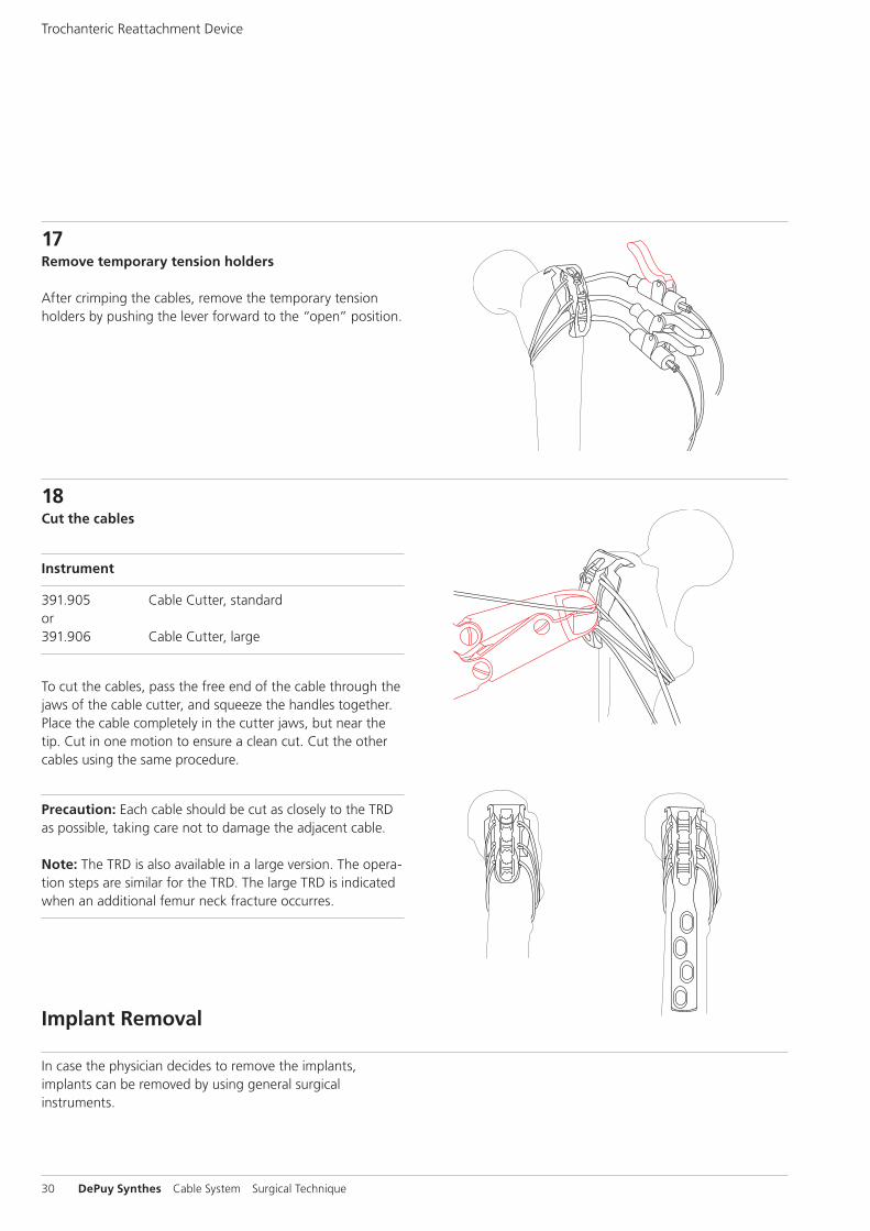
17Remove temporary tension holders
After crimping the cables, remove the temporary tension holders by pushing the lever forward to the “open” position.
18Cut the cables
Instrument
391.905 Cable Cutter, standard or391.906 Cable Cutter, large
To cut the cables, pass the free end of the cable through the jaws of the cable cutter, and squeeze the handles together. Place the cable completely in the cutter jaws, but near the tip. Cut in one motion to ensure a clean cut. Cut the other cables using the same procedure.
Precaution: Each cable should be cut as closely to the TRD as possible, taking care not to damage the adjacent cable. Note: The TRD is also available in a large version. The opera-tion steps are similar for the TRD. The large TRD is indicated when an additional femur neck fracture occurres.
Trochanteric Reattachment Device
In case the physician decides to remove the implants, implants can be removed by using general surgical instruments.
Implant Removal

Cable System Surgical Technique DePuy Synthes 31
Implants
X98.838.01 Positioning Pin 3.5 with thread, for LCPX98.838.01S Positioning Pin 3.5 with thread, for LCP,
sterile
X98.803.01 Positioning Pin 4.5 with thread, for LCPX98.803.01S Positioning Pin 4.5 with thread, for LCP,
sterile
X98.837 Cerclage Positioning Pin for LCP 3.5 and LC-DCP 3.5
X98.837S Cerclage Positioning Pin for LCP 3.5 and LC-DCP 3.5, sterile
X98.839 Cerclage Positioning Pin for LCP 4.5 and LC-DCP 4.5
X98.839S Cerclage Positioning Pin for LCP 4.5 and LC-DCP 4.5, sterile
0X.221.002.05 Cerclage Eye for Screws B 3.5 mm, Stardrive and hexagonal socket,
pack of 5 units0X.221.002S Cerclage Eye for Screws B 3.5 mm, Stardrive and hexagonal socket, sterile
0X.221.003.05 Cerclage Eye for Screws B 4.5 mm, Stardrive and hexagonal socket,
pack of 5 units0X.221.003S Cerclage Eye for Screws B 4.5 mm, Stardrive and hexagonal socket, sterile
0X.221.004.05 Cerclage Eye for Hexagonal Socket, B 4.0 mm, cannulated, pack of 5 units
0X.221.004S Cerclage Eye for Hexagonal Socket, B 4.0 mm, cannulated, sterile
X81.001 CerclageFix InsertX81.001S CerclageFix Insert, sterile
X81.002 CerclageFix for LPC 4.5/5.0X81.002S Cerclage for LCP 4.5/5.0, sterile
02.231.022 Positioning Pin for VA 5.0, cruciform, Stainless Steel
04.231.022 Positioning Pin for VA 5.0, cruciform, Pure Titanium

32 DePuy Synthes Cable System Surgical Technique
298.801.01 Cerclage Cable with Crimp B 1.7 mm, Stainless Steel
298.801.01S Cerclage Cable with Crimp B 1.7 mm, Stainless Steel, sterile
611.105.01 Cerclage Cable with Crimp B 1.7 mm, Cobalt-Chrome Alloy
611.105.01S Cerclage Cable with Crimp B 1.7 mm, Cobalt-Chrome Alloy, sterile
X98.800.01 Cerclage Cable with Crimp B 1.0 mmX98.800.01S Cerclage Cable with Crimp B 1.0 mm,
sterile
498.806* TRD – Trochanter Reattachment Device, small, for Cable System, Titanium Alloy (TAN)498.806S* TRD – Trochanter Reattachment Device, small, for Cable System, Titanium Alloy (TAN), sterile
498.807* TRD – Trochanter Reattachment Device, large, for Cable System, Titanium Alloy (TAN)498.807S* TRD – Trochanter Reattachment Device, large, for Cable System, Titanium Alloy (TAN), sterile
X=2: Stainless SteelX=4: Titanium
* TRD – Trochanter Reattachment Device: CE0086 Manufactured by: Pioneer Surgical Technology, Inc. 375 River Park Circle, Marquette MI 49855 USA Distributed by: Synthes, GmbH, Eimattstrasse 3, 4436 Oberdorf, Switzerland
Implants

Cable System Surgical Technique DePuy Synthes 33
Instruments
391.201 Cable Tensioner
03.221.015 Cable Tensioner, one-hand operable
03.221.016 Cable Lock B 1.0 mm, for Cable Tensioner, one-hand operable
03.221.017 Cable Lock B 1.7 mm, for Cable Tensioner, one-hand operable
391.883 Attachment Bit for Tension Holder
391.884 Tension Holder, for temporary use
391.882 Cable Crimper

34 DePuy Synthes Cable System Surgical Technique
391.885 Holding Forceps for Cerclage Eyes and Positioning Pin
391.905 Cable Cutter, standard
391.906 Cable Cutter, large
391.103–108 Cable Passer, available in various designs and sizes
391.919 Impactor for TRD, for Cable System
Instruments
Cable System Surgical Technique DePuy Synthes 35
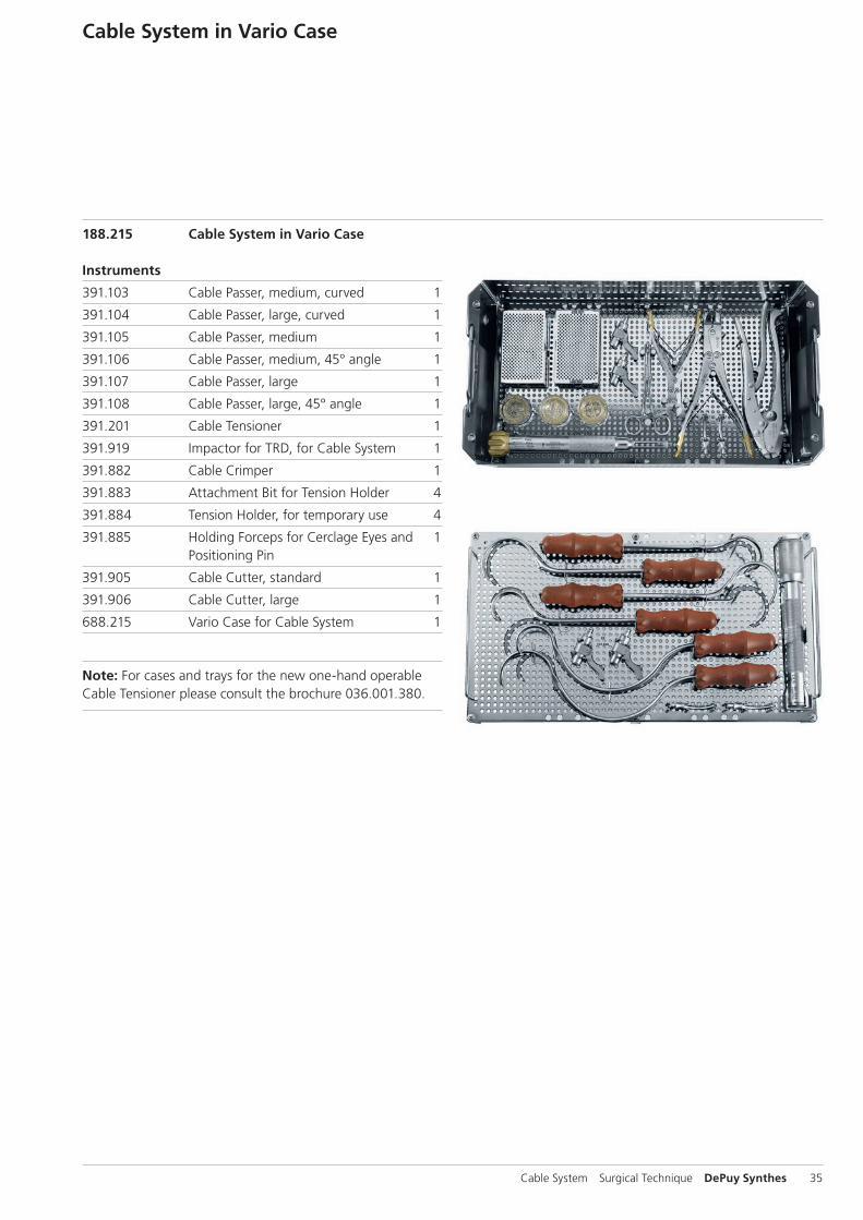
Cable System in Vario Case
188.215 Cable System in Vario Case
Instruments
391.103 Cable Passer, medium, curved 1
391.104 Cable Passer, large, curved 1
391.105 Cable Passer, medium 1
391.106 Cable Passer, medium, 45° angle 1
391.107 Cable Passer, large 1
391.108 Cable Passer, large, 45° angle 1
391.201 Cable Tensioner 1
391.919 Impactor for TRD, for Cable System 1
391.882 Cable Crimper 1
391.883 Attachment Bit for Tension Holder 4
391.884 Tension Holder, for temporary use 4
391.885 Holding Forceps for Cerclage Eyes and 1 Positioning Pin
391.905 Cable Cutter, standard 1
391.906 Cable Cutter, large 1
688.215 Vario Case for Cable System 1
Note: For cases and trays for the new one-hand operable Cable Tensioner please consult the brochure 036.001.380.

36 DePuy Synthes Cable System Surgical Technique
MRI Information
Torque, Displacement and Image Artifacts according to ASTM F 2213-06, ASTM F 2052-06e1 and ASTM F2119-07Non-clinical testing of worst case scenario in a 3 T MRI system did not reveal any relevant torque or displacement of the construct for an experimentally measured local spatial gradient of the magnetic field of 3.69 T/m. The largest image artifact extended approximately 169 mm from the construct when scanned using the Gradient Echo (GE). Testing was conducted on a 3 T MRI system.
Radio-Frequency-(RF-)induced heating according to ASTM F2182-11aNon-clinical electromagnetic and thermal testing of worst case scenario lead to peak temperature rise of 9.5 °C with an average temperature rise of 6.6 °C (1.5 T) and a peak temperature rise of 5.9 °C (3 T) under MRI Conditions using RF Coils (whole body averaged specific absorption rate [SAR] of 2 W/kg for 6 minutes [1.5 T] and for 15 minutes [3 T]).
Precautions: The above mentioned test relies on non-clin-ical testing. The actual temperature rise in the patient will depend on a variety of factors beyond the SAR and time of RF application. Thus, it is recommended to pay particular attention to the following points: – It is recommended to thoroughly monitor patients under-
going MR scanning for perceived temperature and/or pain sensations.
– Patients with impaired thermoregulation or temperature sensation should be excluded from MR scanning proce-dures.
– Generally, it is recommended to use a MR system with low field strength in the presence of conductive implants. The employed specific absorption rate (SAR) should be reduced as far as possible.
– Using the ventilation system may further contribute to reduce temperature increase in the body.


0123
Synthes GmbHEimattstrasse 34436 OberdorfSwitzerlandTel: +41 61 965 61 11Fax: +41 61 965 66 00www.depuysynthes.com
Not all products are currently available in all markets.
This publication is not intended for distribution in the USA.
All surgical techniques are available as PDF files at www.depuysynthes.com/ifu ©
DeP
uy S
ynth
es T
raum
a, a
div
isio
n of
Syn
thes
Gm
bH. 2
016.
A
ll rig
hts
rese
rved
. 03
6.0
00.
371
DSE
M/T
RM
/061
5/03
98(2
) 09
/16