Surge Wave Receiver digiPHONE
29
1 User Manual Surge Wave Receiver digiPHONE + Issue 1 (04/2011) - ENG Mess- und Ortungstechnik Measuring and Locating Technologies Elektrizitätsnetze Power Networks Kommunikationsnetze Communication Networks Rohrleitungsnetze Water Networks Leitungsortung Line Locating
Transcript of Surge Wave Receiver digiPHONE

1
User Manual
Surge Wave Receiver
digiPHONE+
Issue 1 (04/2011) - ENG
Mess- und Ortungstechnik
Measuring and Locating Technologies
Elektrizitätsnetze
Power Networks
Kommunikationsnetze
Communication Networks
Rohrleitungsnetze
Water Networks
Leitungsortung
Line Locating

2

Consultation with SebaKMT
3
Consultation with SebaKMT
The present system manual has been designed as an operating guide and for reference. It is meant to answer your questions and solve your problems in as fast and easy a way as possible. Please start with referring to this manual should any trouble occur.
In doing so, make use of the table of contents and read the relevant paragraph with great attention. Furthermore, check all terminals and connections of the instruments involved.
Should any question remain unanswered, please contact:
Seba Dynatronic
Mess- und Ortungstechnik GmbH
Hagenuk KMT
Kabelmesstechnik GmbH
Dr.-Herbert-Iann-Str. 6 D - 96148 Baunach
Phone: +49 / 9544 / 68 – 0 Fax: +49 / 9544 / 22 73
Röderaue 41 D - 01471 Radeburg / Dresden
Phone: +49 / 35208 / 84 – 0 Fax: +49 / 35208 / 84 249
E-Mail: [email protected] http://www.sebakmt.com
SebaKMT
All rights reserved. No part of this handbook may be copied by photographic or other means unless SebaKMT have before-hand declared their consent in writing. The content of this handbook is subject to change without notice. SebaKMT cannot be made liable for technical or printing errors or shortcomings of this handbook. SebaKMT also disclaim all responsibility for damage resulting directly or indirectly from the delivery, supply, or use of this matter.

Terms of Warranty
4
Terms of Warranty
SebaKMT accept responsibility for a claim under warranty brought forward by a customer for a product sold by SebaKMT under the terms stated below.
SebaKMT warrant that at the time of delivery SebaKMT products are free from manufacturing or material defects which might considerably reduce their value or usability. This warranty does not apply to faults in the software supplied. During the period of warranty, SebaKMT agree to repair faulty parts or replace them with new parts or parts as new (with the same usability and life as new parts) according to their choice.
SebaKMT reject all further claims under warranty, in particular those from consequential damage. Each component and product replaced in accordance with this warranty becomes the property of SebaKMT.
All warranty claims versus SebaKMT are hereby limited to a period of 12 months from the date of delivery. Each component supplied by SebaKMT within the context of warranty will also be covered by this warranty for the remaining period of time but for 90 days at least.
Each measure to remedy a claim under warranty shall exclusively be carried out by SebaKMT or an authorized service station.
To register a claim under the provisions of this warranty, the customer has to complain about the defect, in case of an immediately detectable fault within 10 days from the date of delivery.
This warranty does not apply to any fault or damage caused by exposing a product to conditions not in accordance with this specification, by storing, transporting, or using it improperly, or having it serviced or installed by a workshop not authorized by SebaKMT. All responsibility is disclaimed for damage due to wear, will of God, or connection to foreign components.
For damage resulting from a violation of their duty to repair or re-supply items, SebaKMT can be made liable only in case of severe negligence or intention. Any liability for slight negligence is disclaimed.
Contents
5
Contents
Consultation with SebaKMT ........................................................................................... 3
Terms of Warranty ........................................................................................................... 4
Contents ........................................................................................................................... 5
1 Safety Advices .................................................................................................. 6
2 Technical Description ...................................................................................... 7
2.1 System Description ............................................................................................ 7
2.2 Technical Data ................................................................................................... 8
2.3 Connections and Controls on the Indicator Unit ................................................ 9
3 Operation ........................................................................................................ 10
3.1 Starting Up the digiPHONE+............................................................................. 10
3.1.1 Preparing the Sensor ....................................................................................... 10
3.1.2 Connecting the Sensor and Headphones to the Indicator Unit ........................ 12
3.1.3 Starting Up the Indicator Unit ........................................................................... 13
3.1.4 Configuring the Device ..................................................................................... 16
3.2 Starting Up the Surge Wave Generator ........................................................... 17
3.3 Pinpointing Cable Faults .................................................................................. 18
3.3.1 Tracking the Cable ........................................................................................... 18
3.3.2 Approaching the Fault ...................................................................................... 20
3.3.2.1 General Notes .................................................................................................. 20
3.3.2.2 Adjusting the Measurement Settings ............................................................... 22
3.3.2.3 Procedure ......................................................................................................... 25
3.4 Shutting Down the digiPHONE+ ....................................................................... 27
4 Storage and Transport ................................................................................... 28
5 Maintenance and Care ................................................................................... 29

Safety Advices
6
1 Safety Advices
This manual contains basic instructions on commissioning and operating the digiPHONE
+. For this reason, it is important to ensure that the manual is available at all
times to authorised and trained personnel. Any personnel who will be using the devices should read the manual thoroughly. The manufacturer will not be held liable for any injury or damage to personnel or property through failure to observe the safety precautions contained in this handbook.
Locally applying regulations have to be observed.
Important instructions concerning personal, operational and technical safety are marked in the text as follows:
Symbol Description
WARNING
Indicates a potential danger that may lead to fatal or serious injury.
CAUTION
Indicates a potentially hazardous situation which, if not avoided, may result in minor or moderate injury or material damage.
The notes contain important information and useful tips for using the system. Failure to observe them can render the measuring results useless.
Useful tips from practical experience.
It is important to observe the general electrical regulations of the country in which the device will be installed and operated, as well as the current national accident prevention regulations and internal company rules (work, operating and safety regulations).
Use genuine accessories to ensure system safety and reliable operation. The use of other parts is not permitted and invalidates the warranty.
This system and its peripheral equipment may only be operated by trained or instructed personnel. Anyone else must be kept away.
The system may only be installed by an authorised electrician. DIN VDE 0104 (EN 50191), DIN VDE 0105 (EN 50110) and the German accident prevention regulations (UVV) define an electrician as someone whose knowledge, experience and familiarity with the applicable regulations enables him to recognise potential hazards.
Repairs and service must only be done by SebaKMT or authorised service departments of SebaKMT. SebaKMT recommends having the equipment serviced and checked once per year at a SebaKMT service location.
SebaKMT also offers direct on-site support. Please contact our service office for more information.
Safety precautions
Labelling of safety instructions
Working with products from SebaKMT
Operating staff
Repair and maintenance
Technical Description
7
2 Technical Description
2.1 System Description
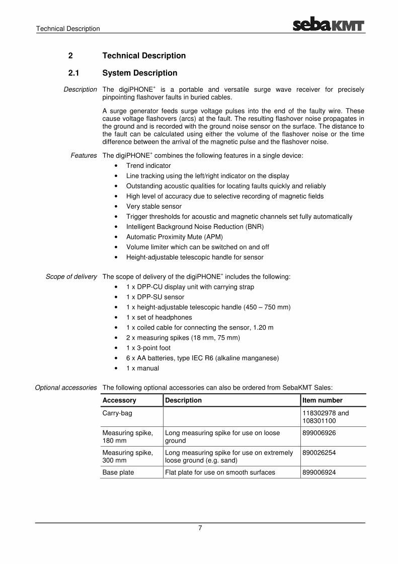
The digiPHONE+ is a portable and versatile surge wave receiver for precisely
pinpointing flashover faults in buried cables.
A surge generator feeds surge voltage pulses into the end of the faulty wire. These cause voltage flashovers (arcs) at the fault. The resulting flashover noise propagates in the ground and is recorded with the ground noise sensor on the surface. The distance to the fault can be calculated using either the volume of the flashover noise or the time difference between the arrival of the magnetic pulse and the flashover noise.
The digiPHONE+ combines the following features in a single device:
• Trend indicator
• Line tracking using the left/right indicator on the display
• Outstanding acoustic qualities for locating faults quickly and reliably
• High level of accuracy due to selective recording of magnetic fields
• Very stable sensor
• Trigger thresholds for acoustic and magnetic channels set fully automatically
• Intelligent Background Noise Reduction (BNR)
• Automatic Proximity Mute (APM)
• Volume limiter which can be switched on and off
• Height-adjustable telescopic handle for sensor
The scope of delivery of the digiPHONE+ includes the following:
• 1 x DPP-CU display unit with carrying strap
• 1 x DPP-SU sensor
• 1 x height-adjustable telescopic handle (450 – 750 mm)
• 1 x set of headphones
• 1 x coiled cable for connecting the sensor, 1.20 m
• 2 x measuring spikes (18 mm, 75 mm)
• 1 x 3-point foot
• 6 x AA batteries, type IEC R6 (alkaline manganese)
• 1 x manual
The following optional accessories can also be ordered from SebaKMT Sales:
Accessory Description Item number
Carry-bag 118302978 and 108301100
Measuring spike, 180 mm
Long measuring spike for use on loose ground
899006926
Measuring spike, 300 mm
Long measuring spike for use on extremely loose ground (e.g. sand)
890026254
Base plate Flat plate for use on smooth surfaces 899006924
Description
Features
Scope of delivery
Optional accessories

Technical Description
8
2.2 Technical Data
The digiPHONE+ has the following parameters:
Parameter Value
Acoustic amplification >120 dB (facility for limiting amplification to 84 dB(A) can be switched on and off)
Dynamic range of the sensor
• Acoustic channel
• Magnetic channel
>110 dB
>110 dB
Frequency range of sensor 100 to 1,500 Hz
Filter stages
• Without filter
• Low pass
• Band pass
• High pass
100 to 1,500 Hz
100 to 400 Hz
150 to 600 Hz
200 to 1,500 Hz
Power supply
• Batteries
6 x AA batteries, type IEC R6 (alkaline manganese)
Operating time
• Batteries
>10 hours
Operating temperature -20°C to 55°C
Operating humidity Max. relative humidity 93% at 30°C
Storage temperature -30°C to 70°C
Display TFT colour display with 320 x 240 pixels
Weight
• Indicator unit
• Sensor (incl. telescopic handle)
<0.9 kg
<2.2 kg
Dimensions
• Indicator unit
• Sensor
225 mm x 65 mm x 100 mm (W x H x D)
230 mm x 140 mm (Ø x H)
Protection rating
• Indicator unit
• Sensor (incl. bar)
(according to IEC 60529 (DIN VDE 0470-1))
IP 54
IP 65 (only for plugged-in connector)

Technical Description
2.3 Connections and Controls on the Indicator Unit
The following illustration shows the connections and controls on the digiPHONEindicator unit:
Element Description
Display
Knob
Indicator unit on/off (when pressed for long time)
Backlight on/off (when pressed for short time)
LED for
Mute on/off
Connection socket for sensor
Connection socket for headphones
9
Connections and Controls on the Indicator Unit
The following illustration shows the connections and controls on the digiPHONE
Description
Display
Knob
Indicator unit on/off (when pressed for long time)
Backlight on/off (when pressed for short time)
LED for indicating the charge state (only for built-in rechargeable battery)
Mute on/off
Connection socket for sensor
Connection socket for headphones
The following illustration shows the connections and controls on the digiPHONE+
in rechargeable battery)

Operation
10
3 Operation
3.1 Starting Up the digiPHONE+
3.1.1 Preparing the Sensor
Three different probes are supplied with the sensor as standard (two sensor rods and one 3-point foot). They can be screwed onto the underside of the sensor to suit the ground conditions.
The 18 mm rod and the 3-point foot can both be used on smooth and solid ground. Because their acoustic qualities are different, it is for the operator to decide which probe they prefer to use on such ground.
An advantage of the 3-point foot is that a sensor rod can be fitted on its underside. This means that the foot does not need to be constantly unscrewed when the ground changes.
Fitting a suitable probe on the sensor
3-point foot
preferred for uneven, solid ground
Sensor rod 75 mm
preferred for grassland and loose ground
Sensor rod 18 mm
preferred for smooth, solid ground (e.g. asphalt)

Operation
11
This is how to attach the telescopic bar to the sensor:
This is how to adjust the height of the telescopic handle:
Attaching the telescopic handle to
the sensor
Adjusting the height of the telescopic handle

3.1.2 Connecting the Sensor and Headphones to the Indicator Unit
The headphones are connected to the black socket
plug is inserted, the white markings on the plug and socket must line up. Theslot into place and must not be turned!
The coiled cable supplied is used to connect the sensor. Because the plug type and pin configuration match at both ends of the cable, you can choose any cable alignment.
One end of the cable is connected
end to the socket on the top of the sensor (see illustration). The plug is aligned by the guides on the plug and the grooves on the socket. You must hear and feel the plug engage.
Connection cable tothe indicator unit
12
Connecting the Sensor and Headphones to the Indicator Unit
The headphones are connected to the black socket on the indicator unit. When the
plug is inserted, the white markings on the plug and socket must line up. Theslot into place and must not be turned!
The coiled cable supplied is used to connect the sensor. Because the plug type and pin configuration match at both ends of the cable, you can choose any cable alignment.
One end of the cable is connected to the socket on the indicator unit and the other
end to the socket on the top of the sensor (see illustration). The plug is aligned by the guides on the plug and the grooves on the socket. You must hear and feel the plug
Connection cable to the indicator unit
Operation
Connecting the Sensor and Headphones to the Indicator Unit
on the indicator unit. When the
plug is inserted, the white markings on the plug and socket must line up. The plug has to
The coiled cable supplied is used to connect the sensor. Because the plug type and pin configuration match at both ends of the cable, you can choose any cable alignment.
on the indicator unit and the other
end to the socket on the top of the sensor (see illustration). The plug is aligned by the guides on the plug and the grooves on the socket. You must hear and feel the plug
Ventilation valve
Do not open with force!

Operation
13
3.1.3 Starting Up the Indicator Unit
The indicator unit can be switched on by briefly pressing the button. The device is
ready for use after just a few seconds and the measurement screen is shown.
If the locator is not used for 10 minutes (this includes touching the sensor or telescopic handle), it switches off automatically.
After switching on the device, you should check the battery status immediately using the charging bar in the top right corner of the display. If the bar is almost empty, we recommend that you take spare batteries with you or charge up the indicator unit beforehand (if it is equipped with the built-in rechargeable battery).
For devices with the optional built-in battery, this rechargeable battery is always used up first and then the normal batteries (if fitted).
This produces a maximum operating time of over 20 hours.
The backlight of the display is automatically activated straight after the indicator unit is switched on. Because the unit has a transflective display, when there is enough sunlight
you should turn off the backlight by briefly pressing the button. This extends the
operating time of the indicator unit.
The backlight can be switched back on at any time by briefly pressing the button again.
Apart from a few functions (backlight, headphone mode), the indicator unit is operated solely using the knob. The functions available vary according to the current view:
Action Function in the measurement screen
Function in the menu screen
Opens the menu screen Opens the currently selected menu
item
Adjusts the volume (acoustic amplification)
Selects the menu item
Switching on the indicator unit
Battery test
Backlight
Operation using the knob

Operation
14
You can switch from the measurement screen to the menu screen at any time and change any settings in two steps at most:
Menu structure
Measurement screen Menu screens

Operation
15
Each menu screen is made up as follows:
In addition to the acoustic signal in the headphones, the measurement screen shows all relevant information that may be useful when approaching the cable fault during the pinpointing procedure:
Layout of the menu screens
Layout of the measurement screen
Currently selected menu item
Description of the currently selected
menu item
Active function Non-active function
Current menu level
Return to the measurement
screen Setup
Volume / amplification
settings Current filter setting
Status of background noise
reduction Battery status
Current time difference
Time difference of the last position
Line position Fault direction
Indicator for arrival of a magnetic pulse
Bar graph for magnetic pulse (with numeric instantaneous value,
maximum marker and numeric range limits)
Indicator for arrival of an acoustic signal

3.1.4 Configuring the Device
After the indicator unit has been switched on, you can adjust the basic settings. To do
so, switch to the
The following menu then
In this menu you can perform the following basic settings:
Menu item
Description
Sets the display language.
Sets the measuring unit.
The time difference between the arrival of the magnetic pulse and the flashover
noise milliseconds
Activates/deactivates Automatic
If this function is activated, the headphones are muted as soon as the operator touches the sensor’s telescopic handle with their hand. This protects the operator from excessively loud background noise which often occurs when the sensor is moved.
Alternatively, muting or unmuting can also be activated manually at any time
using the
Activates/deactivates the
When the fault direction indicator is activated, an the displayfrom the fault.
Restores the factory settings.
16
Configuring the Device
After the indicator unit has been switched on, you can adjust the basic settings. To do
so, switch to the menu screen by pressing the knob and selecting the menu item
The following menu then appears in the display:
In this menu you can perform the following basic settings:
Description
Sets the display language.
Sets the measuring unit.
The time difference between the arrival of the magnetic pulse and the flashover
noise − i.e. the distance to the fault − can be shown either directly (in milliseconds) or converted into a unit of length (metres
To convert time to distance a constant (mean) propagation speed is taken as the basis. However, because the actual grouhence the sound propagation speed vary greatly, the distances calculated can also differ from the real values to various degrees. The distances displayed can therefore only be considered as guides!
Activates/deactivates Automatic Proximity Mute (APM).
If this function is activated, the headphones are muted as soon as the operator touches the sensor’s telescopic handle with their hand. This protects the operator from excessively loud background noise which often occurs when the
or is moved.
Alternatively, muting or unmuting can also be activated manually at any time
using the button (see page 21).
Activates/deactivates the fault direction indicator.
When the fault direction indicator is activated, an additional direction arrow in the display (see page 20) signals whether the user has moved tfrom the fault.
Restores the factory settings.
Operation
After the indicator unit has been switched on, you can adjust the basic settings. To do
by pressing the knob and selecting the menu item .
The time difference between the arrival of the magnetic pulse and the flashover
can be shown either directly (in metres or feet).
To convert time to distance a constant (mean) propagation speed is taken as the basis. However, because the actual ground conditions and hence the sound propagation speed vary greatly, the distances calculated can also differ from the real values to various degrees. The distances displayed can therefore only be considered as guides!
Proximity Mute (APM).
If this function is activated, the headphones are muted as soon as the operator touches the sensor’s telescopic handle with their hand. This protects the operator from excessively loud background noise which often occurs when the
Alternatively, muting or unmuting can also be activated manually at any time
additional direction arrow in ) signals whether the user has moved towards or away
Operation
17
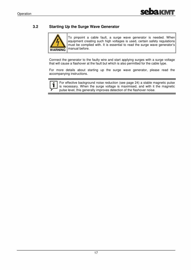
3.2 Starting Up the Surge Wave Generator
WARNING
To pinpoint a cable fault, a surge wave generator is needed. When equipment creating such high voltages is used, certain safety regulations must be complied with. It is essential to read the surge wave generator’s manual before.
Connect the generator to the faulty wire and start applying surges with a surge voltage that will cause a flashover at the fault but which is also permitted for the cable type.
For more details about starting up the surge wave generator, please read the accompanying instructions.
For effective background noise reduction (see page 24) a stable magnetic pulse is necessary. When the surge voltage is maximised, and with it the magnetic pulse level, this generally improves detection of the flashover noise.

Operation
18
3.3 Pinpointing Cable Faults
CAUTION
If the volume limiter is deactivated, when listening to flashover noise, additional airborne sound and excessive amplification can lead to dangerous sound levels in the headphones!
3.3.1 Tracking the Cable
After prelocation, it is usually relatively easy to narrow down where the fault lies in the cable.
If, however, the area is large because the cable plans are inaccurate, we recommend that you track the cable with a line location device before pinpointing, and mark its route.
On the other hand, if the area for pinpointing is not too large, all you normally need to do is find a starting position with the digiPHONE
+ directly over the cable and start
pinpointing from here. Please proceed as follows:
Step Action
1 Place the sensor on the ground with the arrow pointing in the direction where you believe the cable to be running.
2 Wait until the indicator unit signals the arrival of the magnetic pulse.
3 Turn the sensor a little on its own axis and stay in this position until the next pulse is recorded.
Using the maximum marker and the numeric level indicator, check whether the field strength is stronger or weaker with this alignment.
Indicates that a magnetic pulse has arrived
Field strength of the magnetic pulse
Maximum marker

Operation
19
Step Action
4 Look for the position with the maximum field strength by turning the sensor slowly in time with the pulses.
In this position, the arrow on the sensor casing points along the route of the cable.
5 Keep the sensor aligned this way and observe the line position indicator. This could show the following:
The sensor is to the right of the cable
The sensor is over the cable
The sensor is to the left of the cable
6 Move the sensor sideways in time with the pulses (crosswise to the cable route) until the indicator shows that it is exactly over the cable. This is the starting position for pinpointing.
Actual cable route

3.3.2 Approaching the Fault
3.3.2.1 General Notes
When pinpointing a cable fault with the digiPHONEthe surge pulse and the flashover noise are evaluated.
The display on the indicator unit signals when a pulse arrives (the magnetic trigger
symbol light up) which helps to discern the flashover noise from the background
noise in the headphones. The “coincidence” of these events enables the user to correctly identify the flashover noise when it occurs at the same time as the magnetic pulse. The volume of the flashover noise normally continues to rise as you near the fault.
Another indicator for the distance to the fault is the transit time difference between tmagnetic pulse and the acoustic flashover signal which is shown permanently on the display.
The cause of this difference is the varying propagation speed of the two signals in the ground. The magnetic field spreads at about the speed of light, whereas tspeed of the flashover noise is considerably less and varies according to the ground conditions. As you approach the fault the transit time difference decreases
The direction indicator, which can be enablthe device settingsfrom the fault. This message results from a comparison difference of the previous position and the current time difference. The direction indicator can have the following states:
No message
In the previous position a transit time difference and therefore a comparative
value could not be measured
When pinpointing faults using the direction indicator, you must forwardsdirection indicator tells you to turn round, you must indeed turn 180° along with the sensor!
Technical principles
How to read the direction indicator
20
Approaching the Fault
General Notes
When pinpointing a cable fault with the digiPHONE+, both the magnetic field created by
the surge pulse and the flashover noise are evaluated.
The display on the indicator unit signals when a pulse arrives (the magnetic trigger
light up) which helps to discern the flashover noise from the background
noise in the headphones. The “coincidence” of these events enables the user to identify the flashover noise when it occurs at the same time as the magnetic
The volume of the flashover noise normally continues to rise as you near
Another indicator for the distance to the fault is the transit time difference between tmagnetic pulse and the acoustic flashover signal which is shown permanently on the
The cause of this difference is the varying propagation speed of the two signals in the ground. The magnetic field spreads at about the speed of light, whereas tspeed of the flashover noise is considerably less and varies according to the ground
As you approach the fault the transit time difference decreases
The direction indicator, which can be enabled or disabled through the device settings (see page 16), shows whether the user has moved towards or away
from the fault. This message results from a comparison between the last measured time difference of the previous position and the current time difference. The direction indicator can have the following states:
No message Closer to the fault Further from the fault
In the previous position a difference and
therefore a comparative value could not be
measured
The last change in position decreased the distance to
the fault
The last change in position increased the distance to
When pinpointing faults using the direction indicator, you must forwards with the sensor (in the direction of the arrow on the sensor). If the direction indicator tells you to turn round, you must indeed turn 180° along with the sensor!
Operation
, both the magnetic field created by
The display on the indicator unit signals when a pulse arrives (the magnetic trigger
light up) which helps to discern the flashover noise from the background
noise in the headphones. The “coincidence” of these events enables the user to identify the flashover noise when it occurs at the same time as the magnetic
The volume of the flashover noise normally continues to rise as you near
Another indicator for the distance to the fault is the transit time difference between the magnetic pulse and the acoustic flashover signal which is shown permanently on the
The cause of this difference is the varying propagation speed of the two signals in the ground. The magnetic field spreads at about the speed of light, whereas the propagation speed of the flashover noise is considerably less and varies according to the ground
As you approach the fault the transit time difference decreases.
ed or disabled through the menu item in ), shows whether the user has moved towards or away
between the last measured time difference of the previous position and the current time difference. The direction
Further from the fault
The last change in position increased the distance to
the fault
When pinpointing faults using the direction indicator, you must always move with the sensor (in the direction of the arrow on the sensor). If the
direction indicator tells you to turn round, you must indeed turn 180° along with

Operation
To protect the operator’s hearing from excessive sound levels, the volume regulator on the digiPHONE
The volume is regulated in the
The device settings can limit the maximum sound levemenu item (see next page)
The headphones can be muted at any time with the
by pressing the button again or increasing the volume.
Furthermore, the Automatic Proximity Mute (APM) featureas soon as your hand touches the telescopic handle. In this mode, manual switching
can of course also be performed using the
sequence is as follows:
Hand on the handle
Hand off the handle
Volume setting
Muting
21
To protect the operator’s hearing from excessive sound levels, the volume regulator on the digiPHONE
+ has a number of protective mechanisms.
The volume is regulated in the measurement screen by turning the knob.
The device settings can limit the maximum sound level to 84 dB(A)menu item (see next page).
The headphones can be muted at any time with the button. Muting is switched
by pressing the button again or increasing the volume.
Furthermore, the menu item in the device settings can be used to Automatic Proximity Mute (APM) feature (see page 16). When enabled, muting occurs as soon as your hand touches the telescopic handle. In this mode, manual switching
can of course also be performed using the button. With APM enabled
sequence is as follows:
Hand on the handle
Hand off the handle
Louder Quieter
To protect the operator’s hearing from excessive sound levels, the volume regulator on
by turning the knob.
l to 84 dB(A) through the
button. Muting is switched off
menu item in the device settings can be used to activate the ). When enabled, muting occurs
as soon as your hand touches the telescopic handle. In this mode, manual switching
With APM enabled the

3.3.2.2 Adjusting the Measurement Settings
By pressing the knob, you can at any time switch from the menu screen
In this menu you can perform the
Menu item
Description
BNR Activates/deactivates Background Noise Reduction (BNR).
Background noise reduction is used to make it easier to detect acoustic pulses in environments with a lot of interference. Often it is not background noise caused by rain or traffic, for example, from the actual signal and this makes acoustic pinpointing more difficult.
Activates/deactivates the volume limiter.
If this function is activated, the volume is limited to
Filter settings (see next page)
22
Adjusting the Measurement Settings
By pressing the knob, you can at any time switch from the measurement screen with the most important measurement settings:
In this menu you can perform the following measurement settings:
Description
Activates/deactivates Background Noise Reduction (BNR).
Background noise reduction is used to make it easier to detect acoustic pulses in environments with a lot of interference. Often it is not background noise caused by rain or traffic, for example, from the actual signal and this makes acoustic pinpointing more difficult.
Activates/deactivates the volume limiter.
If this function is activated, the volume is limited to a maximum of 84
When the volume limiter is being used, acoustic amplification should not be set too high!
Excessive amplification, requiring the automatic limiter to constantly intervene, will attenuate the flashover noise. The background noise,the other hand, would become more dominant as it is also amplified.
Filter settings (see next page)
Operation
measurement screen to the
following measurement settings:
Activates/deactivates Background Noise Reduction (BNR).
Background noise reduction is used to make it easier to detect acoustic pulses in environments with a lot of interference. Often it is not possible to distinguish background noise caused by rain or traffic, for example, from the actual signal
a maximum of 84 dB(A).
When the volume limiter is being used, acoustic amplification should
Excessive amplification, requiring the automatic limiter to constantly intervene, will attenuate the flashover noise. The background noise, on the other hand, would become more dominant as it is also amplified.

Operation
Flashover noise has its own varying sound characteristics. The sound propagation is strongly affected by the environment through which the sound travels. The sound propagation speed and the distance to the sound source influence the frequencies received by the sensor. The higher the speed and the smaller the distance, the less the high frequencies are attenuated.
This means, in practice, that on hard surfaces with a high propagation speed (such as stone slabs) a highless relevant low frequencies using highpositive effect on the acoustic pinpointing process.
On sandy or soft ground on the other hand, the high frequencies will be greatly attenuated, especially when the sensor is far away from the source of the flashover noise. Accordingly,frequencies using low
In addition, the sound characteristics can be affected by thethe sensor and transmission medium.
This frequency behaviour applies of course to the unwanted background noises as well. These are also affected by the composition of the transmission path.
Depending on the situation, you can sthe knob when in the
Setting Description
Filter off
This filter setting provides the maximum bandwidth so that the flashover noise can be heard with lowmore difficult when filtering is disabled.
Low-pass filter
Lowparticularly suitable, mainly occurs when the distance to the fault is large and the ground is soft.
Here again, lowhas a high interference level and makes the time measurement more difficult
However, reducing high frequencies can have a detrimental effect on precisely the sound characteristics of highground, close to the fault).
High-pass filter
Low
High frequencies are let through completely. The sound characteristics of highare not changed very much by this.
Band-pass filter
A balanced filter setting which
Usually more suitable than the low
However, reducing high frequencies can have a detrimental effect on precisely the sound characteristics of highgroun
Filter settings
23
Flashover noise has its own varying sound characteristics. The sound propagation is strongly affected by the environment through which the sound travels. The sound propagation speed and the distance to the sound source influence the frequencies
the sensor. The higher the speed and the smaller the distance, the less the high frequencies are attenuated.
This means, in practice, that on hard surfaces with a high propagation speed (such as stone slabs) a high-pitched flashover noise can be expected. In this case, reducing the less relevant low frequencies using high-pass filtering can therefore have a highly positive effect on the acoustic pinpointing process.
On sandy or soft ground on the other hand, the high frequencies will be greatly , especially when the sensor is far away from the source of the flashover
Accordingly, for this ground conditions, it is advised to suppress the high frequencies using low-pass filtering.
In addition, the sound characteristics can be affected by the type of connection between the sensor and transmission medium.
This frequency behaviour applies of course to the unwanted background noises as well. These are also affected by the composition of the transmission path.
Depending on the situation, you can select one of the filter settings below by pressing the knob when in the measurement screen and switching to the
Description
This filter setting provides the maximum bandwidth so that the flashover noise can be heard with as little distortion as possible. However, highlow-frequency interference often occurs which makes time measurement more difficult when filtering is disabled.
Low-frequency (muffled) flashover noise, for which this filter setting particularly suitable, mainly occurs when the distance to the fault is large and the ground is soft.
Here again, low-frequency interference, not reduced by this setting, usually has a high interference level and makes the time measurement more difficult.
However, reducing high frequencies can have a detrimental effect on precisely the sound characteristics of high-pitched flashover noise (hard ground, close to the fault).
Low-frequency background noise is best reduced with this filter
High frequencies are let through completely. The sound characteristics of high-pitched flashover noise in particular (hard ground, close to the fault) are not changed very much by this.
A balanced filter setting which suppresses both low and high frequencies.
Usually more suitable than the low-pass filter for measuring time.
However, reducing high frequencies can have a detrimental effect on precisely the sound characteristics of high-pitched flashover noise (hard ground, close to the fault).
Flashover noise has its own varying sound characteristics. The sound propagation is strongly affected by the environment through which the sound travels. The sound propagation speed and the distance to the sound source influence the frequencies
the sensor. The higher the speed and the smaller the distance, the less the
This means, in practice, that on hard surfaces with a high propagation speed (such as . In this case, reducing the
pass filtering can therefore have a highly
On sandy or soft ground on the other hand, the high frequencies will be greatly , especially when the sensor is far away from the source of the flashover
for this ground conditions, it is advised to suppress the high
type of connection between
This frequency behaviour applies of course to the unwanted background noises as well. These are also affected by the composition of the transmission path.
elect one of the filter settings below by pressing and switching to the menu screen:
This filter setting provides the maximum bandwidth so that the flashover as little distortion as possible. However, high-level
frequency interference often occurs which makes time measurement
frequency (muffled) flashover noise, for which this filter setting is particularly suitable, mainly occurs when the distance to the fault is large
frequency interference, not reduced by this setting, usually has a high interference level and makes the time measurement more
However, reducing high frequencies can have a detrimental effect on pitched flashover noise (hard
frequency background noise is best reduced with this filter setting.
High frequencies are let through completely. The sound characteristics of pitched flashover noise in particular (hard ground, close to the fault)
suppresses both low and high frequencies.
pass filter for measuring time.
However, reducing high frequencies can have a detrimental effect on pitched flashover noise (hard

Operation
24
When background noise reduction (see page 22) is switched on, the digiPHONE+
gathers and analyses information about the interference and signal level. After the first surge pulse from the fault arrives, this information is used to suppress the background noise. Further information is gathered with each additional pulse and the reduction is constantly improved. The longer therefore the operator stays at a position with the sensor receiving pulses, the less audible the interference becomes.
Each time the sensor is moved, the information gained about the background noise is discarded. After each position change, the level analysis starts afresh when the first surge pulse arrives.
The current status can be read using a symbol on the top of the display (assuming background noise reduction is enabled in the device settings).
After the sensor is moved, there is no information to analyse yet. Background
noise reduction is not in operation.
Information collected is being used to reduce background noise.
How staying in one position affects
background noise reduction
BNR BNR

Operation
25
3.3.2.3 Procedure
The following is an example of how the indicators (transit time / direction indicator) change as the operator nears and goes past the fault:
Diagram

This is what to do when approaching the fault:
Step Action
1 Place the sensor at the
2 If the sensor unit cannot pick up an acoustic signal at this position (the trigger
symbol
Keep a constant eye on the level of the magnetic pulse and line position shown and, if necessary, correct the
When the first useful acoustic signal is det
corresponding distance) is shown on the left of the display (position
example).
If no acoustic signal can be picked up using the sensor or the headphones even over a longer section, you should try to continuedirection (from the starting position).
3 Remain in this position for a few pulses to allow the (see page
4 Continue along the cable route one step at a time (correcting the alignment if necessary) and stay for a few pulses in each position.
As you near the fault, the transit time difference continually and the direction indicator signals that the change in position is
‘positive’ (
When you go past the fault, the transit time difference (distance) suddenly rises
again. The direct
position
5 Turn 180° (position
taking smaller steps
6 Establish the position of the minimum absolute reading as accurately as possible and mark it.
Procedure
26
This is what to do when approaching the fault:
Action
Place the sensor at the starting position (see page 18).
If the sensor unit cannot pick up an acoustic signal at this position (the trigger
symbol lights up), follow the route until there is an acoustic trigger.
Keep a constant eye on the level of the magnetic pulse and line position shown and, if necessary, correct the alignment (see page 19).
When the first useful acoustic signal is detected, the transit time difference (or
corresponding distance) is shown on the left of the display (position
example).
If no acoustic signal can be picked up using the sensor or the headphones even over a longer section, you should try to continue the search in the other direction (from the starting position).
Remain in this position for a few pulses to allow the background noise reduction(see page 24) to improve the accuracy of the measurements and the acoustics.
Continue along the cable route one step at a time (correcting the alignment if necessary) and stay for a few pulses in each position.
As you near the fault, the transit time difference (distance) shown decreases continually and the direction indicator signals that the change in position is
‘positive’ ( − positions and in the example).
When you go past the fault, the transit time difference (distance) suddenly rises
again. The direction indicator signals that the measurement has risen (
position in the example).
Turn 180° (position in the example) and move towards the fault again
taking smaller steps.
Establish the position of the minimum absolute reading as accurately as possible and mark it.
Operation
).
If the sensor unit cannot pick up an acoustic signal at this position (the trigger
lights up), follow the route until there is an acoustic trigger.
Keep a constant eye on the level of the magnetic pulse and line position shown ).
ected, the transit time difference (or
corresponding distance) is shown on the left of the display (position in the
If no acoustic signal can be picked up using the sensor or the headphones even the search in the other
background noise reduction improve the accuracy of the measurements and the acoustics.
Continue along the cable route one step at a time (correcting the alignment if
(distance) shown decreases continually and the direction indicator signals that the change in position is
When you go past the fault, the transit time difference (distance) suddenly rises
ion indicator signals that the measurement has risen ( −
in the example) and move towards the fault again
Establish the position of the minimum absolute reading as accurately as
Operation
27
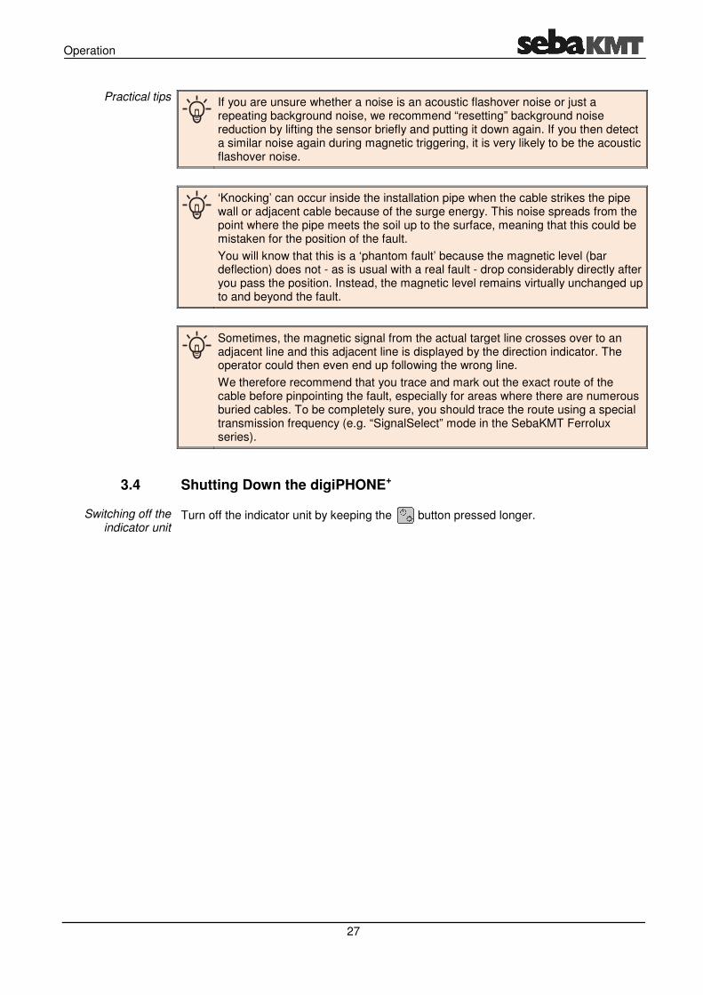
If you are unsure whether a noise is an acoustic flashover noise or just a repeating background noise, we recommend “resetting” background noise reduction by lifting the sensor briefly and putting it down again. If you then detect a similar noise again during magnetic triggering, it is very likely to be the acoustic flashover noise.
‘Knocking’ can occur inside the installation pipe when the cable strikes the pipe wall or adjacent cable because of the surge energy. This noise spreads from the point where the pipe meets the soil up to the surface, meaning that this could be mistaken for the position of the fault.
You will know that this is a ‘phantom fault’ because the magnetic level (bar deflection) does not - as is usual with a real fault - drop considerably directly after you pass the position. Instead, the magnetic level remains virtually unchanged up to and beyond the fault.
Sometimes, the magnetic signal from the actual target line crosses over to an adjacent line and this adjacent line is displayed by the direction indicator. The operator could then even end up following the wrong line.
We therefore recommend that you trace and mark out the exact route of the cable before pinpointing the fault, especially for areas where there are numerous buried cables. To be completely sure, you should trace the route using a special transmission frequency (e.g. “SignalSelect” mode in the SebaKMT Ferrolux series).
3.4 Shutting Down the digiPHONE+
Turn off the indicator unit by keeping the button pressed longer.
Practical tips
Switching off the indicator unit
Storage and Transport
28
4 Storage and Transport
If you do not expect to use the unit for over a month, you must remove the batteries and store them separately.
You should store the device in a dry and sheltered environment which provides adequate protection against mechanical damage and dirt. The storage temperatures shown in the technical data must be adhered to.
Only use the carry-bag supplied to transport the device. Please note that the ambient conditions along the entire transport route must comply with the technical data.
During transport, never hold the device by the connection cables only!
Long periods out of use and storage
Transport

Maintenance and Care
29
5 Maintenance and Care
To change the 6 x 1.5 V AA batteries, you must undo the two screws on the underside of the indicator unit by a quarter of a turn (e.g. using a coin) and then take off the battery compartment cover.
NiMH rechargeable batteries (AA type) can also be placed in the battery compartment. However, they must be charged using an external charger.
Do not clean the display with aggressive products such as solvents or spirits.
Instead, use lukewarm water and a soft, lint-free cloth for wet wiping, or a microfibre cloth for dry wiping.
Changing the batteries
Caring for the display