Biomimetic and Superwettable Nanofibrous Skins for Highly ...
Fall 2012 | Volume 17 Issue 4
SurFACTS in Biomaterials
Pg. 2: Shape Memory Polymers as “Self-Fitting” Scaffolds to Heal Bone DefectsBy Dawei Zhang and Melissa A. Grunlan, Texas A&M
Pg. 4: You Can Teach an Old Dog New Tricks: Spinning a New Polyester Nanofibrous Matrix for Medical DevicesBy Matthew D. Phaneut, Biosurfaces, Inc.
Pg. 7: Means-Plus-Function-Claims: What’s the Point? By Colin Fairman, JD, PhD, Surfaces Intellectual Property and Legal Editor
Pg. 10: Using a Combination of Microscopy and Spectroscopy to Confirm Covalent Bonding of DNA on Functionalized Semiconductor SurfacesBy Yue Liu and Andrew V. Teplyakov, U. of Delaware
Pg. 12: Surface Science Calendar of Events
Pg. 15: Surfaces in Biomaterials Supporting Members
Inside this Issue
Members are encouraged to submit articles for future editions of SurFACTS. Please e-mail your report (with all appropriate figures and graphics) to Staff Editor Cody Zwiefelhofer at [email protected] for
consideration in a future issue. Deadlines for upcoming issues are posted on surfaces.org.
From the Editorby Joe McGonigle, SurFacts Executive Editor
The 2012 BioInterface meeting in Dublin is coming up in less than a week and I’m looking forward to an outstanding meeting with a diverse program covering surface modification technologies for multiple applications. I feel that SurFacts is also doing a great job of providing articles from both academia and industry in multiple areas. This is reflected in this issue which features contributed articles on shape memory polymers for orthopedics, electrospun polymer fibers for medical device applications, characterization of nucleic acid binding to surfaces and recommendations on drafting patent claims.
I’d like to thank all of the folks who have contributed articles to SurFacts over the past year and would especially like to thank the subject area editors who have worked hard to help include more original content in SurFacts. With their support I feel that we have created an excellent resource to learn not just about new technical advances, but also about changes to the legal and regulatory landscape.
We plan to continue having SurFacts be a place to get novel information on all areas of biomaterials science as well as a place for Surfaces in Biomaterials Foundation members to get word out about their research and services to people in the biomaterials and medical device industry. I’m looking forward to seeing all of the members at the meeting and once again will make the rounds to make a pitch for contributing an article to SurFacts. Please let me know if you are interested or have any questions or comments about the newsletter and thanks again to everyone who has participated in the past year.

2
SurFACTS in Biomaterials is the official publication of the foundation and is dedicated to serving industrial engineers, research scientists, and academicians working in the field of biomateri-als, biomedical devices, or diagnostic research.
Foundation Officers
Dan Hook, PresidentBausch & Lomb1400 North Goodman StreetPO Box 30450Rochester, NY 14609-0450Telephone (585) 338-6580Peter Edelman, President-Elect Boston Scientific3 Scimed PlaceMaple Grove, MN 55311Telephone (763) 255-0282John O’Donoghue, Vice PresidentEnBIO Ltd.Rubicon CentreCIt CampusCork, IrelandTelephone +35315253305John Fisher, SecretaryW.L. Gore & Associates3250 West Kiltie LaneFlagstaff, AZ 86001Telephone (928) 864-3506Lawrence Salvati, TreasurerDePuy Orthopaedics700 Orthopaedic DriveWarsaw, IN 46581Telephone (574) 372-7220Marc Hendriks, Past PresidentDSM Biomedical P.O. Box 186160 MD GeleenThe NetherlandsTelephone +31464760278
Committee Chairs
MembershipRobert Kellar and Jeannette PolkinghorneBioInterface 2012 ProgramMarc HendriksBioInterface 2012 WorkshopJeannette PolkinghorneAwardsJeannette Polkinghorne
Foundation Office Staff
Andy Shelp, Executive Director1000 Westgate Drive, Suite 252St. Paul, MN 55114Telephone (847) 977-6153 Fax (651) 290-2266Email: [email protected]
SurFACTS in Biomaterials Editors
Executive EditorJoe McGonigleSurModics, [email protected]
Staff EditorCody ZwiefelhoferEwald [email protected]
Intellectual Property and Legal EditorColin Fairman, JD, Ph. D.Fulbright & [email protected]
Biomaterials EditorMelissa Reynolds, Ph. D.Colorado State [email protected]
Surface Characterization and Analysis EditorBill [email protected]
Regulatory EditorPhil TrioloPhil Triolo & Associates [email protected]
Advertising ManagerEwald [email protected]
© 2012 published by theSurfaces in Biomaterials Foundation.
All rights reserved.
The repair of a bone defect typically utilizes an autograft from a patient’s own fibula or iliac crest. However, this is often associated with an invasive harvesting procedure, donor site morbidity, as well as difficulties in shaping and positioning the graft to fit in the defect. As an alternative to autografts, tissue engineers are developing polymeric “scaffolds” that provide support to cells as they generate new tissue, including bone tissue. Recent efforts have focused on developing injectable scaffolds that may flow to fit inside a bone defect and then are solidified or cured. However, many of such in-situ forming scaffolds (e.g. bone cements and hydrogels) suffer from toxicity issues, an exothermic cure that can cause damage to adjacent tissue, a lack of mechanical integrity and also poor control over porosity necessary for tissue in-growth. Thus, a scaffold with well-defined pore size and pore interconnectivity and that would conformally fit into a bone defect would be ideal.
Toward this goal, researchers at Texas A&M University (College Station, Texas) have developed “self-fitting” scaffold based on a shape memory polymer (SMP) technology. SMPs are one class of responsive materials whose shape can be modulated by temperature change. The “netpoints” are chemical or physical crosslinks that define the permanent shape. The “switching segments” maintain the temporary shape and recover the permanent shape upon heating through the shape transition temperature (Ttrans). The Ttrans may either be a glass transition temperature (Tg) or a melt transition temperature (Tm). Thus, a temporary shape formed at T > Ttrans can be fixed by cooling to T < Ttrans and permanent shape recovered by re-heating to T > Ttrans (Figure 1).1 In the biomedical field, SMPs are of particular
interest and have been proposed for various devices such as self-expanding cardiac stents and porous embolic sponges to treat aneurysms.
These self-fitting scaffolds are based
on a novel class of hybrid SMPs that are comprised of organic “switching” segments [poly(ε-caprolactone), PCL] and inorganic “softening” segments [polydimethylsiloxane, PDMS] (Figure 2a).2,3 The photosensitive macromers (dissolved in an organic solvent) are cured with UV-light to produce covalently crosslinked networks. The semi-crystalline PCL segments (Ttrans = Tm = ~52 ºC) are the source of the shape changing behavior. Varying the PDMS and PCL segment lengths permits tuning the mechanical properties and degradation rate of the SMP. Porous SMP scaffolds are prepared by photocrosslinking the macromer solution in the presence of a continuous porogen template which was previously formed by fusing NaCl particles with a small amount of water. After solvent removal and salt leaching, a SMP scaffold with a highly interconnected porous structure of controlled pore size is achieved (Figure 2b). The properties of the SMP scaffolds are readily tunable by tailoring fabrication parameters including the extent of salt
Shape Memory Polymers as “Self-Fitting” Scaffolds to Heal Bone Defects
By Dawei Zhang and Melissa A. Grunlan, Grunlan Research Group, Dept. of Biomedical Engineering, Texas A&M University
Figure 1. Molecular mechanism of macroscopic shape memory behavior. From Behl and Lendlein, 20071.
Shape Memory Polymers Continued on Page 3
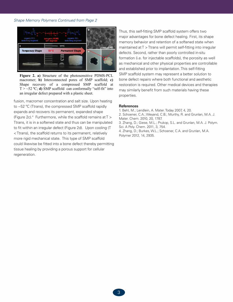
fusion, macromer concentration and salt size. Upon heating to ~52 ºC (Ttrans), the compressed SMP scaffold rapidly expands and recovers its permanent, expanded shape (Figure 2c).4 Furthermore, while the scaffold remains at T > Ttrans, it is in a softened state and thus can be manipulated to fit within an irregular defect (Figure 2d). Upon cooling (T < Ttrans), the scaffold returns to its permanent, relatively more rigid mechanical state. This type of SMP scaffold could likewise be fitted into a bone defect thereby permitting tissue healing by providing a porous support for cellular regeneration.
Thus, this self-fitting SMP scaffold system offers two major advantages for bone defect healing. First, its shape memory behavior and retention of a softened state when maintained at T > Ttrans will permit self-fitting into irregular defects. Second, rather than poorly controlled in-situ formation (i.e. for injectable scaffolds), the porosity as well as mechanical and other physical properties are controllable and established prior to implantation. This self-fitting SMP scaffold system may represent a better solution to bone defect repairs where both functional and aesthetic restoration is required. Other medical devices and therapies may similarly benefit from such materials having these properties.
References1. Behl, M.; Lendlein, A. Mater. Today 2007, 4, 20.2. Schoener, C.A.; Weyand, C.B.; Murthy, R. and Grunlan, M.A. J. Mater. Chem. 2010, 20, 1787.3. Zhang, D.; Giese, M.L.; Prukop, S.L. and Grunlan, M.A. J. Polym. Sci. A Poly. Chem. 2011, 3, 754.4. Zhang, D.; Burkes, W.L.; Schoener, C.A. and Grunlan, M.A. Polymer 2012, 14, 2935.
Shape Memory Polymers Continued from Page 2
3
Temporary Shape Permanent Shape52°C
organic PCLswitching segment
inorganic PDMSsoft segment
organic PCLswitching segment
200 µm
a b
c
d
Figure 2. a) Structure of the photosensitive PDMS-PCL macromer; b) Interconnected pores of SMP scaffold; c) Shape recovery of a compressed SMP scaffold at T > ~52 ºC; d) SMP scaffold can conformally “self-fit” into an irregular defect prepared with a plastic sheet.

4
You Can Teach an Old Dog New Tricks: Spinning a New Polyester Nanofibrous Matrix for Medical Devices
By Matthew D. Phaneuf, BioSurfaces, Inc.
Figure 1: Photograph of an explanted PET artificial blood vessel. Note formation of blood clot on the surface of the vessel with lack of cellular healing.
Polyester (polyethylene terephthalate or PET) has been utilized in medical devices since the early 1950s, especially for synthesizing artificial blood vessels (grafts). This polymer has excellent mechanical and physical properties as well as long-term biodurability once implanted. PET fibers also have excellent handling characteristics, can be formed into various constructs and can undergo some degree of surface modification if necessary. These basic properties make PET an attractive polymer to employ strength and durability as the main structural component of many medical devices such as artificial blood vessels, conduits for heart assist devices, sewing rings for heart valve repair/replacement, sutures and repair mesh. Devices comprised of PET have been shown to improve patient outcome when faced with a debilitating illness (e.g. using a PET artificial artery to bypass a diseased segment of an artery). However, there are still major issues when using PET (as well as many other inert polymers) such as lack of appropriate cellular healing into and onto the device, blood clot formation on the biomaterial surface and bacterial contamination with subsequent infection (Figure 1).
While there have been many incremental advances in PET technology over the past several decades, many of the same fabrication technologies continue to be applied in order to manufacture these devices. BioSurfaces, Inc., a privately held company, specializes in developing new and innovative medical devices using our proprietary cutting-edge electrospinning technology. The company’s proprietary technology is used to create new devices that have a spider web-like composition (nanotechnology) in conjunction with custom-designed biologic properties that target specific issues within the body, thereby providing a multi-faceted approach to a
problem. Electrospinning provides a new technique for controlled fiber modification as well as new nanocomposite substrates. A major benefit of our electrospinning technology is that these nanofibers are formed at low temperatures, unlike standard polymers which are extruded at high temperatures via melt spinning or by wet spinning. Another benefit of our technology is that it allows direct incorporation of selected pharmaceutical agents into the electrospun fibers during the synthesis process. Direct incorporation of biologically-active agents into the nanofibrous polyester fibers holds several key advantages over other application methodologies in that: 1) the active agent incorporates into the nanofibrous material without molecular modification, 2) the amount of active agent can be adjusted within the bulk polymer depending on the specific application, 3) no cross linking agents are needed, avoiding concerns over drug carrier toxicity and biocompatibility, 4) low temperatures are used during the fiber formation, maintaining the biologic activity of the active agent and 5) active agent elution is controlled and sustained.
BioSurfaces, Inc. is developing various medical devices using our proprietary technology, with several of these technologies already advancing through animal trials from several small business grants and contracts funded by the National Institutes of Health and the National Science Foundation. Our first objective focused on developing a small-diameter artificial blood vessel (BioSpun-VG), which would have a significant impact on small vessel repair and replacement. These grafts would be predominantly utilized in peripheral arterial bypass procedures, which are continuing to rise due an aging population as well as an increase in diabetes. A semi-automated manufacturing process to reproducibly synthesize the BioSpun-VG (4mm internal diameter) was developed, with physical and biologic properties characterized. Various lengths and internal diameters can be also made with this process. Implantation of the BioSpun-VG grafts demonstrated that these thin walled grafts had excellent handling properties, were easily anastomosed to the blood vessel and had no blood permeation through either the graft wall or the suture sites. Additionally, these grafts had no surface thrombus formation upon explantation as compared to the woven PET materials which had thrombus deposition on the luminal surface.
You Can Teach an Old Dog New Tricks Continued on Page 5

5
Figure 3: Photograph of BioSpun-VAD conduit, which has excellent kink-resistance and the ability to prevent infection and clot formation.
You Can Teach an Old Dog New Tricks Continued from Page 4
You Can Teach an Old Dog New Tricks Continued on Page 6
Figure 4: Photograph of ePFTE, BioAccess control and BioAccess drug-loaded grafts. Note that BioAccess grafts self-sealed after regardless of the needle gauge utilized.
Interestingly, BioSpun-VG grafts showed cellular healing which occurred throughout the mid-portion of these grafts with extensive capillary formation throughout the graft wall, a finding that has never been observed with an artificial blood vessel (Figure 2). BioSurfaces, Inc. is developing, using a contract from the National Heart, Lung and Blood Institute, an outflow conduit (BioSpun-VAD) to be used for Ventricular Assist Devices (VADs) for the heart. Heart failure affects more than 4.7 million Americans, with 550,000 new cases diagnosed each year. Of these cases,
approximately 50,000 to 100,000 patients are in late-stage heart failure with only 8% of these patients surviving two years without undergoing a heart transplant or implantation of a VAD.
Although VADs have improved the quality of life for patients in late-stage heart failure, only 2,000 patients receive VADs each year due to the high morbidity and mortality associated with these devices. VADs, specifically the outflow conduit of these devices, are prone to two major complications: thrombosis/thromboembolic phenomenon and infection. Our nanofibrous conduits (Figure 3) is designed to prevent bacterial infection as well as clot formation within the conduit. The BioSpun-VAD conduit
had both biologic properties remaining, even after 60 days (length of study) of implantation and when exposed to a direct bacterial challenge (Table 1). Similar to the BioSpun-VG graft, the BioSpun-VAD conduit showed cellular healing which occurred throughout the mid-portion of these grafts with extensive capillary formation throughout the graft wall.
There are several up-and-coming technologies that BioSurfaces, Inc. is currently developing. In continuation with the company’s platform technology of developing the next generation of artificial blood vessels, a new hemodialysis access graft (BioAccess) is currently entering animal trials. End Stage Renal Disease (ESRD) is a disease affecting more than a half million Americans. The overall annual cost of ESRD treatment in the US alone is $23 billion, which is projected to increase 3.6% every year. About 2 million patients worldwide (355,000 in US) already have received hemodialysis treatment by 2010. Of these cases, 355,000 patients selected hemodialysis over treatments such as renal transplant or peritoneal dialysis. BioAccess is designed to permit quicker access due to self-sealing capabilities (Figure 4) as well as prevent clotting, infection and unregulated cellular growth.
The company is also developing a drug-eluting stent sheath (DE Stent Sheath). More than 1.1 million stents are implanted annually in the United States. Occlusion rates for diseased blood vessels after placement of a bare metallic stent (restenosis) have been reported as high as 27%, a significant problem based on the total number of stents annually implanted. Unregulated cellular growth within the body can have catastrophic consequences as evidenced in cancer and cardiovascular disease where abnormal proliferation of neointimal smooth muscle cells is central to lesions of atherosclerosis and restenosis. This stent sheath technology permits incorporation of a selected drug(s) within
Figure 2: Histological evaluation of the mid-portion of a woven PET (A) and BioSpun-VG (B) grafts implanted for 30 days. BioSpun-VG had cellular healing throughout wall and graft surface with no clot formation as complain contrast to woven PET, which had significant clot formation and lacked cellular ingrowth.
A
B

6
You Can Teach an Old Dog New Tricks Continued from Page 5
a desired location of a stent device while still allowing normal stent deployment (Figure 5). Lastly, a nanofibrous bioactive PET suture material (BioSuture DE – Figure 6) is being developed. For example, approximately 1 million people sustain SSIs in the United States each year, and two out of three of these infections
are confined to thesuperficial and deep incision sites where sutures are implanted. A nanofibrous bioactive suture that will be able to provide a specific biologic effect directly at the implant site while being fully-integrated into the surrounding tissue is desired. BioSurfaces, Inc. is currently looking to develop new relationships, either through licensing of our technology or through strategic partnerships, in order to advance these technologies toward clinical use. For questions about the information presented or inquiries about the technology,
please contact the author at: [email protected].
Figure 5: Cross-section of DE Stent Sheath, observed under visible and fluorescent microscopy. Note that a selected drug can be localized to the inner (as shown in red) or outer area of device.
Figure 6: Photograph of ePFTE (left) and BioSuture DE (right). Various thicknesses and lengths can be manufactured.

35 U.S.C. 112 Specification. An element in a claim for a combination may be expressed as a means or step for performing a specified function without the recital of structure, material, or acts in support thereof, and such claim shall be construed to cover the corresponding structure, material, or acts described in the specification and equivalents thereof.
Seminally, the Court of Appeals for the Federal Circuit (CAFC) in In re Donaldson Co., (16 F.3d 1189 )(1994) held that the scope of a “means-plus-function” (MPF) claim should be interpreted differently than non-MPF claims. Prior to Donaldson, when the patent office made a determination of patentability under 35 U.S.C. § 102 (Novelty) or 103 (Obviousness) the limitation in a claim was given its “broadest reasonable interpretation.” Thus, any limitation in a claim is interpreted as reading on any prior art “means” which performed the function attributed to it in the claim without regard for whether the prior art means was equivalent to the corresponding structure. In Donaldson, the CAFC held:
Per our holding, the “broadest reasonable interpretation” that an examiner may give means-plus-function language is that statutorily mandated in paragraph six. Accordingly, the PTO may not disregard the structure disclosed in the specification corresponding to such language when rendering a patentability determination.
In interpreting the practical implications of Donaldson on claim construction, the Patent Office provides the following guidance to its examiners:
The USPTO must apply 35 U.S.C. 112, sixth paragraph in appropriate cases, and give claims their broadest reasonable interpretation, in light of and consistent with the written description of the invention in the application. See, Donaldson, 16 F.3d at 1194, 29 USPQ2d at 1850 (stating that 35 U.S.C. 112, sixth paragraph “merely sets a limit on how broadly the PTO may construe means-plus-function language under the rubric of reasonable interpretation”). MPEP 2181.
The question then arises, is there a value in means-plus-function claiming? How do the requirements of 35 U.S.C.
112 intersect with the requirements 35 U.S.C. 112, written description and enablement (See my column in the Spring issue of SurFacts). Do MPF claims have a smaller world of prior art – and therefore a greater chance of patentability – simply because the elements of the claim are limited by their definition in the specification?
U.S. patent 5,376,957 used the following terminology to claim an apparatus for printing large signs.1. An apparatus for reproducing an image on a first side of a substrate and a mirror image on a second side of said substrate, comprising: • a frame; • means for generating control signals representative
of said image; • ink delivery means positioned on opposite sides
of said substrate, said ink delivery means fluidly communicating with an ink source;
• means mounted on said frame for supporting said ink delivery means;
• means mounted on said frame for driving said ink delivery means relative to said substrate; and
• means, responsive to said control signals, for controlling said ink delivery means to produce said image on said first side of said substrate and said mirror image on said second side of said substrate.
Because the claims are written as means-plus-function, without recital of structure, the physical composition of each of the elements of the claim must be construed in light of the specification. The ‘957 patent describes an improved sprayhead for an ink jet printer. The specification teaches that the improvement of the sprayhead is provided by having one pressurized air source to control ink delivery and a second, low-volume, high pressure air source to continuously clean the ink nozzle during printing. When the patent was asserted against a purported infringer, the judge determined that the alleged infringing device simply could not infringe because the term “ink delivery means positioned on opposite sides of said substrate, . . .” must be read as an MPF claim (one topic of the litigation was, is an “ink delivery means” the same as a “means for ink delivery”). See, Signtech USA, Ltd. v. Vutek, Inc., 174 F.3d 1352, 1356 (CAFC, 1999). Because the Judge determined that the phrase was an MPF phrase and the purported infringer had only one air source, when interpreted in light
Means-Plus-Function Claims: What’s the Point?By Colin Fairman, SurFacts Intellectual Property and Legal Editor
Means-Plus-Function Claims Continued on Page 87

8
of the specification, the defendant could not infringe. The specification provided no other alternative than to a two-air source nozzle. How could the claim have been written in order to be given a broader reading no limited by the specification?
1. An apparatus for printing an image comprising:• a frame;• a computer generating control signals
representative of the image;• a sprayhead delivering ink to each side of the
substrate;• a support on the frame holding the sprayhead;
and• a transom holding the sprayhead and accepting
the control signals of the computer thereby generating an image.
Because the claim is not written as a MPF claim, the claims can be interpreted by the court to have their broadest reasonable interpretation, when viewed in light of the specification. Thus, some language in the specification that the two-head nozzle was “an exemplary embodiment” may have provided room for the judge to give the claims their broadest, reasonable, interpretation, e.g., a spray head with one or more nozzles. Of course, the two-nozzle configuration of the print head may have novelty and nonobviousness.
As with many aspects of patent law, the use of means-plus-function (MPF) claiming has gone in and out of style. One reason for this may be that the examination process for U.S. patents is becoming stricter and more rigorous with respect to enablement and written description requirement as we discussed in the last issue of SurFacts. As the value of patents is becoming more widely recognized and they are asserted in litigation, the courts are requiring a more strenuous analysis of patentability by the Patent Office. The Patent Office, in return, is increasing its scrutiny of the support found in the description for the claims.
However, because paragraph 6 allows the claims to be interpreted consistent with the specification, the universe of means providing the function recited in the claims must be cogently discussed. This year the CAFC found a patent invalid because the claims, written as MPF, did not meet the requirements of 35 U.S.C. 112.
Consider:1. Multichannel metering system for metering preselected fluid flows, comprising: • a plurality of individual fluid flow sources; • a plurality of discharge lines, each line of said
discharge lines being connected to a corresponding one of said fluid flow sources;
• adjusting means associated with said fluid flow sources for acting on said fluid flow sources to influence fluid flow of said fluid flow sources;
• programmable control means coupled with said adjusting means for controlling said adjusting means, said programmable control means having data fields describing metering properties of individual fluid flows;
• an operating surface connected to said control means;
• data input means for input of data into said control means, said data input means being at least partially connected to said operating surface;
• data output means for output of data from said control means, said data output means being connected to said operating surface; . . .
In litigation, the accused infringer asserted that the patent was invalid as indefinite for failing to particularly identify the structure of the “programmable control means” and “control means,” The specification describes the use of a data input and data output, and that “the data input circuit may be designed in the form of discrete keys, with which command information can be entered into the control device.” However, the specification never identified the “programmable control means” as the control device and, more importantly, never identified that the control device could be a computer. Thus, the Court held that the generic identification of a “control device” without further elaboration on what exactly might constitute a control device did not meet the requirements of the written description regardless of whether the claims were written as MPF or not. See, Ergo Licensing, LLC v. Carefusion 303, Inc., 673 F. 3d 1361 (CAFC, 2012).
Undoubtedly, the claims in Ergo could have been saved if the drafting attorney had clearly defined his terms. Perhaps he fell into a trap of too clever patent drafting where by not defining the terms, he thought he had made the claims broader. Perhaps he thought that between the drawings (showing what looks like a passable work station) and the
Means-Plus-Function Claims Continued from Page 7
Means-Plus-Function Claims Continued on Page 9

9
discussion of the “control device’ any ordinary person would assume that the programmable control means was a computer. In any case, it should be noted that even were the claims not written as MPF claims, the meaning of the claim terms would still have to be defined. However, were the terms written in their vernacular, the court could have, if it wanted, recognized their ordinary and customary meaning and Ergo may have prevailed in proving infringement.
Why would one want to draft means plus function claims when the outcome of their interpretation may be perpetually clouded? Consider the following example:
A cardiac prosthesis for reconfiguring cardiac geometry comprising:
• i) a means for reducing the size of a valve annulus;• ii) a means for realigning the papillary muscles; and • iii) means for connecting parts (i) and (ii).
vs.
A cardiac prosthesis for reconfiguring cardiac geometry comprising:
• i) an annuloplasty device;• ii) a papilloplasty device; and• iii) neo-chords connecting parts (i) and (ii).
In the above case, the specification describes the use of “bands” or rings such as an annuloplasty ring that can be used to provide both the annuloplasty device and the papilloplasty device. When written in a non-MPF format, the examiner was able to find all the elements in prior art directed at the previously described annuloplasty device. Further, the neo-chords could be found in traditional sutures used to deploy the annuloplasty device. Therefore, the examiner was able to find the elements without regard to their unique arrangement and interconnectedness.
Now consider, the interpretation of the claims written as MPF claims. According to 112 the examiner would have to interpret the claims as disclosed in the specification. Therefore, not only would the identification of multiple annuloplasty rings not have read on the claimed papilloplasty device, the neo-chords would not have read on common sutures used to, for example, attach the annuloplasty device to the annulus. The examiner would have been required to search the art for elements that had the specific function ascribed to them in the specification. Lacking the “means”
having the specific function ascribed to them in the specification, prior art reading on annuloplasty rings could not be asserted against the papilloplasty device.What’s the bottom line? Generally, it would seem unnecessary to use MPF claims in protecting your invention. In a utility application three independent claims are included in your filing fee. Most practitioners have little problem in using up the three independent and 17 dependent claims included with the examination fee (extra claims can be purchased with a surcharge). However, it may be effective to use MPF claims in a crowded field, especially where the invention comprises new uses or configurations of previously known components. Of course, claims are almost always amended during prosecution. An ongoing evaluation of strategies to gain patent allowance is always a good rule and while MPF claims in a valuable patent will surely be scrutinized by your competitors, MPF claims that are fully enabled and definite can still provide valuable coverage when non-MPF claims may not be available.
Means-Plus-Function Claims Continued from Page 8

Covalent attachment of biomolecular structures to semiconductor surfaces is of great importance in a number of fields, including biofunctionalization, DNA-computing, and biosensing. In biosensing, and in particular, for sensors that involve DNA-based field effect transistors (DNA-FETs), covalent attachment of DNA molecules to semiconductor substrates allows for an all-electric detection with easily quantifiable electric response. In this type of application, a well-defined oxide-free interface with covalently bound DNA molecules is often required.1 Among several available approaches for DNA immobilization on silicon substrates, biocompatible amine-terminated self-assembled monolayers (SAMs) can be used to be further modified by sulfo-SMCC crosslinker that can in turn selectively react with thiol-DNA to produce robust covalent linkages.2-3 In our recent work we used a similar approach to covalently bind shape-restricted DNA molecules to silicon single crystalline surfaces. The obtained system can be visualized by atomic force microscopy (AFM).1,4 The procedure utilized commercially available Si(111) wafers etched in buffered-HF and NH4F according to previously established protocols 5 to obtain a uniform H-terminated silicon surface. This surface was further reacted with a t-boc-protected 1-amino-10-undecene to form a well-ordered SAM.6-7 Following this step, deprotection chemistry resulted in a SAM terminated with primary amino-groups (-NH2) that were further reacted with sulfo-SMCC crosslinker. Shape restricted DNA molecules with thiol linkers were designed and prepared according to the origami method proposed by Rothemund. 8 We’ve designed Y-shaped DNA (from three complementary strands) and rectangle-shaped DNA molecules (from single-stranded circular M13mp18 DNA and 80 staple-strands) and reacted them with the SSMCC-terminated SAM on silicon to produce strong covalent bonds.1,4 As in any novel method, we had to prove that the proposed procedure indeed resulted in covalent binding and that the DNA molecules were stable on semiconductor substrates. Because of the intrinsic complexity of the interface produced, no single analytical technique could be used to interrogate the nature of chemical bonding of DNA on silicon. We had to use a combination of AFM, X-ray photoelectron spectroscopy (XPS), and time-of-flight secondary ion mass spectrometry (ToF-SIMS) to confirm this reaction.
Figure 1: a) rectangular DNA with two thiol linkers on mica; b) rectangular DNA with two thiol linkers on functionalized silicon.
Rectangle-shaped DNA (r-DNA) molecules can be easily identified by atomic force microscopy. Figure 1 compares r-DNA molecules adsorbed on mica (a) and on functionalized silicon substrate (b). The size of this DNA origami matches well with the expected size of single molecule features in both cases (~25nm×100nm). The apparent height for thiol r-DNA on silicon is 2 nm, noticeably higher than
that on mica, ~1 nm. This difference can be explained by different types of binding of r-DNA on two surfaces. On mica, the entire r-DNA molecule is bound by strong but non-specific interactions, while on modified silicon, it is anchored through two thiol linkers in specific parts of the molecule, with the rest of the DNA structure essentially “floating” above the surface bound only via weak van der Waals type bonding. Having the flexibility of placing the thiol linkers in many anchor points of a single DNA molecule, we have later designed an r-DNA with 4 thiol linkers at each corner of the rectangular structure, which decreased the apparent height to ~1.5 nm.4 It can be noted that smaller Y-shaped DNA structure can be deposited on the same surface at much higher concentration. However, it is difficult to use AFM for quantification of surface concentration in that case. Most importantly, despite the fact that AFM is an excellent method to visualize the attachment result, it is impossible to probe the nature of chemical bond by this technique. XPS is commonly used as a perfect tool to probe the nature of chemical bonds in surface species. XPS results of interrogation of silicon surface modification steps for DNA attachment shown in Figure 2 are consistent with all the modification steps with all the intensities increasing in both carbon and nitrogen regions. Unfortunately, because
Using a Combination of Microscopy and Spectroscopy to Confirm Covalent Bonding of DNA on Functionalized Semiconductor Surfaces
By Yue Liu and Andrew V. Teplyakov, Dept. of Chemistry and Biochemistry, U. of Delaware
10
Using a Combination of Microscopy and Spectroscopy Continues on Page 11

of the sheer size of the molecular structures interrogated, it is impossible to discern any specific molecular features. The one element that could be most informative in structure identification, sulfur, is notoriously difficult to follow with this technique in biological samples. It has very low atomic concentration in our system, relatively low sensitivity, hindered by the overlap between silicon 2s and sulfur 2p signal,9 and in addition it is screened by the large scaffold structures protecting it from spectroscopic interrogations. Thus, despite being consistent with every modification step, XPS does not prove covalent binding of the shape-restricted DNA molecules on a functionalized silicon surface.
Figure 2. XPS spectra of carbon and nitrogen signal after each step of surface modifications.
Thus, a very sensitive technique, ToF-SIMS was used to monitor the sulfur signal of the thiol bond between the DNA and the crosslinker sulfo-SMCC before and after DNase І enzyme digestion was used to remove the rest of the DNA structure, as summarized in Figure 3. This figure clearly shows that the sulfur signal (m/z- = 32) remained observed after the enzyme digestion. At the same time, the rest of the peaks belonging to the DNA fragments: CNO- ion (m/z = 42), PO2- (m/z = 63), PO3- (m/z = 79), SO3- (m/z = 80) and H2PO4- (m/z = 97) disappeared. In other words, the use of ToF-SIMS together with biochemical methods of DNA digestion proves that the binding of DNA on a functionalized silicon substrate is covalent. In this work, the shape restricted thiol DNA was covalently attached to silicon substrate based on amine-terminated SAM through sulfo-SMCC crosslinker. A combination of spectroscopy, biochemistry and microcopy had to be used
to prove that this procedure leads to the covalent binding of DNA on a functionalized silicon substrate.
Figure 3. Negative ToF-SIMS spectra of a) amino-terminated SAM on Si(111) substrate; b) Y-shaped DNA attached to Si(111); c) DNA attached to Si(111) substrate after DNase digestion.
References:1. Zhang, X.; Kumar, S.; Chen, J.; Teplyakov, A. V. Surface Science 2009, 603, 2445.2. Strother, T.; Cai, W.; Zhao, X. S.; Hamers, R. J.; Smith, L. M. J. Am. Chem. Soc. 2000, 122, 1205.3. Strother, T.; Hamers, R. J.; Smith, L. M. Nucleic Acids Res. 2000, 28, 3535.4. Zhang, X. C.; Antonopoulos, I. H.; Kumar, S.; Chen, J.; Teplyakov, A. V. Appl. Surf. Sci. 2009, 256, 815.5. Higashi, G. S.; Becker, R. S.; Chabal, Y. J.; Becker, A. J. Applied Physics Letters 1991, 58, 1656.6. Zhang, X.; Teplyakov, A. V. Langmuir 2008, 24, 810.7. Tian, F. Y.; Ni, C. Y.; Teplyakov, A. V. Appl. Surf. Sci. 2010, 257, 1314.8. Rothemund, P. W. K. Nature 2006, 440, 297.9. Coulter, S. K.; Schwartz, M. P.; Hamers, R. J. J. Phys. Chem. B 2001, 105, 3079.
Using a Combination of Microscopy and Spectroscopy Continued from Page 10
11

1212
Surface Science Calendar of Events
BioInterface 2012October 23-25, 2012Dublin, Irelandhttp://www.BioInterface2012Ireland.com
AIChE 2012 Annual MeetingOctober 28-November 2, 2012Pittsburgh, PAhttp://www.aiche.org/Conferences/AnnualMeeting/index.aspx
12
INTERFACE2012BIO

Join the Foundation that connects the academic, industrial, and regulatory committees within the surface science/biomedical communities!
Benefits of Membership:
•DiscountedregistrationatBioInterface,theannual symposium of the Surfaces in Bioma-terials Foundation.
•YourlogoandalinktoyourWebsiteinthemember directory on the official Web site of the Foundation, www.surfaces.org.
•ComplimentaryfullpageadinSurFACTS,theFoundation’s newsletter and discounts on all advertising.
Visit the Foundation at www.surfaces.org for a membership application or call 651-290-6267.
Wanted: MembersTo be leaders in the surface science community
•Joinaforumthatfostersdiscussionandsharingof surface and interfacial information•Haveyourvoiceheardandyourinterests represented within the surface science and biomedical community•Help shape workshops and symposia that further the world-wide education of surface sci-
ence•Promoteunderstandingofinterfacial issues common to researchers, bio-medical engineers and material
scientists.

Coatings
2GoCoatings2go, LLC provides hydrophilic and other coatings that are quickly delivered to you hassle-free,
and in a cost-effective manner. Our coatings are perfect for on-site manufacturing, eco-friendly, and can be
controlled by your employees, in your own facility, and are FDA Master Filed. They are easy to customize
and offer you performance and versatility, with no license fees or royalty costs. You can purchase domestically
or internationally through our quick and secure online ordering.
Please visit www.Coating2Go.com to view a full selection of coatings.
+ 1 9 7 8 . 3 6 9 . 7 4 11 www.Coatings2Go.com
ORDER NOW!
© 2012 Surface Solutions Laboratories, Inc. All Rights Reserved. SURFACE SOLUTIONS LABORATORIES is a trademark of Surface Solutions Laboratories, Inc. registered in the United States Patent and Trademark Office. COATINGS2GO is a trademark of Coatings2Go, LLC registered in the United States Patent and Trademark Office.
SURFACE SOLUTIONS LABORATORIES®
Coatings2Go® water-based coatings directly to you.
Surface Solutions LaboratoriesTM
TM
Surface Solutions Laboratories, Inc. was started in 1995. Our experienced staff holds nine U.S. patents—and brings a breadth of medical device industry expertise, with 35-plus years of design and formulation of coatings and adhesives across many market platforms. SURFACE SOLUTIONS LABORATORIES® coatings are based upon the proprietary technology of Surface Solutions Laboratories, Inc. Coatings2Go, LLC is a licensee of Surface Solutions Laboratories, Inc. technology.

15
Thank You to Our Members!
A S U B S I D I A R Y O F W . L . G O R E & A S S O C I A T E S