Surface Treatments and Coatings - Vander Voort
8
PREPARATION AND CHARACTERIZATION OF SURFACE TREATED AND COATED STEELS George F. VANDER VOORT Buehler Ltd., 41 Waukegan Road, Lake Bluff, Illinois 60044 USA [email protected] ABSTRACT A wide variety of surface treatments and coatings are applied to metals to enhance their performance, for example, to improve fatigue resistance, increase wear resistance, corrosion or oxidation resistance. Some of these treatments involve diffusion of one or more elements into the metal or alloy followed by post heat treatments. These processes included the familiar processes of carburizing, nitriding, and carbonitriding but also included less familiar processes such as ion nitriding and boriding. There are also a wide variety of coatings that are deposited by hot-dipping, electroless or electrolytic means, by physical or chemical vapor deposition, or by thermal or plasma spray. The technological significance of these processes is enormous. Keywords: surface treatments, metallography, specimen preparation, case depth, microstructure 1: SPECIMEN PREPARATION Metallographic examination of these surface layers is important in the development and implementation of these technologies. Metallographic preparation of such specimens is not a trivial matter as the affected surfaces can be badly damaged or altered by the use of poor practices. Beyond this, the preparation method must reveal the true structure so that it can be properly interpreted, measured, evaluated and documented. Every step of the procedure must be properly executed if the examination is to yield maximum value. Sectioning is almost always required as the first step in the preparation sequence. This is a crucial step as substantial damage can be produced if this step is performed poorly. The adhesion of some coatings may not be strong and cutting may separate the coating from the substrate, especially if the cut begins in the substrate and ends in the coating. This puts the coating in tension, which is almost always detrimental. Always perform cutting so that the surface layers are in compression. Of course, for some components, such as a round shaft, there is no way to keep the entire coating in compression, unless you can rotate the shaft as it is being cut. This can be done with some precision saws, depending upon the diameter of the piece being cut. For certain delicate layers (particular in failure analysis studies) it may be necessary to encapsulate the part in a castable epoxy resin before sectioning; otherwise the surface layers may flake off and be lost.
Transcript of Surface Treatments and Coatings - Vander Voort
PREPARATION AND CHARACTERIZATION OF SURFACE TREATED AND COATED STEELS
George F. VANDER VOORT
Buehler Ltd., 41 Waukegan Road, Lake Bluff, Illinois 60044 USA [email protected]
ABSTRACT
A wide variety of surface treatments and coatings are applied to metals to enhance their performance, for example, to improve fatigue resistance, increase wear resistance, corrosion or oxidation resistance. Some of these treatments involve diffusion of one or more elements into the metal or alloy followed by post heat treatments. These processes included the familiar processes of carburizing, nitriding, and carbonitriding but also included less familiar processes such as ion nitriding and boriding. There are also a wide variety of coatings that are deposited by hot-dipping, electroless or electrolytic means, by physical or chemical vapor deposition, or by thermal or plasma spray. The technological significance of these processes is enormous.
Keywords: surface treatments, metallography, specimen preparation, case depth, microstructure
1: SPECIMEN PREPARATION
Metallographic examination of these surface layers is important in the development and implementation of these technologies. Metallographic preparation of such specimens is not a trivial matter as the affected surfaces can be badly damaged or altered by the use of poor practices. Beyond this, the preparation method must reveal the true structure so that it can be properly interpreted, measured, evaluated and documented. Every step of the procedure must be properly executed if the examination is to yield maximum value.
Sectioning is almost always required as the first step in the preparation sequence. This is a crucial step as substantial damage can be produced if this step is performed poorly. The adhesion of some coatings may not be strong and cutting may separate the coating from the substrate, especially if the cut begins in the substrate and ends in the coating. This puts the coating in tension, which is almost always detrimental. Always perform cutting so that the surface layers are in compression. Of course, for some components, such as a round shaft, there is no way to keep the entire coating in compression, unless you can rotate the shaft as it is being cut. This can be done with some precision saws, depending upon the diameter of the piece being cut. For certain delicate layers (particular in failure analysis studies) it may be necessary to encapsulate the part in a castable epoxy resin before sectioning; otherwise the surface layers may flake off and be lost.

For maximum edge retention, it is necessary to mount specimens before commencing the grinding and polishing steps. A free edge will always be rounded to some extent, regardless of the procedures used. But, mounting resins vary in their ability to provide edge protection. Polymeric resins will tend to shrink away from the encapsulated piece forming a small gap between specimen edge and mount. This gap must be avoided or minimized. A shrinkage gap creates a free edge where rounding will occur and also leads to seepage problems which may cause contamination of the polishing steps or bleed out of solvents or the etchant which will obscure the edge structure. Protective platings, such as electroless nickel, are helpful when done properly but are not a guarantee for edge retention. The plating must be compatible with its substrate, must adhere well, and must not interfere with the etching reaction or exhibit the same contrast as the coating.
Grinding may be done with a variety of products, such as traditional SiC paper, alumina paper, metal- or resin-bonded diamond disks, or rigid grinding discs. In general, one grinding step is adequate. The cut surface should be made with an abrasive cut-off saw or a precision saw. Both produce high quality cut surfaces with minimal damage depths. Consequently, coarse grinding abrasives are not needed, and should be avoided, as they produce excessive damage. Generally, one can commence grinding with a SiC paper with an abrasive size of 240-grit (P220 or P280) after abrasive cutting or 320-grit (P400) after use of a precision saw. When using an automated grinder/polisher and a specimen holder for 6 or more specimens, it is best to commence grinding with 120-grit SiC if the specimens are =60 HRC, with 180-grit SiC if they are 35-60HRC, or with 240-grit SiC if they are =35 HRC. In the first step, besides removing cutting damage, all of the specimens in the holder must be ground to a common plane.
Polishing should be conducted using napless cloths. For the first rough polishing step, a silk cloth, such as the UltraPol™ cloth, with 9-µm diamond abrasive produces excellent results with a good removal rate and an excellent surface finish. The second polishing step uses 3-µm diamond and a napless cloth is chosen, such as the synthetic chemotextile pads, like Texmet®, or a fine woven cloth, such as a TriDent™ cloth. Depending upon the material being prepared, a 1-µm diamond step may be employed, or the next, and last, step may use either colloidal silica or MasterPrep® alumina abrasives on a napless synthetic cloth, such as a ChemoMet® cloth, or on a medium nap cloth, such as a MicroCloth® pad. Table 1 details a typical preparation sequence useful for a very wide range of ferrous alloys.
Some typical examples of good edge retention for coated or surface treated steels are given below in Figures 1 and 2.

Figure 1 (left): Salt bath nitrided 1215 carbon steel; (center): borided 42CrMo4 heat-treated alloy steel; (right): CVD coatings on a WC – 8% Co (plus Ta, Ti and Nb) cutting tool. The magnification bars are 10 µm long; etchants are nital for left and center and Murakami’s at right.
Figure 2 (left): Cu-30% Pb babbit metal on carbon steel; (center): gas nitrided H13 tool steel; (right): Cr-plated 18Ni250 maraging steel (note cracks, at arrows). The magnification bars are 50, 50 and 20 µm; the etchants are nital, nital and Modified Fry’s (left to right, respectively).
Table 1: Specimen Preparation Method for Ferrous Alloys, Coated or Surface Treated
Surface Abrasive Load per Specimen,
Lb/N
Platen Speed (rpm)/Direction
Time (minutes)
CarbiMet SiC 120- to 240-grit, Water Cooled
6 (27) 240-300 Contra
Until Plane
UltraPol silk 9- m MetaDi® Diamond*
6 (27) 120-150 Contra
5
TriDent® polyester
3- m MetaDi Diamond*
6 (27) 120-150 Contra
5
MicroCloth® synthetic suede
0.05- m MasterPrep® Alumina
6 (27) 120-150 Contra
3
* Charge cloth with diamond paste and then add MetaDi Fluid lubricant before commencing polishing. During the cycle, add a small amount of MetaDi Suspension of the same diamond size to the cloth to maintain a high cutting rate.

2: ETCHING
There are many etchants that have been developed for steels [1]. Of the commonly used general-purpose etchants, nital (usually at 2 or 3% concentration in ethanol) is by far the most widely used. Nital is excellent for revealing martensitic microstructures and also reveals most of the ferrite grain boundaries. Picral (4 g picric acid in 100 mL ethanol) will reveal the structure of martensite only if it is tempered and is excellent for revealing residual carbides and for pearlitic or bainitic microstructures. There are also several highly useful color tint etchants for steels: Klemm’s I (1 g potassium metabisulfite added to 50 mL saturated aqueous sodium thiosulfate) colors ferrite very strongly and will color martensite, bainite and pearlite, but not carbides. Beraha’s sulfamic acid etch #1 (100 mL water, 3 g potassium metabisulfite, 1 g sulfamic acid) is similar in action to Klemm’s I, but does not color ferrite quite as strongly. Aqueous 10% sodium metabisulfite also works similarly but is the weakest of the three at coloring ferrite. None of the above etchants will color retained austenite when present in amounts typical for carburized steels. There are etchants that will color specific types of carbides in steel [2] and these may be useful.
3: CARBURIZING
Carburizing, sometimes called “cementation,” is a process where carbon is diffused into the surface of a steel, usually a low-carbon steel, at a temperature well above the AC3 where austenite is present and the diffusion rate of carbon in steel is reasonably high. The carbon content in the “case” increases according to the diffusion rate at the chosen temperature, generally 1700 F, and the nature of the carbonaceous media utilized; however, the carbon content in the case will not exceed the carbon content of austenite defined by the Acm line. For highly alloyed steels, however, and particularly for tool steels and stainless steels, the carbon content at the surface can easily exceed 3% after carburizing.
In the majority of cases, however, it is not desirable to have the maximum case carbon content exceed 0.8%, or perhaps 1.0% in a few situations. The depth of the carburized case is mainly a function of the carburizing time. The earliest carburizing process was called “pack carburizing” and dates from antiquity. Basically, the steel part was encased in a bed of charcoal, the carbon source, heated to the desired temperature and held for about 8 hours. This process is still used for preparing McQuaid-Ehn grain size test specimens (per ASTM E 112). Gas carburizing is a more recent development and affords much better control of the maximum carbon content. The region of the surface containing a higher carbon content from carburizing is called the case, or the carburized case.
In assessing the case depth, metallographers are usually requested to measure the total case depth or the effective case depth. These are interrelated but are not the same. The total case depth is the depth from the surface to where the carbon content or the hardness becomes constant. The effective case depth is the distance from the surface to where the hardness reaches a specified value, usually the hardness for 50% martensite for a 0.8% maximum case carbon content, generally 550 HV (~580 HK). The metallographer could also estimate the depth below the surface to where the microstructure contains 50% martensite and the balance is a 50% mixture of ferrite and bainite, or

possibly a mixture of 50% high-carbon martensite and 50% low-carbon martensite (this is more difficult to determine). At the same time, the metallographer should check for any surface decarburization that may have occurred during heat treatment after carburizing, or the presence of very harmful grain-boundary carbide films. Should the steel not be “inherently fine grained,” that is, it is not aluminum killed to increase the grain coarsening temperature to well above the carburizing temperature, then the metallographer should note the presence of prior-austenite grain boundaries indicating a grain size less than (coarser than) ASTM 5. It has been well known for nearly 100 years that carburized coarse-grained steels fracture intergranular quite readily in service.
4: MICROSTRUCTURE OF CARBURIZED STEEL
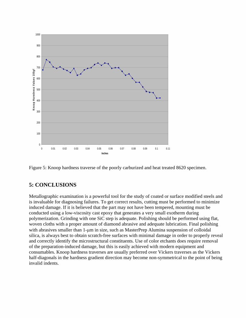
As we often learn more by examining failures, the following example is a poorly carburized and heat treated gear made from 8620 alloy steel that failed early in service. Figure 3 shows that the gear teeth surfaces were decarburized during heat treatment after carburizing resulting in a layer ~15-18 m thick of pearlite with patches of ferrite. Below this layer the structure consists of plate martensite and substantial retained austenite with irregularly dispersed patches with intergranular carbide networks. Figure 4 shows the surface at higher magnification. Figure 5 shows a high magnification view of the carbide networks below the surface within the case. Figure 6 shows a tooth after etching with alkaline sodium picrate (100 mL water, 25 g sodium hydroxide, 2 g picric acid; immerse at 80-100 C for 45 s or more) revealing that the carbides are cementite, as would be expected for this grade. It reveals the erratic presence of these networks, which is rather unusual. Figure 7 shows the influence of the erratic subsurface microstructure upon the Knoop hardness profile. The first data point is slightly below the decarburized surface layer. The matrix contained substantial retained austenite starting below the decarburized layer and ended at a depth of ~800 m (~0.031 inches) which lowered the case hardness locally. The profile is a bit erratic due to the variation in retained austenite and martensite content and whether or not the indent hit the erratically distributed grain boundary carbides. The effective case depth based on the Knoop equivalent to 550 HV is at a depth of ~0.081 inch (~2077 m or 2.1 mm).
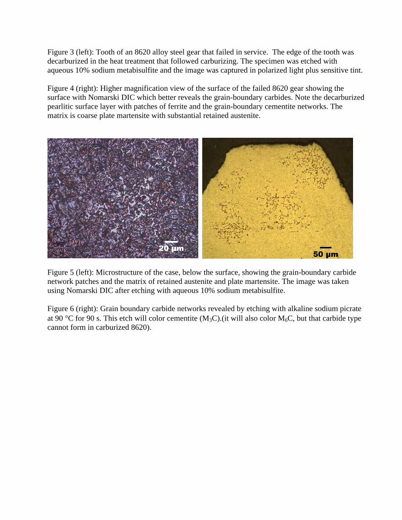
Figure 3 (left): Tooth of an 8620 alloy steel gear that failed in service. The edge of the tooth was decarburized in the heat treatment that followed carburizing. The specimen was etched with aqueous 10% sodium metabisulfite and the image was captured in polarized light plus sensitive tint.
Figure 4 (right): Higher magnification view of the surface of the failed 8620 gear showing the surface with Nomarski DIC which better reveals the grain-boundary carbides. Note the decarburized pearlitic surface layer with patches of ferrite and the grain-boundary cementite networks. The matrix is coarse plate martensite with substantial retained austenite.
Figure 5 (left): Microstructure of the case, below the surface, showing the grain-boundary carbide network patches and the matrix of retained austenite and plate martensite. The image was taken using Nomarski DIC after etching with aqueous 10% sodium metabisulfite.
Figure 6 (right): Grain boundary carbide networks revealed by etching with alkaline sodium picrate at 90 C for 90 s. This etch will color cementite (M3C).(it will also color M6C, but that carbide type cannot form in carburized 8620).
0
100
200
300
400
500
600
700
800
900
1000
0 0.01 0.02 0.03 0.04 0.05 0.06 0.07 0.08 0.09 0.1 0.11
Inches
Kn
oo
p H
ared
nes
s V
alu
es 1
00g
f
Figure 5: Knoop hardness traverse of the poorly carburized and heat treated 8620 specimen.
5: CONCLUSIONS
Metallographic examination is a powerful tool for the study of coated or surface modified steels and is invaluable for diagnosing failures. To get correct results, cutting must be performed to minimize induced damage. If it is believed that the part may not have been tempered, mounting must be conducted using a low-viscosity cast epoxy that generates a very small exotherm during polymerization. Grinding with one SiC step is adequate. Polishing should be performed using flat, woven cloths with a proper amount of diamond abrasive and adequate lubrication. Final polishing with abrasives smaller than 1- m in size, such as MasterPrep Alumina suspension of colloidal silica, is always best to obtain scratch-free surfaces with minimal damage in order to properly reveal and correctly identify the microstructural constituents. Use of color etchants does require removal of the preparation-induced damage, but this is easily achieved with modern equipment and consumables. Knoop hardness traverses are usually preferred over Vickers traverses as the Vickers half-diagonals in the hardness gradient direction may become non-symmetrical to the point of being invalid indents.

6: REFERENCES
1. G. F. Vander Voort, Metallography: Principles and Practice, McGraw-Hill Book Co., NY, 1984, and ASM International, Materials Park, Ohio, 1999.
2. G.F. Vander Voort, E.P. Manilova, J.R. Michael and G.M. Lucas, “Study of Selective Etching of Carbides in Steel,” Fortschritte in der Metallographie 36, Sonderbande der Praktischie Metallographie 36, Deutsche Gesellschaft fur Materialkunde e.V., Frankfurt, Germany, 2004, pp. 255-260.