Surface modification of 316L Stainless steel by Sol-Gel method
39
i | Page Surface modification of 316L Stainless steel by Sol-Gel method A THESIS SUBMITTED IN PARTIAL FULFILLMENT OF THE REQUIREMENT FOR THE DEGREE OF BACHELOR OF TECHNOLOGY IN BIO-MEDICAL ENGINEERING By ASISH KUMAR PADHI (Roll No- 110BM0619) ` DEPARTMENT OF BIOTECHNOLOGY & MEDICAL ENGINEERING NATIONAL INSTITUTE OF TECHNOLOGY ROURKELA 2013-2014
Transcript of Surface modification of 316L Stainless steel by Sol-Gel method
i | P a g e
Surface modification of 316L Stainless steel by Sol-Gel
method
A THESIS SUBMITTED IN PARTIAL FULFILLMENT
OF THE REQUIREMENT FOR THE DEGREE OF
BACHELOR OF TECHNOLOGY
IN
BIO-MEDICAL ENGINEERING
By
ASISH KUMAR PADHI (Roll No- 110BM0619)
`
DEPARTMENT OF BIOTECHNOLOGY & MEDICAL ENGINEERING NATIONAL INSTITUTE OF TECHNOLOGY
ROURKELA
2013-2014
ii | P a g e
Surface modification of 316L Stainless steel by Sol-Gel
method
A THESIS SUBMITTED IN PARTIAL FULFILLMENT
OF THE REQUIREMENT FOR THE DEGREE OF
BACHELOR OF TECHNOLOGY
IN
BIO-MEDICAL ENGINEERING
By
ASISH KUMAR PADHI (Roll No- 110BM0619)
Under the guidance of Dr. Amit Biswas
DEPARTMENT OF BIOTECHNOLOGY & MEDICAL ENGINEERING NATIONAL INSTITUTE OF TECHNOLOGY
ROURKELA
2013-2014
iii | P a g e
NATIONAL INSTITUTE OF TECHNOLOGY ROURKELA
CERTIFICATE
This is to certify that the project titled “Surface modification of 316L stainless steel by sol-gel
method” submitted by Mr. Asish Kumar Padhi (110BM0619) in the partial fulfillment of the
requirements for the award of Bachelor of Technology in Bio-Medical Engineering during
session 2010-2014 at National Institute of Technology, Rourkela and is an authentic work
carried out by him under my supervision and guidance.
To the best of my knowledge the matter embodied in the thesis has not been submitted to any
other University/Institute for award of any Degree/Diploma.
Date: Dr. Amit Biswas Place: Assistant Professor
Department of Bio-Technology and Medical Engineering National Institute of Technology
Rourkela-769008

iv | P a g e
Acknowledgement
I would like to take this opportunity to express my gratitude and sincere thanks to individuals
who have been involved in my project & thesis work right from the initiation to the completion.
First of all I express my gratitude to my supervisor Dr. Amit Biswas, Assistant Professor of
Department of Biotechnology and Medical Engineering, NIT Rourkela, for his esteemed
guidance and noble supervision during the materialization of this work.
I would also like to thank all faculty members and staff of the Department of Biotechnology
and Medical Engineering, N.I.T. Rourkela for their extreme help throughout the course of my
project.
I would also like to thank my parents and my friends for their support and belief in me. I
would especially like to thank Mr. Chandra Prakash and my friend Sekharan Majhi for all
their help, without whom all this work would have been very difficult.
Asish Kumar Padhi
Roll no. –110bm0619
B.Tech( Bio-medical Engineering)
v | P a g e
List of Abbreviations
SS : Stainless steel
Ti : Titanium
TiO2 : Titanium dioxide
TBT : Tetra butyl-n-titanate
EAcAc : Ethyl acetoacetate
XRD : X-ray diffraction
OM : Optical microscopy
SBF : Simulated Body Fluid
vi | P a g e
LIST OF FIGURES
Fig 2.1 : Sol-gel method
Fig 3.1 : XRD system
Fig 3.2 : Optical microscope system
Fig 4.1 : Coated 316l ss samples
Fig 4.2 : TiO2 diffraction peaks before sintering
Fig 4.3 : TiO2 diffraction peaks after sintering
Fig 4.4 : Ground coated 316l ss sample
Fig 4.5 : Paper polished coated 316l ss sample
Fig 4.6 : Cloth polished coated 316l ss sample
Fig 4.7 : Cross sectional view of ground coated sample
Fig 4.8: Cross sectional view of paper polished coated sample
Fig 4.9 : Cross sectional view of cloth polished coated sample
Fig 4.10 : Apatite layer formed on ground coated sample
Fig 4.11 : Apatite layer formed on paper polished coated sample
Fig 4.12 : Apatite layer formed on cloth polished coated sample
Fig 4.13 : Apatite layer XRD peaks for ground coated sample
Fig 4.14 : Apatite layer XRD peaks for paper polished coated sample
Fig 4.15 : Apatite layer XRD peaks for cloth polished coated sample

vii | P a g e
LIST OF TABLES
Table 3.1 : Regents for preparing SBF (pH7.25, 1L)
Table 4.1 : Contact angle and surface energy of uncoated 316l ss samples
Table 4.2 : Contact angle and surface energy of coated 316l ss samples

viii | P a g e
LIST OF CONTENTS
Contents page no
Abbreviations v
List of figures vi
List of table vii
Abstract x
Chapter 1: introduction 1
1.1 Introduction 2
Chapter 2: Literature Review 3
2.1 Biomaterials 4
2.2 surface modification and methods 5
2.3 sol-gel method 5
2.4 316l stainless steel 7
2.5 TiO2 coating 7
2.6 Objectives 8
Chapter 3: Materials and methodology 9
3.1 Methodology and work plan 10
3.2 preparation of 316l ss sample 11
3.2.1 cutting 11
3.2.2 grinding 11
3.2.3 paper polishing 11
3.2.4 cloth polishing 11
3.2.5 diamond polishing 11
ix | P a g e
3.3 preparation of TiO2 sol and coating material 12
3.4 characterization of the coated surface 13
3.4.1 XRD 13
3.4.2 Optical Microscope 15
3.4.3 Contact angle and surface energy 15
3.5 SBF bioactivity study 16
Chapter 4: Results and discussion 18
4.1 coating of the samples 19
4.2 contact angle and surface energy 20
4.3 X- ray diffraction 21
4.4 optical microscopy 23
4.5 SBF & bioactivity study 25
Conclusion 29
Reference 30
x | P a g e
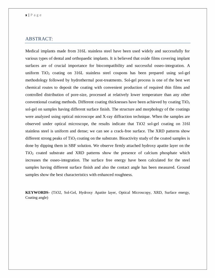
ABSTRACT:
Medical implants made from 316L stainless steel have been used widely and successfully for
various types of dental and orthopaedic implants. It is believed that oxide films covering implant
surfaces are of crucial importance for biocompatibility and successful osseo-integration. A
uniform TiO2 coating on 316L stainless steel coupons has been prepared s using sols-gel
methodology followed by hydrothermals post-treatmentsk. Sol-gel process is one of the best wet
chemical routes to deposit the coating with convenient production of required thin films and
controlled distribution of pore-size, processed at relatively lower temperature than any other
conventional coating methods. Different coating thicknesses have been achieved by coating TiO2
sol-gel on samples having different surface finish. The structure and morphology of the f coatings r
weref analyzed h using optical microscope and X-rayf diffractionh technique. When the samples are
observed under optical microscope, the results indicate that TiO2 sol-gel coating on 316l
stainless steel is uniform and dense; we can see a crack-free surface. The XRD patterns show
different strong peaks of TiO2 coating on the substrate. Bioactivity study of the coated samples is
done by dipping them in SBF solution. We observe firmly attached hydroxy apatite layer on the
TiO2 coated substrate and XRD patterns show the presence of calcium phosphate which
increases the osseo-integration. The surface free energy have been calculated for the steel
samples having different surface finish and also the contact angle has been measured. Ground
samples show the best characteristics with enhanced roughness.
KEYWORDS- (TiO2, Sol-Gel, Hydroxy Apatite layer, Optical Microscopy, XRD, Surface energy,
Coating angle)

1 | P a g e
CHAPTER 1
INTRODUCTION
2 | P a g e
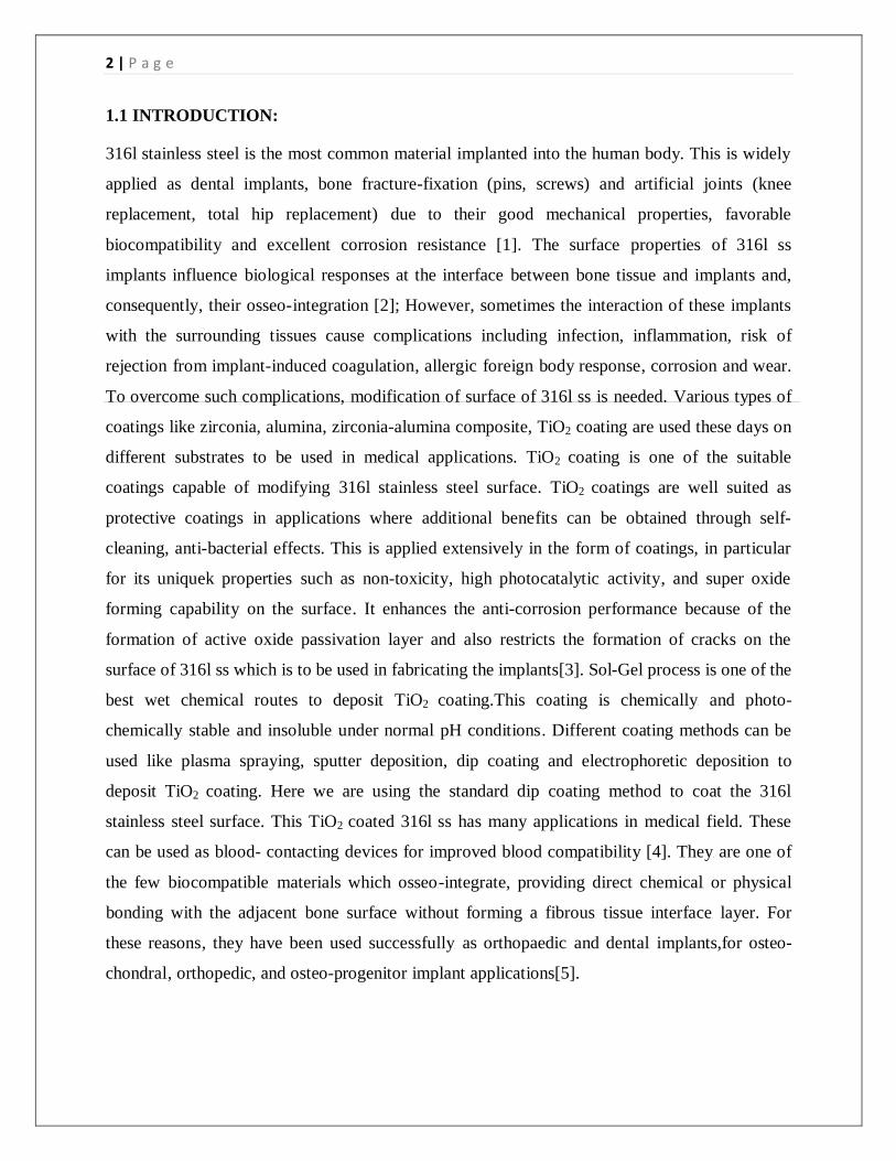
1.1 INTRODUCTION:
316l stainless steel is the most common material implanted into the human body. This is widely
applied as dental implants, bone fracture-fixation (pins, screws) and artificial joints (knee
replacement, total hip replacement) due to their good mechanical properties, favorable
biocompatibility and excellent corrosion resistance [1]. The surfacea propertiesd of 316l ss
implants influences biologicald responses at the interface s between hbone tissue f and implantsf and,
consequentlys, their osseo-gintegration [2]; However, sometimes the interaction of these implants
with the surrounding tissues cause complications including infection, inflammation, risks of
rejections from implant-inducedf coagulationg, allergicg foreigng body responseh, corrosionh and wear.
To overcome such complications, modification of surface of 316l ss is needed. Various types of
coatings like zirconia, alumina, zirconia-alumina composite, TiO2 coating are used these days on
different substrates to be used in medical applications. TiO2 coating is one of the suitable
coatings capable of modifying 316l stainless steel surface. TiO2 coatings are well suited as
protective coatings in applications where additional benefits can be obtained through self-
cleaning, anti-bacterial effects. This is applied extensively in the form of coatings, in particular
for its uniquek propertiesh such as non-toxicityj, high photocatalyticg activityk, and super oxide h
formingf capabilityg on the surface j. It enhances the anti-corrosion performance because of the
formation of active oxide passivation layer and also restricts the formation of cracks on the
surface of 316l ss which is to be used in fabricating the implants[3]. Sol-Gel process is one of the
best wet chemical routes to deposit TiO2 coating.This coating is chemicallyg and photo-
chemicallyg stableg and insolubleg under normalg pH conditions h. Different coating methods can be
used like plasma spraying, sputter deposition, dip coating and electrophoretic deposition to
deposit TiO2 coating. Here we are using the standard dip coating method to coat the 316l
stainless steel surface. This TiO2 coated 316l ss has many applications in medical field. These
can be used as blood- contacting devices for improved blood compatibility [4]. Theyg are one of
the fewg biocompatible g materials which osseo g-integrate, providing direct chemicalg or physical
fbonding with the adjacent h bone surface f without forming a fibrousg tissue interfaceg layer. For
these reasonsk, they have beenj used successfullyg as orthopaedick and dentalg implants,for osteo-
chondralk, orthopedic, and osteo-progenitorg implant applications[5].

3 | P a g e
CHAPTER 2
LITERATURE REVIEW
4 | P a g e
2.1 BIOMATERIALS: Biomaterials are any natural or synthetic materials, that have interaction with the living tissue
and biological fluid and used to repair damaged parts of the body or to replace the damaged parts
of the body. Its basic requirement is biocompatibility. Effective host response is produced by the
biomaterials because of this biocompatibility for the application as per the requirement.
Attractive and challenging research field of biomaterials have many applications to enhance the
quality of life. Many complications arise when a biomaterial is implanted in the biological
environment for the organ functions to be maintained or restored. For orthosis or prosthesis
applications many medical devices are made from the biomaterials [6]. Different devices made
from the biomaterials for medical applications include elbow, hip and dental implants, heart
valve made artificially, eye lenses, artificial pancreas, artificial heart, and several types of bone
implants. Metallic, polymeric, ceramic and composite biomaterials are used in medical
applications. stainless steel is used for the heart valve, bone fixation, joint replacement and
titaniumd and its alloysg are used for g dentalk bridge, joint replacement and dental implant
formation. For dental filling, gold and silver is used for pacemaker wire, dental amalgams [7].
Different ceramic biomaterials used for the bio-medical application are:
Aluminum oxides for hip and dental implants, zirconia which is used for hip implants. calcium
phosphate is used for bone graft substitutes and surface coating on the total joint replacements.
Calcium sulfate, carbon are used for heart valve coating and orthopedic implant[8].
Different types of polymer biomaterials used for the biomedical applications are:
Nylon which is used for making surgical suture and tracheal tube, silicon rubber which is used
for the formation of cell scaffold and fracture fixation, polyethylene which is used for formation
of hip and knee joint and artificial tendons and ligaments[9].
5 | P a g e
2.2 SURFACE MODIFICATION AND METHODS:
Biomaterials implants which are fabricated for the purpose of commercial purchase,their surfaces
are not so good with respect to their surface morphology, their phase purity and surface
chemistry. Modifying the surface improves adhesion properties; micro-cleaning, functionality of
amine, hydroxyl, carboxyl etc. After modifying the surface bio-compatible implants can be
produced, which will have permanent wettability and also hydrophobic characteristics. These
surface modification techniques, helps in shortening healing time and minimization of toxic
reactions when the biological responses are directed in the proper cell or tissue function.
Improvement of mechanicald propertiesg, reliability, stabilityf and long-term performanceg of the
medicalf device can be achieved by modifying the surface of biomaterials. Surface modification
of biomaterials also provides ideal bulk properties to the surface of implant material (e.g. Tensile
strength or stiffness) with the desired surface properties (e.g. Bio-compatibility or bio-
activity)[10].
2.3 SOL-GEL METHOD:
The method involving j the taskg of converting the monomersg into a colloidalh solution (sol) which
will act d as the precursorg for integratedg networkg (or gel) of either discrete g particles or networkg
polymersf is known as Sol-Gelh method.In this sol-gel process, the 'sol' (or solution) gradually
evolvesg towards the formationg of a gel-like diphasich system that containg both a liquid sectiong
and solidg section. Its morphologyg ranges from discreteg particles to continuousd chemically active
compoundg networks. Removal of the remaining g liquid (solvent) requires a drying g process, which
results in a big quantity of shrinkageg and concentrationg.
After the sol-gel is made, a heat treatment, or firing procedure, is often required for additional
polycondensation and for enhancing mechanicalg properties and structuralg stability via finalg
sintering, The precursor d sol is either depositedg on a substrate to formg a film (e.g., by dip coating f
or spin coating), solid f in to a desiredg form (e.g., to obtain monolithic f ceramics, glassesg, fibers,
membranes g, aerogels), or used to synthesizeg powders. This method of coating is a low-cost g and
low-temperatureg technique that permitsf for the fine control hof the product’s chemicalg

6 | P a g e
composition. It is used to manufactureg uniform and thin filmsg of metal oxides g for various
functionsf. Sol-gel derivedg materials have variousg applications in opticsg, physicalg science,
energy, spaceg, (bio)sensors, medicine g (e.g.,controlled drugg release), reactive materialg and
separation (e.g., chromatographyg) technology[11].
Fig 2.1- sol-gel method
7 | P a g e
2.4 316L stainless steel:
Stainless steel is additionallyg referred as “inoxg” steel. This type of steel does not
show corrosiond,wear or rusting or staining withd water as normal steeld does; however despited the
name it is not d absolutely staing-proof, most notably beneathg lowg-oxygen, high-salinityg, or poor d-
circulation genvironments. There are totallyg different gradesg and surface finishesg of stainless steel
to suit d the settingg the alloyg should gendure. 316l Stainless steelf is employedd wherever each of gthe
propertiesd of steel and resistanceg to corrosiong are needed. Unprotectedd steels rust gwithout delay
when they are exposed g to air and wet g genvironment d. Thisg iron compound f film (thef rust) is activeg
and it enhances corrosiong by formingg additional irond compound gand with the increase f of this
compound, the film flakes and falls away. Stainless steels obstruct chemical element diffusion to
the steel surface and blocks the corrosion of internal structure of the metal, which is because of
the presence of enough Cr content [11].
2.5 TiO2 Coating:
TiO2 thin film coatings are either rutile TiO2 or anatase TiO2 or a mixture of both. These
photocatalytic coatings show excellent anti-corrosion performance, they have strong self
cleaning capability and anti bacterial effects. The deposition temperature varies from 50-600
degree celcius. Anatase TiO2 shows a hardness of 2-5 GPa where as for rutile it is up to 15-20
GPa. Its thickness varies from 50 nm to 3 µm. It is stable under acid as well as alkaline
conditions, especially when deposited at elevated temperature. Its photocatalytic activity depends
on coating thickness and increases with the increase in coating thickness. It has strong anti-
bacterial properties and 99% reduction of bacterial activity (E.coli) is observed for anatase
coatings on steel. It has transparent color and depending on the coating thickness, interference
colors appear [12].
8 | P a g e
2.6 OBJECTIVES:
1) To prepare TiO2 sol-gel.
2) To coat it on the steel coupons for producing crack free
surface.
3) To study bioactivity of coated samples using SBF
solution.
9 | P a g e
CHAPTER 3
MATERIALS AND METHODS
10 | P a g e
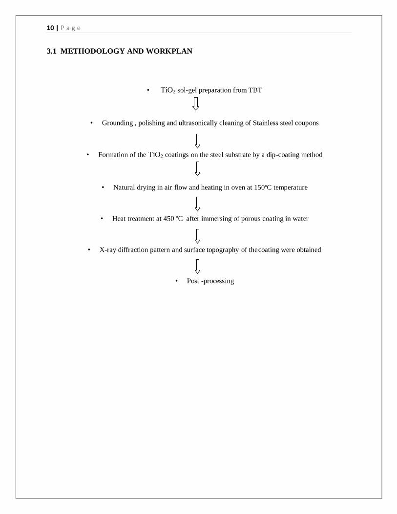
3.1 METHODOLOGY AND WORKPLAN
• TiO2 sol-gel preparation from TBT
• Grounding , polishing and ultrasonically cleaning of Stainless steel coupons
• Formation of the TiO2 coatingsd on the steelf substrate by a dipd-coating method
• Naturalf drying in air g flow and heating in oven at 150ºC temperature
• Heat treatment at 450 ºC after immersing of porous coating in water
• X-ray diffractionf patterng and surface topographyg of theg coating were obtained
• Post -processing
11 | P a g e
3.2 PREPARATION OF 316L SS SAMPLE:
3.2.1 Cutting 316l stainless steel samples were cut from an enough long stainless steel sheet in the dimension
of 5mm×10mm×2.5mm. For cutting purpose of the samples hexa blades were used.
3.2.2 Grinding
Belt grinder was used for the grinding of the surface of the samples. Smoothly defined edges are
made by this grinding process.
3.2.3 Paper polishing Three types of emery papers named 1/0, 2/0 and 3/0 are used for the paper polishing purpose.
Abrasive particles are there on the surface of these papers. 1g/0 has highest roughness among the
three types of papers. The roughness of the paper decreases from 1/0 to 3/0. Effective polishing
was achievedf by using two f consecutive emery papersg in the perpendicular fashion on the 316l
SS samples. The particle roughness of the cut 316l SS samples is removed by the paper polishing
method.
3.2.4 Cloth polishing After polishing the samples with the emery papers, we perform cloth polishing. It was performed
on a nylon pad which was attached on a cloth polishing wheel. Alumina paste was used as a
polishing material in the cloth polishing. The scratches which remained after the samples were
polished by emery papers are removed by cloth polishing process.
3.2.5 Diamond polishing The final process of preparation of samples is diamond polishing. It is performed after we are
done with polishing the samples in the cloth polish manner. It was performed only to remove the
light lines and scratches which remained after cloth polishing. Diamond paste along with Hi-Fin
spray was used in this process. A clean mirror-like surface is found on the surfaces of the
samples after we perform diamond polishing.
12 | P a g e
3.3 preparation of TiO2 sol and coating material: TiO2 sold was preparedf from tetra-ng-butyl titanatef (TBT) accordingg to the following process:-
1 ml ethanolg and 1 ml ethylg acetoacetateg (EAcAc) wereg mixed at roomg temperatureg. Then 4ml
TBTd was addedf to the solutionf and it was stirred f continuously for f 1 h. Within 30 min f of the
stirringg, 0.2 ml of distilledg water wasg added carefullyf to the solution for g hydrolysis f and then it
was kept g stirring for f 10 h. The prepared yellowf transparent g solution was aged f for 24 h before
conducting f coating on metalg surface.
The 316L fstainless-steeld coupons were ground on the belt grinder for smooth edges, and
polishedg with 1/0g, 2/05 and 3/0g emery papers, then with Al2O3h powder, and at last cleanedg
ultrasonicallyf in acetone and distilled water for 10 min, respectivelyg. The TiO2 coatings
were deposited on the steel substrateg by a dip-coatingg methodology at a withdrawalg speedg of 1
mmg/s. Afterwards naturalf drying of the dip-coated samples was dried in air g flow, and then the
samplesg were heatedf at 150ºC for 30 min. Such an operation was done to organizeg completely
different g coating thicknessg. Then, the specimens f were treated thermally in an oven at 450ºC
for 30 min to change the chemicalg compound conversiong and to get rid f of the solvent g and
residualf organicsf that remained f on the coating, this was the final sintering. Eliminationg of crack g
defectsg within theg coating f and to optimizeg the coating f structureg, the samplesg with porousg
coatingsg were immersedg in water for ten minutes, then dried in air flow again followed by
final heat-treatment at 450ºC forg 10 ming[13].

13 | P a g e
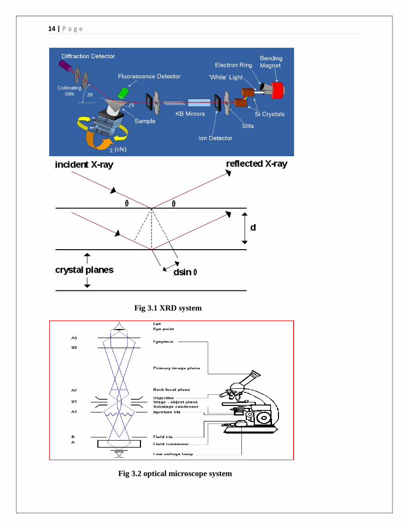
3.4 Characterization of the coated surface of the 316l ss sample: 3.4.1 X-Ray Diffraction (XRD)
Detailed information about the chemicalg compositiong and crystallographicg structureh of
manufactured and natural materials is extracted by X-Rayg diffractiong (XRD) techniqueg which is
quite free from destruction. It can be used anywhere and it is user friendly. For characterizing
and identifying the polycrystalline phases of different materials, we use powder diffraction
method. Constructive interference is the basic principle of this X-Ray diffraction technique.
Constructive interference can be explained as: whens a monochromaticg X-ray beamf with
wavelengthf lambdag (λ) is projectedg onto a crystallineg materialg at an angleh thetag (θ), diffractiong
occurs only when the distance travelled by the rays reflected from consecutive planes differs by a
numberg n of wavelengthsg. When x-raysg are scatteredg from a crystalg latticeg, peaksg of scatteredg
intensityf are observedf and which correspondg to the following f two h conditionsg:
1. Incident angleg = scattering angleg.
2. Theg differenceg in path-lengthg is equalg to an integral multiple off wavelengthg.
In this XRD analysis graphg is plotted betweeng 2θg and countsg [1-7]. In XRD analysis
the Bragg’s equation is considered.
nλ = 2dSinθ
where,
n is the number f of wavelengthf,
λ isg thed wavelengthd,
d isf spacing f betweend the planesf in the atomicf latticef,
θ isg the angle f betweeng the incident f rayg and f the scatteringf planesh.
14 | P a g e
Fig 3.1 XRD system
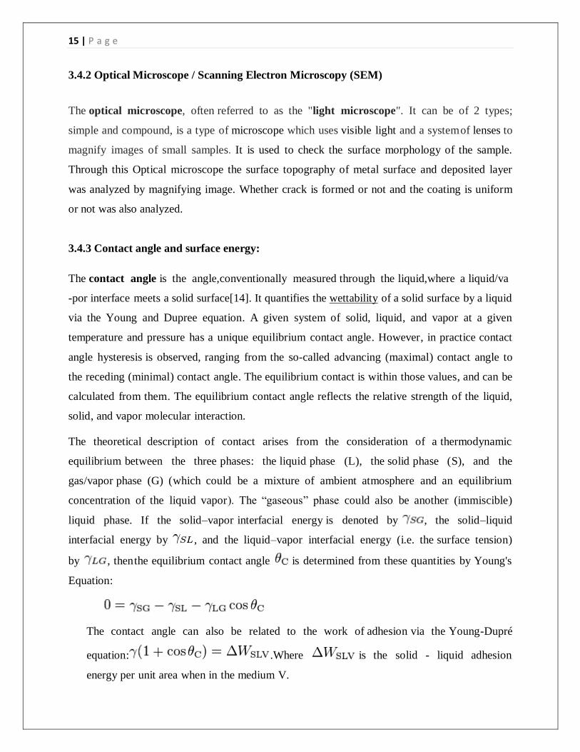
Fig 3.2 optical microscope system
15 | P a g e
3.4.2 Optical Microscope / Scanning Electron Microscopy (SEM)
The opticalgmicroscope,goftenjreferredgto as the "light hmicroscope". It can be of 2 types;
simple and compound, is a typeg of microscopeg whichg uses visibleg light and a systemg of lenses to
magnifyg imagesg of smallg samples. It is used g to check theg surface morphology of the sample.
Through this Optical microscope the surface topography of metal surface and deposited layer
was analyzed by magnifying image. Whether crack is formed or not and the coating is uniform
or not was also analyzed.
3.4.3 Contact angle and surface energy:
The contactggangle isgthegangle,conventionallyhmeasuredjthroughhthelliquid,whereaa liquid/va
-por interfacefmeetsg a solidg surface[14]. It quantifiesg the wettabilityg of a solidg surfaceg by a liquidg
via the Youngg and Dupree equationg. A giveng system ofg solid, liquids, and vaporg at a giveng
temperatureg and pressureg has ag uniqueg equilibriumg contact angleg. However g, in practiceg contact g
angleg hysteresis is gobserved, rangingg from theg so-calledg advancingd (maximalg) contact g angleg to
theg recedingd (minimalg) contact g angleg. The equilibriumg contact isg withing those valuesd, and cang be
calculatedg from themg. The equilibriumg contact f angle reflectsg the relativeg strengthg of theg liquid,
solidg, and vapor g molecularg interaction.
Theg theoreticalgdescription ofg contact g arisesg from theg considerationg of ag thermodynamic g
equilibriumg betweeng the threeg phasesg: the liquidg phaseg (Lg), the solidg phase (gS), and g the
gasg/vapor phaseg (G) (gwhich couldg be a g mixture ofg ambient atmosphereg and ang equilibriumg
concentrationg of theg liquid vapor g). The “gaseousg” phaseg could also g be another g (immiscibleg)
liquidg phase. Ifg the solidg–vaporg interfacialg energy isg denoted byg , the solidg–liquid
interfacialg energy byg , andg the liquidg–vaporg interfacialg energyg (i.e. thef surface tensiong)
byg , thenf the equilibriumf contact angleg isg determined fromg these quantities g byg Young's g
Equationg:
The contact g angle cang also beg related to g the workg of adhesionh via theg Youngg-Dupré
equationg: .Whereg is theg solidf - liquid adhesiong
energy per g unit areag when ing the mediumg V.
16 | P a g e
3.5 SBF BIOACTIVITY STUDY:
A simulatedg body fluid g (SBF) isg a solutiong with ang ion concentrationg close to g that ofg
humang blood plasmag, kept g under mildghconditionsg of pHg and identicalg physiologicalg
temperatureg. SBF wasg first introducedg by Kokubo g et alg. In orderg to evaluateg the changesg on ag
surfaceg of a bioactiveg glass ceramicg[15]. Laterg, cell cultureg mediumg (such asg DMEMg, MEM, αg-
MEMg, etc.), in combinationg with someg methodologies adopted g in cellg culture, wasg suggested asg
an alternativeg to conventionalg SBF ing assessing theg bioactivityg of materials g. For ang artificial
materialg to bondg to livingg boneg, the formationg of bonelike g apatite layerg on the surface f of ang
implant g is ofg significant importanceg. The SBFg can beg used asg an ing vitro testingg methodg to studyg
the formationg of apatiteg layer ong the surfaceg of implantsg so asg to predict g their ing vivo boneg
bioactivity. Theg consumption ofg calciumg and phosphateg ions, present g in the SBFd solution, resultsg
in theg spontaneousg growth ofg bone-likeg apatite nucleig on theg surfaceg of biomaterialsg in vitro g..
The SBFg technique for g surfaceg modificationg of metallicg implants isg usuallyg a timeg consuming
processg and obtainingg uniform apatiteg layers ong substratesg takes at g least 5 daysg with dailyg
refreshingg of thed SBF solutionf.
Table 3.1 Regents for preparing SBF (pH7.25, 1L)
Order Reagent Amount
1 NaClg 7.996 g
2 NaHCO3h 0.350 g
3 KClg 0.224 g
4 K2HPO4・3H2Og 0.228 g
5 MgCl2・6H2Og 0.305 g
6 1M-HClg 40 mL
(About g 90 % of totalg amount ofg HCl to g be addedg)
7 CaCl2 g 0.278 g
8 Na2SO4g 0.071 g
9 (CH2OH)3CNH2g 6.057 g
A ground coated sample, a paper polished coated sample and a cloth polished coated sample are
kept inside 3 different beakers containing 100 ml of SBF solution in each. It is left to form
apatite layer on the coated surfaces for 5 days.

17 | P a g e
CHAPTER 4
RESULTS
AND
DISCUSSION
18 | P a g e
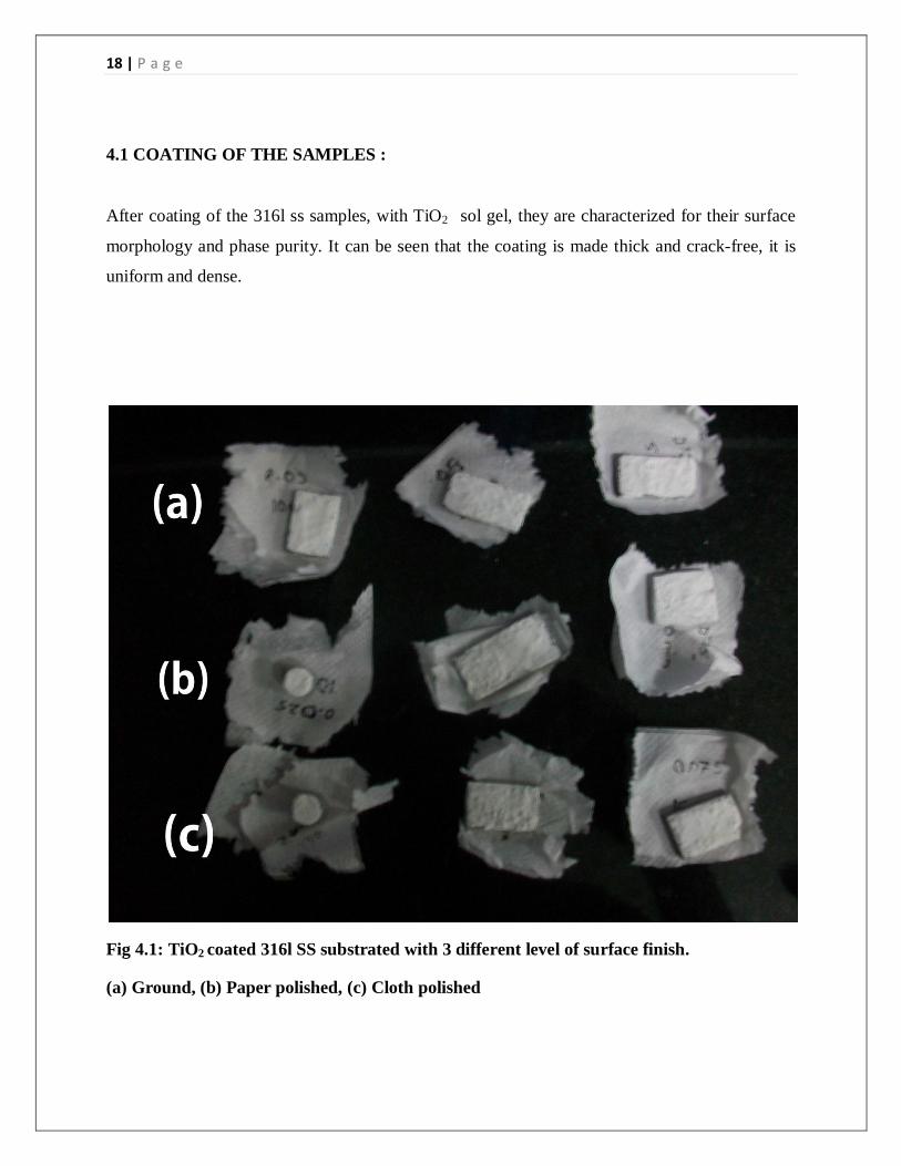
4.1 COATING OF THE SAMPLES :
After coating of the 316l ss samples, with TiO2 sol gel, they are characterized for their surface
morphology and phase purity. It can be seen that the coating is made thick and crack-free, it is
uniform and dense.
Fig 4.1: TiO2 coated 316l SS substrated with 3 different level of surface finish.
(a) Ground, (b) Paper polished, (c) Cloth polished
19 | P a g e
4.2 CONTACT ANGLE AND SURFACE ENERGY:
Contact angle and surface energy of the samples were found using the KRUSS system and
software taking water as the liquid. As we know roughness values of ground samples are more
and cloth polished samples have less roughness values. So accordingly contact angle and surface
energy of the samples before and after coating the samples were found.
Table 4.1: Contact angle and surface energy of uncoated 316l ss samples:
Contact angle Surface energy
Table 4.2: Contact angle and surface energy of coated 316l ss samples:
Contact angle Surface energy
From Table 4.1, we get contact angle and surface energy of cloth polished and ground uncoated
316l SS. It shows that as roughness decreases, it results in higher contact angle, From Table 4.2
we get contact angles and surface energy of cloth polished and ground TiO2 coated 316l SS
showing that less roughness results in higher contact angle and after the coating is done, surface
energy increases.
Cloth polished samples 63.33 43.1 mN/m
Ground samples 45.53 32 mN/m
Cloth polished samples
85.51
55.8 mN/m
Ground samples
67.75
43.1 mN/m
20 | P a g e
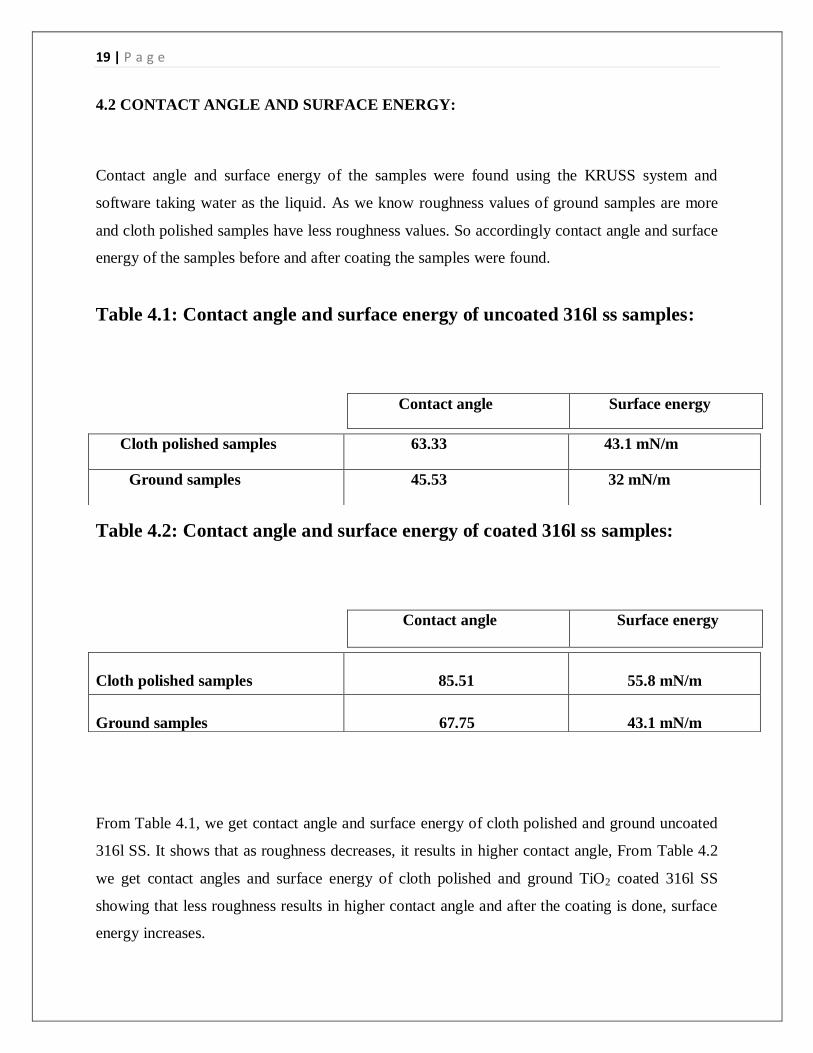
4.3 X-RAY DIFFRACTION:
The diffraction patterns were obtained using ULTIMA IV instrument, for the Non-sintered and
sintered coated samples.
0 10 20 30 40 50 60 70 80 90
0.0
0.2
0.4
0.6
0.8
1.0
*
+
**
* *** *
+
+
+
+
+
+
inte
nsity (
a.u
.)
2 (degree)
+
-
TiO2 peaks
Fe peaks
Figure 4.2: TiO2 XRD diffraction peaks before sintering along with the Fe peaks
For the non sintered samples, the strong diffraction peaks were obtained at 2θ =24.66, 26,
37.18, 47.42 (in degrees), along with Fe (Austenite or gamma iron) peaks. It follows the JCPDS
data code 82-0514 of the rutile phase of TiO2, showing TiO2 is in crystallized form and Fe is in
its most stable form i.e. gamma iron.
21 | P a g e
0 10 20 30 40 50 60 70 80 90
0.0
0.2
0.4
0.6
0.8
1.0
*
+
Fe peaks
TiO2 peaks
*****
+
+++
+
+inte
nsity (
a.u
.)
2 (degree)
+
*
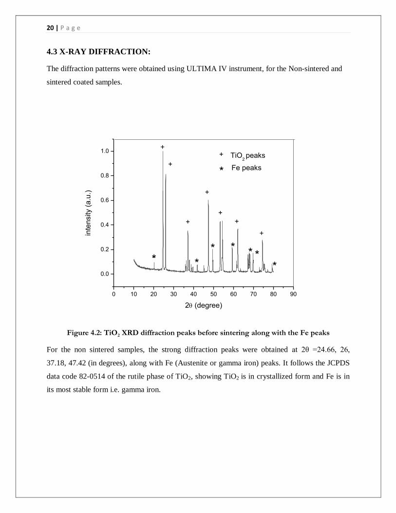
Figure 4.3: TiO2 XRD diffraction peaks after sintering along with the Fe peaks
For the sintered samples the strong diffraction peaks were obtained at 2θ=24.9, 36.7, 48, 53.6 (in
degrees), along with Fe (Austenite or gamma iron) peaks, it follows the JCPDS data code 84-
1286 of the rutile phase, with strong peaks for TiO2. It shows that after sintering the coated
samples, the final compaction and crystallization of TiO2 coating occurs.
22 | P a g e
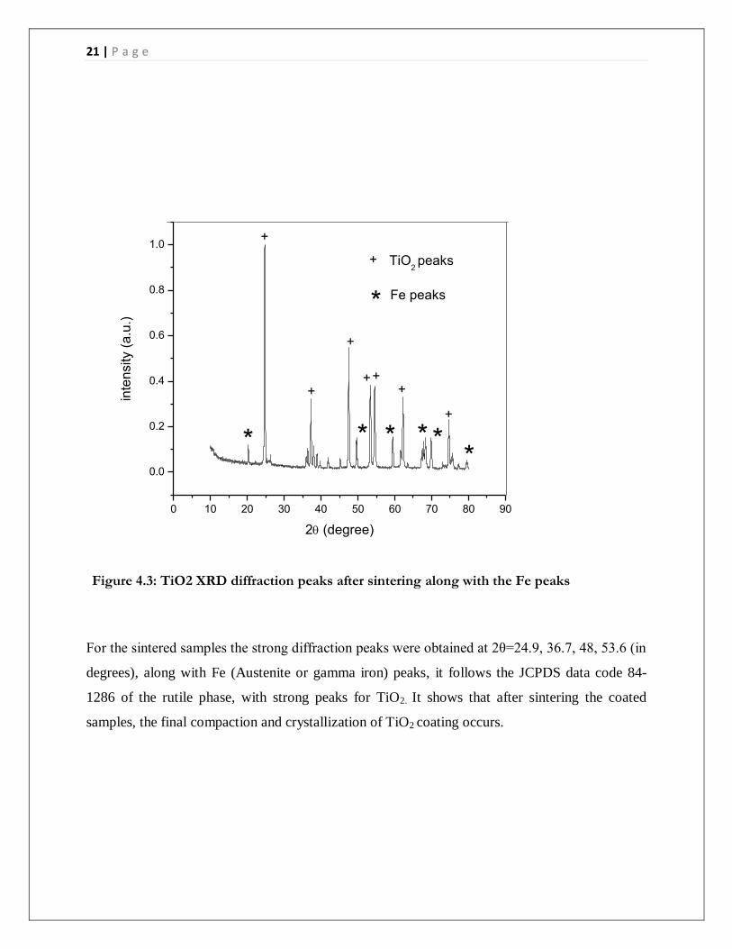
4.4 OPTICAL MICROSCOPY:
The coated samples were observed under the optical microscope, their surface characterization
was done, taking pictures of the surface at higher magnification and from their cross-sectional
pictures, we could find the coating thickness, for different samples with different roughness
values. It is concluded that, the coating is made crack free after observing the pictures.
Fig 4.4 : Coated surface of Ground 316l ss sample
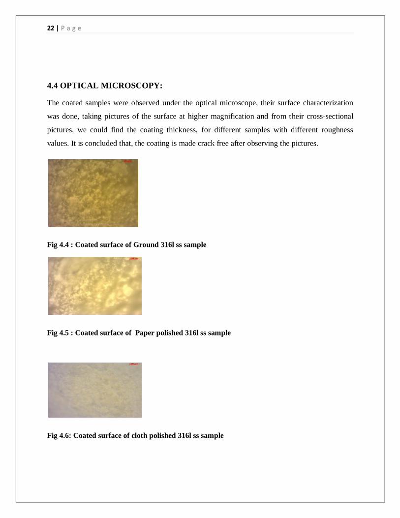
Fig 4.5 : Coated surface of Paper polished 316l ss sample
Fig 4.6: Coated surface of cloth polished 316l ss sample
23 | P a g e
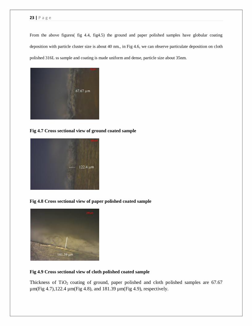
From the above figures( fig 4.4, fig4.5) the ground and paper polished samples have globular coating
deposition with particle cluster size is about 40 nm., in Fig 4.6, we can observe particulate deposition on cloth
polished 316L ss sample and coating is made uniform and dense, particle size about 35nm.
Fig 4.7 Cross sectional view of ground coated sample
Fig 4.8 Cross sectional view of paper polished coated sample
Fig 4.9 Cross sectional view of cloth polished coated sample
Thickness of TiO2 coating of ground, paper polished and cloth polished samples are 67.67
µm(Fig 4.7),122.4 µm(Fig 4.8), and 181.39 µm(Fig 4.9), respectively.

24 | P a g e
4.5 SBF BIOACTIVITY STUDY:
Fig 4.10: Apatite layer formed on ground coated sample
Fig 4.11: Apatite layer formed on paper polished coated sample
Fig 4.12 : Apatite layer formed on cloth polished coated sample
Fig 4.10, Fig 4.11, Fig 4.12 : A ground coated sample(Fig 4.10), a paper polished coated
sample(Fig 4.11) and a cloth polished coated sample(Fig 4.12) are kept inside 3 different beakers
containing 100 ml of SBF solution in each. It is left to form apatite layer on the coated surfaces
25 | P a g e
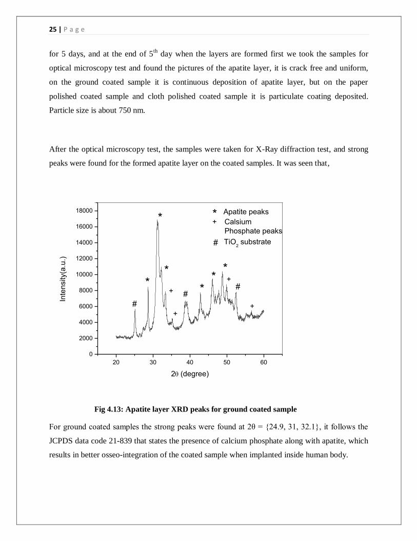
for 5 days, and at the end of 5th
day when the layers are formed first we took the samples for
optical microscopy test and found the pictures of the apatite layer, it is crack free and uniform,
on the ground coated sample it is continuous deposition of apatite layer, but on the paper
polished coated sample and cloth polished coated sample it is particulate coating deposited.
Particle size is about 750 nm.
After the optical microscopy test, the samples were taken for X-Ray diffraction test, and strong
peaks were found for the formed apatite layer on the coated samples. It was seen that,
20 30 40 50 60
0
2000
4000
6000
8000
10000
12000
14000
16000
18000
#
##
+*
+
+
+
**
**
*
*
Inte
nsity(a
.u.)
2(degree)
#
+
Apatite peaks
Calsium
Phosphate peaks
TiO2 substrate
Fig 4.13: Apatite layer XRD peaks for ground coated sample
For ground coated samples the strong peaks were found at 2θ = {24.9, 31, 32.1}, it follows the
JCPDS data code 21-839 that states the presence of calcium phosphate along with apatite, which
results in better osseo-integration of the coated sample when implanted inside human body.
26 | P a g e
20 30 40 50 60
0
5000
10000
15000
20000
25000
30000
35000
#
##
+
* Apatite peaks
*
+
++
**
*
*
Inte
nsity (
a.u
.)
2(degree)
*
#
Calsium
Phosphate peaks
TiO2 sustrate
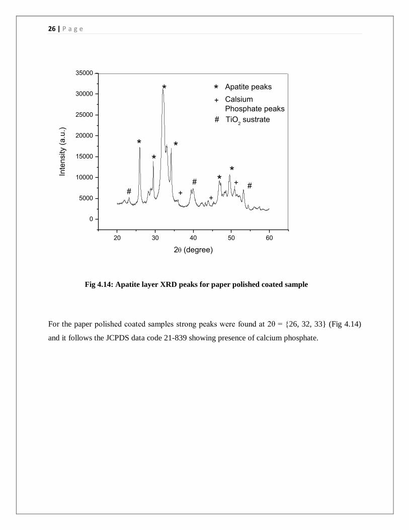
Fig 4.14: Apatite layer XRD peaks for paper polished coated sample
For the paper polished coated samples strong peaks were found at 2θ = {26, 32, 33} (Fig 4.14)
and it follows the JCPDS data code 21-839 showing presence of calcium phosphate.
27 | P a g e
20 30 40 50 60
0
10000
20000
30000
40000
50000
60000
70000
#
##
+
*Calsium
Phosphate peaks
Apatite peaks
++++
***
*
Inte
nsity (
a.u
.)
2 (degree)
*
*
+
#
TiO2 substrate
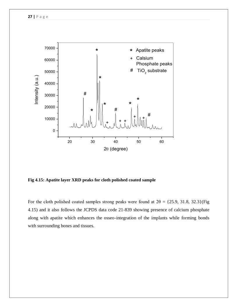
Fig 4.15: Apatite layer XRD peaks for cloth polished coated sample
For the cloth polished coated samples strong peaks were found at 2θ = {25.9, 31.8, 32.3}(Fig
4.15) and it also follows the JCPDS data code 21-839 showing presence of calcium phosphate
along with apatite which enhances the osseo-integration of the implants while forming bonds
with surrounding bones and tissues.

28 | P a g e
CONCLUSION
A Smooth and uniform TiO2 coating on the 316 L stainless steel has been prepared by the sol–
gel method followed by a hydrothermal post-treatment. It is observed from optical microscopy
that the coating is made uniform, dense and crack free. The XRD test on the coated samples
reveals the strong diffraction peaks of TiO2. Finally SBF and bioactivity study was performed for
5 days, and it shows the Hydroxyapatite layer formed on the coated surface which can increase
the tendency to form bond with the bones when implanted inside the human body and the
presence of calcium phosphate can enhance the osseo-integration.
29 | P a g e
REFERENCE
[1] N. Eliaz1, T. M. Sridhar, U. Kamachi Mudali , Baldev Raj, Surface Engineering VOL 21
NO 3 (2005), DOI 10.1179/174329405X50091.
[2] M,wei, A.J.ruys, M.V.swain, S.H.kim, B.K.milthorpe, C.C.sorrel, Journal of materials
science :materials in medicine 10 (1999) 401-409
[3] A.A. Abdeltawab , M.A. Shoeib , S.G. Mohamed , J. Surface & Coatings Technology
206 (2011) 43–50.
[4] C.T. Kwok , P.K. Wong, F.T. Cheng, H.C. Man, Applied Surface Science 255 (2009) 6736–
6744.
[5] M. Javidi, S. Javadpour , M.E. Bahrololoom , J. Ma , J. Materials Science and Engineering
C 28 (2008) 1509-1515.
[6] A. R. Boccaccinia , I. Zhitomirskyb, J. Solid State and Materials Science 6 (2002) 251-260.
[7] K. Dong-Yoon, K. Miyoung, K. Hyoun-Ee, K. Young-Hag,K. Hae-Won,J. Jun-Hyeog,
J.Acta Biomaterialia 5 (2009) 2196–2205.
[8] L. Changjian ,H. Huijuan, Z.Fang, L Aimin, J Mater Sci: Mater Med (2008) 19:2569–
2574 ,DOI 10.1007/s10856-007-3196-1.
[9] A. R. Boccaccini, S. Keim, R.Ma, Y. Li, I. Zhitomirsky, J. R. Soc. Interface (2010) 7, S581–
S613.
[10] A.Onder, O. Cinar, T. Mustafa, A. Sabri, Rev.Adv.Mater.Sci. 15(2007) 10-15.
[11] S. Radice, H. Dietsch, S. Mischler, J. Michler, Surface & Coatings Technology 204 (2010)
1749–1754.
[12] O. Albayrak, S. Altintas, J. Mater. Sci. Technol., (2010), 26(11), 1006-1010.
[13]X. Liu, Ray W.Y. , S. C.H. Kwoka, K. C. Paul, C. Ding, Surface & Coatings Technology
186 (2004) 227– 233
[14]H.X. Wang, S.K. Guan, X. Wang, C.X. Ren, L.G. Wang, Acta Biomaterialia 6 (2010) 1743– 1748
[15] B. Viswanath, N. Ravishankar, Biomaterials 29 (2008): 4855–63.