SURFACE ISSUED VEHICLE J2190 …read.pudn.com/downloads219/ebook/1030386/SAE_J2190.pdf4.3.2...
63
SAE Technical Standards Board Rules provide that: “This report is published by SAE to advance the state of technical and engineering sciences. The use of this report is entirely voluntary, and its applicability and suitability for any particular use, including any patent infringement arising therefrom, is the sole responsibility of the user.” SAE reviews each technical report at least every five years at which time it may be reaffirmed, revised, or cancelled. SAE invites your written comments and suggestions. QUESTIONS REGARDING THIS DOCUMENT: (412) 772-8512 FAX: (412) 776-0243 TO PLACE A DOCUMENT ORDER; (412) 776-4970 FAX: (412) 776-0790 SAE WEB ADDRESS http://www.sae.org Copyright 1997 Society of Automotive Engineers, Inc. All rights reserved. Printed in U.S.A. SURFACE VEHICLE 400 Commonwealth Drive, Warrendale, PA 15096-0001 RECOMMENDED PRACTICE Submitted for recognition as an American National Standard J2190 ISSUED JUN93 Issued 1993-06-25 ENHANCED E/E DIAGNOSTIC TEST MODES TABLE OF CONTENTS 1. Scope ....................................................................................................................................................... 4 2. References ............................................................................................................................................... 4 2.1.1 SAE Publications ...................................................................................................................................... 4 2.1.2 ISO Publications ....................................................................................................................................... 4 2.1.3 California ARB Documents ....................................................................................................................... 4 2.1.4 Federal EPA Documents .......................................................................................................................... 4 3. Definitions ................................................................................................................................................. 4 4. Technical Requirements ........................................................................................................................... 5 4.1 Test Mode Values ..................................................................................................................................... 5 4.2 Physical Addressing ................................................................................................................................. 6 4.3 Miscellaneous Requirements ................................................................................................................... 6 4.3.1 Message Response Time ......................................................................................................................... 6 4.3.2 Automatic Return to Normal Operation .................................................................................................... 7 4.3.3 Diagnostic Message Length ..................................................................................................................... 7 4.3.4 Message Response.................................................................................................................................. 7 5. Test Modes ............................................................................................................................................... 8 5.1 Modes $00 through $0F - Physically Addressed SAE J1979 Messages .................................................. 8 5.2 Mode $10 - Initiate Diagnostic Operation ................................................................................................. 9 5.2.1 Functional Description .............................................................................................................................. 9 5.2.2 Message Data Bytes ................................................................................................................................ 9 5.3 Mode $11 - Request Module Reset .......................................................................................................... 9 5.3.1 Functional Description .............................................................................................................................. 9 5.3.2 Message Data Bytes .............................................................................................................................. 10 5.4 Mode $12 - Request Diagnostic Freeze Frame Data ............................................................................. 10 5.4.1 Functional Description ............................................................................................................................ 10 5.4.2 Message Data Bytes .............................................................................................................................. 11 5.5 Mode $13 - Request Diagnostic Trouble Code Information .................................................................... 11 5.5.1 Functional Description ............................................................................................................................ 11 5.5.2 Message Data Bytes .............................................................................................................................. 13 5.6 Mode $14 - Clear Diagnostic Information ............................................................................................... 14
Transcript of SURFACE ISSUED VEHICLE J2190 …read.pudn.com/downloads219/ebook/1030386/SAE_J2190.pdf4.3.2...

SAE Technical Standards Board Rules provide that: “This report is published by SAE to advance the state of technical and engineering sciences. The use of this report is entirelyvoluntary, and its applicability and suitability for any particular use, including any patent infringement arising therefrom, is the sole responsibility of the user.”
SAE reviews each technical report at least every five years at which time it may be reaffirmed, revised, or cancelled. SAE invites your written comments and suggestions.
QUESTIONS REGARDING THIS DOCUMENT: (412) 772-8512 FAX: (412) 776-0243TO PLACE A DOCUMENT ORDER; (412) 776-4970 FAX: (412) 776-0790
SAE WEB ADDRESS http://www.sae.org
Copyright 1997 Society of Automotive Engineers, Inc.All rights reserved. Printed in U.S.A.
SURFACEVEHICLE
400 Commonwealth Drive, Warrendale, PA 15096-0001RECOMMENDEDPRACTICE
Submitted for recognition as an American National Standard
J2190ISSUEDJUN93
Issued 1993-06-25
ENHANCED E/E DIAGNOSTIC TEST MODES
TABLE OF CONTENTS
1. Scope ....................................................................................................................................................... 4
2. References ............................................................................................................................................... 42.1.1 SAE Publications ...................................................................................................................................... 42.1.2 ISO Publications ....................................................................................................................................... 42.1.3 California ARB Documents....................................................................................................................... 42.1.4 Federal EPA Documents .......................................................................................................................... 4
3. Definitions................................................................................................................................................. 4
4. Technical Requirements ........................................................................................................................... 54.1 Test Mode Values ..................................................................................................................................... 54.2 Physical Addressing ................................................................................................................................. 64.3 Miscellaneous Requirements ................................................................................................................... 64.3.1 Message Response Time......................................................................................................................... 64.3.2 Automatic Return to Normal Operation .................................................................................................... 74.3.3 Diagnostic Message Length ..................................................................................................................... 74.3.4 Message Response.................................................................................................................................. 7
5. Test Modes ............................................................................................................................................... 85.1 Modes $00 through $0F - Physically Addressed SAE J1979 Messages.................................................. 85.2 Mode $10 - Initiate Diagnostic Operation ................................................................................................. 95.2.1 Functional Description.............................................................................................................................. 95.2.2 Message Data Bytes ................................................................................................................................ 95.3 Mode $11 - Request Module Reset.......................................................................................................... 95.3.1 Functional Description.............................................................................................................................. 95.3.2 Message Data Bytes .............................................................................................................................. 105.4 Mode $12 - Request Diagnostic Freeze Frame Data ............................................................................. 105.4.1 Functional Description............................................................................................................................ 105.4.2 Message Data Bytes .............................................................................................................................. 115.5 Mode $13 - Request Diagnostic Trouble Code Information.................................................................... 115.5.1 Functional Description............................................................................................................................ 115.5.2 Message Data Bytes .............................................................................................................................. 135.6 Mode $14 - Clear Diagnostic Information ............................................................................................... 14

SAE J2190 Issued JUN93
-2-
5.6.1 Functional Description ............................................................................................................................ 145.6.2 Message Data Bytes............................................................................................................................... 155.4.7 Mode $17 - Request Status of Diagnostic Trouble Codes ...................................................................... 165.7.1 Functional Description ............................................................................................................................ 165.7.2 Message Data Bytes............................................................................................................................... 175.8 Mode $18 - Request Diagnostic Trouble Codes by Status .....................................................................185.8.1 Functional Description ............................................................................................................................ 185.8.2 Message Data Bytes............................................................................................................................... 195.9 Mode $20 - Return to Normal Operation ................................................................................................ 205.9.1 Functional Description ............................................................................................................................ 205.9.2 Message Data Bytes............................................................................................................................... 205.10 Modes $21 to $23 - Request Diagnostic Data ........................................................................................215.10.1 Functional Description ............................................................................................................................ 215.10.2 Mode $21 Message Data Bytes.............................................................................................................. 225.10.3 Mode $22 Message Data Bytes.............................................................................................................. 235.10.4 Mode $23 Message Data Bytes.............................................................................................................. 245.11 Mode $24 - Request Scaling and Offset / PID ........................................................................................255.11.1 Functional Description ............................................................................................................................ 255.11.2 Message Data Bytes............................................................................................................................... 255.11.3 Scaling Byte 1 .........................................................................................................................................265.11.4 Scaling Byte 2 .........................................................................................................................................275.11.5 Scaling Bytes 3 to n ................................................................................................................................ 275.12 Mode $25 - Stop Transmitting Requested Data ...................................................................................... 285.12.1 Functional Description ............................................................................................................................ 285.12.2 Message Data Bytes............................................................................................................................... 285.13 Mode $26 - Specify Data Rates .............................................................................................................. 295.13.1 Functional Description ............................................................................................................................ 295.13.2 Message Data Bytes............................................................................................................................... 295.14 Mode $27 - Security Access Mode ......................................................................................................... 305.14.1 Functional Description ............................................................................................................................ 305.14.2 Message Data Bytes............................................................................................................................... 315.15 Mode $28 - Disable Normal Message Transmission............................................................................... 325.15.1 Functional Description ............................................................................................................................ 325.15.2 Message Data Bytes............................................................................................................................... 325.16 Mode $29 - Enable Normal Message Transmission ............................................................................... 335.16.1 Functional Description ............................................................................................................................ 335.16.2 Message Data Bytes............................................................................................................................... 335.17 Mode $2A - Request Diagnostic Data Packet(s)..................................................................................... 335.17.1 Functional Description ............................................................................................................................ 335.17.2 Message Data Bytes............................................................................................................................... 345.18 Mode $2B - Dynamically Define Data Packet by Single Byte Offsets ..................................................... 355.18.1 Functional Description ............................................................................................................................ 355.18.2 Message Data Bytes............................................................................................................................... 355.18.3 Message Example ..................................................................................................................................365.19 Mode $2C - Dynamically Define Diagnostic Data Packet ....................................................................... 375.19.1 Functional Description ............................................................................................................................ 375.19.2 Message Data Bytes............................................................................................................................... 385.19.3 Message Example ..................................................................................................................................395.20 Mode $2F - Input/Output Control by PID ................................................................................................ 4154.20.1 Functional Description ............................................................................................................................ 415.20.2 Message Data Bytes............................................................................................................................... 415.21 Mode $30 - Input/Output Control by Data Value ID ................................................................................ 425.21.1 Functional Description ............................................................................................................................ 425.21.2 Message Data Bytes............................................................................................................................... 42
SAE J2190 Issued JUN93
-3-
5.22 Modes $31 to $33 - Perform Diagnostic Routine by Test Number .......................................................... 435.22.1 Functional Description ............................................................................................................................ 435.22.2 Message Data Bytes............................................................................................................................... 445.23 Modes $34 to $37 - Data Transfer .......................................................................................................... 465.23.1 Functional Description ............................................................................................................................ 465.23.2 Message Data Bytes............................................................................................................................... 465.24 Modes $38 to $3A - Perform Diagnostic Routine at a Specified Address............................................... 485.24.1 Functional Description ............................................................................................................................ 485.24.2 Message Data Bytes............................................................................................................................... 485.25 Mode $3B - Write Data Block..................................................................................................................505.25.1 Functional Description ............................................................................................................................ 505.25.2 Message Data Bytes............................................................................................................................... 515.26 Mode $3C - Read Data Block ................................................................................................................. 525.26.1 Functional Description ............................................................................................................................ 525.26.2 Message Data Bytes............................................................................................................................... 525.27 Mode $3F - Test Device Present (no operation performed) .................................................................... 535.27.1 Functional Description ............................................................................................................................ 535.27.2 Message Data Bytes............................................................................................................................... 535.28 Mode $7F - General Response Message ...............................................................................................545.28.1 Functional Description ............................................................................................................................ 545.28.2 Message Data Bytes............................................................................................................................... 545.28.3 Message Examples ................................................................................................................................ 555.28.4 Response Codes ....................................................................................................................................56
Appendix A -Diagnostic Test Mode Assignments....................................................................................................... 61
1. Scope—This SAE Recommended Practice describes the implementation of Enhanced Diagnostic Test Modes,which are intended to supplement the legislated Diagnostic Test Modes defined in SAE J1979. Modes aredefined for access to emission related test data beyond what is included in SAE J1979, and for non-emissionrelated data. This document describes the data byte values for diagnostic messages transmitted betweendiagnostic test equipment, either on-vehicle or off-vehicle, and vehicle electronic control modules. Nodistinction is made between test modes for emission related and non-emission related diagnostics. Thesemessages can be used with a diagnostic serial data link such as described in SAE J1850 or ISO 9141-2.
For each test mode, this document includes a functional description of the test mode, request and reportmessage data byte content, and an example if useful for clarification.
2. References
2.1 Applicable Publications—The following publications form a part of this specification to the extent specifiedherein. The latest issue of SAE publications shall apply.
2.1.1 SAE PUBLICATIONS—Available from SAE, 400 Commonwealth Drive, Warrendale, PA 15096-0001.
SAE J1850—Class B Data Communication Network InterfaceSAE J1930—E/E Systems Diagnostic Terms, Definitions, Abbreviations and AcronymsSAE J1962—Diagnostic ConnectorSAE J1978—OBD II Scan ToolSAE J2012—Recommended Format and Messages for Diagnostic Trouble CodesSAE J2178—Class B Data Communication Network MessagesSAE J2186—E/E Data Link Security

SAE J2190 Issued JUN93
-4-
2.1.2 ISO PUBLICATIONS—Available from ANSI, 1 West 42nd Street, New York, NY 10036-8002.
ISO 9141-2—Road vehicles—Diagnostic systems—CARB requirements for interchange of digitalinformation
2.1.3 CALIFORNIA ARB DOCUMENTS
Mail out #93-27—Title 13, California Code of Regulations, Section 1968.1 Malfunction and DiagnosticSystem
May 21, 1993 Requirements—1994 and Subsequent Model-Year Passenger Cars, Light-Duty Trucks, andMedium-Duty Vehicles and Engines
2.1.4 FEDERAL EPA DOCUMENTS
40 CFR Part 86—Control of Air Pollution From New Motor Vehicles and New Motor Vehicle Engines;Federal Register Regulations Requiring On-board Diagnostics
3. Definitions
3.1 Data Bytes—Bytes between header bytes and error detection byte.
3.2 Diagnostic Test Mode—See SAE J1930.
3.3 Offset—A number used to refer to a data value by specifying its relative position in a list of data values.
3.4 Pid—Parameter Identification Number—A unique identifier used to refer to a specific data value within amodule.
3.5 Seed / Key—See SAE J2186
3.6 Dpid—data Packet Identification Number—An identifier used to refer to a set of data values within amodule.
3.7 Byte—A group of eight bits of data, bits 0 through bit 7, where bit 7 is the most significant bit and bit 0 is theleast significant bit.
3.8 $—Prefix defining a hexadecimal number
3.9 Nibble—Four bits of data. A byte may be split into two nibbles.
3.10 EPA—Environmental Protection Agency (Federal Agency)
3.11 Carb—California Air Resources Board (State Agency)
3.12 Obd II—Second generation of On-Board Diagnostic regulations required by the California Air ResourcesBoard.
SAE J2190 Issued JUN93
-5-
4. Technical Requirements
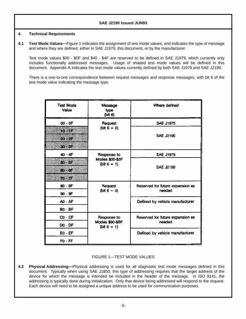
4.1 Test Mode Values—Figure 1 indicates the assignment of test mode values, and indicates the type of messageand where they are defined, either in SAE J1979, this document, or by the manufacturer.
Test mode values $00 - $0F and $40 - $4F are reserved to be defined in SAE J1979, which currently onlyincludes functionally addressed messages. Usage of shaded test mode values will be defined in thisdocument. Appendix A indicates the test mode values currently defined by both SAE J1979 and SAE J2190.
There is a one-to-one correspondence between request messages and response messages, with bit 6 of thetest mode value indicating the message type.
FIGURE 1—TEST MODE VALUES
4.2 Physical Addressing—Physical addressing is used for all diagnostic test mode messages defined in thisdocument. Typically when using SAE J1850, this type of addressing requires that the target address of thedevice for which the message is intended be included in the header of the message. In ISO 9141, theaddressing is typically done during initialization. Only that device being addressed will respond to the request.Each device will need to be assigned a unique address to be used for communication purposes.

SAE J2190 Issued JUN93
-6-
4.3 Miscellaneous Requirements
4.3.1 MESSAGE RESPONSE TIME—The vehicle controllers should respond to a diagnostic request within 100 ms of arequest. If there is no response within this time period, the tool can assume no response will be received.
4.3.2 AUTOMATIC RETURN TO NORMAL OPERATION—During a diagnostic procedure, the on-board controllers willoften be put into an abnormal mode of operation to aid in diagnostics. Examples are to report diagnosticdata periodically, to disable normal message transmission, or substitute an input or output parameter. Inpractice, the test procedure should return all on-board controllers to a normal mode of operation at the end ofthe procedure.
If a test device is disconnected from the vehicle before the on-board controllers have returned to normaloperation, the controllers should automatically detect that the tool is disconnected and return to a normalmode of operation. This should be accomplished by the on-board controller looking for a diagnosticmessage from the test device, which should be apparent from the message header. If a diagnostic messageis not received for a 5 s period of time, the on-board controller should automatically return to normaloperation.
Some diagnostic procedures may require more than 5 s without a required diagnostic message. For thesecases, this document specifies a "test tool present" message to be transmitted by the test device at leastonce every 5 s if there is no other message. On-board controllers should consider this as a diagnosticmessage and continue in the current mode of operation.
On-board controllers should also return to normal operation at power up or after a controller reset.
4.3.3 DIAGNOSTIC MESSAGE LENGTH—This document only defines the data bytes to be used in a diagnosticmessage. The actual number of data bytes in a message, referred to as "n" in the message data bytedescriptions in this document, depends on the requirements of the test mode and the maximum number ofbytes available in a diagnostic message. The maximum number of bytes available depends on the maximumallowable message length and the number of bytes used as a message header, error detection byte(s), or forother protocol specific purposes.
For example, the SAE J1850 data link effectively limits the total number of bytes in a message to 12. If themessage strategy includes a 3 byte header, 1 byte CRC, and 1 byte in-message response, then 7 data bytesare available for SAE J2190 functionality. If the message strategy includes a 3 byte header and 1 byte CRC,then 8 data bytes are available.
If other data links are used as the diagnostic data link, such as ISO 9141, there may be other messagelength limitations and, therefore, different limits on the number of data bytes available for SAE J2190functionality.
4.3.4 MESSAGE RESPONSE—All diagnostic request messages, except "Test Device Present (Mode $3F)," shouldreceive a response from the target module. A response is optional for the "Test Device Present" message.There are two types of response messages, specific and general. Specific response messages are uniquelypaired with each request message, and repeat enough data bytes of the request message to identity thespecific request. The "General Response Message (Mode $7F)" has a single test mode value. Theresponse message to be used for a request depends on the type of the request and whether or not themodule can perform the request.
When the request is for data and the module can perform the request (positive response), only the specificform of the response can be used. The response will either be a single message, multiple messages withadditional data, or periodic multiple messages with updated data values.

SAE J2190 Issued JUN93
-7-
If the request is for action, such as a request for entering a mode of operation or command to perform afunction, and the module can perform the request (positive response), either the specific response messageor general response message can be used. Those requests for which either response type is a validresponse have both response types indicated in this document.
If the request for either data or action cannot be performed by the module (negative response), only thegeneral response message can be used.
Figure 2 summarizes the valid response types for different types of requests.
FIGURE 2—VALID RESPONSE TYPES
With the General Response Message a response code is returned. Response codes can indicate a negativeor positive response. Standard response codes are included in the section with the definition of the GeneralResponse Message.
5. Test Modes
5.1 Modes $00 through $0F—Physically Addressed SAE J1979 Messages—Modes $00 through $0F arereserved to be defined in SAE J1979. The data byte content of the response to an SAE J1979 request whenthe device is addressed physically should be identical to the data byte content of the response when the deviceis addressed functionally. The only device that will respond to this request is the device to which the request isdirected.
The response to one of these requests will be a Mode $40 through $4F message.
The same PID list as specified in SAE J1979 will apply when the device is physically addressed using thesame test mode value. Although SAE J1979 reserves 256 PID values to be defined in that document, SAEJ1979 specifies that PID values $21 to $3F are reserved to be defined in this document. Possible values whichmay be considered to be included are:
Number of header bytes and formatUse of CRC versus checksum for error detectionUse of in-message responseMaximum number of data bytes allowed (based on header and in-message response)Use of manufacturer specific pins in the SAE J1962 connector

SAE J2190 Issued JUN93
-8-
5.2 Mode $10—Initiate Diagnostic Operation
5.2.1 FUNCTIONAL DESCRIPTION—The purpose of this mode is to inform devices on the serial data link that adiagnostic tool is ready to start diagnostic procedures using the data link. The on-board devices may need toalter their normal operation in order for the diagnostic procedures to be effective. One example is that thesystem may need to reduce the amount of data being sent on the data link to make more time available forthe diagnostic messages. Another possibility is that the system may need to degrade its normal operation inorder to be able to process the diagnostic requests. Systems that rely on data from modules beingdiagnosed may not receive data from those modules as frequently as normal. Use of this mode could informthe receiving modules that diagnostic procedures are in progress and they should not set diagnostic troublecodes based on not receiving data at the normal frequency.
An optional "level of diagnostics" byte may be used to indicate how much the normal operation must bealtered in order to accommodate the extra diagnostic procedures. These levels and their correspondingamount of change must be predefined in the module by the module manufacturer. The level of diagnosticscan be changed by sending a subsequent Mode $10 command.
5.2.2 MESSAGE DATA BYTES—(See Figure 3.)
FIGURE 3—MESSAGE DATA BYTES FOR MODE $10
5.3 Mode $11—Request Module Reset
5.3.1 FUNCTIONAL DESCRIPTION—This mode requests the module to effectively perform a module power on reset.The response message may be sent either before or after the module is reset. The response message mayalso be sent by modules whenever they perform a power on reset, whether requested by this test mode ornot.

SAE J2190 Issued JUN93
-9-
An optional data byte may be included in the request to indicate different levels of reset. Examples are:
First time ever connected to vehicleFirst time after battery disconnectAfter a full normal power down / power up cycleAfter minor power supply interruption
5.3.2 MESSAGE DATA BYTES—(See Figure 4.)
FIGURE 4—MESSAGE DATA BYTES FOR MODE $11
5.4 Mode $12—Request Diagnostic Freeze Frame Data
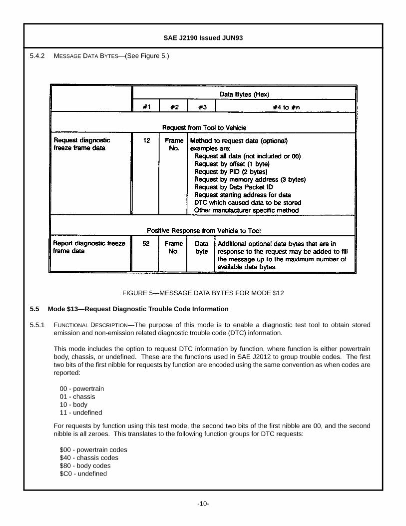
5.4.1 FUNCTIONAL DESCRIPTION—The purpose of this mode is to allow access to data values which were storedduring freeze frame conditions specified by the vehicle manufacturer. Data content, data format, and methodof retrieval are specified by the vehicle manufacturer. Typical uses for this mode are to report data storedupon detection of a system malfunction. Multiple frames of data may be stored before and/or after themalfunction is detected. The request for information includes a frame number followed by an optionalindication of the data requested.
If the optional data byte is not used, or is $00, then all data for the requested freeze frame will be reported. Ifthe optional byte is used, then the vehicle manufacturer will define the different methods used to specifywhich data is requested.
The on-board module will respond to this message by transmitting the requested data.
SAE J2190 Issued JUN93
-10-
5.4.2 MESSAGE DATA BYTES—(See Figure 5.)
FIGURE 5—MESSAGE DATA BYTES FOR MODE $12
5.5 Mode $13—Request Diagnostic Trouble Code Information
5.5.1 FUNCTIONAL DESCRIPTION—The purpose of this mode is to enable a diagnostic test tool to obtain storedemission and non-emission related diagnostic trouble code (DTC) information.
This mode includes the option to request DTC information by function, where function is either powertrainbody, chassis, or undefined. These are the functions used in SAE J2012 to group trouble codes. The firsttwo bits of the first nibble for requests by function are encoded using the same convention as when codes arereported:
00 - powertrain01 - chassis10 - body11 - undefined
For requests by function using this test mode, the second two bits of the first nibble are 00, and the secondnibble is all zeroes. This translates to the following function groups for DTC requests:
$00 - powertrain codes$40 - chassis codes$80 - body codes$C0 - undefined
SAE J2190 Issued JUN93
-11-
In addition, this document defines $FF as the function group to request DTC information for all functions.
This test mode can be used to either request diagnostic trouble codes, or request the number of diagnostictrouble codes. There are two ways this mode can request DTCs.
All codes can be requested by including only the test mode value in the request.Codes can be requested by function group (Powertrain, Chassis, Body, Undefined, or All) by sending the
function group followed by $00 as data bytes 2 and 3 ($00 00, $40 00, $80 00, $C0 00, or $FF 00).Requesting codes for all function groups by including $FF 00 yields the same response as notincluding function group in the request, but may be desired by a manufacturer for consistency withother messages.
There are also two ways this mode can request the number of DTCs.
Number of codes can be requested by including the function group as data byte 2, and not including databyte 3 ($FF as data byte 2 must be supported as a minimum to request the total number of DTC).
Number of codes can be requested by function group (Powertrain, Chassis, Body, Undefined, or All) bysending the function group followed by $FF as data bytes 2 and 3 ($00 FF, $40 FF, $80 FF, $C0 FF, or$FF FF). Requesting number of codes for all function groups by including $FF FF yields the sameresponse as including only $FF as data byte 2 in the request, but may be desired by a manufacturer forconsistency with other messages.
The response to a Mode $13 request for DTC will be one or more Mode $53 messages. If no codes are storedin the module, then the module will respond with one of the following:
Mode $53 with no additional data bytesMode $53 padded with $00 00 to fill response
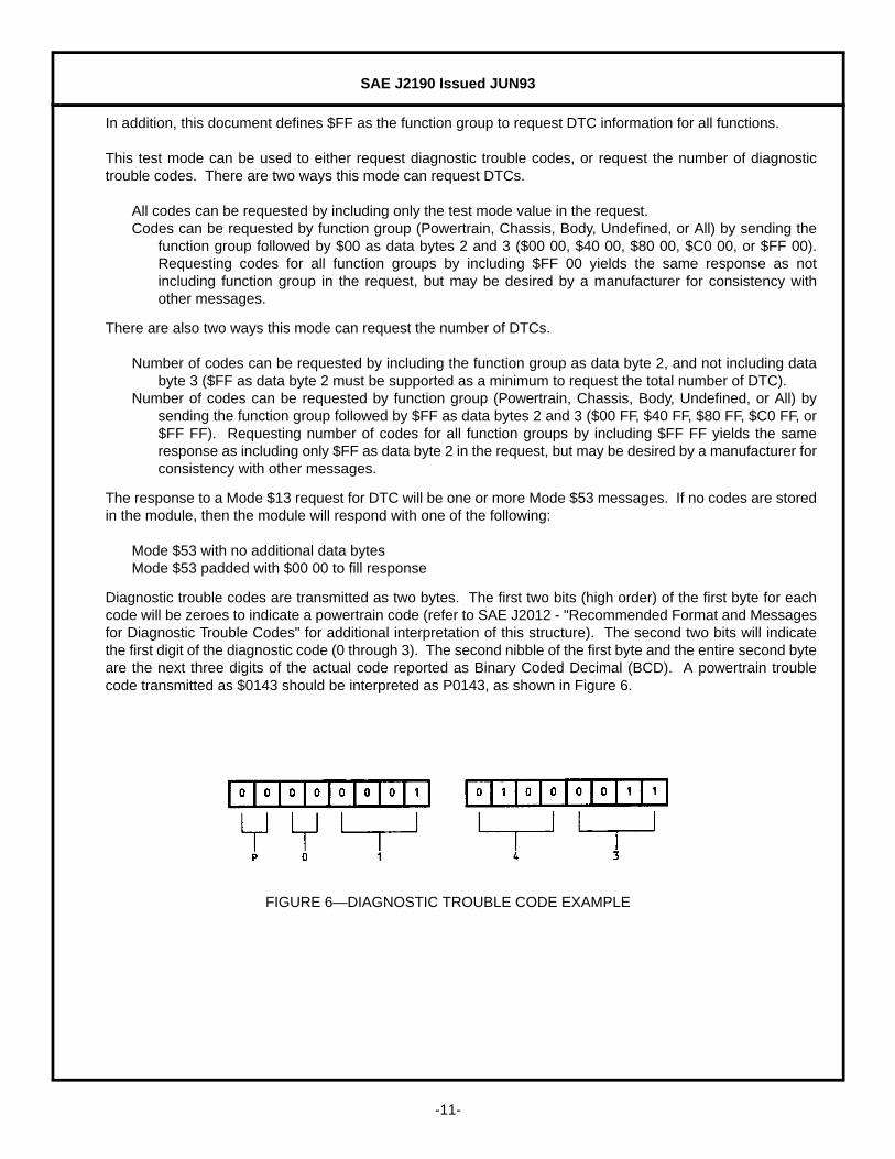
Diagnostic trouble codes are transmitted as two bytes. The first two bits (high order) of the first byte for eachcode will be zeroes to indicate a powertrain code (refer to SAE J2012 - "Recommended Format and Messagesfor Diagnostic Trouble Codes" for additional interpretation of this structure). The second two bits will indicatethe first digit of the diagnostic code (0 through 3). The second nibble of the first byte and the entire second byteare the next three digits of the actual code reported as Binary Coded Decimal (BCD). A powertrain troublecode transmitted as $0143 should be interpreted as P0143, as shown in Figure 6.
FIGURE 6—DIAGNOSTIC TROUBLE CODE EXAMPLE

SAE J2190 Issued JUN93
-12-
5.5.2 MESSAGE DATA BYTES—(See Figure 7.)
FIGURE 7—MESSAGE DATA BYTES FOR MODE $13

SAE J2190 Issued JUN93
-13-
5.6 Mode $14—Clear Diagnostic Information
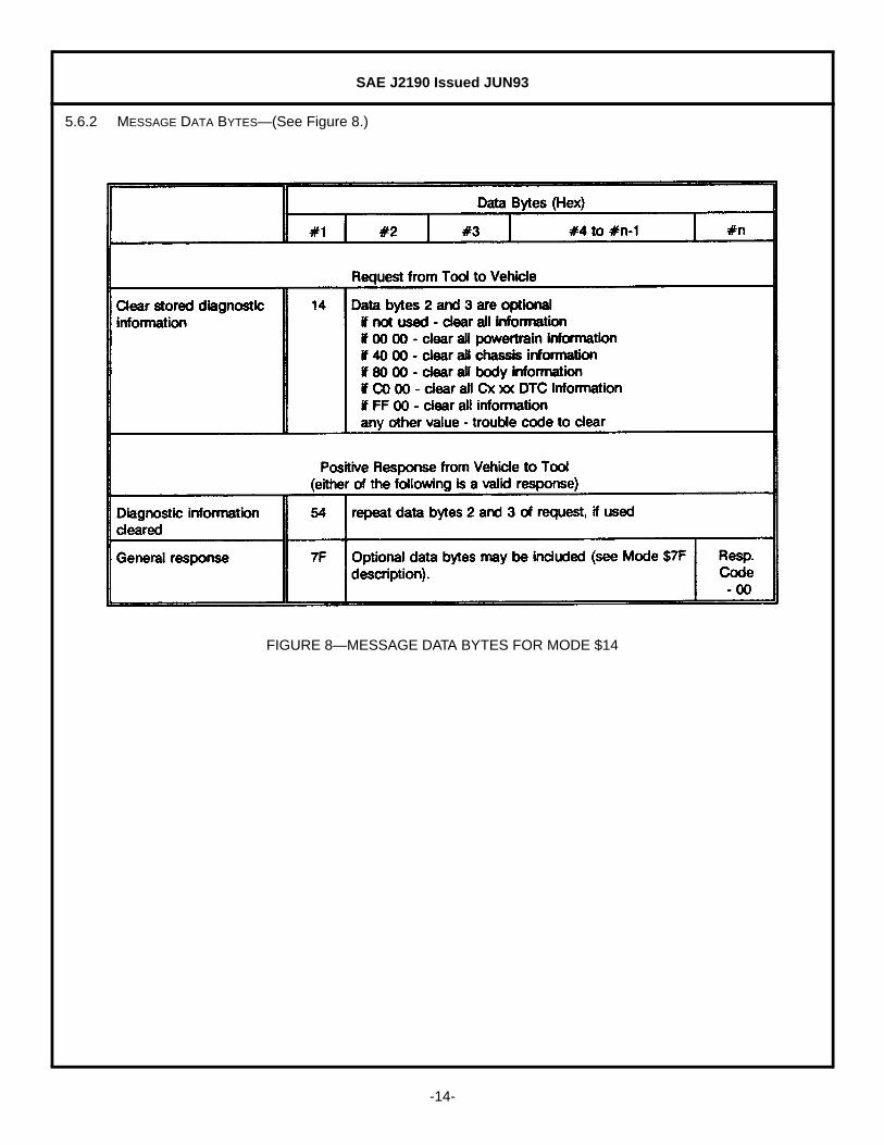
5.6.1 FUNCTIONAL DESCRIPTION—The purpose of this mode is to provide a means for the external test device tocommand on-board modules to clear all diagnostic information. This information includes primarilydiagnostic trouble codes, but can also include freeze frame data or other on-board test results that may bestored as a result of the trouble code being set. This extra information is device dependent.
There are three ways this mode can be used. If only the test mode value is included in the request, then alldiagnostic information stored in the module is to be cleared.
Diagnostic information can optionally be cleared by function (Powertrain, Chassis, or Body) by sendingP0000, C0000, or B0000 as data bytes 2 and 3. These must be encoded using the same convention aswhen codes are reported (see description for Mode $13). The first two bits of the first nibble are:
00 - powertrain01 - chassis10 - body11 - undefined
This translates to the following values for data bytes #2 and #3:
$00 00 - powertrain codes$40 00 - chassis codes$80 00 - body codes$C0 00 - undefined
Diagnostic information can also optionally be cleared for a single trouble code by including the trouble codeto clear as optional bytes in the request. The information stored with an individual trouble code would needto be clearly identified within the module and cleared at the same time.
Caution when clearing by single trouble code: This capability should not be provided and used unlessconsideration is given to the possible consequences of this option. If a single fault caused multiple troublecodes to be set, and a service technician found a defective component, repaired it, and cleared a singletrouble code associated with that fault, then the device would still contain trouble codes that were set basedon that fault. The next technician to check codes would read those codes, and if he did not know the vehiclehistory, he may try to repair the vehicle based only on the remaining trouble codes, which could waste timeand result in replacement of good components.
Allowing use of this feature to clear emission related trouble codes should be considered very carefully toguard against improper diagnosis. Difficult interpretation can result if the system allowed clearing a singleemission related trouble code. CARB required information could report that trouble codes are stored, butthey would not be reported when an SAE J1979 Mode $04 message is sent to request those codes. Freezeframe data could be stored for a given trouble code, but that code would not be reported as stored.
SAE J2190 Issued JUN93
-14-
5.6.2 MESSAGE DATA BYTES—(See Figure 8.)
FIGURE 8—MESSAGE DATA BYTES FOR MODE $14

SAE J2190 Issued JUN93
-15-
5.7 Mode $17—Request Status of Diagnostic Trouble Codes
5.7.1 FUNCTIONAL DESCRIPTION—The purpose of this mode is to provide a means to determine the status ofdiagnostic trouble codes.
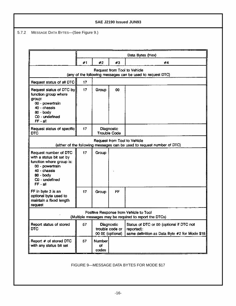
This mode is nearly identical in operation to Mode $13, except that only a single DTC, followed by the statusof that DTC, is reported in a single response. This mode also allows a request for the status of a single DTC.The discussion of function groups and the method of reporting DTCs is identical to the description in Mode$13.
This test mode can be used to either request status of diagnostic trouble codes, or request the number ofdiagnostic trouble codes with a status bit set. There are three ways this mode can request DTCs.
All codes can be requested by only including the test mode value in the request.Codes can be requested by function group (Powertrain, Chassis, Body, Undefined, or All) by sending the
function group followed by $00 as data bytes 2 and 3 ($00 00, $40 00, $80 00, $C0 00, or $FF 00).Requesting codes for all function groups by including $FF 00 yields the same response as notincluding function group in the request, but may be desired by a manufacturer for consistency withother messages.
Status of a single trouble code can be requested by including the trouble code as data bytes 2 and 3 in therequest.
There are two ways this mode can request the number of DTCs with a status bit set.
Number of codes can be requested by including the function group as data byte 2, and not including databyte 3 ($FF as data byte 2 must be supported as a minimum to request the total number of DTC).
Number of codes can be requested by function group (Powertrain, Chassis, Body, Undefined, or All) bysending the function group fy $FF as data bytes 2 and 3 ($00 FF, $40 FF, $80 FF, $Co FF, or $FF FF).Requesting number of codes for all function groups by including $FF FF yields the same response asincluding only $FF as data byte 2 in the request, but may be desired by a manufacturer for consistencywith other messages.
Multiple Mode $57 response messages may be reported due to a single Mode $17 request message,depending on the type of request and the number of diagnostic trouble codes stored in the module. Eachresponse message will report the status of a single DTC. If no codes are stored in the module, then themodule will respond with one of the following:
Mode $57 with no additional data bytesMode $57 with $00 00 for DTC and $00 for status
SAE J2190 Issued JUN93
-16-
5.7.2 MESSAGE DATA BYTES—(See Figure 9.)
FIGURE 9—MESSAGE DATA BYTES FOR MODE $17
SAE J2190 Issued JUN93
-17-
5.8 Mode $18—Request Diagnostic Trouble Codes by Status
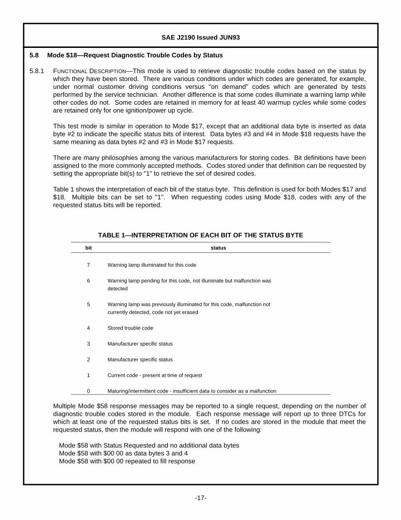
5.8.1 FUNCTIONAL DESCRIPTION—This mode is used to retrieve diagnostic trouble codes based on the status bywhich they have been stored. There are various conditions under which codes are generated, for example,under normal customer driving conditions versus "on demand" codes which are generated by testsperformed by the service technician. Another difference is that some codes illuminate a warning lamp whileother codes do not. Some codes are retained in memory for at least 40 warmup cycles while some codesare retained only for one ignition/power up cycle.
This test mode is similar in operation to Mode $17, except that an additional data byte is inserted as databyte #2 to indicate the specific status bits of interest. Data bytes #3 and #4 in Mode $18 requests have thesame meaning as data bytes #2 and #3 in Mode $17 requests.
There are many philosophies among the various manufacturers for storing codes. Bit definitions have beenassigned to the more commonly accepted methods. Codes stored under that definition can be requested bysetting the appropriate bit(s) to "1" to retrieve the set of desired codes.
Table 1 shows the interpretation of each bit of the status byte. This definition is used for both Modes $17 and$18. Multiple bits can be set to "1". When requesting codes using Mode $18, codes with any of therequested status bits will be reported.
Multiple Mode $58 response messages may be reported to a single request, depending on the number ofdiagnostic trouble codes stored in the module. Each response message will report up to three DTCs forwhich at least one of the requested status bits is set. If no codes are stored in the module that meet therequested status, then the module will respond with one of the following:
Mode $58 with Status Requested and no additional data bytesMode $58 with $00 00 as data bytes 3 and 4Mode $58 with $00 00 repeated to fill response
TABLE 1—INTERPRETATION OF EACH BIT OF THE STATUS BYTE
bit status
7 Warning lamp illuminated for this code
6 Warning lamp pending for this code, not illuminate but malfunction was
detected
5 Warning lamp was previously illuminated for this code, malfunction not
currently detected, code not yet erased
4 Stored trouble code
3 Manufacturer specific status
2 Manufacturer specific status
1 Current code - present at time of request
0 Maturing/intermittent code - insufficient data to consider as a malfunction

SAE J2190 Issued JUN93
-18-
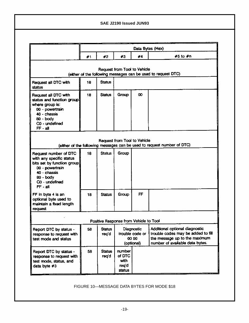
5.8.2 MESSAGE DATA BYTES—(See Figure 10.)
SAE J2190 Issued JUN93
-19-
FIGURE 10—MESSAGE DATA BYTES FOR MODE $18

SAE J2190 Issued JUN93
-20-
5.9 Mode $20—Return to Normal Operation
5.9.1 FUNCTIONAL DESCRIPTION—The on-board device will return to the normal mode of operation when thismessage is received. All normal algorithms and normal communications will be resumed. All activediagnostic modes will be terminated without sending additional request or response messages. If themodule had been unlocked using security access, then the module should also be locked.
5.9.2 MESSAGE DATA BYTES—(See Figure 11.)
FIGURE 11—MESSAGE DATA BYTES FOR MODE $20

SAE J2190 Issued JUN93
-21-
5.10 Modes $21 to $23—Request Diagnostic Data
5.10.1 FUNCTIONAL DESCRIPTION—The purpose of these modes is to request data values, such as analog inputsand outputs, digital inputs and outputs, freeze frame data, calculated values, bit mapped fault code data, andsystem status information. The request for information can be by one of three methods:
Mode $21 - Offset (1 byte)Mode $22 - Parameter Identification (PID) value (2 bytes)Mode $23 − Memory Address (3 bytes)
System designers have the flexibility to maintain a table including PID numbers and data values, withouthaving consecutive PID numbers. In this case, the tool can request either by PID number or offset. Arequest by offset is generally an easier method for the software to retrieve data because it does not need tosearch for the PID in the table. Mode $24 allows use of the PID number one time to get the offset, withsuccessive requests by offset for better system performance.
Figure 12 is an example of a table that could be included in the system module to utilize all of these modes.The offset is the row number of the table and is not a table entry. The location of the information within thistable can be calculated by multiplying the offset times the number of bytes in each row. The location inmemory can then be calculated by adding the location within the table to the base location of the table inmemory.
FIGURE 12—OFFSET/PID/ADDRESS TABLE EXAMPLE
A Mode $21 request by offset would calculate the location of the offset information in the table, find theaddress and scaling for that value, and return the appropriate number of bytes of information starting at thataddress.
A Mode $22 request by PID would search through the table for the requested PID, find the address andscaling for that value, and return the appropriate number of bytes of information starting at that address.
A Mode $23 request by address would ignore this table and report data starting at the address specified inthe request.

SAE J2190 Issued JUN93
-22-
5.10.2 MODE $21 MESSAGE DATA BYTES—(See Figure 13.)
FIGURE 13—MESSAGE DATA BYTES FOR MODE $21

SAE J2190 Issued JUN93
-23-
5.10.3 MODE $22 MESSAGE DATA BYTES—(See Figure 14.)
FIGURE 14—MESSAGE DATA BYTES FOR MODE $22

SAE J2190 Issued JUN93
-24-
5.10.4 MODE $23 MESSAGE DATA BYTES—(See Figure 15.)
FIGURE 15—MESSAGE DATA BYTES FOR MODE $23

SAE J2190 Issued JUN93
-25-
5.11 Mode $24—Request Scaling and Offset / PID
5.11.1 FUNCTIONAL DESCRIPTION—The purpose of Mode $24 is to request either scaling and PID information byspecifying offset, or request scaling and offset information by specifying PID. $FF should be included in therequest for the data byte value not being specified. If both offset and Parameter ID are specified, and theparameter ID is not correct for the offset specified, unexpected data values can be returned. Operation ofthis mode is similar to either Mode $21 or $22, depending on which value was specified in the request. Theresponse would include offset, PID, and scaling for the requested entry. Any data byte values not supportedby the module would report $FF.
Mode $24 can also be used to determine the PID table by incrementing the offset in repeated Mode $24requests.
5.11.2 MESSAGE DATA BYTES—(See Figure 16.)
FIGURE 16—MESSAGE DATA BYTES FOR MODE $24
SAE J2190 Issued JUN93
-26-
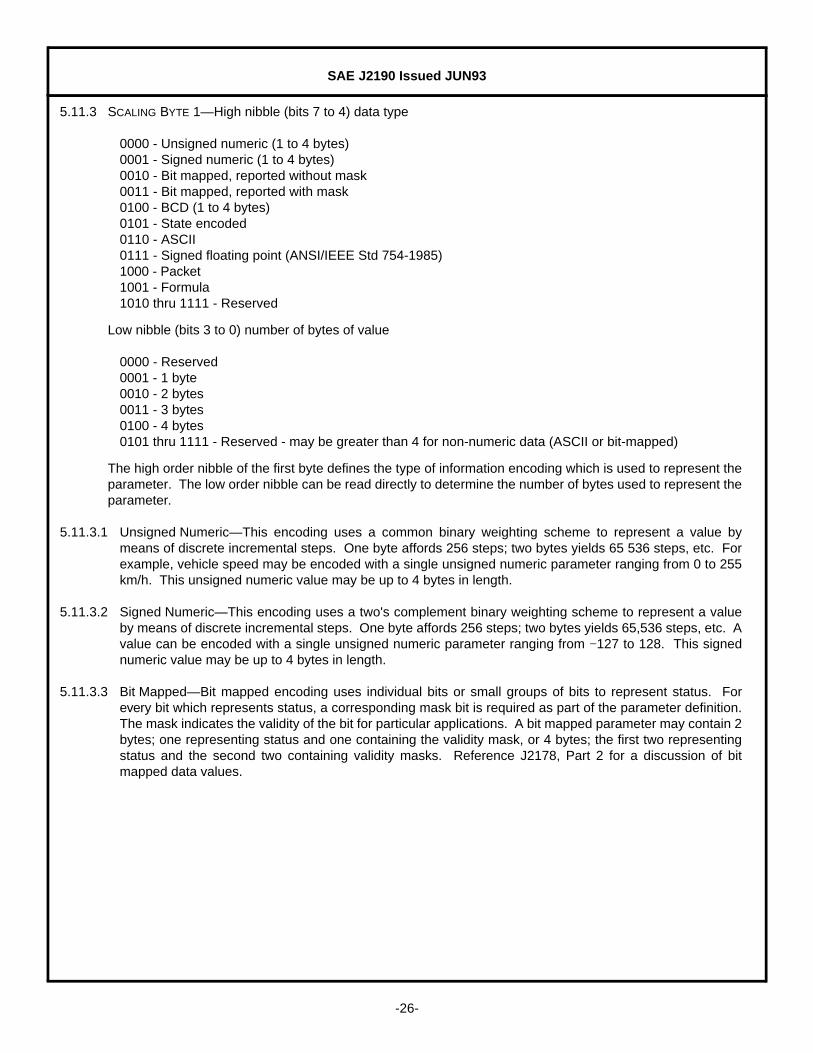
5.11.3 SCALING BYTE 1—High nibble (bits 7 to 4) data type
0000 - Unsigned numeric (1 to 4 bytes)0001 - Signed numeric (1 to 4 bytes)0010 - Bit mapped, reported without mask0011 - Bit mapped, reported with mask0100 - BCD (1 to 4 bytes)0101 - State encoded0110 - ASCII0111 - Signed floating point (ANSI/IEEE Std 754-1985)1000 - Packet1001 - Formula1010 thru 1111 - Reserved
Low nibble (bits 3 to 0) number of bytes of value
0000 - Reserved0001 - 1 byte0010 - 2 bytes0011 - 3 bytes0100 - 4 bytes0101 thru 1111 - Reserved - may be greater than 4 for non-numeric data (ASCII or bit-mapped)
The high order nibble of the first byte defines the type of information encoding which is used to represent theparameter. The low order nibble can be read directly to determine the number of bytes used to represent theparameter.
5.11.3.1 Unsigned Numeric—This encoding uses a common binary weighting scheme to represent a value bymeans of discrete incremental steps. One byte affords 256 steps; two bytes yields 65 536 steps, etc. Forexample, vehicle speed may be encoded with a single unsigned numeric parameter ranging from 0 to 255km/h. This unsigned numeric value may be up to 4 bytes in length.
5.11.3.2 Signed Numeric—This encoding uses a two's complement binary weighting scheme to represent a valueby means of discrete incremental steps. One byte affords 256 steps; two bytes yields 65,536 steps, etc. Avalue can be encoded with a single unsigned numeric parameter ranging from −127 to 128. This signednumeric value may be up to 4 bytes in length.
5.11.3.3 Bit Mapped—Bit mapped encoding uses individual bits or small groups of bits to represent status. Forevery bit which represents status, a corresponding mask bit is required as part of the parameter definition.The mask indicates the validity of the bit for particular applications. A bit mapped parameter may contain 2bytes; one representing status and one containing the validity mask, or 4 bytes; the first two representingstatus and the second two containing validity masks. Reference J2178, Part 2 for a discussion of bitmapped data values.
SAE J2190 Issued JUN93
-27-
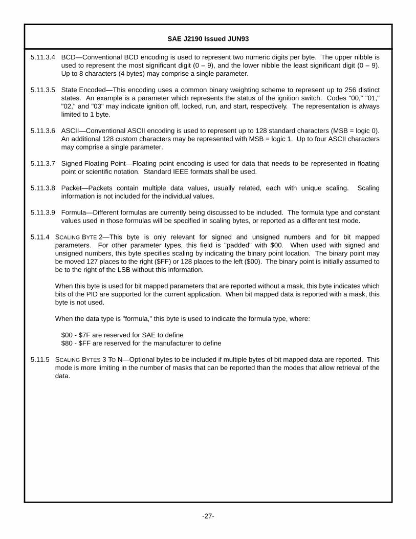
5.11.3.4 BCD—Conventional BCD encoding is used to represent two numeric digits per byte. The upper nibble isused to represent the most significant digit (0 – 9), and the lower nibble the least significant digit (0 – 9).Up to 8 characters (4 bytes) may comprise a single parameter.
5.11.3.5 State Encoded—This encoding uses a common binary weighting scheme to represent up to 256 distinctstates. An example is a parameter which represents the status of the ignition switch. Codes "00," "01,""02," and "03" may indicate ignition off, locked, run, and start, respectively. The representation is alwayslimited to 1 byte.
5.11.3.6 ASCII—Conventional ASCII encoding is used to represent up to 128 standard characters (MSB = logic 0).An additional 128 custom characters may be represented with MSB = logic 1. Up to four ASCII charactersmay comprise a single parameter.
5.11.3.7 Signed Floating Point—Floating point encoding is used for data that needs to be represented in floatingpoint or scientific notation. Standard IEEE formats shall be used.
5.11.3.8 Packet—Packets contain multiple data values, usually related, each with unique scaling. Scalinginformation is not included for the individual values.
5.11.3.9 Formula—Different formulas are currently being discussed to be included. The formula type and constantvalues used in those formulas will be specified in scaling bytes, or reported as a different test mode.
5.11.4 SCALING BYTE 2—This byte is only relevant for signed and unsigned numbers and for bit mappedparameters. For other parameter types, this field is "padded" with $00. When used with signed andunsigned numbers, this byte specifies scaling by indicating the binary point location. The binary point maybe moved 127 places to the right ($FF) or 128 places to the left ($00). The binary point is initially assumed tobe to the right of the LSB without this information.
When this byte is used for bit mapped parameters that are reported without a mask, this byte indicates whichbits of the PID are supported for the current application. When bit mapped data is reported with a mask, thisbyte is not used.
When the data type is "formula," this byte is used to indicate the formula type, where:
$00 - $7F are reserved for SAE to define$80 - $FF are reserved for the manufacturer to define
5.11.5 SCALING BYTES 3 TO N—Optional bytes to be included if multiple bytes of bit mapped data are reported. Thismode is more limiting in the number of masks that can be reported than the modes that allow retrieval of thedata.

SAE J2190 Issued JUN93
-28-
5.12 Mode $25—Stop Transmitting Requested Data
5.12.1 FUNCTIONAL DESCRIPTION—The purpose of Mode $25 is to stop all data transmission that was started by anytest mode that can request repetitive data. If only an individual data request is to be stopped, then that valuecan be stopped by sending a request message for the mode that requested the data with a "0" for the datarate. In practice, if a message is already in an outgoing message queue ready to be sent, this wouldprobably not remove that message from the queue, but it would prevent additional messages from beingadded to the queue. Response is either Mode $65 or general response.
5.12.2 MESSAGE DATA BYTES—(See Figure 17.)
FIGURE 17—MESSAGE DATA BYTES FOR MODE $25

SAE J2190 Issued JUN93
-29-
5.13 Mode $26—Specify Data Rates
5.13.1 FUNCTIONAL DESCRIPTION—The purpose of Mode $26 is to specify the setting of data rates for data to betransmitted by request messages that can request repetitive data. Those modes include "Data Rate" as adata byte in the request message. Modules will normally have default rates associated with slow, mid, andfast. The slow rate should be about one or two samples per second, the mid rate should be normal handheldscan tool rates of about four to ten samples per second, and the fast rate 20 or more samples per second.Default rates are defined within each module and should be based on the frequency of change typical for thevalue reported, uses for that data, and the capability of the processor.
5.13.2 MESSAGE DATA BYTES—(See Figure 18.)
FIGURE 18—MESSAGE DATA BYTES FOR MODE $26

SAE J2190 Issued JUN93
-30-
5.14 Mode $27—Security Access Mode
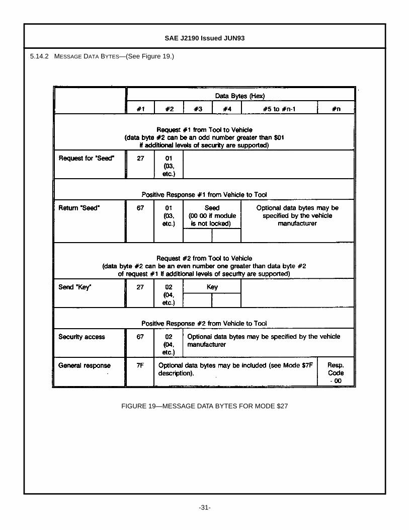
5.14.1 FUNCTIONAL DESCRIPTION—The primary purpose of this mode is to restrict unauthorized intrusion into the on-board controller. Improper programs could potentially damage the electronics or other vehicle componentsor risk the vehicle's compliance to emission or safety standards. This mode is intended to be used toimplement the data link security measures defined in SAE J2186.
The external device will request the controller to "Unlock" itself by sending Request #1. The controller willrespond by sending a "Seed" using Response #1. The external device will respond by returning a "Key"number back to the controller using Request #2. The controller would compare this "Key" to one internallystored. If the two numbers agree, then the controller will enable ("Unlock") the external device's access tospecific test modes and indicate that with Mode $67, Response #2. If upon two attempts of a Request #2where the two keys do not compare, then the controller will insert a 10 s time delay before allowing furtherattempts. This time delay will also be required before responding to a Mode $27 request #1 for eachcontroller power-on.
If a device supports security, but is already unlocked when a Request #1 is received, that device shouldrespond with a Response #1 message with a seed of $00 00. A test device could use this method todetermine if a device is locked by checking for a non-zero seed.
The security system will not prevent normal diagnostic or vehicle communications between external devicesand the on-board controller. Proper "Unlocking" of the controller is a prerequisite to the external device'sability to perform some of the more critical functions such as reading specific memory locations within thecontroller, downloading information to specific locations, or downloading routines for execution by thecontroller. In other words, the only access to the controller permitted while in a "locked" mode is through theproduct specific software. This permits the product specific software to protect itself from unauthorizedintrusion.
Devices that provide security should support reject messages if a secure mode is requested while the deviceis locked. The reject message to be returned is a general response message Mode $7F, with a responsecode $33 to indicate the product is secured.
Some devices could support multiple levels of security, either for different functions controlled by the device,or to allow different capabilities to be exercised. These additional levels of security can be accessed by usingrequests #3 and #4, etc. The second data byte of the request for seed should always be an odd number, andthe second data byte of the message to send the key should be the next even number.
SAE J2190 Issued JUN93
-31-
5.14.2 MESSAGE DATA BYTES—(See Figure 19.)
FIGURE 19—MESSAGE DATA BYTES FOR MODE $27

SAE J2190 Issued JUN93
-32-
5.15 Mode $28—Disable Normal Message Transmission
5.15.1 FUNCTIONAL DESCRIPTION—The purpose of this mode is to inhibit the on-board device from transmittingnormal operating data on the link, while still performing other functions normally. The device will continue tooperate in whatever diagnostic mode it was operating in prior to the Mode $28 command.
If an unsafe or undesirable vehicle operating condition would result from the lack of normal messages, thenthis mode could cause all nonessential messages to be inhibited. The optional manufacturer specific "level"data byte could be used to indicate which normal mode messages to disable. Defining which messages todisable is determined by the system designer to ensure safe vehicle operation. When using this test mode,some provision must be made to allow for other devices that rely on information from the silenced device sothat they do not set diagnostic trouble codes due to the lack of required information.
One use for this test mode is to reduce message traffic on the data link. This would make more timeavailable for diagnostic messages. Another use for this mode is to allow the test equipment to emulate theremote device for diagnostic purposes. In this scenario, the test device would send a Mode $28 request tothe device to be emulated. The test device would then respond to all normal communication requestmessages directed to that device, most likely with data intended to cause a known response by a system thatuses the information in the response. The test device can then observe the actions of those systems.
5.15.2 MESSAGE DATA BYTES—(See Figure 20.)
FIGURE 20—MESSAGE DATA BYTES FOR MODE $28

SAE J2190 Issued JUN93
-33-
5.16 Mode $29—Enable Normal Message Transmission
5.16.1 FUNCTIONAL DESCRIPTION—The purpose of this mode is to cause an on-board device to resume normalcommunications after previously disabling these messages by a Mode $28 command. The device willcontinue to operate in whatever diagnostic modes were set by previous messages, such as executing on-board routines.
5.16.2 MESSAGE DATA BYTES—(See Figure 21.)
FIGURE 21—MESSAGE DATA BYTES FOR MODE $29
5.17 Mode $2A—Request Diagnostic Data Packet(s)
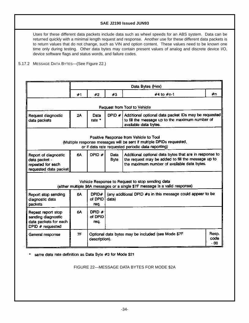
5.17.1 FUNCTIONAL DESCRIPTION—The purpose of this mode is to request diagnostic data packets that contain datavalues, such as analog inputs and outputs, digital inputs and outputs, freeze frame data, calculated values,bit mapped fault code data, and system status information. This Mode differs from Modes $21 through $23in that multiple data packets can be requested, each containing multiple data values. These data packetscan either be predefined in the on-board control module or dynamically defined using Mode $2B or $2C.
The on-board module will respond to this message by transmitting multiple response messages specific tothat device. The data packet ID Bytes in the request allow multiple Mode $2A data packets to be requested.Data packets should be defined which include data that is commonly used together, or changes together.
SAE J2190 Issued JUN93
-34-
Uses for these different data packets include data such as wheel speeds for an ABS system. Data can bereturned quickly with a minimal length request and response. Another use for these different data packets isto return values that do not change, such as VIN and option content. These values need to be known onetime only during testing. Other data bytes may contain present values of analog and discrete device I/O,device software flags and status words, and failure codes.
5.17.2 MESSAGE DATA BYTES—(See Figure 22.)
FIGURE 22—MESSAGE DATA BYTES FOR MODE $2A

SAE J2190 Issued JUN93
-35-
5.18 Mode $2B—Dynamically Define Data Packet by Single Byte Offsets
5.18.1 FUNCTIONAL DESCRIPTION—This test mode can be used to dynamically define data packets that cansubsequently be requested using a Mode $2A request. This mode is a special case alternative to usingmultiple Mode $2C messages, because a single request message can be used to completely define thecontents of a data packet. All other methods to specify the data values to be included in data packets usingMode $2C would also require multiple messages, therefore, special modes to build data packets by PID ormemory address are not included.
If the parameter for any offset value is longer than 1 byte, then offset data bytes in the request should befilled with $FF for each additional byte in the data value requested (see message example). This forces thedata value byte locations in the response message to mirror the offset value byte locations in the requestmessage.
5.18.2 MESSAGE DATA BYTES—(See Figure 23.)
FIGURE 23—MESSAGE DATA BYTES FOR MODE $2B

SAE J2190 Issued JUN93
-36-
5.18.3 MESSAGE EXAMPLE—Figure 24 is an example of messages required to define a data packet by offset andthen request that data packet. The data packet can be defined with a single message and requested withanother message.
FIGURE 24—DATA PACKET EXAMPLE
SAE J2190 Issued JUN93
-37-
5.19 Mode $2C—Dynamically Define Diagnostic Data Packet
5.19.1 FUNCTIONAL DESCRIPTION—This test mode can be used to dynamically define data packets that cansubsequently be requested using a Mode $2A request. This single test mode is an alternative to multiplemodes to define data packets by offset, PID, and memory address.
This mode allows data packets to be defined in different ways, and also allows a single data packet to includedata specified in different ways. Multiple messages must be sent to define a single data packet. Eachmessage constructs a portion of the data packet, and includes an indication of how the data is beingrequested, the starting byte of the data packet, and the number of bytes to be specified for the data packet.
Data packets can be shortened by sending a data packet definition with the starting byte indicating the firstdata byte not to be included, and 0 as the length. This should be interpreted as 0 bytes at the startinglocation, which means that data byte is not in the response message.
Data packet definitions can be cleared by sending a message with 1 as the starting data byte and 0 as thenumber of bytes. Requesting this data packet would result in a response which would include the modevalue, data packet ID, and no data.
Data packet definitions can be removed by sending a message with 0 as the starting data byte and 0 as thenumber of bytes. This would free memory space, if needed.
An optional feature of this mode is to request the present definition for the data packet. This is accomplishedby sending a Mode $2B with the data packet ID as the only additional data byte. The result is multiple $6Bresponses, each including data bytes that resemble the $2B messages that created the data packet.

SAE J2190 Issued JUN93
-38-
5.19.2 MESSAGE DATA BYTES—(See Figure 25.)
FIGURE 25—MESSAGE DATA BYTES FOR MODE $2C

SAE J2190 Issued JUN93
-39-
5.19.3 MESSAGE EXAMPLE—Figure 26 shows the messages required to define a data packet and then request thatdata packet. Data packet #26 is to be defined as:
Value for PID $01 04 (1 byte data value)Value at offset $32 (2 byte data value)2 bytes of data at memory address $24 81 70
This definition requires three sets of request / report messages, and the data packet request requires one setof messages.
FIGURE 26A—DATA PACKET DEFINITION EXAMPLE

SAE J2190 Issued JUN93
-40-
FIGURE 26B—DATA PACKET DEFINITION EXAMPLE (CONTINUED)

SAE J2190 Issued JUN93
-41-
5.20 Mode $2F—Input/Output Control by PID
5.20.1 FUNCTIONAL DESCRIPTION—This capability allows the tester to verify proper operation of external input andoutput components and circuitry by isolation techniques. Real world sensor inputs can be temporarilybypassed, and direct control of output devices can be achieved. Since substitution may cause the controlmodule to operate in a manner which is unsuitable or unsafe for "on-the-road" operation, precautions mustbe taken to ensure safe operation. The substituted value is used only for the duration of the diagnosticprocedure, and when the module is returned to normal operation, or control of the data value is returned tothe vehicle, then the substituted value reverts back to the normal value determined by the control system.
Parameter IDs (PIDs) are assigned by the manufacturer for those input, output, and intermediate (calculated)values that are allowed to be substituted. The PID assignments can be the same PID values that are usedwith a Mode $22 request for data by PID.
5.20.2 MESSAGE DATA BYTES—(See Figure 27.)
FIGURE 27—MESSAGE DATA BYTES FOR MODE $2F
SAE J2190 Issued JUN93
-42-
5.21 Mode $30—input/output Control By Data Value Id
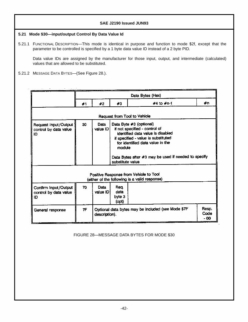
5.21.1 FUNCTIONAL DESCRIPTION—This mode is identical in purpose and function to mode $2f, except that theparameter to be controlled is specified by a 1 byte data value ID instead of a 2 byte PID.
Data value IDs are assigned by the manufacturer for those input, output, and intermediate (calculated)values that are allowed to be substituted.
5.21.2 MESSAGE DATA BYTES—(See Figure 28.).
FIGURE 28—MESSAGE DATA BYTES FOR MODE $30

SAE J2190 Issued JUN93
-43-
5.22 Modes $31 to $33—Perform Diagnostic Routine by Test Number
5.22.1 FUNCTIONAL DESCRIPTION—The purpose of these modes is to execute diagnostic tests and obtain testresults. The diagnostic routines are manufacturer defined and executed in the control module by referencingthe test number. Each module may support up to 255 distinct diagnostic routines. Definition of the routinesis defined by the module manufacturer.
Reported results may consist of any set of return information, such as measured test values or fault codes.
Three sets of messages are used to perform tests resident in an on-board control module. These messagesperform three functions:
Mode $31 - Enter/start Diagnostic Routine by Test NumberMode $32 - Exit/stop Diagnostic Routine by Test NumberMode $33 - Request Diagnostic Routine Results by Test Number
The tests are known by the module and identified by a test number. They are usually permanently stored inthe module, but may have been downloaded by Modes $34 and $36.
These test numbers could either be tests that run instead of normal operating code, or could be routines thatare enabled in this mode and execute with the normal operating code. In the first case, normal systemoperation for the controller being tested is not possible. In the second case, multiple diagnostic routines canbe enabled that run while all other parts of the system are functioning normally.
Any combination of the messages can be used, depending on the implementation in the module. Someexamples are:
Tester sends a Mode $31 message to start a test. The module reports that the test has started with aMode $71 and runs the test until a Mode $32 is sent to stop the test. The module exits the test andinforms the tester with a Mode $72 that the test has stopped. The tester then requests test results witha Mode $33, and the module reports the results with a Mode $73 message.
Tester sends a Mode $31 message to start a test. The Module confirms the test has started, exits whenthe test is done and reports results using Mode $73.
Tester sends a Mode $31 message to start a test. The Module starts the test and periodically reportsresults using Mode $73 until a Mode $32 is sent to stop the test.
The on-board controller starts a test automatically, stops the test automatically and reports results using aMode $73 message automatically. This requires no request messages from the tester.
These examples demonstrate both maximum and minimum use of the available message. Test equipmentneeds to know what tests are available, which messages are required, and how to interpret the results.
The general purpose response, Mode $7F, may also be used instead of a Mode $71 or Mode $72 messageto acknowledge entry or exit from a diagnostic routine.
SAE J2190 Issued JUN93
-44-
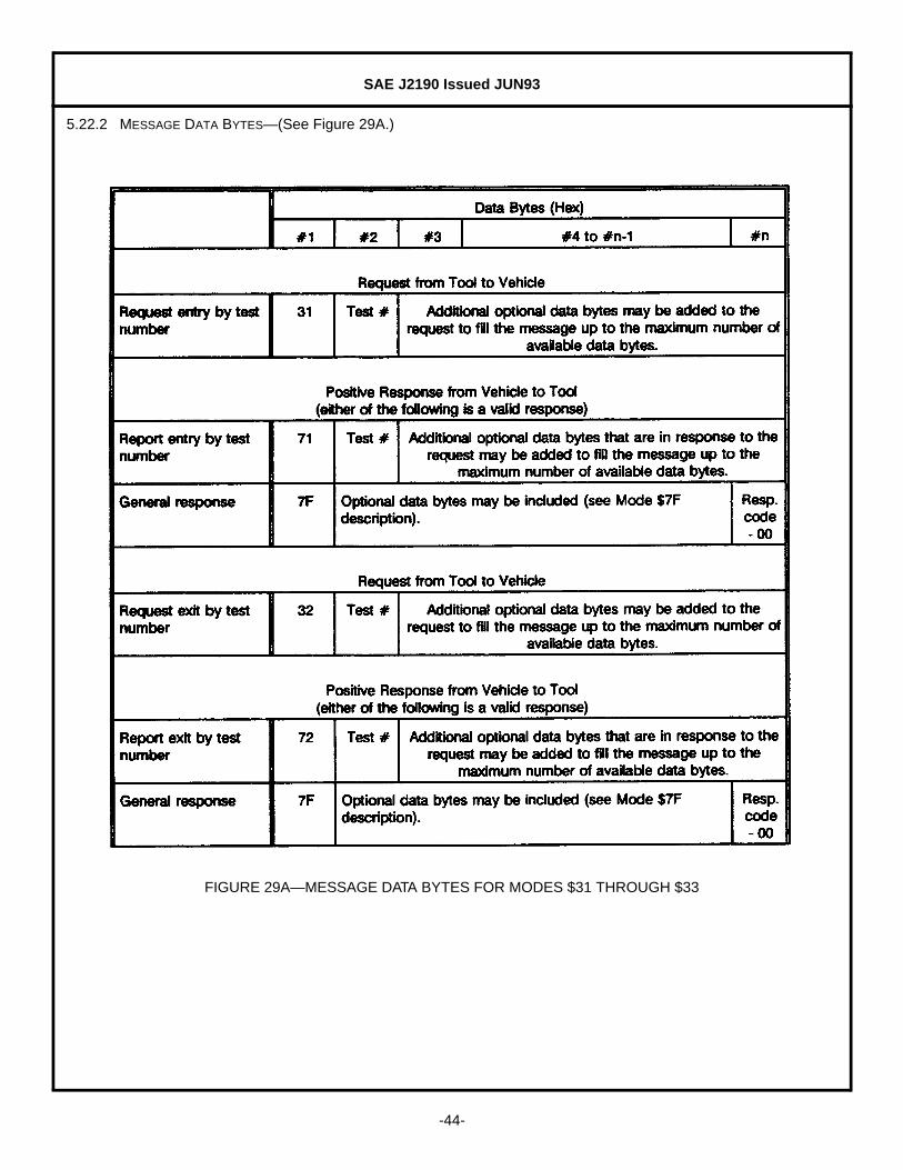
5.22.2 MESSAGE DATA BYTES—(See Figure 29A.)
FIGURE 29A—MESSAGE DATA BYTES FOR MODES $31 THROUGH $33
SAE J2190 Issued JUN93
-45-
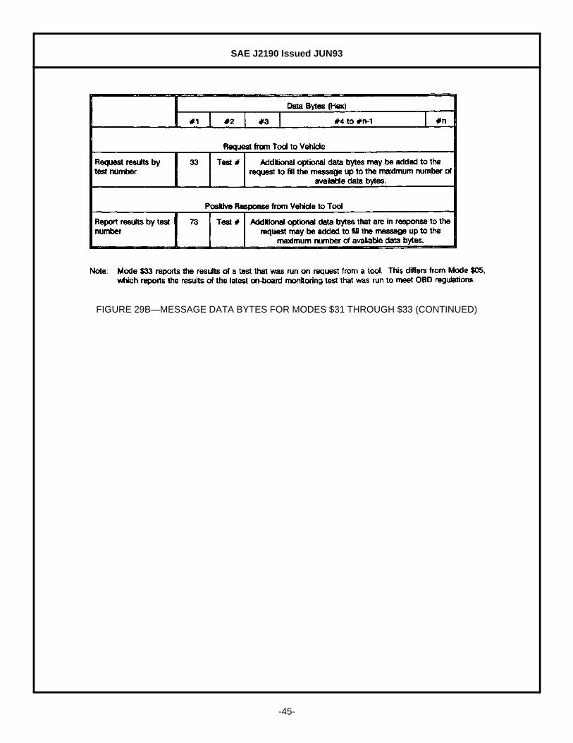
FIGURE 29B—MESSAGE DATA BYTES FOR MODES $31 THROUGH $33 (CONTINUED)
SAE J2190 Issued JUN93
-46-
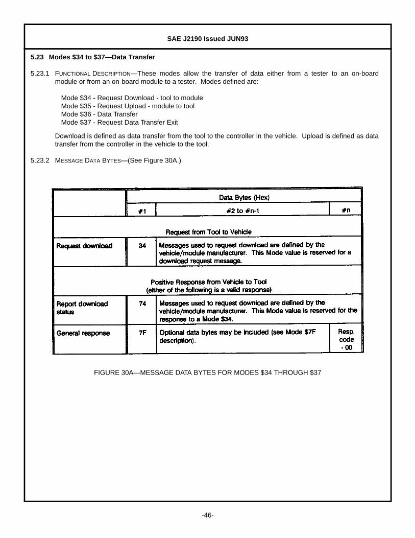
5.23 Modes $34 to $37—Data Transfer
5.23.1 FUNCTIONAL DESCRIPTION—These modes allow the transfer of data either from a tester to an on-boardmodule or from an on-board module to a tester. Modes defined are:
Mode $34 - Request Download - tool to moduleMode $35 - Request Upload - module to toolMode $36 - Data TransferMode $37 - Request Data Transfer Exit
Download is defined as data transfer from the tool to the controller in the vehicle. Upload is defined as datatransfer from the controller in the vehicle to the tool.
5.23.2 MESSAGE DATA BYTES—(See Figure 30A.)
FIGURE 30A—MESSAGE DATA BYTES FOR MODES $34 THROUGH $37

SAE J2190 Issued JUN93
-47-
FIGURE 30B—MESSAGE DATA BYTES FOR MODES $34 THROUGH $37 (CONTINUED)
SAE J2190 Issued JUN93
-48-
5.24 Modes $38 to $3A—Perform Diagnostic Routine at a Specified Address
5.24.1 FUNCTIONAL DESCRIPTION—These test modes are used to execute code resident in the on-board controller atthe specified address. This executable code may be permanently stored in the controller or may have beendownloaded using Modes $34 and $36.
These three sets of messages are used to perform tests resident in an on-board control module. Thesemessages perform three functions:
Mode $38 - Enter Diagnostic Routine by AddressMode $39 - Exit Diagnostic Routine by AddressMode $3A - Request Diagnostic Routine Results
5.24.2 MESSAGE DATA BYTES—(See Figure 31A.)

SAE J2190 Issued JUN93
-49-
FIGURE 31A—MESSAGE DATA BYTES FOR MODES $38 THROUGH $3A
FIGURE 31B—MESSAGE DATA BYTES FOR MODES $38 THROUGH 3A (CONTINUED)

SAE J2190 Issued JUN93
-50-
5.25 Mode $3B—Write Data Block
5.25.1 FUNCTIONAL DESCRIPTION—The purpose of this mode is to provide a means for the external test device tochange the contents of a data block. The data block numbers and associated memory locations need to beknown by the on-board device. This mode does not allow off-board test equipment to change any memorylocations other than for those data blocks predefined in the on-board device.
The number of data bytes included in the request message for each block number depends on the systemdesign and intent of the usage for that block.
Possible uses for this mode are:
Clear non-volatile memoryReset learned values in a single tableSet option contentSet Vehicle Identification Number (VIN)Change calibration values
This mode can be used to clear or reset tables stored in non-volatile memory. A data block number could bedefined as memory locations that need to be either cleared or reset to predefined initial values, such aslearned values in a table. Sending the data block number with no data bytes could cause the on-boardsystem to clear/reset all learned values associated with that data block number to known nominal values.
Another use is to allow the VIN to be input. A data block number could be defined to expect a portion of theVIN. Multiple messages would be required to send the entire 17-character VIN. Whatever data values wereincluded in the request message would be stored in the memory locations known by the on-board system forVIN.
In some systems, this mode could be used for programming calibrations or vehicle specific information in theassembly plant or service without using secured methods for reprogramming. If desired that those valuesnot be changed after production, the capability to modify those data blocks could be disabled after the initialchange.

SAE J2190 Issued JUN93
-51-
5.25.2 MESSAGE DATA BYTES—(See Figure 32.)
FIGURE 32—MESSAGE DATA BYTES FOR MODE $3B

SAE J2190 Issued JUN93
-52-
5.26 Mode $3C—Read Data Block
5.26.1 FUNCTIONAL DESCRIPTION—The purpose of this mode is to provide a means for the external test device toread the contents of a data block. The data block numbers and associated memory locations need to beknown by the on-board device. This mode does not allow off-board test equipment to read any memorylocations other than for those data blocks predefined in the on-board device.
The number of data bytes included in the Response for each block number depends on the system designand intent of the usage for that block.
Possible uses for this mode are to read:
Learned values in a single tableOption contentVehicle Identification Number (VIN)Calibration values
5.26.2 MESSAGE DATA BYTES—(See Figure 33.)
FIGURE 33—MESSAGE DATA BYTES FOR MODE $3C

SAE J2190 Issued JUN93
-53-
5.27 Mode $3F—Test Device Present (no operation performed)
5.27.1 FUNCTIONAL DESCRIPTION—This mode can be used to indicate a tool or test device is present. This messagemay be required, in the absence of other diagnostic messages, to prevent modules from automaticallyreturning to normal operation. The presence of this message will indicate that the system should remain in adiagnostic mode of operation.
This message will normally be sent to all modules in the vehicle. Because this message is not a specificrequest for a controller to do something, There is no required response message to the test tool presentmessage. However, if the message strategy includes a response to this, a general response messageshould be used. If the vehicle contains multiple modules, then multiple responses will be sent, usingavailable data link time.
5.27.2 MESSAGE DATA BYTES—(See Figure 34.)
FIGURE 34—MESSAGE DATA BYTES FOR MODE $3F

SAE J2190 Issued JUN93
-54-
5.28 Mode $7F—General Response Message
5.28.1 FUNCTIONAL DESCRIPTION—Physical requests for information must be responded to by the intended receiverof the request. This message is intended to be a generic response to any request message when data doesnot need to be returned to the test device. This is an alternative to a specific response when the request isfor an action to be performed by the controller. This is also a reject message (negative response) forrequests for data or for an action to be performed. See the "Message Response" section for a more detaileddiscussion about the use of this message.
The response may be an acknowledge that the message was received, or may include a code indicating thereason for rejection if a valid response is not possible. This response assumes that a valid message hasbeen received, and is not intended to inform the sender of an invalid message or to report system failures.Valid response codes are included in this section. Response codes from $00 to $7F are reserved to bedefined in this document, and codes from $80 to $FF are reserved to be defined by the vehicle manufacturer.
The format for the general response message is a $7F for the first data byte after the header, optional databytes that repeat data bytes of the request, and the response code. If a fixed message length is required andthere are not enough data bytes in the request, the message should be padded with $00 to fill the remainingdata bytes.
5.28.2 MESSAGE DATA BYTES—(See Figure 35.)
FIGURE 35—MESSAGE DATA BYTES FOR MODE $7F
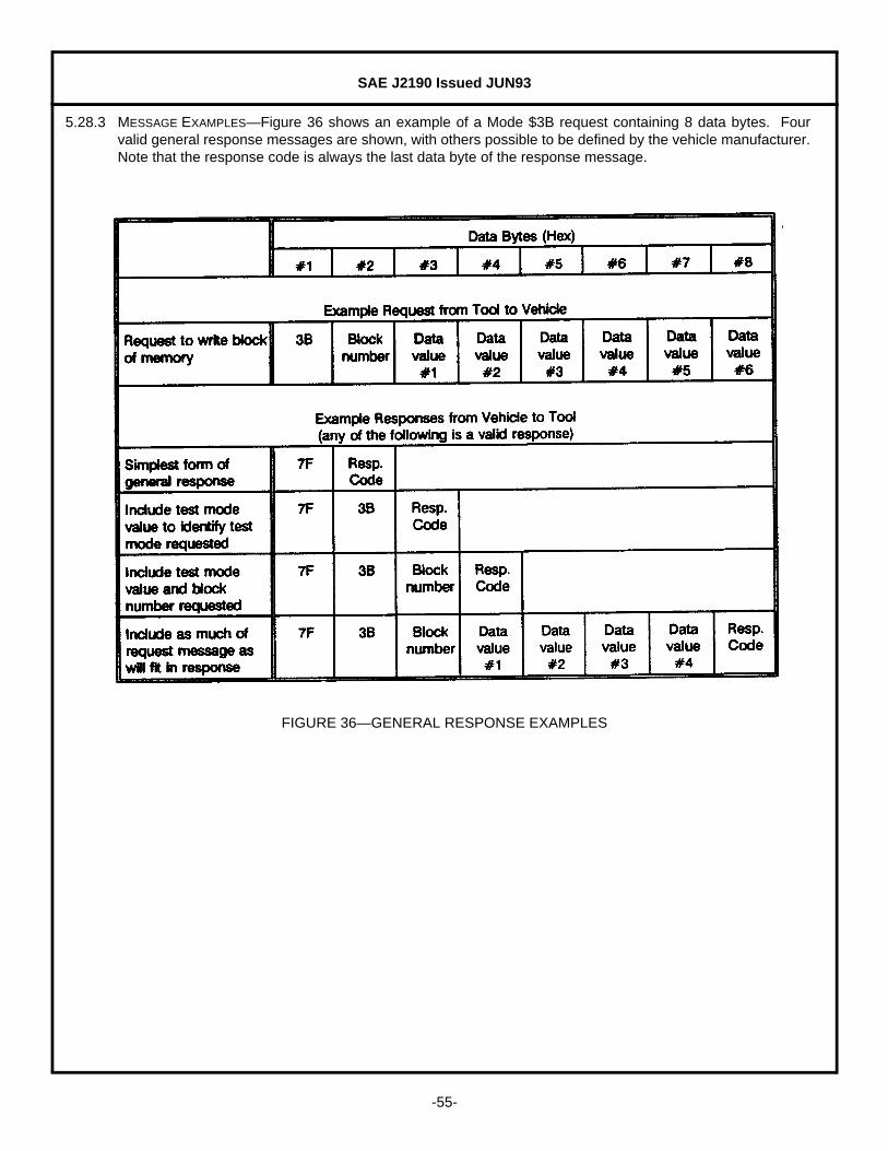
SAE J2190 Issued JUN93
-55-
5.28.3 MESSAGE EXAMPLES—Figure 36 shows an example of a Mode $3B request containing 8 data bytes. Fourvalid general response messages are shown, with others possible to be defined by the vehicle manufacturer.Note that the response code is always the last data byte of the response message.
FIGURE 36—GENERAL RESPONSE EXAMPLES

SAE J2190 Issued JUN93
-56-
5.28.4 RESPONSE CODES—Figure 37 includes response codes and descriptions to be used with the generalresponse messages.
FIGURE 37A—GENERAL RESPONSE CODES

SAE J2190 Issued JUN93
-57-
FIGURE 37B—GENERAL RESPONSE CODES (CONTINUED)

SAE J2190 Issued JUN93
-58-
FIGURE 37C—GENERAL RESPONSE CODES (CONTINUED)

SAE J2190 Issued JUN93
-59-
FIGURE 37D—GENERAL RESPONSE CODES (CONTINUED)

SAE J2190 Issued JUN93
-60-
FIGURE 37E—GENERAL RESPONSE CODES (CONTINUED)
PREPARED BY THE SAE VEHICLE E/E SYSTEM DIAGNOSTICS STANDARDS COMMITTEE
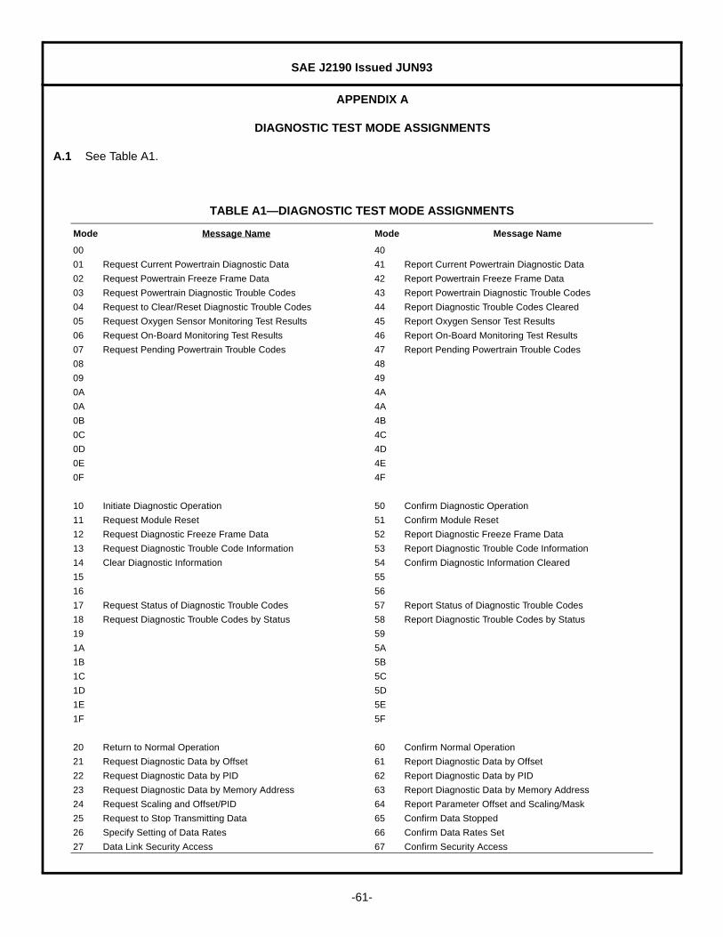
SAE J2190 Issued JUN93
-61-
APPENDIX A
DIAGNOSTIC TEST MODE ASSIGNMENTS
A.1 See Table A1.
TABLE A1—DIAGNOSTIC TEST MODE ASSIGNMENTS
Mode Message Name Mode Message Name
00 40
01 Request Current Powertrain Diagnostic Data 41 Report Current Powertrain Diagnostic Data
02 Request Powertrain Freeze Frame Data 42 Report Powertrain Freeze Frame Data
03 Request Powertrain Diagnostic Trouble Codes 43 Report Powertrain Diagnostic Trouble Codes
04 Request to Clear/Reset Diagnostic Trouble Codes 44 Report Diagnostic Trouble Codes Cleared
05 Request Oxygen Sensor Monitoring Test Results 45 Report Oxygen Sensor Test Results
06 Request On-Board Monitoring Test Results 46 Report On-Board Monitoring Test Results
07 Request Pending Powertrain Trouble Codes 47 Report Pending Powertrain Trouble Codes
08 48
09 49
0A 4A
0A 4A
0B 4B
0C 4C
0D 4D
0E 4E
0F 4F
10 Initiate Diagnostic Operation 50 Confirm Diagnostic Operation
11 Request Module Reset 51 Confirm Module Reset
12 Request Diagnostic Freeze Frame Data 52 Report Diagnostic Freeze Frame Data
13 Request Diagnostic Trouble Code Information 53 Report Diagnostic Trouble Code Information
14 Clear Diagnostic Information 54 Confirm Diagnostic Information Cleared
15 55
16 56
17 Request Status of Diagnostic Trouble Codes 57 Report Status of Diagnostic Trouble Codes
18 Request Diagnostic Trouble Codes by Status 58 Report Diagnostic Trouble Codes by Status
19 59
1A 5A
1B 5B
1C 5C
1D 5D
1E 5E
1F 5F
20 Return to Normal Operation 60 Confirm Normal Operation
21 Request Diagnostic Data by Offset 61 Report Diagnostic Data by Offset
22 Request Diagnostic Data by PID 62 Report Diagnostic Data by PID
23 Request Diagnostic Data by Memory Address 63 Report Diagnostic Data by Memory Address
24 Request Scaling and Offset/PID 64 Report Parameter Offset and Scaling/Mask
25 Request to Stop Transmitting Data 65 Confirm Data Stopped
26 Specify Setting of Data Rates 66 Confirm Data Rates Set
27 Data Link Security Access 67 Confirm Security Access
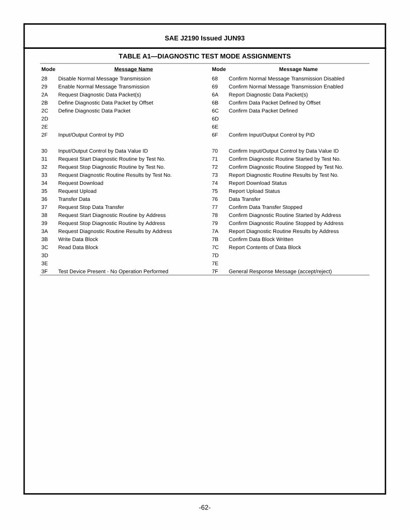
SAE J2190 Issued JUN93
-62-
28 Disable Normal Message Transmission 68 Confirm Normal Message Transmission Disabled
29 Enable Normal Message Transmission 69 Confirm Normal Message Transmission Enabled
2A Request Diagnostic Data Packet(s) 6A Report Diagnostic Data Packet(s)
2B Define Diagnostic Data Packet by Offset 6B Confirm Data Packet Defined by Offset
2C Define Diagnostic Data Packet 6C Confirm Data Packet Defined
2D 6D
2E 6E
2F Input/Output Control by PID 6F Confirm Input/Output Control by PID
30 Input/Output Control by Data Value ID 70 Confirm Input/Output Control by Data Value ID
31 Request Start Diagnostic Routine by Test No. 71 Confirm Diagnostic Routine Started by Test No.
32 Request Stop Diagnostic Routine by Test No. 72 Confirm Diagnostic Routine Stopped by Test No.
33 Request Diagnostic Routine Results by Test No. 73 Report Diagnostic Routine Results by Test No.
34 Request Download 74 Report Download Status
35 Request Upload 75 Report Upload Status
36 Transfer Data 76 Data Transfer
37 Request Stop Data Transfer 77 Confirm Data Transfer Stopped
38 Request Start Diagnostic Routine by Address 78 Confirm Diagnostic Routine Started by Address
39 Request Stop Diagnostic Routine by Address 79 Confirm Diagnostic Routine Stopped by Address
3A Request Diagnostic Routine Results by Address 7A Report Diagnostic Routine Results by Address
3B Write Data Block 7B Confirm Data Block Written
3C Read Data Block 7C Report Contents of Data Block
3D 7D
3E 7E
3F Test Device Present - No Operation Performed 7F General Response Message (accept/reject)
TABLE A1—DIAGNOSTIC TEST MODE ASSIGNMENTS
Mode Message Name Mode Message Name

SAE J2190 Issued JUN93
Rationale—Not applicable.
Relationship of SAE Standard to ISO Standard—Not applicable.
Application—This SAE Recommended Practice describes the implementation of Enhanced Diagnostic TestModes, which are intended to supplement the legislated Diagnostic Test Modes defined in SAE J1979.Modes are defined for access to emission related test data beyond what is included in SAE J1979, andfor non-emission related data. This document describes the data byte values for diagnostic messagestransmitted between diagnostic test equipment, either on-vehicle or off-vehicle, and vehicle electroniccontrol modules. No distinction is made between test modes for emission related and non-emissionrelated diagnostics. These messages can be used with a diagnostic serial data link such as described inSAE J1850 or ISO 9141-2.
For each test mode, this document includes a functional description of the test mode, request and reportmessage data byte content, and an example if useful for clarification.
Reference Section
SAE J1850—Class B Data Communication Network Interface
SAE J1930—E/E Systems Diagnostic Terms, Definitions, Abbreviations and Acronyms
SAE J1962—Diagnostic Connector
SAE J1978—OBD II Scan Tool
SAE J1979—E/E Diagnostic Test Modes
SAE J2012—Recommended Format and Messages for Diagnostic Trouble Codes
SAE J2178—Class B Data Communication Network Messages
SAE J2186—E/E Data Link Security
ISO 9141-2—Road vehicles—Diagnostic systems—CARB requirements for interchange of digitalinformation ANSI/IEEE Std. 754-1985
Mail out #93-27—Title 13, California Code of Regulations, Section 1968.1 Malfunction and DiagnosticSystem
May 21, 1993 Requirements—1994 and Subsequent Model-Year Passenger Cars, Light-Duty Trucks,and Medium-Duty Vehicles and Engines
40 CFR Part 86—Control of Air Pollution From New Motor Vehicles and New Motor Vehicle Engines;Federal Register Regulations Requiring On-board Diagnostic
Developed by the SAE Vehicle E/E System Diagnostics Standards Committee

![X10 Tester - · PDF fileX10_Tester.can Page 3 of 128. 151 BYTE hasToSendWriteColumnConfig = 0; 152 BYTE hasToSendWriteColumnDefault = 0; 153 154 BYTE StartLogicControl[6]; 155 BYTE](https://static.fdocuments.us/doc/165x107/5aa9f1037f8b9a9a188d968e/x10-tester-page-3-of-128-151-byte-hastosendwritecolumnconfig-0-152-byte-hastosendwritecolumndefault.jpg)