Surface & Coatings...
5
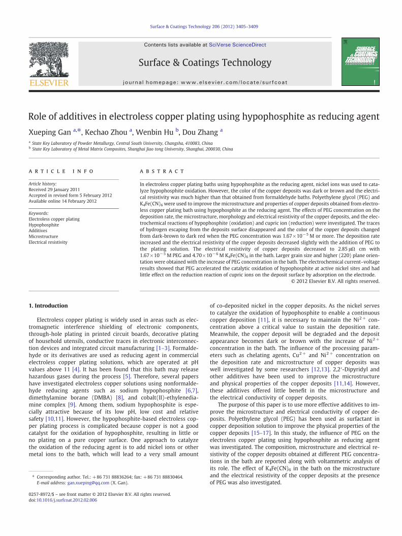
Role of additives in electroless copper plating using hypophosphite as reducing agent Xueping Gan a, ⁎, Kechao Zhou a , Wenbin Hu b , Dou Zhang a a State Key Laboratory of Powder Metallurgy, Central South University, Changsha, 410083, China b State Key Laboratory of Metal Matrix Composites, Shanghai Jiao tong University, Shanghai, 200030, China abstract article info Article history: Received 29 January 2011 Accepted in revised form 5 February 2012 Available online 14 February 2012 Keywords: Electroless copper plating Hypophosphite Additives Microstructure Electrical resistivity In electroless copper plating baths using hypophosphite as the reducing agent, nickel ions was used to cata- lyze hypophosphite oxidation. However, the color of the copper deposits was dark or brown and the electri- cal resistivity was much higher than that obtained from formaldehyde baths. Polyethylene glycol (PEG) and K 4 Fe(CN) 6 were used to improve the microstructure and properties of copper deposits obtained from electro- less copper plating bath using hypophosphite as the reducing agent. The effects of PEG concentration on the deposition rate, the microstructure, morphology and electrical resistivity of the copper deposits, and the elec- trochemical reactions of hypophosphite (oxidation) and cupric ion (reduction) were investigated. The traces of hydrogen escaping from the deposits surface disappeared and the color of the copper deposits changed from dark-brown to dark red when the PEG concentration was 1.67 × 10 −5 M or more. The deposition rate increased and the electrical resistivity of the copper deposits decreased slightly with the addition of PEG to the plating solution. The electrical resistivity of copper deposits decreased to 2.85 μΩ cm with 1.67 × 10 −5 M PEG and 4.70 × 10 −6 MK 4 Fe(CN) 6 in the bath. Larger grain size and higher (220) plane orien- tation were obtained with the increase of PEG concentration in the bath. The electrochemical current–voltage results showed that PEG accelerated the catalytic oxidation of hypophosphite at active nickel sites and had little effect on the reduction reaction of cupric ions on the deposit surface by adsorption on the electrode. © 2012 Elsevier B.V. All rights reserved. 1. Introduction Electroless copper plating is widely used in areas such as elec- tromagnetic interference shielding of electronic components, through-hole plating in printed circuit boards, decorative plating of household utensils, conductive traces in electronic interconnec- tion devices and integrated circuit manufacturing [1–3]. Formalde- hyde or its derivatives are used as reducing agent in commercial electroless copper plating solutions, which are operated at pH values above 11 [4]. It has been found that this bath may release hazardous gases during the process [5]. Therefore, several papers have investigated electroless copper solutions using nonformalde- hyde reducing agents such as sodium hypophosphite [6,7], dimethylamine borane (DMBA) [8], and cobalt(II)-ethylenedia- mine complex [9]. Among them, sodium hypophosphite is espe- cially attractive because of its low pH, low cost and relative safety [10,11]. However, the hypophosphite-based electroless cop- per plating process is complicated because copper is not a good catalyst for the oxidation of hypophosphite, resulting in little or no plating on a pure copper surface. One approach to catalyze the oxidation of the reducing agent is to add nickel ions or other metal ions to the bath, which will lead to a very small amount of co-deposited nickel in the copper deposits. As the nickel serves to catalyze the oxidation of hypophosphite to enable a continuous copper deposition [11], it is necessary to maintain the Ni 2+ con- centration above a critical value to sustain the deposition rate. Meanwhile, the copper deposit will be degraded and the deposit appearance becomes dark or brown with the increase of Ni 2+ concentration in the bath. The influence of the processing param- eters such as chelating agents, Cu 2+ and Ni 2+ concentration on the deposition rate and microstructure of copper deposits was well investigated by some researchers [12,13]. 2,2′-Dipyridyl and other additives have been used to improve the microstructure and physical properties of the copper deposits [11,14]. However, these additives offered little benefit in the microstructure and the electrical conductivity of copper deposits. The purpose of this paper is to use more effective additives to im- prove the microstructure and electrical conductivity of copper de- posits. Polyethylene glycol (PEG) has been used as surfactant in copper deposition solution to improve the physical properties of the copper deposits [15–17]. In this study, the influence of PEG on the electroless copper plating using hypophosphite as reducing agent was investigated. The composition, microstructure and electrical re- sistivity of the copper deposits obtained at different PEG concentra- tions in the bath are reported along with voltammetric analysis of its role. The effect of K 4 Fe(CN) 6 in the bath on the microstructure and the electrical resistivity of the copper deposits at the presence of PEG was also investigated. Surface & Coatings Technology 206 (2012) 3405–3409 ⁎ Corresponding author. Tel.: + 86 731 88836264; fax: + 86 731 88830464. E-mail address: [email protected] (X. Gan). 0257-8972/$ – see front matter © 2012 Elsevier B.V. All rights reserved. doi:10.1016/j.surfcoat.2012.02.006 Contents lists available at SciVerse ScienceDirect Surface & Coatings Technology journal homepage: www.elsevier.com/locate/surfcoat
Transcript of Surface & Coatings...
Surface & Coatings Technology 206 (2012) 3405–3409
Contents lists available at SciVerse ScienceDirect
Surface & Coatings Technology
j ourna l homepage: www.e lsev ie r .com/ locate /sur fcoat
Role of additives in electroless copper plating using hypophosphite as reducing agent
Xueping Gan a,⁎, Kechao Zhou a, Wenbin Hu b, Dou Zhang a
a State Key Laboratory of Powder Metallurgy, Central South University, Changsha, 410083, Chinab State Key Laboratory of Metal Matrix Composites, Shanghai Jiao tong University, Shanghai, 200030, China
⁎ Corresponding author. Tel.: +86 731 88836264; faxE-mail address: [email protected] (X. Gan).
0257-8972/$ – see front matter © 2012 Elsevier B.V. Alldoi:10.1016/j.surfcoat.2012.02.006
a b s t r a c t
a r t i c l e i n f oArticle history:Received 29 January 2011Accepted in revised form 5 February 2012Available online 14 February 2012
Keywords:Electroless copper platingHypophosphiteAdditivesMicrostructureElectrical resistivity
In electroless copper plating baths using hypophosphite as the reducing agent, nickel ions was used to cata-lyze hypophosphite oxidation. However, the color of the copper deposits was dark or brown and the electri-cal resistivity was much higher than that obtained from formaldehyde baths. Polyethylene glycol (PEG) andK4Fe(CN)6 were used to improve the microstructure and properties of copper deposits obtained from electro-less copper plating bath using hypophosphite as the reducing agent. The effects of PEG concentration on thedeposition rate, the microstructure, morphology and electrical resistivity of the copper deposits, and the elec-trochemical reactions of hypophosphite (oxidation) and cupric ion (reduction) were investigated. The tracesof hydrogen escaping from the deposits surface disappeared and the color of the copper deposits changedfrom dark-brown to dark red when the PEG concentration was 1.67×10⁻⁵ M or more. The deposition rateincreased and the electrical resistivity of the copper deposits decreased slightly with the addition of PEG tothe plating solution. The electrical resistivity of copper deposits decreased to 2.85 μΩ cm with1.67×10−5 M PEG and 4.70×10⁻⁶ M K4Fe(CN)6 in the bath. Larger grain size and higher (220) plane orien-tation were obtained with the increase of PEG concentration in the bath. The electrochemical current–voltageresults showed that PEG accelerated the catalytic oxidation of hypophosphite at active nickel sites and hadlittle effect on the reduction reaction of cupric ions on the deposit surface by adsorption on the electrode.
© 2012 Elsevier B.V. All rights reserved.
1. Introduction
Electroless copper plating is widely used in areas such as elec-tromagnetic interference shielding of electronic components,through-hole plating in printed circuit boards, decorative platingof household utensils, conductive traces in electronic interconnec-tion devices and integrated circuit manufacturing [1–3]. Formalde-hyde or its derivatives are used as reducing agent in commercialelectroless copper plating solutions, which are operated at pHvalues above 11 [4]. It has been found that this bath may releasehazardous gases during the process [5]. Therefore, several papershave investigated electroless copper solutions using nonformalde-hyde reducing agents such as sodium hypophosphite [6,7],dimethylamine borane (DMBA) [8], and cobalt(II)-ethylenedia-mine complex [9]. Among them, sodium hypophosphite is espe-cially attractive because of its low pH, low cost and relativesafety [10,11]. However, the hypophosphite-based electroless cop-per plating process is complicated because copper is not a goodcatalyst for the oxidation of hypophosphite, resulting in little orno plating on a pure copper surface. One approach to catalyzethe oxidation of the reducing agent is to add nickel ions or othermetal ions to the bath, which will lead to a very small amount
: +86 731 88830464.
rights reserved.
of co-deposited nickel in the copper deposits. As the nickel servesto catalyze the oxidation of hypophosphite to enable a continuouscopper deposition [11], it is necessary to maintain the Ni2+ con-centration above a critical value to sustain the deposition rate.Meanwhile, the copper deposit will be degraded and the depositappearance becomes dark or brown with the increase of Ni2+
concentration in the bath. The influence of the processing param-eters such as chelating agents, Cu2+ and Ni2+ concentration onthe deposition rate and microstructure of copper deposits waswell investigated by some researchers [12,13]. 2,2′-Dipyridyl andother additives have been used to improve the microstructureand physical properties of the copper deposits [11,14]. However,these additives offered little benefit in the microstructure andthe electrical conductivity of copper deposits.
The purpose of this paper is to use more effective additives to im-prove the microstructure and electrical conductivity of copper de-posits. Polyethylene glycol (PEG) has been used as surfactant incopper deposition solution to improve the physical properties of thecopper deposits [15–17]. In this study, the influence of PEG on theelectroless copper plating using hypophosphite as reducing agentwas investigated. The composition, microstructure and electrical re-sistivity of the copper deposits obtained at different PEG concentra-tions in the bath are reported along with voltammetric analysis ofits role. The effect of K4Fe(CN)6 in the bath on the microstructureand the electrical resistivity of the copper deposits at the presenceof PEG was also investigated.
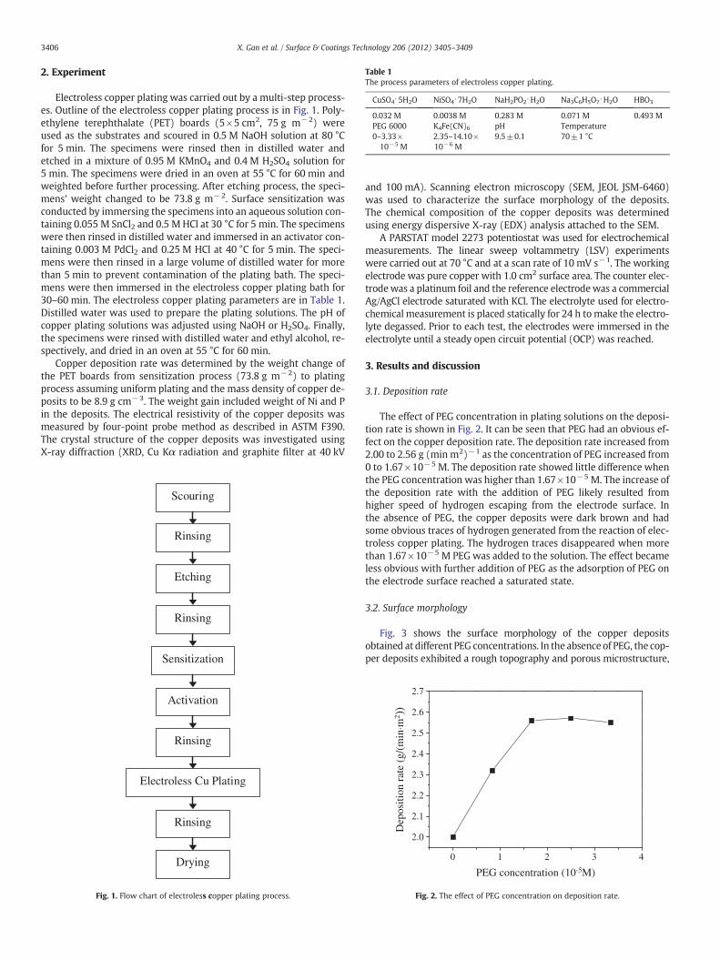
Table 1The process parameters of electroless copper plating.
CuSO4⋅5H2O NiSO4⋅7H2O NaH2PO2⋅H2O Na3C6H5O7⋅H2O HBO3
0.032 M 0.0038 M 0.283 M 0.071 M 0.493 MPEG 6000 K4Fe(CN)6 pH Temperature0–3.33×10⁻⁵ M
2.35–14.10×10⁻⁶ M
9.5±0.1 70±1 °C
3406 X. Gan et al. / Surface & Coatings Technology 206 (2012) 3405–3409
2. Experiment
Electroless copper plating was carried out by a multi-step process-es. Outline of the electroless copper plating process is in Fig. 1. Poly-ethylene terephthalate (PET) boards (5×5 cm2, 75 g m−2) wereused as the substrates and scoured in 0.5 M NaOH solution at 80 °Cfor 5 min. The specimens were rinsed then in distilled water andetched in a mixture of 0.95 M KMnO4 and 0.4 M H2SO4 solution for5 min. The specimens were dried in an oven at 55 °C for 60 min andweighted before further processing. After etching process, the speci-mens' weight changed to be 73.8 g m−2. Surface sensitization wasconducted by immersing the specimens into an aqueous solution con-taining 0.055 M SnCl2 and 0.5 M HCl at 30 °C for 5 min. The specimenswere then rinsed in distilled water and immersed in an activator con-taining 0.003 M PdCl2 and 0.25 M HCl at 40 °C for 5 min. The speci-mens were then rinsed in a large volume of distilled water for morethan 5 min to prevent contamination of the plating bath. The speci-mens were then immersed in the electroless copper plating bath for30–60 min. The electroless copper plating parameters are in Table 1.Distilled water was used to prepare the plating solutions. The pH ofcopper plating solutions was adjusted using NaOH or H2SO4. Finally,the specimens were rinsed with distilled water and ethyl alcohol, re-spectively, and dried in an oven at 55 °C for 60 min.
Copper deposition rate was determined by the weight change ofthe PET boards from sensitization process (73.8 g m−2) to platingprocess assuming uniform plating and the mass density of copper de-posits to be 8.9 g cm−3. The weight gain included weight of Ni and Pin the deposits. The electrical resistivity of the copper deposits wasmeasured by four-point probe method as described in ASTM F390.The crystal structure of the copper deposits was investigated usingX-ray diffraction (XRD, Cu Kα radiation and graphite filter at 40 kV
Scouring
Rinsing
Etching
Rinsing
Activation
Rinsing
Rinsing
Electroless Cu Plating
Sensitization
Drying
Fig. 1. Flow chart of electroless copper plating process.
and 100 mA). Scanning electron microscopy (SEM, JEOL JSM-6460)was used to characterize the surface morphology of the deposits.The chemical composition of the copper deposits was determinedusing energy dispersive X-ray (EDX) analysis attached to the SEM.
A PARSTAT model 2273 potentiostat was used for electrochemicalmeasurements. The linear sweep voltammetry (LSV) experimentswere carried out at 70 °C and at a scan rate of 10 mV s−1. The workingelectrode was pure copper with 1.0 cm2 surface area. The counter elec-trodewas a platinum foil and the reference electrodewas a commercialAg/AgCl electrode saturated with KCl. The electrolyte used for electro-chemical measurement is placed statically for 24 h tomake the electro-lyte degassed. Prior to each test, the electrodes were immersed in theelectrolyte until a steady open circuit potential (OCP) was reached.
3. Results and discussion
3.1. Deposition rate
The effect of PEG concentration in plating solutions on the deposi-tion rate is shown in Fig. 2. It can be seen that PEG had an obvious ef-fect on the copper deposition rate. The deposition rate increased from2.00 to 2.56 g (min m2)−1 as the concentration of PEG increased from0 to 1.67×10⁻⁵ M. The deposition rate showed little difference whenthe PEG concentration was higher than 1.67×10⁻⁵ M. The increase ofthe deposition rate with the addition of PEG likely resulted fromhigher speed of hydrogen escaping from the electrode surface. Inthe absence of PEG, the copper deposits were dark brown and hadsome obvious traces of hydrogen generated from the reaction of elec-troless copper plating. The hydrogen traces disappeared when morethan 1.67×10⁻⁵ M PEG was added to the solution. The effect becameless obvious with further addition of PEG as the adsorption of PEG onthe electrode surface reached a saturated state.
3.2. Surface morphology
Fig. 3 shows the surface morphology of the copper depositsobtained at different PEG concentrations. In the absence of PEG, the cop-per deposits exhibited a rough topography and porous microstructure,
0 1 2 3 4
2.0
2.1
2.2
2.3
2.4
2.5
2.6
2.7
Dep
ositi
on r
ate
(g/(
min
·m2 )
)
PEG concentration (10-5M)
Fig. 2. The effect of PEG concentration on deposition rate.
10um
2um
a b
c d
10um
10um10um
e
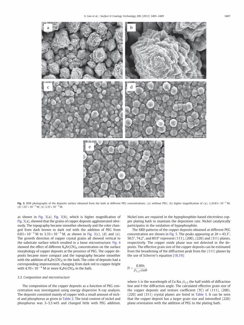
Fig. 3. SEM photographs of the deposits surface obtained from the bath at different PEG concentrations: (a) without PEG; (b) higher magnification of (a); (c)0.83×10⁻⁵ M;(d) 1.67×10⁻⁵ M; (e) 3.33×10⁻⁵ M.
3407X. Gan et al. / Surface & Coatings Technology 206 (2012) 3405–3409
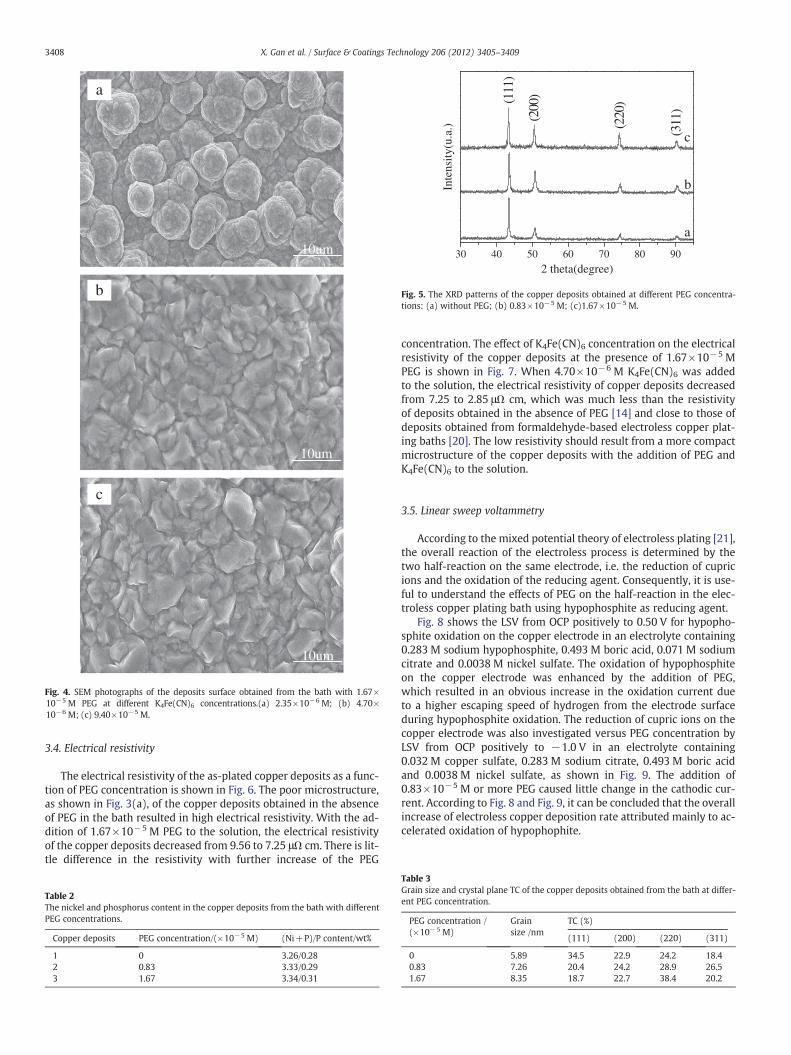
as shown in Fig. 3(a). Fig. 3(b), which is higher magnification ofFig. 3(a), showed that the grains of copper deposits agglomerated obvi-ously. The topography became smoother obviously and the color chan-ged from dark brown to dark red with the addition of PEG from0.83×10−5 M to 3.33×10⁻⁵ M, as shown in Fig. 3(c), (d) and (e).The growth direction of copper crystal grains all showed vertical tothe substrate surface which resulted in a loose microstructure. Fig. 4showed the effect of different K4Fe(CN)6 concentration on the surfacemorphology of copper deposits at the presence of PEG. The copper de-posits became more compact and the topography became smootherwith the addition of K4Fe(CN)6 to the bath. The color of deposits had acorresponding improvement, changing from dark red to copper-brightwith 4.70×10⁻⁶ M or more K4Fe(CN)6 in the bath.
3.3. Composition and microstructure
The composition of the copper deposits as a function of PEG con-centration was investigated using energy dispersive X-ray analysis.The deposits consisted mainly of copper with a small amount of nick-el and phosphorus as given in Table 2. The total content of nickel andphosphorus was 3–3.5 wt% and changed little with PEG addition.
Nickel ions are required in the hypophosphite-based electroless cop-per plating bath to maintain the deposition rate. Nickel catalyticallyparticipates in the oxidation of hypophosphite.
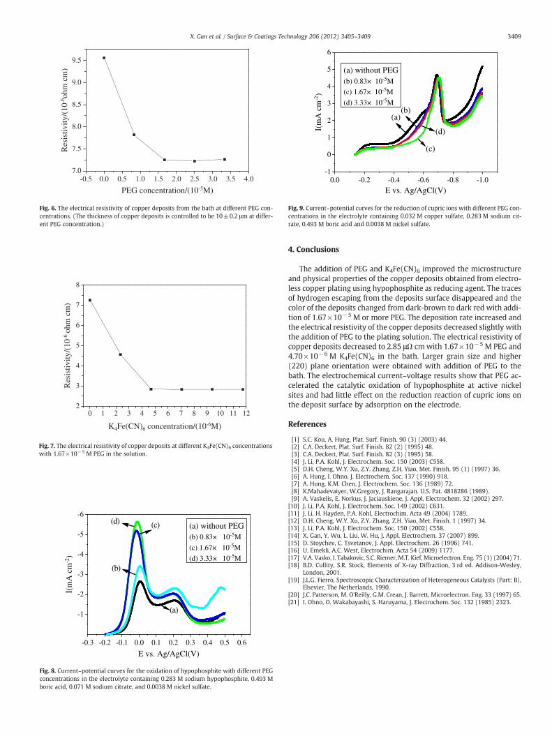
The XRD patterns of the copper deposits obtained at different PEGconcentration are shown in Fig. 5. The peaks appearing at 2θ=43.3°,50.5°, 74.2°, and 89.9° represent (111), (200), (220) and (311) planes,respectively. The copper oxide phase was not detected in the de-posits. The effective grain size of the copper deposits can be estimatedfrom the broadening of the diffraction peak from the (111) planes bythe use of Scherrer's equation [18,19]:
D ¼ 0:89λβ1=2 cosθ
where λ is the wavelength of Cu Kα, β1/2 the half width of diffractionline and θ the diffraction angle. The calculated effective grain size ofthe copper deposits and texture coefficient (TC) of (111), (200),(220) and (311) crystal planes are listed in Table 3. It can be seenthat the copper deposit has a larger grain size and intensified (220)plane orientation with the addition of PEG to the plating bath.
c
b
a
10um
10um
10um
Fig. 4. SEM photographs of the deposits surface obtained from the bath with 1.67×10⁻⁵ M PEG at different K4Fe(CN)6 concentrations.(a) 2.35×10⁻⁶ M; (b) 4.70×10⁻⁶ M; (c) 9.40×10⁻⁵ M.
30 40 50 60 70 80 90
(311
)
(220
)
(200
)(111
)
c
b
a
Inte
nsity
(u.a
.)
2 theta(degree)
Fig. 5. The XRD patterns of the copper deposits obtained at different PEG concentra-tions: (a) without PEG; (b) 0.83×10⁻⁵ M; (c)1.67×10⁻⁵ M.
3408 X. Gan et al. / Surface & Coatings Technology 206 (2012) 3405–3409
3.4. Electrical resistivity
The electrical resistivity of the as-plated copper deposits as a func-tion of PEG concentration is shown in Fig. 6. The poor microstructure,as shown in Fig. 3(a), of the copper deposits obtained in the absenceof PEG in the bath resulted in high electrical resistivity. With the ad-dition of 1.67×10⁻⁵ M PEG to the solution, the electrical resistivityof the copper deposits decreased from 9.56 to 7.25 μΩ cm. There is lit-tle difference in the resistivity with further increase of the PEG
Table 2The nickel and phosphorus content in the copper deposits from the bath with differentPEG concentrations.
Copper deposits PEG concentration/(×10−5 M) (Ni+P)/P content/wt%
1 0 3.26/0.282 0.83 3.33/0.293 1.67 3.34/0.31
concentration. The effect of K4Fe(CN)6 concentration on the electricalresistivity of the copper deposits at the presence of 1.67×10⁻⁵ MPEG is shown in Fig. 7. When 4.70×10⁻⁶ M K4Fe(CN)6 was addedto the solution, the electrical resistivity of copper deposits decreasedfrom 7.25 to 2.85 μΩ cm, which was much less than the resistivityof deposits obtained in the absence of PEG [14] and close to those ofdeposits obtained from formaldehyde-based electroless copper plat-ing baths [20]. The low resistivity should result from a more compactmicrostructure of the copper deposits with the addition of PEG andK4Fe(CN)6 to the solution.
3.5. Linear sweep voltammetry
According to the mixed potential theory of electroless plating [21],the overall reaction of the electroless process is determined by thetwo half-reaction on the same electrode, i.e. the reduction of cupricions and the oxidation of the reducing agent. Consequently, it is use-ful to understand the effects of PEG on the half-reaction in the elec-troless copper plating bath using hypophosphite as reducing agent.
Fig. 8 shows the LSV from OCP positively to 0.50 V for hypopho-sphite oxidation on the copper electrode in an electrolyte containing0.283 M sodium hypophosphite, 0.493 M boric acid, 0.071 M sodiumcitrate and 0.0038 M nickel sulfate. The oxidation of hypophosphiteon the copper electrode was enhanced by the addition of PEG,which resulted in an obvious increase in the oxidation current dueto a higher escaping speed of hydrogen from the electrode surfaceduring hypophosphite oxidation. The reduction of cupric ions on thecopper electrode was also investigated versus PEG concentration byLSV from OCP positively to −1.0 V in an electrolyte containing0.032 M copper sulfate, 0.283 M sodium citrate, 0.493 M boric acidand 0.0038 M nickel sulfate, as shown in Fig. 9. The addition of0.83×10−5 M or more PEG caused little change in the cathodic cur-rent. According to Fig. 8 and Fig. 9, it can be concluded that the overallincrease of electroless copper deposition rate attributed mainly to ac-celerated oxidation of hypophophite.
Table 3Grain size and crystal plane TC of the copper deposits obtained from the bath at differ-ent PEG concentration.
PEG concentration /(×10−5 M)
Grainsize /nm
TC (%)
(111) (200) (220) (311)
0 5.89 34.5 22.9 24.2 18.40.83 7.26 20.4 24.2 28.9 26.51.67 8.35 18.7 22.7 38.4 20.2
-0.5 0.0 0.5 1.0 1.5 2.0 2.5 3.0 3.5 4.07.0
7.5
8.0
8.5
9.0
9.5R
esis
tivity
/(10
-6oh
m c
m)
PEG concentration/(10-5M)
Fig. 6. The electrical resistivity of copper deposits from the bath at different PEG con-centrations. (The thickness of copper deposits is controlled to be 10±0.2 μm at differ-ent PEG concentration.)
0 1 2 3 4 5 6 7 8 9 10 11 122
3
4
5
6
7
8
Res
istiv
ity/(
10-6
ohm
cm
)
K4Fe(CN)6 concentration/(10-6M)
Fig. 7. The electrical resistivity of copper deposits at different K4Fe(CN)6 concentrationswith 1.67×10⁻⁵ M PEG in the solution.
-0.3 -0.2 -0.1 0.0 0.1 0.2 0.3 0.4 0.5 0.6
-1
-2
-3
-4
-5
-6
I(m
A c
m-2
)
E vs. Ag/AgCl(V)
(a)
(b)
(c)(d)(a) without PEG(b) 0.83× 10⁻⁵M
(c) 1.67× 10⁻⁵M
(d) 3.33× 10⁻⁵M
Fig. 8. Current–potential curves for the oxidation of hypophosphite with different PEGconcentrations in the electrolyte containing 0.283 M sodium hypophosphite, 0.493 Mboric acid, 0.071 M sodium citrate, and 0.0038 M nickel sulfate.
0.0 -0.2 -0.4 -0.6 -0.8 -1.0-1
0
1
2
3
4
5
6
(a) without PEG(b) 0.83× 10⁻⁵M
(c) 1.67× 10⁻⁵M
(d) 3.33× 10⁻⁵M
I(m
A c
m-2
)
E vs. Ag/AgCl(V)
(a)(b)
(c)
(d)
Fig. 9. Current–potential curves for the reduction of cupric ions with different PEG con-centrations in the electrolyte containing 0.032 M copper sulfate, 0.283 M sodium cit-rate, 0.493 M boric acid and 0.0038 M nickel sulfate.
3409X. Gan et al. / Surface & Coatings Technology 206 (2012) 3405–3409
4. Conclusions
The addition of PEG and K4Fe(CN)6 improved the microstructureand physical properties of the copper deposits obtained from electro-less copper plating using hypophosphite as reducing agent. The tracesof hydrogen escaping from the deposits surface disappeared and thecolor of the deposits changed from dark-brown to dark red with addi-tion of 1.67×10⁻⁵ M or more PEG. The deposition rate increased andthe electrical resistivity of the copper deposits decreased slightly withthe addition of PEG to the plating solution. The electrical resistivity ofcopper deposits decreased to 2.85 μΩ cmwith 1.67×10⁻⁵ M PEG and4.70×10−6 M K4Fe(CN)6 in the bath. Larger grain size and higher(220) plane orientation were obtained with addition of PEG to thebath. The electrochemical current–voltage results show that PEG ac-celerated the catalytic oxidation of hypophosphite at active nickelsites and had little effect on the reduction reaction of cupric ions onthe deposit surface by adsorption on the electrode.
References
[1] S.C. Kou, A. Hung, Plat. Surf. Finish. 90 (3) (2003) 44.[2] C.A. Deckert, Plat. Surf. Finish. 82 (2) (1995) 48.[3] C.A. Deckert, Plat. Surf. Finish. 82 (3) (1995) 58.[4] J. Li, P.A. Kohl, J. Electrochem. Soc. 150 (2003) C558.[5] D.H. Cheng, W.Y. Xu, Z.Y. Zhang, Z.H. Yiao, Met. Finish. 95 (1) (1997) 36.[6] A. Hung, I. Ohno, J. Electrochem. Soc. 137 (1990) 918.[7] A. Hung, K.M. Chen, J. Electrochem. Soc. 136 (1989) 72.[8] K.Mahadevaiyer, W.Gregory, J. Rangarajan. U.S. Pat. 4818286 (1989).[9] A. Vaskelis, E. Norkus, J. Jaciauskiene, J. Appl. Electrochem. 32 (2002) 297.
[10] J. Li, P.A. Kohl, J. Electrochem. Soc. 149 (2002) C631.[11] J. Li, H. Hayden, P.A. Kohl, Electrochim. Acta 49 (2004) 1789.[12] D.H. Cheng, W.Y. Xu, Z.Y. Zhang, Z.H. Yiao, Met. Finish. 1 (1997) 34.[13] J. Li, P.A. Kohl, J. Electrochem. Soc. 150 (2002) C558.[14] X. Gan, Y. Wu, L. Liu, W. Hu, J. Appl. Electrochem. 37 (2007) 899.[15] D. Stoychev, C. Tsvetanov, J. Appl. Electrochem. 26 (1996) 741.[16] U. Emekli, A.C. West, Electrochim. Acta 54 (2009) 1177.[17] V.A. Vasko, I. Tabakovic, S.C. Riemer, M.T. Kief, Microelectron. Eng. 75 (1) (2004) 71.[18] B.D. Cullity, S.R. Stock, Elements of X-ray Diffraction, 3 rd ed. Addison-Wesley,
London, 2001.[19] J.L.G. Fierro, Spectroscopic Characterization of Heterogeneous Catalysts (Part: B),
Elsevier, The Netherlands, 1990.[20] J.C. Patterson, M. O'Reilly, G.M. Crean, J. Barrett, Microelectron. Eng. 33 (1997) 65.[21] I. Ohno, O. Wakabayashi, S. Haruyama, J. Electrochem. Soc. 132 (1985) 2323.


![SELECTIVE ELECTROLESS NICKEL PLATING ON OXYGEN …356823/FULLTEXT01.pdf · Electroless nickel plating on other, inactive seed-layers such as silicon [6, 7], aluminum [8] and ... displayed](https://static.fdocuments.us/doc/165x107/5f8284d6e56f510ad02498bb/selective-electroless-nickel-plating-on-oxygen-356823fulltext01pdf-electroless.jpg)