Surface Charges on a Web Electrostatic Charges occur on ... Measurement.pdf · Electrostatic...
19
x1 x10 Start Electrostatic Charges occur on the surface of non-conductive material. These charges are usually created by a separation process. For example, a film running across idler rolls along a web will have a tendency to develop an electrostatic surface charge at the point of separation. Depending on the Material, these static charges can be positive or negative. These Charges can be measured by an electrostatic field strength meter. There are different methods of determining the intensity of these surface charges. They allow for either a constant monitoring of the electrostatic charges or measuring the static at a specific spot on the material. +++++++++++ +++++++++++ <---- Surface Charges on a Web Measuring of Electrostatic Charges
Transcript of Surface Charges on a Web Electrostatic Charges occur on ... Measurement.pdf · Electrostatic...
x1x10
Start
Electrostatic Charges occur on the surface of non-conductive material. These charges are usually created by a separation process. For example, a film running across idler rolls along a web will have a tendency to develop an electrostatic surface charge at the point of separation. Depending on the Material, these static charges can be positive or negative.
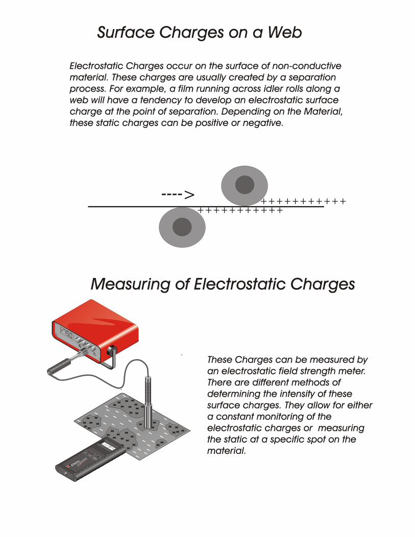
These Charges can be measured by an electrostatic field strength meter. There are different methods of determining the intensity of these surface charges. They allow for either a constant monitoring of the electrostatic charges or measuring the static at a specific spot on the material.
++++++++++++++++++++++
<----
Surface Charges on a Web
Measuring of Electrostatic Charges
HSM 1
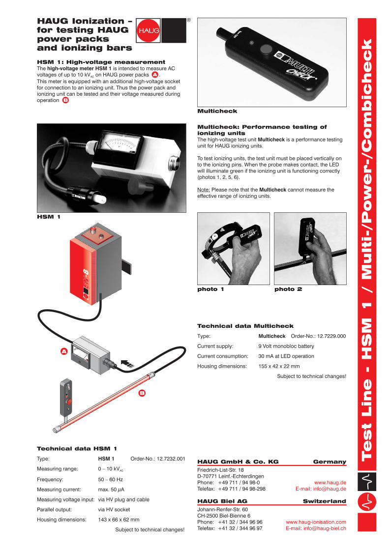
HSM 1: High-voltage measurement
The is intended to measure AC
voltages of up to 10 kV on HAUG power packs .
This meter is equipped with an additional high-voltage socket
for connection to an ionizing unit. Thus the power pack and
ionizing unit can be tested and their voltage measured during
operation .
high-voltage meter HSM 1
AC
Multicheck
Powercheck
Combicheck
Multicheck: Performance testing of
ionizing units
The high-voltage test unit is a performance testing
unit for HAUG ionizing units.
Multicheck
To test ionizing units, the test unit must be placed vertically on
to the ionizing pins. When the probe makes contact, the LED
will illuminate green if the ionizing unit is functioning correctly
(photos 1, 2, 5, 6).
Please note that the cannot measure the
effective range of ionizing units.
Note: Multicheck
Powercheck: Performance testing of
power packs
The high-voltage test unit Powercheck is a performance testing
unit for HAUG power packs.
To test power packs, the black measuring probe with the spring
pin must be inserted into the high-voltage socket of the power
pack (photos 3, 4).
After pressing the red push button, the LED will illuminate green
if the unit is functioning correctly. In case of malfunction, the
LED will illuminate red.
Combicheck: Performance testing of
power packs and ionizing units
The high-voltag test unit is a performance testing
unit for HAUG power packs and HAUG ionizing units.
A selector switch allows the units to be adjusted for the testing
of power packs or ionizing units. In position "Testing of power
packs", the front LED will illuminate, while in position "Testing of
ionizing units" the rear LED will illuminate. To test power packs,
the black measuring probe with the spring pin must be inserted
into the high-voltage socket of the power pack (photos 3, 4).
To test ionizing units, the probe must be held close to the
ionizing pins (photos 1, 2, 5, 6).
Combicheck
Additional information for
Powercheck and Combicheck
The and the are each calibrated as
standard. In the case of the , only the function
"Testing of power packs" is calibrated. The function "Testing of
ionizing units" cannot be calibrated.
To protect the units against ambient humidity, the measuring
probe is protected with a cap in both units.
Powercheck Combicheck
Combicheck
In the event of insufficient battery voltage, the diode does not
light up after the red pushbutton is pressed on the two units
( and ). To change the battery,
remove the battery compartment lid by pushing back the snap-
in tab.
Powercheck Combicheck
Technical data HSM 1
Type: Order-No.: 12.7232.001
Measuring range: 0 – 10 kV
Frequency: 50 – 60 Hz
Measuring current: max. 50 µA
Measuring voltage input: via HV plug and cable
Parallel output: via HV socket
Housing dimensions: 143 x 66 x 62 mm
Subject to technical changes!
HSM 1
AC
Technical data Powercheck
Type: Order-No.: 12.7230.000
with battery compartment,
battery check indicator and
calibration protocol
Current supply: 9 V battery
Current consumption: 15 mA
Housing dimensions: 156 x 40 x 29 mm
Subject to technical changes!
Powercheck
Technical data Combicheck
Type: Order-No.: 12.7231.000
with battery compartment,
battery check indicator and
calibration protocol
Current supply: 9 V battery
Current consumption: 15 mA
Housing dimensions: 156 x 40 x 29 mm
Subject to technical changes!
Combicheck
Technical data Multicheck
Type: Order-No.: 12.7229.000
Current supply: 9 Volt monobloc battery
Current consumption: 30 mA at LED operation
Multicheck
Housing dimensions: 155 x 42 x 22 mm
Subject to technical changes!
A
B
Test Lin
e - H
SM
1 / M
ulti-/Pow
er-/C
om
bic
heck
D-0
07
2-G
B -
03
/08
photo 2
photo 4
photo 6
photo 1
photo 3
photo 5
HAUG Ionization –for testing HAUGpower packsand ionizing bars
V 1.6
A
B
SS
X
YSTEM-2000
MU
LT
I
CH
EC
K
HAUG GmbH & Co. KG Germany
HAUG Biel AG Switzerland
Friedrich-List-Str. 18
D-70771 Leinf.-Echterdingen
Phone: +49 711 / 94 98-0
Telefax: +49 711 / 94 98-298
Johann-Renfer-Str. 60
CH-2500 Biel-Bienne 6
Phone: +41 32 / 344 96 96
Telefax: +41 32 / 344 96 97
www.haug.de
E-mail: [email protected]
www.haug-ionisation.com
E-mail: [email protected]

HSM 1
HSM 1: High-voltage measurement
The is intended to measure AC
voltages of up to 10 kV on HAUG power packs .
This meter is equipped with an additional high-voltage socket
for connection to an ionizing unit. Thus the power pack and
ionizing unit can be tested and their voltage measured during
operation .
high-voltage meter HSM 1
AC
Multicheck
Powercheck
Combicheck
Multicheck: Performance testing of
ionizing units
The high-voltage test unit is a performance testing
unit for HAUG ionizing units.
Multicheck
To test ionizing units, the test unit must be placed vertically on
to the ionizing pins. When the probe makes contact, the LED
will illuminate green if the ionizing unit is functioning correctly
(photos 1, 2, 5, 6).
Please note that the cannot measure the
effective range of ionizing units.
Note: Multicheck
Powercheck: Performance testing of
power packs
The high-voltage test unit Powercheck is a performance testing
unit for HAUG power packs.
To test power packs, the black measuring probe with the spring
pin must be inserted into the high-voltage socket of the power
pack (photos 3, 4).
After pressing the red push button, the LED will illuminate green
if the unit is functioning correctly. In case of malfunction, the
LED will illuminate red.
Combicheck: Performance testing of
power packs and ionizing units
The high-voltag test unit is a performance testing
unit for HAUG power packs and HAUG ionizing units.
A selector switch allows the units to be adjusted for the testing
of power packs or ionizing units. In position "Testing of power
packs", the front LED will illuminate, while in position "Testing of
ionizing units" the rear LED will illuminate. To test power packs,
the black measuring probe with the spring pin must be inserted
into the high-voltage socket of the power pack (photos 3, 4).
To test ionizing units, the probe must be held close to the
ionizing pins (photos 1, 2, 5, 6).
Combicheck
Additional information for
Powercheck and Combicheck
The and the are each calibrated as
standard. In the case of the , only the function
"Testing of power packs" is calibrated. The function "Testing of
ionizing units" cannot be calibrated.
To protect the units against ambient humidity, the measuring
probe is protected with a cap in both units.
Powercheck Combicheck
Combicheck
In the event of insufficient battery voltage, the diode does not
light up after the red pushbutton is pressed on the two units
( and ). To change the battery,
remove the battery compartment lid by pushing back the snap-
in tab.
Powercheck Combicheck
Technical data HSM 1
Type: Order-No.: 12.7232.001
Measuring range: 0 – 10 kV
Frequency: 50 – 60 Hz
Measuring current: max. 50 µA
Measuring voltage input: via HV plug and cable
Parallel output: via HV socket
Housing dimensions: 143 x 66 x 62 mm
Subject to technical changes!
HSM 1
AC
Technical data Powercheck
Type: Order-No.: 12.7230.000
with battery compartment,
battery check indicator and
calibration protocol
Current supply: 9 V battery
Current consumption: 15 mA
Housing dimensions: 156 x 40 x 29 mm
Subject to technical changes!
Powercheck
Technical data Combicheck
Type: Order-No.: 12.7231.000
with battery compartment,
battery check indicator and
calibration protocol
Current supply: 9 V battery
Current consumption: 15 mA
Housing dimensions: 156 x 40 x 29 mm
Subject to technical changes!
Combicheck
Technical data Multicheck
Type: Order-No.: 12.7229.000
Current supply: 9 Volt monobloc battery
Current consumption: 30 mA at LED operation
Multicheck
Housing dimensions: 155 x 42 x 22 mm
Subject to technical changes!
A
B
Test Lin
e - H
SM
1 / M
ulti-/Pow
er-/C
om
bic
heck
D-0
07
2-G
B -
03
/08
photo 2
photo 4
photo 6
photo 1
photo 3
photo 5
HAUG Ionization –for testing HAUGpower packsand ionizing bars
V 1.6
A
B
SS
X
YSTEM-2000
MU
LT
I
CH
EC
K
HAUG GmbH & Co. KG Germany
HAUG Biel AG Switzerland
Friedrich-List-Str. 18
D-70771 Leinf.-Echterdingen
Phone: +49 711 / 94 98-0
Telefax: +49 711 / 94 98-298
Johann-Renfer-Str. 60
CH-2500 Biel-Bienne 6
Phone: +41 32 / 344 96 96
Telefax: +41 32 / 344 96 97
www.haug.de
E-mail: [email protected]
www.haug-ionisation.com
E-mail: [email protected]

Test Lin
e - Perforatio
n counter PZ 3
HAUG Ionization –
for the detection
of perforations
Applications
Mode of operation
Directions for installation
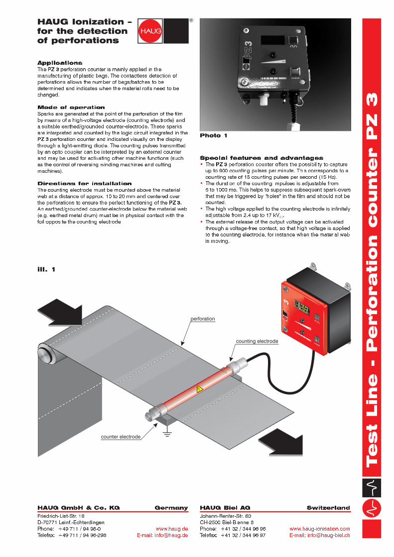
The perforation counter is mainly applied in themanufacturing of plastic bags. The contactless detection ofperforations allows the number of bags/batches to bedetermined and indicates when the material rolls need to bechanged.
Sparks are generated at the point of the perforation of the filmby means of a high-voltage electrode (counting electrode) anda suitable earthed/grounded counter-electrode. These sparksare interpreted and counted by the logic circuit integrated in the
perforation counter and indicated visually on the displaythrough a light-emitting diode. The counting pulses transmittedby an opto-coupler can be interpreted by an external counterand may be used for activating other machine functions (suchas the control of reversing winding machines and cuttingmachines).
The counting electrode must be mounted above the materialweb at a distance of approx. 10 to 20 mm and centered overthe perforations to ensure the perfect functioning of the .An earthed/grounded counter-electrode below the material web(e.g. earthed metal drum) must be in physical contact with thefoil opposite the counting electrode.
PZ 3
PZ 3
PZ 3
Special features and advantagesThe perforation counter offers the possibility to captureup to 900 counting pulses per minute. This corresponds to acounting rate of 15 counting pulses per second (15 Hz).The duration of the counting impulses is adjustable from5 to 1000 ms. This helps to suppress subsequent spark-oversthat may be triggered by "holes" in the film and should not becounted.The high voltage applied to the counting electrode is infinitelyadjustable from 2.4 up to 17 kV .The external release of the output voltage can be activatedthrough a voltage-free contact, so that high voltage is appliedto the counting electrode, for instance when the material webis moving.
PZ 3
DC
�
�
�
�
Photo 1
Ø 20
Effective len
gh
t =
bar
len
gth
- 1
20
mm
Bar
len
gth
= d
ep
en
din
g o
n r
eq
uir
em
en
tC
ab
le len
gth
= 2
00
0 m
m
11
15
N x
15
Ø 20
Ø 25
SX
YS
TEM
-20
00
PZ 3
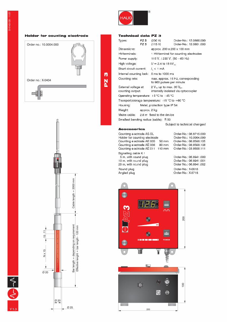
Technical data PZ 3Types: (230 V) Order-No.: 12.0800.000
(115 V) Order-No.: 12.0801.000
HV-terminals: or counting electrodesPower supply: 115 V / 230 V (50 � 60 Hz)High voltage: = 2.4 to 18 kVShort circuit current: < 1 mAInternal counting lock: 5 ms to 1000 msCounting rate: max. approx. 15 Hz, corresponding
to 900 pulses per minute
Operating temperature: +5 °C to +45 °CTransport/storage temperature: -15 °C to +60 °CHousing: Metal, protection type IP 54Weight: approx. 2 kgMains cable:
PZ 3PZ 3
Dimensions: approx. 200 x 200 x 100 mm1 HV-terminal f
External voltage at 2 V up to max. 30 Vcounting output: internally isolated via optocoupler
2.6 m; fixed to the deviceSmallest bending radius (cable): R 50
Subject to technical changes!
Counting electrode AS SL Order-No.: 08.8715.000Holder for counting electrode Order-No.: 10.0004.000Counting electrode AE 005 50 mm Order-No.: 08.8598.105Counting electrode AE 008 80 mm Order-No.: 08.8598.108Counting electrode AE 011 110 mm Order-No.: 08.8598.111Signalling cable K 15 m, with round plug Order-No.: 06.8941.000
10 m, with round plug Order-No.: 06.8941.00120 m, with round plug Order-No.: 06.8941.002Round plug Order-No.: X-0616Angled plug Order-No.: X-5718
~ ~
DC
K
UI
DC DC
Accessories
Holder for counting electrode
Order no.: 10.0004.000
Order no.: X-0404
V 1.3
D-0
14
3-G
B -
11
/07
counter electrode
counting electrode
perforation
HAUG GmbH & Co. KG GermanyFriedrich-List-Str. 18D-70771 Leinf.-EchterdingenPhone: +49 711 / 94 98-0Telefax: +49 711 / 94 98-298
www.haug.deE-mail: [email protected]
HAUG Biel AG SwitzerlandJohann-Renfer-Str. 60CH-2500 Biel-Bienne 6Phone: +41 32 / 344 96 96Telefax: +41 32 / 344 96 97
www.haug-ionisation.comE-mail: [email protected]
10
0
200
20
0
kV
0
I
kV
t POWER
0
I
kVkV
t
PO
WE
R

Test Lin
e - Perforatio
n counter PZ 3
HAUG Ionization –
for the detection
of perforations
Applications
Mode of operation
Directions for installation
The perforation counter is mainly applied in themanufacturing of plastic bags. The contactless detection ofperforations allows the number of bags/batches to bedetermined and indicates when the material rolls need to bechanged.
Sparks are generated at the point of the perforation of the filmby means of a high-voltage electrode (counting electrode) anda suitable earthed/grounded counter-electrode. These sparksare interpreted and counted by the logic circuit integrated in the
perforation counter and indicated visually on the displaythrough a light-emitting diode. The counting pulses transmittedby an opto-coupler can be interpreted by an external counterand may be used for activating other machine functions (suchas the control of reversing winding machines and cuttingmachines).
The counting electrode must be mounted above the materialweb at a distance of approx. 10 to 20 mm and centered overthe perforations to ensure the perfect functioning of the .An earthed/grounded counter-electrode below the material web(e.g. earthed metal drum) must be in physical contact with thefoil opposite the counting electrode.
PZ 3
PZ 3
PZ 3
Special features and advantagesThe perforation counter offers the possibility to captureup to 900 counting pulses per minute. This corresponds to acounting rate of 15 counting pulses per second (15 Hz).The duration of the counting impulses is adjustable from5 to 1000 ms. This helps to suppress subsequent spark-oversthat may be triggered by "holes" in the film and should not becounted.The high voltage applied to the counting electrode is infinitelyadjustable from 2.4 up to 17 kV .The external release of the output voltage can be activatedthrough a voltage-free contact, so that high voltage is appliedto the counting electrode, for instance when the material webis moving.
PZ 3
DC
�
�
�
�
Photo 1
Ø 20
Effective len
gh
t =
bar
len
gth
- 1
20
mm
Bar
len
gth
= d
ep
en
din
g o
n r
eq
uir
em
en
tC
ab
le len
gth
= 2
00
0 m
m
11
15
N x
15
Ø 20
Ø 25
SX
YS
TEM
-20
00
PZ 3
Technical data PZ 3Types: (230 V) Order-No.: 12.0800.000
(115 V) Order-No.: 12.0801.000
HV-terminals: or counting electrodesPower supply: 115 V / 230 V (50 � 60 Hz)High voltage: = 2.4 to 18 kVShort circuit current: < 1 mAInternal counting lock: 5 ms to 1000 msCounting rate: max. approx. 15 Hz, corresponding
to 900 pulses per minute
Operating temperature: +5 °C to +45 °CTransport/storage temperature: -15 °C to +60 °CHousing: Metal, protection type IP 54Weight: approx. 2 kgMains cable:
PZ 3PZ 3
Dimensions: approx. 200 x 200 x 100 mm1 HV-terminal f
External voltage at 2 V up to max. 30 Vcounting output: internally isolated via optocoupler
2.6 m; fixed to the deviceSmallest bending radius (cable): R 50
Subject to technical changes!
Counting electrode AS SL Order-No.: 08.8715.000Holder for counting electrode Order-No.: 10.0004.000Counting electrode AE 005 50 mm Order-No.: 08.8598.105Counting electrode AE 008 80 mm Order-No.: 08.8598.108Counting electrode AE 011 110 mm Order-No.: 08.8598.111Signalling cable K 15 m, with round plug Order-No.: 06.8941.000
10 m, with round plug Order-No.: 06.8941.00120 m, with round plug Order-No.: 06.8941.002Round plug Order-No.: X-0616Angled plug Order-No.: X-5718
~ ~
DC
K
UI
DC DC
Accessories
Holder for counting electrode
Order no.: 10.0004.000
Order no.: X-0404
V 1.3
D-0
14
3-G
B -
11
/07
counter electrode
counting electrode
perforation
HAUG GmbH & Co. KG GermanyFriedrich-List-Str. 18D-70771 Leinf.-EchterdingenPhone: +49 711 / 94 98-0Telefax: +49 711 / 94 98-298
www.haug.deE-mail: [email protected]
HAUG Biel AG SwitzerlandJohann-Renfer-Str. 60CH-2500 Biel-Bienne 6Phone: +41 32 / 344 96 96Telefax: +41 32 / 344 96 97
www.haug-ionisation.comE-mail: [email protected]
10
0
200
20
0
kV
0
I
kV
t POWER
0
I
kVkV
t
PO
WE
R
Statometer II
Static Control
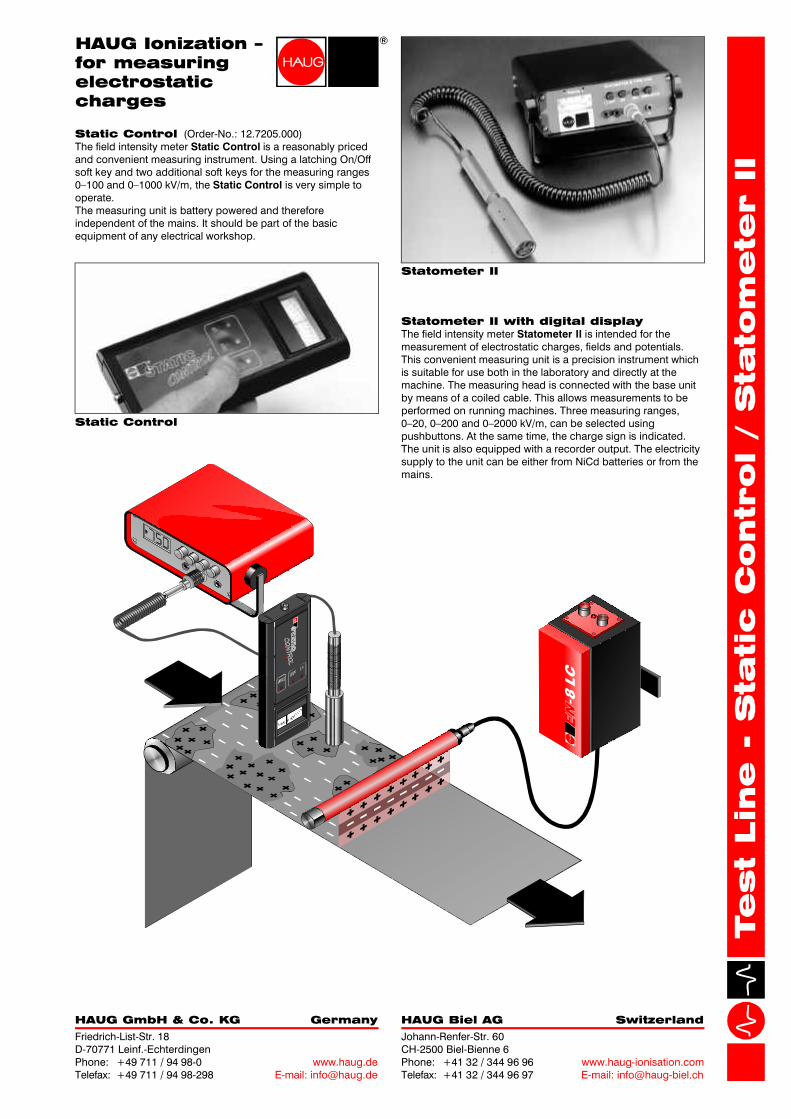
Static Control (Order-No.: 12.7205.000)The field intensity meter is a reasonably pricedand convenient measuring instrument. Using a latching On/Offsoft key and two additional soft keys for the measuring ranges0–100 and 0–1000 kV/m, the is very simple tooperate.The measuring unit is battery powered and thereforeindependent of the mains. It should be part of the basicequipment of any electrical workshop.
Static Control
Static Control
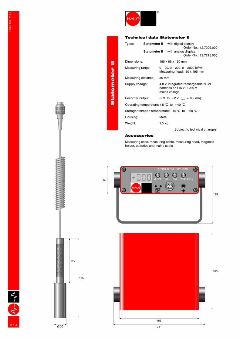
Statometer II with digital displayThe field intensity meter is intended for themeasurement of electrostatic charges, fields and potentials.This convenient measuring unit is a precision instrument whichis suitable for use both in the laboratory and directly at themachine. The measuring head is connected with the base unitby means of a coiled cable. This allows measurements to beperformed on running machines. Three measuring ranges,0–20, 0–200 and 0–2000 kV/m, can be selected usingpushbuttons. At the same time, the charge sign is indicated.The unit is also equipped with a recorder output. The electricitysupply to the unit can be either from NiCd batteries or from themains.
Statometer II
HAUG Ionization –for measuringelectrostaticcharges
HAUG Biel AG Switzerland
Johann-Renfer-Str. 60CH-2500 Biel-Bienne 6Phone: +41 32 / 344 96 96Telefax: +41 32 / 344 96 97
www.haug-ionisation.comE-mail: [email protected]
HAUG GmbH & Co. KG Germany
Friedrich-List-Str. 18D-70771 Leinf.-EchterdingenPhone: +49 711 / 94 98-0Telefax: +49 711 / 94 98-298
www.haug.deE-mail: [email protected]

STATOMETER II TYPE 7209
0 OFF 20 200 2000 kV/m
125
66
185
180
211Ø 30
195
110
V 1.4
Technical data Statometer II
Accessories
Types: with digital displayOrder-No.: 12.7209.000
with analog displayOrder-No.: 12.7215.000
Measuring distance: 30 mm
Supply voltage: 4.8 V, integrated rechargeable NiCdbatteries or 115 V / 230 Vmains voltage
Recorder output: -2 V to +2 V ( = 0,2 mA)
Operating temperature:+5 °C to +40 °C
Storage/transport temperature: -15 °C to +60 °C
Housing: Metal
Weight: 1.5 kg
Subject to technical changes!
Measuring case, measuring cable, measuring head, magneticholder, batteries and mains cable
Statometer II
Statometer II
Dimensions: 185 x 66 x 180 mm
Measuring range: 0 – 20, 0 – 200, 0 – 2000 kV/mMeasuring head: 30 x 195 mm
~ ~
maxI

Measuring electrostatic chargesElectrostatic charges always occur where highly insulatingmaterials, such as most plastics, are used. The resulting fieldpatterns, such as and , are easy to be evaluatedtheoretically, but they are of minor interest to the practician. Forthe latter it is important to know the level of these electrostaticcharges and the spot in the machine of facility where theyoccur. Therefore he should have specific devices at his disposalto measure these interfering charges.
measures electrostatic charges according tothe fieldmill influence principle : The influenced charges,caused by electrically field, generate an alternating currentproportional to the electrical field strength. The selectiveamplifier converts this value into the corresponding fieldstrength or electrical potential – without withdrawing energyfrom the electric field over the averaged time.
Static Meter IThe recently developed electrofieldmeter is asmall hand-held field strength meter with digital display formeasuring electrostatic charges in Volt. It perfectly combineseasy operation with accurate measuring technique.The
Static Meter
Static Meter
I
I
Applications
Special features and advantages
Accessories
The use of the can be a precautionary measurein all manufacturing processes, where electrostatic chargesmay occur. However, this device is not approved for use inhazardous locations!
Variable measuring distance:In order to obtain optimum results, the distance between testobject and sensor head – depending on the degree ofcharge and the condition of the object's surface – can beselected incrementally.Hold function:The device is equipped with a Hold function to keep themeasured value stored on the display.Display in V:The integrated micro-computer automatically converts themeasured field strength into the equivalent charge in V.
Two 26 mm long spaces are supplied together with the device.These ensure that the distance of measurement is alwayscorrect (= 2 cm).
Static Meter I
•
•
•
HAUG Ionization –for measuringelectrostaticcharges
Mode of operationField pattern of an uniformly charged film and of a uniformlycharged film above an earthed/grounded metal plate .
The electric field of the electrostatic charge is converted into ameasuring alternating current through the cyclical covering ofthe sensor plates. The display shows a tension proportional tothe intensity and polarity of the field to be measured.Field strength meters that are working according to this priciplehave a high measuring sensitivity and allow very accuratemeasuring.
Static Meter I
film
electrical field = ––σ QA
film
earthed/groundedmetal plate
electrical field = ––σ QA
covering platepair of sensor plates
motor
amplifier
display
electrical field
= ––σ QA
ill. 1
film
HAUG GmbH & Co. KG Germany
HAUG Biel AG Switzerland
Friedrich-List-Str. 18D-70771 Leinf.-EchterdingenPhone: +49 711 / 94 98-0Telefax: +49 711 / 94 98-298
Johann-Renfer-Str. 60CH-2500 Biel-Bienne 6Phone: +41 32 / 344 96 96Telefax: +41 32 / 344 96 97
www.haug.deE-mail: [email protected]
www.haug-ionisation.comE-mail: [email protected]

25
26
V 1.2
116
Technical data Static Meter I
Type: Order-No: 12.7210.000
Power supply: 9 V - alkaline batteryIEC 6F22 or 9 V NiCd or NiMH accu
Measuring ranges: Distance 1 cm:0 .. 10 kV, max. resolution 1 VDistance 2 cm:0 .. 20 kV, max. resolution 2 VDistance 5 cm:0 .. 50 kV, max. resolution 10 VDistance 10 cm:0 .. 100 kV,Distance 20 cm:0 .. 200 kV, max. resolution 20 V
Display: alphanumeric LCD-display, two lineswith 12 digits each
Operating time: approx. 10 hours in continious duty
Balancing: within the homogeneous field of a platecapacitors, measuring device built in thecenter of the pasted plateplate size 100 mm x 100 mm,distance between plates 20 mm
Subject to technical changes!
Static Meter I
max. resolution 10 V
Operating temperature: +5 °C to +50 °C
Storage/transport temperature: -15 °C to +60 °C
Weight: 130 g (without battery)

HSM 1
HSM 1: High-voltage measurement
The is intended to measure AC
voltages of up to 10 kV on HAUG power packs .
This meter is equipped with an additional high-voltage socket
for connection to an ionizing unit. Thus the power pack and
ionizing unit can be tested and their voltage measured during
operation .
high-voltage meter HSM 1
AC
Multicheck
Powercheck
Combicheck
Multicheck: Performance testing of
ionizing units
The high-voltage test unit is a performance testing
unit for HAUG ionizing units.
Multicheck
To test ionizing units, the test unit must be placed vertically on
to the ionizing pins. When the probe makes contact, the LED
will illuminate green if the ionizing unit is functioning correctly
(photos 1, 2, 5, 6).
Please note that the cannot measure the
effective range of ionizing units.
Note: Multicheck
Powercheck: Performance testing of
power packs
The high-voltage test unit Powercheck is a performance testing
unit for HAUG power packs.
To test power packs, the black measuring probe with the spring
pin must be inserted into the high-voltage socket of the power
pack (photos 3, 4).
After pressing the red push button, the LED will illuminate green
if the unit is functioning correctly. In case of malfunction, the
LED will illuminate red.
Combicheck: Performance testing of
power packs and ionizing units
The high-voltag test unit is a performance testing
unit for HAUG power packs and HAUG ionizing units.
A selector switch allows the units to be adjusted for the testing
of power packs or ionizing units. In position "Testing of power
packs", the front LED will illuminate, while in position "Testing of
ionizing units" the rear LED will illuminate. To test power packs,
the black measuring probe with the spring pin must be inserted
into the high-voltage socket of the power pack (photos 3, 4).
To test ionizing units, the probe must be held close to the
ionizing pins (photos 1, 2, 5, 6).
Combicheck
Additional information for
Powercheck and Combicheck
The and the are each calibrated as
standard. In the case of the , only the function
"Testing of power packs" is calibrated. The function "Testing of
ionizing units" cannot be calibrated.
To protect the units against ambient humidity, the measuring
probe is protected with a cap in both units.
Powercheck Combicheck
Combicheck
In the event of insufficient battery voltage, the diode does not
light up after the red pushbutton is pressed on the two units
( and ). To change the battery,
remove the battery compartment lid by pushing back the snap-
in tab.
Powercheck Combicheck
Technical data HSM 1
Type: Order-No.: 12.7232.001
Measuring range: 0 – 10 kV
Frequency: 50 – 60 Hz
Measuring current: max. 50 µA
Measuring voltage input: via HV plug and cable
Parallel output: via HV socket
Housing dimensions: 143 x 66 x 62 mm
Subject to technical changes!
HSM 1
AC
Technical data Powercheck
Type: Order-No.: 12.7230.000
with battery compartment,
battery check indicator and
calibration protocol
Current supply: 9 V battery
Current consumption: 15 mA
Housing dimensions: 156 x 40 x 29 mm
Subject to technical changes!
Powercheck
Technical data Combicheck
Type: Order-No.: 12.7231.000
with battery compartment,
battery check indicator and
calibration protocol
Current supply: 9 V battery
Current consumption: 15 mA
Housing dimensions: 156 x 40 x 29 mm
Subject to technical changes!
Combicheck
Technical data Multicheck
Type: Order-No.: 12.7229.000
Current supply: 9 Volt monobloc battery
Current consumption: 30 mA at LED operation
Multicheck
Housing dimensions: 155 x 42 x 22 mm
Subject to technical changes!
A
B
Test Lin
e - H
SM
1 / M
ulti-/Pow
er-/C
om
bic
heck
D-0
07
2-G
B -
03
/08
photo 2
photo 4
photo 6
photo 1
photo 3
photo 5
HAUG Ionization –for testing HAUGpower packsand ionizing bars
V 1.6
A
B
SS
X
YSTEM-2000
MU
LT
I
CH
EC
K
HAUG GmbH & Co. KG Germany
HAUG Biel AG Switzerland
Friedrich-List-Str. 18
D-70771 Leinf.-Echterdingen
Phone: +49 711 / 94 98-0
Telefax: +49 711 / 94 98-298
Johann-Renfer-Str. 60
CH-2500 Biel-Bienne 6
Phone: +41 32 / 344 96 96
Telefax: +41 32 / 344 96 97
www.haug.de
E-mail: [email protected]
www.haug-ionisation.com
E-mail: [email protected]

HSM 1
HSM 1: High-voltage measurement
The is intended to measure AC
voltages of up to 10 kV on HAUG power packs .
This meter is equipped with an additional high-voltage socket
for connection to an ionizing unit. Thus the power pack and
ionizing unit can be tested and their voltage measured during
operation .
high-voltage meter HSM 1
AC
Multicheck
Powercheck
Combicheck
Multicheck: Performance testing of
ionizing units
The high-voltage test unit is a performance testing
unit for HAUG ionizing units.
Multicheck
To test ionizing units, the test unit must be placed vertically on
to the ionizing pins. When the probe makes contact, the LED
will illuminate green if the ionizing unit is functioning correctly
(photos 1, 2, 5, 6).
Please note that the cannot measure the
effective range of ionizing units.
Note: Multicheck
Powercheck: Performance testing of
power packs
The high-voltage test unit Powercheck is a performance testing
unit for HAUG power packs.
To test power packs, the black measuring probe with the spring
pin must be inserted into the high-voltage socket of the power
pack (photos 3, 4).
After pressing the red push button, the LED will illuminate green
if the unit is functioning correctly. In case of malfunction, the
LED will illuminate red.
Combicheck: Performance testing of
power packs and ionizing units
The high-voltag test unit is a performance testing
unit for HAUG power packs and HAUG ionizing units.
A selector switch allows the units to be adjusted for the testing
of power packs or ionizing units. In position "Testing of power
packs", the front LED will illuminate, while in position "Testing of
ionizing units" the rear LED will illuminate. To test power packs,
the black measuring probe with the spring pin must be inserted
into the high-voltage socket of the power pack (photos 3, 4).
To test ionizing units, the probe must be held close to the
ionizing pins (photos 1, 2, 5, 6).
Combicheck
Additional information for
Powercheck and Combicheck
The and the are each calibrated as
standard. In the case of the , only the function
"Testing of power packs" is calibrated. The function "Testing of
ionizing units" cannot be calibrated.
To protect the units against ambient humidity, the measuring
probe is protected with a cap in both units.
Powercheck Combicheck
Combicheck
In the event of insufficient battery voltage, the diode does not
light up after the red pushbutton is pressed on the two units
( and ). To change the battery,
remove the battery compartment lid by pushing back the snap-
in tab.
Powercheck Combicheck
Technical data HSM 1
Type: Order-No.: 12.7232.001
Measuring range: 0 – 10 kV
Frequency: 50 – 60 Hz
Measuring current: max. 50 µA
Measuring voltage input: via HV plug and cable
Parallel output: via HV socket
Housing dimensions: 143 x 66 x 62 mm
Subject to technical changes!
HSM 1
AC
Technical data Powercheck
Type: Order-No.: 12.7230.000
with battery compartment,
battery check indicator and
calibration protocol
Current supply: 9 V battery
Current consumption: 15 mA
Housing dimensions: 156 x 40 x 29 mm
Subject to technical changes!
Powercheck
Technical data Combicheck
Type: Order-No.: 12.7231.000
with battery compartment,
battery check indicator and
calibration protocol
Current supply: 9 V battery
Current consumption: 15 mA
Housing dimensions: 156 x 40 x 29 mm
Subject to technical changes!
Combicheck
Technical data Multicheck
Type: Order-No.: 12.7229.000
Current supply: 9 Volt monobloc battery
Current consumption: 30 mA at LED operation
Multicheck
Housing dimensions: 155 x 42 x 22 mm
Subject to technical changes!
A
B
Test Lin
e - H
SM
1 / M
ulti-/Pow
er-/C
om
bic
heck
D-0
07
2-G
B -
03
/08
photo 2
photo 4
photo 6
photo 1
photo 3
photo 5
HAUG Ionization –for testing HAUGpower packsand ionizing bars
V 1.6
A
B
SS
X
YSTEM-2000
MU
LT
I
CH
EC
K
HAUG GmbH & Co. KG Germany
HAUG Biel AG Switzerland
Friedrich-List-Str. 18
D-70771 Leinf.-Echterdingen
Phone: +49 711 / 94 98-0
Telefax: +49 711 / 94 98-298
Johann-Renfer-Str. 60
CH-2500 Biel-Bienne 6
Phone: +41 32 / 344 96 96
Telefax: +41 32 / 344 96 97
www.haug.de
E-mail: [email protected]
www.haug-ionisation.com
E-mail: [email protected]
Test Lin
e - Perforatio
n counter PZ 3
HAUG Ionization –
for the detection
of perforations
Applications
Mode of operation
Directions for installation
The perforation counter is mainly applied in themanufacturing of plastic bags. The contactless detection ofperforations allows the number of bags/batches to bedetermined and indicates when the material rolls need to bechanged.
Sparks are generated at the point of the perforation of the filmby means of a high-voltage electrode (counting electrode) anda suitable earthed/grounded counter-electrode. These sparksare interpreted and counted by the logic circuit integrated in the
perforation counter and indicated visually on the displaythrough a light-emitting diode. The counting pulses transmittedby an opto-coupler can be interpreted by an external counterand may be used for activating other machine functions (suchas the control of reversing winding machines and cuttingmachines).
The counting electrode must be mounted above the materialweb at a distance of approx. 10 to 20 mm and centered overthe perforations to ensure the perfect functioning of the .An earthed/grounded counter-electrode below the material web(e.g. earthed metal drum) must be in physical contact with thefoil opposite the counting electrode.
PZ 3
PZ 3
PZ 3
Special features and advantagesThe perforation counter offers the possibility to captureup to 900 counting pulses per minute. This corresponds to acounting rate of 15 counting pulses per second (15 Hz).The duration of the counting impulses is adjustable from5 to 1000 ms. This helps to suppress subsequent spark-oversthat may be triggered by "holes" in the film and should not becounted.The high voltage applied to the counting electrode is infinitelyadjustable from 2.4 up to 17 kV .The external release of the output voltage can be activatedthrough a voltage-free contact, so that high voltage is appliedto the counting electrode, for instance when the material webis moving.
PZ 3
DC
�
�
�
�
Photo 1
Ø 20
Effective len
gh
t =
bar
len
gth
- 1
20
mm
Bar
len
gth
= d
ep
en
din
g o
n r
eq
uir
em
en
tC
ab
le len
gth
= 2
00
0 m
m
11
15
N x
15
Ø 20
Ø 25
SX
YS
TEM
-20
00
PZ 3
Technical data PZ 3Types: (230 V) Order-No.: 12.0800.000
(115 V) Order-No.: 12.0801.000
HV-terminals: or counting electrodesPower supply: 115 V / 230 V (50 � 60 Hz)High voltage: = 2.4 to 18 kVShort circuit current: < 1 mAInternal counting lock: 5 ms to 1000 msCounting rate: max. approx. 15 Hz, corresponding
to 900 pulses per minute
Operating temperature: +5 °C to +45 °CTransport/storage temperature: -15 °C to +60 °CHousing: Metal, protection type IP 54Weight: approx. 2 kgMains cable:
PZ 3PZ 3
Dimensions: approx. 200 x 200 x 100 mm1 HV-terminal f
External voltage at 2 V up to max. 30 Vcounting output: internally isolated via optocoupler
2.6 m; fixed to the deviceSmallest bending radius (cable): R 50
Subject to technical changes!
Counting electrode AS SL Order-No.: 08.8715.000Holder for counting electrode Order-No.: 10.0004.000Counting electrode AE 005 50 mm Order-No.: 08.8598.105Counting electrode AE 008 80 mm Order-No.: 08.8598.108Counting electrode AE 011 110 mm Order-No.: 08.8598.111Signalling cable K 15 m, with round plug Order-No.: 06.8941.000
10 m, with round plug Order-No.: 06.8941.00120 m, with round plug Order-No.: 06.8941.002Round plug Order-No.: X-0616Angled plug Order-No.: X-5718
~ ~
DC
K
UI
DC DC
Accessories
Holder for counting electrode
Order no.: 10.0004.000
Order no.: X-0404
V 1.3
D-0
14
3-G
B -
11
/07
counter electrode
counting electrode
perforation
HAUG GmbH & Co. KG GermanyFriedrich-List-Str. 18D-70771 Leinf.-EchterdingenPhone: +49 711 / 94 98-0Telefax: +49 711 / 94 98-298
www.haug.deE-mail: [email protected]
HAUG Biel AG SwitzerlandJohann-Renfer-Str. 60CH-2500 Biel-Bienne 6Phone: +41 32 / 344 96 96Telefax: +41 32 / 344 96 97
www.haug-ionisation.comE-mail: [email protected]
10
0
200
20
0
kV
0
I
kV
t POWER
0
I
kVkV
t
PO
WE
R

Statometer II
Static Control
Static Control (Order-No.: 12.7205.000)The field intensity meter is a reasonably pricedand convenient measuring instrument. Using a latching On/Offsoft key and two additional soft keys for the measuring ranges0–100 and 0–1000 kV/m, the is very simple tooperate.The measuring unit is battery powered and thereforeindependent of the mains. It should be part of the basicequipment of any electrical workshop.
Static Control
Static Control
Statometer II with digital displayThe field intensity meter is intended for themeasurement of electrostatic charges, fields and potentials.This convenient measuring unit is a precision instrument whichis suitable for use both in the laboratory and directly at themachine. The measuring head is connected with the base unitby means of a coiled cable. This allows measurements to beperformed on running machines. Three measuring ranges,0–20, 0–200 and 0–2000 kV/m, can be selected usingpushbuttons. At the same time, the charge sign is indicated.The unit is also equipped with a recorder output. The electricitysupply to the unit can be either from NiCd batteries or from themains.
Statometer II
HAUG Ionization –for measuringelectrostaticcharges
HAUG Biel AG Switzerland
Johann-Renfer-Str. 60CH-2500 Biel-Bienne 6Phone: +41 32 / 344 96 96Telefax: +41 32 / 344 96 97
www.haug-ionisation.comE-mail: [email protected]
HAUG GmbH & Co. KG Germany
Friedrich-List-Str. 18D-70771 Leinf.-EchterdingenPhone: +49 711 / 94 98-0Telefax: +49 711 / 94 98-298
www.haug.deE-mail: [email protected]
STATOMETER II TYPE 7209
0 OFF 20 200 2000 kV/m
125
66
185
180
211Ø 30
195
110
V 1.4
Technical data Statometer II
Accessories
Types: with digital displayOrder-No.: 12.7209.000
with analog displayOrder-No.: 12.7215.000
Measuring distance: 30 mm
Supply voltage: 4.8 V, integrated rechargeable NiCdbatteries or 115 V / 230 Vmains voltage
Recorder output: -2 V to +2 V ( = 0,2 mA)
Operating temperature:+5 °C to +40 °C
Storage/transport temperature: -15 °C to +60 °C
Housing: Metal
Weight: 1.5 kg
Subject to technical changes!
Measuring case, measuring cable, measuring head, magneticholder, batteries and mains cable
Statometer II
Statometer II
Dimensions: 185 x 66 x 180 mm
Measuring range: 0 – 20, 0 – 200, 0 – 2000 kV/mMeasuring head: 30 x 195 mm
~ ~
maxI

Measuring electrostatic chargesElectrostatic charges always occur where highly insulatingmaterials, such as most plastics, are used. The resulting fieldpatterns, such as and , are easy to be evaluatedtheoretically, but they are of minor interest to the practician. Forthe latter it is important to know the level of these electrostaticcharges and the spot in the machine of facility where theyoccur. Therefore he should have specific devices at his disposalto measure these interfering charges.
measures electrostatic charges according tothe fieldmill influence principle : The influenced charges,caused by electrically field, generate an alternating currentproportional to the electrical field strength. The selectiveamplifier converts this value into the corresponding fieldstrength or electrical potential – without withdrawing energyfrom the electric field over the averaged time.
Static Meter IThe recently developed electrofieldmeter is asmall hand-held field strength meter with digital display formeasuring electrostatic charges in Volt. It perfectly combineseasy operation with accurate measuring technique.The
Static Meter
Static Meter
I
I
Applications
Special features and advantages
Accessories
The use of the can be a precautionary measurein all manufacturing processes, where electrostatic chargesmay occur. However, this device is not approved for use inhazardous locations!
Variable measuring distance:In order to obtain optimum results, the distance between testobject and sensor head – depending on the degree ofcharge and the condition of the object's surface – can beselected incrementally.Hold function:The device is equipped with a Hold function to keep themeasured value stored on the display.Display in V:The integrated micro-computer automatically converts themeasured field strength into the equivalent charge in V.
Two 26 mm long spaces are supplied together with the device.These ensure that the distance of measurement is alwayscorrect (= 2 cm).
Static Meter I
•
•
•
HAUG Ionization –for measuringelectrostaticcharges
Mode of operationField pattern of an uniformly charged film and of a uniformlycharged film above an earthed/grounded metal plate .
The electric field of the electrostatic charge is converted into ameasuring alternating current through the cyclical covering ofthe sensor plates. The display shows a tension proportional tothe intensity and polarity of the field to be measured.Field strength meters that are working according to this priciplehave a high measuring sensitivity and allow very accuratemeasuring.
Static Meter I
film
electrical field = ––σ QA
film
earthed/groundedmetal plate
electrical field = ––σ QA
covering platepair of sensor plates
motor
amplifier
display
electrical field
= ––σ QA
ill. 1
film
HAUG GmbH & Co. KG Germany
HAUG Biel AG Switzerland
Friedrich-List-Str. 18D-70771 Leinf.-EchterdingenPhone: +49 711 / 94 98-0Telefax: +49 711 / 94 98-298
Johann-Renfer-Str. 60CH-2500 Biel-Bienne 6Phone: +41 32 / 344 96 96Telefax: +41 32 / 344 96 97
www.haug.deE-mail: [email protected]
www.haug-ionisation.comE-mail: [email protected]

25
26
V 1.2
116
Technical data Static Meter I
Type: Order-No: 12.7210.000
Power supply: 9 V - alkaline batteryIEC 6F22 or 9 V NiCd or NiMH accu
Measuring ranges: Distance 1 cm:0 .. 10 kV, max. resolution 1 VDistance 2 cm:0 .. 20 kV, max. resolution 2 VDistance 5 cm:0 .. 50 kV, max. resolution 10 VDistance 10 cm:0 .. 100 kV,Distance 20 cm:0 .. 200 kV, max. resolution 20 V
Display: alphanumeric LCD-display, two lineswith 12 digits each
Operating time: approx. 10 hours in continious duty
Balancing: within the homogeneous field of a platecapacitors, measuring device built in thecenter of the pasted plateplate size 100 mm x 100 mm,distance between plates 20 mm
Subject to technical changes!
Static Meter I
max. resolution 10 V
Operating temperature: +5 °C to +50 °C
Storage/transport temperature: -15 °C to +60 °C
Weight: 130 g (without battery)

Field intensity meter Statometer III
The HAUG field intensity meter is a consistent
further development of the previous field intensity meter
Statometer II. It is intended for the measurement of electrostatic
and slow alternating fields.
With its new, patented measuring process, electric fields from
approx. 0.2 kV/m and low-frequency alternating fields up to
approx. 20 Hz can be measured. Due to the use of high-grade,
wear-free components, the can also be used in
continuous operation.
Statometer III
Statometer III
Special properties and benefits
Properties of the evaluation software
Due to the geometry of the measuring head, very low field
intensities can be measured. The calibrated measuring distance
of the measuring head to the measured surface is 30 mm. The
measuring head is connected to the display unit via a coiled
cable. The has three measuring ranges which
are switched over automatically during measurement. No
manual switchover is therefore required.
The field intensity meter can be operated both from the mains
and with commercially available NiMH rechargeable batteries.
An integrated automatic switch-off function protects the
batteries from exhaustive discharge.
Using the supplied optical connection cable, the
can be connected to a PC's serial port in a floating connection.
The supplied software allows the large display of the current
measuring value or the performance of short-term and long-
term measurements over several days.
The measured values can be displayed graphically and
exported, e.g. for further processing in measuring and
analytical programs. Variable zooms are possible.
The measured data can be saved to hard disk and archived.
Statometer III
Statometer III
Applications
The HAUG can be used for the measurement of
electric fields or electrostatic charges both in the laboratory
and in production machinery.
Statometer III
Test Lin
e–
Sta
tom
ete
r III
HAUG Ionization –
for measuring
electrostatic
charges
Statometer III
ill. 1
®
STATOM
ETER
Error
Charge
ON
OFF
Output
kV/mkBaud
19.2
4.89.6
Accumulator
HAUG GmbH & Co. KG Germany
HAUG Biel AG Switzerland
Friedrich-List-Str. 18
D-70771 Leinf.-Echterdingen
Phone: +49 711 / 94 98-0
Telefax: +49 711 / 94 98-298
Johann-Renfer-Str. 60
CH-2500 Biel-Bienne 6
Phone: +41 32 / 344 96 96
Telefax: +41 32 / 344 96 97
www.haug.de
E-mail: [email protected]
www.haug-ionisation.com
E-mail: [email protected]

V 1.6
D-0
13
2-G
B -
06
/09
Sta
tom
ete
r III
180
85
~ 1
00
245
®
STATOMETER
ErrorCharge
ON
OFF
Output
kV/m
kBaud
19.2
4.89.6
Accumulator
60
10
0
16
9
Technical data Statometer III
Accessories
Type: Order-No.: 12.7216.000
Protection type: IP 20
Supply voltage: 230 V (50 – 60 Hz)
Battery operation: 5 x NiMH rechargeable batteries,
type AA (round cell)
Measuring range: 0 – 20 kV/m
0 – 200 kV/m
0 – 2000 kV/m
Resolution: 0,2 kV/m
Measuring distance: 30 mm
Output voltage: ±10 V
Accuracy: ±10 %
Cut-off frequency for alternating fields: 20 Hz
Display: 3 ½-digit liquid-cristal display
Recorder output: -10 V to +10 V, analog
Transfer rate: 4800 / 9600 / 19200 Baud
Operating temperature: +5 °C to +40 °C
Storage/transport temperature: -15 °C to +60 °C
Dimensions Statometer III: 85 x 245 x 180 mm (H/W/D)
Dimensions measuring head: 169 x Ø 60 mm
Weight: 2,4 kg
Housing: Metal
Subject to technical changes!
(included in delivery)
Included in delivery: Measuring case, display unit, measuring
head, magnetic holder, batteries, mains cable and optical serial
cable (2 x 35-pin), software on CD
Optional:
USB adapter for serial interface Order-No.: X-7600
Statometer III
AC