
SUPPLY and INSTALL 15MVA 11kV/33kV … ELECTRICITY AUTHORITY TENDER DOCUMENT SUPPLY and INSTALL...
149
FIJI ELECTRICITY AUTHORITY TENDER DOCUMENT SUPPLY and INSTALL 15MVA 11kV/33kV GENERATING TRANSFORMER AT NEW Vuda POWER STATION TENDER NO: MR 238/2017
Transcript of SUPPLY and INSTALL 15MVA 11kV/33kV … ELECTRICITY AUTHORITY TENDER DOCUMENT SUPPLY and INSTALL...
FIJI ELECTRICITY AUTHORITY TENDER DOCUMENT
SUPPLY and INSTALL 15MVA 11kV/33kV
GENERATING TRANSFORMER AT NEW Vuda POWER STATION
TENDER NO: MR 238/2017

Supply and Installation of TWO 11kV/33kV New Vuda PS Generating Transformers
Bidding Document
ii
Invitation for Bids Date : 23rd Sept, 2017 Tender No : MR 238/2017 The Fiji Electricity Authority ("the Employer") invites sealed bids from reputable transformer manufacturer companies for the design, manufacture, supply, transport, install and commission two (2) units 11kV/33kV, 15MVA Generating transformer at its New Vuda Power Station. The Tenderer is required to submit a bid for: The complete design, manufacture, testing, shipping, transportation to site, installation and commissioning of a 15MVA, 11kV/33kV, YNd1, 50Hz, ONAN Generating transformer with off-load tap changer at New Vuda Power Station. All tenders for the contract shall be submitted on the appropriate tender forms provided and shall include the completed guarantees, price schedule, technical schedule and schedules of experience etc. relevant copies of which are included. The tender shall be on the basis of a lump sum contract based on firm prices. Bidders may obtain further information from, inspect and acquire the bidding documents and, if required, arrange for a site visit from
Tuvitu Delairewa General Manager Corporate Services 2 Marlow Street, Suva, FIJI. Phone: 679 3224 185 Facsimile: 679 331 1882 Email: [email protected]
Site visit at new Vuda Power Station with FEA representatives will be at 11am Tuesday, 3rd October, 2017. Deadline for submission of tenders shall be 1600 hours local Fiji Time on Wednesday, 25th October, 2017 During evaluation of tenders the Authority will invite a tenderer or tenderers for discussions, presentations and any necessary clarification before awarding of the contract.
Supply and Installation of TWO 11kV/33kV New Vuda PS Generating Transformers
Bidding Document
ii
TABLE OF CONTENTS
INVITATION FOR BIDS ...................................................................................................................................... II
SECTION 1 INSTRUCTION TO BIDDERS ............................................................................................................. 6
SECTION 2 GENERAL CONDITIONS OF CONTRACT .......................................................................................... 21
SECTION 3 CONDITIONS OF PARTICULAR APPLICATION ................................................................................. 22
SECTION 4 EMPLOYER’S REQUIREMENTS – .................................................................................................... 31
PART I ............................................................................................................................................................ 31
SCOPE OF WORKS .......................................................................................................................................... 31
1 GENERAL DESCRIPTION .......................................................................................................................... 32 1.1 Background ........................................................................................................................................ 32 1.2 Extent of Work ................................................................................................................................... 32 1.3 Supply of New Generation Transformer at New Vuda Power Station ............................................... 33 1.4 Electricity and Water ......................................................................................................................... 33 1.5 Civil Works ......................................................................................................................................... 34 1.6 Cable and Overhead Line Terminations ............................................................................................. 34 1.7 Training .............................................................................................................................................. 34 1.8 Objective of Training Modules ........................................................................................................... 34
SECTION 4 EMPLOYER’S REQUIREMENTS - PART II TECHNICAL SPECIFICATIONS ............................................ 35
1. GENERAL INFORMATION ........................................................................................................................ 36 1.1 ASSOCIATED PLANT DETAILS ............................................................................................................. 36 1.2 ELECTRICAL DESIGN CRITERIA ............................................................................................................ 36 1.2.1 System Conditions ......................................................................................................................... 36 1.2.2 Service Conditions ......................................................................................................................... 36 1.2.3 Power supply for electrical operation ........................................................................................... 36 1.2.4 Minimum Substation Clearances .................................................................................................. 37 1.2.5 Pollution levels of Insulators and Bushings ................................................................................... 37 1.2.6 Insulation Co-ordination ............................................................................................................... 37 1.2.7 Inter-Changeability ....................................................................................................................... 37 1.2.8 Maintainability.............................................................................................................................. 37 1.2.9 Ventilation .................................................................................................................................... 37 1.2.10 Risk of Fire ................................................................................................................................ 37 1.3 QUALITY OF MATERIALS AND WORKMANSHIP ................................................................................. 37 1.4 STANDARDS ....................................................................................................................................... 38 1.5 DETAILED DESIGN OF PLANT AND EQUIPMENT ................................................................................ 38 1.6 PLANT AND EQUIPMENT TO BE SUPPLIED ........................................................................................ 38 1.7 INSPECTION AND TESTING ................................................................................................................. 38 1.8 TRAINING OF FEA PERSONNEL .......................................................................................................... 39 1.9 TOOLS AND EQUIPMENT ................................................................................................................... 39 1.10 SPARES .......................................................................................................................................... 39 1.11 TECHNICAL LITERATURE - OPERATIONS AND MAINTENANCE MANUALS ..................................... 40 1.11.1 Plant Specification and Description .......................................................................................... 40 1.11.2 Installation and Commissioning ............................................................................................... 40 1.11.3 Operation ................................................................................................................................. 40 1.12 Maintenance ................................................................................................................................. 40 1.13 TYPE TEST CERTIFICATES ............................................................................................................... 41 1.14 SITE CONDITIONS .......................................................................................................................... 41 1.15 PACKING ........................................................................................................................................ 41 1.16 PROGRAMME AND PROGRESS OF WORK ..................................................................................... 42
2. SECONDARY WIRING AND ANCILLARY ELECTRICAL APPARATUS ............................................................ 43
Supply and Installation of TWO 11kV/33kV New Vuda PS Generating Transformers
Bidding Document
iii
2.1 SECONDARY WIRING ......................................................................................................................... 43 2.2 TERMINAL BOARDS ............................................................................................................................ 44 2.3 TERMINALS ........................................................................................................................................ 45 2.4 CONTROL SWITCHES AND PUSHBUTTONS ........................................................................................ 45 2.5 ELECTRICAL MOTORS ......................................................................................................................... 46 2.6 INDICATING LAMPS AND FITTINGS – EUROPEAN ISKRA .................................................................... 47 2.7 STARTERS AND CONTACTORS ............................................................................................................ 47 2.8 JUNCTION, TERMINAL BOXES AND TRANSFORMER CUBICLES .......................................................... 47 2.9 TRANSFORMER MARSHALLING KIOSKS ............................................................................................. 48 2.10 GAUGE CUBICLES AND PANELS ..................................................................................................... 49 2.11 ANTI-CONDENSATION HEATERS ................................................................................................... 49 2.12 INTERIOR LIGHTS........................................................................................................................... 49 2.13 CABLES AND CABLE LADDERS ....................................................................................................... 50 2.14 LABELS ........................................................................................................................................... 50
3. PROTECTION, METERING AND CONTROL ............................................................................................... 51 3.1 TRANSFORMER PROTECTION ............................................................................................................ 51
4. TRANSFORMER ....................................................................................................................................... 58 4.1 TYPE OF TRANSFORMER AND OPERATING CONDITIONS .................................................................. 58 4.2 RATING AND OPERATION .................................................................................................................. 58 4.3 TRANSFORMER CORE ........................................................................................................................ 60 4.4 WINDING ........................................................................................................................................... 60 4.5 COOLING ............................................................................................................................................ 62 4.6 CONTINUOUS MAXIMUM RATING .................................................................................................... 62 4.7 ELECTRICAL CONNECTION ................................................................................................................. 62 4.8 ABILITY TO WITHSTAND SHORT CIRCUIT ........................................................................................... 62 4.9 Service Conditions .............................................................................................................................. 64 4.10 NOISE ............................................................................................................................................ 64 4.11 Audible Sound Level ...................................................................................................................... 64 4.12 CORONA INCEPTION FIELDS .......................................................................................................... 64 4.13 HARMONIC SUPPRESSION ............................................................................................................ 64 4.14 MAGNETIC CIRCUIT AND WINDINGS ............................................................................................ 65 4.15 WINDING CONNECTIONS .............................................................................................................. 65 4.16 THERMAL AND MOISTURE MONITORING ..................................................................................... 65 4.17 FIBRE OPTIC TEMPERATURE PROBES ............................................................................................ 66 4.18 Fibre Optic Probe Monitor ............................................................................................................ 67 4.19 Internal Earthing ........................................................................................................................... 67 4.20 Earthing Terminals ........................................................................................................................ 67 4.21 CABLE END BOX ............................................................................................................................ 68 4.22 TANKS AND ANCILLARY EQUIPMENT ............................................................................................ 70 4.23 Galvanising ................................................................................................................................... 76 4.24 ANTI CORROSION DESIGN ............................................................................................................. 77 4.25 FINISHES ........................................................................................................................................ 78 4.26 RATING, DIAGRAM AND VALVE PLATES ........................................................................................ 80 4.27 COOLING PLANT ............................................................................................................................ 81
5. MECHANICAL STRENGTH AND SEISMIC REQUIREMENTS ....................................................................... 88 5.1 GENERAL ............................................................................................................................................ 88 5.2 SEISMIC REQUIREMENT FOR GAS OPERATED RELAYS ....................................................................... 88 5.3 WIND LOADS ...................................................................................................................................... 89 5.4 ALLOWABLE STRESS ........................................................................................................................... 89 5.5 DESIGN LOAD CASES .......................................................................................................................... 89 5.6 Design loads (summary) .................................................................................................................... 89 5.7 SEISMIC QUALIFICATION .................................................................................................................... 90 5.8 Seismic qualification plate ................................................................................................................. 90 5.9 General design requirements............................................................................................................. 90
6. COMPLIANCE REQUIREMENTS ............................................................................................................... 92 6.1 QUALITY ASSURANCE......................................................................................................................... 92 6.2 CORE AND WINDING CALCULATIONS ................................................................................................ 92
Supply and Installation of TWO 11kV/33kV New Vuda PS Generating Transformers
Bidding Document
iv
6.3 FIELD PLOTS ....................................................................................................................................... 92 6.4 SHIPMENT AND DRYING OUT ............................................................................................................ 93
7. TEST AT MANUFACTURE’S WORK ........................................................................................................... 94 7.1 GENERAL ............................................................................................................................................ 94 7.2 Additional Tests to be Carried out during Manufacture .................................................................... 94 7.3 Main Transformers ............................................................................................................................ 95 7.4 Routine Tests ..................................................................................................................................... 95 7.5 Type Tests .......................................................................................................................................... 95 7.6 FACTORY ACCEPTANCE TEST ............................................................................................................. 96 5.8 SITE TESTS .......................................................................................................................................... 99
6 PACKING ............................................................................................................................................... 101 6.1 MAIN TANK ...................................................................................................................................... 101 6.3 ELECTRONIC IMPACT RECORDERS ................................................................................................... 101 6.3 COMPONENTS AND SPARES ............................................................................................................ 102 6.4 Torque Wrench ................................................................................................................................ 103
SECTION 5 FORM OF PROPOSALS AND APPENDICES .................................................................................... 104
FORM OF TENDER ............................................................................................................................................... 105 APPENDIX TO TENDER .......................................................................................................................................... 106
SECTION 6 SAMPLE FORMS .......................................................................................................................... 108
FORM OF CONTRACT AGREEMENT.......................................................................................................................... 109 FORM OF PERFORMANCE SECURITY (BANK GUARANTEE) ............................................................................................ 110 FORM OF ADVANCE PAYMENT SECURITY (BANK GUARANTEE) ..................................................................................... 111
SECTION 7 SCHEDULES - PART I SCHEDULE OF PRICES .................................................................................. 112
1 NOTES ON SCHEDULES ......................................................................................................................... 113 2 SCHEDULE OF PRICES & CONDITIONS OF PAYMENT ............................................................................. 113
2.1 CONTRACT PRICE ............................................................................................................................. 113 2.2 BASIS OF SCHEDULES ....................................................................................................................... 113 2.3 BASIS OF PAYMENTS ........................................................................................................................ 113 2.4 PAYMENTS TERMS ........................................................................................................................... 113
3 SCHEDULES OF RATES & PRICES ............................................................................................................ 114 3.1 NOTES ON SCHEDULES OF RATES AND PRICES ................................................................................ 114 3.2 PLANT AND EQUIPMENT INCLUDING MANDATORY SPARE PARTS ................................................. 115 3.3 INSTALLATION AND OTHER SERVICES .............................................................................................. 115 3.4 GRAND SUMMARY........................................................................................................................... 116 3.5 BIDDERS TOOLS & TEST EQUIPMENT............................................................................................... 116 3.6 RECOMMENDED TOOLS & SPARE PARTS ......................................................................................... 117 3.7 RATES FOR VARIATION .................................................................................................................... 118
SECTION 7 SCHEDULES - PART II SCHEDULE OF SUPPLEMENTARY INFORMATION ........................................ 119
1 MANUFACTURERS, PLACES OF MANUFACTURE & TESTING ................................................................. 120 2 TECHNICAL PARTICULARS AND GURANTEES – ELECTRICAL WORKS ..................................................... 121
2.1 15MVA 33/11kV TRANSFORMER ..................................................................................................... 121 3 TIMES FOR DELIVERY & COMPLETION AND CONTRACT COMPLETION TIMES ...................................... 137
3.1 TIMES FOR DELIVERY & COMPLETION ............................................................................................. 137 4 DEPARTURES FROM SPECIFICATIONS ................................................................................................... 138 5 MANUFACTURERS’ STATEMENT OF EXPERIENCE ................................................................................. 139 6 CONTRACTOR HEALTH & SAFETY PLAN ................................................................................................ 140
6.1 CONTRACT DETAILS ......................................................................................................................... 140 6.2 RESPONSIBILITIES............................................................................................................................. 140 6.3 EMERCENGY CONTACT DETAILS ...................................................................................................... 140 6.4 SCOPE & TASK DETAILS .................................................................................................................... 140 6.5 RISK ASSESSMENT ............................................................................................................................ 140 6.6 SAFE WORK PROCEDURES ............................................................................................................... 141 6.7 PERSONAL PROTECTIVE EQUIPMENT .............................................................................................. 141

Supply and Installation of TWO 11kV/33kV New Vuda PS Generating Transformers
Bidding Document
v
6.8 ACCESSING SITE/TIMES OF WORK ................................................................................................... 141 6.9 FENCING & SEPARATION OF WORK ................................................................................................. 142 6.10 SIGNS AND WARNINGS ............................................................................................................... 142 6.11 GENERAL STORAGE & DISPOSAL OF WASTE ............................................................................... 142 6.12 FIRST AID & INJURY MANAGEMENT ........................................................................................... 142 6.13 EMERGENCY PROCEDURES ......................................................................................................... 143 6.14 INCIDENT REPORTING & INVESTIGATION ................................................................................... 143 6.15 SPECIALISED WORK OR LICENSING ............................................................................................. 143 6.16 TRAINING & INDUCTION REQUIREMENTS .................................................................................. 143 6.17 SAFETY MONITORING ................................................................................................................. 144 6.18 SUBCONTRACTOR MANAGEMENT .............................................................................................. 144 6.19 PLANT & EQUIPMENT REGISTER ................................................................................................. 145 6.20 CONTRACTOR CHEMICAL REGISTER ............................................................................................ 146
7 OTHER DOCUMENTS & DRAWINGS TO BE SUBMITTED WITH BID ........................................................ 147
Supply and Installation of TWO 11kV/33kV New Vuda PS Generating Transformers
Bidding Document
Section 2 – General Conditions of Contract 6
Section 1 Instruction to Bidders A. General
1. Scope of Bid 1.1 The Fiji Electricity Authority (hereinafter referred to as "the
Employer"), wishes to receive bids for Design, Manufacture, Supply and Installation and commissioning of TWO (2) by 15MVA off-load power transformer as defined in these bidding documents (hereinafter referred to as "the Works").
1.2 The successful bidder will be expected to complete the Works within 7 months from the date of commencement of the Works which is the date of contract sign-off.
2. Source of Funds 2.1 The Fiji Electricity Authority has a capital works program which is self funded and intends to use part of the funds for the contract (“the Contract”) for which this Invitation to Bid is issued.
3. Eligible Bidders 3.1 This Invitation to Bid is open to transformer manufacturers, or an installation contractor preferred by a reputable manufacturer with written approval.
3.2 Bidders shall provide such evidence of their continued eligibility satisfactory to the Employer as the Employer shall reasonably request.
3.3 Bidders shall not be under a declaration of ineligibility for corrupt or fraudulent.
4. Eligible Materials, Equipment and Services
4.1 The materials, equipment, and services to be supplied under the Contract shall have their origin from reputable companies from various countries and all expenditures made under the Contract will be limited to such materials, equipment, and services. At the Employer's request, bidders may be required to provide evidence of the origin of materials, equipment, and services. Asbestos materials, materials or insulants containing PCB’s, or other materials prohibited by the Fiji Laws shall not be used in the construction of the transformer.
4.2 For purposes of Sub-Clause 4.1 above, "services" means the works and all project-related services including design services.
4.3 For purposes of Sub-Clause 4.1 above, “origin" means the place where the materials and equipment are mined, grown, produced
Supply and Installation of TWO 11kV/33kV New Vuda PS Generating Transformers
Bidding Document
Section 2 – General Conditions of Contract 7
4.4
or manufactured, and from which the services are provided. Materials and equipment are produced when, through manufacturing, processing or substantial or major assembling of components, a commercial recognized product results that is substantially different in basic characteristics or in purpose or utility from its components. The materials, equipment and services to be supplied under the Contract shall not infringe or violate any industrial property or intellectual property rights or claim of any third party.
5. Qualification of the Bidder
5.1 To be qualified for award of Contract, bidders shall: (a) submit a written power of attorney authorizing the
signatory of the bid to commit the bidder; and (b) Specify joint venture memberships, certification and
qualification as equipment manufacturer and subcontractor, financial capability, technical capability, supply and installation facilities with comparable technical parameters, manufacturing and installation capability, work in hand, future commitments and current litigation.
(c) submit proposals regarding work methods, scheduling and resourcing which shall be, provided in sufficient detail to confirm the bidders capability to complete the works in accordance with the specifications and the time for completion.
5.2 Bids submitted by a joint venture of two or more firms as partners
shall comply with the following requirements: (a) the bid, and in case of a successful bid, the Form of
Contract Agreement, shall be signed so as to be legally binding on all partners;
(b) one of the partners shall be authorized to be in charge;
and this authorization shall be evidenced by submitting a power of attorney signed by legally authorized signatories of all the partners;
(c) the partner in charge shall be authorized to incur
liabilities, receive payments and receive instructions for and on behalf of any or all partners of the joint venture and the entire execution of the Contract. All contract payments to be made by the Employer will be remitted to the authorized partner in charge, and it shall be their responsibility to disburse the payments to the other partners;
Supply and Installation of TWO 11kV/33kV New Vuda PS Generating Transformers
Bidding Document
Section 2 – General Conditions of Contract 8
(d) all partners of the joint venture shall be jointly and severally liable for the execution of the Contract in accordance with the Contract terms, and a relevant statement to this effect shall be included in the authorization mentioned under (b) above as well as in the Bid Form and the Form of Contract Agreement (in case of a successful bid); and
(e) a copy of the agreement entered into by the joint venture
partners shall be submitted with the bid.
5.3 Bidders shall also submit proposals of work methods and schedule in sufficient detail to demonstrate the adequacy of the bidders’ proposals to meet the Employer's Requirements and the completion time referred to in Sub-Clause 1.2 above.
6. One Bid per Bidder
6.1 Each bidder shall submit only one bid either by itself, or as a partner in a joint venture. A bidder who submits or participates in more than one bid will cause all those bids to be rejected.
7. Cost of Bidding 7.1 The bidder shall bear all costs associated with the preparation and submission of its bid and the Employer will in no case be responsible or liable for those costs.
8. Site Visit 8.1 The bidder is advised to visit and examine the Site of Works and its surroundings and obtain for itself on its own responsibility all information that may be necessary for preparing the bid and entering into a contract for the design-build and completion of the Works. The costs of visiting the Site shall be at the bidder's own expense. The site can be visited on the following date and locations at:
New Vuda Power Station 11am Tuesday, 3rd October, 2017
8.2 The bidder and any of its personnel or agents will be granted permission by the Employer to enter upon its premises and lands for the purpose of such inspection, but only upon the express condition that the bidder, its personnel and agents, will release and indemnify the Employer and its personnel and agents from and against all liability in respect thereof and will be responsible for death or personal injury, loss of or damage to property and any other loss, damage, costs and expenses incurred as a result of the inspection.
Supply and Installation of TWO 11kV/33kV New Vuda PS Generating Transformers
Bidding Document
Section 2 – General Conditions of Contract 9
B. Bidding Documents
9. Content of Bidding Documents
9.1 The bidding documents are those stated below, and should be read in conjunction with any Addenda issued in accordance with Clause 11: Invitation for Bids Section 1 Instructions to Bidders 2 Part I - General Conditions 3 Part II - Conditions of Particular Application 4 Employer's Requirements 5 Forms of Proposals and Appendices 6 Sample Forms 7 Schedules 8 Appendices
9.2 The bidder is expected to examine carefully the contents of the Bidding documents. Failure to comply with the requirements of bid submission will be at the bidder's own risk. Pursuant to Clause 29, bids which are not substantially responsive to the requirements of the bidding documents will be rejected.
10. Clarification of Bidding Documents
10.1 A prospective bidder requiring any clarification of the bidding documents may notify the Employer in writing by fax, or email at the Employer's address indicated in the Invitation for Bids. Copies of the Employer's response, including a description of the inquiry, will be forwarded to all Employers of the bidding documents.
11. Amendment of Bidding Documents
11.1 At any time prior to the deadline for submission of bids, the Employer may, for any reason, whether at its own initiative or in response to a clarification requested by a prospective bidder, modify the bidding documents by issuing addenda.
11.2 Any addendum thus issued shall be part of the bidding documents pursuant to Sub-Clause 9.1, and shall be communicated in writing or by fax to all Employers of the bidding documents. Prospective bidders shall acknowledge receipt of each addendum by email and fax to the Employer.
11.3 To afford prospective bidders reasonable time in which to take an addendum into account in preparing their bids, the Employer may extend the deadline for submission of bids, in accordance with Clause 23.
C. Preparation of Bids
12. Language of Bid 12.1 The bid, and all correspondence and documents related to the bid, exchanged between the bidder and the Employer shall be written in the English language only.

Supply and Installation of TWO 11kV/33kV New Vuda PS Generating Transformers
Bidding Document
Section 2 – General Conditions of Contract 10
13. Documents
Comprising the Bid
13.1 13.2
The bid submitted by the bidder shall comprise of a single envelope containing tender proposal. The technical proposal shall contain the following:
i. Form of Tender and Appendix to Tender; ii. Power of Attorney;
iii. Information on Qualification; iv. Confirmation of Eligibility; v. Schedules of Prices:
vi. Schedule of Major Items of Equipment; vii. Schedule of Manufacturers, Place of Manufacture and
Testing viii. Schedule of Technical Particulars & Guarantees
ix. Schedule of Times for Delivery & Completion and Contract completion times
x. Schedule for Departures from Specification xi. Schedule of Manufacturers Statement of Experience
xii. Schedule of Contractors Health & Safety Plan xiii. Schedule of Other Documents and Drawings to be
submitted with the bid xiv. Any other materials required to be completed and
submitted by bidders in accordance with these Instructions to Bidders.
14. Bid Form and
Price Schedules 14.1 The Bidder shall complete the Bid Form and the appropriate Price
Schedules furnished in the bidding documents in the manner and detail indicated therein, following the requirements of Clauses 15 and 16.
15. Bid Prices 15.1 Unless specified otherwise in Employer's Requirements, Bidders shall quote for the entire facilities on a “single responsibility" basis such that the total bid price covers all the Contractor's obligations mentioned in or to be reasonably inferred from the bidding documents in respect of the design, manufacture, including procurement and subcontracting (if any), delivery, construction, installation and completion of the facilities. This includes all requirements under the Contractor's responsibilities for testing, pre-commissioning and commissioning of the facilities and, where so required by the bidding documents, the acquisition of all permits, approvals and licenses, etc, operation maintenance and training services and such other items and services as may be specified in the bidding documents, all in accordance with the requirements of the Conditions of Contract.
15.2 Bidders shall give a breakdown of the prices in the manner and detail called for in the Schedules of Prices.
15.3 In the Schedules, Bidders shall give the required details and a breakdown of their prices, including all taxes, With Holding Tax,

Supply and Installation of TWO 11kV/33kV New Vuda PS Generating Transformers
Bidding Document
Section 2 – General Conditions of Contract 11
duties, levies, and charges payable in the Employer's country as of twenty eight (28) days prior to the deadline for submission of bids, as follows: (a) Design including all necessary drawings and
documentation for the Work.
(b) Plant and equipment to be supplied from outside the Employer's country shall be quoted on a DDU to Site. In addition, estimated ocean freight charges, local transport, insurance, installation charges, and import duties and taxes shall also be indicated separately in foreign currency and in local currency.
(c) Installation work and Other Services shall be quoted separately and shall include contractor's equipment, temporary works (visa), materials, consumables and all matters and things of whatsoever nature, including local transportation, operations and maintenance services, the provision of operations and maintenance manuals, training, etc. where identified In the bidding documents, as necessary for the proper execution of the Installation and Other Services.
(d) Recommended spare parts shall be quoted separately as specified in either subparagraph (b) or (c) above in accordance with the origin of the spare parts.
(e) Tenderers are strongly advised to check with the Fiji
Islands Revenue and Customs Authority, 5th Floor Dominion House, Suva, Private Mail Bag, Suva, regarding income tax, With Holding Tax and corporate tax which may become payable in Fiji, and to make particular note of arrangements and procedures which are necessary because of the existence or non-existence of taxation agreements between Fiji and other countries. Tel No. (679) 3301551 Fax No. (679) 3315537
15.4 The term DDU shall be governed by the rules prescribed in the
current edition of “Incoterms”, published by the International Chamber of Commerce, Paris.
15.5 Prices quoted by the bidder shall be on a fixed lump sum basis with no forex exchange variation and shall not be adjusted for changes in the cost of labour, material or other matters except only for changes in legislation in accordance to Sub-Clause 13.16 of the General Conditions of Contract.
16. Bid Currencies 16.1 Prices shall be quoted in the following currencies: (a) the prices shall be quoted in the Fijian currency and either
Supply and Installation of TWO 11kV/33kV New Vuda PS Generating Transformers
Bidding Document
Section 2 – General Conditions of Contract 12
in the currency of the bidder's home country, or in US, EURO, Australian and New Zealand Dollars only:
(b) a bidder expecting to incur a portion of its expenditures in
the performance of the Contract in more than one currency, and wishing to be paid accordingly, shall so indicate in its Bid; and.
16.2 Bidders shall not indicate there any foreign currency requirements
in the Appendix to Price Proposal as the price is fixed lump sum.
16.3 Bidders may be required by the Employer to clarify their local and foreign currency requirements, and to substantiate that the amounts included in the Schedule of Prices and shown in the Appendix to Price Proposal are reasonable and responsive to Sub-Clause 15.1 in which case a detailed breakdown of its foreign currency requirements shall be provided by the bidder.
17. Bid Validity 17.1 Bids shall remain valid for a period of 120 days after the date of opening of technical proposals specified in Sub-Clause 26.1.
17.2 In exceptional circumstances, prior to expiry of the original bid validity period, the Employer may request that the bidders extend the period of validity for a specified additional period. The request and the responses thereto shall be made in writing or by cable. A bidder may refuse the request without forfeiting its bid security. A bidder agreeing to the request will not be required or permitted to modify its bid, but will be required to extend the validity of its bid security for the period of the extension, and in compliance with Clause 18 in all respects.
18. Alternative Proposals by Bidders
18.1 Bidders wishing to offer technical alternatives to the Employer's Requirements of the bidding documents must first price the Employer's Requirements as described in the bidding documents and shall further provide all information necessary for a complete evaluation of the alternative by the Employer, including drawings, design calculations, technical specifications, breakdown of prices, and proposed construction methods. Only the technical alternatives, if any, of the best value for money bidder conforming to the basic technical requirements shall be considered by the Employer.
19. Format and
Signing of Bid 19.1 The bidder shall prepare one original and 1 copy of the bid,
clearly marking each one as: "ORIGINAL TENDER PROPOSAL" and "COPY OF TENDER PROPOSAL". In the event of discrepancy between the original and any copy, the original shall prevail.
19.2 The original and all copies of the bid shall be typed or written in indelible ink (in the case of copies, Photostats are also acceptable) and shall be signed by a person or persons duly authorized to sign on behalf of the bidder, pursuant to Sub-
Supply and Installation of TWO 11kV/33kV New Vuda PS Generating Transformers
Bidding Document
Section 2 – General Conditions of Contract 13
Clauses 5.1 (a) or 5.2 (b), as the case may be. All pages of the bid where entries or amendments have been made shall be initialled by the person or persons signing the bid.
19.3 19.4
The bidder shall provide one softcopy (in a CD format) of the Technical and Financial proposals The bid shall contain no alterations, omissions or additions, except those to comply with instructions issued by the Employer, or as necessary to correct errors made by the bidder, in which case such corrections shall be initialled by the person or persons signing the bid.
19.5
The bidder shall furnish information as described in the Form of Bid on commission or gratuities, if any, paid or to be paid relating to this Bid, and to Contract execution if the bidder is awarded the Contract.
D. Submission of Bids
20. Sealing and Marking of Bids
20.1 The bidder shall seal the original copy of the bid, and the copy of the bid in separate envelopes clearly marking each one as: "ORIGINAL TENDER PROPOSAL" and "COPY OF TENDER PROPOSAL".
20.2 The bidder shall seal the original bids and copy of the bids in an inner and an outer envelope, duly marking the envelopes as "ORIGINAL" and "COPY".
20.3 The inner and outer envelopes shall (a) be addressed to the Employer at the following
address: Tuvitu Delairewa General Manager Corporate Services 2 Marlow Street, Suva, FIJI. Phone: 679 3224 185 Facsimile: 679 331 1882 Email: [email protected]
And
(b) bear the following identification:
Bid for: Supply and Installation of 15MVA 11kV/33kV Generating Transformers for New Vuda Power Station
Bid Tender Number: MR 238/2017
DO NOT OPEN BEFORE THURSDAY, 26th October, 2017.
20.4 In addition to the identification required in Sub-Clause 20.3, the
inner envelope shall indicate the name and address of the bidder to enable the bid to be returned unopened in case it is declared "late" pursuant to Clause 22.

Supply and Installation of TWO 11kV/33kV New Vuda PS Generating Transformers
Bidding Document
Section 2 – General Conditions of Contract 14
20.5 If the outer envelope is not sealed and marked as above, the Employer will assume no responsibility for the misplacement or premature opening of the bid.
21. Deadline for Submission of Bids
21.1 Bids must be received by the Employer at the address specified above no later than 1600 hours (Fiji Time) Wednesday 25th October, 2017.
22.2 The Employer may, at its discretion, extend the deadline for submission of bids by issuing an addendum in accordance with Clause 11, in which case all rights and obligations of the Employer and the bidders previously subject to the original deadline will thereafter be subject to the deadlines extended.
22. Late Bids 23.1 Any bid received by the Employer after the deadline for submission of bids prescribed in Clause 21 will be rejected and returned unopened to the bidder.
23. Modification and Withdrawal of Bids
23.1 The bidder may modify or withdraw its bid after bid submission, provided that written notice of the modification or withdrawal is received by the Employer prior to the deadline for submission of bids.
23.2 The bidder's modification or withdrawal notice shall be prepared, sealed, marked and delivered in accordance with the provisions of Clause 21, with the outer and inner envelopes additionally marked "MODIFICATION" or "WITHDRAWAL", as appropriate. A withdrawal notice may also be sent by fax but must be followed by a signed confirmation copy.
23.3 No bid may be modified by the bidder after the deadline for submission of bids, except in accordance with Sub-Clauses 23.2 and 28.2.
E. Bid Opening and Evaluation
24. Opening of
Technical Proposals
25.1 The Employer will open the bids, including modifications made pursuant to Clause 23, at the earliest suitable date and time after closing of the bids, at the following location:
Fiji Electricity Authority 2 Marlow st, Suva, Fiji
25. Process to Be
Confidential 25.1 Information relating to the examination, clarification, evaluation
and comparison of bids and recommendations for the award of a contract shall not be disclosed to bidders or any other persons not officially concerned with such process. Any effort by a bidder to influence the Employer's processing of bids or award decisions may result in the rejection of the bidder's bid.
Supply and Installation of TWO 11kV/33kV New Vuda PS Generating Transformers
Bidding Document
Section 2 – General Conditions of Contract 15
26. Clarification of Bids and Contacting the Employer
26.1 To assist in the examination, evaluation and comparison of bids, the Employer may, at its discretion, ask any bidder for clarification of its bid. The request for clarification and the response shall be in writing or by fax, but no change in the price or substance of the bid shall be sought, offered or permitted except as required to confirm the correction of arithmetic errors discovered by the Employer in the evaluation of the bids in, accordance with Clause 28.
26.2 Subject to Sub-clause 27.1, no bidder shall contact the Employer on any matter relating to its bid from the time of the bid opening to the time the Contract is awarded. If the bidder wishes to bring additional information to the notice of the Employer, it should do so in writing.
26.3 Any effort by the bidder to influence the Employer in the Employer's bid evaluation, bid comparison or Contract award decisions may result in the rejection of the bidder's bid.
27. Preliminary Examination of Bids and Determination of Responsiveness
27.1 Prior to the detailed evaluation of bids, the Employer will determine whether each bid (i) meets the eligibility criteria; (ii) has been properly signed; (iii) is accompanied by the required securities; (iv) is substantially responsive to the requirements of the bidding documents; (v) is conforming to Clause 15; and (vi) provides any clarification and/or substantiation that the Employer may require pursuant to Clause 26.
27.2 A substantially responsive bid is one which conforms to all the terms, conditions and requirements of the bidding documents, without material deviation or reservation. A material deviation of reservation is one (i) which affects in any substantial way the scope, quality or performance of the Works; (ii) which limits in any substantial way, inconsistent with the bidding documents, the Employer’s rights or the bidder's obligations under the Contract; or (iii) whose rectification would affect unfairly the competitive position of other bidders presenting substantially responsive bids.
27.3 If a bid is not substantially responsive, it will be rejected by the Employer, and may not subsequently be made responsive by correction or withdrawal of the nonconforming deviation or reservation.
28. Correction of Errors
28.1 Bids determined to be substantially responsive will be checked by the Employer for any arithmetic errors. Arithmetic errors will be rectified on the following basis. If there is a discrepancy between the unit rate and the total cost that is obtained by multiplying the unit rate and quantity, the unit rate shall prevail and the total cost will be corrected unless in the opinion of the Employer there is an obvious misplacement of the decimal point in the unit rate, in which case the total cost as quoted will
Supply and Installation of TWO 11kV/33kV New Vuda PS Generating Transformers
Bidding Document
Section 2 – General Conditions of Contract 16
govern and the unit rate corrected. If there is a discrepancy between the total bid amount and the sum of total costs, the sum of the total costs shall prevail and the total bid amount will be corrected.
28.2 The amount stated in the Form of Bid will be adjusted by the Employer in accordance with the above procedure for the correction of errors and, shall be considered as binding upon the bidder. If the bidder does not accept the corrected amount of bid, its bid will be rejected, and the bid security may be forfeited in accordance with Sub-Clause 17.6 (b).
29. Conversion to Single Currency
29.1 The Employer will convert the amounts in various currencies in which the Bid Price is payable to the currency of the Employer's country at the selling exchange rates officially prescribed for similar transactions as established by the Reserve Bank of Fiji on the date of opening of bids.
30. Evaluation and
Comparison of Bid
30.1 The Employer will evaluate and compare only the bids determined to be substantially responsive in accordance with Clause 27.
30.2 For plant and equipment, the comparison shall be of the DDU to Site price of plant and equipment offered. The Employer's comparison will also include the costs resulting from application of the evaluation procedures described in Sub-Clause 30.4.
30.3 The Employer will carry out a detailed evaluation of the bids in order to determine whether the bidders confirm to meet the prequalification requirements and whether the bids are substantially responsive to the requirements set forth in the bidding documents. In order to reach such a determination, the Employer will examine the information supplied by the Bidders and other requirements in the bidding documents, taking into account the following factors. (a) Qualification
(i) the determination will take into account the
Bidder’s updated financial, technical and production capabilities and past performance; it will be based upon an examination of the documentary evidence submitted by the Bidder, pursuant to Sub-Clause 5.1(b), as well as such other information as the Employer deems necessary and appropriate; and
(ii) an affirmative determination will be a prerequisite for the Employer to continue with the evaluation of the bid; a negative determination will result in rejection of bid.
(b) Technical

Supply and Installation of TWO 11kV/33kV New Vuda PS Generating Transformers
Bidding Document
Section 2 – General Conditions of Contract 17
(i) overall completeness and compliance with the Employer's Requirements; the technical merits of plant and equipment offered and deviations from the Employer's Requirements; suitability of the facilities offered in relation to the environmental and climatic conditions prevailing at the site; quality, function and operation of any process control concept included in the bid;
(ii) achievement of specified performance criteria by the facilities;
(iii) type, quantity and long-term availability of spare parts and maintenance services;
(c) Commercial
(i) the cost of all quantifiable deviation and omissions from the contractual and commercial conditions and the Employer's Requirements as identified in the bid, and other deviations and omissions not so identified;
(ii) compliance with the time schedule called for in Appendix to Bid and evidenced as needed milestone schedule provided in the bid;
(iii) the functional guarantees of the facilities offered; and
(iv) the extra cost of work, services, facilities etc., required to be provided by the Employer or their parties.
30.4 Pursuant to Sub-Clause 30.3, the following evaluation methods
will be followed:
(a) Contractual and commercial deviations: The evaluation shall be based on the evaluated cost for fulfilling the Contract in compliance with all commercial, contractual and technical obligations under this bidding document. The Employer will make its own assessment of the cost of any deviations for the purpose of ensuring fair comparison of bids.
(b) Time Schedule: The plant and equipment covered by
this bidding are required to be shipped, installed and the facilities completed within the period specified in Sub-Clause 1.2 and the Appendix to the Bid. Bidders submitting bids which deviate from the time schedule specified will be rejected.
(c) The price of recommended spare parts quoted in
Schedule of Prices shall not be considered for evaluation.
Supply and Installation of TWO 11kV/33kV New Vuda PS Generating Transformers
Bidding Document
Section 2 – General Conditions of Contract 18
(d) Functional Guarantee of the facilities: (i) Bidders shall state the functional guarantees
(e.g. performance, efficiency, consumption) of the proposed facilities in response to the Employer's Requirements. Plant and equipment offered shall have a minimum (or a maximum, as the case may be) level of functional guarantees specified in the Employer's Requirements to be considered responsive. Bids offering plant and equipment with functional guarantees less (or more) than the minimum (or maximum) specified shall be rejected.
(e) Work, services, facilities etc., to be provided by the
Employer: Where bids include for the undertaking of work or the provision of services or facilities by the Employer in excess of the provisions allowed for in the bidding documents, the Employer shall assess the costs of such additional work, services and/or facilities during the duration of the Contract. Such costs shall be added to the bid price for evaluation.
30.5 (a) Any adjustments in price which result from the above procedures shall be added, for purposes of Comparative evaluation only, to arrive at an "Evaluated Bid Price". Bid prices quoted by Bidders shall remain unaltered.
(b) The Employer reserves the right to accept or reject any
variation, deviation or alternative offer. Variations, deviations, and other factors which are in excess of the requirements of the bidding documents or otherwise result in the accrual of unsolicited benefits to the Employer shall not be taken into account in bid evaluation.
(c) The estimated effect of the price adjustment provisions
of the Conditions of Particular Application, applied over the period or execution of the Contract, shall not be taken into account in bid evaluation.
(d) If the bid of the successful bidder is substantially below
the Employer’s estimate for the Contract, the Employer may require the bidder to produce detailed price analyses to demonstrate the internal consistency of those prices. After evaluation of the price analysis, the Employer may require that the amount of the performance security set forth in Clause 37 be increased at the expense of the successful bidder to a level sufficient to protect the Employer against financial loss in

Supply and Installation of TWO 11kV/33kV New Vuda PS Generating Transformers
Bidding Document
Section 2 – General Conditions of Contract 19
the event of default of the successful bidder under the Contract.
31. Domestic
Preference
31.1
No preference shall be given for domestic contractor or joint venture partners.
F. Award of Contract
32. Award 32.1
32.2
Subject to Clause 35, the Employer will award the Contract to the bidder whose bid has been determined to be substantially responsive to the bidding documents and who has offered the Best Value for Money, provided that such bidder has been determined to be (i) eligible in accordance with the provisions of Clause 3; and (ii) qualified in accordance with the provisions of Clause 5. The bidder may be required to attend meetings at the Employer’s office for techno-commercial discussions prior to the signing of the Contract at no cost to the Employer.
33. Employer’s Right to Accept any Bid and to Reject any or all Bids
33.1 Notwithstanding Clause 32, the Employer reserves the right to accept or reject any bid, and to annul the bidding process and reject all bids, at any time prior to award of Contract, without thereby incurring any liability to the affected bidder or bidders or any obligation to inform the affected bidder or bidders of the grounds for the Employer's action.
34. Notification of Award
34.1 Prior to expiration of the period of bid validity prescribed by the Employer, the Employer will notify the successful bidder by e-mail that its bid has been accepted. This letter (hereinafter and in the Conditions of Contract called the "Letter of Acceptance") shall name the sum which the Employer will pay the Contractor in consideration of the execution, completion and maintenance of the Works by the Contractor as prescribed by the Contract (hereinafter and in the Conditions of Contract called "the Contract Price").
34.2 The notification of award will constitute the formation of the Contract.
34.3 Upon the furnishing by the successful bidder of a performance security, the Employer will promptly notify the other bidders that their bids have been unsuccessful
35. Signing of Contract Agreement
35.1 At the same time that he notifies the successful bidder that its bid has been accepted, the Employer will send the bidder the Form of Contract Agreement provided in the bidding documents, incorporating all agreements between the parties.
35.2 Within 28 days of receipt of the Form of Agreement, the

Supply and Installation of TWO 11kV/33kV New Vuda PS Generating Transformers
Bidding Document
Section 2 – General Conditions of Contract 20
successful bidder shall sign the Form and return it to the Employer.
36. Performance Security
36.1 Within 28 days of receipt of the notification of award from the Employer, the successful bidder shall furnish to the Employer a performance security in an amount of 10 percent of the Contract Price in accordance with the Conditions of Contract. The form of performance security provided in Section 6 of the bidding documents shall be used.
36.2 Failure of the successful bidder to comply with the requirements of Clauses 35 or 36 shall constitute sufficient grounds for the annulment of the award and forfeiture of the bid security.
37. Corrupt or
Fraudulent Practices
37.1 The Employer requires that the Contractor observe the highest standard of ethics during the procurement and execution of such contracts. In Pursuance of this policy, the Employer: (a) defines, for the purposes of this provision, the terms
set forth below as follows:
i) "corrupt practice" means behaviour on the part of officials in the public or private sectors by which they improperly and unlawfully enrich themselves and/or those close to them, or induce others to do so, by misusing the position in which they are placed, and it includes the offering, giving, receiving or soliciting of anything of value to influence the action of any such official in the procurement process or in contract execution; and
ii) "fraudulent practice" means a misrepresentation of
facts in order to influence a procurement process or the execution of a contract to the detriment of the Employer, and includes collusive practice among bidders (prior to or after bid submission) designed to establish bid prices at artificial non-competitive levels and to deprive the Employer of the benefits of free and open competition;
(b) will reject a proposal for award if it determines that the
bidder recommended for award has engaged in corrupt or fraudulent practices in competing for the contract in question;
37.2 Furthermore, bidders shall be aware of the provision stated in
Sub-Clause 1.16 and Sub-Clause 15.5 of the Conditions of Contract, Part II - Conditions of Particular Application.
Supply and Installation of TWO 11kV/33kV New Vuda PS Generating Transformers
Bidding Document
Section 2 – General Conditions of Contract 21
Section 2 General Conditions of Contract
FIDIC CONDITIONS OF CONTRACT
for
DESIGN, BUILD & TURNKEY
First Edition, 1995
A Publication of The International Federation of Consulting Engineers Notes on the Conditions of Contract
The Conditions of Contract comprise two parts: Part I – General Conditions (Section 2 of this document), and Part II – Conditions of Particular Application (Section 3 of this document). The International Federation of Consulting Engineers (FIDIC), has recently prepared the First Edition (1995) of Conditions of Contract for Design-Build and Turnkey Contracts. FIDIC Part I – General Conditions is included herein, complete and without any changes as Section 2 of these documents. Copies of the FIDIC Conditions of Contract can be obtained from:
FIDIC Secretariat P.O. Box 86 1000 Lausanne 12 Switzerland Facsimile: 41 21 653 5432 Telephone: 41 21 653 5003
Supply and Installation of TWO 11kV/33kV New Vuda PS Generating Transformers
Bidding Document
Section 3 – Conditions of Particular Application 22
Section 3 Conditions of Particular Application
Sub-Clause 1.1 Definitions
Amend subpara 1.1.1.3 of Sub-Clause 1.1 by adding the following words at the end:
"The word ‘tender’ is synonymous with bid’." Amend subpara 1.1.1.4 of Sub-Clause 1.1 by adding the following words at the end:
"The words ‘Appendix to Tender’ are synonymous with the words ‘Appendix to Technical Proposal’ and ‘Appendix to Price Proposal’."
Add the following subparagraph to Sub-Clause 1.1:
“1.1.2.7 “FEA” means the Fiji Electricity Authority.”
Sub-Clause 1.4 Law and
Language
Replace the text of Sub-Clause 1.4 and add the following: "The Contract shall be governed by and construed in accordance with the Laws of Fiji. The language is the English language."
Sub-Clause 1.5
Contract Agreement
Substitute the wordings in Part I with the following: "A Contract Agreement in the form annexed, with such modifications as may be necessary to record the agreement reached shall be executed. The costs of stamp duties and similar charges imposed by the law shall be borne by the Employer."
Sub-Clause 1.6 Priority of
Documents
Replace the list of documents listed under (a) to (j) and add the following:
(a) the Contract Agreement; (b) the Letter of Acceptance; (c) the Employer’s Requirements; (d) the Bid; (e) the Conditions of Contract, Part II; (f) the Conditions of Contract, Part I; (g) the Schedules; (h) the Drawings; (i) the Contractor’s Proposal; and (j) the Correspondences During Tender Evaluation"

Supply and Installation of TWO 11kV/33kV New Vuda PS Generating Transformers
Bidding Document
Section 3 – Conditions of Particular Application 23
Sub-Clause 1.15 Confidentiality
Additional sub-clause:
"The Contractor shall treat the details of the Contract as private and confidential, except to the extent necessary to carry out its obligations under it. The Contractor shall not publish, permit to be published or disclose any particulars of the Contract in any trade or technical paper or elsewhere without the prior consent in writing of the Employer."
Sub-Clause 1.16 Inspections and
Audit by the Employer
Add the following sub-clause: “The Contractor shall permit the Employer to inspect the Contractor’s accounts and records relating to the performance of the Contract and to have them audited by auditors appointed by the Employer, if so required by the Employer.”
Sub Clause 2.5 Customs and Import
Duties
(a) The Contractor shall pay for all customs and import duties including clearing, handling charges, port dues and demurrage except only for Customs and Import duties, VAT in respect of Plant, Transformer and spare parts to be supplied under the Contract which shall be the responsibility of the Employer. (b) Customs and import duties if any in respect of the Contractor’s Equipment shall be borne by the Contractor. (c) Notwithstanding Sub Clauses 2.5(a) and 2.5 (b) above, the Contractor shall ensure that all customs and import duties and taxes are paid on time (including making payment for duties and taxes which are the responsibility of the Employer and invoicing the Employer therefor after the fact). For the avoidance of doubt the Contractor shall not be entitled to any extension of time as a result of any delayed payments of import duties and taxes which was within its control.
Sub-Clause 3.1 Employer
Representative’s Duties and
Authority
Add the following clause as required: "The Employer’s Representative shall obtain the specific approval of the Employer before taking action under the following clauses of the Conditions of Contract Part I. (a) approving sub-contracting of any part of the Works under
Sub-Clause 4.5. (b) certifying additional cost to the Contract Price. (c) granting an extension of time for completion under Sub-
Clause 8.3. (d) suspending progress of part or all of the Works under Sub-
Clause 8.8. (e) issuing a variation under Clause 14, except if such a variation
would increase the Contract Price by no more than FJD 50,000.

Supply and Installation of TWO 11kV/33kV New Vuda PS Generating Transformers
Bidding Document
Section 3 – Conditions of Particular Application 24
(f) issuing Taking-Over Certificate for the whole of the Works
under Sub-Clause 10.1. (g) issuing Performance Certificate for the Works under Sub-
Clause 12.9. Notwithstanding the obligation to obtain approval as set out above, if in the opinion of the Employer’s Representative, an emergency occurs affecting the safety of life or of the Works or of adjoining property, it may, without relieving the Contractor of any of its duties and responsibilities under the Contract, instruct the Contractor to execute all such work or to do all such things as may, in the opinion of the Employer’s Representative be necessary to abate or reduce the risk. The Contractor shall forthwith comply with the instructions of the Employer’s Representative despite the absence of approval of the Employer. The Employer’s Representative shall determine the extra cost to the Contractor for carrying out of such instruction and obtain the Employer’s approval for an addition to the Contract Price."
Sub-Clause 4.1 General
Obligations
Add the following sentence to precede the existing text under Sub-Clause 4.1: "Notwithstanding any other provision to the contrary, the Contractor is required to check the design criteria and calculations (if any) included in the Employer’s Requirements, to confirm their correctness, in its bid and to assume full responsibility for them."
Sub-Clause 4.2 Performance
Security
Replace the first paragraph of Sub-Clause 4.2 with the following: "The Contractor Shall provide security for its proper performance of the Contract to the Employer within 28 days after the receipt of the Letter of Acceptance. The performance security shall be in the form of a bank guarantee from a commercial bank and not Financial Service Institution, issued either (a) by a bank located in the country of the Employer or a foreign commercial bank through a correspondent bank located in the country of the Employer, or (b) directly by a foreign bank acceptable to the Employer. The performance security shall be denominated in the types and proportions of currencies in which the Contract Price is payable. When providing such security to the Employer, the Contractor shall notify the Employer’s Representative of so doing."
Sub-Clause 4.3 Contractor’s
Representative
At the end of Sub-Clause 4.3 add: "The Contractor’s Representative must be fluent (both spoken and written) in the English language."
Sub-Clause 4.4 Co-ordination of the Works
Modify the first sentence of Sub-Clause 4.4 to read: "The Contractor shall be responsible for the co-ordination and proper
Supply and Installation of TWO 11kV/33kV New Vuda PS Generating Transformers
Bidding Document
Section 3 – Conditions of Particular Application 25
execution of the Works, including co-ordination with other contractors and organizations to the extent specified in the Employer’s Requirements."
Sub-Clause 4.9
Site Data Modify the last sentence of paragraph 1 of Sub-Clause 4.9 to read:
"The Contractor shall be responsible for interpreting all data including data listed elsewhere in the Contract as open for inspection at FEA, New Vuda Power Station, Fiji".
Sub-Clause 4.14 Program
Delete the third sentence of Sub-Clause 4.14 indicated below: "Unless otherwise stated ……. and late finish dates".
Sub-Clause 5.2
Construction Documents
In the fifth line of the second paragraph of sub-clause 5.2 replace “21” with “28”. In Sub-Clause 5.2 delete sub-paragraph (a) and substitute: "(a) Construction shall not commence until the Contractor receives from the Employer’s Representative approval of the Construction Documents relevant to the design and construction of such parts; provided always that:
(i) if the Employer’s Representative fails to give his ruling within 21 days, the Contractor shall give written notice (for the purpose of this sub-clause “Contractor’s Notice”) to the Employer’s Representative of such failure; and
(ii) if the Employer’s Representative fails to give his ruling within 7 days of receipt of the Contractor’s Notice, then the Contractor may proceed with the construction as though approval had been given".
Sub-Clause 5.4
Technical Standards
& Regulations
Add the following sentence to the end of the Sub-Clause 5.4: "In respect of technical specifications and standards, IEC (International Electrotechincal Commission based in 3, rue de Varembé, PO Box 131, CH-1211 Geneva 20, Switzerland) standards are to be adopted in general. Any national or international standards which promise to confer equal or better quality than the standards specified will also be acceptable. In all instances a copy of the relevant standards should be forwarded to the Employer’s Representative".
Sub-Clause 6.7 Health and Safety
To sub-clause 6.7 add the following paragraph: The Contractor must, at all times during the execution of the Work, comply with the Health and Safety at Work Act 1996, the Electricity Act Cap 180, the Fiji Electricity Authority “Safety Manual” – Safety Rules and First aid For Employees Of the Authority.
Sub-Clause 6.8 Contractor’s
At the end of Sub-Clause 6.8 add:
Supply and Installation of TWO 11kV/33kV New Vuda PS Generating Transformers
Bidding Document
Section 3 – Conditions of Particular Application 26
Superintendence "All the Contractors superintending staff shall have a working knowledge of the English language.”
Sub-Clause 6.11 Foreign staff
and Labour
"The Contractor may import such staff, and labourers as are required in order to execute the Works. The Contractor must ensure that all such staff and labour are provided with the required visas and work permits. The Contractor shall be responsible for the return to the place where they were recruited or to their domicile of all persons whom the Contractor recruited and employed for the purpose of or in connection with the Contract and the cost of all business visa requirements. The Contractor shall be responsible for such persons as are to be returned until they shall have left the Site or, in the case of foreign nationals who have been recruited outside the Country, shall have left it."
Sub-Clause 6.12 Measures against
Insect & Pest Nuisance
"The Contractor shall at all times take the necessary precautions to protect all staff and labour employed on the Site from insect and pest nuisance, and to reduce the dangers to health and the general nuisance occasioned by the same. The Contractor shall provide its staff and labour with suitable prophylactics for the prevention of malaria and dengue fever and take steps to prevent the formation of stagnant pools of water. The Contractor shall comply with all the regulations of the local health authorities and shall arrange to spray thoroughly with approved insecticide all buildings erected on the Site. Such treatment shall be carried out at least once a year or as instructed by such authorities."
Sub-Clause 6.13 Epidemics
"In the event of any outbreak of illness of an epidemic nature, the Contractor shall comply with and carry out such regulations, orders and requirements as may be made by the Government or the local medical or sanitary authorities, for the purpose of dealing and overcoming the same."
Sub-Clause 6.14 Alcoholic
Liquors or Drug
"The Contractor shall not import, sell, give, barter or otherwise dispose of any alcoholic liquor or drugs, or permit or suffer any such importation, sale, gift, barter or disposal by his Subcontractors, agents staff or labour."
Sub-Clause 6.15 Arms and
Ammunition
"The Contractor shall not give, barter or otherwise dispose of to any person or persons, any arms or ammunition of any kind or permit or suffer to the same as aforesaid."
Sub-Clause 6.16 Burial of the Dead
The Contractor shall make all necessary arrangements for the transport, to any place as required for burial, of any of his expatriate employees or members of their families who may die in the Country. The Contractor shall also be responsible, to the extent required by local regulations, for making any arrangements with regard to burial of any of his local employees who may die while engaged upon the Works.
Sub-Clause 6.17 "The Contractor shall in all dealings with his staff and labour have due

Supply and Installation of TWO 11kV/33kV New Vuda PS Generating Transformers
Bidding Document
Section 3 – Conditions of Particular Application 27
Festivals and Religious Customs
regard to all recognized festivals, days of rest and religious or other customs."
Sub-Clause 7.3
Inspection To sub – clause 7.3 add the following paragraphs:
The Employer and the Contractor shall carry out a joint walk through inspection to identify and document any defects/ deficiencies of the Works prior to commissioning, after which the Contractor shall rectify all the identified defects. The Employer and the Employer’s Representative shall be entitled at any time during the term of this Contract to inspect any part of the Works and the Contractor shall give them full opportunity and access to conduct such inspection.
Sub-Clause 7.7 Restriction on
Eligibility
(a) Any materials, equipment, services or design services which will be incorporated in or required for the Contract, as well as the Contractor’s Equipment and other supplies, shall have their origin from reputable source countries acceptable to the Employer.
(b) For the purpose of this clause, "services" means the works
and all project-related services including design services. (c) For the purposes of this clause, "origin" means the place
where the materials and equipment were mined, grown, produced, or manufactured, or from which the services are provided.
(d) The origin of Goods and Services is distinct from the
nationality of the Supplier."
Sub-Clause 13.2 Advance Payment
Modify the third sentence of this Sub-Clause to read: "The Employer’s Representative shall issue an Interim Payment Certificate for the first instalment after (i) execution of the Contract Agreement by the parties hereto (ii) provision of the Performance Security in accordance with Sub-Clause 4.2 by the Contractor and (iii) provision of an unconditional commercial bank guarantee by the Contractor in a form and by a bank acceptable to the Employers bank ANZ Fiji in amounts and currencies equal to the advance payment."
Sub-Clause 13.15 Calculation of
Payments in Foreign Currency
Delete Clause 13.15 and add the following: "The Contract shall be paid in the currencies stated in the Appendix to Bid and shall be in accordance with Schedule of Prices and Conditions of Payment. The foreign and local currency portions of the balance of the Contract Price shall be amended by agreement between the Employer and the
Supply and Installation of TWO 11kV/33kV New Vuda PS Generating Transformers
Bidding Document
Section 3 – Conditions of Particular Application 28
Contractor to reflect any substantial changes in the expected foreign and local currency requirements of the Contractor during the execution of the Works, provided that: (a) the Contractor shall inform the Employer and the Employer’s
Representative whenever any such substantial change may occur; or
(b) the Employer’s Representative may recommend a review of
such expected requirements if in its judgment there is evidence of a change in the country of origin of equipment, materials, plants, or services to be provided under the Contract which should result in any substantial change of such expected requirements.
Any such amendment shall be affected by comparing the amounts quoted in the bid with the amounts already used in the Works and the Contractor’s future needs for imported items."
Sub-Clause 13.15 Calculation of
Payments in Foreign Currency
To sub-clause 13.15 add the following paragraph: The local (Fijian) and foreign component of the Contract Price shall not be subjected to any currency exchange rate variation.
Sub-Clause 13.17
Taxation (i) The prices bid by the Contractor shall include all taxes, duties
and other changes imposed outside the Employer’s country on the production, manufacture, sale and transport of the Contractor’s equipment, Plant, materials and supplies to be used on or furnished under the Contract, and on the services performance under the Contract.
(ii) The prices bid by the Contractor shall include all customs
duties, import duties, with Holding Tax, business taxes, income and other taxes that may be levied in accordance to the laws and regulations in being as of the date 28 days prior to the closing date for submission of bids in the Employer’s country on the Contractor’s Equipment, Plant, materials and supplies (permanent, temporary and consumable) acquired for the purpose of the Contract and on the services performed under the Contract. Nothing in the Contract shall relieve the Contractor from its responsibility to pay any tax that may be levied in the Employer’s country on profits made by it in respect of the Contract. The price shall include With Holding Tax of 15% for the service in Fiji for all overseas portion"
Sub-Clause 15.5 Delete the existing Sub-Clause 15.5 and substitute the following:

Supply and Installation of TWO 11kV/33kV New Vuda PS Generating Transformers
Bidding Document
Section 3 – Conditions of Particular Application 29
Corrupt or Fraudulent
Practices
“If in the judgment of the Employer the Contractor has engaged in corrupt or fraudulent practices, in competing for or in executing the Contract, then the Employer may, after having given 14 days notice to the Contractor, terminate the Contractor’s employment under the Contract and expel the Contractor from the Site, and the provisions of Clause 15 shall apply as if such expulsion had been made under Sub-Clause 15.2.”
Sub-Clause 17.3 Employer’s
Risks
This sub-clause is amended to read as follows: "The Employer’s risks are: (a) insofar as they directly affect the execution of the Works in
the country where the Permanent Works are to be executed:
(i) war and hostilities (whether war be declared or not), invasion, act of foreign enemies in the Country;
(ii) rebellion, revolution, insurrection, or military or
usurped power, or civil war in the Country; (iii) ionizing radiations, or contamination by radioactivity
from any nuclear fuel, or from any nuclear waste from the combustion of nuclear fuel, radioactive toxic explosive or hazardous properties of any explosive nuclear assembly or nuclear component thereof in the Country;
(iv) pressure waves caused by aircraft or other aerial
devised travelling at sonic or supersonic speeds in the Country;
(v) riot, commotion or disorder, unless solely restricted
to the employees of the Contractor or of its Subcontractors and arising from the conduct of the Works in the Country;
(b) loss or damage due to the use or occupation by the
Employer of any Section or part of the Permanent Works, except as may be provided for in the Contract;
(c) any operation of the forces of nature (insofar as it occurs on
the Site) which an experienced Contractor:
(i) could not have reasonably foreseen, or (ii) could reasonably have foreseen, but against which
he could not reasonably have taken appropriate measures to prevent loss or damage to physical property occurring."
Supply and Installation of TWO 11kV/33kV New Vuda PS Generating Transformers
Bidding Document
Section 3 – Conditions of Particular Application 30
Sub-Clause 18.2
Insurance for Works and
Contractor’s Equipment
(i) Amend the second sentence of the first and second paragraphs to read:
"This insurance shall cover loss or damage from any cause other than the Employer’s risks listed in amended Sub-Clause 17.3 paras. (a)(i) to (iv) in Part II of the Conditions of Contracts".
(ii) Amend the fourth sentence of the first paragraph to read: "Such insurance shall cover the Employer and the Contractor from the first working day after the Commencement Date until the date of issue of the Taking-Over Certificate for the Works."

Supply and Installation of TWO 11kV/33kV New Vuda PS Generating Transformers Bidding
Document
Section 4 – Employer’s Requirements Part I – Scope of Works 31
Section 4 Employer’s Requirements – Part I Scope of Works
Supply and Installation of TWO 11kV/33kV New Vuda PS Generating Transformers Bidding
Document
Section 5 – Employer’s Requirements Part II – Technical Specifications 32
1 GENERAL DESCRIPTION
1.1 Background The Fiji Electricity Authority is a statutory body which has its business in generating, transmission, distribution and retail of electricity in the Fiji Islands. The authority’s Wailoa Hydro Power Station comprises of 4 x 20MW units which are located in the centre of the main island, Vitilevu. The generation from Wailoa is transmitted via 132kV transmission lines to regional 132kV/33kV substations on the Western Division through to New Vuda PS Substation with additional supply from generation thermal plants. At New Vuda Power Station (whereby a 6 x fuel generators providing a cumulative sum of 38MW is also connected to the electrical grid) the Fiji Electricity Authority would like to seek to procure and install TWO X 11kV/33 kV, (HV/LV), 15 MVA, 50Hz three phase step-up Generating transformers. The transformers shall be fitted with a MR Reinhausen vacuum off-load divertor switch tap-changer with 33 kV and 11kV cable end box. The transformers shall be delivered to site with oil. The transformers shall conform to the requirements of IEC 60076 except that the allowable tolerances on guaranteed no load loss and the load losses shall be + 0%. The transformers shall also match to the requirements of this specification and if there is difference between this specification and the above-mentioned standard, this specification shall prevail.
1.2 Extent of Work This tender is suitable for Transformer manufacturers and their recommended contracting arms and includes the design, manufacture, supply, inspecting and testing, packing for export, shipment to site, complete erection, site testing, commissioning and training of the Plant described herein. The Contractor shall be responsible for making good for any defective material design or workmanship for a period of Forty Eight (48) months after taking over. The Contractor is to co-operate with other contractors and FEA operating staff as may be necessary. Works must fully interact with each other in every respect. Additionally, they must properly interact with any other Contractor’s work as far as an interfacing is specified or mentioned herein. In case the Contractor finds any parts of these Specifications incomplete, contradictory or defective, he shall be responsible to immediately bring this to the notice of the Employer and make a proposal for the Employer’s approval, for making good such incompleteness or defect at the stage of bidding. No additional cost to the Employer shall arise out of such rectification. The contractor shall provide an experienced installation Engineer from the Manufacturer’s own factory to fully supervise all stages of the transformer installation at site from the time of arrival at Wharf, arrival site through to completion of assembly, oil filling and handing over for commissioning to the Employer. This shall include: 1. Check and remove the impact recorder and provide a copy of the impact recorder readings to
the Employer. 2. Carry out Sweep frequency Response Test at the Wharf or site 3. The Contractor shall be responsible for removing the transformer from the delivery vehicle and
lowering it onto the foundation pad. 4. The Contractor shall remove the bolts, lift the transformer back up (either by jacks or by using
the delivery crane) 5. The Contractor shall lower the transformer back down on to its final position on the foundation
pad and fully install all holding down bolts by drilling them on the foundation pads. 6. Lay shins to ensure the Transformer is fully levelled.
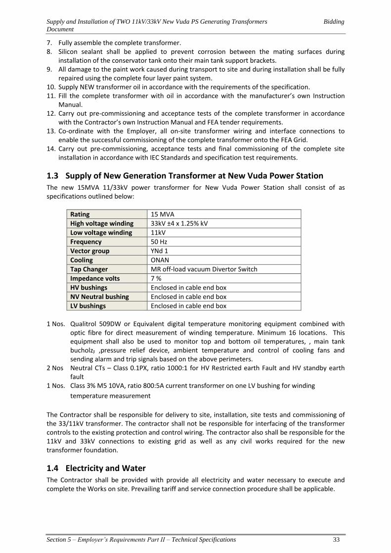
Supply and Installation of TWO 11kV/33kV New Vuda PS Generating Transformers Bidding
Document
Section 5 – Employer’s Requirements Part II – Technical Specifications 33
7. Fully assemble the complete transformer. 8. Silicon sealant shall be applied to prevent corrosion between the mating surfaces during
installation of the conservator tank onto their main tank support brackets. 9. All damage to the paint work caused during transport to site and during installation shall be fully
repaired using the complete four layer paint system. 10. Supply NEW transformer oil in accordance with the requirements of the specification. 11. Fill the complete transformer with oil in accordance with the manufacturer’s own Instruction
Manual. 12. Carry out pre-commissioning and acceptance tests of the complete transformer in accordance
with the Contractor’s own Instruction Manual and FEA tender requirements. 13. Co-ordinate with the Employer, all on-site transformer wiring and interface connections to
enable the successful commissioning of the complete transformer onto the FEA Grid. 14. Carry out pre-commissioning, acceptance tests and final commissioning of the complete site
installation in accordance with IEC Standards and specification test requirements.
1.3 Supply of New Generation Transformer at New Vuda Power Station The new 15MVA 11/33kV power transformer for New Vuda Power Station shall consist of as specifications outlined below:
Rating 15 MVA
High voltage winding 33kV ±4 x 1.25% kV
Low voltage winding 11kV
Frequency 50 Hz
Vector group YNd 1
Cooling ONAN
Tap Changer MR off-load vacuum Divertor Switch
Impedance volts 7 %
HV bushings Enclosed in cable end box
NV Neutral bushing Enclosed in cable end box
LV bushings Enclosed in cable end box
1 Nos. Qualitrol 509DW or Equivalent digital temperature monitoring equipment combined with
optic fibre for direct measurement of winding temperature. Minimum 16 locations. This equipment shall also be used to monitor top and bottom oil temperatures, , main tank bucholz, ,pressure relief device, ambient temperature and control of cooling fans and sending alarm and trip signals based on the above perimeters.
2 Nos Neutral CTs – Class 0.1PX, ratio 1000:1 for HV Restricted earth Fault and HV standby earth fault
1 Nos. Class 3% M5 10VA, ratio 800:5A current transformer on one LV bushing for winding
temperature measurement
The Contractor shall be responsible for delivery to site, installation, site tests and commissioning of the 33/11kV transformer. The contractor shall not be responsible for interfacing of the transformer controls to the existing protection and control wiring. The contractor also shall be responsible for the 11kV and 33kV connections to existing grid as well as any civil works required for the new transformer foundation.
1.4 Electricity and Water The Contractor shall be provided with provide all electricity and water necessary to execute and complete the Works on site. Prevailing tariff and service connection procedure shall be applicable.
Supply and Installation of TWO 11kV/33kV New Vuda PS Generating Transformers Bidding
Document
Section 5 – Employer’s Requirements Part II – Technical Specifications 34
1.5 Civil Works Civil works required for extension of existing concrete bund wall or construction of new bund wall and Fire blast wall shall be undertaken by the Employer. The contractor shall provide all necessary civil designs for the bund wall and fire walls for the Employer to construct. This shall include the all electrical cabling conduits required ect and general piping drawings layout. The construction of all civil works shall be the responsibility of the Employer.
1.6 Cable and Overhead Line Terminations The contractor shall submit details of the transformer LV and HV bushings for ordering of termination kits and clamps. All power cabling works and cable terminations as well as connections to the existing network will be supplied and installed by the Employer.
1.7 Training Training shall be provided before commencing the installation and commissioning of the relevant equipment at site. The contractor shall therefore submit the training program for each category along with the installation/erection and commissioning program and recommended manufacturer’s maintenance practice.
1.8 Objective of Training Modules The training program shall cover the installation, commissioning and maintenance aspects of the transformers and associated equipment as the trainee personnel will be responsible for commissioning witness by approving the tests & practices from the client’s side during the project implementation period and they also will be responsible for maintenance of such equipment after the expiry of defect liability period of the project. The training shall be held at the Employer’s office in Fiji and shall be conducted by an authority approved by the Manufacturer 1.9.1 Training Module No 1: Power Transformers Basic Contents:
Erection and installation of power transformers and tap changers
Testing and commissioning of power transformers and tap changers
Maintenance practices for the supplied power transformer as recommended by the Manufacturer as well as adjustment of connected devices and replacement of major parts
Maintenance practices for the off-load tap changer as recommended by the manufacturer
Installation and removal of online Digital Temperature Monitoring equipment.
Hands on training on test equipments, which are required for maintenance of installed equipment.
Procedures for oil filling and vacuuming the transformers. 1.9.2 Training Module No 2: Electronic Temperature Monitor, MR Instruments, ZIEHL- ABEGG
AG fan control and any other intelligent Instrument Basic Contents:
Introduction to the product
Operating principle
Overview of hardware and software
Input and output connections
Programming of the product
Front panel (manual) operations
Maintenance practices
Commissioning
Fault finding
Supply and Installation of TWO 11kV/33kV New Vuda PS Generating Transformers Bidding
Document
Section 5 – Employer’s Requirements Part II – Technical Specifications 35
Section 4 Employer’s Requirements - Part II Technical Specifications
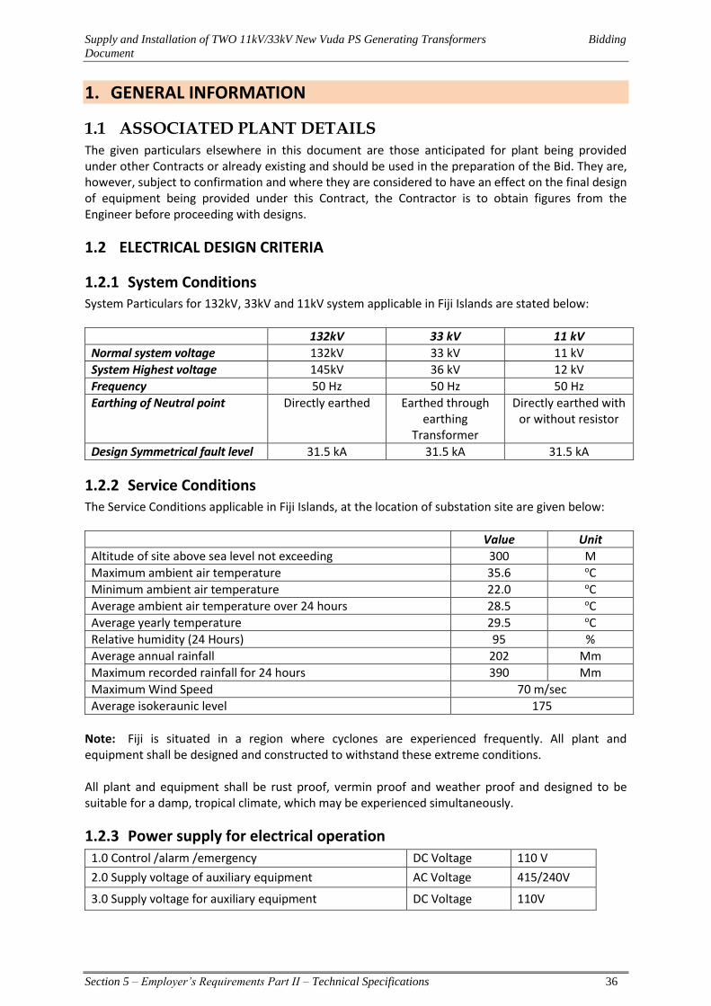
Supply and Installation of TWO 11kV/33kV New Vuda PS Generating Transformers Bidding
Document
Section 5 – Employer’s Requirements Part II – Technical Specifications 36
1. GENERAL INFORMATION
1.1 ASSOCIATED PLANT DETAILS The given particulars elsewhere in this document are those anticipated for plant being provided under other Contracts or already existing and should be used in the preparation of the Bid. They are, however, subject to confirmation and where they are considered to have an effect on the final design of equipment being provided under this Contract, the Contractor is to obtain figures from the Engineer before proceeding with designs.
1.2 ELECTRICAL DESIGN CRITERIA
1.2.1 System Conditions System Particulars for 132kV, 33kV and 11kV system applicable in Fiji Islands are stated below:
132kV 33 kV 11 kV
Normal system voltage 132kV 33 kV 11 kV
System Highest voltage 145kV 36 kV 12 kV
Frequency 50 Hz 50 Hz 50 Hz
Earthing of Neutral point Directly earthed Earthed through earthing
Transformer
Directly earthed with or without resistor
Design Symmetrical fault level 31.5 kA 31.5 kA 31.5 kA
1.2.2 Service Conditions The Service Conditions applicable in Fiji Islands, at the location of substation site are given below:
Value Unit
Altitude of site above sea level not exceeding 300 M
Maximum ambient air temperature 35.6 oC
Minimum ambient air temperature 22.0 oC
Average ambient air temperature over 24 hours 28.5 oC
Average yearly temperature 29.5 oC
Relative humidity (24 Hours) 95 %
Average annual rainfall 202 Mm
Maximum recorded rainfall for 24 hours 390 Mm
Maximum Wind Speed 70 m/sec
Average isokeraunic level 175
Note: Fiji is situated in a region where cyclones are experienced frequently. All plant and equipment shall be designed and constructed to withstand these extreme conditions. All plant and equipment shall be rust proof, vermin proof and weather proof and designed to be suitable for a damp, tropical climate, which may be experienced simultaneously.
1.2.3 Power supply for electrical operation 1.0 Control /alarm /emergency DC Voltage 110 V
2.0 Supply voltage of auxiliary equipment AC Voltage 415/240V
3.0 Supply voltage for auxiliary equipment DC Voltage 110V

Supply and Installation of TWO 11kV/33kV New Vuda PS Generating Transformers Bidding
Document
Section 5 – Employer’s Requirements Part II – Technical Specifications 37
1.2.4 Minimum Substation Clearances The transformer and its connections shall have electrical clearances as per IEC 60071 part 2 as listed in the following table: -
Highest system voltages between phases 145kV 36 kV 12 kV
Minimum clearance between live metal and earth and between live metal to neutral bushing
1300 mm 400 mm 250 mm
Minimum clearance between live metal of different phases and between high and low voltage windings
1300 mm 400 mm 250 mm
1.2.5 Pollution levels of Insulators and Bushings For substations with Heavy pollution level as per table 1 of IEC 60815, Phase to ground: 53.7mm/kV (at max operating voltage of 33kV)
1.2.6 Insulation Co-ordination The design of plant and equipment shall be such that insulation co-ordination is provided not only between different items of plant such as transmission line, surge arrestors, transformers, circuit breakers, but also between different components of items within a particular item of equipment.
1.2.7 Inter-Changeability Corresponding items or parts shall be interchangeable as far as possible.
1.2.8 Maintainability All plant and equipment supplied under this contract shall be maintainable. The contractor in adequate number of copies shall provide all necessary tools and equipment and operations and maintenance manuals required for this purpose. All special tools shall be supplied by the Contractor in 2 sets per transformer.
1.2.9 Ventilation Junction Box, cubicles and similar enclosed compartments shall be adequately ventilated to restrict condensation. All contactors, relay coils, etc. shall be suitably protected against corrosion and fully tropicalised.
1.2.10 Risk of Fire All apparatus, connections and cabling shall be designed and arranged to minimize the risk of fire and any damage, which might be caused in the event of fire.
1.3 QUALITY OF MATERIALS AND WORKMANSHIP All materials used under this contract shall be new and of the quality and highest class most suitable for working under the conditions specified and shall withstand the variations of temperature, atmospheric conditions arising under working conditions without distortion or deterioration or the setting up of undue stresses in any part and also without affecting the strength and suitability of the various parts of the work which they have to perform. All work shall be carried out and completed in a neat and professional manner to the approval of the Employer's Representative.
Supply and Installation of TWO 11kV/33kV New Vuda PS Generating Transformers Bidding
Document
Section 5 – Employer’s Requirements Part II – Technical Specifications 38
1.4 STANDARDS IEC Standards are to be adopted in general. British, IEEE or Australian standards too may be applied wherever necessary. Any other national or international standard may be used if such standards are not less exacting than corresponding IEC Standard. In all instances a copy of the relevant standard adopted should be forwarded to the Engineer. All works shall be carried out in accordance with the laws of Fiji and associated Acts and Regulations. These include: The Electricity Act (Chapter 180) – 1985 Health and Safety at Work Act – 1996 Environment Management Act In order to achieve Regulatory compliance under the Fiji Electricity Act, the Works shall comply with the Electricity Regulations and AS/NZS 3000:2000 “Wiring Rules”.
1.5 DETAILED DESIGN OF PLANT AND EQUIPMENT The detailed design of plant and equipment including plant layout, protection, control, supervisory interface equipment, earthing, civil works designs requirement etc. shall be carried out by the contractor in accordance with acceptable standards and codes of practice. Notwithstanding the specifications, technical schedules or plant requirements specified by the tender document, the successful contractor shall be fully responsible for ensuring that the design, manufacture or construction of all items of plant and equipment under this contract to be fully functional, compatible with each other technically and otherwise, complying with IEC and/or other relevant standards, and other safety regulations applicable, and to have the installation complete in all respects including finishing, painting, labelling etc. The successful contractor shall from the commencement of his contract submit to the Employer's Representative, his conceptual design, detailed designs, technical submissions, design, manufacture and construction drawings, etc. for approval at each stage until the completion of the project. The Employer's Representative will ensure that any revisions required, or in the absence of any such revisions the approval for such drawings technical submissions, designs or proposals shall be notified to the contractor within a reasonable time period.
1.6 PLANT AND EQUIPMENT TO BE SUPPLIED All items of plant and equipment supplied under this contract shall be of proven design, manufacture and construction, and shall have been in commercial operation for at least thirty (30) years. Tenderer should furnish a list of past orders, indicating the type of equipment, location, country etc. in support of this. Type test certificates or other certificates from independent international organizations may also be furnished. The Contractor shall guarantee the availability of spare parts for all items of plant and equipment for a period of at least 15 years.
1.7 INSPECTION AND TESTING Type test certificates shall be furnished for all items of plant and equipment with the tender. The Contractor at his cost shall carry out all routine tests as per relevant IEC or other standards. FEA will require one (1) of its representative to finalise the design with the factory Engineers at the factory offered by the successful tenderer, before approval for construction. The design review shall be for at least 3 days at the Manufactures place.
Supply and Installation of TWO 11kV/33kV New Vuda PS Generating Transformers Bidding
Document
Section 5 – Employer’s Requirements Part II – Technical Specifications 39
FEA will also require two (2) of its representative to inspect and carry out Factory Acceptance test the plant/equipment offered by the successful tenderer, before shipment, under this contract and to witness. ALL of the type tests (if type test reports of the particular model are not provided, then they shall be carried out for the plant manufactured and supplied) including routine tests and test specified in the specification. The associated cost, including return airfare international and domestic, 4.5 star accommodations, meals, and transportation from the hotel to the factory test site and airports shall be included in the tender price in the appropriate section. If any test fails and FEA has to schedule another (additional) trip to witness and ensure the relative testing meets the requirements of FEA, then the travel and accommodation costs shall be borne by the contractor. All commissioning tests shall be carried out in accordance with the relevant IEC or other equivalent or greater standards and tender specification. All tools and equipment and instruments for carrying out such tests shall be made available by the Contractor to Employer. The contractor shall provide the employer with a list of tools, equipment and test equipment required for commissioning the transformer. The preparation of a list of pre-commissioning and commissioning tests for each item of plant and equipment will be agreed upon with the Employer’s Representative at a later stage of the project. The pre-commissioning test and commissioning tests shall be carried out by the Contractor and the Employer’s representative. Results of the pre-commissioning tests shall be forwarded to the Employer for approval prior to commissioning of the transformers. All costs of carrying out the pre-commissioning and commissioning tests shall be borne by the Contractor. The Contractor shall provide all facilities for such tests or inspections to be carried out by the FEA’s representatives.
1.8 TRAINING OF FEA PERSONNEL The Employer requires its personnel (engineers and technicians) to be attached to be trained on installation, operation, maintenance of primary and secondary equipment to be supplied under this contract.
1.9 TOOLS AND EQUIPMENT The tenderer shall forward a list of tools and equipment required for operation and maintenance of the installation and include the cost of supplying such tools and equipment in the price Schedules.
1.10 SPARES The tenderer shall forward a list of manufacturer’s mandatory operational spare parts required for operation and maintenance of the plant and equipment supplied under this contract for a period of 15 years. The cost of supply of these spare parts shall form part of the contract. The tenderer shall also forward a list of optional spare parts which shall not form part of the contract but should be shown in a separate price schedule. The successful contractor shall ensure the availability of spare parts for operation and maintenance of all the items of equipment for a period of at least 15 years.
Supply and Installation of TWO 11kV/33kV New Vuda PS Generating Transformers Bidding
Document
Section 5 – Employer’s Requirements Part II – Technical Specifications 40
1.11 TECHNICAL LITERATURE - OPERATIONS AND MAINTENANCE MANUALS Tenderers shall furnish all technical literature, including catalogues, test certificates etc. in support of plant and equipment offered by him with the tender. The successful tenderer is to interface existing and new equipment drawings and a set of original drawings. Successful contractor shall forward four (4) binded hard copies of all operations and maintenance manuals, spare parts catalogues, detailed schematic and wiring diagrams and all other documents required for satisfactory operation and maintenance of the plant. The originals of the drawings in AutoCAD format (.DWG 2012 version) are required to be handed over. As built drawings are required to be furnished in 4 copies before the works are taken over as per Clause 5.6 & 5.7 of FIDIC Document (Conditions of Contract for Design – Build And Turnkey) edition 1. During the design and manufacture stage the contractor shall submit all design calculations, design drawings, technical submissions at each stage of design or manufacture for the approval of the Employer's Representative. The manuals shall include the following sections:
1.11.1 Plant Specification and Description The Plant Specification and Description Section shall include the specification and description of each plant item and system.
1.11.2 Installation and Commissioning The Installation and Commissioning Section shall include step-by-step procedures for the unloading, unpacking, transport, handling, assembly, erection, adjustment, alignment, preparation for service and testing of the plant.
1.11.3 Operation The Operation Section shall describe in detail the procedures for the preparation into service, setting, adjusting, checking before and during operation, routine testing and operating of the plant to be supplied. It shall provide complete information on operating limitations, allowable rates of temperature change, allowable temperature differentials and any other information required by operating staff to ensure the safe and efficient operation of the plant.
1.12 Maintenance The Maintenance Section shall contain sufficient detail to enable maintenance personnel to maintain the plant in good working condition and overhaul the plant from time to time. It shall describe and include pictorial representation of step-by-step procedures for dismantling, reassembly, alignment, replacement and adjustment of all components of the plant. This Section shall also include standards of workmanship, tolerances, air gaps, electrical resistance values, limits of wear, periodic adjustments, material specifications including special procedures (eg, heat treatment), weights of large items, details and uses of special tools, test equipment, jigs, gauges and tightening torque values for bolts. The Tenderer shall set down recommendations for preventive or condition based maintenance, including frequency of inspection and guidance in locating and rectifying faults and condition monitoring or diagnostic testing which may be performed on a regular basis. Similarly lubrication routines shall be specified including locations, recommended frequency and recommended type of lubricants.

Supply and Installation of TWO 11kV/33kV New Vuda PS Generating Transformers Bidding
Document
Section 5 – Employer’s Requirements Part II – Technical Specifications 41
1.13 TYPE TEST CERTIFICATES Copies of Type Test certificates for all plant and equipment shall be furnished as evidence in support of compliance with the specification. The Contractor shall furnish copies of certificates of all routine tests, inspection tests and any other type tests, which would have to be performed at a later stage.
1.14 SITE CONDITIONS The tenderer is required to ascertain for himself the Site Conditions, including limitations of space, geographical, climatic or other considerations. The tenderer shall satisfy himself of the suitability of the sites for the erection of the plant and equipment to be supplied.
1.14.1 SITE LOCATION
The construction works for the transformer pads, transportation to site, commissioning shall all undertake at the New Vuda PS FEA’s premises. The map below illustrates the location site. This site GPS Coordinates 177° 25' 49.07064" , -17° 40' 48.797832" FEA’s Vuda PS is located approximately 12km from Nadi Airport and 14km from Lautoka Wharf.
1.15 PACKING Equipment shall be carefully packed for transport and shipment in such a manner that it is protected from all dust and climatic conditions during loading, transport, unloading and subsequent storage in the open. Equipment shall be suitably packed and protected against vibration, movement and shock which may occur during loading and transport. Particular care in packing shall be taken when the

Supply and Installation of TWO 11kV/33kV New Vuda PS Generating Transformers Bidding
Document
Section 5 – Employer’s Requirements Part II – Technical Specifications 42
apparatus is transported by ship and road. The equipment shall also have tilt/inclination indicators to visually confirm that the equipment has been transported upright, Before dispatch from the factory the transformer shall be equipped with electronic impact recorders to monitor the impacts the transformer is subjected to while being transported from the factory to the site. The impact recorders shall not be dismantled until the transformer has been delivered to site and final reading has been taken. The electronic impact recorders should have capability of recording shock and vibration history with date and time stamping, together with GPS coordinates and have provision for extraction of the logs so that the data can be analysed on either vendor’s software, or on a spreadsheet format. The impact recorder’s battery should have enough capacity to power up the device for a minimum of 3 months. Upon completion of the project the impact recorders will be handed over to FEA.
Instruments and fragile items shall be packed separately. All items, which include delicate equipment, shall be sealed in polythene sheeting and silica gel desiccant or vapour corrosion preventive shall be inserted within the polythene packing. Straw shall not be used as packing material.
1.16 PROGRAMME AND PROGRESS OF WORK Programme Within 14 days of acceptance of the Tender the Contractor shall provide the Employer's Representative with (2) copies of the Programme of work covering design, manufacture, delivery and erection. The programme shall separately detail each item of equipment that is to be transported and delivered separately.

Supply and Installation of TWO 11kV/33kV New Vuda PS Generating Transformers Bidding
Document
Section 5 – Employer’s Requirements Part II – Technical Specifications 43
2. SECONDARY WIRING AND ANCILLARY ELECTRICAL APPARATUS
2.1 SECONDARY WIRING Secondary wires shall either be colour-coded or the terminals uniquely identified in compliance with AS/NZS 3000.
If wires are numbered, they shall be fitted with ‘Critchley Type 0’ ferrules (or their equivalent). Generally, the number identifying a particular wire shall change at the point of interconnection. If, however, the number is not to be changed, then this fact shall be clearly indicated on the ferrules at the end of each wire. No wires may be teed or jointed between terminal points.
All metallic cases of instruments, control switches, relays, etc., mounted on control panels or in cubicles, (Aluminium or stainless steel) shall be connected by means of green or green with yellow stripes PVC-insulated copper conductors of at least 4.5 mm2 section to the nearest earth bar.
Control and indication cables mounted on the surface of transformers, for example between the Buchholz relay and the marshalling box, shall be suitable for continuous operation at sheath temperatures up to and including 105°C. They shall, in addition, be protected against mechanical damage and ultraviolet radiation using flexible stainless steel wrap. Multi-core cables shall be terminated with weatherproof glands to BS 6121. Armoured cables shall be used for secondary wiring control cables at all times. All control panel wiring, secondary control wiring in motor starters, control gear and the like shall be carried out in a neat and systematic manner with cable supported clear of the panels and other surfaces at all points to obtain free circulation of air. In all cases, the sequence of the wiring terminals shall be such that the junction between multi-core and terminals is affected without crossover. Except where terminals are approved by the Employer’s Representative for use with bare conductors, claw washers or crimped connectors of approved type shall be used to terminate all small wiring. Insulating bushes shall be provided where necessary to prevent the chafing of wiring. All panel wiring shall comply with the requirements of BS.6231, Type A or B, as appropriate. Conductors shall be copper and have a minimum cross section equivalent to 50/0.25 mm (2.5 sq. mm), 7/0.67 mm (2.5sq. mm) or 1/1.78 mm (2.5 sq. mm) but single stranded conductors should only be employed for rigid connections which are not subject to movement or vibration during shipment, operating or maintenance. No Flexible conductor’s equivalent to 30/0.25 mm (1.5 sq. mm) or smaller sizes generally shall only be employed without written approval. For low voltage cabling and wiring, separate cables shall be used for each of the following groups:
1. auxiliary power supply 2. control and check back 3. measuring 4. communication
All control and power cables shall be armoured and all cables except those for auxiliary power supply must be in additional shielded with annealed copper tape. Cables shall conform to IEC 60228, IEC 60228A, IEC 60287, IEC 60811 & IEC 60885. Wire colours are preferably to comply with British Standard 158: Colour of wire Circuit particulars Red Red-phase connections in current and voltage transformer circuits only. Yellow Yellow-phase connections in current and voltage transformer circuits only.
Supply and Installation of TWO 11kV/33kV New Vuda PS Generating Transformers Bidding
Document
Section 5 – Employer’s Requirements Part II – Technical Specifications 44
Blue Blue- phase connections in current and voltage transformer circuits only. Green/Yellow Connections to earth. Black AC neutral connections, earthed or unearthed, connected to the secondary circuit
of current and voltage transformers. AC connections other than those above and connections in AC/DC circuits.
Brown DC indication circuits. Grey All other DC circuits. Alternatively, where equipment is wired in accordance with a manufacturer’s standard diagram, wiring may be carried out in a single colour except that all connections to earth shall be green. Wiring diagrams must indicate wire colours, numbers designated to all equipment/ instruments and shall be drawn as viewed from the back of the panel. All wires shall be fitted with numbered ferrules (hand written numbers are not accepted) of approved type at each termination. At points of inter-connection between wiring, where a change of numbering cannot be avoided, double ferrules shall be provided. Such points shall be clearly indicated on the wiring diagram. All secondary wiring to be performed at Site shall enter the terminal block at one side only. The panel wiring shall terminate in one or more terminal blocks accommodated at the side or bottom of each panel or compartment. Internal wiring between instruments or other devices not using the terminal block shall be permitted within the same compartment only. The markers on all wiring directly connected to circuit breaker trip coils, tripping switches, etc., shall be of a colour, preferably red, different from that of the remainder and marked “trip”. No wires may be teed or jointed between terminal points. Electrical wiring and instruments shall be so located that leakage of oil or water cannot affect them. Bus wiring between control panels, etc., shall be fully insulated and to be completely segregated from the main panel wiring. Generally, all signal, monitoring and protection circuits as well as shunt trips of circuit breakers shall be fed by DC. All other circuits may be controlled by AC. Also, contactor operating circuits shall be controlled by AC with the contactor solenoids preferably designed for DC with a pre-connected rectifier bridge.
2.2 TERMINAL BOARDS All terminal boards shall be mounted in accessible positions and, when in enclosed cubicles, are preferably to be inclined towards the door. Spacing of adjacent terminal boards shall be not less than 100mm and bottom of each board shall be more than 200mm above the incoming cable gland plate. Separate terminations shall be provided on terminal boards for the cores of incoming and outgoing cables including all spare cores. Where cores of multicore cables and internal cubicle wires have crimped ends, not more than two may be connected to any one terminal. When left bare, they shall have individual terminals and where bridging connections are necessary, these shall be incorporated in the terminal boards. Acceptable types of terminals are:
(i) Screw or stud type used with crimped ring type termination. Screws and studs shall be not less than of size M6, but stainless steel and bronze down to size M5 may be used, provided that the current carrying capacity is adequate. All studs shall be provided with nuts, washers and lock washers.
(ii) Inspection clamp type whereby the standard conductor or crimped termination is clamped between plates by a screw having a suitable locking device. Terminal entries shall be

Supply and Installation of TWO 11kV/33kV New Vuda PS Generating Transformers Bidding
Document
Section 5 – Employer’s Requirements Part II – Technical Specifications 45
shrouded such that not less than three full threads. Screws shall be of plated steel, stainless steel or phosphor bronze and size M3 or M4.
Terminal assemblies shall be to be of the unit form suitable for mounting collectively on a standard assembly rail, secured from the front and giving the required number of ways plus ten percent spare. LV AC and DC power circuit terminals shall be segregated form other terminals and shall be fitted with non-flammable plastic covers to prevent contact with any live parts. They shall have warning labels, with red lettering, mounted thereon in a conspicuous position. All connections shall be made at the front of the terminal boards and no live metal shall be exposed at the back. Insulating barriers shall be provided between each group of power circuit terminals and between the terminal categories, the height and the spacing being such as to give adequate protection to the terminals.
2.3 TERMINALS All terminals shall be mounted and positioned such that they are readily accessible and circuit numbers can be easily read. Terminations shall comply with ENA TS 50-18 for type "C" blocks and shall be of a type approved by the Employer.
To simplify the identification of circuit numbers, all terminal blocks shall be tilted towards the cubicle door by means of angle brackets. Shorting straps shall be used between terminal blocks to bridge identical conductor terminals. The a.c. and d.c. supply connections, and trip connections, shall be shielded at the terminal block by means of transparent insulated covers. All terminals having a circuit voltage of 240 V or higher shall be shielded with an insulated cover marked with a warning notice "Danger .....volts".
The minimum thickness of the terminal blocks shall be as follows:
Cable Size mm2 1.3 1.5 2.5 4 10
Minimum thickness of terminal block mm 6 6.5 6.5 8 10
The cooling control cubicle shall have at least 20% spare terminals fitted and enough extra space on mounting bars for another 20% terminals.
2.4 CONTROL SWITCHES AND PUSHBUTTONS Control switches and pushbuttons shall comply with BS EN 60947-5-1 OF 1992 or the relevant IEC standards.
2.4.1 General
Control switches for electrically operated circuit-breakers and motor operated disconnectors shall be of pistol grip or other approved discrepancy type and arranged to operate clockwise when closing the circuit-breakers and anti-clockwise when opening them. They shall be designed to prevent accidental operation. When switches of the discrepancy type are approved, operation is to be effected by two independent movements. Switches for other apparatus shall be operated by shrouded pushbuttons or to have handles of the spade type, the pistol grip type being reserved for circuit-breaker operation only. Control, reversing, selector and test switches shall be mounted, constructed and wired so as to facilitate the maintenance of contacts without the necessity for disconnecting wiring. Where necessary, control
Supply and Installation of TWO 11kV/33kV New Vuda PS Generating Transformers Bidding
Document
Section 5 – Employer’s Requirements Part II – Technical Specifications 46
switches shall be capable of being locked in appropriate positions but control switches for circuit breakers and for motor operated setting devices shall be of the non-locking type with spring return to the “neutral” position. Such switches shall be controlled by independent springs, the use of contact springs alone for restoring not being acceptable. All pushbuttons shall be of non-retaining type made of non-hygroscopic, materials, non-swelling and fitted to avoid any possibility of sticking. The contacts of all switches and pushbuttons shall be strong and to have a positive wiping action when operated. Control switches for use in direct control schemes shall be rated for substation battery voltage. All control switches shall be provided with labels in addition to clear indication as to the direction of each operation, for example, “open”, “close”, “raise”, “lower”, etc.
2.4.2 Electrical Control Locations
Equipment may be electrically controlled from a number of different control points as specified in the appropriate chapters of this Specification. The control positions shall be designated as follows: Local Control: Located adjacent to the item of plant to facilitate maintenance, inspection
and emergency operation. Remote Control: Located at a substation control room where specified items of Plant are
monitored and controlled by direct wire connection. Supervisory Control: located at a System Control Centre or where principal items of plant at a number of substations are remotely controlled via a SCADA (Supervisory Control and Data Acquisition) system.
2.5 ELECTRICAL MOTORS All AC motors shall be of the induction type in accordance with BS 5000: PART 99 OF 1973 and BS.5000, Part II, or IEC.60034, IEC 70072 and, unless otherwise specified shall have cooling type ICOI suitable for continuous operation and direct on-line starting. They shall be suitable in all respects for service under the conditions at site. Main conductor and slot insulation shall be non-hygroscopic and in accordance with Class B of BS 2757 or E of IEC 60085. If any motors supplied under this Contract shall be located outdoors, such motors shall be weatherproof and, where necessary, protected from overheating by the sun with a canopy of approved design. Motors shall be capable of operating continuously at rated output at any frequency between 48 and 51 cycles per second and at any voltage within 6% of nominal value. Motors shall be designed to operate for a period of not less than five minutes at a voltage of 25% below the nominal value and at normal frequency without injurious overheating. If required by the Employer’s Representative, the Contractor shall demonstrate that the motors comply with this requirement. Each motor shall be protected by a motor protective unit with adjustable thermal overcurrent and short circuit device. The starting current at full voltage is not to exceed six times the rated full load current. Motor bearings shall be of the rolling type and the cage locating the balls or rollers is not to be in contact with the racers. Vertical shaft motors shall have approved thrust bearings. The ends of motor windings shall be brought out to terminal boxes and the arrangement is such as to permit easy changing over of any two-phase leads. All terminals shall be fitted with an approved sealing chamber, conduit entry or adapter plate, as required, together with the necessary fittings to suit the type of cable supplied. Terminal boxes for motor housing shall be weatherproof to IP55 classification in IEC 60529. Terminals shall be of the stud type, of adequate size for the particular duty, marked in accordance with an approved standard. All terminal boxes shall be fitted with an approved sealing chamber, conduit entry or adaptor plate, as required, together with the necessary fittings to suit the type of cable specified. The terminal boxes shall be mounted below the motor to prevent ingress of moisture.
Supply and Installation of TWO 11kV/33kV New Vuda PS Generating Transformers Bidding
Document
Section 5 – Employer’s Requirements Part II – Technical Specifications 47
2.6 INDICATING LAMPS AND FITTINGS – EUROPEAN ISKRA Indicating lamps shall be of LED Schneider type and fitted into the fascias of switch and instrument cubicles or panels shall be adequately ventilated and shall be of LED type lamps for all indications. Lamps shall be easily removed and replaced from the front of the panel by manual means preferably not requiring the use of extractors. The bezel of metal or other approved material holding the lamp glass shall be of an approved finish so as to permit access to the lamp and lamp glass. The indicating lamps are to be free from any effects of corrosion, should be UV resistant and meet requirements of IP65 or equivalent standard. The viewing angle also to be approximately 180 degrees to enable visibility of indication without having to stand in front of the lamp. Terminals to be touch safe connections having IP2X rating. In addition, the lamp and fitting to be suitable for use in the following conditions:
Temperature : 20oC – 60oC
Humidity : 70% – 98% RH
The lamps shall be clear and shall fit into a standard form of lamp holder. The rated lamp voltage should be ten percent in excess of the auxiliary supply voltage, whether AC or DC. Alternatively, low voltage lamps with series resistors will be acceptable. The lamp glasses shall comply with BS 1376 and BS. 4039 and shall be in standard colours, red, green, blue, white and amber. The colour is to be in the glass and not to be interchangeable. Transparent synthetic materials may be used instead of glass, provided such materials have fast colours and are completely suitable for use in tropical climates. Lamps and relays incorporated in alarm fascia equipment may be arranged for normal operation from the station battery, subject to the approval of the Employer’s Representative. Lamp test facilities shall be provided so that all lamps on one panel can be tested simultaneously by operation of a common push-button. Where alarm fascias are specified, all alarm and monitoring indications (apart from circuit breaker and disconnector position indications) shall be incorporated in the fascia.
2.7 STARTERS AND CONTACTORS Contactors shall be of robust design and shall comply with IEC 60947. They shall operate without undue noise or vibration. Contactors shall be mounted in ventilated metal cubicles, to IP 65 classification in IEC 60529. The cubicles shall be complete with all locks, cable sealing boxes, busbars, internal wiring, terminal boards and accessories. All bare copper connections shall be taped and all secondary wiring shall be so arranged and protected to prevent damage from arcing.
Electrically held-in starters with integral interlocked isolators shall be used. If needed, auxiliary switches shall be included, for operating "red" and "green" indicating lights on remote instrument panels.
All motor contactors and their associated apparatus shall be designed to operate, without undue heating, for at least 5 minutes, at a voltage of 25% below the nominal value, and at normal frequency. If soft starters are used for the pumps there shall be one soft starter per pump circuit. The soft starter shall use frequency control only and not voltage control.
2.8 JUNCTION, TERMINAL BOXES AND TRANSFORMER CUBICLES All junction boxes, terminal boxes and marshalling kiosks shall be constructed of 4mm316 Grade stainless steel or cast iron. Each shall be provided with an earth stud. All main equipment shall be

Supply and Installation of TWO 11kV/33kV New Vuda PS Generating Transformers Bidding
Document
Section 5 – Employer’s Requirements Part II – Technical Specifications 48
arranged so that it is accessible from the front of the box or kiosk. All junction boxes, terminal boxes and marshalling kiosks shall be properly labelled as per the wiring diagrams. Enclosures for electrical apparatus are to afford the following degrees of protection classified in IEC.60529 of 1992 (BS.5490).
a) The cubicle shall be supplied mounted on the transformer.
b) It shall be made of stainless steel at least 4 mm thick to grade AISI stainless steel type 316 fully welded on the inside and outside to minimise corrosion.
c) It shall be fitted with a hinged door with a device that holds the door open at least 120 degrees. It shall be ventilated, have a drain and be weatherproof to IP 65 classification in IEC 60529. The ventilation and drain shall be insect and ant proof. The cubicle shall not be painted, but the outside surfaces shall be buffed.
d) The cubicle door shall be fitted with a multi-point locking device and handle suitable for padlocking.
e) All cubicles shall be mechanically isolated from the main tank via anti-vibration mounts.
f) The cubicle shall be equipped with a gear plate for mounting of all equipment.
g) The cubicle shall be equipped with terminals of the type detailed in this specification.
h) The cubicle shall have a cut out, not less than 150 mm x 80 mm at the bottom and covered with a detachable aluminium gland plate not less than 4 mm thick.
i) All 3-phase relays, contactors, isolating switches and thermal devices shall be marked with appropriate phase colours. Apparatus in which the phase elements are mounted horizontally shall be coloured red, yellow, blue from left to right when viewed from the front of the panel, and when mounted vertically they shall be coloured red, yellow, and blue from top to bottom.
j) The cubicle shall provide a clear space of at least 300mm high by the width of the cubicle for mounting of equipment.
k) Outdoor marshalling boxes or kiosks – IP65 - also provision of a thermostatically controlled 240 VAC anti-condensation heater and having screened drainage holes.
l) Auxiliary switches and associated terminals - IP65
m) Outdoor junction boxes - IP65
n) Outdoor instruments - IP65
o) Outdoor motors - IP65
p) Indoor control relay and low voltage AC & DC cubicles - IP65 – also thermostatically controlled 240V AC anti-condensation heater and indicating light common to a group of cubicles.
2.9 TRANSFORMER MARSHALLING KIOSKS The transformer ancillary apparatus shall be mounted in an approved heated and ventilated cubicle, attached to the transformer for the accommodation of the following equipment: -
Temperature indicators (Qualitrol 509DW or equivalent), cooler control “Auto-Hand” selector switch and test links and ammeter for the winding temperature indicator circuits as specified. Alternative offered shall supply detailed manual to Employer for approvals.
Control and protection equipment for the tap change gear including an isolating switch in the incoming circuit capable of carrying and breaking the full load current of the motor and of being
Supply and Installation of TWO 11kV/33kV New Vuda PS Generating Transformers Bidding
Document
Section 5 – Employer’s Requirements Part II – Technical Specifications 49
locked in the open position. Provision shall also be made for termination of secondary wiring of current transformers.
Control and protection equipment for the cooling plant including isolating switches in the incoming circuit each capable of carrying and breaking the full current of all cooling plant motor of one radiator bank and of being locked in the open position. The control facilities shall include a cooler selector switch, which can be padlocked in either position to select either cooler for remote control. Local control of the selected cooler shall be provided.
Terminal boards and gland plates including glands where specified for incoming and outgoing cables as per specification.
All doors shall be fastened by integral handle with provision for locking each door.
To prevent internal condensation an approved type of metal clad heater shall be provided, controlled by a watertight rotary switch mounted on the outside of the cubicle and a 5A fuse inside the cubicle.
A 240V AC single phase and three phase weather proof outlet shall be provided inside the transformer cubicle fitted with Residual Current Protection (RCD). The approved outlet is PDL, Clipsal and HPM brand. The outlet shall be fitted with a permanent label identifying it as being fitted with Residual Current Protection.
Lamp indications (RED) shall be provided for DC supply and AC supply into the transformer cubicle. The indications shall be wired from the main AC and DC supply wiring into the transformer cubicle.
All internal wiring shall be so placed as not to obstruct access. All wiring, connections, terminals, boards, and links shall be in accordance with the specification.
Labels in addition to those specified in General Technical Specification shall be provided on the outside of the kiosks to identify the compartments.
All three-phase relays, contactors, isolating switches and thermal devices shall be marked with appropriate phase colour. Apparatus in which the phase elements are mounted vertically they shall be coloured red, yellow, and blue from top to bottom.
2.10 GAUGE CUBICLES AND PANELS Gauge and instruments shall be grouped whenever possible and housed in suitable cubicles. Where circumstances do not justify cubicle accommodation, they may be secured to flat back panels but in such cases the approval of the Employer’s Representative is first to be obtained. Cubicles shall only be 316 grade stainless steel sheet metal having a minimum thickness of 4 mm. The construction shall employ folding techniques with the use of standard rolled sections or other reinforcement where necessary. The stiffness shall be such as to prevent mal-operation of relays or other apparatus by impact. The front of the panel shall have a smooth well-finished surface.
2.11 ANTI-CONDENSATION HEATERS All major items of electrical equipment susceptible to suffer from internal condensation from atmospheric or load variations shall be fitted with heating devices, suitable for electrical operation at 240 V a.c. 50 Hz single phase of sufficient capacity to prevent condensation. The electrical apparatus shall be designed not to exceed the maximum permitted rise in temperature if the heaters are energised while the apparatus is in operation. The supply to each heater shall have a fuse and an enclosed switch. The switch shall be arranged to switch the phase conductor only. There shall be no exposed live terminals. Thermostats shall not be fitted.
2.12 INTERIOR LIGHTS Each cubicle shall have a LED 15W, 240 V a.c. miniature fluorescent light fitting mounted horizontally or a heat resistant bayonet cap button holder complying with BS EN 61184 for a 240 V a.c., LED 15 W lamp. The light shall be mounted at the top of the cubicle and controlled by a door-activated switch.
Supply and Installation of TWO 11kV/33kV New Vuda PS Generating Transformers Bidding
Document
Section 5 – Employer’s Requirements Part II – Technical Specifications 50
2.13 CABLES AND CABLE LADDERS All 240/415 V power cables and control/indication/protection/alarm cables run along the external tank wall shall be securely fastened with stainless 316 Grade steel cable ties on stainless steel cable ladders. The struts fixing the cable ladders to the tank shall also be stainless steel.
Plastic cable ties and fully enclosed plastic or metal cable conduits with intermediate joints shall not be used. The external sheaths of the cables shall not be painted.
2.14 LABELS Labels shall be provided inside each junction box or kiosk to describe the functions of the various items of equipment. Where the kiosk is divided into compartments each door shall have an external label to identify the compartment.
2.14.1 Labels and Instruction Plates on Instruments
Labels written in the language(s) indicated by the Employer’s Representative shall be provided for all instruments, relays, control switches, push buttons, indication lights, breakers, etc. In the case of instruments, switches and control switches where the function is indicated on the dial plate or on the switch escutcheon plate, no label is required. Relays shall be clearly labelled according to their function in the circuits, and to their related equipment, which shall be identical to the designations as used in the circuit manuals. Instruction plates in English language showing the sequence diagrams or cautions for maintenance shall be fitted inside of the front door of the electrical switchboards. Sample of writings shall be submitted before hand for approval to the Employer’s Representative.
3.14.2 Labels and Identification for Conduits, Boxes, etc.
The interior of each piece of equipment shall be clearly marked to show the phases and, for this purpose, either coloured plastic discs screwed to fixed components, or identification by means of plastic sleeving, or tape shall be used. All conductors shall have their outer covering coloured to the phase colour or, alternatively, appropriately coloured plastic sleeves may be utilized at all cable terminations in fuse-boards, switchgear, etc.
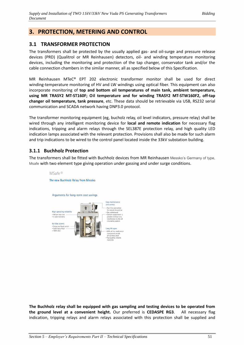
Supply and Installation of TWO 11kV/33kV New Vuda PS Generating Transformers Bidding
Document
Section 5 – Employer’s Requirements Part II – Technical Specifications 51
3. PROTECTION, METERING AND CONTROL
3.1 TRANSFORMER PROTECTION The transformers shall be protected by the usually applied gas- and oil-surge and pressure release devices (PRD) (Qualitrol or MR Reinhausen) detectors, oil- and winding temperature monitoring devices, including the monitoring and protection of the tap changer, conservator tank and/or the cable connection chambers in the similar manner, all as specified below of this Specification. MR Reinhausen MTeC® EPT 202 electronic transformer monitor shall be used for direct winding-temperature monitoring of HV and LW windings using optical fiber. This equipment can also incorporate monitoring of top and bottom oil temperatures of main tank, ambient temperature, using MR TRASY2 MT-ST160F; Oil temperature and for winding TRASY2 MT-STW160F2, off-tap changer oil temperature, tank pressure, etc. These data should be retrievable via USB, RS232 serial communication and SCADA network having DNP3.0 protocol. The transformer monitoring equipment (eg, bucholz relay, oil level indicators, pressure relay) shall be wired through any intelligent monitoring device for local and remote indication for necessary flag indications, tripping and alarm relays through the SEL387E protection relay, and high quality LED indication lamps associated with the relevant protection. Provisions shall also be made for such alarm and trip indications to be wired to the control panel located inside the 33kV substation building.
3.1.1 Buchholz Protection
The transformers shall be fitted with Buchholz devices from MR Reinhausen Messko’s Germany of type,
Msafe with two element type giving operation under gassing and under surge conditions. The Buchholz relay shall be equipped with gas sampling and testing devices to be operated from the ground level at a convenient height. Our preferred is CEDASPE RG3. All necessary flag indication, tripping relays and alarm relays associated with this protection shall be supplied and
Supply and Installation of TWO 11kV/33kV New Vuda PS Generating Transformers Bidding
Document
Section 5 – Employer’s Requirements Part II – Technical Specifications 52
under this Contract. Each transformer shall be fitted with gas and oil-actuated Bucholz relay equipment having alarm contacts, which close on collection of gas or low oil level, and tripping contacts which close following oil surge conditions. The gas and oil actuated relay shall be connected on the piping connection from the main conservator to the tank. The bucholz relay will be mounted without having a tilt of greater than 1 degree from the horizontal. Each gas and oil-actuated relay shall be provided with a test cock to take a flexible pipe connection for checking the operation of the relay. Each relay shall be fitted with a calibrated glass window for indication of gas volume. To allow gas to be collected at ground level, a small bore pipe shall be connected to the gas release cock of the gas and oil-actuated relay and brought down to a point approximately 1400 mm above ground level, where it shall be terminated by a cock which shall have provision for locking to prevent unauthorised operation. The design of the relay mounting arrangements, the associated pipe work and the cooling plant shall be such that mal-operation of the buchholz relays will not take place under normal service conditions under all operating temperatures. The pipe work shall be so arranged that all gas arising from the transformer will pass into the gas and oil-actuated relay. The oil circuit through the relay must not form a delivery path in parallel with any circulating oil pipe, or is to be teed into or connected through the pressure relief vent. Sharp bends in the pipe work shall be avoided and not permissible. When a transformer is provided with two conservators the gas and oil-actuated relays shall be arranged as follows: -
(a) If the two conservators are connected to the transformer by a common oil pipe one relay shall be installed in the common pipe.
(b) If the two conservators are piped separately to the transformer two relays shall be installed, one in each pipe connection.
The clearance between oil pipe work and live metal is to comply with the specifications as specified. The connection pipe between the conservator tank and the transformer main tank shall be fitted with a gas operated (Buchholz) relay for the protection of the transformer. The connection pipe shall have the same bore as the relay. Buchholz relays shall not operate under any of the following conditions:
a) Due to the operation of the pumps. b) Due to movement of the transformer by earthquakes. c) Due to magnetic fields either on energising the transformer or due to the fault currents
in conductors creating field intensities in air of up to 0.07 Tesla.
Stop valves shall be provided on both sides of the relay, and as near as possible to the Buchholz relay. The stop valves shall have clearly marked ‘open’ and ‘closed’ positions visible from ground level. A means of securing the valves in the ‘open’ position is required, preferably without needing to use key locking devices.
Transformer construction shall allow any rising gas to readily reach the Buchholz relay(s) and not be trapped. If necessary, piping shall be provided to lead away any gas that could be trapped in any part of the main tank. The relay shall be provided with both "Trip" and "Alarm" contacts wired to the cooling control cubicle.
Piping and petcocks shall be provided so that gas and air can be released from the Buchholz relay and air can be injected into the top and bottom of the relay (this tests the operation of the contacts). Petcock movement shall be prevented by securing them to the transformer tank. The gas bleed pipe shall be fitted with a readily accessible gas trap suitable for taking gas samples from a height of 1.4 m above ground level. The required pressure of the air injected through the bottom connection to test
Supply and Installation of TWO 11kV/33kV New Vuda PS Generating Transformers Bidding
Document
Section 5 – Employer’s Requirements Part II – Technical Specifications 53
the trip contact shall not exceed 2,000 mbar. The piping shall be 10 mm diameter and all threads shall comply with ISO 7/1.
3.1.2 Temperature Indicating Devices and Alarms
The transformers shall be provided with a MR Reinhausen MTeC® EPT 202 or equivalent alternative electronic transformer monitoring device for direct measurement of HV and LV winding hot spot temperature and measurement of the transformer oil temperature as well. The device should provide the following indications:
(a) Top tank temperature (b) Bottom tank temperature (c) Ambient temperature (d) HV winding temperature (e) LV winding temperature (f) Main tank pressure
All required sensors and gadgets shall be provided to enable monitoring of the above parameters. The winding temperature indicators shall be housed in the transformer marshalling cubicle. Outputs of the Qualitrol IED 509DW/Dynamic Rating or MR Reinhausen MTeC® EPT 202 should be used for remote alarm and tripping associated with the auxiliary protection. The following functions shall be provided:
(a) Top oil temperature alarm (b) Top oil temperature trip (c) LV winding temperature alarm (d) LV winding temperature trip (e) HV winding temperature alarm (f) HV winding temperature trip
Dynamic Rating DRMCC equipment shall be used combined with optic fiber probes to get the direct hot spot temperature measurement of the HV and LV windings. The Dynamic Rating unit shall have the following enhancements apart from the standard features: 1. Loss of life calculation
2. Seasonal cooling setback 3. Adaptive ambient control 4. Low temperature loackout 5. Auxiliary current setpoint capability 6. DNP3 communications protocol
All electrical and mechanical parameters of the transformer required for input in to the Qualitrol 509DW shall be provided by the transformer manufacturer. The unit shall be complete with fiber optic and all required accessories to enable direct winding temperature functionality. Fiber optic used with this application shall be of the type approved by Qualitrol for the 509DW equipment. Optical feed through and tank wall plate shall be used for connection of the fiber optic through the transformer tank. The wall plate for the fiber shall be welded to the transformer tank. The 509DW shall be mounted in the transformer marshalling kiosk and be used for other monitoring, alarm and trip functions.

Supply and Installation of TWO 11kV/33kV New Vuda PS Generating Transformers Bidding
Document
Section 5 – Employer’s Requirements Part II – Technical Specifications 54
3.1.3 Tank Pressure Monitoring
The main tank shall be connected with a pressure transducer/relay from Qualitrol which measures the tank pressure. This relay shall be connected to the Qualitrol 509DW for monitoring of the transformer tank pressure.
3.1.4 Oil Level Indicators
Oil level indicators shall be supplied for both main tank and OLTC conservator tanks. The oil level indication shall be clearly visible to an observer on the ground.
Each indicator shall have contacts for high and low oil level alarms. The contacts shall be wired to the cooling control cubicle.
Dial type magnetic oil level indicators shall be used, not a prismatic type. The indicated range of oil levels shall correspond to average oil temperatures of -20°C to140°C.
The oil level at 20°C, 40°C, 60°C, 80°C, and 1000°C shall be marked on the gauge. A separate plate giving temperature/graduation equivalence is not acceptable. Employer’s preference is MESSKO of Germany
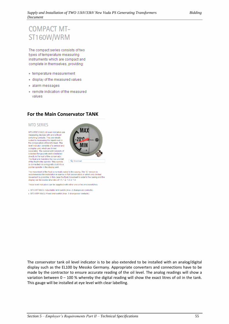
Supply and Installation of TWO 11kV/33kV New Vuda PS Generating Transformers Bidding
Document
Section 5 – Employer’s Requirements Part II – Technical Specifications 55
For the Main Conservator TANK
The conservator tank oil level indicator is to be also extended to be installed with an analog/digital display such as the EL100 by Messko Germany. Appropriate converters and connections have to be made by the contractor to ensure accurate reading of the oil level. The analog readings will show a variation between 0 – 100 % whereby the digital reading will show the exact litres of oil in the tank. This gauge will be installed at eye level with clear labelling.
Supply and Installation of TWO 11kV/33kV New Vuda PS Generating Transformers Bidding
Document
Section 5 – Employer’s Requirements Part II – Technical Specifications 56
3.1.5 ZHEL ABEGG Automatic Timer Fan Control
The fan control circuit shall be fitted with an automatic timer to turn on all the cooling fans for any selectable 30 minute time period during the day. The automatic timer shall be fitted with fail safe protection such that failure of the automatic timer does not prevent operation of the fans by the WTI or cause the fans to run continuously.
3.1.6 Dissolve Gas Analysing Equipment
A minimum of two valves each from top and bottom tank shall be provided on the main tank for future connection of dissolved gas analysis equipment. The height of the valves shall be 1m abover ground. The pipes shall be 316 stainless steel grade and provision to take oil samples out on yearly basis.
3.1.7 Pressure Relief Device
An approved pressure relief device of MESSKO MPreC which shall be independent of electrical power, of sufficient size shall be provided for the rapid release of any pressure that may be generated in the tank and designed to operate at a static pressure lower than the hydraulic test pressure called for in Schedule of Works Tests. In the event that the device is a spring operated valve type, it shall be provided with at least two normally open signalling contacts to trip the transformer and remote alarm/indication purposes. The relief device is to be mounted on the main walls above the level of the winding and is to be provided with a skirt to project at least 25 mm into the tank to prevent gas accumulation. The device shall be capable of maintaining oil tightness of the transformer under all conditions of normal service. A cover or other arrangement shall be provided so that any oil discharges are in a downward direction avoiding adjacent or ancillary equipment. The design of the device shall be such that gas cannot accumulate around it inside the tank, nor moisture can enter it from the outside of the tank. This cover must not impair the function of the device and the openings shall be protected by suitable sized mesh to prevent birds nesting. A resettable indicator visible to a person on the ground shall be provided to show that the relief valve has operated. Overpressure device shall not generate invalid trip signals by tank vibrations and by the magnetic fields generated during normal operation and during through-faults. Each device shall: 1. Maintain its oil tightness under a static oil pressure equal to the static operating head of oil
plus 50kPa; 2. Attain its full opening in not more than 2.5 ms when subjected to an internal pressure impulse
equal to the static operating head of oil plus 50kPa; 3. Be capable of withstanding full internal vacuum at sea level; 4. Be fitted with a visual operation indicator plainly visible and accessible from ground level, and
arranged for manual resetting;
3.1.8 Oil and Winding Temperature
Qualitrol 509DW or equivalent electronic transformer monitor with fiber optic shall be utilised for direct winding temperature measurement of the HV and LV winding temperatures. The 509DW shall also be used to measure top and bottom oil temperature using conventional platinum (PT100) probes mounted into oil pockets on the transformer tank.
Supply and Installation of TWO 11kV/33kV New Vuda PS Generating Transformers Bidding
Document
Section 5 – Employer’s Requirements Part II – Technical Specifications 57
Remaining inputs in the Qualitrol 509DW can be utilised for monitoring the load tap changer oil temperature, ambient temperature, main tank pressure and any other suitable parameter as may be suitable. Local display of the above parameters shall be programmed in the Qualitrol 509DW. Output relays of the 509DW shall be utilised for remote alarm and trip facilities for the above parameters and shall be wired up to the terminal block in the transformer marshalling kiosk. All necessary flag indication, tripping relays and alarm relays associated with this protection shall be supplied under this Contract.
Supply and Installation of TWO 11kV/33kV New Vuda PS Generating Transformers Bidding
Document
Section 5 – Employer’s Requirements Part II – Technical Specifications 58
4. TRANSFORMER
4.1 TYPE OF TRANSFORMER AND OPERATING CONDITIONS
4.1.1 General
All transformers shall be oil immersed and suitable for outdoor installation and shall comply with IEC 60076, IEC 60137, 60214 & 60289. Only transformers from manufactures with a minimum of thirty years successful experience on manufacturing transformers with comparable size will be accepted. Each item or function which is obviously necessary for the proper completion of the work, it’s full functionality and safety as well as complete interfacing with other work, whether especially specified in the tender documents or not, shall be included in the tender price.
4.1.2 Prohibited Materials Asbestos materials, materials containing PCB’s, or other materials prohibited by the Fiji Statutory Regulations shall not be used in the construction of the transformer. A certificate to this effect shall be included in the transformer manual.
4.1.3 Design Review The Employer may arrange for an independent confidential design verification review to be carried out. The Manufacturer shall provide all the requested design and construction data required to enable the Employer to adequately evaluate the transformer to be supplied.
4.1.4 Component Approvals a) The components and fittings associated with transformers covered in this specification shall
be nominated in the Tender Schedules and is subject to approval of the Employer. b) Samples, technical literature, drawings, test reports and lists of the names of the principal
users, with experience gained, shall be supplied. c) The manufacturer shall submit components to the Employer for approval only after these
have been initially approved by the manufacturer for use on the transformer. The use of standardised and approved components already in use on the Employer’s existing power transformers is preferred to minimize the variety of spares required.
d) All contactors, switches, circuit-breakers, relays and contacts incorporated in the electrical control of tap-changers shall be subject to the Employer’s approval.
4.2 RATING AND OPERATION
4.2.1 Transformer Capacity
(i) Rating
The transformer shall be rated for continuous operation as follows under the service conditions.
1. IEC 60076 11/33 kV Rating 2. The HV/LV, 11/33 kV continuous rating shall be 15 MVA on all tapings with ONAN cooling to the
temperature rise limits of IEC 60076 Part 2. 3. IEC 60076 Rating Maximum Hot Spot Temperature
The maximum allowable winding hot spot temperature shall not exceed 68oC at an ambient temperature of 35oC, using a winding temperature hot spot gradient factor as determined by magnetic leakage field plots at the IEC 60076 Part 2 continuous ONAN rating on all tappings. IEC 60076 33 kV/11kV Minimum ONAN Rating
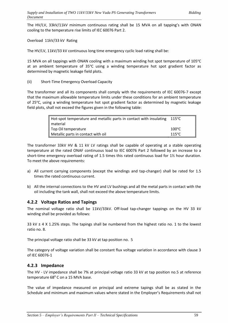
Supply and Installation of TWO 11kV/33kV New Vuda PS Generating Transformers Bidding
Document
Section 5 – Employer’s Requirements Part II – Technical Specifications 59
The HV/LV, 33kV/11kV minimum continuous rating shall be 15 MVA on all tapping’s with ONAN cooling to the temperature rise limits of IEC 60076 Part 2.
Overload 11kV/33 kV Rating
The HV/LV, 11kV/33 kV continuous long time emergency cyclic load rating shall be:
15 MVA on all tappings with ONAN cooling with a maximum winding hot spot temperature of 105oC at an ambient temperature of 35oC using a winding temperature hot spot gradient factor as determined by magnetic leakage field plots.
(ii) Short-Time Emergency Overload Capacity
The transformer and all its components shall comply with the requirements of IEC 60076-7 except that the maximum allowable temperature limits under these conditions for an ambient temperature of 25oC, using a winding temperature hot spot gradient factor as determined by magnetic leakage field plots, shall not exceed the figures given in the following table:
Hot-spot temperature and metallic parts in contact with insulating material
115oC
Top Oil temperature 100oC Metallic parts in contact with oil 115oC
The transformer 33kV HV & 11 kV LV ratings shall be capable of operating at a stable operating temperature at the rated ONAF continuous load to IEC 60076 Part 2 followed by an increase to a short-time emergency overload rating of 1.5 times this rated continuous load for 1½ hour duration. To meet the above requirements:
a) All current carrying components (except the windings and tap-changer) shall be rated for 1.5
times the rated continuous current.
b) All the internal connections to the HV and LV bushings and all the metal parts in contact with the oil including the tank wall, shall not exceed the above temperature limits.
4.2.2 Voltage Ratios and Tapings
The nominal voltage ratio shall be 11kV/33kV. Off-load tap-changer tappings on the HV 33 kV winding shall be provided as follows:
33 kV ± 4 X 1.25% steps. The tapings shall be numbered from the highest ratio no. 1 to the lowest ratio no. 8. The principal voltage ratio shall be 33 kV at tap position no. 5
The category of voltage variation shall be constant flux voltage variation in accordance with clause 3 of IEC 60076-1
4.2.3 Impedance
The HV - LV impedance shall be 7% at principal voltage ratio 33 kV at tap position no.5 at reference temperature 680 C on a 15 MVA base. The value of impedance measured on principal and extreme tapings shall be as stated in the Schedule and minimum and maximum values where stated in the Employer’s Requirements shall not
Supply and Installation of TWO 11kV/33kV New Vuda PS Generating Transformers Bidding
Document
Section 5 – Employer’s Requirements Part II – Technical Specifications 60
be subject to tolerance. Where transformers are required to operate in parallel with existing units the appropriate data will be stated in the Employer’s Requirements.
4.2.4 Zero Sequence Impedances
The Contractor shall nominate the zero sequence impedances in Technical Data Schedule of this specification.
4.3 TRANSFORMER CORE The construction method shall be of the core type and shall be from Japan JEF or equivalent from EUROPE. Core laminations shall be of the highest quality non-ageing grain-orientated steel or better. The nominal flux density at any part of the core shall not exceed 1.5Tesla at rated voltage and frequency at principal tap, and there shall be no risk of saturation under the above and all other operating conditions. All parts of the core and fixings shall withstand any shock to which they may be subjected during lifting, transport, installation and service (including switching and external short circuits) and earthquakes. Permanent lifting eyes and other suitable means shall be provided to enable the core and windings to be litfted.
The core and frames shall be single-point earthed as follows: All internal metal parts of the transformer, with the exception of the individual core laminations, core bolts and associated individual clamping plates shall be bonded and earthed. A single connection from the core and another single connection from the frame shall be brought out separately via cables to two 5kV bushing terminals, complete with shorting links, mounted in an external box located next to a hand hole cover in the tank top. The bushings shall be labelled “C” for the core and “F” for the frames in a permanent manner. To allow for testing of the insulation of the core and frame, the connections shall be earthed via a removable bolted link to an earthed stud on the tank. The cables, bushings and links shall be rated for the maximum circulating current in the event the core of the frame becomes inadvertently grounded.
In the event that the core or frame becomes inadvertently grounded, the single-point earth cables, bushings and links shall be rated for a circulating current rating equivalent in number of Amperes to three times the value of the three phase transformer MVA power rating to IEC 60076.
The bottom frame supporting the core shall have two metal feet on each longitudinal axis side extending to the full width of the tank to stabilise the complete core and winding assembly when de-tanked and resting unsupported on the ground. The complete core and winding assembly shall not be attached to the transformer tank cover. The insulation within the core (cooling ducts), between the core and end frames and between the core and support feet shall be Class H insulation. Cellulose insulation shall not be used. A detailed drawings and design of the earthing shall be part of the Transformer manual.
4.4 WINDING All windings shall have copper conductors from SAM DONG KOREA. Transformer 33kV Wye connected windings may have graded insulation as defined in IEC 60076-3 and 11 kV winding shall have uniform insulation as defined in IEC 60076. All neutral points shall be insulated to withstand an applied voltage test specified in the Employer’s Requirements. The windings shall also be thoroughly seasoned during manufacture by the application of axial pressure at a high temperature for such length of time as will ensure that further shrinkage is unlikely to occur in service. The windings and leads of all transformers shall be braced to withstand the shocks, which may occur through rough
Supply and Installation of TWO 11kV/33kV New Vuda PS Generating Transformers Bidding
Document
Section 5 – Employer’s Requirements Part II – Technical Specifications 61
handling and vibration during transport, switching and other transient service conditions including external short circuit. If the winding is built up of sections or of disc coils splitted by spacers, the clamping arrangements shall ensure that equal pressures are applied to all columns of spacers. Regardless of the mode of cooling specified in accordance with IEC 60076-2 Clause 3, the transformer windings shall have fully directed oil flow consisting of the following:
1. Oil from the radiators directed into the bottom of each winding. 2. Directed oil flow within each winding by means of zig zag cooling directed flow washers.
Klakbands shall not be used. 3. The transformer winding conductors and conductor connections shall be constructed from
high conductivity copper and shall be burr free and profiled. 4. All electrical connections within windings shall be brazed or welded to withstand shocks of
the type that might occur through handling, vibration during transport, switching, earthquakes and other transient fault service conditions. Soft soldered connections are not acceptable.
5. All connections from windings shall be mechanically sound, supported and fastened to prevent movement and damage under transport, site erection, and normal and abnormal operating conditions.
6. If a brazed crimp or crimp joint is used to connect the winding lead-out and the lead connection, the Contractor shall state the type of joint to be used and the method of stress relieving; both of which shall be subject to the approval of the Employer.
7. All cylinders/wraps shall be made of pre-compressed transformer board. Machined wrapped paper cylinders/wraps are not acceptable.
8. Scarfed overlap shall be used for forming cylinders and angle collars. Overlaps shall be formed on duct strips
9. Only moulded angle collars/caps shall be used from high density pre-compressed boards with contoured edges. Petalled collars/caps are not acceptable.
10. Metal backed paper shall not be used in the stress relieving of winding to lead connections. 11. Metal backed paper shall not be used in the manufacture of the stress shields without the
express approval of the Employer. 12. Enamel covered wires shall only be used when approved by the Employer and shall also meet
the following additional criteria: (a) The particular enamel and method of use has a proven history. (b) For continuously transposed cable the radial thickness of the enamel shall be 0.1 mm. (c) For helical windings that are transposed by hand, the cross-over/transposition shall be
mechanically and electrically protected. 13. There shall not be any electrical out of balance of turns between the phase windings. 14. Duct strips shall be of a solid construction one piece and have contoured edges– duct strips
made of multiple strips tied together are not acceptable. All duct strips and spacers shall have contoured edges.
15. All paper covered conductors shall use thermally upgraded paper. 16. Continuously transposed cable shall: 17. Be epoxy bonded to withstand free buckling short-circuit forces unless it can be proved
otherwise in accordance with Clause 6.2. 18. Utilise a spacer between strand stacks to keep the stacks separate. 19. All crossovers and transpositions are to be under bent so that after compression, the
crossover/transposition does not protrude into the adjacent radial duct. 20. All crossovers, transpositions and winding lead outs are to be effected by a pre-set bender to
ensure that they are correctly bent and are uniformly identical. 21. Winding conductors shall use butt lapped insulation papers for all layers except for the final
outer layer which shall be overlapped.
Supply and Installation of TWO 11kV/33kV New Vuda PS Generating Transformers Bidding
Document
Section 5 – Employer’s Requirements Part II – Technical Specifications 62
22. All internal winding and bushing lead support structures shall use fibreglass nuts and bolts. Wooden or cellulose based nuts and bolts shall not be used. The winding and lead support structures shall not rely on the shear strength of the fibreglass nuts and bolts.
23. All winding coils shall be sized for correct height in a vapour phase oven. 24. Paperless LV windings are not acceptable. 25. Winding Assembles shall be prepared as follows:
a. The individual cylinders/wraps and their associated duct strips shall be pre-dried to minimize shrinkage.
b. Each winding shall be clamped under the design load (kN) as determined from the short circuit loadings and the design pressures as used in compressing the complete active part.
c. A single ring shall be used to compress all windings for each limb d. Any blocking required shall be distributed such that the HV, FR and LV windings retain
their design force balance e. Each winding shall be clamped complete with the entire end blocking in place.
4.5 COOLING The types of cooling shall be as stated in the Employer’s Requirements and the letters relating to the method of oil circulating and cooling used in this Specification and Employer’s Requirements shall be in accordance with IEC 60076. Where a combination of two methods of cooling is applied to one transformer as for ONAN units, the transformer shall be capable of operating under the ONAN condition as stated in the Employer’s Requirements, after which the cooling equipment is to come into operation and the Transformer will operate as an ONAF unit. Transformers shall be fitted with tank mounted radiators. They shall be capable of remaining at the operation of full load for 60 minutes in the event of failure of blowers associated with both coolers without the calculated winding hot spot temperature exceeding 1050C. Failure of one fan in each group of blowers shall not reduce the continuous maximum rating of the transformer.
4.6 CONTINUOUS MAXIMUM RATING Transformers shall have the continuous maximum rating as stated in the Employer’s Requirements and shall comply with the requirements as regards temperature rise and overloads on all tapings irrespective of the direction of power flow and with the voltage of the lower voltage winding at the normal voltage stated in the Employer’s Requirements. To allow for high atmospheric temperatures, the allowable temperature rise shall be reduced as stated in this Specification. The overload capability shall be in accordance with IEC 60354.
4.7 ELECTRICAL CONNECTION Transformer windings shall be connected in accordance with the IEC 60076 group symbol specified in the Employer’s Requirements. The neutral point shall be brought out of the tank and earthed outside of the tank. All electrical connections within windings shall be brazed but subject to approval, mechanically crimped joints may be used for round stranded conductors on tapping, bushing or earthing connections and on bundle conductors when design has been proved by the type test and application is subject to rigorous quality control.
4.8 ABILITY TO WITHSTAND SHORT CIRCUIT
4.8.1 General
All transformers shall be capable of withstanding on any tapping and without damage the thermal and dynamic effects of external short circuits under the conditions stated in IEC 60076 Part 5. For at least 3 seconds at rated conditions and after all loading conditions as specified in IEC 60354.
Supply and Installation of TWO 11kV/33kV New Vuda PS Generating Transformers Bidding
Document
Section 5 – Employer’s Requirements Part II – Technical Specifications 63
4.8.2 Calculations and Tests
Evidence shall be submitted with the Tender as to the extent to which the manufacturer has proved or is able to prove either by calculation or test the ability of the specified Transformers to withstand thermal and mechanical effects under short circuit. The transformer shall be designed to ensure that leakage flux does not cause overheating in any part of the transformer. The Tenderer shall submit a reference list of at least ten (10) transformers of same or similar design and rating manufactured and supplied by the manufacturer for orders from outside the country of the manufacture. Offered transformer will only be accepted if transformers identical/similar in design have a minimum of ten years field experience.
4.8.3 EXTERNAL SHORT-CIRCUIT WITHSTAND
Transformers shall be designed and constructed to withstand, without damage, the thermal and dynamic effects of external short-circuit under the conditions specified in IEC 60076-5. The appropriate value of short-circuit apparent power shall be taken from the following table:
System Highest Voltage (kV) Short Circuit Apparent Power (MVA)
12 2,000
36 2,500
A current of 3 seconds duration shall be used to calculate the thermal ability to withstand short-circuits. The radial short circuit strength of windings shall be based on the free buckling mode. The interior parts of transformer shall be designed and constructed to withstand without damage the mechanical forces caused by the following:
a. Short-circuit currents as detailed above. b. Transportation impact forces of 1 g or greater. c. Seismic earthquake loadings as detailed in specification.
4.8.4 LOSSES AND EVALUATION OF LOSSES
The Tenderer shall state in the Technical Particulars and Guarantees, guaranteed values for component losses of the total loss which shall be as low as is consistent with transport restrictions, reliability and economic use of materials. Tenders will be assessed on the basis of the least 'Present Worth' of capital cost plus guaranteed losses, being the sum of the installed Tender Price of the transformers plus: No load losses - 6000 Fijian Dollars/kW, 20kW Copper losses - 3000 Fijian Dollars/kW The acceptance of transformers yielding component losses higher than the guaranteed values shall be governed by either of the following: - (A) Component losses in excess of guaranteed values but within the tolerance permitted under IEC 60076 Part 1.
Transformers shall be accepted subject to full compliance with all technical particulars including temperature rises at CMR and subject to the Tenderer accepting deduction from the Contract Price of charges for each kW on part thereof of component losses in excess of the guaranteed values, at the above evaluation rates.
(B) Component losses in excess of guaranteed values and exceeding the tolerance permitted under IEC 60076 Part 1. The acceptance of transformers shall be entirely at the discretion of the Employer’s Representative/Employer and subject to the Tenderer accepting the
Supply and Installation of TWO 11kV/33kV New Vuda PS Generating Transformers Bidding
Document
Section 5 – Employer’s Requirements Part II – Technical Specifications 64
deduction from the Contract Price of charges for each kW on part thereof of component losses in excess of the guaranteed values, at the above loss evaluation rates.
In the event of transformers, which are, either equal to or below the guaranteed losses values, the Tenderer will not be entitled to any premium in respect of reduction in losses below the guaranteed values.
4.9 Service Conditions The transformers shall be constructed for directly connected to an overhead transmission circuit and switched into or out of service together with its associated transmission circuit. The service conditions are:
a) The ambient temperature range is 10°C to +50°C. b) 100% humidity, with very rapid temperature fall, can occur. c) The altitude does not exceed 1200m. d) Earthquakes are expected. e) Lightning are expected. f) Atmosphere can be heavily polluted with salt, dust and products from agricultural spraying.
4.10 NOISE The transformer noise levels shall be measured as a type test and in accordance with IEC 60551. The noise level of the transformers shall be as stated in the Employer’s Requirements. When the bottom plate of the transformer tank will be in direct contact with the surface of the foundation anti-vibration pads shall be provided for insertion between the transformer and its foundation. The anti-vibration pads to be made from high quality electrometric rubber specially compounded to resist ageing, oil and water.
4.11 Audible Sound Level a) Measurement and calculation of sound power levels shall comply IEC 60076-10 b) The permissible maximum sound pressure level for the transformer operating at 15MVA
measured 5 metres from the transformer shall not exceed 40 dB(A) with the transformer energised to 100% voltage on the principal tap and rated frequency with ONAN.
c) The permissible maximum sound power level for the transformer operating at maximum rating of 15MVA measured 5 metres from the transformer shall not exceed 45 dB(A) with the transformer energised to 100% voltage on the principal tap and supplied auxiliaries operating (i.e. fans, etc).
4.12 CORONA INCEPTION FIELDS Under Induced and Impulse test voltage conditions, there shall be at any particular stress point a minimum 35% safety margin between the corona inception field strength and the actual figure determined from the field plots supplied by the Contractor for all oil ducts in both axial and radial dimensions. The corona inception field strength shall be referenced to the published curves A 41-5 (2) and A 41-6 (2) in Weidmann Book Band 1, Volume 1.
4.13 HARMONIC SUPPRESSION Transformers shall be designed with particular attention to the suppression of harmonic voltages, especially the third, fifth and seventh harmonics and to minimize the detrimental effects resulting there from and as to minimise waveform distortion and any possibility of high frequency disturbances, inductive effects or of circulating current between the neutral points at different transforming stations reaching such a magnitude as to cause interference with telecommunications circuits.
Supply and Installation of TWO 11kV/33kV New Vuda PS Generating Transformers Bidding
Document
Section 5 – Employer’s Requirements Part II – Technical Specifications 65
4.14 MAGNETIC CIRCUIT AND WINDINGS
4.14.1 Magnetic Circuit
The design of the magnetic circuit shall be such as to avoid static discharges development of short circuit paths internally or to the earthed clamping structure, and the production of flux components normal to the plane of the laminations. Each lamination shall be insulated with a material stable under the action of pressure and hot oil. The winding structure and major insulation shall be designed to permit an unobstructed flow of cooling oil through core cooling ducts to ensure efficient core cooling. The magnetic circuit shall be insulated from all structural parts, and shall be capable of withstanding a test voltage to core bolts and to the frame of 2,500 volts RMS for one minute. In order to allow testing, the magnetic core shall be earthed to the tank cover at one point only through removable links in an appropriate terminal box, placed in an accessible position on the tank cover. The core shall be free from over-fluxing liable to cause damage or mal-operation of the protection equipment when operating under continuous over-voltage operation specified in the schedule.
4.14.2 Flux Density
Core shall be constructed from cold rolled grain oriented steel sheets. Design shall be such that there will be no adverse effects due to core or stray flux heating with the quality of steel employed, and that when operating under the most onerous conditions envisaged in IEC 60076 and IEC. 60354, flux density in any part of the magnetic circuit does not exceed 19,000 lines per square centimetre (i.e. 1.5 Tesla). The maximum flux density in the legs and yokes of the core shall not exceed 1.5 Tesla at rated voltage and frequency during normal operation; that is, with the rated primary voltage applied to the primary terminals at the principal tap and rated frequency. Over-fluxing of the core shall not occur under this condition. The cores, framework, clamping arrangement and general structure of the transformer shall be capable of withstanding any shocks to which they may be subjected during transportation, installation and service. Adequate provisions shall be made to prevent movement of internal parts of the transformer relative to the tank and the method of supporting the core structure in the tank.
4.15 WINDING CONNECTIONS The HV 33 kV windings shall be connected in wye (star) and the LV 11 kV windings shall be connected in Delta. The HV/LV connection symbol shall be as follows:
YNd1
Winding reconnection facilities shall be provided to reconnect the LV terminals such that the transformer can be rotated physically 1800, without altering its original phase rotation.
The winding reconnection facilities for the LV winding shall be achieved via removable bolted links under oil inside the main tank. A removable access hatch on the main tank shall be provided to allow the LV winding to be re-connected from Standard to Non Standard operation.
The transformer LV winding connections prior to shipping from the manufacturer’s factory shall be confirmed by Employer prior to final factory acceptance testing.
4.16 THERMAL AND MOISTURE MONITORING Transformers shall be dried by vapour phase and the maximum temperature shall not exceed 130oC. For the transformers and coils subject to air drying and vacuum dry-out, the maximum temperature in air shall be limited to 105oC and under vacuum 110oC.
Supply and Installation of TWO 11kV/33kV New Vuda PS Generating Transformers Bidding
Document
Section 5 – Employer’s Requirements Part II – Technical Specifications 66
A roll of 25 mm wide insulating paper, about 100 mm in diameter (the same as the paper used in the windings and leads) shall be attached to and dried out with the windings. The insulating paper roll shall be fastened in an accessible position on the top yoke near the centre limb and above the windings, to ensure the roll is as close to the hottest spot as possible. Samples of this roll shall be taken before and after dry-out to measure the change in the Degree of Polymerisation (DP). The minimum sample shall be 1250 DP This roll shall stay in the transformer during the transformer’s life and shall be used to monitor insulation moisture content levels during commissioning and during the life of the transformer. Likewise, samples of the insulation board are required for monitoring insulation moisture content levels during commissioning and during the life of the transformer. Six such samples shall be secured at a readily accessible position near a hand hole cover within the transformer tank. Each sample shall be approximately 100 mm2.
4.17 FIBRE OPTIC TEMPERATURE PROBES Fibre optic temperature probes shall be inserted to verify calculated winding hot spot temperatures (as determined by leakage field analysis), during final heat run performance testing. A total of 16 fibre optic probes shall be inserted as follows:
a) 9 probes shall be inserted in the hottest phase (phase B) as detailed below:
(i) HV Winding 2 probes at top of winding, 2probesat bottom of winding (ii) LV Winding 2 probes at top of winding, 2probesat bottom of winding
(iii) Tapping Winding
1probe at top of winding
b) 4 probes shall be inserted in the other 2 phases (cooler phases A and C) as detailed below:
iv) HV Windings Top of winding (phases A and C)
v) LV Windings Top of winding (phases A and C)
c) 3 probes shall be inserted for oil measurement as detailed below:
vi) 2 probes at the top of the HV and LV oil duct on phase B for top oil temperature
measurement vii) 1 probe in the bottom oil chamber for bottom oil temperature measurement
The precise positioning of each fibre optic probe, e.g. the actual disc layer and the inner or outer circumference of the disc layer shall be determined and agreed during the detailed Design Review based on leakage field analysis. The fibre optics shall be terminated on the outside of the tank in a suitable weatherproof housing.

Supply and Installation of TWO 11kV/33kV New Vuda PS Generating Transformers Bidding
Document
Section 5 – Employer’s Requirements Part II – Technical Specifications 67
4.18 Fibre Optic Probe Monitor One LumaSMART Controller from ‘LUMASENSE Technologies’ with a DNP3 communications output shall also be offered as an item in price schedules.
The LumaSMART Controller shall be mounted inside or beside the control cubicle adjacent to the temperature monitor. The unit shall be connected via fibre optic extensions to the 16 fibre optic probes fitted within the transformer and will monitor the internal winding temperatures while the transformer is in service.
4.19 Internal Earthing (i) General - All metal parts of the transformer with the exception of the individual core
laminations, core bolts and associated individual clamping plates shall be maintained at same fixed potential.
(ii) Earthing of Core Clamping Structure - The top main core clamping structure shall be connected to the tank body by a copper strap. The bottom main core clamping structure shall be earthed by one or more of the following methods.
(a) by connection through vertically tie rods to the top structure; (b) by direct metal to metal contact with the tank base maintained by the weight of the
core and windings; (c) by connection to the top structure of the same side of the core as the main earth connection to the Tank. (iii) Earthing of Magnetic Circuits - The magnetic circuit shall be earthed to the clamping
structure at one point only through a removable link placed in an accessible position just beneath an inspection opening in the tank cover and which, by disconnection, will enable the insulation between the core and clamping plates, etc., to be tested at voltages up to 2.5 kV. The link shall have no detachable components and the connection to the link shall be on the same side of the core and the main earth connection. These requirements are compulsory.
Magnetic circuits having insulated sectional construction shall be provided with a separate link for each individual section. The arrangement of the connections shall be subjected to the plane of the laminations divide the magnetic circuit into two or more electrically separate parts, the ducts and insulating barriers which have a thickness greater than 0.25 mm are to be bridged with tinned copper strips so inserted as to maintain electrical continuity.
(iv) Earthing of Coil Clamping Rings - Where coil clamping rings are of metal at earth potential, each ring shall be connected to the adjacent core clamping structure on the same side of the Transformer as the main earth connection.
(iv) Size of Earthing Connections - Main earthing connections shall have a cross-sectional area of
not less than 95 sq. mm. but connections inserted between laminations may have cross-sectional areas reduced to 25 sq. mm. when in close thermal contact with the core.
4.20 Earthing Terminals External earthing terminals shall be provided as follows:
a) Two earthing terminals located on the transformer tank, each one on opposite sides of the
tank wall and located near to ground level for connection to the substation earth grid.
Supply and Installation of TWO 11kV/33kV New Vuda PS Generating Transformers Bidding
Document
Section 5 – Employer’s Requirements Part II – Technical Specifications 68
b) One earthing terminal located on any separate associated radiator bank and located near to ground level.
c) One earthing terminal for the neutral current transformer mounting bracket. The earthing
terminal shall be located near the top of the tank wall, underneath the neutral current transformer mounting bracket.
d) The external earthing terminals shall be a flat vertical lug, 100 mm x 50 mm, and drilled with two 14 mm diameter holes for M12 bolts, at 45 mm vertical centres. The terminals shall be stainless steel, suitable for use with copper earthing connections, rated for 3 s of at least 31.5 kA. The earth terminals shall be located so they are readily accessible from both sides of the foundation pads. Dimension details of the arrangement offered shall be supplied with the tender.
e) Every part of the equipment intended to be earthed shall be electrically continuous with the earthing terminals without relying upon fortuitous contacts. The earth lug shall be marked with an ‘earth’ symbol. An adequately rated electrical bond shall be provided across all bolted joints of the tank.
4.21 CABLE END BOX 33kV and 11kV HV/LV cable box shall be air insulated. The box shall have connections for 6 x single core, 630 mm2 XLPE-insulated, copper wire screened, PVC-sheathed cables per phase.
The 33 kV cable box shall be supplied with 7 split gland plates. The gland plates shall be marine grade 8 mm thick aluminium. The 11 kV cable box shall be supplied with 6 split gland plates. The gland plates shall be marine grade 8 mm thick aluminium. The arrangement shall allow cables to be connected to a separate terminal plate mounted on stand-off insulators on the back of the cable box. Each terminal plate shall be connected, by easily removable copper links, to the HV winding bushing.
The cable box shall have an open front design such that the cables can be slid into their final termination position. The top of the front opening in the cable box shall be equal to or greater than the height of the internal main busbars to allow easy access for bolting of the cable termination palms at site.
The front bolted cover of the cable box shall be marine grade 8 mm thick aluminium and fitted with two lifting handles. One lifting handle shall be positioned on the left hand side of the cover and one on the right hand side of the cover such that two people can lift the cover off for regular maintenance access inside the cable box.
The cable box design shall be such that with the cables supported at the gland plate (the support is part of this Contract), then with the cable box access cover removed and the gland plate unbolted, that the transformer and cable box can be removed.
The front of the cable box shall have an infra red window to enable cable termination temperature checks to be performed while the transformer is in service.
The cable box shall have sufficient support structures between the main tank and the cable box such that the cable box can bear the additional weight of two 100 kg people standing on or in the cable box without the need for additional vertical supports installed under the bottom of the cable box.

Supply and Installation of TWO 11kV/33kV New Vuda PS Generating Transformers Bidding
Document
Section 5 – Employer’s Requirements Part II – Technical Specifications 69
Removable insulated barriers shall be provided between the phases.
The cable box internal air electrical clearances shall comply in accordance with the system highest voltage requirements.
Except for the internal electrical clearances, the cable boxes shall comply with the requirements of BS 6435: 1984, and also the following specific requirements:
a. They shall be suitable for through currents determined from this specification.
b. They shall be suitable for earth fault currents equivalent to the system MVA fault levels.
c. Electrical clearances with cables connected to the terminals shall be such as to provide the
impulse withstand strength.
d. A pressure relief vent such as a square panel of at least 0.2 m2. The sides shall be sufficiently strong such that the vent panel cannot become detached from the cable box. The panel shall open at a pressure of at least 50 kPa lower than the internal withstand pressure of the cable box.
e. The air filled cable box shall be fitted with one dehydrating breather to prevent internal condensation. The breather shall be accessible to a person standing at ground level and fitted with 2 kg of dehydrating material.
f. The bottom of the cable box shall be at least 1000 mm from the bottom of the transformer
tank.
g. The bushing to cable connections (solid or flexible) shall be supplied by the Contractor and the Employers preference is from ABB Sweden.
h. The positioning of the cable to bushing connections shall be mechanically restrained in such a
manner as to meet the short circuit conditions as specified in this specification.
i. The cable box shall have the following earthing facilities:
i. An earth bar for the separate connection of each individual cable’s screen. The earth bar shall be mounted on stand-off insulators with a removable connection from the earth bar to an earth stud on the cable box wall to facilitate testing. The earth bar shall be located outside the cable box no more than 300 mm from the cable entry to enable in service cable testing. Each cable screen shall be brought outside the cable box through an insulation gland to connect separately onto the earth bar.
ii. The cable box earthing points mentioned above shall be bonded together, and then
connected to the transformer tank.
iii. The cable box shall be weatherproof to IP 65 XX classification in IEC 60529. Where the cable box is bolted on to the main transformer tank, flange mountings for the gasket seal shall be provided.
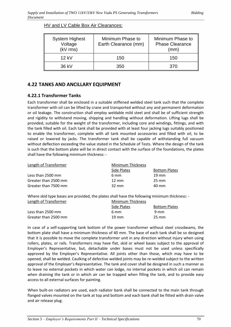
Supply and Installation of TWO 11kV/33kV New Vuda PS Generating Transformers Bidding
Document
Section 5 – Employer’s Requirements Part II – Technical Specifications 70
HV and LV Cable Box Air Clearances:
System Highest Voltage (kV rms)
Minimum Phase to Earth Clearance (mm)
Minimum Phase to Phase Clearance
(mm)
12 kV 150 150
36 kV 350 370
4.22 TANKS AND ANCILLARY EQUIPMENT
4.22.1 Transformer Tanks
Each transformer shall be enclosed in a suitable stiffened welded steel tank such that the complete transformer with oil can be lifted by crane and transported without any and permanent deformation or oil leakage. The construction shall employ weldable mild steel and shall be of sufficient strength and rigidity to withstand moving, shipping and handling without deformation. Lifting lugs shall be provided, suitable for the weight of the transformer, including core and windings, fittings, and with the tank filled with oil. Each tank shall be provided with at least four jacking lugs suitably positioned to enable the transformer, complete with all tank mounted accessories and filled with oil, to be raised or lowered by jacks. The transformer tank shall be capable of withstanding full vacuum without deflection exceeding the value stated in the Schedule of Tests. Where the design of the tank is such that the bottom plate will be in direct contact with the surface of the foundations, the plates shall have the following minimum thickness: - Length of Transformer Minimum Thickness Side Plates Bottom Plates Less than 2500 mm 6 mm 19 mm Greater than 2500 mm 12 mm 25 mm Greater than 7500 mm 32 mm 40 mm Where skid type bases are provided, the plates shall have the following minimum thickness: - Length of Transformer Minimum Thickness Side Plates Bottom Plates Less than 2500 mm 6 mm 9 mm Greater than 2500 mm 19 mm 25 mm In case of a self-supporting tank bottom of the power transformer without steel crossbeams, the bottom plate shall have a minimum thickness of 40 mm. The base of each tank shall be so designed that it is possible to move the complete transformer unit in any direction without injury when using rollers, plates, or rails. Transformers may have flat, skid or wheel bases subject to the approval of Employer’s Representative, but, detachable under bases must not be used unless specifically approved by the Employer’s Representative. All joints other than those, which may have to be opened, shall be welded. Caulking of defective welded joints may be re-welded subject to the written approval of the Employer’s Representative. The tank and cover shall be designed in such a manner as to leave no external pockets in which water can lodge, no internal pockets in which oil can remain when draining the tank or in which air can be trapped when filling the tank, and to provide easy access to all external surfaces for painting. When built-on radiators are used, each radiator bank shall be connected to the main tank through flanged valves mounted on the tank at top and bottom and each bank shall be fitted with drain valve and air release plug.

Supply and Installation of TWO 11kV/33kV New Vuda PS Generating Transformers Bidding
Document
Section 5 – Employer’s Requirements Part II – Technical Specifications 71
4.22.2 Construction
Weldable structural steel of an approved grade to BS 7668, BS EN 10029, BS EN 10025 and BS EN 10210 or equivalent shall be used in construction. Each transformer shall be enclosed in a suitably stiffened welded steel tank suitable for outdoor service and designed so the transformer can be transported. When fully oil filled, the transformer shall be able to be jacked, lifted, and hauled into place without permanent deformation or leakage.
Tank wall stiffeners shall be of the vertical type to minimise corrosion of the surfaces and to allow for the option of sand filling inside the stiffeners for noise control. Sand filling inside the tank wall stiffeners for additional noise control shall be agreed during the Design Review at the manufacturers’ works.
The design of the tank and cover shall not have any external pockets or dips in which water can lodge or pond, or internal pockets in which oil can remain when draining the tank or in which air can be trapped when filling the tank. The same applies to spaces under access covers.
The tank design shall provide for easy access to all external surfaces for painting. Joints around access openings, bushings and any other removable accessories shall be bolted, and an electrical bond provided across the bolted joint.
All external edges shall have a minimum 3 mm radius to ensure adequate paint thickness.
4.22.3 Cover
Each tank cover shall be of adequate strength, must not distort when lifted and shall be provided with suitable flanges having sufficient and properly spaced bolts. Inspection openings shall be provided to give access to the internal connections of bushings, winding connections and earthing links. Each opening shall be correctly located and must be of ample size for the purpose of which it is intended. All inspection covers shall be provided with lifting handles. Tank covers with low level welded flanged joints are preferred, but contractors may offer alternative designs with high level covers. It must be possible to remove any bushing without removing the tank cover and adequate access chambers shall be provided for this purpose. A bolted or welded cover may be used for the main tank cover. If a welded cover is used ‘MIG’ welding shall be used to weld the cover to the main tank. The core and windings shall not be suspended from the main tank cover. The top of the tank cover shall be fitted with two Uni-Anchor Plates with Tie-Off Anchors, manufactured by Unique Concepts Ltd (Part No. 17415 - stainless steel version), for safety harness attachments.
4.22.4 Thermometer Pockets
Pockets shall be provided for a stem type thermometer and for the bulbs of temperature indicators where specified. These pockets shall be located in the position of maximum oil temperature and it must be possible to remove any bulb without lowering the oil level in the tank. Captive screwed caps shall be provided to prevent the ingress of water to the thermometer pockets when they are not in use. Thermometer pockets shall comply with the requirements of BS 2765 and be located according to IEC 60076-2.
4.22.5 Access Openings
Openings shall be provided in the main tank to give access for in-situ tightening of the core and windings without removing the main tank or the main tank cover. Openings shall be provided in the tank to give access to the internal connections of all bushings, earthing connections, CT secondaries,

Supply and Installation of TWO 11kV/33kV New Vuda PS Generating Transformers Bidding
Document
Section 5 – Employer’s Requirements Part II – Technical Specifications 72
and tap-changers. The opening shall give unimpeded internal access and shall be of ample size for the purpose intended.
All access openings shall have flanges welded to them by means of continuous welds both on the inside and the outside of the flange. To make it easy to fit covers to the openings, the flanges shall have drilled and tapped blind holes to accommodate the studs. Access openings to be available from both sides of the transformer inclusive of the top and bottom areas. The opening should be adequate to allow clear visible inspection from the nearest winding to the furthest.
All access covers shall be provided with lifting handles.
4.22.6 Lifting Jacking and Haulage
The transformer tank shall be provided with attachments (front, rear, and both sides) for lifting, jacking, and haulage. Lifting lugs shall be strong enough to lift, without distortion, the complete transformer when full of oil.
Jacking pads shall be provided, two on each side of the tank, extending perpendicularly from the tank, with a minimum effective size of 200 mm length and 150 mm width. The jacking pads shall have a minimum clearance from the tank base of 300 mm.
Haulage eyes shall be provided on each side and each end of the transformer tank. They shall be located symmetrically about the tank centre line, 200 mm to 300 mm above the base of the tank and perpendicular to the tank. A hole, at least 50 mm in diameter, shall be provided for the eye, and at least 100 mm of free working space shall be provided above and below each haulage eye.
4.22.7 Pressure and Vacuum Withstand
The complete tank with all fittings and pipework shall withstand full vacuum (-1014 millibars gauge), and an internal pressure of 50 kPa without permanent deformation or leaks. The Contractor shall test the tank in accordance with Clauses 6.5.7and 6.5.8 to prove compliance with the above.
4.22.8 Mounting of Bushings
a. Each bushing shall be mounted on an annular steel ring equipped with studs and designed to the following specifications:
b. Outside diameter = flange diameter of the bushing. c. Inside diameter = lower portion bushing diameter plus 12 mm d. Minimum thickness = 1.5 x diameter of fixing studs e. Each ring shall be fixed to the outside surface of the cover or tank by means of
continuous welding around both the internal and external circumferences. f. Stainless steel studs shall be fitted to the mounting ring.
4.22.9 Bushing Turret Bleeds
Air bleed pipework for trapped air and combustible gases shall be provided for all bushing turrets. The air bleed and trapped gas pipework shall be connected to the main tank Buchholz relay.
4.22.10 Gun Studs
Stainless steel gun studs shall be used for all stud fittings on the external surfaces of the main tank. Subject to the approval of the Employer, the following alternative method of stud installation may be used: Stainless steel threaded rods inserted into tapped blind holes - provided a suitable method for preventing moisture ingress into the tapped blind holes is used.

Supply and Installation of TWO 11kV/33kV New Vuda PS Generating Transformers Bidding
Document
Section 5 – Employer’s Requirements Part II – Technical Specifications 73
4.22.11 Conservator Tank
Each transformer shall be provided with an overhead conservator tank formed of substantial steel plates and arranged above the highest point of the oil circulating system. Connections into the main tank shall be at the highest point to prevent the trapping of air or gas under the main tank cover. Main tank conservator vessels shall be equipped with elastic diaphragms of the air-bag type. The capacity of each conservator tank shall be adequate for the expansion and contraction of oil in the whole system under the specified operating conditions. Conservator tanks shall also be provided with a cleaning door, filling cap, filter and drain valve with captive cap and a prismatic type oil level indicator of MR Reinhausen MESSKO brand or equivalent in each compartment. Each oil level indicator shall have the minimum and maximum levels indication and alarm contacts. The main conservator tank shall be provided with a partitioned chamber, with the same diameter as the main tank conservator, for the tap change conservator. The tap change conservator shall also be fitted with a MESSKO maintenance free dehydrating breather and an oil level gauge with alarm contacts.
All bolted connection plates of the conservator tank supports shall be a non-corrosive material that does not require painting. The material may be either a non-magnetic black steel or stainless steel. The conservator tank supports that are bolted to the side wall of the main tank shall have bottom stops welded on the tank side wall to hold the supports in place when bolted into position during site assembly. Access for inspection, cleaning and painting of the main tank and tap change conservator chambers shall be provided via one of the following two options:
1. Removable end plates, or
2. Sealed end plates but with an opening at the top of the main tank chamber of a sufficient
size to allow entry and for the tap changer chamber removal of the oil level gauge to allow entry.
The second of the above two options is preferred.
Conservator tanks shall be provided with a filling cap, drain valve with captive cap, and oil level gauge. The conservator shall have the same pressure and vacuum withstand, and be tested in the same manner as the transformer tank specified.
Gusset plates or other reinforcing members shall be so arranged as to ensure the free passage of oil along the bottom of the conservator. The location of the conservator tank shall not obstruct the removal from the tank of equipment such as the tap-changer.
The conservator for the main tank shall be of the fully sealed type to prevent oxygen, moisture, and particles from entering into the transformer oil. It shall consist of:
i. An impermeable synthetic cell type rubber membrane that separates the oil from the air.
ii. A breather connected to the airside of the rubber membrane at 1400mm above the transformer base.
iii. A sump. iv. An oil level gauge with alarm contacts. v. An air release valve to permit bleeding off air during filling of the transformer or when in
service. vi. An oil handling facility.
Supply and Installation of TWO 11kV/33kV New Vuda PS Generating Transformers Bidding
Document
Section 5 – Employer’s Requirements Part II – Technical Specifications 74
Inspection covers shall be provided to permit inspection of the rubber membrane without dismantling the conservator. The internal surfaces of the conservator shall be varnished to resist corrosion. The design of the conservator shall be such that internal re-treatment (of the conservator) and replacement of the rubber membrane can be easily carried out. The conservators shall have sufficient capacity to accommodate expansion and contraction of the oil due to temperature changes from -5°C to 120°C.
4.22.12 Dehydrating Breathers MESSKO brand MTraB® DB200 and Air Dryers
The location of the conservator tank shall be so arranged that it does comply with the requirements and a valve shall be provided at the conservator to cut off the oil supply to the tank. Each conservator shall be fitted with maintenance free dehydrating breather of MESSKO brand MTraB®
DB100T. Due to the climatic conditions at site, this breather shall be larger than what would be fitted for use in a temperate climate. All breathers shall be mounted at a height of approximately 1400 mm above ground level. Breathers for the power transformer main tank conservator shall have a minimum filling capacity of 3 kg. The pipe work between the conservator and the transformer tank shall comply with the requirements and a valve shall be provided at the conservator to cut off the oil supply to the tank.
4.22.13 Valves and Location
All valves up to and including 75 mm bore shall be made of gunmetal. Each Transformer shall be fitted with the following valves as required for:-
a) Draining the case (flanged-gate valve) b) Sampling oil from the extreme bottom and top of the case. c) Lower filter press connection and complete drain. d) Upper filter press connection. e) Isolating each radiator. f) Air relief or venting from each radiator. g) Draining oil from each radiator. h) Nitrogen. i) Conservator oil removal and filling. j) Tap Changer. k) Isolation of Buchholz relay for main tank. l) Transformer conservator main valve. m) Vacuum line connection. n) Gas analysis sampling.
The omission of any, or the provision of alternative arrangements to the above requirements, will not be accepted unless approved in writing by the Employer’s Representative before manufacture. Valves shall be arranged so that the hand wheel moves in a clockwise direction to close the valve. The face of each hand wheel shall be clearly marked with the words "open" and "shut" and be provided with an arrow to indicate direction for opening and shutting. Valves shall not be fitted in an inverted position. Unless the valve is one that can only be either fully open or fully closed, valves of 50 mm nominal bore or larger shall have position indicators. These show the amount by which the valve is open or closed in relation to its full travel. All valve hand wheels shall be fitted with nameplates. Suitable means shall be provided to protect the operating mechanisms of all valves against mechanical damage and dust or dirt. Adequate provision shall be made for the lubrication of the mechanism and guides and this shall be of the pressure type.

Supply and Installation of TWO 11kV/33kV New Vuda PS Generating Transformers Bidding
Document
Section 5 – Employer’s Requirements Part II – Technical Specifications 75
All valves that are part of the oil flow circuit, either via the radiators or to and from the conservator, shall be of the indicating lockable type. Precautions shall be taken to prevent corrosion of the valve spindles in contact with the gland packing. Isolating valves for the radiators shall be the Butterfly type with lockable positions. Radiator isolating valves, oil inlet valves, oil outlet valves, oil sampling valves and any on-line monitoring valves fitted to the main tank, conservators and radiators shall use bolted flange connections and be easily removable for maintenance purposes. Isolating valves shall be Gate type valves with lockable positions.
4.22.14 Oil Handling Facilities
Each transformer shall be provided with the following female gate valves and fittings that, with the exception of sampling outlets, shall where necessary be brought down to a height of 1.5 m or less from ground level, with 40 mm galvanised C Grade pipe complying with ISO 65.
All threads in valves, fittings, and on pipes shall comply with ISO7/1. The valve and fitting sizes shall be the metric equivalent of the sizes given in the table below:
Item Description Requirements Size
1 Main Tank: 1.1 Inlet filter connection valve Rc 1½ 1.2 Outlet filter connection valve Drains the tank to within 15 mm of
the tank bottom Rc 1½
1.3 Drain plug Rc 1½ 1.4 Oil sampling valve Samples from top & bottom of tank Rc ½ 2 Transformer Conservator Tank: 2.1 Inlet filter connection valve Rc 1½ 2.2 Outlet filter connection valve Rc 1½ 2.3 Drain valve Rc 1½ 3 On-load Tap-changer Conservator Tank: 3.1 Inlet filter connection valve Rc 1½ 3.2 Outlet filter connection valve Rc 1½ 3.3 Drain valve Rc ½ 4 Radiators: 4.1 Drain plug Rc 1½ 4.2 Bleeder Valve Rc 1½ 5 Radiator Bank: 5.1 Inlet filter connection valve Rc 1½ 5.2 Outlet filter valve Drains tank to within 40 mm of its
bottom Rc 1½
5.3 Drain plug Rc 1½ 6 Tap-changer Switch Chamber: 6.1 Drain valve Rc 1½ 6.2 Oil sampling valve Rc ½

Supply and Installation of TWO 11kV/33kV New Vuda PS Generating Transformers Bidding
Document
Section 5 – Employer’s Requirements Part II – Technical Specifications 76
4.23 Galvanising
4.23.1 General
a. Galvanising shall be in accordance with BS 729 and shall consist of a thickness of zinc coating of between of 120μm.
b. Hot dip galvanising of metal, including the threads of bolts and screwed rods shall be carried out after all machining, bending, cutting, drilling, punching, marking and welding operations have been carried out.
c. 8.8 Grade galvanised Nuts shall be tapped up to 0.4 mm oversize after galvanising and the threads shall be lubricated by water-resisting rust-inhibiting oil.
d. Where punching is used the draw shall be removed together with all burrs from drilling, punching etc prior to galvanising.
e. The zinc coating shall be smooth, clean and of uniform thickness and free from defect.
f. The preparation for galvanising and the galvanising itself shall not adversely affect the mechanical properties of the coated material. Surfaces in contact with oil shall not be galvanised.
g. Galvanising Damage and Shipping Corrosion - If the extent of damage found on site to a galvanised part appears capable of repair, the Manufacturer may, after receiving agreement from the Employer, attempt to effect such repair by approved methods.
h. This agreement shall not bind the Employer to accept the repaired part when it is reoffered for inspection.
i. In the event that it is found that galvanised parts are subject to the formation of white rust during shipment or storage on site, the Employer shall either :
a. Approve a system of scrubbing and protective painting to be applied on site if, in his opinion, this is expedient, or
b. Reject the affected parts. Replacement parts shall be given special dip or spray treatment without extra charge to the Employer. Replacement parts are subject to the Employer’s inspection and approval.
4.23.2 Castings
a. All castings shall be true to pattern, of uniform quality and condition, and free from blowholes, flaws, and cracks. No welding, filling or plugging of defective parts is to be done under any circumstances.
b. The surfaces of castings, which do not undergo machining, shall be free from foundry irregularities and burrs.
4.23.3 Iron Castings
All cast iron is to be of close-grained quality approved by the Employer. Iron casting material shall be in accordance with ASTM A 126 Class B, and shall be subject to appropriate tests and inspection as detailed therein.
4.23.4 Steel Castings
Steel castings shall be manufactured in accordance with ASTM A27, and shall be subject to appropriate tests and inspection as detailed therein.
Supply and Installation of TWO 11kV/33kV New Vuda PS Generating Transformers Bidding
Document
Section 5 – Employer’s Requirements Part II – Technical Specifications 77
4.23.5 Non-ferrous Castings
Non-ferrous casting material and castings shall be manufactured in accordance with the appropriate ASTM standards for the material concerned.
4.23.6 Welding
a. Welds across oil tight joints shall be subject to the approval of the Employer. Such welds may be allowed providing the joining process is by automatic submerged arc welding with welding from both sides of the plate.
b. Where gussets are provided cut-outs shall be provided and of sufficient size to allow welding behind. All tanks, fittings and flanges shall be double welded.
c. No Space welding is allowed externally. No end-to-end jointing of steel sections shall be allowed. Joints between members connected by welding shall be completely sealed by a continuous weld.
d. The Manufacturer is to submit evidence, satisfactory to the Employer, that the welding operations are qualified in accordance with the requirements of the appropriate section of BS 4871, or such other standard approved by the Employer
e. In all cases where welds are liable to be highly stressed such as in the case of containing short-circuit forces; the Manufacturer shall supply to the Employer a general arrangement drawing of the proposed welding and the supporting evidence that the structure will contain the above mentioned forces.
f. Subsequently, and before fabrication commences, a detailed drawing of all proposed weld preparations on the fabrication shall be supplied to the Employer for approval.
4.24 ANTI CORROSION DESIGN The design shall be based severe marine on worst atmospheric classification with a durability of minimum 20 years in accordance AS/NZS 2312. In choosing materials and their finishes, due regard shall be given to the conditions under which equipment is to work, particularly since the corrosion of outdoor equipment is of continuing and serious concern to the Employer. The equipment offered shall be constructed of suitable high-grade materials to minimise corrosion.
I. Metals of iron or steel shall be painted or galvanised as appropriate in accordance with this
specification. Alternatively, indoor parts may have chromium or copper-nickel plated or other approved protective finishes. Materials and combinations of materials used to construct the equipment shall be selected and arranged to prevent bimetallic corrosion. Aluminium alloys containing Cu or Mg shall not be used. Current carrying parts shall be made from non-ferrous metal. Where practicable, all surfaces shall be self-draining, and all air filled enclosures (e.g., terminal boxes) shall have an insect-proof drain hole. All surfaces, openings and flanges shall be designed and constructed to avoid the settling or accumulation of moisture, including condensation, and any other corrosive material.
II. Bolts, Screws, Nuts, Springs, Pivots, etc.
Any cover bolts, nuts, washers etc shall be galvanised, and all others shall be 316 stainless steel bolts mated with 316 stainless steel nuts together with an anti-seize compound. When used, stainless steel screws shall be used when plating is not possible owing to tolerance limitations, be of corrosion-resisting steel. Instrument screws (except those forming part of a magnetic circuit) shall be brass or bronze. Springs shall be of non-rusting material, e.g., phosphor-bronze, or nickel silver.
III. Fabrics, Cork, Paper, etc.
Supply and Installation of TWO 11kV/33kV New Vuda PS Generating Transformers Bidding
Document
Section 5 – Employer’s Requirements Part II – Technical Specifications 78
These materials, which are not to be protected subsequently by impregnation, shall be adequately treated with an approved fungicide. Sleeving and fabrics treated with linseed oil or linseed varnishes shall not be used.
IV. NIBBER Gaskets All joint faces shall be arranged to prevent the ingress of water or leakage of oil with a minimum of gasket surface exposed to the action of oil or air. Oil resisting synthetic rubber is not permissible except where metal inserts are provided to limit compression. Gaskets shall be as thin as is possible consistent with the provision of a good seal and full details of all gasket sealing arrangements shall be shown on the Plant drawings. ALL Gaskets shall single piece without joints. Where joints are inevitable then dovetail or other approved joints shall be used.
All “O” Ring gaskets shall be of the Green (or other non black colour) Viton high temperature type. Any alternative gasket type supplied shall be to the approval of the Employer.
All flat gaskets (including the LV Cable Box) shall be of the Klingerite type or the Green (or other non black colour) Viton high temperature type. NIBBER is also acceptable. Any alternative gasket type supplied shall be to the approval of the Employer.
Welded lid gaskets and all Control Cubicle gaskets may be of a suitable type at the discretion of the Contractor. Gaskets shall not deteriorate due to weathering or when exposed to transformer oil at operating temperature of 130ºC.
If sealing rings are used for the main oil retention control: a. Machined flanges
The machined flanges shall be painted with the same external paint system as the main tank, excluding “O” ring seats and sealing surfaces. The method of effecting the above in relation to the sealing ring shall be to the Employer’s approval.
It is required from the “O” ring outwards that a sealant be used to prevent ingress of moisture between faces after assembly of the flange. This can be in the form of a thin gasket or sealant to the approval of the Engineer and shall cover the surface from the “O” ring to the outside of the flange.
b. Non-machined flanges
Non-machined flanges shall be painted with the same external paint system as the main tank. The use of gaskets each side of the bolts in any flange is not acceptable. The flange shall have its mating surface fully covered by the gasket.
c. Main Flange
The joint shall be sealed by a restrained “O” ring, or full flange gasket that prevents moisture ingress.
4.25 FINISHES Special attention shall be given to ensure the integrity of all protective coatings during sea freight.
4.25.1 Tanks, Accessories, Pipe-work
Painting shall commence with the least possible delay after inspection of the cleaned surfaces by the Employer. No visible deterioration as compared to a freshly cleaned area shall be allowed. A blast-

Supply and Installation of TWO 11kV/33kV New Vuda PS Generating Transformers Bidding
Document
Section 5 – Employer’s Requirements Part II – Technical Specifications 79
cleaned surface shall not stand overnight without being coated. The tank base underside shall have the same paint system applied as other tank surfaces.
4.25.2 Zinc Spraying of Main Tank Base
The outside of the main tank base and all sides of the main tank wall up to a level of 500 mm from the bottom of the tank base shall be zinc sprayed prior to painting. The zinc spray applied shall have a minimum dry coating thickness of 120 m.
4.25.3 External Surface Preparation
1. Air Filled Cable Box shall have only external surfaces painted to the same standard as the main tank external surface requirements
2. Exterior surfaces to be painted shall be prepared by a dry method of blast-cleaning to one of the following standards :
a) "First Quality" in accordance with BS 7079, with the metallic abrasive
conforming to BS EN ISO 11124-3 & 4. b) "Class 2.5" in accordance with AS 1627. c) "Sa 2.5" in accordance with Swedish Standard SIS 05 59 00.
3. The external colour of outdoor equipment shall be Neutral to BS 4800, reference 00A05. Each
coat of paint shall have a contrasting colour to all the adjacent coats of paint.
A) First Coat Exterior surfaces shall have an inorganic zinc silicate primer applied, “Dulux ICI” Zincanode 304, or equivalent, with a dry film thickness between 65 to 75 microns, and with no porosity.
B) Second Coat
The second coat shall be “Dulux ICI” Ferreko No 3 Micaeous Iron Oxide Mid Grey, or equivalent, with a dry film thickness ranging between 80 to 100 microns.
C) Third Coat
The third coat shall be “Dulux ICI” Luxepoxy 4 White Primer, or equivalent, with a dry film thickness ranging between 30 to 40 microns.
D) Fourth Coat
The fourth coat shall be “Dulux ICI” Urethane or epoxy Enamel, or equivalent, with a dry film thickness ranging between 30 to 40 microns.
4. The total thickness shall range between 205 microns and 255 microns.
5. All corners, nuts, bolts, tap changer, fan and pump housings shall be covered to the above
specified paint thickness. 6. Interior Surfaces Interior voids and surfaces of all oil-filled chambers shall be free from all rust, scale and other detritus. Accessible interior surfaces shall be power brushed.
The interior of all oil filled chambers (except for radiators), shall be painted with an oil resistant white anti-tracking varnish or enamel.

Supply and Installation of TWO 11kV/33kV New Vuda PS Generating Transformers Bidding
Document
Section 5 – Employer’s Requirements Part II – Technical Specifications 80
7. Radiators
a) Surface Preparation Internal surfaces of radiators shall be hot acid flushed and shall be free of all rust, scale and detritus. Alternatively, a nitrogen lance shall be used to purge the atmosphere of oxygen during welding and fitting. A non-return valve shall be used to prevent the entry of air into the radiator during galvanising. External radiator surfaces shall be hot-dip galvanised.
b) Painting
i. Clean galvanised surfaces of all grease, oil and fluxing residues using galvanising-preparation solution and hot water blast.
ii. Phosphate and pre-treat all surfaces to ensure proper adhesion of primer and subsequent coats and allow sufficient time to dry.
iii. Apply full immersion prime in ZP zinc phosphate to 50 um DFT. iv. Apply intermediate coat to 100 um DFT using epoxy hi-build. v. Apply top coat in acrylic urethane to 60 um DFT (Colour: 00A05 to BS5252).
vi. Provide Quality Control documentation. vii. No damaged radiator shall be acceptable on site.
viii. The transformer manufacturer shall supply sufficient spare amounts of all four layers of transformer paint for the repair work at site of all damaged transformer surfaces - with the exception of the radiators.
8. Galvanising Damage and Shipping Corrosion
If the Employer considers that on-site damage to a galvanised part is repairable, then the contractor may attempt repair by using approved methods. Any agreement to attempt repair shall not bind the Employer to accept the repaired part when it is re-offered for inspection. If galvanised parts are found to be subject to the formation of white rust during shipment or storage on site, the Employer shall either:
i. Approve a system of scrubbing and protective painting to be applied on site if, the Employer
considers this expedient, or,
ii. Reject the affected parts. Then, before any future shipments are dispatched from the works, replacement parts shall be given special dip or spray treatment at no extra cost to the Employer. Replacement parts are then to the Employer’s inspection and approval.
4.25.4 INTERNAL FASTENINGS
Spring washers shall not be used. The preferred method of locking nuts is to use a full nut and a half nut. After tightening a nut and washer or nut and lock nut assembly, the steel thread shall be "popped" with a sharp pointed punch to prevent loosening of the nut. Non-steel bolts and nuts shall use a locking system together with glue or ties.
4.26 RATING, DIAGRAM AND VALVE PLATES The following plates, or an approved combined plate, shall be fixed to each Transformer tank at an average height of 1500 mm above the ground level:-
a. Plates are to be of stainless steel 316 grade with minimum 4mm thick capable for continuous outdoor service and withstanding the climatic conditions of the site.
Supply and Installation of TWO 11kV/33kV New Vuda PS Generating Transformers Bidding
Document
Section 5 – Employer’s Requirements Part II – Technical Specifications 81
b. A rating plate with the data specified in IEC 60076 Part 1. This plate shall also include a space for the Employer's serial number and in addition include the short-circuit current rating and time-factor for each winding.
c. A diagram plate showing in an approved manner, the internal connections and the voltage relationship of the several windings, in accordance with IEC 60076 Part 1 with the Transformer voltage ratio for each tap and, in addition, a plan view of the Transformer giving the correct physical relationship of the terminals.
d. A plate showing the location and function of all valves and air release cocks or plugs. This plate shall also, if necessary, warn operators to refer to the Maintenance instructions before applying vacuum.
e. The recommended electric strength and moisture content at the reference temperature of the oil for both the initial fill and in service.
f. Vacuum withstand in negative millibars (gauge) of the transformer tank, conservator tanks and radiators/coolers.
g. The internal and external connection arrangements for the transformer in both of its possible winding connection orientations.
h. The type and quantity of oil to be used for filling as IEC 60296. i. Metrosils or other type of voltage limiting devices installed across the tapping windings. j. A plate showing the location and function of all valves, vents, cocks and plugs. This plate shall
also warn operators to refer to the maintenance manual before applying vacuum treatment. k. The above plates shall be located adjacent to each other on the tank wall.
4.27 COOLING PLANT
4.27.1 Cooling Plant – General
Radiators and cooling fans shall be hot dip galvanized in accordance with ISO 1459. The design shall also avoid pockets in which water can collect and shall be capable of withstanding the pressure tests specified in Schedule of Works Tests for the transformer main tank. The clearance between any oil or other pipe work and live parts shall be not less than the minimum clearances as specified in the specification.
4.27.2 Radiators shall be of High quality from EUROPE
Honeycomb-tube type radiators are not acceptable to the Employer. The radiators shall have the same pressure and vacuum withstand, and be tested in the same manner as the transformer tank. Radiators shall have the following features:
a. Oil handling facilities. b. Two lifting lugs per radiator. c. Isolating gate valves to permit uncoupling of the radiator from the transformer or the separate
radiator bank, without draining the oil from the transformer or the separate radiator bank. These valves shall withstand full vacuum.
d. Braced to withstand the seismic forces detailed in this specification. e. If a separate radiator bank is supplied there shall be two bolted earth bonds to the support
structure, one on each diagonally opposite corner of the radiator. f. If the radiators are attached to a manifold welded to the tank then this manifold shall have:
Removable end plates.
Drain Plug and an air admission vent.
If the manifold is detachable it shall have all the fittings with the gate valves attached to the tank indicating and lockable. Any radiator shall be able to be removed from a bank without first removing any other item such as conservator or other radiators.
Supply and Installation of TWO 11kV/33kV New Vuda PS Generating Transformers Bidding
Document
Section 5 – Employer’s Requirements Part II – Technical Specifications 82
4.27.3 Pipe Supports
All pipe-work and accessories included in this contract shall be supported and mounted in a manner approved by the Employer The Contractor shall supply all necessary saddles, structural steelwork, foundation bolts, fixing bolts and all other attachments.
The number and positions of all intermediate flexible supports between anchor points shall be determined by the weights to be carried and by the steelwork available for the purpose. All this shall be subject to the Employer’s approval.
4.27.4 Pressure Gauges
If required, all pressure gauges shall be fitted with stop-cocks immediately adjacent to each gauge, and all pressure gauge piping shall be fitted with an isolating valve at each point of connection to the main system. Where pressure gauges are mounted on panels, the stop-cocks shall be suitable for the connection of a test gauge. Where a difference in level exists between the position of the gauge and the point at which pressure is measured, appropriate compensation shall be made in the dial reading (the dial shall be marked with the degree of compensation). However, dials only need marking if the degree of compensation is greater than 2%. Pressure gauges shall be mounted on panels where practicable. The Employer shall approve the locations of the pressure gauges. All pressure gauges shall be clearly identified by means of separate labels of an approved type and lettering. All high pressure gauge piping shall be stainless steel 316 grade but other pressure gauge piping may be of copper tube or other material approved by the Employer.
4.27.5 Radiators Connected Directly To Tank
Radiators connected directly to the tank shall be detachable and shall be provided with flanged inlet and outlet branches. Plugs shall be fitted at the top of each radiator for air release and at the bottom for draining. A gate valve shall be provided on the radiator at each point of connection to the tank.
4.27.6 Air Forced Cooling
Forced cooling equipment for transformers of similar rating and design shall be completely interchangeable one with the other without modification on Site.
4.27.7 Oil pipes and Flanges
All oil piping shall be of approved material with machined flanged joints. Copper pipe work is to comply with BS.61. Dimensions of steel pipes shall be in accordance with BS.3600 and the drilling of all pipe flanges shall comply with BS.4504. It shall be possible to drain any section of pipe work independently of the rest and drain valves or plugs shall be provided as necessary to meet this requirement.
4.28 TRANSFORMER COOLING FAN
Air blowers for forced air cooling shall be ZIEHL- ABEGG AG and be suitable for continuous operation out-of-doors. They shall also be capable of withstanding the stresses imposed when brought up to speed by the direct application of full line voltage to the motor. To reduce noise to the practical minimum, motors shall be mounted independently from the coolers or, alternatively, an approved form of anti-vibration mounting shall be provided. It shall be possible

Supply and Installation of TWO 11kV/33kV New Vuda PS Generating Transformers Bidding
Document
Section 5 – Employer’s Requirements Part II – Technical Specifications 83
to remove the blower complete with motor without disturbing or dismantling the cooler structure framework. Blades shall be of galvanized steel unless otherwise approved. Blower casings shall be made of galvanized steel of thickness not less than 2.6 mm (14 S.W.G.) and shall be suitably stiffened by angles or tees. Galvanized wire mesh guards shall be provided to prevent accidental contact with the blades and to prevent access of birds and their nests. Guards shall also be provided over all moving parts. Guards shall be designed such that blades and other moving parts can not be touched by test fingers to IEC.60529. The Transformer Cooling fans blowers shall be from ZIEHL- ABEGG AG
4.29 COOLER CONTROL
Where multiple fan cooling using three-phase 415V 50HZ motors is from ZIEHL- ABEGG AG, the motors in each cooling bank shall be grouped so as to form a balance three-phase load. Each motor or group of motors shall be provided with a three-pole electrically operated contactor and with control gear of approved design for starting and stopping manually. The electrical supply for the control of the cooling units shall be provided by means of two independent feeders. Where forced cooling is used on transformers provision shall be included under this Contract for automatic starting and stopping from the contacts on the oil / winding temperature indicating device as specified. Where small motors are operated in group, the group protection shall be arranged so that it will operate satisfactorily in the event of a fault occurring in a single motor. The control arrangements are to be designed to prevent the starting of motors totalling more than 1.5 kW simultaneously either manually or automatically. All contacts and other parts, which may require periodic renewal, adjustment or inspection, shall be readily accessible. All wiring for the control gear accommodated in the marshalling kiosk IP55 together with all necessary cable boxes and terminations and all wiring between the marshalling kiosk and the motors shall be included in the Contract. The first group of fans shall come into operation at lower temperature (i.e. at 500 C hot spot temperature) and the second group at a higher temperature.(i.e. at 650 C hot spot temperature). The winding temperature shall give the starting signal for the fans and the oil temperature shall give the stopping signals. The cooling equipment shall be controlled by the control contacts on the electronic winding temperature monitor. The cooling fans shall be controlled separately with separate Off/Manual/Auto selector switches. Fan failure alarms shall be provided and wired back to the cooling control cubicle. Each fan shall have independent protection, i.e. failure of one fan shall not trip the remaining fans. The control scheme shall not inhibit the action of the Buchholz relay at any time. Electrical isolation of the Buchholz relay during fan starts is not acceptable.
Manual reset, inverse time, ambient temperature compensated, overload and single-phase protection shall be provided in each phase of the supply to each motor. Arrangements shall be such that operation of a protective device in any phase automatically disconnects all supply from that motor and closes a cooling failure alarm contact. Disconnectors shall be provided to permit maintenance work to be carried out independently on each motor. All equipment shall be suitably housed for installation outdoors on the transformers.

Supply and Installation of TWO 11kV/33kV New Vuda PS Generating Transformers Bidding
Document
Section 5 – Employer’s Requirements Part II – Technical Specifications 84
The fan motors shall be of the 3-phase type and shall comply with IEC 60072. All bearings shall be self lubricating and sealed for life.
4.30 VOLTAGE CONTROL
4.30.1 General
Transformers shall be provided with voltage control equipment MR Reinhausen off load tap changing type for varying the effective transformation ratio. Winding taps as called for in the Employer’s Requirements shall be provided on the high voltage winding. All terminals shall be clearly and permanently marked with numbers corresponding to the cables connected thereto.
4.30.2 VACUUM OFF-LOAD TAP-CHANGER
The off-load tap-changer (NLTC) shall comply with IEC 60214 and IEC 60542 and shall be suitable for bi-directional power flow. Only designs which have been type tested in accordance with these standards will be accepted. The tap-changer shall withstand the type test short-circuit test current detailed in IEC 60214.
Off-load tap-changers shall be of vacuum type manual drive and shall be supplied from Maschinenfabrik Reinhausen (MR) Gmbh of Germany and type shall be used. Tap changers shall be mounted from the cover into the transformer tank.
4.30.3 NLTC Operating Mechanism
The operating mechanism drive is to be used to set the operating position of the transformer from
one tap to another. The driving mechanism is to be hand-operated from the side of the transformer
with vertical and horizontal driveshafts, coupled with the vertical driveshaft that will move the tap
changer contacts. The preferred driving mechanism is of make Maschinenfabrik Reinhausen (MR)
Gmbh and type Manual Drive TAPMOTION DD or equivalent. The mechanism is to include a tap
change counter which is to increment by every successful tap change operation (both electrically and
mechanically) and also an indicator of the current tap position of the tap changer. The operating
mechanism is to have provision for the following safety interlocks,
1. Provision for manual padlocking so the manual drive cannot be operated unless the padlock
is removed.
2. Provision of contacts (110VDC) for tripping the HV and LV circuit breakers when the tap
changer is operated, and interlocks to prevent transformer from being re-energized until the
tap changer and drive unit are in a definite operating position.

Supply and Installation of TWO 11kV/33kV New Vuda PS Generating Transformers Bidding
Document
Section 5 – Employer’s Requirements Part II – Technical Specifications 85
4.30.4 Tap Position Indicator and Transducer
A mechanical tap-position indicator, clearly marked and visible will be provided with wheel operation and clearly visible. A tap position transducer for SCADA indication shall be installed in the cooling control cubicle. The tap position transducer shall comply with the following requirements:
i. 2.0 kV isolation rating between input and output and to earth.
ii. Output range of 0 to 10 mA. iii. Rated output burden of 1500 ohm. Apparatus of an approved type shall be provided on each Transformer: -
(a) To give indication mechanically at the transformer and electrically at the remote
control point of the number of the tapping in use.
(b) To give electrical indication, separate from that specified above, of tap position at
the remote supervisory point.
(c) To give indication at the remote control point and at the supervisory control
point that a tap change is in progress, this indication to continue until the tap
change is completed.
(d) To indicate at the tap change mechanism the number of operations completed by
the equipment.
4.31 BUSHING
i. All bushings shall comply with IEC 60137. ii. All bushing shall be purchased from ABB Sweden Micafil
iii. All types of bushings shall satisfactorily withstand the specified climatic and service conditions.
iv. The strength of bushings, as given by the electromechanical test load, shall be such that the factor of safety when supporting their maximum working loads shall be at least 3.0.
v. The end fixings for all porcelain bushings shall be designed so the porcelain bushing attains the full strength of the porcelain material. The following requirements for end fixings shall also be met:
a. Finger clamps shall not be used on the end fixings of bushings. b. Split flanges shall not be used on the end fixings of bushings. c. There shall be no grinding of glazed porcelain on the bushings.
vi. Stresses due to expansion and contraction in any part of the bushings and fittings, shall not lead to the development of defects. Damaged bushings shall be replaced and not repaired. All bushings for outdoor switchyards whether pedestal post, cylindrical post or string shall have plain shed profiles.
vii. All bushings shall be dark chocolate. Bolted porcelain sections shall not be accepted. viii. The creepage distance required for bushings shall be 53.7 mm per kV of the highest system
voltage. ix. All bushings shall have permanent terminal marking plates adjacent to the bushing flange. x. The bushing flange shall not be of a type that may trap air.
xi. Bushings shall be mounted so that: a) The external connections can be taken away clear of all obstacles. b) Removing the bushings does not require lowering the oil level below 300 mm above
the top of the windings and/or removal of the tank cover. c) Removing the bushings does not disturb any associated current transformers.
Supply and Installation of TWO 11kV/33kV New Vuda PS Generating Transformers Bidding
Document
Section 5 – Employer’s Requirements Part II – Technical Specifications 86
d) The base of any bushing shall be at least 1640 mm above the transformer base level.
xii. Solid core bushings shall be designed so the internal space in the bushing is kept totally separate from oil in the main tank of the transformer.
xiii. All bushings fitted to the transformer shall be of a proven low partial discharge design. xiv. Be fitted with a test tapping with protective cap, to permit the capacitance and dielectric loss
angle to be measured. The insulation of this test tapping the associated conducting layer shall be capable of withstanding, throughout the life of the bushing.
xv. The bushings manufactured by ABB Sweden of Micafil type shall be only supplied xvi. The Contractor shall advise if any of the above bushings are not suitable.
xvii. Oil to air bushings in a cable box, shall be used to bring the HV 33kV and LV 11 kV winding connections out through the transformer wall.
xviii. The bushings shall be mounted on non-magnetic metal plate prefer 316 Stainless steel and/or means taken to minimise the effects of eddy currents.
xix. Electrical rated voltage of 36kV in Air. xx. Transformers are to be provided with air medium bushing and terminals for phase and
neutral terminals as required in the Technical Particulars & Guarantees. xxi. All bushings shall comply with IEC.60137 and the minimum creepage distance for outdoor
bushings shall be as specified in the Employer’s Requirements. xxii. Bushings shall be of sealed construction suitable for service under the very humid conditions
at Site and, in addition, to the very rapid cooling of equipment exposed to direct sunlight when this is followed by sudden heavy rainstorms.
xxiii. Typical sections of bushing insulators showing the internal construction, method of securing the top cap and methods of sealing shall be included in the Tender.
xxiv. On all condenser bushings a tapping shall be brought out to a separate terminal for testing purposes on site
High Voltage Neutral Bushing The high voltage neutral bushing shall be rated to 73kV and be of condenser type with oil level indicator, self-grounding measuring tap and provision for venting. Rated Voltage: 73 kV AC withstand voltage: 38 kV Lightning Impulse withstand: 95 kVp Creepage distance: 53.7mm per kV Low Voltage Bushing – 36kV in Air Rated Voltage: 36 kV AC withstand voltage: 70 kV Lightning Impulse withstand: 170 kVp Creepage distance: 53.7mm per kV Low Voltage Bushing – 11kV in Air The 11 kV bushing insulators shall be of the oil filled or solid type. Rated Voltage: 12 kV AC withstand voltage: 28 kV Lightning Impulse withstand: 95 kVp Creepage distance: 53.7mm per kV Special precautions shall be taken to exclude moisture from paper insulation during manufacture, assembly, transport and erection. The surfaces of all paper insulators shall be finished with approved non-hygroscopic varnish, which cannot easily be damaged.
Supply and Installation of TWO 11kV/33kV New Vuda PS Generating Transformers Bidding
Document
Section 5 – Employer’s Requirements Part II – Technical Specifications 87
4.31.1 Marking
Each porcelain insulator shall have marked upon in the manufacturer's ABB Sweden name as identification mark and year of manufacture. These marks shall be clearly legible and visible after assembly of fittings and not impressed but shall be imprinted before firing. When a batch of insulators bearing a certain identification mark has been rejected, no further insulators bearing this mark shall be submitted and the Contractor shall satisfy the Employer’s Representative that adequate steps will be taken to mark or segregate the insulators constituting the rejected batch in such a way that there can be no possibility of the insulators being re-submitted for the test or supplied for the use of the Employer. Each bushing shall be marked with the manufacturer's name or identification mark, year of manufacture, serial number, electrical and mechanical characteristics in accordance with IEC 60137.
4.31.2 Mounting of Bushings
Bushing insulators shall be mounted on the tank in a manner such that the external connections can be taken away clear of all obstacles. Neutral bushings shall be mounted in a position from which a connection can be taken to a neutral current transformer mounted on a bracket secured to the transformer tank. The current transformer will be supplied by the contractor manufacturer be made on the tank for mounting to the Employer’s Representative’s requirements. The clearances from phase to earth and phase to phase must not be less than those stated in the specification. When bushings with an under-oil end of a re-entrant type are used the associated flexible pull-through lead is to be fitted with a suitably designed gas bubble deflector. The bushing flanges must not be of re-entrant shape, which may trap air. Clamps and fittings made of steel or malleable iron shall be galvanised in accordance with the specification and all bolt threads are to be greased before erection.
4.31.3 Main Terminals
Main terminals shall be electrically compatible with both copper and aluminium connections and shall be tinned. All current carrying connections shall be drilled flat lugs that follow the specifications set out in the following table:
Current Rating
(A)
Dimensions
(mm)
Drilling Arrangements
800
100 x 100
Four holes 17.5 mm dia on corners of 50 mm square
1600 100 x 100 Four holes 17.5 mm dia on corners of 50 mm square
Both sides of the terminal shall be machined flat. Both sides of the palm shall be accessible for the insertion of bolts. Corona or voltage grading rings shall be situated so they do not interfere with the connections in either direction.
If the bushing current itself is not one of these standard figures then the terminal dimension shall follow the standard specifications set out for the next highest current.
Supply and Installation of TWO 11kV/33kV New Vuda PS Generating Transformers Bidding
Document
Section 5 – Employer’s Requirements Part II – Technical Specifications 88
4.31.4 Terminal Markings
The high voltage terminals shall be marked A, B, C and the low voltage terminals shall be marked a, b, and c, respectively. Likewise, the neutral shall be marked N or n, respectively.
The winding connections to the terminals shall be such that with a phase order of A, B, C on the high voltage terminals, the phase order shall be a, b, c on the low voltage terminals in accordance with the specified vector symbol.
Other terminal and tapping markings shall comply with IEC 60616.
5. MECHANICAL STRENGTH AND SEISMIC REQUIREMENTS
The Contractor shall supply a Seismic Design Report for review that proves the requirements specified are met.
5.1 GENERAL The equipment will be installed in areas subject to earthquakes and shall be designed to withstand, in working order and without normal working stresses being exceeded, the stresses arising from the following earthquake loads in addition to loads present during normal operation: a) For main structural components, including attachments, a horizontal load acting in any direction
corresponding to its own weight multiplied by a seismic design factor of 1g acting through the centre of gravity of the transformer, excluding the associated cooling plant and attachments.
b) For all attachments to the main tank, including radiators, conservator tank and pipe work, but excluding gas and oil actuated relays:
i. A horizontal load acting in any direction and corresponding to the weight multiplied by a seismic design factor of 1.5.
ii. A vertical load added to the weight of the equipment and equal in weight of the equipment multiplied by a seismic design factor of 1.5.
Special consideration shall be given to fastening the core and other components inside the tank and Manufacturer shall confirm that the core will not be able to move within the tank and cause damage to connections, bushings and other components. The consideration of an angle of 60 degrees for travelling and transportation during the design stages must be submitted for approval to the Manufacturer. Special consideration shall be given to fastening the core and other components inside the tank. The core shall not be able to move within the tank and cause damage to connections, bushings or other components.
Any separate radiator banks or other equipment shall be designed so that relative displacement between the bank and the transformer tank is minimised. Pipe-work between the tank and associated separate radiators shall be designed to allow for any relative displacement, and shall not be used as a structural connection.
5.2 SEISMIC REQUIREMENT FOR GAS OPERATED RELAYS Gas operated relays or any other device arranged to trip the transformer from service automatically, whether mounted on the tank or elsewhere shall not falsely operate when subject to earthquake induced motion.
a. Buchholz and oil flow relays or any other device arranged to trip a transformer from service automatically whether mounted on the tank or elsewhere shall not falsely operate or suffer damage when subject to earthquake induced motion.
Supply and Installation of TWO 11kV/33kV New Vuda PS Generating Transformers Bidding
Document
Section 5 – Employer’s Requirements Part II – Technical Specifications 89
b. Seismic Stability Test Requirements
The stability tests on the relays offered shall (as a minimum):
(a) Be carried out on each of the three axes of the gas operated relay, under the following conditions:
(a) with the float chamber completely filled with insulating oil; and
(b) With 5 % of the oil by volume drawn from the float chamber.
(c) Be carried out using oil that complies with BS 148.
(d) Be carried out with the oil at a typical operating temperature for New Zealand conditions (in the range 40 °C to 80 °C with a reasonable average being 60 °C).
(e) Gas operated relays arranged to trip the transformer from service automatically, shall not falsely operate when subject to a 5 cycles per beat sine beat vibration test, producing a maximum acceleration of 2.25 g, at any frequency between 2 and 15 Hz.
5.3 WIND LOADS a. Wind pressures shall be calculated assuming a maximum wind speed of 70 m/s. b. For circular and flat sections, minimum drag factors of 0.7 and 1.0 shall be used, resulting in
pressures of 1050 N/m2 and 1500 N/m2 respectively, unless calculations are performed to demonstrate that lower drag factors are applicable.
c. The values used for drag coefficients and solidity ratio shall be supported by reference to common international practice.
5.4 ALLOWABLE STRESS a. Testing to determine porcelain strength shall be performed with the same end fittings as
proposed for service. End fixings for all porcelain bushings shall avoid local stress concentrations and be designed so the bushing attains the full strength of the porcelain material.
b. Components shall be designed such that brittle components shall be the lowest on the Failure Hierarchy.
c. Quoted strength of porcelain insulators shall be supported by testing d. If test certificated are not available, bending test at 70% of the quoted mechanical failing load of
the complete porcelain assembly shall be carried out. IEC 60137 or equivalent standards shall be used
5.5 DESIGN LOAD CASES The table below provides the design load cases to be used for the qualification of power transformers (electrical equipment and support structures). Any additional special loading conditions that may apply to the equipment shall be considered.
Load case Ultimate limit states
Earthquake and line-pull G+Eu+P
Wind 1.1*G+Wu
Table 1: Design cases and load factors for power transformers
5.6 Design loads (summary) The loads used in design calculations and equipment shall be not less than the following:
Design loads Summary of requirements Dead load (G) Includes equipment, accessories and support.
Terminal loads (P) Longitudinal direction: 2 kN
Supply and Installation of TWO 11kV/33kV New Vuda PS Generating Transformers Bidding
Document
Section 5 – Employer’s Requirements Part II – Technical Specifications 90
Transversal direction : 1kN
Wind loads (Wu) Derived from AS/NZS 1170.2 using the annual probability of 1/2500. Alternatively, a value of 4.47 kPa can be used.
Seismic loads (Eu)
Loads from IEEE 693 High performance level. The vertical acceleration shall be 80% of the horizontal accelerations. Horizontal and vertical actions shall be considered simultaneously.
Table 2: Summary of design loads for power transformers
5.7 SEISMIC QUALIFICATION The qualification consists of a test or analysis (as required below), a seismic qualification report and a permanent seismic qualification identification plate attached to the equipment, compliant with the recommendations of IEEE 693. The compliance with the requirements of IEEE 693 shall to be demonstrated by using, as a minimum, the qualification methods listed in the table below. No item or equipment should be considered as “inherently acceptable” and that seismic qualification should be carried out for all essential equipment and structural components.
The input spectra for both test and analysis shall take into account amplification due to first support performance (mounted equipment) or building structure performance (if not installed at ground level). Equipment mounted on stand shall be tested with their stand. A damping value of 2 % of critical damping shall be assumed when qualifying by analysis. Any damping values for equipment greater than 2 % shall be supported by test records.
Equipment employing composite bushings or housings shall be shake table tested or dynamically analysed to performance level. Load-deflection characteristics for composite bushings or housings shall be provided in order to determine the degree of non-linear behaviour. Acceptance criteria (including maximum allowable stress for brittle materials) shall be as defined in IEEE 693 Section A.2. Holding-down bolts and foundation attachments shall be designed not to yield under maximum earthquake accelerations (performance level). Equipment qualified by shake table test shall undergo and pass functional electrical tests before and after the shake table tests.
Equipment item Nominal voltage Seismic qualification method –minimum
requirements
Power transformer tanks, cores, coils and anchorages
All Static analysis
Power transformer radiators, conservators
All Static analysis (with amplification factor of 3.0)
Power transformer bushings
All Static pull test (with amplification factor of 2.0)
Table 3: Employers minimum requirements for seismic qualification method
5.8 Seismic qualification plate The seismic qualification of equipment shall be stated on a seismic identification plate that shall be attached permanently to the equipment – refer to IEEE 693 section A.8.
5.9 General design requirements
A1 Information required Information required once contract awarded:
(a) A design report addressing all the applicable load cases. Actions on anchors and foundations shall be calculated.
(b) A seismic qualification report according to IEEE 693.
Supply and Installation of TWO 11kV/33kV New Vuda PS Generating Transformers Bidding
Document
Section 5 – Employer’s Requirements Part II – Technical Specifications 91
(c) Mechanical strength test reports for porcelain bushings and housings.
(d) Mechanical strength test reports for composite bushings and housings including load-deflection characteristics.
(e) Supporting documents if a damping greater than 2 % is assumed for the qualification of the equipment.
(f) Detailed drawings of structural frames and holding down connections.
(g) Installation drawings of the complete assembly.
(h) Drawing of the rating plate attached to the equipment.
Supply and Installation of TWO 11kV/33kV New Vuda PS Generating Transformers Bidding
Document
Section 5 – Employer’s Requirements Part II – Technical Specifications 92
6. COMPLIANCE REQUIREMENTS
6.1 QUALITY ASSURANCE Design, manufacture and testing of the equipment supplied shall comply with the ISO 9001Quality Systems, or an equivalent standard approved by the Employer. The Employer will appoint an independent inspecting authority to verify that the Contractor's design, production, testing and quality assurance facilities and procedures are appropriate to the specified work.
6.2 CORE AND WINDING CALCULATIONS A Design Review shall be performed at the Contractor’s premises and the Contractor shall provide the following core and winding calculations to verify that the design complies with the performance requirements:
1. A core magnetic saturation curve based on design data, showing the core loss and excitation characteristics up to a point at which the air core reactance line becomes tangential to the magnetisation curve.
2. Major insulation details including the positioning of cylinders, barriers, angle rings, caps, angle collars, stress rings etc.
3. The grading of the winding turn insulation and the design limits compared to the permissible limits in these areas.
4. The method of effecting cross-overs, transpositions and lead-outs. 5. Clearances to the tank, end frames and core. 6. All lead insulation and clearances. 7. The method of joining winding lead-outs to other conductors. 8. Areas affected by the leakage flux field will have temperature rises. 9. The calculated hot-spot temperature rise of all windings and leads with temperature gradient
calculations verified by reference to like units. 10. Short circuit strength calculations including adequate documentation and experimental test
data to verify the free buckling, short circuit currents, transport requirements and seismic earthquake loadings.
11. Impulse calculations demonstrating whether metrosils or other types of voltage limiting devices are required across the tapping windings.
6.3 FIELD PLOTS A Design Review shall be performed at the Contractor’s premises and the Contractor shall provide the following field plots to verify that the design complies with the performance requirements:
1. Electric Field Plots
Field Plots for both Induced Voltage withstand and Separate Source Voltage withstand shall be provided, showing actual positions of windings, leads, crossovers, transpositions, insulation cylinders, angle rings, caps, and angle collars. The information provided shall be sufficient to enable the determination of puncture strength and creep strength of all the solid insulation including the winding strand covering. It shall also enable the determination of the oil strength.
Impulse Voltage verification shall be provided by computer calculated design for both the full wave and chopped wave conditions. These calculations shall allow interrogation of axial, radial and the vectorised resultant stresses within the winding to which the impulse is applied and shall also allow time based interrogation to apply. The criteria shall also apply to the transferred voltage to the other windings and shall allow the maximum voltage stress between windings and within windings to be calculated.
Supply and Installation of TWO 11kV/33kV New Vuda PS Generating Transformers Bidding
Document
Section 5 – Employer’s Requirements Part II – Technical Specifications 93
The actual position of the cross-over, transposition and lead-outs shall be fixed in the radial and axial dimensions based on the field plots. The positions and oil duct spacings shall be checked during manufacture.
2. Line End Tap Changers
Line end connected tap changers on HV windings shall be analysed to determine that under full wave and chopped wave impulse conditions, the tap changer insulation withstand ratings (with a suitable safety margin) are not exceeded. If the line end tap changer does not meet these impulse requirements, it shall be placed in the middle of the HV winding.
3. Magnetic Leakage Field Plots
Field Plots of the magnetic leakage field shall be provided to verify the temperature rise limits for all the ratings.
The actual hot spot gradient determined by magnetic leakage field plots shall be used to determine that the maximum allowable temperature limits specified are not exceeded.
6.4 SHIPMENT AND DRYING OUT
6.4.1 Shipment
Each transformer when prepared for shipment shall be fitted with a shock indicator or impact recorder which shall remain in situ until the transformer is delivered to Site. In the event that the transformer is found to have been subjected to excessive shock in transit, such examination as is necessary shall be made in the presence of the Employer’s Representative. Transformers shipped under pressure of gas shall be fitted for the duration of delivery to site and for such time thereafter as is necessary with a gauge and gas cylinder adequate to maintain internal pressure above atmospheric.
6.4.2 Drying Out
All transformers shall be dried out by an approved method at the manufacturer's works and so arranged that they might be put into service without further drying out on site. Clear instructions shall be included in the Maintenance instructions and any required material shall be provided with the transformers regarding any special precautionary measures (e.g. strutting of tap changer barriers or tank cover) which must be taken before the specified vacuum is applied to the transformers so that they can withstand the treatment.
6.4.3 Oil Storage
The Contractor shall supply the first filling of transformer oil, which in accordance with the Employer's current practice shall be to IEC 60296. It is envisaged that the oil will be supplied to site in 200 L drums and filtered prior to transfer into the transformer.
6.4.4 UNLOADING EQUIPMENT
Special attention has to be given for unloading the transformers as the harbour in Fiji has limited facilities to handle such heavy equipment. Also the transport to site by trailers etc. has to be thoroughly planned by the Contractor, with regard to maximum permissible loads for roads and bridges or other obstacles and detailed information has to be included in the Bid. Industrial cranes are available in Fiji up to a maximum load rating of 50 Tonne for loading and unloading of the transformer. For movement, alignment and positioning of the main transformers on site the Contractor shall provide hydraulic jacks, heavy duty tank type steel rollers and other equipment required.

Supply and Installation of TWO 11kV/33kV New Vuda PS Generating Transformers Bidding
Document
Section 5 – Employer’s Requirements Part II – Technical Specifications 94
7. TEST AT MANUFACTURE’S WORK
7.1 GENERAL a. The Manufacturer shall carry out the tests listed below, together with such additional tests that
the Employer considers that are reasonable to determine that the equipment complies with the specification. The cost of all tests and of such additional tests shall, unless otherwise agreed, be borne by Manufacturer.
b. All material used in the manufacture of the equipment to be supplied shall be subjected to, and shall pass, such routine tests as are customary for these materials.
c. Adequate notice of all tests shall be given to the Employer in order that these tests may be witnessed if required. As many tests as possible should be arranged together.
d. Three copies of the Contactor’s test certificates recording the results of all tests and inspections required by this specification should be supplied to the Employer. The test results shall include all raw data as well as adjusted figures.
e. The Employer may agree to the omission of the whole or part of any type test upon submission of details of type test that have been carried out previously on identical or substantially similar equipment. The Contactor is to separately detail the cost of each of the type tests and the cost of any tests not performed shall be credited. These costs are to be submitted at time of tender.
7.2 Additional Tests to be Carried out during Manufacture The following additional tests shall be carried out during manufacture, before final assembly of the transformer. The Employer may require these tests to be carried out in the presence of the Employer’s inspector.
9.2.1 Conductor Tests A sample of conductor from each reel used shall be made available for testing. The profile edges of the conductor shall be checked for quality of finish.
9.2.2 Inter Strand Check Once the windings have been dried out and compressed to their final dimensions a 500V insulation test between strands for paper covered conductor and 250 V insulation test between strands for continuously transposed cable shall be carried out
9.2.3 Dimensional Checks of Windings and Ducts The following measurements shall be made on each winding to confirm their compliance with the design drawings:
a. Internal diameter; b. Outside diameter; c. Radial dimension of duct next to inside of winding; d. Radial dimension of duct next to outside of winding.
9.2.4 Polymerisation Tests of Insulation Samples before and after Dry-out a. Before and after the dry-out Degree of Polymerisation tests shall be performed on a sample of
paper insulation taken from the sample roll. The Manufacturer shall remove the sample from the roll before dry-out, one half of which shall be kept by the Manufacturer and one half shall be provided to the Employer. On the completion of the dry-out, test shall be performed on a second sample of paper insulation taken from the sample roll, the Manufacturer shall keep one half and one half shall be provided to the Employer.
b. Tests determining the extent of degradation of the life of the paper shall be carried out. c. The test method for Degree of Polymerisation shall be in accordance with ASTM D4243.The
weight of each sample shall be 3 grams.

Supply and Installation of TWO 11kV/33kV New Vuda PS Generating Transformers Bidding
Document
Section 5 – Employer’s Requirements Part II – Technical Specifications 95
d. The measured Degree of Polymerisation after dry-out shall not be less than 1100.
7.3 Main Transformers Each of the transformers shall be subject to acceptance tests to be performed at the Contractor’s premises (and at site) in order to verify their conformity with the guaranteed and other design data. The methods of testing shall be submitted for approval at least three months before testing. The transformers shall be completely assembled in every respect. All of the tests shall be performed with all original bushings installed. The tests shall be performed in accordance with the latest issues of the recommendations of the (International Electrotechnical Commission) IEC, in particular IEC 60076 and IEC 60060. The Contractor is obliged to submit a detailed test program (including detailed test connections for all dielectric tests) for approval in due time, prior to the tests (at least three months before testing). Detailed test schedules separately for each unit showing exactly when each of the tests will be carried out shall be submitted for approval at least six weeks prior to the tests. The following test shall be performed in the presence of the Employer/Employer’s Representative:
7.4 Routine Tests Routine test shall be according to the IEC 60076, part 1, clause 10.1.1.
Clause 10.2 - measurement of winding resistance at each tapping Clause 10.3 - measurement of voltage ratio and check of phase displacement and vector group Clause 10.4 - measurement of short-circuit impedance and load loss. This
test shall be done on highest, nominal and lowest taps. Clause 10.5 - measurement of no-load loss and current. IEC 60076 , part 3 - Dielectric routine tests IEC 60076 , part 3 - Insulation of Auxiliary wiring IEC 60076 , part 3 - Separate source AC withstand voltage IEC 60076 , part 3 - Induced AC voltage test IEC 60076 , part 3 - Partial discharge measurement before and after induced
over voltage test of less than, the results shall be < 150pC
The transformer shall be subjected to all the routine tests specified in IEC 60076-1 above and shall include the following:
7.5 Type Tests Type test shall be conducted on the transformer according to the IEC 60076, part 1, clause 10.1.2. 1. Temperature rise test (IEC 60076-2)
a. The transformer shall be subjected to a temperature-rise test. This shall be at the continuous
rating associated with each mode of cooling, at the tap position giving maximum losses in accordance with IEC 60076-2.
b. The transformer shall be temperature-rise tested for compliance with the requirements of Clause 2.1.1.
c. The hot winding resistance measurements of the transformer shall commence no later than 30 seconds from supply shutdown at the end of the temperature-rise period.
d. A check shall be made to ensure there is no overheating of the tank including flange bolts. 2. Dielectric type test (IEC 60076-3)
Supply and Installation of TWO 11kV/33kV New Vuda PS Generating Transformers Bidding
Document
Section 5 – Employer’s Requirements Part II – Technical Specifications 96
7.6 FACTORY ACCEPTANCE TEST Special test shall be conducted on the transformer according to the IEC 60076, part 1, clause 10.1.3 –
a. Dielectric special tests (IEC 60076 , part 3) b. Determination of capacitances windings–to-earth, and between windings. c. Determination of transient voltage transfer characteristics. d. Measurement of zero-sequence impedance(s) on three-phase transformers. This test
shall be done on highest, nominal and lowest taps as specified in IEC 66007-1. e. Determination of sound levels (IEC 60551). f. Measurement of the harmonics of the no-load current IEC 60076-1 to determine the
combined harmonic content of the magnetizing current. The tests shall be conducted at 90%, 100% and 110% of rated voltage. .
g. Measurement of the power taken by the fan. h. Measurement of insulation resistance and polarisation index of the windings
Insulation resistance of the transformer shall be measured between windings, and between windings and earth, at a minimum DC voltage of 5 kV using a test instrument capable of measuring a minimum of 500,000 megohms. The transformer’s temperature shall be constant over the test period.
i. Measurement of dissipation factor (tan ) of the insulation system capacitances j. Efficiency and voltage regulation off load factors of 25%, 50%, 75% and 100%. k. Lightning Impulse Voltage test including lightning impulse chopped on tail test (LIC)
(IEC 60076, part 3) Each winding of the transformer shall be subjected to full wave and chopped wave lightning impulse tests in accordance with IEC 60076-3.
i. The order of the different impulse applications during testing shall be as
follows:
a. One reduced full impulse b. One 100% full impulse c. One reduced tail chopped impulse d. Two 100% tail chopped impulses e. Two 100% full impulses f. One reduced chopped impulse g. One reduced full impulse.
ii. Impulse tests shall meet the following requirements:
a. The instant of chop on the full voltage test shall be within 0.1 microseconds of that on the reduced voltage test.
b. The applied voltage oscillograms shall show a virtual time of voltage collapse during chopping of not greater than 0.2 microseconds.
c. The oscillograph sweep times for the applied terminal voltage tests shall be:
A. Full wave: Not less than 50μs; not greater than 100μs B. Chopped wave: Not less than 5μs; not greater than 1μs C. The oscillograph sweep times for the fault detection current
oscillograms of the winding under test shall be: a. Full wave: Not less than 100μs; not greater than 300μs b. Chopped wave: Not less than 10μs; not greater than 30 μs.
D. The oscillograph sweep times for the fault detection ground current of the other winding shall be:
a. Full and chopped wave: Not less than 10μs; not greater than 30μs.
Supply and Installation of TWO 11kV/33kV New Vuda PS Generating Transformers Bidding
Document
Section 5 – Employer’s Requirements Part II – Technical Specifications 97
iii. The tap switch on the winding under test shall be set at the minimum turn position. When the other winding is being tested it shall be set in the maximum turn position. If this position is in conflict with the RSG determination then the scenario that produces the most extreme condition shall apply.
iv. The transferred voltages appearing at the line terminals of the other winding shall be recorded. The transferred voltage shall not be greater than the BIL of the winding that the impulse is transferred to. The method of measuring transferred voltage shall be by setting up the impulse generator with the voltage applied not greater than 50 % of the respective proof stress voltage. In all cases the applied voltages shall have a wave front of not more than 1.5 microseconds and a wave tail of not less than 40 microseconds.
l. Insulation test of oil and measurement of dielectric strength of oil m. Dissolved gases analysis n. Sweep Frequency Response Analysis on all tap positions o. Pressure test of complete assembled transformer (tank, radiators, pipe work and all
gas relays, pressure relief device, etc) over a period of 24 hours. During this period there shall be no leakage and after release of pressure no permanent deflection should be observed.
p. Losses and Impedance shall be checked to prove compliance with the guarantees of no-load loss, no-load current and impedance voltage. The no-load loss, no-load current shall be measured at 90%, 100% and 110% of rated voltage at normal voltage. The load losses and impedance voltages at the maximum, principal and minimum tap positions shall be measured at not less than 50% of the ONAN current. The waveform of the excitation voltage and the excitation current shall be recorded and the excitation voltage and current shall be measured and recorded with r.m.s., average and peak instruments.
q. Tap change operation tests as specified in IEC 60214. Core Frequency Voltage Withstand: The insulation between the core and the clamping framework shall be tested at 2.5 kV rms. for one minute.
r. Insulation power factor shall be measured by Method II of ANSI/IEEE C57.12.90 and recorded in the test report. The measured values shall be 0.5% or less at 20°C ambient reference temperature.
s. Partial discharge measurements carried out in accordance with IEC 60076-2 with acceptable results < 150pC
t. Noise Level The transformer shall be subjected to a sound power level test in accordance with IEC 60551. The sound power level shall not exceed the value given in Tender.
u. Pressure and Vacuum Withstand Tests The transformer complete with conservator tank, cooling system and all other fittings including valves shall be pressure and vacuum tested as follows: a) Pressure Tests A hydraulic pressure test of 50kPa shall be applied to the transformer filled with oil. This test shall be applied for 24 hours without any oil leakage occurring. The conservator tank shall be tested for leaks in the same manner. The Manufacturer shall demonstrate that the equipment will satisfactorily withstand a pressure equal to the vent diaphragm release pressure. b) Vacuum Tests With the tank empty of oil, a full vacuum no greater than 1.0 mm Hg shall be applied for 2 hours. A string line shall be placed around the transformer and measurements taken before and after full vacuum to verify that no permanent distortion has taken place.
Supply and Installation of TWO 11kV/33kV New Vuda PS Generating Transformers Bidding
Document
Section 5 – Employer’s Requirements Part II – Technical Specifications 98
With the tank empty of oil, a full vacuum no greater than 1.0 mm Hg shall be applied for 2 hours and then the vacuum pump shall be disconnected at the tank. After another 2 hours, the vacuum shall not have risen to a value greater than 1.5 mm Hg. The above tests shall not cause any measurable permanent distortion of the conservator or main tanks. Any distortion shall be rectified and the tests repeated. The test is deemed successful if no further permanent distortion occurs. c) Distortion The transformer, when completely assembled and filled with oil, shall be jacked up at each jacking point in turn such that the tank is lifted by 10 mm (measured at the pad being jacked).
There shall be no weld fractures. There shall be no measurable permanent distortion of the tank or jacking pad.
5.7 Main Transformer Bushings
Each of the transformer bushings shall be subject to routine tests to be performed at the place of manufacture. All of the tests shall be performed on each bushing on an individual basis. The tests shall be performed in accordance with the latest issues of the recommendations of the (International Electrotechnical Commission) IEC, in particular IEC 60137 and IEC 60060.
5.7.1 Routine Test a. Measurement of power factor b. Measurement of capacitance c. AC voltage withstand d. Partial discharge measurement
5.7.2 Type test Type test reports shall be provided for bushings of the same type and rating as the bushings installed on the transformer covering the following:
a. power factor and capacitance measurement b. Low frequency dry withstand voltage c. Power factor and capacitance check d. Wet withstand voltage e. Repeat power factor and capacitance measurement f. Impulse voltage withstand g. Repeat power factor and capacitance
5.7.3 MR Reinhausen OFF-LOAD DIVERTOR SWITCH Tap Changer
5.7.3.1 Routine test Routine operations tests shall be done with the tap changer completely installed in the transformer. The following test shall be performed in the presence of the Employer/Employer’s Representative:
a. Ten complete cycles of operation of the OFF-LOAD tap changer with the transformer un-energised.
b. Transformer Turns Ratio (TTR) test for each tap position.
5.7.3.2 Type Test Type test results shall be submitted for a same type of on-load tap changer with the same number of taps covering the following tests
a. Temperature rise of contacts b. Short circuit current test
Supply and Installation of TWO 11kV/33kV New Vuda PS Generating Transformers Bidding
Document
Section 5 – Employer’s Requirements Part II – Technical Specifications 99
c. Switching tests d. Mechanical endurance test e. Dielectric test
5.7.4 Current Transformers
Current transformers specified for high voltage bushings shall be tested in accordance to IEC 60044,
part 1.
5.7.4.1 Routine test
a. Verification of terminal markings
b. Ratio
c. Magnetizing curve
d. Polarity
e. Measurement of secondary resistance
f. Power frequency withstand test of secondary winding
g. inter-turn over voltage test
h. Determination of turns ratio error
5.8 SITE TESTS
5.8.1 Transformers and Ancillary Equipment
The following site tests shall be performed:-
1. Sweep frequency Response test at the wharf on minimum, maximum and normal Tap and Core to frame test.
2. Measurement of the excitation current at any star-connected winding with low voltage (AC, 3 phase) when the transformer is completely de-magnetised.
3. Measurements of voltage ratio at all tap positions. 4. Check of vector group. 5. Measurement of winding resistance at all taps. 6. Measurement of insulation resistance between the core and core tank at
2500 V DC. 7. Measurement of insulation resistance and polarization index at 5kV or 10kV
DC. 8. Determination of capacitances windings–to-earth, and between windings.
9. Measurement of dissipation factor (tan ) of the insulation system capacitances
10. Dissolved gases analysis 11. Sweep frequency response analysis (to be compared with the initial test
carried out at the factory prior to dispatch) 12. Measurement of the dielectric strength of the insulation oil. 13. Applied over-voltage test at 2000Von AC wiring, control and supervision
equipment 14. Functional test on control & supervision test. 15. Functional test of tap changer

Supply and Installation of TWO 11kV/33kV New Vuda PS Generating Transformers Bidding
Document
Section 5 – Employer’s Requirements Part II – Technical Specifications 100
16. Functional test of alarm and trip signals from all auxiliary protection (bucholz gas relays, winding temperature, oil temperature, pressure relief device, oil level indicators)
17. Visual checks. Prior to commencing installation at site, the data from the impact recorders is to be extracted and analysed to assess any major shock/vibration incurred by the transformer. If there is evidence of a substantial impact on the transformer, a sweep frequency analysis will be carried out immediately to determine the extent of damage, followed by transformer examination. If the impact recorders do not show any substantial shock experienced by the transformers during transport, then the SFRA will be carried out after installation of the transformer.
5.8.2 Paint and Galvanising Thickness Tests.
The Manufacturer shall test and record the paint and galvanising thickness and may be required to demonstrate to the Employer’s inspector that the thicknesses comply with the requirements of the specification.
5.8.3 Performance Tests
The following tests shall be performed on the transformer after final assembly. For the tests the transformer shall be as near as in-service as possible. If a transformer, or any part thereof, fails to meet the test criteria then the transformer shall be rejected at no cost to the Employer.
5.8.4 Test Order
The following type and special tests shall be carried out sequentially and in the following order with the transformer still hot:
a) The temperature rise test. b) Impulse test. c) Separate source test. d) Induced withstand tests, including partial discharge.
Samples of the oil for the dissolved gas analysis (DGA) testing shall be taken before and after each of the above tests. The results of the DGA shall be supplied to the Employer.
Supply and Installation of TWO 11kV/33kV New Vuda PS Generating Transformers Bidding
Document
Section 5 – Forms of Proposals and Appendices 101
6 PACKING The transformers shall be carefully packed for transport and shipment in such a manner that it is protected from all dust and climatic conditions during loading, transport, unloading and subsequent storage in the open. Equipment shall be suitably packed and protected against vibration, movement and shock which may occur during loading and transport. Particular care in packing shall be taken when the apparatus is transported by road. Upon delivery to site, the impact force readings from both impact recorders fitted in accordance with Clause 7.4 shall be supplied to the Employers Engineer for review. For all impact recorder readings in the range 1.0g, 2.0 g to 3.0 g, the main tank exterior shall be visually inspected by the Transformer Manufacturer upon arrival in Fiji for signs of transport damage. A written report with photographs of the inspection shall be provided to the Employers Engineer.
For all impact recorder readings above 3.0 g, the main tank external and main tank interior shall be visually inspected upon arrival in Fiji by the Transformer Manufacturer for signs of transport damage. The main tank interior inspection shall be performed via bushing and manhole access covers. A representative of the Employers Engineer shall also participate in the external and internal inspections. A written report with photographs of the inspection shall be provided to the Employers Engineer.
For all impact recorder readings above 3.0 g, the Transformer Manufacturer shall also request the Impact Recorder Manufacturer to review the readings to determine if the Impact Recorders were functioning correctly at the time of the readings. A written report of the Impact Recorder Manufacturer’s review shall be provided to the Employers Engineer.
6.1 MAIN TANK The transformer shall be delivered in its tank. The tank shall be made moisture proof by charging the tank with dry air under pressure, and an approved means of maintaining pressure in the event of slow leakage shall be provided. Dry air shall be to the appropriate industrial standard.
Details of charging pressure, and temperature and dew point (measured 48 hours after filling the transformer) shall be forwarded to the Employer with the shipping documents. Strong mechanical protection shall be placed over the pipe between the air container and the tank, to prevent it being damaged in transit.
6.2 TILT RECORDERS Before dispatch from the site the transformer shall be equipped with a tilt sensor that shall record the tilt angles, the roll angle and the relevant GPS coordinate to pinpoint the exact location of mishandling. Necessary details such as date and time shall also be recorded and available for extraction by the employer’s representative. Two sets of tilt sensors shall be provided; one to electronically record the above said data and any other important data and another visual sensor mounted outside the packaging. The tilt sensor shall be of high quality and able to be fully functional for a minimum of three months from the date of departure from the manufacturer’s site till it arrives at FEA’s premises at New Vuda PS, Fiji. The tilt recorders shall be FEA property after arrival in Fiji.
6.3 ELECTRONIC IMPACT RECORDERS Before dispatch from the site the transformer shall be equipped with electronic impact recorders to monitor the impacts the transformer is subjected to during transportation. The impact recorders shall not be dismantled until the transformer has been delivered to site and final reading has been taken. The electronic impact recorders should have capability of recording shock and vibration history with date and time stamping, together with GPS coordinates and have provision for
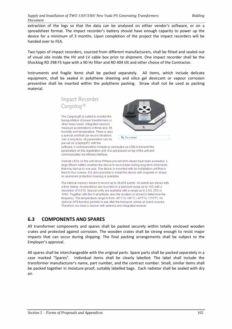
Supply and Installation of TWO 11kV/33kV New Vuda PS Generating Transformers Bidding
Document
Section 5 – Forms of Proposals and Appendices 102
extraction of the logs so that the data can be analysed on either vendor’s software, or on a spreadsheet format. The impact recorder’s battery should have enough capacity to power up the device for a minimum of 3 months. Upon completion of the project the impact recorders will be handed over to FEA. Two types of impact recorders, sourced from different manufacturers, shall be fitted and sealed out of visual site inside the HV and LV cable box prior to shipment. One impact recorder shall be the Shocklog RD 298 F5 type with a 90 Hz filter and RD 404 tilt and other choice of the Contractor. Instruments and fragile items shall be packed separately. All items, which include delicate equipment, shall be sealed in polythene sheeting and silica gel desiccant or vapour corrosion preventive shall be inserted within the polythene packing. Straw shall not be used as packing material.
6.3 COMPONENTS AND SPARES All transformer components and spares shall be packed securely within totally enclosed wooden crates and protected against corrosion. The wooden crates shall be strong enough to resist major impacts that can occur during shipping. The final packing arrangements shall be subject to the Employer’s approval.
All spares shall be interchangeable with the original parts. Spare parts shall be packed separately in a case marked "Spares". Individual items shall be clearly labelled. The label shall include the transformer manufacturer's name, part number, and the contract number. Small, similar items shall be packed together in moisture-proof, suitably labelled bags. Each radiator shall be sealed with dry air.

Supply and Installation of TWO 11kV/33kV New Vuda PS Generating Transformers Bidding
Document
Section 5 – Forms of Proposals and Appendices 103
6.4 Torque Wrench A Torque Wrench shall be supplied with each transformer to ensure all nuts and bolts can be tightened to their correct settings during site installation. A full list of all torque settings shall be provided in the Instruction Manual.
Supply and Installation of TWO 11kV/33kV New Vuda PS Generating Transformers Bidding
Document
Section 5 – Forms of Proposals and Appendices 104
Section 5 Form of Proposals and Appendices
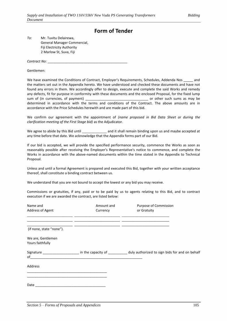
Supply and Installation of TWO 11kV/33kV New Vuda PS Generating Transformers Bidding
Document
Section 5 – Forms of Proposals and Appendices 105
Form of Tender To: Mr. Tuvitu Delairewa,
General Manager Commercial, Fiji Electricity Authority
2 Marlow St, Suva, Fiji Contract No: __________________________________________ Gentlemen: We have examined the Conditions of Contract, Employer's Requirements, Schedules, Addenda Nos _____ and the matters set out in the Appendix hereto. We have understood and checked these documents and have not found any errors in them. We accordingly offer to design, execute and complete the said Works and remedy any defects, fit for purpose in conformity with these documents and the enclosed Proposal, for the fixed lump sum of (in currencies, of payment) _________________________________ or other such sums as may be determined in accordance with the terms and conditions of the Contract. The above amounts are in accordance with the Price Schedules herewith and are made part of this bid. We confirm our agreement with the appointment of (name proposed in Bid Data Sheet or during the clarification meeting of the First Stage bid) as the Adjudicator. We agree to abide by this Bid until _____________ and it shall remain binding upon us and maybe accepted at any time before that date. We acknowledge that the Appendix forms part of our Bid. If our bid is accepted, we will provide the specified performance security, commence the Works as soon as reasonably possible after receiving the Employer's Representative's notice to commence, and complete the Works in accordance with the above-named documents within the time stated in the Appendix to Technical Proposal. Unless and until a formal Agreement is prepared and executed this Bid, together with your written acceptance thereof, shall constitute a binding contract between us. We understand that you are not bound to accept the lowest or any bid you may receive. Commissions or gratuities, if any, paid or to be paid by us to agents relating to this Bid, and to contract execution if we are awarded the contract, are listed below: Name and Amount and Purpose of Commission Address of Agent Currency or Gratuity ________________________ ________________________ _________________________ ________________________ ________________________ _________________________ ________________________ ________________________ _________________________ (if none, state “none”). We are, Gentlemen Yours faithfully Signature ___________________ in the capacity of __________ duly authorized to sign bids for and on behalf of___________________________________________________________ Address __________________________________________ __________________________________________ Date _____________________________________
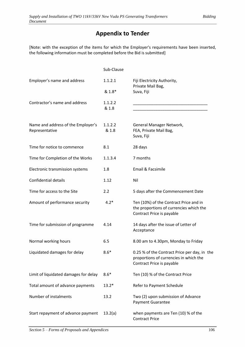
Supply and Installation of TWO 11kV/33kV New Vuda PS Generating Transformers Bidding
Document
Section 5 – Forms of Proposals and Appendices 106
Appendix to Tender
[Note: with the exception of the items for which the Employer's requirements have been inserted, the following information must be completed before the Bid is submitted]
Sub-Clause Employer’s name and address 1.1.2.1 Fiji Electricity Authority, Private Mail Bag, & 1.8* Suva, Fiji Contractor’s name and address 1.1.2.2 _________________________________ & 1.8 _________________________________ Name and address of the Employer’s 1.1.2.2 General Manager Network, Representative & 1.8 FEA, Private Mail Bag, Suva, Fiji Time for notice to commence 8.1 28 days Time for Completion of the Works 1.1.3.4 7 months Electronic transmission systems 1.8 Email & Facsimile Confidential details 1.12 Nil Time for access to the Site 2.2 5 days after the Commencement Date Amount of performance security 4.2* Ten (10%) of the Contract Price and in the proportions of currencies which the Contract Price is payable Time for submission of programme 4.14 14 days after the issue of Letter of Acceptance Normal working hours 6.5 8.00 am to 4.30pm, Monday to Friday Liquidated damages for delay 8.6* 0.25 % of the Contract Price per day, in the proportions of currencies in which the Contract Price is payable Limit of liquidated damages for delay 8.6* Ten (10) % of the Contract Price Total amount of advance payments 13.2* Refer to Payment Schedule Number of instalments 13.2 Two (2) upon submission of Advance Payment Guarantee Start repayment of advance payment 13.2(a) when payments are Ten (10) % of the Contract Price

Supply and Installation of TWO 11kV/33kV New Vuda PS Generating Transformers Bidding
Document
Section 5 – Forms of Proposals and Appendices 107
Repayment amortization of advance 13.2(b) 10% payment Percentage of retention 13.3(c)* TEN (10)% cash Retention Limit of Retention Money 13.3(c)* TEN (10)% of the Contract Price Minimum amount of Interim Payment 13.6* Five (5)% of the Contract Price Certificates If Sub-Clause 13.15 applies: Payments in Local and Foreign 1.1.5.3 Currencies & 13.15
Currency Unit Amount Payable in such Currency
Local: _____________________ [ name ] Foreign: ___________________ [ name ] ___________________ [ name ]
____________________ ____________________ ____________________
Amount of insurance for design 18.1 Full value of the Contract Price Amount of third party insurance 18.3 FJD 3,000,000 or contractor to propose Periods for submission of insurance: 18.5 (a) evidence of insurance * Not later than Commencement Date. (b) relevant policies * Fourteen (14) days after Commencement Date. Number of members of Dispute 20.3* Three (3) Adjudication Board Arbitration rules 20.6* International Chamber of Commerce, Rules of Arbitration Number of Arbitrators 20.6* Three (3) Language of arbitration 20.6* English Place of arbitration 20.6 Fiji Initials of signatory of Bid _____________________________________
Supply and Installation of TWO 11kV/33kV New Vuda PS Generating Transformers Bidding
Document
Section 7 – Schedules Part I – Schedule of Prices 108
Section 6 Sample Forms

Supply and Installation of TWO 11kV/33kV New Vuda PS Generating Transformers Bidding
Document
Section 7 – Schedules Part I – Schedule of Prices 109
Form of Contract Agreement
This Agreement made this _____ day of ____________ 20 _____ between _____________ _____________________________________________________________________________ of Fiji Electricity Authority (hereinafter called “the Employer") of the one part and_______________________________ of _______________________________________ (hereinafter called "the Contractor") of the other part Whereas the Employer desires that the Works known as Supply and Installation of Transformers should be designed and executed by the Contractor, and has accepted a Bid by the Contractor for the design, execution and completion of such Works and the remedying of any defects therein. The Employer and the Contractor agree as follows: 1. In this Agreement words and expressions shall have the same meanings as are respectively assigned to
them in the Conditions of Contract hereinafter referred to. 2. The following documents shall be deemed to form and be read and construed as part of this
Agreement:
(a) The Letter of Acceptance dated ____________ (b) The Employer's Requirements (c) The Addenda nos. ___________ (d) The Bid dated _______________ (e) The Conditions of Contract (Parts I and II) (f) The completed Schedules, and (g) The Contractor's Proposal.
3. In consideration of the payments to be made by the Employer to the Contractor as hereinafter mentioned, the Contractor hereby covenants with the Employer to design, execute and complete the Works and remedy any defects therein in conformity in all respects with the provisions of the Contract.
4. The Employer hereby covenants to pay the Contractor, in consideration of the design, execution and completion of the Works and the remedying of defects therein, the Contract Price or such other sum as may become payable under the provisions of the Contract at the times and in the manner prescribed by the Contract.
5. This Agreement shall come into effect on signing by both parties. In Witness whereof the parties hereto have caused this Agreement to be executed the day and year first before written in accordance with their respective laws.
Authorized signature of Contractor Authorized signature of Contractor SEAL SEAL (if any) (if any) in the presence of: in the presence of: Name ________________________ Name ______________________ Signature ______________________ Signature ____________________ Address _________________________ Address _______________________

Supply and Installation of TWO 11kV/33kV New Vuda PS Generating Transformers Bidding
Document
Section 7 – Schedules Part I – Schedule of Prices 110
Form of Performance Security (Bank Guarantee) To: Fiji Electricity Authority 2 Marlow st, Suva Fiji Tender Name: Design, manufacture transport, Supply and Installation of TWO X 11kV/33kV 15MVA Transformer for New Vuda Power Station Tender No: ___________ WHEREAS____________________________________ [name and address of Contractor] (hereinafter called "the Contractor") has undertaken, in pursuance of Contract No. ____________ dated ______ to execute _______________________________________ [name of Contract and brief description of Works] (hereinafter called "the Contract"); AND WHEREAS it has been stipulated by you in the said Contract that the Contractor shall furnish you with a Bank Guarantee by a recognized bank for the sum specified therein as security for compliance with its obligations in accordance with the Contract; AND WHEREAS we have agreed to give the Contractor such a Bank Guarantee; NOW THEREFORE we hereby affirm that we are the Guarantor and responsible to you, on behalf of the Contractor, up to a total of __________________________________ [amount of Guarantee] _______________________________________ [in words], such sum being payable in the types and proportions of currencies in which the Contract Price is payable, and we undertake to pay you, upon your first written demand and without cavil or argument, any sum or sums within the limits of ______________________________________ [amount of Guarantee] as aforesaid without your needing to prove or to show grounds or reasons for your demand for the sum specified therein. We hereby waive the necessity of your demanding the said debt from the Contractor before presenting us with the demand. We further agree that no change or addition to or other modification of the terms of the Contract or of the Works to be performed thereunder or of any of the Contract documents which may be made between you and the Contractor shall in any way release us from any liability under this guarantee, and we hereby waive notice of any such change, addition or modification. This guarantee shall be valid until the date of issue of the Performance Certificate.
Signature and Seal of the Guarantor ______________________________ Name of Bank ______________________________ Address ______________________________
Date ______________________________
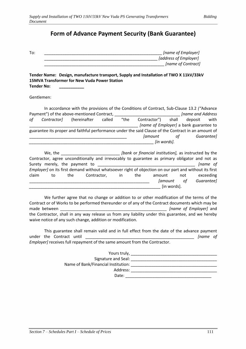
Supply and Installation of TWO 11kV/33kV New Vuda PS Generating Transformers Bidding
Document
Section 7 – Schedules Part I – Schedule of Prices 111
Form of Advance Payment Security (Bank Guarantee) To: ____________________________________________________ [name of Employer] __________________________________________________ [address of Employer] _____________________________________________________ [name of Contract] Tender Name: Design, manufacture transport, Supply and Installation of TWO X 11kV/33kV 15MVA Transformer for New Vuda Power Station Tender No: ___________ Gentlemen: In accordance with the provisions of the Conditions of Contract, Sub-Clause 13.2 (“Advance Payment") of the above-mentioned Contract, _____________________________ [name and Address of Contractor] (hereinafter called “the Contractor") shall deposit with ________________________________________________ [name of Employer] a bank guarantee to guarantee its proper and faithful performance under the said Clause of the Contract in an amount of ___________________________________________ [amount of Guarantee]
_______________________________________________________ [in words]. We, the __________________________ [bank or financial institution], as instructed by the Contractor, agree unconditionally and irrevocably to guarantee as primary obligator and not as Surety merely, the payment to ___________________________________________ [name of Employer] on its first demand without whatsoever right of objection on our part and without its first claim to the Contractor, in the amount not exceeding _____________________________________________________ [amount of Guarantee] __________________________________________________________ [in words]. We further agree that no change or addition to or other modification of the terms of the Contract or of Works to be performed thereunder or of any of the Contract documents which may be made between _______________________________________________ [name of Employer] and the Contractor, shall in any way release us from any liability under this guarantee, and we hereby waive notice of any such change, addition or modification. This guarantee shall remain valid and in full effect from the date of the advance payment under the Contract until ________________________________________________ [name of Employer] receives full repayment of the same amount from the Contractor.
Yours truly, ______________________________________ Signature and Seal: ______________________________________
Name of Bank/Financial Institution: ______________________________________ Address: ______________________________________
Date: ______________________________________

Supply and Installation of TWO 11kV/33kV New Vuda PS Generating Transformers Bidding
Document
Section 7 – Schedules Part I – Schedule of Prices 112
Section 7 Schedules - Part I Schedule of Prices

Supply and Installation of TWO 11kV/33kV New Vuda PS Generating Transformers Bidding
Document
Section 7 – Schedules Part I – Schedule of Prices 113
1 NOTES ON SCHEDULES The Schedules are intended to provide the Employer with essential supplementary information in an organized format. Examples of more commonly used Schedules are given herein. Others may be devised and added in accordance with the requirements of the Instructions to Bidders. All the Schedules are essential for bid evaluation and some in contract execution; they should all be incorporated in the Contract, and appropriate changes introduced with the approval of the Employer or its representative. The schedules are to be completed and submitted as part of the Tender submission in accordance with the Instructions to Bidders Clause 13, Documents Comprising the Bid.
2 SCHEDULE OF PRICES & CONDITIONS OF PAYMENT
2.1 CONTRACT PRICE The Contract Price is comprehensive in that, in consideration of the Contractor meeting all obligations, conditions and liabilities under the Contract, including the Contractor’s allowance for the cost of supply of all labour, materials, plant, supervision required to complete the Contract Works, overheads and profit, subject only such adjustment as is provided for the Contract.
2.2 BASIS OF SCHEDULES Descriptions of various items contained in the Schedule of Prices are intended to be a complete definition of the scope of the Contract Works, for which reference shall be made to the Specification, Drawings, Basis of Payments and other Contract Documents. The items descriptions on the Schedule of Prices shall be used only for the purpose of calculating progress payments and for valuing variations.
2.3 BASIS OF PAYMENTS The rate or cost of the items shall represent the total cost of designing (where appropriate), checking, approving, purchasing, constructing, installing, commissioning, training the Employer’s staff, testing and providing as-built drawings and O&M manuals for the works unless separate items have been included for some of these activities.
2.4 PAYMENTS TERMS All payments shall be due and payable by the Employer in accordance with the payments terms detailed below. The payments shall be made on completion of milestones as identified and agreed by both the Employer’s Representative and the Contractor.
Particulars Milestone Payment (% )
SUPPLY AND INSTALL NEW TRANSFORMER
1 Advance payment As per clause 13.2 of Section 3 - Conditions of Particular Application
10%
2 Delivery of Plant and Equipment to FEA site
Upon arrival of plant and equipment (DDU) to New Vuda Power Station
60%
3 Installation and commissioning of new transformers
Upon completion of commissioning, rectification of defects and issuing of performance certificate
20%
4 Retention 12 months after issuing of performance certificate 10%
TOTAL 100%
Note: The retention amount will be deducted from the total value of each payment made (Each invoice has to include the 10% retention deduction).
Supply and Installation of TWO 11kV/33kV New Vuda PS Generating Transformers Bidding
Document
Section 7 – Schedules Part I – Schedule of Prices 114
Offshore payment for all services provided on-shore (such as installation and commissioning) by the contractor is liable for taxation under the laws of Fiji. If the contractor is not a registered entity in Fiji, then a withholding tax of 15% will be levied by the Government of Fiji on all work carried out by the contractor related to installation and commissioning in Fiji. This amount will be deducted from the outward payments being made to the contractor. The contractor shall therefore specify in the price schedules whether the bid price is inclusive of the 15% withholding tax. Note that this will not be levied on the design, manufacture or supply of any plant or equipment.
3 SCHEDULES OF RATES & PRICES
3.1 NOTES ON SCHEDULES OF RATES AND PRICES 1. The Schedules are divided into seven separate sections as follows: 3.2 Plant and Equipment Including Mandatory Spare Parts 3.3 Installation and Other Services 3.4 Grand Summary 3.5 Alternative Offer 3.6 Bidders Tools & Equipment 3.7 Recommended Tools and Spare Parts 3.8 Rates for Variation
2. The Schedules do not generally give a full description of the plant and equipment to be supplied and the services to be performed under each item. Bidders shall be deemed to have read the Employer’s Requirements and other section of the bidding documents and reviewed the Drawings to ascertain the full scope of the requirements included in each item prior to filling in the rates and prices. The entered rate and prices shall be deemed to include for the full scope as aforesaid including overheads and profit.
3. Bid prices shall be quoted in the manner indicated and in the currencies specified in the Instructions to Bidders in the bidding documents. For each item, bidder shall complete each appropriate column in the respective Schedules, giving the price breakdown as indicated in the Schedules. Prices given in the Schedules against each item shall be for the scope covered by that item as detailed in the Employer’s Requirements, Drawings or elsewhere in the bidding documents.
4. Items left blank with be deemed to have been included in other items. The TOTAL for each Schedule and TOTAL of the Grand Summary shall be deemed to be the total price for executing the facilities and sections thereof in complete accordance with the Contract.
5. These schedules are intended primarily to provide information for bid evaluation but not intended to be used for the evaluation of work done for the purpose of interim payment. They may however, be used as a reference for the adjustment of the Schedule of Payment should the need arise.
6. These schedules can also be used as a basis to value variations of work done under the Proposal Sum.

Supply and Installation of Transformers Bidding Document
Section 7 – Schedules Part I – Schedule of Prices 115
3.2 PLANT AND EQUIPMENT INCLUDING MANDATORY SPARE PARTS
ITEM NO.
DESCRIPTION
ESTIMATE
DDU FIJI F/C
DDU FIJI FJD
LOCAL TRANSPORT & ERECTION ON SITE
FJD
TOTAL AMOUNT (Excluding Taxes &
Duties)
Qty Unit
Unit Rate
Amount Unit Rate
Amount Unit Rate
Amount F/C FJD
1 2 3 4=1 5=2+3
A NEW 11kV/33kV STEP-UP TRANSFORMER
A.1 11kV/33kV Generator Transformer, 15 MVA ONAN YNd 1, including MR off-load tap changer, freight, insurance and transportation to site 1 Nos.
A.2 Design Review – 1 FEA staff at the Factory
A.3 Witness testing by FEA staff (2) at the Factory for Factory Acceptance Witness testing
A.4 Mandatory Spares and other accessories 1 Set
A.5 Impact Recorders for transportation 5 Nos
TOTAL FOR PART A
3.3 INSTALLATION AND OTHER SERVICES
ITEM NO.
DESCRIPTION
ESTIMATE
F/C FJD TOTAL
AMOUNT (Including VAT)
Qty Unit Unit Total Unit Total F/C FJD
6 7 8=6 9=7
A NEW 11kV/33kV STEP-UP TRANSFORMER
A.1 Installation of new 11kV/33kV Transformer, 15 MVA ONAN YNd 1, together with tap changer, Qualitrol equipment and other accessories. 1 Nos
A.2 Site Testing and commissioning of the new transformer 1 Nos.
TOTAL FOR PART B
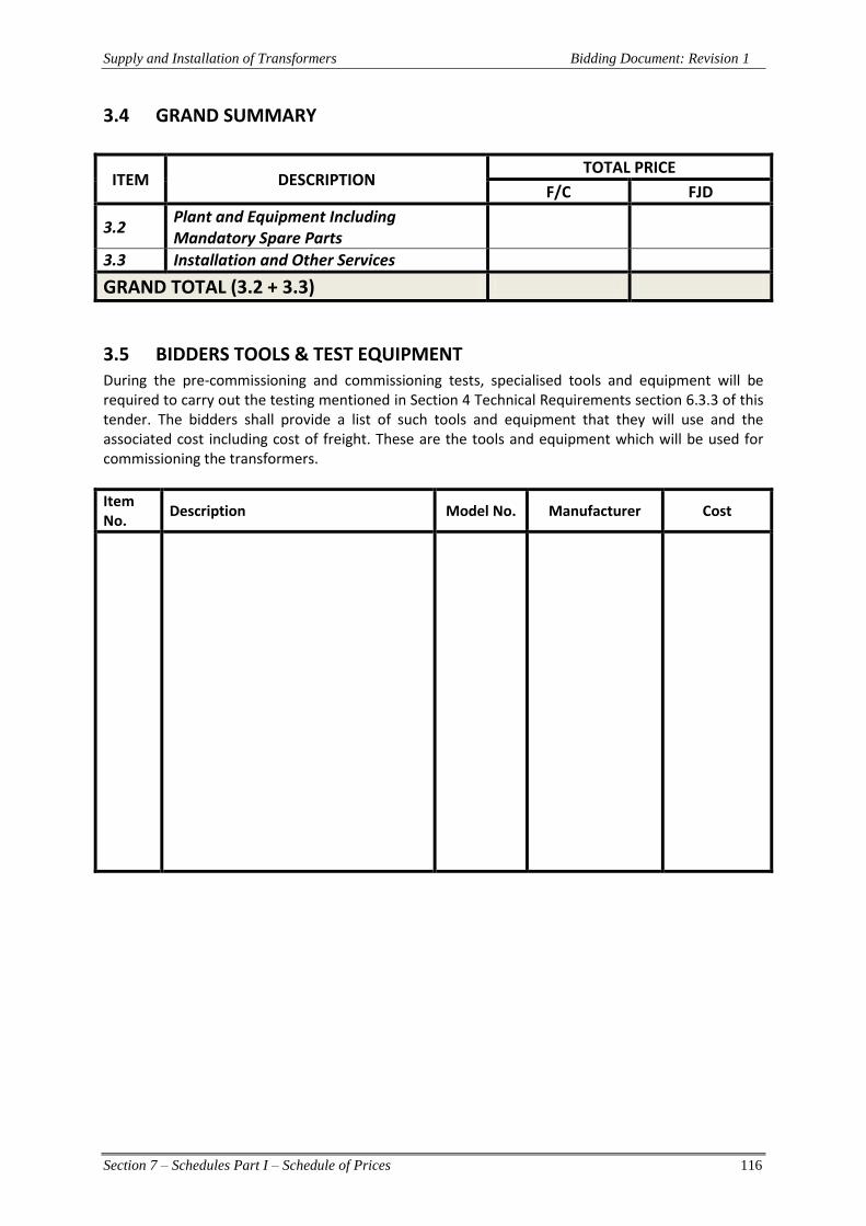
Supply and Installation of Transformers Bidding Document: Revision 1
Section 7 – Schedules Part I – Schedule of Prices 116
3.4 GRAND SUMMARY
ITEM DESCRIPTION TOTAL PRICE
F/C FJD
3.2 Plant and Equipment Including Mandatory Spare Parts
3.3 Installation and Other Services
GRAND TOTAL (3.2 + 3.3)
3.5 BIDDERS TOOLS & TEST EQUIPMENT During the pre-commissioning and commissioning tests, specialised tools and equipment will be required to carry out the testing mentioned in Section 4 Technical Requirements section 6.3.3 of this tender. The bidders shall provide a list of such tools and equipment that they will use and the associated cost including cost of freight. These are the tools and equipment which will be used for commissioning the transformers.
Item No.
Description Model No. Manufacturer Cost
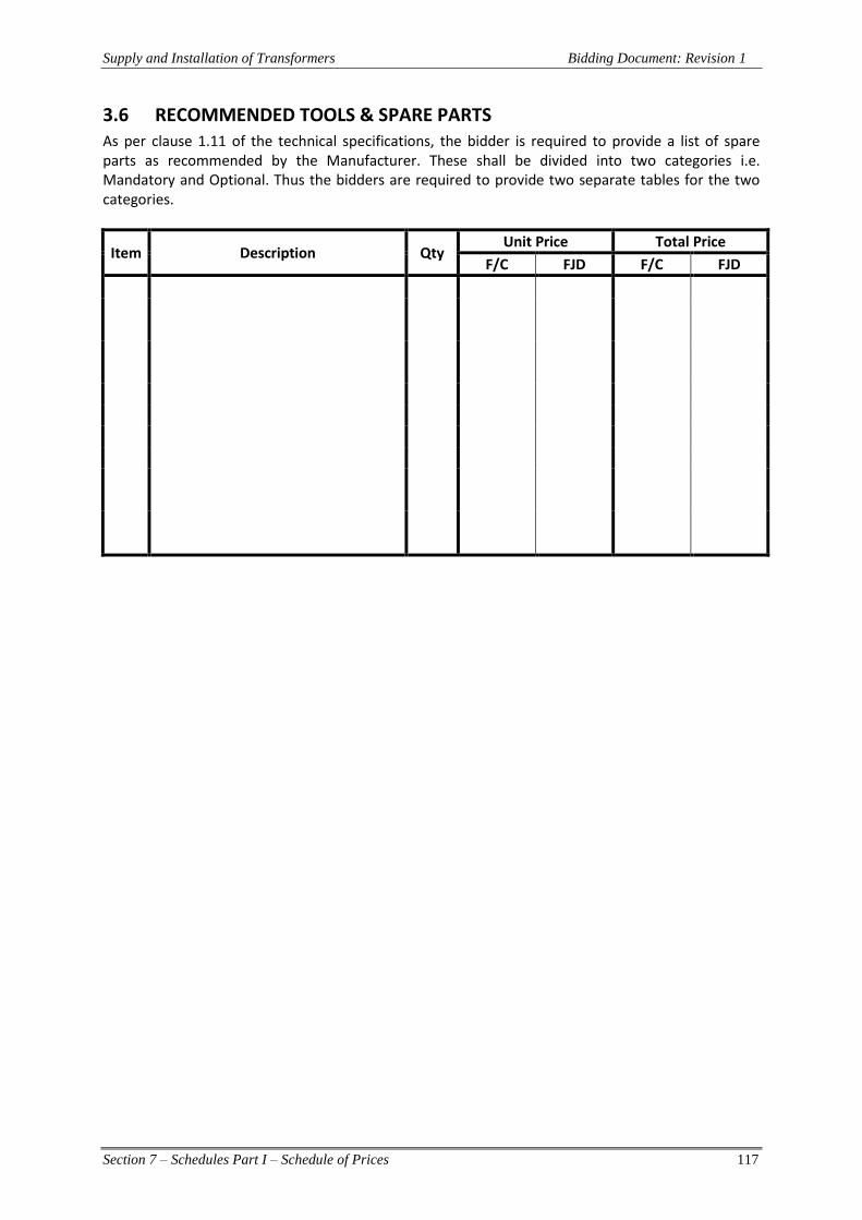
Supply and Installation of Transformers Bidding Document: Revision 1
Section 7 – Schedules Part I – Schedule of Prices 117
3.6 RECOMMENDED TOOLS & SPARE PARTS As per clause 1.11 of the technical specifications, the bidder is required to provide a list of spare parts as recommended by the Manufacturer. These shall be divided into two categories i.e. Mandatory and Optional. Thus the bidders are required to provide two separate tables for the two categories.
Item Description Qty Unit Price Total Price
F/C FJD F/C FJD

Supply and Installation of Transformers Bidding Document: Revision 1
Section 7 – Schedules Part I – Schedule of Prices 118
3.7 RATES FOR VARIATION The Contractor shall aim to carry out the project without any variations. However, if unforseen circumstances and event warrant any variation, the Contractor shall only proceed with a written approval from the Employer’s Representative. The agreed price variation shall be documented. The rates stated in this schedule shall be applicable to variations ordered by the Employer’s Representative and not covered by the Schedule of Prices. These rates shall be deemed to include the cost of construction facilities, professional and technical services, royalties, taxes, transport of equipment, labour and other changes necessary to perform the work. The Contractor shall not be entitled to any allowance above unit rates stated in the schedule by reason of any amount of work being required under such items during the currency of the Contract.
3.7.1 Materials
Materials required for variations or day work shall be paid for on the basis of the net quantities actually used in accordance with the Employer’s Representatives. Payment will be at the cost on site based on evidence of purchased prices after deductions of all trade and bulk discounts, transport, and any other charges applicable to the materials plus the percentage stated below to cover contractor’s profit and overheads. Materials supplied by the Contractor will be at prices to be agreed, due regard being paid to the prices for similar materials if supplied from outside sources.
3.7.2 Labour
Payment of labour shall be in accordance with the table of hourly rates below which shall include Contractor’s profit, overheads, superintendence, insurance, time keeping and all clerical and office work and use of hand operated tools and all incidental chargers whatsoever. The time of technicians or leading hands working with the crews will be paid for at rates stated but the time of the supervisors and foremen shall be covered by the overhead component of the hourly rates.
Item No.
Grade of Officer/Workman Rate/hour
F/C Rate/hour
FJD
% for Cost of Materials …………………………………..
Supply and Installation of Transformers Bidding Document: Revision 1
Section 7 – Schedules Part II – Schedule of Supplementary Information 119
Section 7 Schedules - Part II Schedule of Supplementary Information
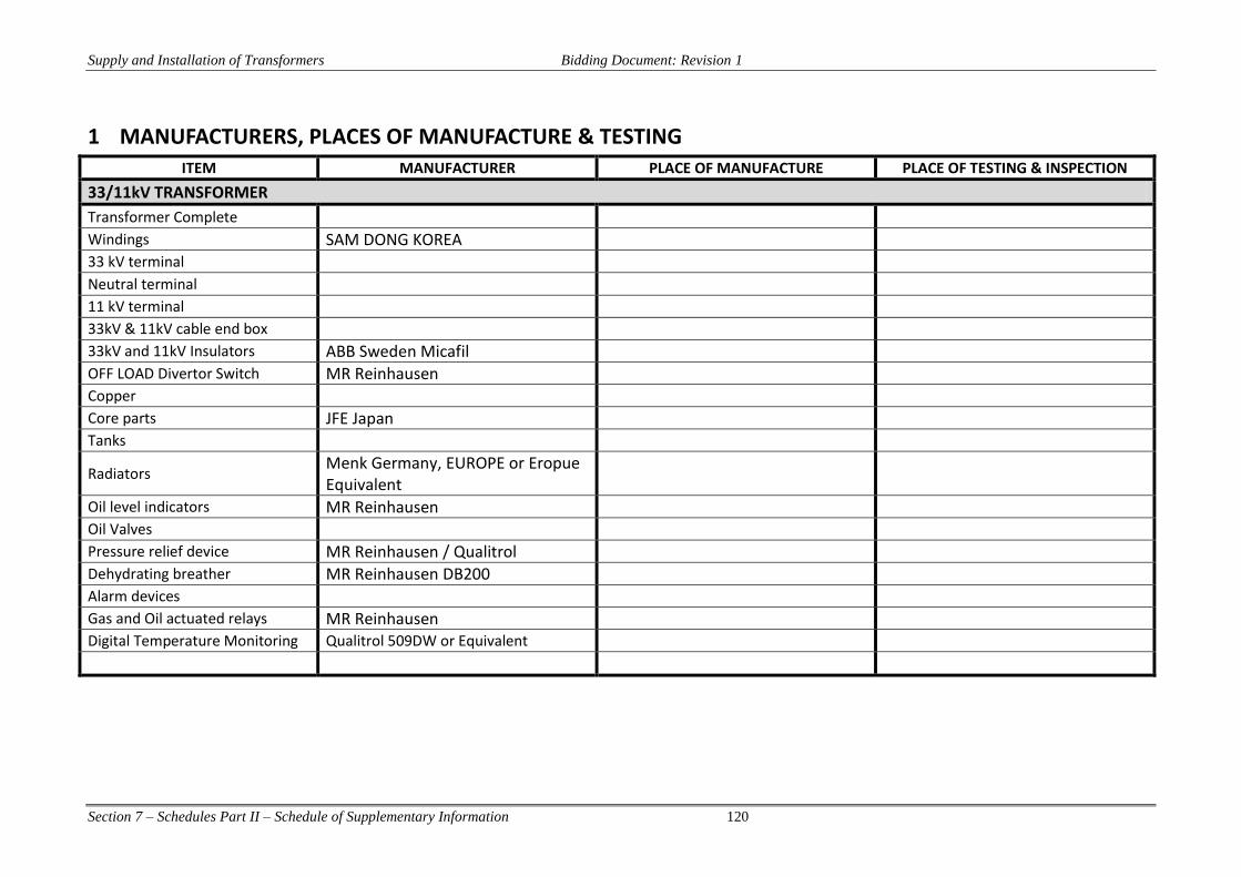
Supply and Installation of Transformers Bidding Document: Revision 1
Section 7 – Schedules Part II – Schedule of Supplementary Information 120
1 MANUFACTURERS, PLACES OF MANUFACTURE & TESTING ITEM MANUFACTURER PLACE OF MANUFACTURE PLACE OF TESTING & INSPECTION
33/11kV TRANSFORMER
Transformer Complete Windings SAM DONG KOREA 33 kV terminal Neutral terminal 11 kV terminal 33kV & 11kV cable end box 33kV and 11kV Insulators ABB Sweden Micafil OFF LOAD Divertor Switch MR Reinhausen Copper Core parts JFE Japan Tanks
Radiators Menk Germany, EUROPE or Eropue Equivalent
Oil level indicators MR Reinhausen Oil Valves Pressure relief device MR Reinhausen / Qualitrol Dehydrating breather MR Reinhausen DB200 Alarm devices Gas and Oil actuated relays MR Reinhausen Digital Temperature Monitoring Qualitrol 509DW or Equivalent

Supply and Installation of Transformers Bidding Document: Revision 1
Section 7 – Schedules Part II – Schedule of Supplementary Information 121
2 TECHNICAL PARTICULARS AND GURANTEES – ELECTRICAL WORKS
2.1 15MVA 33/11kV TRANSFORMER
Item Units Required Tendered
(a) RATING & PERFORMANCE 1. Manufacturer’s Name 2. Manufacturer’s Address 3. County of Manufacture 4. Type number
5.
Delivery and off-loading a. Transformer delivered to New Vuda PS b. Spares delivered to New Vuda PS c. Delivery effected on Date
6.
Type of Construction a. Type (core or shell) b. Number of limbs c. Type of Cooling
7. Anti- corrosion design classification Severe marine 8. Rated Power and continuous rating ONAN MVA 15 ONAF MVA 15
9.
Nominal rated voltage on principal tapping: a. HV kV r.m.s. b. LV kV r.m.s.
10. Vector Group YNd 1 11. Number of phases 3 12. Number of Windings 2

Supply and Installation of Transformers Bidding Document: Revision 1
Section 7 – Schedules Part II – Schedule of Supplementary Information 122
13. Applicable Standard – IEC 60076
14. System maximum voltage for both windings Um HV 36 kV LV 12 kV
15.
Termination Type a. HV b. LV c. Neutral
16. Insulation type HV Graded LV Uniform
17. Highest Voltage for equipment HV 36 kV MV 12 kV
18. Winding Insulation Level
HV 170 – 70 N 95 – 38 LV 95 – 38
19. Transformer Nominal ratio 11kV/33kV
20.
Short circuit withstand fault level at terminals of
36kV busbars kA 31.5 12kV busbars kA 31.5
21. Type of Cooling ONAN 22. External cooling medium Air forced (FAN)
23.
Service conditions : Altitude not exceeding M 300 Air temperature not exceeding oC 50 Average air temperature in any one year not exceeding
oC
In any one day oC 38 Average in one year oC 30
24. OFF-LOAD Tap Changer MR Reinhausen (A) Type
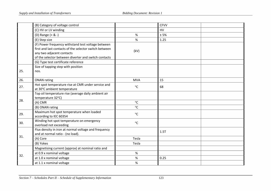
Supply and Installation of Transformers Bidding Document: Revision 1
Section 7 – Schedules Part II – Schedule of Supplementary Information 123
(B) Category of voltage control CFVV (C) HV or LV winding HV (D) Range (+ & -) % ± 5% (E) Step size % 1.25 (F) Power frequency withstand test voltage between first and last contacts of the selector switch between any two adjacent contacts of the selector between diverter and switch contacts
(kV)
(G) Type test certificate reference
25. Size of tapping step with position nos.
26. ONAN rating MVA 15
27. Hot spot temperature rise at CMR under service and at 30oC ambient temperature
oC 68
28.
Top oil temperature rise (average daily ambient air temperature 32oC)
(A) CMR oC (B) ONAN rating oC
29. Maximum hot spot temperature when loaded according to IEC 60354
oC
30. Winding hot spot temperature on emergency overload not exceeding
oC
31.
Flux density in iron at normal voltage and frequency and at normal ratio - (no load).
1.5T
(A) Core Tesla (B) Yokes Tesla
32.
Magnetising current (approx) at nominal ratio and at 0.9 x nominal voltage % at 1.0 x nominal voltage % 0.25 at 1.1 x nominal voltage %

Supply and Installation of Transformers Bidding Document: Revision 1
Section 7 – Schedules Part II – Schedule of Supplementary Information 124
at 1.2 x nominal voltage %
33.
Guaranteed Losses at nominal ratio (A) No Load losses kW (B) Copper losses at CMR kW (C) Auxiliary losses at CMR kW
34.
Regulation at 75oC and normal ratio - (A) At unity power factor % (B) At 0.8 lagging power factor %
35.
Impedance voltage at 75oC and CMR. Between HV and LV Windings at Tap
Maximum % Nominal % 7.00 Minimum %
36.
Equivalent circuit zero sequence impedance between HV and LV windings
Maximum Tap (1) Ω/phase Nominal Tap (6) Ω/phase Minimum Tap (16) Ω/phase
37.
Zero sequence impedance as a Percentage of Un 2IM Maximum Tap (1) % Nominal Tap (5) % Minimum Tap (8) %
38.
Maximum current density in windings at C.M.R. (A) HV Winding A/mm2 (B) LV Winding A/mm2
39.
Short circuit current that the transformer is designed to withstand, per unit (p.u.) of r.m.s. rated current
a. HV p.u. b. LV p.u.
40. No load loss of Principal tapping
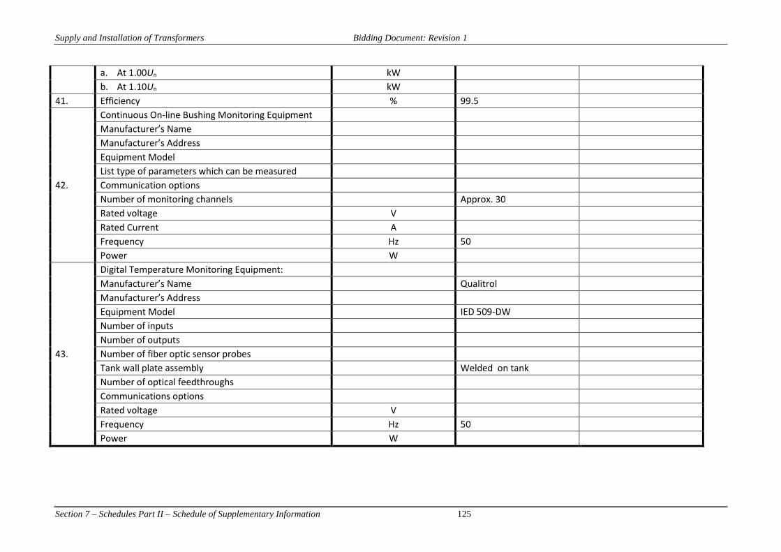
Supply and Installation of Transformers Bidding Document: Revision 1
Section 7 – Schedules Part II – Schedule of Supplementary Information 125
a. At 1.00Un kW b. At 1.10Un kW
41. Efficiency % 99.5
42.
Continuous On-line Bushing Monitoring Equipment Manufacturer’s Name Manufacturer’s Address Equipment Model List type of parameters which can be measured Communication options Number of monitoring channels Approx. 30 Rated voltage V Rated Current A Frequency Hz 50 Power W
43.
Digital Temperature Monitoring Equipment: Manufacturer’s Name Qualitrol Manufacturer’s Address Equipment Model IED 509-DW Number of inputs Number of outputs Number of fiber optic sensor probes Tank wall plate assembly Welded on tank Number of optical feedthroughs Communications options Rated voltage V Frequency Hz 50 Power W

Supply and Installation of Transformers Bidding Document: Revision 1
Section 7 – Schedules Part II – Schedule of Supplementary Information 126
Item Units Required Tendered
(b) CONTROL CIRCUITS
1. Type of controls for cooler
2. Whether automatic control required and the Yes reference voltage (VT output line to line) V 110 V AC 50 Hz
3. Whether load compensation required on the AVR. N/A
4. Whether separate remote control panel required No (use existing)
6.
DC supply (control voltage) : Nominal V 110 Maximum float voltage V 121
7. AC supply voltage for tap changer operating motor 3 phase.
415V
8. Whether provision for supervisory control required, including AVR setting
YES
9. Whether marshalling kiosk required YES
10. Number of transformers for which automatic control is to be provided
All
11.
Transformer terminals for line and neutral (i) HV line Cable box (ii) Neutral Cable box (iii) LV line Cable box
12. Accommodation of tank for outdoor weatherproof HV neutral current transformers
YES
13. Pollution category of bushings High-53.7mm/kV based on system highest voltage
mm/kV 53.7
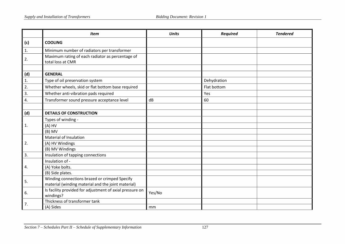
Supply and Installation of Transformers Bidding Document: Revision 1
Section 7 – Schedules Part II – Schedule of Supplementary Information 127
Item Units Required Tendered
(c) COOLING
1. Minimum number of radiators per transformer
2. Maximum rating of each radiator as percentage of total loss at CMR
(d) GENERAL
1. Type of oil preservation system Dehydration
2. Whether wheels, skid or flat bottom base required Flat bottom
3. Whether anti-vibration pads required Yes
4. Transformer sound pressure acceptance level dB 60
(d) DETAILS OF CONSTRUCTION
1.
Types of winding -
(A) HV
(B) MV
2.
Material of Insulation
(A) HV Windings
(B) MV Windings
3. Insulation of tapping connections
4.
Insulation of -
(A) Yoke bolts.
(B) Side plates.
5. Winding connections brazed or crimped Specify material (winding material and the joint material)
6. Is facility provided for adjustment of axial pressure on windings?
Yes/No
7. Thickness of transformer tank
(A) Sides mm
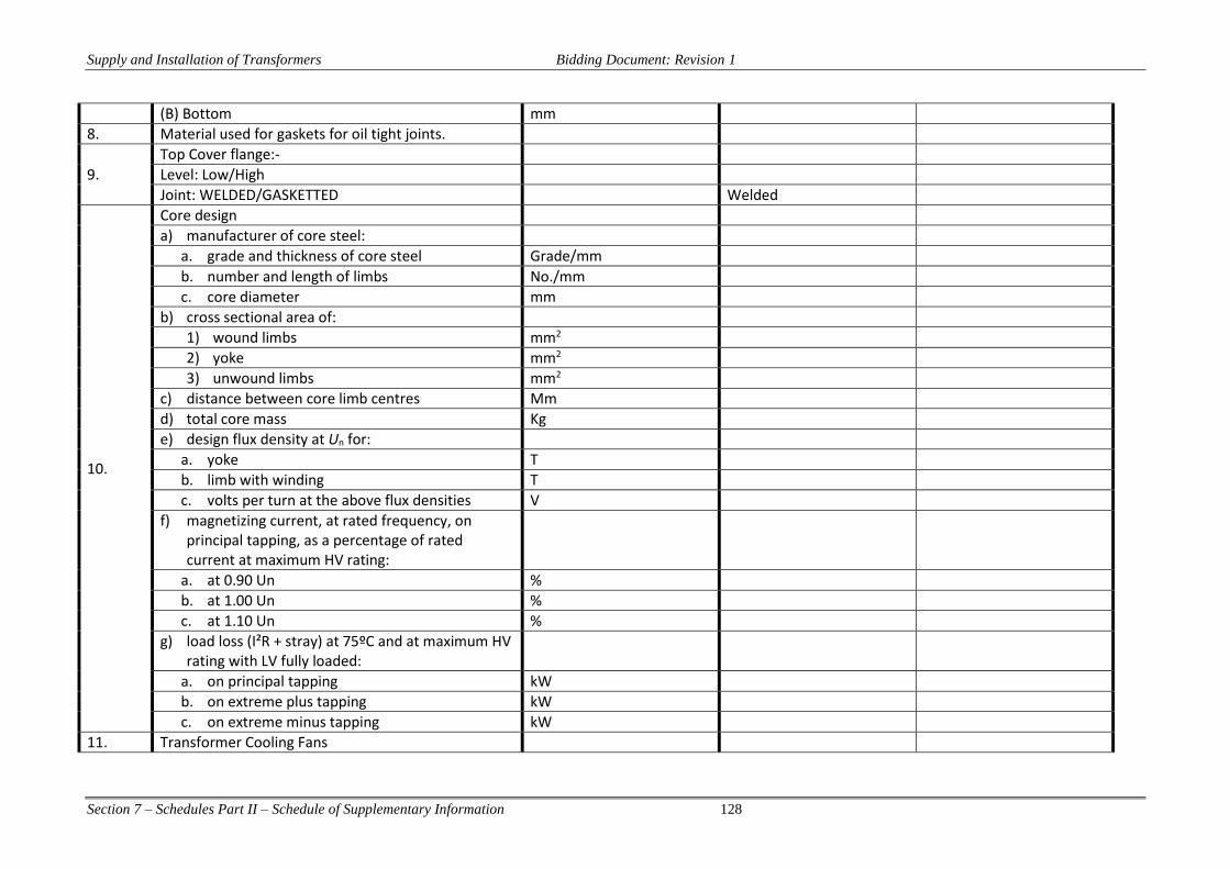
Supply and Installation of Transformers Bidding Document: Revision 1
Section 7 – Schedules Part II – Schedule of Supplementary Information 128
(B) Bottom mm
8. Material used for gaskets for oil tight joints.
9.
Top Cover flange:-
Level: Low/High
Joint: WELDED/GASKETTED Welded
10.
Core design
a) manufacturer of core steel:
a. grade and thickness of core steel Grade/mm
b. number and length of limbs No./mm
c. core diameter mm
b) cross sectional area of:
1) wound limbs mm2
2) yoke mm2
3) unwound limbs mm2
c) distance between core limb centres Mm
d) total core mass Kg
e) design flux density at Un for:
a. yoke T
b. limb with winding T
c. volts per turn at the above flux densities V
f) magnetizing current, at rated frequency, on principal tapping, as a percentage of rated current at maximum HV rating:
a. at 0.90 Un %
b. at 1.00 Un %
c. at 1.10 Un %
g) load loss (I²R + stray) at 75ºC and at maximum HV rating with LV fully loaded:
a. on principal tapping kW
b. on extreme plus tapping kW
c. on extreme minus tapping kW
11. Transformer Cooling Fans
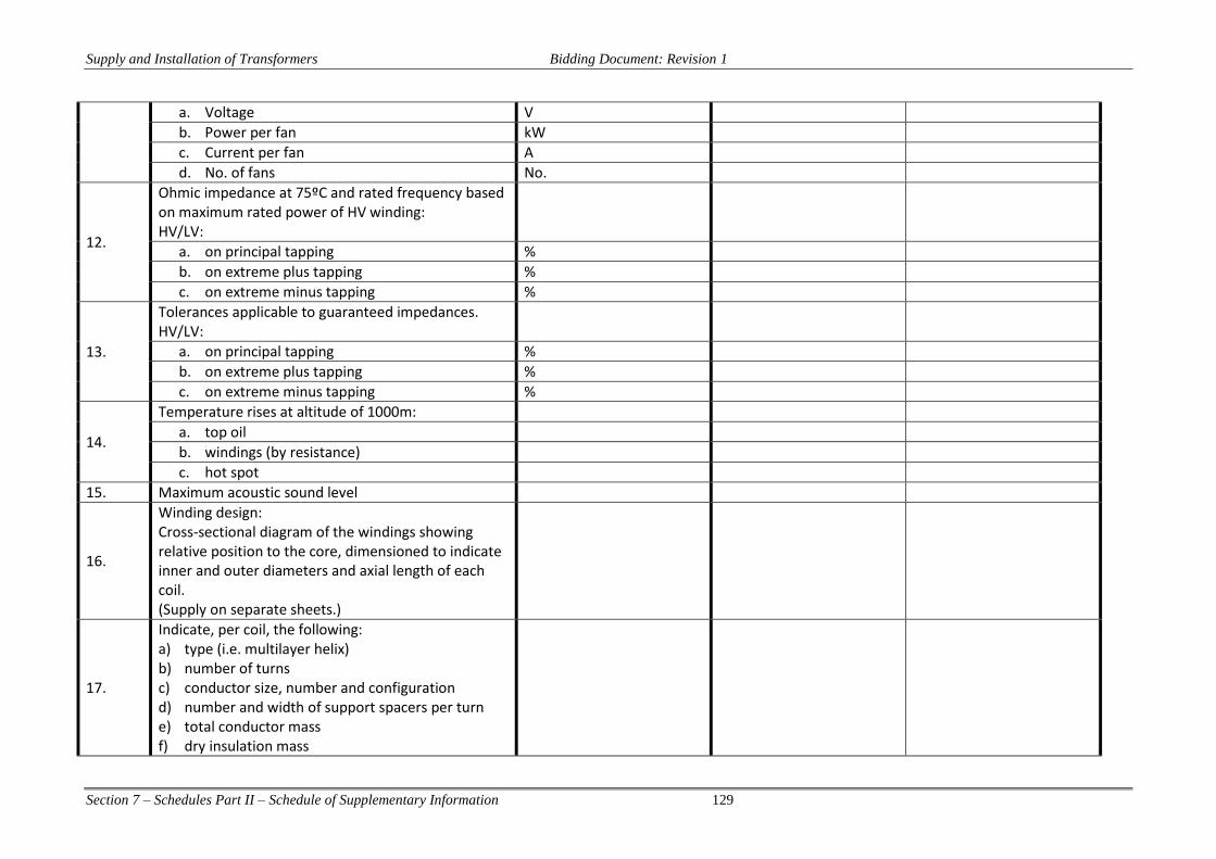
Supply and Installation of Transformers Bidding Document: Revision 1
Section 7 – Schedules Part II – Schedule of Supplementary Information 129
a. Voltage V
b. Power per fan kW
c. Current per fan A
d. No. of fans No.
12.
Ohmic impedance at 75ºC and rated frequency based on maximum rated power of HV winding: HV/LV:
a. on principal tapping %
b. on extreme plus tapping %
c. on extreme minus tapping %
13.
Tolerances applicable to guaranteed impedances. HV/LV:
a. on principal tapping %
b. on extreme plus tapping %
c. on extreme minus tapping %
14.
Temperature rises at altitude of 1000m:
a. top oil
b. windings (by resistance)
c. hot spot
15. Maximum acoustic sound level
16.
Winding design: Cross-sectional diagram of the windings showing relative position to the core, dimensioned to indicate inner and outer diameters and axial length of each coil. (Supply on separate sheets.)
17.
Indicate, per coil, the following: a) type (i.e. multilayer helix) b) number of turns c) conductor size, number and configuration d) number and width of support spacers per turn e) total conductor mass f) dry insulation mass

Supply and Installation of Transformers Bidding Document: Revision 1
Section 7 – Schedules Part II – Schedule of Supplementary Information 130
18.
Give details of processing of the active part (core and windings) making reference to temperatures, time, vacuum levels and clamping pressures. Include sizing of windings as part of the processing. (Supply on separate sheets.)
19. Impulse withstand test voltage for: a) HV b) LV
20. Sixty-second, separate source: a) HV b) LV
21.
Induced over voltage withstand test voltages: a) HV to earth b) LV to earth c) between terminals HV to HV d) between terminals LV to LV e) test frequency f) test duration
22.
Impulse withstand test voltage of main terminal bushings at sea level (1.2/50μs): a) HV b) LV c) LV Neutral
23.
Sixty-second, power-frequency withstand test voltage to earth: a) HV b) LV c) LV Neutral
24.
Total creepage distance: a) HV b) LV c) LV Neutral
25. Protected creepage distance:
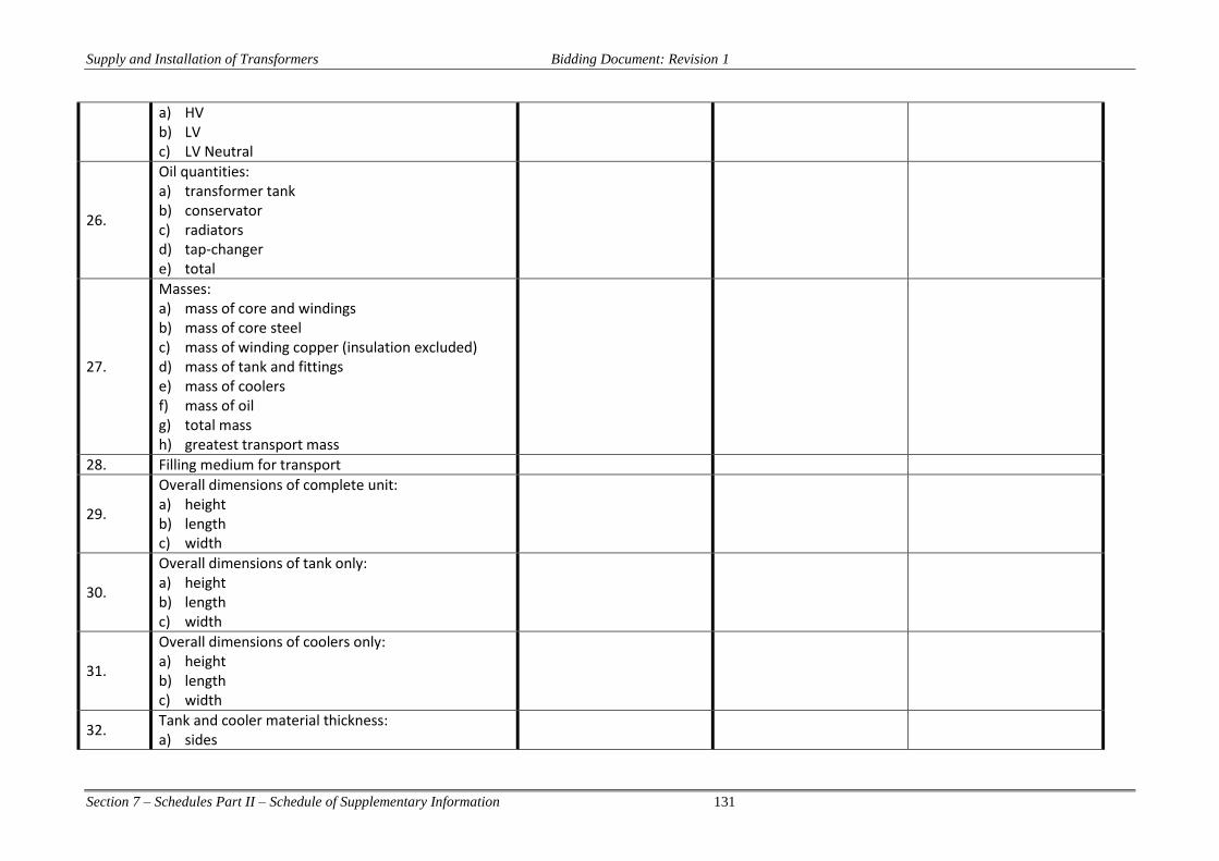
Supply and Installation of Transformers Bidding Document: Revision 1
Section 7 – Schedules Part II – Schedule of Supplementary Information 131
a) HV b) LV c) LV Neutral
26.
Oil quantities: a) transformer tank b) conservator c) radiators d) tap-changer e) total
27.
Masses: a) mass of core and windings b) mass of core steel c) mass of winding copper (insulation excluded) d) mass of tank and fittings e) mass of coolers f) mass of oil g) total mass h) greatest transport mass
28. Filling medium for transport
29.
Overall dimensions of complete unit: a) height b) length c) width
30.
Overall dimensions of tank only: a) height b) length c) width
31.
Overall dimensions of coolers only: a) height b) length c) width
32. Tank and cooler material thickness: a) sides

Supply and Installation of Transformers Bidding Document: Revision 1
Section 7 – Schedules Part II – Schedule of Supplementary Information 132
b) bottom c) top d) conservator e) cooler tubes f) pressed-sheet radiators
33. Safe withstand vacuum at sea level
34.
Bushings type, ratings and dimensions (attach data sheets): a) HV b) LV c) HV/LV/Neutral
35. Fan Motors: a) make b) type
36. Nominal 50 Hz ratings of tap-changer: a) voltage b) current
37.
Lightning impulse insulation level (1.2/50 μs full wave) of tap-changer: a) phase-to-ground b) phase-to-ground
38. Tap-changer 50 Hz insulation level withstand: a) phase-to-ground b) phase-to-phase
39.
Nominal voltage and current rating of tap-changer contacts: a) selector b) selector switch c) diverter switch
Nominal voltage and current rating of tap-changer transition resistor
40. Tap-changer driving motor: a) type of driving motor

Supply and Installation of Transformers Bidding Document: Revision 1
Section 7 – Schedules Part II – Schedule of Supplementary Information 133
b) power c) voltage d) current
41.
Resulting no-load voltage appearing: a) on principal tapping b) on extreme plus tapping c) on extreme minus tapping
42.
Have type test certificates been submitted with the tender for approval? If no, it will be assumed that no type tests for identical units are available.
43.
Actual maximum overall dimensions of the transformer (including surge arresters and their mounting brackets): a) height b) length c) width
44.
Guaranteed loss values: a) no load current with rated voltage on secondary
winding b) no-load loss at rated voltage c) load loss at ONAN rating
7kW 8kW 40kW
45. Are there any limitations in the performance of the required tests? If yes, state limitations
Item Units Required Tendered
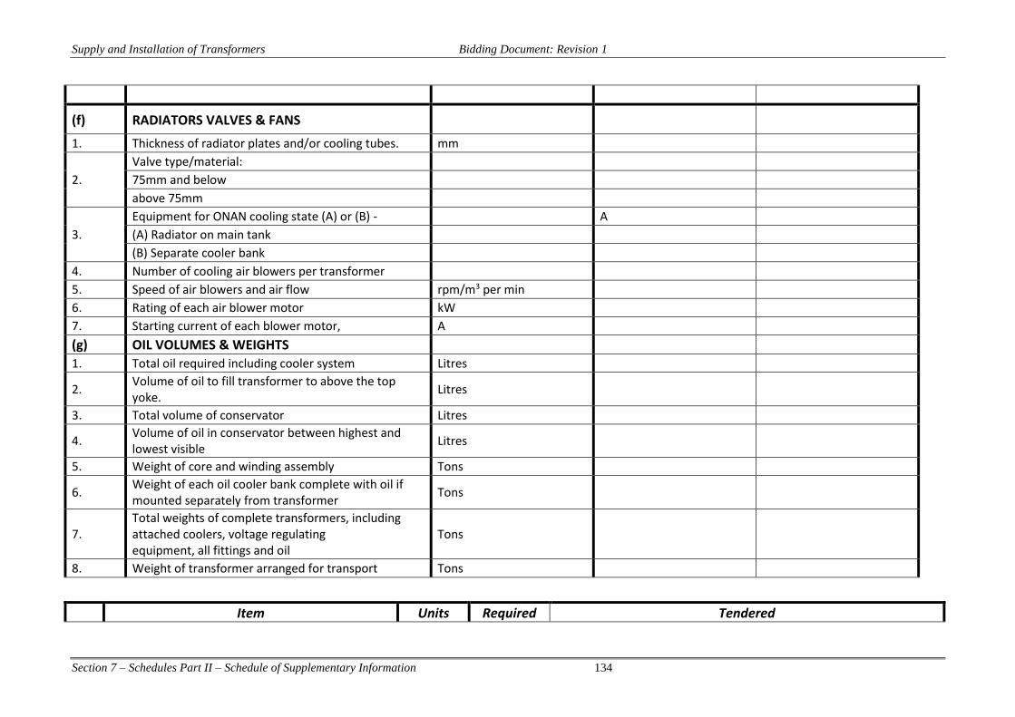
Supply and Installation of Transformers Bidding Document: Revision 1
Section 7 – Schedules Part II – Schedule of Supplementary Information 134
(f) RADIATORS VALVES & FANS
1. Thickness of radiator plates and/or cooling tubes. mm
2.
Valve type/material: 75mm and below above 75mm
3.
Equipment for ONAN cooling state (A) or (B) - A (A) Radiator on main tank (B) Separate cooler bank
4. Number of cooling air blowers per transformer 5. Speed of air blowers and air flow rpm/m3 per min 6. Rating of each air blower motor kW 7. Starting current of each blower motor, A
(g) OIL VOLUMES & WEIGHTS
1. Total oil required including cooler system Litres
2. Volume of oil to fill transformer to above the top yoke.
Litres
3. Total volume of conservator Litres
4. Volume of oil in conservator between highest and lowest visible
Litres
5. Weight of core and winding assembly Tons
6. Weight of each oil cooler bank complete with oil if mounted separately from transformer
Tons
7. Total weights of complete transformers, including attached coolers, voltage regulating equipment, all fittings and oil
Tons
8. Weight of transformer arranged for transport Tons
Item Units Required Tendered
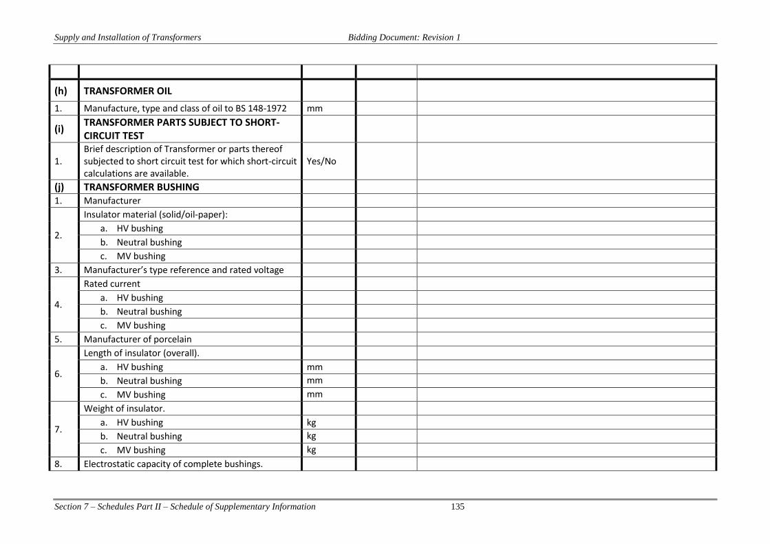
Supply and Installation of Transformers Bidding Document: Revision 1
Section 7 – Schedules Part II – Schedule of Supplementary Information 135
(h) TRANSFORMER OIL
1. Manufacture, type and class of oil to BS 148-1972 mm
(i) TRANSFORMER PARTS SUBJECT TO SHORT-CIRCUIT TEST
1. Brief description of Transformer or parts thereof subjected to short circuit test for which short-circuit calculations are available.
Yes/No
(j) TRANSFORMER BUSHING 1. Manufacturer
2.
Insulator material (solid/oil-paper): a. HV bushing b. Neutral bushing c. MV bushing
3. Manufacturer’s type reference and rated voltage
4.
Rated current a. HV bushing b. Neutral bushing c. MV bushing
5. Manufacturer of porcelain
6.
Length of insulator (overall). a. HV bushing mm b. Neutral bushing mm c. MV bushing mm
7.
Weight of insulator. a. HV bushing kg b. Neutral bushing kg c. MV bushing kg
8. Electrostatic capacity of complete bushings.

Supply and Installation of Transformers Bidding Document: Revision 1
Section 7 – Schedules Part II – Schedule of Supplementary Information 136
a. HV bushing pF b. Neutral bushing pF c. MV bushing pF
9.
Dry lightning impulse voltage withstand. (1.2/50 wave)
a. HV bushing kV b. Neutral bushing kV c. MV bushing kV
10.
50Hz dry voltage withstand a. HV bushing kV b. Neutral bushing kV c. MV bushing kV
11.
50Hz wet withstand voltage without arcing horns a. HV bushing kV b. Neutral bushing kV c. MV bushing kV
12.
Total creepage distance of shed (specified minimum 25mm/kV based on maximum system voltage)
a. HV bushing mm b. Neutral bushing mm c. MV bushing mm
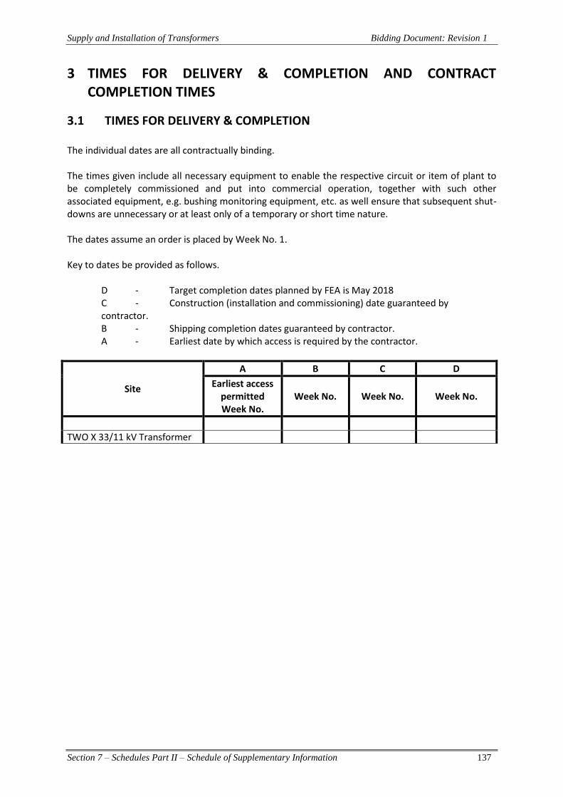
Supply and Installation of Transformers Bidding Document: Revision 1
Section 7 – Schedules Part II – Schedule of Supplementary Information 137
3 TIMES FOR DELIVERY & COMPLETION AND CONTRACT COMPLETION TIMES
3.1 TIMES FOR DELIVERY & COMPLETION The individual dates are all contractually binding. The times given include all necessary equipment to enable the respective circuit or item of plant to be completely commissioned and put into commercial operation, together with such other associated equipment, e.g. bushing monitoring equipment, etc. as well ensure that subsequent shut-downs are unnecessary or at least only of a temporary or short time nature. The dates assume an order is placed by Week No. 1. Key to dates be provided as follows.
D - Target completion dates planned by FEA is May 2018 C - Construction (installation and commissioning) date guaranteed by contractor. B - Shipping completion dates guaranteed by contractor. A - Earliest date by which access is required by the contractor.
Site
A B C D
Earliest access permitted Week No.
Week No. Week No. Week No.
TWO X 33/11 kV Transformer
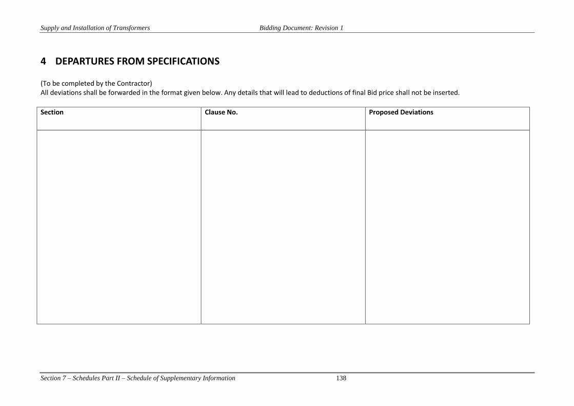
Supply and Installation of Transformers Bidding Document: Revision 1
Section 7 – Schedules Part II – Schedule of Supplementary Information 138
4 DEPARTURES FROM SPECIFICATIONS (To be completed by the Contractor) All deviations shall be forwarded in the format given below. Any details that will lead to deductions of final Bid price shall not be inserted.
Section Clause No. Proposed Deviations

Supply and Installation of Transformers Bidding Document: Revision 1
Section 7 – Schedules Part II – Schedule of Supplementary Information 139
5 MANUFACTURERS’ STATEMENT OF EXPERIENCE Bidders are to complete this schedule giving details of substation contract of the same type of construction as this contract and which they have completed or which are in the course of completion by them.
Country
System Voltage kV
Type of Construction
Employer
Consultant
Capacity of Power Transformer (MVA)
Contract Award Date
Contractual Completion Date
Actual Completion Date
Contract Value
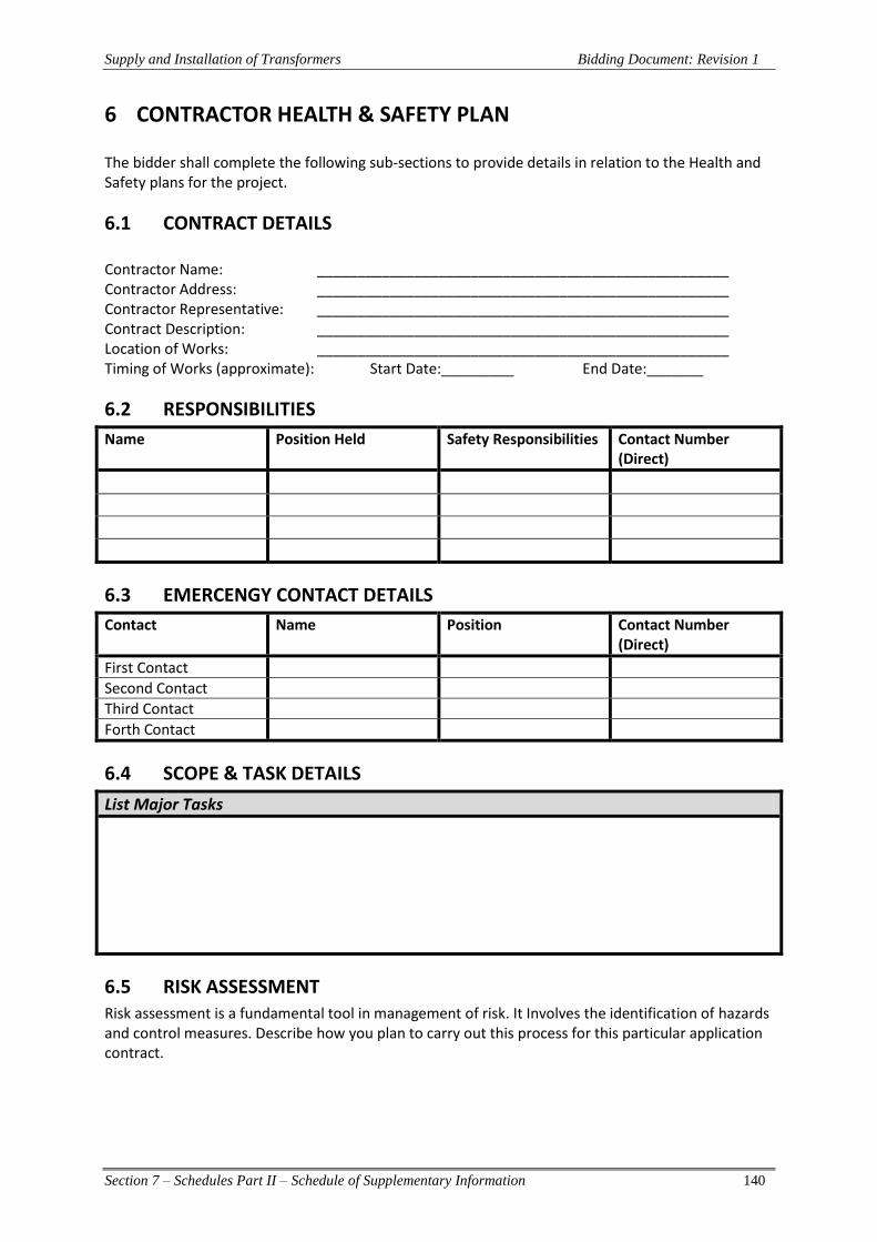
Supply and Installation of Transformers Bidding Document: Revision 1
Section 7 – Schedules Part II – Schedule of Supplementary Information 140
6 CONTRACTOR HEALTH & SAFETY PLAN The bidder shall complete the following sub-sections to provide details in relation to the Health and Safety plans for the project.
6.1 CONTRACT DETAILS Contractor Name: ___________________________________________________ Contractor Address: ___________________________________________________ Contractor Representative: ___________________________________________________ Contract Description: ___________________________________________________ Location of Works: ___________________________________________________ Timing of Works (approximate): Start Date:_________ End Date:_______
6.2 RESPONSIBILITIES
Name Position Held Safety Responsibilities Contact Number (Direct)
6.3 EMERCENGY CONTACT DETAILS
Contact Name Position Contact Number (Direct)
First Contact
Second Contact
Third Contact
Forth Contact
6.4 SCOPE & TASK DETAILS
List Major Tasks
6.5 RISK ASSESSMENT Risk assessment is a fundamental tool in management of risk. It Involves the identification of hazards and control measures. Describe how you plan to carry out this process for this particular application contract.

Supply and Installation of Transformers Bidding Document: Revision 1
Section 7 – Schedules Part II – Schedule of Supplementary Information 141
6.6 SAFE WORK PROCEDURES After completing the risk assessment, you must compile a safe system of work describing how you plan to control the hazards you have identified. Complete the following section outlining how you will ensure that all employees and subcontractors understand the Safe Work Procedures (SWP). Also attach copies of the relevant SWP.
6.7 PERSONAL PROTECTIVE EQUIPMENT Where risk assessment identifies the need for personal protective equipment (PPE), then PPE must be made available. List down below the PPE you will require for this project.
6.8 ACCESSING SITE/TIMES OF WORK If work is going to be carried out at FEA premises, then it is important to determine when you will be accessing the Site. You may need to sign a PASS and sign in and out. This will avoid conflicts with other activities which may be continuing on site during contract works. Describe below your site access requirements.
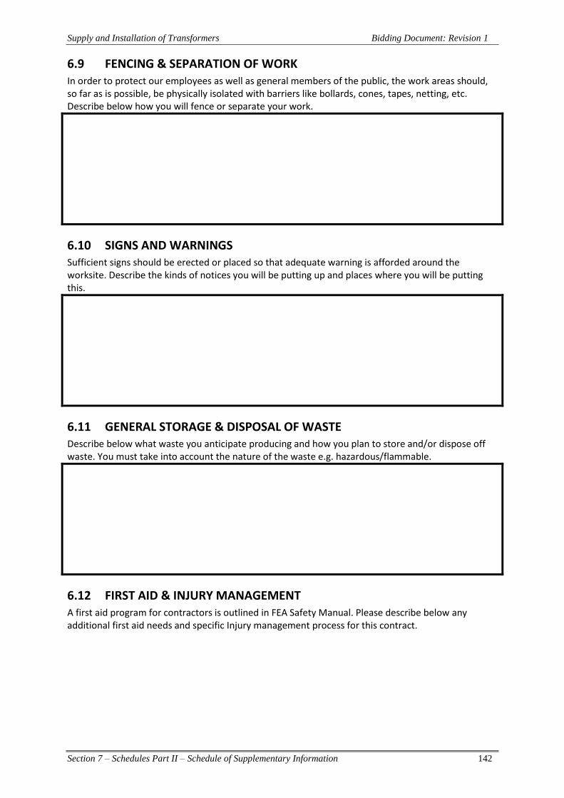
Supply and Installation of Transformers Bidding Document: Revision 1
Section 7 – Schedules Part II – Schedule of Supplementary Information 142
6.9 FENCING & SEPARATION OF WORK In order to protect our employees as well as general members of the public, the work areas should, so far as is possible, be physically isolated with barriers like bollards, cones, tapes, netting, etc. Describe below how you will fence or separate your work.
6.10 SIGNS AND WARNINGS Sufficient signs should be erected or placed so that adequate warning is afforded around the worksite. Describe the kinds of notices you will be putting up and places where you will be putting this.
6.11 GENERAL STORAGE & DISPOSAL OF WASTE Describe below what waste you anticipate producing and how you plan to store and/or dispose off waste. You must take into account the nature of the waste e.g. hazardous/flammable.
6.12 FIRST AID & INJURY MANAGEMENT A first aid program for contractors is outlined in FEA Safety Manual. Please describe below any additional first aid needs and specific Injury management process for this contract.

Supply and Installation of Transformers Bidding Document: Revision 1
Section 7 – Schedules Part II – Schedule of Supplementary Information 143
6.13 EMERGENCY PROCEDURES Identify specific emergency procedures or equipment required for the contract.
6.14 INCIDENT REPORTING & INVESTIGATION Describe how incidents will be reported and investigated during the contract.
6.15 SPECIALISED WORK OR LICENSING List any special licences required for the contract.
6.16 TRAINING & INDUCTION REQUIREMENTS Training and inductions for contractors are to be completed in accordance with the FEA Training requirements. List any training required for the contract works in relation to safety, for example safe procedure training and attach training certificates:
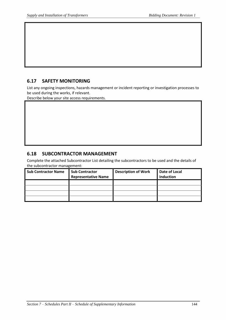
Supply and Installation of Transformers Bidding Document: Revision 1
Section 7 – Schedules Part II – Schedule of Supplementary Information 144
6.17 SAFETY MONITORING List any ongoing inspections, hazards management or incident reporting or investigation processes to be used during the works, if relevant. Describe below your site access requirements.
6.18 SUBCONTRACTOR MANAGEMENT Complete the attached Subcontractor List detailing the subcontractors to be used and the details of the subcontractor management:
Sub Contractor Name Sub Contractor Representative Name
Description of Work Date of Local Induction
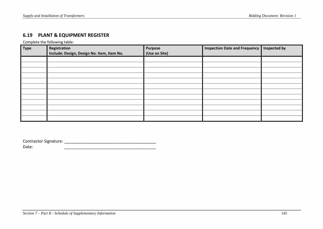
Supply and Installation of Transformers Bidding Document: Revision 1
Section 7 – Part II - Schedule of Supplementary Information 145
6.19 PLANT & EQUIPMENT REGISTER Complete the following table:
Type Registration Include: Design, Design No. Item, Item No.
Purpose (Use on Site)
Inspection Date and Frequency Inspected by
Contractor Signature: ________________________________________ Date: ________________________________________

Supply and Installation of Transformers Bidding Document: Revision 1
Section 7 – Part II - Schedule of Supplementary Information 146
6.20 CONTRACTOR CHEMICAL REGISTER Complete the following table:
Product Name Hazard Controls Required Location Quantity
Contractor Signature: ________________________________________ Date: ________________________________________

Supply and Installation of Transformers Bidding Document: Revision 1
Section 7 – Part II - Schedule of Supplementary Information 147
7 OTHER DOCUMENTS & DRAWINGS TO BE SUBMITTED WITH BID As a minimum requirement to be considered for technical evaluation, the following documents & drawings shall be submitted with the Bid: 7.1 Typical plan and section drawings of transformer 7.2 Foundation drawings of transformer 7.3 Manufactures Technical Broachers type number, reference number and Drawings showing
details of construction and dimensions of :- a) Power Transformers. b) Bushings (33kV and 11kV)
7.4 Typical arrangement drawing of transformer marshalling kiosk. 7.5 Control and wiring drawings of auxiliary relays (transformer temperature monitor,
bushing monitor, oil and gas relays, etc). 7.6 Cross section drawings of transformer terminal boxes and terminal sealing ends. 7.7 Independent type test certificates for,
a) Power Transformers. 7.8 General bar chart of the design, manufacturing, shipping, erection and commissioning
schedule clearly showing the dated. 7.9 Evidence of Bidder’s experience in works similar to this. 7.10 Evidence of Bidder’s subcontractor’s experience in works similar to those
subcontracted. 7.11 Certificates issued by an independent International Organization to ensure compliance
with the ISO 9001:2000 standards by Bidder and manufacturers. 7.12 List of standards the Bidder intends to follow for the electrical works. 7.13 Evidence of Manufacturer’s experience in manufacturing comparable type of equipment
or equivalent as offered under this contract. 7.14 Descriptive information for equipment being offered including:
a) List of recommended spare parts with prices. b) List of special tools or fixtures required for installation, testing, maintaining and
operating the equipment c) List and cost of special tools, lifting devices required for installation, operation
and maintenance. d) List of exceptions to and deviations from this specification. All exceptions shall be
clarified and separately itemized. It shall not be necessary for the employer to examine the standard literature and documents of the manufacturer to determine the existence and extent of any exceptions or deviations from this specification.
e) Evidence of field service experience of main equipment.
Tender Submission - Instruction to bidders

Supply and Installation of Transformers Bidding Document: Revision 1
Section 7 – Part II - Schedule of Supplementary Information 148
It is mandatory for Bidders to upload a copy of their bid in the TENDER LINK Electronic Tender Box no later than 4:00pm, on Wednesday 25th October, 2017 To register your interest and tender a response, view 'Current Tenders' at: https://www.tenderlink.com/fea For further information contact The Secretary Tender Committee, by e-mail [email protected] In additional, hard copies of the tender, one original and one copy must be deposited in the tender box located at the FEA Head Office, 2 Marlow Street, Suva, Fiji no later than 4:00pm, on Wednesday 25th October, 2017- Addressed as
Tender – MR 238/2017 Supply and Install 2 x 15MVA, 11kV/33kV Off Load Generating Transformers at FEA’s New Vuda Power Station
The Secretary Tender Committee Fiji Electricity Authority Head Office Suva Fiji
Hard copies of the Tender bid will also be accepted after the closing date and
time provided a soft copy is uploaded in the e-Tender Box and it is dispatched before the closing date and time.
Tenders received after 4:00pm on the closing date of Wednesday 25th October, 2017
will not be considered.
Lowest bid will not necessarily be accepted as successful bid
It is the responsibility of the bidder to pay courier chargers and all other cost associated with the delivery of the hard copy of the Tender submission including any Duties/Taxes. Hard copies of the Tender submission via Post Box will not be considered.