Supplementary Information - rsc.org · a Flexible Device Research Group, Electronics and...
9
Supplementary Information Highly efficient green, blue, and white phosphorescent inverted organic light-emitting diodes by improving charge injection and balance Hyunkoo Lee, a Min-Jae Maeng, b Jong-Am Hong, b Rokeya Najnin, b Jaehyun Moon, a Hyunsu Cho , a Jonghee Lee, a Byoung-Gon Yu, a Yongsup Park, *,b and Nam Sung Cho *,a a Flexible Device Research Group, Electronics and Telecommunications Research Institute, Daejeon 34129, Republic of Korea b Department of Physics and Research Institute for Basic Sciences, Kyung Hee University, Seoul 02447, Republic of Korea Corresponding Author *Email: [email protected] (Y.P.), [email protected] (N.S.C.) Electronic Supplementary Material (ESI) for Journal of Materials Chemistry C. This journal is © The Royal Society of Chemistry 2017
Transcript of Supplementary Information - rsc.org · a Flexible Device Research Group, Electronics and...

Supplementary Information
Highly efficient green, blue, and white
phosphorescent inverted organic light-emitting
diodes by improving charge injection and balance
Hyunkoo Lee,a Min-Jae Maeng,
b Jong-Am Hong,
b Rokeya Najnin,
b Jaehyun Moon,
a Hyunsu
Cho , a Jonghee Lee,
a Byoung-Gon Yu,
a Yongsup Park,
*,b and Nam Sung Cho
*,a
a Flexible Device Research Group, Electronics and Telecommunications Research Institute,
Daejeon 34129, Republic of Korea
bDepartment of Physics and Research Institute for Basic Sciences, Kyung Hee University,
Seoul 02447, Republic of Korea
Corresponding Author
*Email: [email protected] (Y.P.), [email protected] (N.S.C.)
Electronic Supplementary Material (ESI) for Journal of Materials Chemistry C.This journal is © The Royal Society of Chemistry 2017

Table S1 HOMO, LUMO, triplet energy level (ET), optical energy band-gap (Eg), and
electron mobility () of three different ETMs.
ETMs HOMO
(eV)
LUMO
(eV)
ET
(eV)
Eg
(eV) (cm
2 V
-1 s
-1) Ref.
3TPYMB 6.77 3.32 2.95 3.45 10-5
order [1]
TmPyPB 6.68 2.73 2.78 3.95 10-3
at 6.4×10⁵ V/cm [2]
BmPyPB 6.67 2.62 2.69 4.05 10-4
at 3.6×10⁵ V/cm [3]
Fig. S1 (a) EOD structure with ITO as a bottom cathode for the inverted-device application,
and J–V characteristics of EODs with pristine and Li-doped (b) 3TPYMB, (c) TmPyPB, and
(d) BmPyPB. In these EODs, we used low thicknesses of ETMs for practical OLED
application.

Fig. S2 (a) EOD structure with Al electrodes and J–E characteristics of EODs (Al as a top
cathode) with pristine and Li-doped (b) 3TPYMB, (c) TmPyPB, and (d) BmPyPB. For
SCLC fitting, charge injection should be efficient (Ohmic contact), and the interfacial effect
between the electrode and the active layer should be minimized. For this reason, we
additionally fabricated EODs with thicker ETMs and Al electrodes, as shown in Fig. S2(a).
The Ohmic conductivities at low fields are increased by Li-doping. From the linear fitting in
the Ohmic region, we can calculate the electrical conductivities of pristine and Li-doped
ETMs.
Table S2 Zero-field mobility (μ0), Poole-Frenkel slope (β), and Ohmic conductivity (σ) of
pristine and Li-doped ETMs obtained from the J–E characteristics of EODs in Fig. S2.
ETMs μ0 (cm2/V·s) β ((cm/V)
0.5) σ (S/cm)
3TPYMB 7.36×10⁻⁶
5.45×10⁻³
9.17×10⁻⁹
TmPyPB 2.44×10⁻⁵
4.76×10⁻³
2.19×10⁻⁸
BmPyPB 2.78×10⁻⁵
2.88×10⁻³
1.66×10⁻⁸
3TPYMB:Li - - 9.38×10⁻⁶
TmPyPB:Li 2.23×10⁻⁵
3.25×10⁻³
3.29×10⁻⁸
BmPyPB:Li 5.84×10⁻⁶
4.92×10⁻³
1.22×10⁻⁷

Fig. S3 UPS spectra of ITO and pristine and Li-doped ETMs with different thickness on ITO.

Fig. S4 Evolution of energy levels as a function of ETM thickness derived from Fig. S2. The
LUMO position of each ETM was deduced from optical bandgap values, which may
underestimate the real transport gap values. This is evident in the LUMO level of Li-doped
3TPYMB below the Fermi level, which should not occur in real devices.
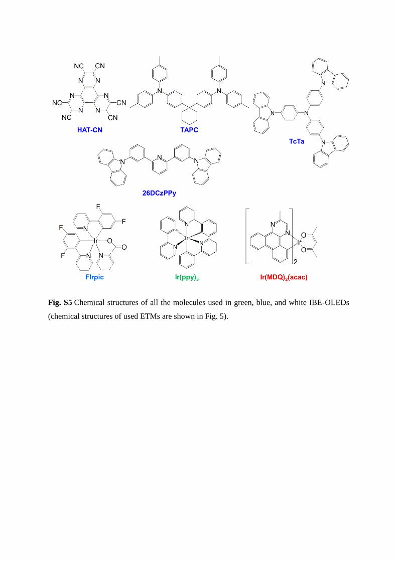
Fig. S5 Chemical structures of all the molecules used in green, blue, and white IBE-OLEDs
(chemical structures of used ETMs are shown in Fig. 5).
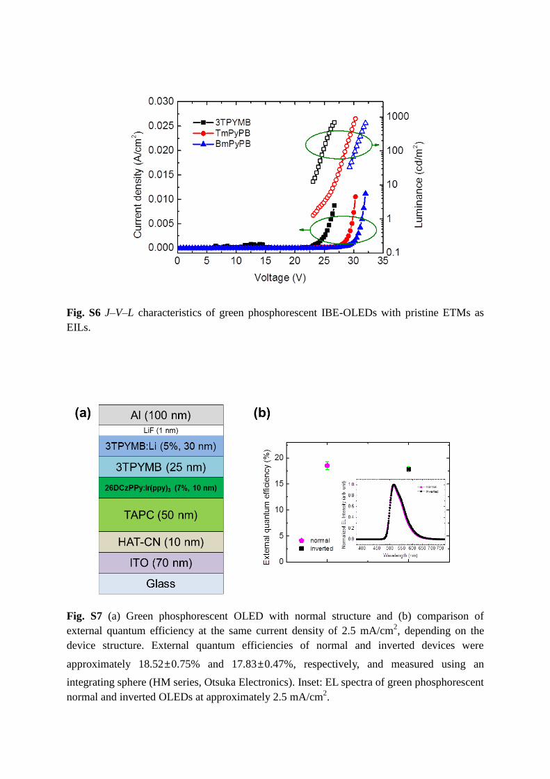
Fig. S6 J–V–L characteristics of green phosphorescent IBE-OLEDs with pristine ETMs as
EILs.
Fig. S7 (a) Green phosphorescent OLED with normal structure and (b) comparison of
external quantum efficiency at the same current density of 2.5 mA/cm2, depending on the
device structure. External quantum efficiencies of normal and inverted devices were
approximately 18.52±0.75% and 17.83±0.47%, respectively, and measured using an
integrating sphere (HM series, Otsuka Electronics). Inset: EL spectra of green phosphorescent
normal and inverted OLEDs at approximately 2.5 mA/cm2.

Fig. S8 (a) J–V characteristics of hole-only devices (HODs) with different HILs of HAT-CN
and MoO3 (Inset: schematic device structure) and (b) hole mobility of TAPC estimated from
HODs with HAT-CN using the SCLC model [4,5]. In this HOD, we used a low thickness of
TAPC (50 nm) for practical OLED application, and the hole mobility of TAPC obtained from
the HOD is lower than the previously reported value estimated from time-of-flight (TOF)
measurement. This may be due to the different device structure and low thickness of TAPC
compared with the TOF device (thicknesses of TAPC were between 6 and 11 μm) [6,7]. The
low hole mobility of TAPC in this structure improves electron-hole charge balance, resulting
in high efficiency because the electron mobilities of ETMs used in this work are of similar
orders of magnitude, as shown in Fig. 1(b).
Fig. S9 J–V–L characteristics of white phosphorescent IBE-OLEDs depending on TAPC
thickness.

Fig. S10 Optically simulated EL (a) intensity and (b) spectra of blue, green, and red OLEDs
depending on TAPC thickness.
REFERENCES
[1] D. Tanaka, T. Takeda, T. Chiba, S. Watanabe, J. Kido, Chem. Lett., 2007, 36, 262.
[2] S.-J. Su, T. Chiba, T. Takeda and J. Kido, Adv. Mater., 2008, 20, 2125.
[3] S.-J. Su, E. Gonmori, H. Sasabe and J. Kido, Adv. Mater., 2008, 20, 4189.
[4] P. N. Murgatroyd, J. Appl. Phys. D, 1970, 3, 151.
[5] J. C. Blakesley, F. A. Castro, W. Kylberg, G. F. A. Dibb, C. Arantes, R. Valaski, M.
Cremona, J. S. Kim and J.-S. Kim, Org. Electron., 2014, 15, 1263.
[6] P. M. Borsenberger, L. Pautmeier, R. Richert and H. Bässler, H., J. Chem. Phys., 1991, 94,
8276.
[7] T.-Y. Chu and O.-K. Song, Appl. Phys. Lett., 2007, 90, 203512.