SUPPLEMENTAL RESTRAINT SYSTEM (SRS) H RESTRAINTS SRS...
54
SRS-1 SUPPLEMENTAL RESTRAINT SYSTEM (SRS) H RESTRAINTS CONTENTS C D E F G I J K L M SECTION SRS A B SRS Revision: 2005 August 2005 350Z SUPPLEMENTAL RESTRAINT SYSTEM (SRS) PRECAUTIONS ......................................................... 3 Precautions for Supplemental Restraint System (SRS) “AIR BAG” and “SEAT BELT PRE-TEN- SIONER” ................................................................. 3 Precautions for SRS “AIR BAG” and “SEAT BELT PRE-TENSIONER” Service .................................... 3 Precautions for Battery Service ............................... 3 PREPARATION .......................................................... 4 Commercial Service Tools ....................................... 4 SUPPLEMENTAL RESTRAINT SYSTEM (SRS) ...... 5 SRS Configuration .................................................. 5 Front Seat Belt Pre-tensioner with Load Limiter ..... 6 Front Side Air Bag ................................................... 6 Side Curtain Air Bag/For Coupe .............................. 6 TROUBLE DIAGNOSIS ............................................. 7 Trouble Diagnosis Introduction ................................ 7 DIAGNOSIS FUNCTION ...................................... 7 HOW TO PERFORM TROUBLE DIAGNOSES FOR QUICK AND ACCURATE REPAIR .............. 7 WORK FLOW ....................................................... 8 Component Parts Location ...................................... 9 Schematic ............................................................. 10 Wiring Diagram — SRS —/For Coupe ................... 11 Wiring Diagram — SRS —/For Roadster .............. 15 CONSULT-II Function ........................................... 19 DIAGNOSIS MODE FOR CONSULT-II .............. 19 HOW TO CHANGE SELF-DIAGNOSIS MODE WITH CONSULT-II ............................................. 19 HOW TO ERASE SELF-DIAGNOSTIC RESULTS ........................................................... 20 Self-Diagnosis Function (Without CONSULT-II) .... 20 HOW TO CHANGE SELF-DIAGNOSTIC MODE WITHOUT CONSULT-II ..................................... 20 HOW TO ERASE SELF-DIAGNOSTIC RESULTS ........................................................... 20 SRS Operation Check ........................................... 21 DIAGNOSTIC PROCEDURE 1 .......................... 21 Trouble Diagnosis with CONSULT-II ..................... 23 DIAGNOSTIC PROCEDURE 2 .......................... 23 DIAGNOSTIC PROCEDURE 3 .......................... 27 DIAGNOSTIC PROCEDURE 4 (CONTINUED FROM DIAGNOSTIC PROCEDURE 2) ............. 29 DIAGNOSTIC PROCEDURE 5 .......................... 29 Trouble Diagnosis without CONSULT-II ................ 33 DIAGNOSTIC PROCEDURE 6 .......................... 33 WARNING LAMP FLASH CODE CHART .......... 34 Trouble Diagnosis: “AIR BAG” Warning Lamp Does Not Turn OFF ........................................................ 38 DIAGNOSTIC PROCEDURE 7 .......................... 38 Trouble Diagnosis: “AIR BAG” Warning Lamp Does Not Turn ON .......................................................... 39 DIAGNOSTIC PROCEDURE 8 .......................... 39 DRIVER AIR BAG MODULE ................................... 40 Removal and Installation ....................................... 40 REMOVAL .......................................................... 40 INSTALLATION .................................................. 41 SPIRAL CABLE ....................................................... 42 Removal and Installation ....................................... 42 REMOVAL .......................................................... 42 INSTALLATION .................................................. 43 FRONT PASSENGER AIR BAG MODULE ............. 44 Removal and Installation ....................................... 44 REMOVAL .......................................................... 44 INSTALLATION .................................................. 44 SIDE CURTAIN AIR BAG MODULE (FOR COUPE) ... 45 Removal and Installation ....................................... 45 REMOVAL .......................................................... 45 INSTALLATION .................................................. 46 CRASH ZONE SENSOR .......................................... 47 Removal and Installation ....................................... 47 REMOVAL .......................................................... 47 INSTALLATION .................................................. 47 SIDE AIR BAG (SATELLITE) SENSOR .................. 48 Removal and Installation ....................................... 48 REMOVAL .......................................................... 48 INSTALLATION .................................................. 48 FRONT SEAT BELT PRE-TENSIONER .................. 49 Removal and Installation ....................................... 49
Transcript of SUPPLEMENTAL RESTRAINT SYSTEM (SRS) H RESTRAINTS SRS...

SRS-1
SUPPLEMENTAL RESTRAINT SYSTEM (SRS)
H RESTRAINTS
CONTENTS
C
D
E
F
G
I
J
K
L
M
SECTION SRSA
B
SRS
Revision: 2005 August 2005 350Z
SUPPLEMENTAL RESTRAINT SYSTEM (SRS)
PRECAUTIONS .......................................................... 3Precautions for Supplemental Restraint System (SRS) “AIR BAG” and “SEAT BELT PRE-TEN-SIONER” .................................................................. 3Precautions for SRS “AIR BAG” and “SEAT BELT PRE-TENSIONER” Service ..................................... 3Precautions for Battery Service ................................ 3
PREPARATION ........................................................... 4Commercial Service Tools ........................................ 4
SUPPLEMENTAL RESTRAINT SYSTEM (SRS) ....... 5SRS Configuration ................................................... 5Front Seat Belt Pre-tensioner with Load Limiter ...... 6Front Side Air Bag .................................................... 6Side Curtain Air Bag/For Coupe ............................... 6
TROUBLE DIAGNOSIS .............................................. 7Trouble Diagnosis Introduction ................................. 7
DIAGNOSIS FUNCTION ....................................... 7HOW TO PERFORM TROUBLE DIAGNOSES FOR QUICK AND ACCURATE REPAIR ............... 7WORK FLOW ........................................................ 8
Component Parts Location ....................................... 9Schematic .............................................................. 10Wiring Diagram — SRS —/For Coupe ....................11Wiring Diagram — SRS —/For Roadster ............... 15CONSULT-II Function ............................................ 19
DIAGNOSIS MODE FOR CONSULT-II ............... 19HOW TO CHANGE SELF-DIAGNOSIS MODE WITH CONSULT-II .............................................. 19HOW TO ERASE SELF-DIAGNOSTIC RESULTS ............................................................ 20
Self-Diagnosis Function (Without CONSULT-II) ..... 20HOW TO CHANGE SELF-DIAGNOSTIC MODE WITHOUT CONSULT-II ...................................... 20HOW TO ERASE SELF-DIAGNOSTIC RESULTS ............................................................ 20
SRS Operation Check ............................................ 21DIAGNOSTIC PROCEDURE 1 ........................... 21
Trouble Diagnosis with CONSULT-II ...................... 23DIAGNOSTIC PROCEDURE 2 ........................... 23
DIAGNOSTIC PROCEDURE 3 ........................... 27DIAGNOSTIC PROCEDURE 4 (CONTINUED FROM DIAGNOSTIC PROCEDURE 2) .............. 29DIAGNOSTIC PROCEDURE 5 ........................... 29
Trouble Diagnosis without CONSULT-II ................. 33DIAGNOSTIC PROCEDURE 6 ........................... 33WARNING LAMP FLASH CODE CHART ........... 34
Trouble Diagnosis: “AIR BAG” Warning Lamp Does Not Turn OFF ......................................................... 38
DIAGNOSTIC PROCEDURE 7 ........................... 38Trouble Diagnosis: “AIR BAG” Warning Lamp Does Not Turn ON ........................................................... 39
DIAGNOSTIC PROCEDURE 8 ........................... 39DRIVER AIR BAG MODULE .................................... 40
Removal and Installation ........................................ 40REMOVAL ........................................................... 40INSTALLATION ................................................... 41
SPIRAL CABLE ........................................................ 42Removal and Installation ........................................ 42
REMOVAL ........................................................... 42INSTALLATION ................................................... 43
FRONT PASSENGER AIR BAG MODULE .............. 44Removal and Installation ........................................ 44
REMOVAL ........................................................... 44INSTALLATION ................................................... 44
SIDE CURTAIN AIR BAG MODULE (FOR COUPE) ... 45Removal and Installation ........................................ 45
REMOVAL ........................................................... 45INSTALLATION ................................................... 46
CRASH ZONE SENSOR ........................................... 47Removal and Installation ........................................ 47
REMOVAL ........................................................... 47INSTALLATION ................................................... 47
SIDE AIR BAG (SATELLITE) SENSOR ................... 48Removal and Installation ........................................ 48
REMOVAL ........................................................... 48INSTALLATION ................................................... 48
FRONT SEAT BELT PRE-TENSIONER ................... 49Removal and Installation ........................................ 49

SRS-2Revision: 2005 August 2005 350Z
DIAGNOSIS SENSOR UNIT ..................................... 50Removal and Installation ........................................ 50
REMOVAL ........................................................... 50INSTALLATION .................................................... 50ECU DISCRIMINATED NO. ................................. 50
COLLISION DIAGNOSIS .......................................... 51For Frontal Collision ................................................ 51
SRS INSPECTION (FOR FRONTAL COLLI-
SION) ...................................................................51For Side Collision ....................................................53
WHEN THE SIDE AIR BAG IS ACTIVATED IN THE SIDE COLLISION: .......................................53WHEN SRS IS NOT ACTIVATED IN THE SIDE COLLISION: .........................................................53SRS INSPECTION (FOR SIDE COLLISION) ......53

PRECAUTIONS
SRS-3
C
D
E
F
G
I
J
K
L
M
A
B
SRS
Revision: 2005 August 2005 350Z
PRECAUTIONS PFP:00001
Precautions for Supplemental Restraint System (SRS) “AIR BAG” and “SEAT BELT PRE-TENSIONER” AHS0001K
The Supplemental Restraint System such as “AIR BAG” and “SEAT BELT PRE-TENSIONER”, used alongwith a front seat belt, helps to reduce the risk or severity of injury to the driver and front passenger for certaintypes of collision. This system includes seat belt switch inputs and dual stage front air bag modules. The SRSsystem uses the seat belt switches to determine the front air bag deployment, and may only deploy one frontair bag, depending on the severity of a collision and whether the front occupants are belted or unbelted.Information necessary to service the system safely is included in the SRS and SB section of this Service Man-ual.WARNING:● To avoid rendering the SRS inoperative, which could increase the risk of personal injury or death
in the event of a collision which would result in air bag inflation, all maintenance must be per-formed by an authorized NISSAN/INFINITI dealer.
● Improper maintenance, including incorrect removal and installation of the SRS, can lead to per-sonal injury caused by unintentional activation of the system. For removal of Spiral Cable and AirBag Module, see the SRS section.
● Do not use electrical test equipment on any circuit related to the SRS unless instructed to in thisService Manual. SRS wiring harnesses can be identified by yellow and/or orange harnesses orharness connectors.
Precautions for SRS “AIR BAG” and “SEAT BELT PRE-TENSIONER” ServiceAHS000JX
● Do not use electrical test equipment to check SRS circuits unless instructed in this Service Manual.● Before servicing the SRS, turn ignition switch OFF, and disconnect both battery cables. Then wait at least
3 minutes.For approximately 3 minutes after the cables are removed, it is still possible for the air bag and seat beltpre-tensioner to deploy. Therefore, do not work on any SRS connectors or wires until at least 3 minuteshave passed.
● Diagnosis sensor unit must always be installed with their arrow marks “⇐ ” pointing towards the front of thevehicle for proper operation. Also check diagnosis sensor unit for cracks, deformations or rust beforeinstallation and replace if required.
● The spiral cable must be set to the neutral position since its rotations are limited. Do not attempt to turnsteering wheel or column, if steering gear was disconnected from the column shaft.
● Handle air bag module carefully. Always put a driver air bag module with the pad side facing upward.● Conduct self-diagnosis to check entire SRS for proper function after replacing any components.● After an air bag deploymented, the front instrument panel assembly should be replaced if damaged.● Always replace instrument panel pad following front passenger air bag deployment.
Precautions for Battery Service AHS000NY
Before disconnecting the battery, lower both the driver and passenger windows. This will prevent any interfer-ence between the window edge and the vehicle when the door is opened/closed. During normal operation, thewindow slightly raises and lowers automatically to prevent any window to vehicle interference. The automaticwindow function will not work with the battery disconnected.

SRS-4
PREPARATION
Revision: 2005 August 2005 350Z
PREPARATION PFP:00002
Commercial Service Tools AHS0001O
Tool name Description
Tamper resistant TORX bit Size: T30
S-NT757

SUPPLEMENTAL RESTRAINT SYSTEM (SRS)
SRS-5
C
D
E
F
G
I
J
K
L
M
A
B
SRS
Revision: 2005 August 2005 350Z
SUPPLEMENTAL RESTRAINT SYSTEM (SRS) PFP:28556
SRS Configuration AHS0001P
The air bag deploys if the diagnosis sensor unit activates while the ignition switch is in the ON or START posi-tion.The collision modes for which supplemental restraint systems are activated are different among the SRS sys-tems. For example, the driver air bag module and front passenger air bag module are activated in a frontal col-lision but not in a side collision.SRS configurations which are activated for some collision modes are as follows;
*: For Coupe
PHIA0459E
SRS configuration Frontal collision Left side collision Right side collision
Driver air bag module × — —
Front passenger air bag module × — —
Front LH seat belt pre-tensioner × — —
Front RH seat belt pre-tensioner × — —
Front LH side air bag module — × —
Front RH side air bag module — — ×
LH side curtain air bag module* — × —
RH side curtain air bag module* — — ×

SRS-6
SUPPLEMENTAL RESTRAINT SYSTEM (SRS)
Revision: 2005 August 2005 350Z
Front Seat Belt Pre-tensioner with Load Limiter AHS0001Q
The seat belt pre-tensioner system with load limiter is installed forboth the driver's seat and the front passenger seat. It operates simul-taneously with the SRS air bag system in the event of a frontal colli-sion with an impact exceeding a specified level.When the frontal collision with an impact exceeding a specified leveloccurs, seat belt slack resulting from clothing or other factors isimmediately taken up by the pre-tensioner. Vehicle passengers aresecurely restrained.When passengers in a vehicle are thrown forward in a collision andthe restraining force of the seat belt exceeds a specified level, theload limiter permits the specified extension of the seat belt by thetwisting of the ELR shaft, and a relaxation of the chest-area seat beltweb tension while maintaining force.
Front Side Air Bag AHS0001R
Front side air bag is built-in type.The front seatbacks with built-in type side air bag have the labels asshown.
Side Curtain Air Bag/For Coupe AHS0001S
The side curtain air bags have the labels as shown.
SRS444
PHIA0158E
PHIA0159E

TROUBLE DIAGNOSIS
SRS-7
C
D
E
F
G
I
J
K
L
M
A
B
SRS
Revision: 2005 August 2005 350Z
TROUBLE DIAGNOSIS PFP:00004
Trouble Diagnosis Introduction AHS0001T
CAUTION:● Do not use electrical test equipment on any circuit related to the SRS unless instructed in this Ser-
vice Manual. SRS wiring harnesses can be identified by yellow and/or orange harnesses or har-ness connectors.
● Do not repair, splice or modify the SRS wiring harness. If the harness is damaged, replace it with anew one.
● Keep ground portion clean.
DIAGNOSIS FUNCTIONThe SRS self-diagnostic results can be read by using “AIR BAG” warning lamp and/or CONSULT-II.The User mode is exclusively prepared for the customer (driver). This mode warns the driver of a system mal-function through the operation of the “AIR BAG” warning lamp.The Diagnosis mode allows the technician to locate and inspect the malfunctioning part.The mode applications for the “AIR BAG” warning lamp and CONSULT-II are as follows:
HOW TO PERFORM TROUBLE DIAGNOSES FOR QUICK AND ACCURATE REPAIRA good understanding of the malfunction conditions can make troubleshooting faster and more accurate.In general, each customer feels differently about a malfunction. It is important to fully understand the symp-toms or conditions for a customer complaint.
Information from CustomerWHAT..... Vehicle modelWHEN..... Date, FrequenciesWHERE..... Road conditionsHOW..... Operating conditions, Symptoms
Preliminary CheckMake sure that the following parts are in good order.● Battery (Refer to SC-4, "How to Handle Battery" .)● Fuse (Refer to SRS-11, "Wiring Diagram — SRS —/For Coupe" or SRS-15, "Wiring Diagram — SRS —/
For Roadster" .)● System component-to-harness connections
User mode Diagnosis mode Display type
“AIR BAG” warning lamp X X ON-OFF operation
CONSULT-II — X Monitoring

SRS-8
TROUBLE DIAGNOSIS
Revision: 2005 August 2005 350Z
WORK FLOW
*1: SRS-7, "Preliminary Check". *2: SRS-21, "SRS Operation Check". *3: SRS-23, "DIAGNOSTIC PROCE-DURE 2".
*4: SRS-33, "DIAGNOSTIC PROCE-DURE 6".
*5 SRS-27, "DIAGNOSTIC PROCE-DURE 3".
*6 SRS-33, "DIAGNOSTIC PROCE-DURE 6".
PHIA0217E

TROUBLE DIAGNOSIS
SRS-9
C
D
E
F
G
I
J
K
L
M
A
B
SRS
Revision: 2005 August 2005 350Z
Component Parts Location AHS0001U
*: For Coupe
PHIA0160E
1. Driver air bag module 2. Front passenger air bag module 3. Spiral cable
4. Front side air bag module 5. Diagnosis sensor unit 6. Side air bag (Satellite) sensor LH
7. Side air bag (Satellite) sensor RH 8. Seat belt pre-tensioner RH 9. Seat belt buckle switches
10. Seat belt pre-tensioner LH 11. Side curtain air bag module* 12. Crash zone sensor

SRS-10
TROUBLE DIAGNOSIS
Revision: 2005 August 2005 350Z
Schematic AHS0001V
THWT0079E

TROUBLE DIAGNOSIS
SRS-11
C
D
E
F
G
I
J
K
L
M
A
B
SRS
Revision: 2005 August 2005 350Z
Wiring Diagram — SRS —/For Coupe AHS0001W
THWT0095E

SRS-12
TROUBLE DIAGNOSIS
Revision: 2005 August 2005 350Z
THWT0081E

TROUBLE DIAGNOSIS
SRS-13
C
D
E
F
G
I
J
K
L
M
A
B
SRS
Revision: 2005 August 2005 350Z
THWT0082E

SRS-14
TROUBLE DIAGNOSIS
Revision: 2005 August 2005 350Z
THWT0083E

TROUBLE DIAGNOSIS
SRS-15
C
D
E
F
G
I
J
K
L
M
A
B
SRS
Revision: 2005 August 2005 350Z
Wiring Diagram — SRS —/For Roadster AHS000JO
THWT0096E

SRS-16
TROUBLE DIAGNOSIS
Revision: 2005 August 2005 350Z
THWT0085E

TROUBLE DIAGNOSIS
SRS-17
C
D
E
F
G
I
J
K
L
M
A
B
SRS
Revision: 2005 August 2005 350Z
THWT0086E

SRS-18
TROUBLE DIAGNOSIS
Revision: 2005 August 2005 350Z
THWT0087E

TROUBLE DIAGNOSIS
SRS-19
C
D
E
F
G
I
J
K
L
M
A
B
SRS
Revision: 2005 August 2005 350Z
CONSULT-II Function AHS0001X
DIAGNOSIS MODE FOR CONSULT-II● “SELF-DIAG [CURRENT]”
A current self-diagnostic results (also indicated by the number of warning lamp flashes in the Diagnosismode) is displayed on the CONSULT-II screen in real time. This refers to a malfunctioning part requiringrepairs.
● “SELF-DIAG [PAST]”Self-diagnostic results previously stored in the memory are displayed on the CONSULT-II screen. Thestored results are not erased until memory erasing is performed.
● “TROUBLE DIAG RECORD”With TROUBLE DIAG RECORD, diagnostic results previously erased by a reset operation can be dis-played on the CONSULT-II screen.
● “ECU DISCRIMINATED NO.”The diagnosis sensor unit for each vehicle model is assignedwith its own, individual classification number. This number willbe displayed on the CONSULT-II screen, as shown. Whenreplacing the diagnosis sensor unit, refer to the part number forthe compatibility. After installation, replacement with a correctunit can be checked by confirming this classification number onthe CONSULT-II screen.After repair, make sure the discriminated number of diagnosissensor unit installed to vehicle are same. Refer to SRS-50,"ECU DISCRIMINATED NO." .
HOW TO CHANGE SELF-DIAGNOSIS MODE WITH CONSULT-IIFrom User Mode to Diagnosis ModeAfter selecting “AIR BAG” on the “SELECT SYSTEM” screen, User mode automatically changes to Diagnosismode.
From Diagnosis Mode to User ModeTo return to User mode from Diagnosis mode, touch “BACK” key of CONSULT-II until “SELECT SYSTEM”appears, then diagnosis mode automatically changes to User mode.
PHIA0218E
SRS803
SRS804

SRS-20
TROUBLE DIAGNOSIS
Revision: 2005 August 2005 350Z
HOW TO ERASE SELF-DIAGNOSTIC RESULTS● “SELF-DIAG [CURRENT]”
A current self-diagnostic result is displayed on the CONSULT-II screen in real time.After the malfunction is repaired completely, no malfunction is detected on “SELF-DIAG [CURRENT]”.
● “SELF-DIAG [PAST]”Return to the “SELF-DIAG [CURRENT]” CONSULT-II screen by touching “BACK” key of CONSULT-II andselect “SELF-DIAG [CURRENT]” in SELECT DIAG MODE. Touch “ERASE” in “SELF-DIAG [CURRENT]”mode.NOTE:If the memory of the malfunction in “SELF-DIAG [PAST]” is not erased, the User mode shows the systemmalfunction by the operation of the warning lamp even if the malfunction is repaired completely.
● “TROUBLE DIAG RECORD”The memory of “TROUBLE DIAG RECORD” cannot be erased.
Self-Diagnosis Function (Without CONSULT-II) AHS0001Y
● The reading of these results is accomplished “User mode” and “Diagnosis mode”.● After a malfunction is repaired, turn ignition switch ON. Diagnosis mode returns to the User mode. At that
time, the self-diagnostic result is cleared.
HOW TO CHANGE SELF-DIAGNOSTIC MODE WITHOUT CONSULT-II
HOW TO ERASE SELF-DIAGNOSTIC RESULTSAfter a malfunction is repaired, turn the ignition switch OFF for at least one second, then back ON. Diagnosismode returns to the User mode. At that time, the self-diagnostic results are cleared.
SRS701
PHIA0709E

TROUBLE DIAGNOSIS
SRS-21
C
D
E
F
G
I
J
K
L
M
A
B
SRS
Revision: 2005 August 2005 350Z
SRS Operation Check AHS0001Z
DIAGNOSTIC PROCEDURE 1Checking Air Bag Operation by Using “AIR BAG” Warning Lamp — User Mode1. Turn ignition switch from OFF to ON, and make sure that the air bag warning lamp blinks.2. Compare the SRS air bag warning lamp blinking pattern with the
examples.
BF-1845D

SRS-22
TROUBLE DIAGNOSIS
Revision: 2005 August 2005 350Z
Warning lamp examples
“AIR BAG” warning lamp operation-User mode- SRS condition Reference item
● No malfunction is detected.
● No further action is necessary.—
● The system is malfunctioning and needs to be repaired as indicated.
Go to SRS-23, "DIAGNOSTIC PROCEDURE 2" or SRS-33, "DIAGNOSTIC PROCEDURE 6" .
● Air bag is deployed.
● Seat belt pre-tensioner is deployed.
Go to SRS-51, "COLLISION DIAG-NOSIS" .
● Diagnosis sensor unit is malfunction-ing.
● Air bag power supply circuit is mal-functioning.
● SRS air bag warning lamp circuit is malfunctioning.
Go to SRS-38, "Trouble Diagnosis: “AIR BAG” Warning Lamp Does Not Turn OFF" .
● Diagnosis sensor unit is malfunction-ing.
● Air bag warning lamp circuit is mal-functioning.
Go to SRS-39, "Trouble Diagnosis: “AIR BAG” Warning Lamp Does Not Turn ON" .
SHIA0011E
SHIA0012E
SHIA0013E
SHIA0014E

TROUBLE DIAGNOSIS
SRS-23
C
D
E
F
G
I
J
K
L
M
A
B
SRS
Revision: 2005 August 2005 350Z
Trouble Diagnosis with CONSULT-II AHS0009A
DIAGNOSTIC PROCEDURE 2CAUTION:If CONSULT-II is used with no connection of CONSULT-II CONVERTER, malfunctions might bedetected in self-diagnosis depending on control unit which carry out CAN communication.1. Turn ignition switch OFF.2. Connect CONSULT-II and CONSULT-II CONVERTER to the
data link connector.
3. Turn ignition switch ON.4. Touch “START (NISSAN BASED VHCL)”.
5. Touch “AIR BAG”.If “AIR BAG” is not indicated, go to GI-39, "CONSULT-II DataLink Connector (DLC) Circuit" .
6. Touch “SELF-DIAG [CURRENT]”.
PBIB1069E
BCIA0029E
BCIA0030E
SRS697

SRS-24
TROUBLE DIAGNOSIS
Revision: 2005 August 2005 350Z
7. Diagnostic code is displayed on “SELF-DIAG [CURRENT]”.
If no malfunction is detected on “SELF-DIAG [CURRENT]” eventhough malfunction is detected in “SRS Operation Check”, check thebattery voltage. If the battery voltage is less than 9 V, charge orreplace the battery. SRS-27, "DIAGNOSTIC PROCEDURE 3" . If thebattery voltage is OK, go to SRS-29, "DIAGNOSTIC PROCEDURE4 (CONTINUED FROM DIAGNOSTIC PROCEDURE 2)" diagnosethe following cases:● Self-diagnostic result “SELF-DIAG [PAST]” (previously stored in
the memory) might not be erased after repair.● The SRS system malfunctions intermittently.
CONSULT-II Diagnostic Code Chart (“SELF-DIAG [CURRENT]”)
SHIA0203E
SRS701
Diagnostic item ExplanationRepair order
“Recheck SRS at each replacement”
NO DTC IS DETECTED. When malfunction is indicated by the “AIR BAG” warning lamp in User mode.
● Low battery voltage (Less than 9V) ● Go to SRS-27, "DIAGNOSTIC PRO-CEDURE 3" after charging the bat-tery.
● Self-diagnostic results “SELF-DIAG [PAST]” (previously stored in the memory) might not be erased after repair.
● Intermittent malfunction has been detected in the past.
● Go to SRS-29, "DIAGNOSTIC PRO-CEDURE 4 (CONTINUED FROM DIAGNOSTIC PROCEDURE 2)" .
● Go to SRS-29, "DIAGNOSTIC PRO-CEDURE 5" .
● No malfunction is detected. —
DRIVER AIRBAG MOD-ULE[OPEN]
● Driver air bag module circuit is open (including the spiral cable).
1. Visually check the wiring harness connection.
2. Replace the harness if it has visible damage.
3. Replace driver air bag module.
4. Replace the spiral cable.
5. Replace the diagnosis sensor unit.
6. Replace the related harness.
DRIVER AIRBAG MOD-ULE[VB-SHORT]
● Driver air bag module circuit is shorted to a power supply cir-cuit (including the spiral cable).
DRIVER AIRBAG MOD-ULE[GND-SHORT]
● Driver air bag module circuit is shorted to ground (including the spiral cable).
DRIVER AIRBAG MOD-ULE[SHORT]
● Driver air bag module circuit is shorted between lines.
ASSIST A/B MODULE[VB-SHORT]
● Front passenger air bag module circuit is shorted to a power supply circuit.
1. Visually check the wiring harness connection.
2. Replace the harness if it has visible damage.
3. Replace front passenger air bag module.
4. Replace the diagnosis sensor unit.
5. Replace the related harness.
ASSIST A/B MODULE[OPEN]
● Front passenger air bag module circuit is open.
ASSIST A/B MODULE[GND-SHORT]
● Front passenger air bag module circuit is shorted to ground.
ASSIST A/B MODULE[SHORT]
● Front passenger air bag module circuit is shorted between lines.

TROUBLE DIAGNOSIS
SRS-25
C
D
E
F
G
I
J
K
L
M
A
B
SRS
Revision: 2005 August 2005 350Z
CRASH ZONE SEN[UNIT FAIL]CRASH ZONE SEN[COMM FAIL]CRASH ZONE SEN[UNMATCH]
● Crash zone sensor 1. Visually check the wiring harness connection.
2. Replace the harness if it has visible damage.
3. Replace the crash zone sensor.
4. Replace the diagnosis sensor unit.
5. Replace the related harness.
SIDE MODULE LH[OPEN]
● Front LH side air bag module circuit is open. 1. Visually check the wiring harness connection.
2. Replace the harness if it has visible damage.
3. Replace front LH setback assembly (front LH side air bag module).
4. Replace the diagnosis sensor unit.
5. Replace the related harness.
SIDE MODULE LH[VB-SHORT]
● Front LH side air bag module circuit is shorted to a power sup-ply circuit.
SIDE MODULE LH[GND-SHORT]
● Front LH side air bag module circuit is shorted to ground.
SIDE MODULE LH[SHORT]
● Front LH side air bag module circuit is shorted between lines.
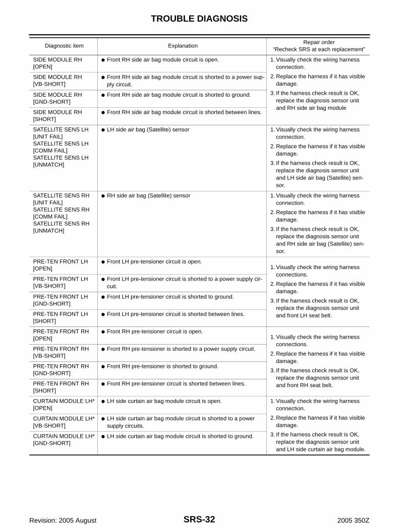
SIDE MODULE RH[OPEN]
● Front RH side air bag module circuit is open. 1. Visually check the wiring harness connection.
2. Replace the harness if it has visible damage.
3. Replace front RH setback assembly (front RH side air bag module).
4. Replace the diagnosis sensor unit.
5. Replace the related harness.
SIDE MODULE RH[VB-SHORT]
● Front RH side air bag module circuit is shorted to some power supply circuit.
SIDE MODULE RH[GND-SHORT]
● Front RH side air bag module circuit is shorted to ground.
SIDE MODULE RH[SHORT]
● Front RH side air bag module circuit is shorted between lines.
SATELLITE SENS LH[UNIT FAIL]SATELLITE SENS LH[COMM FAIL]SATELLITE SENS LH[UNMATCH]
● LH side air bag (Satellite) sensor 1. Visually check the wiring harness connection.
2. Replace the harness if it has visible damage.
3. Replace the LH side air bag (Satel-lite) sensor.
4. Replace the diagnosis sensor unit.
5. Replace the related harness.
SATELLITE SENS RH[UNIT FAIL]SATELLITE SENS RH[COMM FAIL]SATELLITE SENS RH[UNMATCH]
● RH side air bag (Satellite) sensor 1. Visually check the wiring harness connection.
2. Replace the harness if it has visible damage.
3. Replace the RH side air bag (Satel-lite) sensor.
4. Replace the diagnosis sensor unit.
5. Replace the related harness.
PRE-TEN FRONT LH[OPEN]
● Front LH pre-tensioner circuit is open. 1. Visually check the wiring harness
connections.
2. Replace the harness if it has visible damage.
3. Replace front LH seat belt.
4. Replace the diagnosis sensor unit.
5. Replace the related harness.
PRE-TEN FRONT LH[VB-SHORT]
● Front LH pre-tensioner circuit is shorted to a power supply cir-cuit.
PRE-TEN FRONT LH[GND-SHORT]
● Front LH pre-tensioner circuit is shorted to ground.
PRE-TEN FRONT LH[SHORT]
● Front LH pre-tensioner circuit is shorted between lines.
Diagnostic item ExplanationRepair order
“Recheck SRS at each replacement”

SRS-26
TROUBLE DIAGNOSIS
Revision: 2005 August 2005 350Z
*: For coupe
NOTE:● Follow the procedures in numerical order when repairing malfunctioning parts. Confirm whether malfunc-
tion is eliminated using air bag warning lamp or CONSULT-II each time repair is finished. If malfunction isstill observed, proceed to the next step. When malfunction is eliminated, further repair work is notrequired.
PRE-TEN FRONT RH[OPEN]
● Front RH pre-tensioner circuit is shorted to a power supply cir-cuit.
1. Visually check the wiring harness connections.
2. Replace the harness if it has visible damage.
3. Replace front RH seat belt.
4. Replace the diagnosis sensor unit.
5. Replace the related harness.
PRE-TEN FRONT RH[VB-SHORT]
● Front RH pre-tensioner is shorted to a power supply circuit.
PRE-TEN FRONT RH[GND-SHORT]
● Front RH pre-tensioner circuit is shorted to ground.
PRE-TEN FRONT RH[SHORT]
● Front RH pre-tensioner circuit is shorted between lines.
CURTAIN MODULE LH*[OPEN]
● LH side curtain air bag module circuit is open. 1. Visually check the wiring harness connection.
2. Replace the harness if it has visible damage.
3. Replace LH side curtain air bag module.
4. Replace the diagnosis sensor unit.
5. Replace the related harness.
CURTAIN MODULE LH*[VB-SHORT]
● LH side curtain air bag module circuit is shorted to some power supply circuits.
CURTAIN MODULE LH*[GND-SHORT]
● LH side curtain air bag module circuit is shorted to ground.
CURTAIN MODULE LH*[SHORT]
● LH side curtain air bag module circuit is shorted between lines.
CURTAIN MODULE RH*[OPEN]
● RH side curtain air bag module circuit is open. 1. Visually check the wiring harness connection.
2. Replace the harness if it has visible damage.
3. Replace RH side curtain air bag module.
4. Replace the diagnosis sensor unit.
5. Replace the related harness.
CURTAIN MODULE RH*[VB-SHORT]
● RH side curtain air bag module circuit is shorted to a power supply circuit.
CURTAIN MODULE RH*[GND-SHORT]
● RH side curtain air bag module circuit is shorted to ground.
CURTAIN MODULE RH*[SHORT]
● RH side curtain air bag module circuit is shorted between lines.
CONTROL UNIT ● Diagnosis sensor unit is malfunctioning. 1. Visually check the wiring harness connection.
2. Replace the diagnosis sensor unit.
FRONTAL COLLISION DETECTION
● Seat belt pre-tensioner and front air bag are deployed. ● Go to SRS-51, "For Frontal Colli-sion" .
SIDE COLLISION DETECTION*
● Curtain air bag is deployed. ● Go to SRS-53, "For Side Collision" .
Diagnostic item ExplanationRepair order
“Recheck SRS at each replacement”
TROUBLE DIAGNOSIS
SRS-27
C
D
E
F
G
I
J
K
L
M
A
B
SRS
Revision: 2005 August 2005 350Z
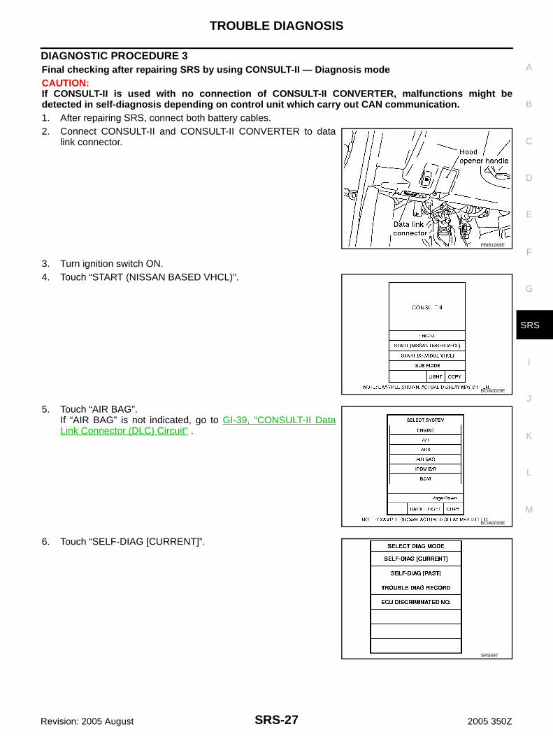
DIAGNOSTIC PROCEDURE 3Final checking after repairing SRS by using CONSULT-II — Diagnosis modeCAUTION:If CONSULT-II is used with no connection of CONSULT-II CONVERTER, malfunctions might bedetected in self-diagnosis depending on control unit which carry out CAN communication.1. After repairing SRS, connect both battery cables.2. Connect CONSULT-II and CONSULT-II CONVERTER to data
link connector.
3. Turn ignition switch ON.4. Touch “START (NISSAN BASED VHCL)”.
5. Touch “AIR BAG”.If “AIR BAG” is not indicated, go to GI-39, "CONSULT-II DataLink Connector (DLC) Circuit" .
6. Touch “SELF-DIAG [CURRENT]”.
PBIB1069E
BCIA0029E
BCIA0030E
SRS697

SRS-28
TROUBLE DIAGNOSIS
Revision: 2005 August 2005 350Z
7. If no malfunction is detected on “SELF-DIAG [CURRENT]”,repair of SRS is completed. Go to step 8.If any malfunction is detected on “SELF-DIAG [CURRENT]”, themalfunctioning part is not repaired completely or another mal-functioning part is detected. Go to SRS-23, "DIAGNOSTICPROCEDURE 2" , and repair malfunctioning part completely.
8. Touch “ERASE”.NOTE:● Touch “ERASE” to clear the memory of the malfunction
(“SELF-DIAG [PAST]”).● If the memory of the malfunction in “SELF-DIAG [PAST]” is
not erased, the User mode shows the system malfunction bythe operation of the warning lamp even if the malfunction isrepaired completely.
9. Touch “BACK” key of CONSULT-II to “SELECT DIAG MODE”screen. Touch “SELF-DIAG [PAST]”.
10. Make sure that no malfunction is detected on “SELF-DIAG[PAST]”.
11. Touch “BACK” key of CONSULT-II until “SELECT SYSTEM”appears in order to return to User mode from Diagnosis mode.
12. Turn ignition switch OFF then turn off and disconnect CON-SULT-II. Go to SRS-21, "Checking Air Bag Operation by Using“AIR BAG” Warning Lamp — User Mode" .
SRS701
SRS773
SRS697
SRS702

TROUBLE DIAGNOSIS
SRS-29
C
D
E
F
G
I
J
K
L
M
A
B
SRS
Revision: 2005 August 2005 350Z
DIAGNOSTIC PROCEDURE 4 (CONTINUED FROM DIAGNOSTIC PROCEDURE 2)Inspecting SRS malfunctioning record
1. CONSIDER POSSIBILITY OF NOT ERASING SELF-DIAGNOSTIC RESULT AFTER REPAIRING
Is it the first time for maintenance of SRS?YES or NOYES >> Go to SRS-23, "DIAGNOSTIC PROCEDURE 2" .NO >> Self-diagnostic result “SELF-DIAG [PAST]” (previously stored in the memory) might not be erased
after repair. Go to SRS-27, "DIAGNOSTIC PROCEDURE 3" .
DIAGNOSTIC PROCEDURE 5Inspecting SRS intermittent malfunction by using CONSULT-II — Diagnosis modeCAUTION:If CONSULT-II is used with no connection of CONSULT-II CONVERTER, malfunction might be detectedin self-diagnosis depending on control unit which carry out CAN communication.1. Turn ignition switch OFF.2. Connect CONSULT-II and CONSULT-II CONVERTER to data
link connector.
3. Turn ignition switch ON.4. Touch “START (NISSAN BASED VHCL)”.
5. Touch “AIR BAG”.If “AIR BAG” is not indicated, go to GI-39, "CONSULT-II DataLink Connector (DLC) Circuit" .
PBIB1069E
BCIA0029E
BCIA0030E

SRS-30
TROUBLE DIAGNOSIS
Revision: 2005 August 2005 350Z
6. Touch “SELF-DIAG [PAST]”.
7. If diagnostic codes are displayed on “SELF-DIAG [PAST]”, go tostep 10.
If no malfunction is detected on “SELF-DIAG [PAST]”, touch“BACK” and go back to “SELECT DIAG MODE”.
8. Touch “TROUBLE DIAG RECORD”.NOTE:With “TROUBLE DIAG RECORD”, diagnosis results previouslyerased by a reset operation can be displayed.
9. Diagnostic code is displayed on “TROUBLE DIAG RECORD”.10. Touch “PRINT”.11. Compare diagnostic codes to SRS-31, "CONSULT-II Diagnostic
Code Chart (“SELF-DIAG [PAST]” or “TROUBLE DIAGRECORD”)" .
12. Touch “BACK” key of CONSULT-II until “SELECT SYSTEM”appears.
13. Turn ignition switch OFF, then turn off and disconnect CON-SULT-II, and both battery cables.
SRS697
SRS700
SRS702
SRS697
SHIA0182E

TROUBLE DIAGNOSIS
SRS-31
C
D
E
F
G
I
J
K
L
M
A
B
SRS
Revision: 2005 August 2005 350Z
14. Repair the system as outlined by the “Repair order” in “Intermittent Malfunction Diagnostic Code Chart”,that corresponds to the self-diagnostic result. For replacement procedure of component parts, refer to theRemoval and Installation procedure for the appropriate component.
15. Go to SRS-27, "DIAGNOSTIC PROCEDURE 3" , for final checking.
CONSULT-II Diagnostic Code Chart (“SELF-DIAG [PAST]” or “TROUBLE DIAG RECORD”)
Diagnostic item ExplanationRepair order
“Recheck SRS at each replacement”
NO DTC IS DETECTED. When malfunction is indicated by the “AIR BAG” warning lamp in User mode.
● Low battery voltage (Less than 9V) ● Go to SRS-27, "DIAGNOSTIC PRO-CEDURE 3" .
● No malfunction is detected. ● Go to SRS-27, "DIAGNOSTIC PRO-CEDURE 3" .
DRIVER AIRBAG MOD-ULE[OPEN]
● Driver air bag module circuit is open (including the spiral cable).
1. Visually check the wiring harness connection.
2. Replace the harness if it has visible damage.
3. If the harness check result is OK, replace driver air bag module, diag-nosis sensor unit and spiral cable.
DRIVER AIRBAG MOD-ULE[VB-SHORT]
● Driver air bag module circuit is shorted to a power supply cir-cuit (including the spiral cable).
DRIVER AIRBAG MOD-ULE[GND-SHORT]
● Driver air bag module circuit is shorted to ground (including the spiral cable).
DRIVER AIRBAG MOD-ULE[SHORT]
● Driver air bag module circuit is shorted between lines.
ASSIST A/B MODULE[OPEN]
● Front passenger air bag module circuit is open. 1. Visually check the wiring harness connection.
2. Replace the harness if it has visible damage.
3. If the harness check result is OK, replace the diagnosis sensor unit and front passenger air bag module.
ASSIST A/B MODULE[VB-SHORT]
● Front passenger air bag module circuit is shorted to a power supply circuit.
ASSIST A/B MODULE[GND-SHORT]
● Front passenger air bag module circuit is shorted to ground.
ASSIST A/B MODULE[SHORT]
● Front passenger air bag module circuit is shorted between lines.
CRASH ZONE SEN[UNIT FAIL]CRASH ZONE SEN[COMM FAIL]CRASH ZONE SEN[UNMATCH]
● Crash zone sensor 1. Visually check the wiring harness connection.
2. Replace the harness if it has visible damage.
3. If the harness check result is OK, replace crash zone sensor and diag-nosis sensor unit.
SIDE MODULE LH[OPEN]
● Front LH side air bag module circuit is open. 1. Visually check the wiring harness connection.
2. Replace the harness if it has visible damage.
3. If the harness check result is OK, replace the diagnosis sensor unit and LH side air bag module.
SIDE MODULE LH[VB-SHORT]
● Front LH side air bag module circuit is shorted to a power sup-ply circuit.
SIDE MODULE LH[GND-SHORT]
● Front LH side air bag module circuit is shorted to ground.
SIDE MODULE LH[SHORT]
● Front LH side air bag module circuit is shorted between lines.
SRS-32
TROUBLE DIAGNOSIS
Revision: 2005 August 2005 350Z
SIDE MODULE RH[OPEN]
● Front RH side air bag module circuit is open. 1. Visually check the wiring harness connection.
2. Replace the harness if it has visible damage.
3. If the harness check result is OK, replace the diagnosis sensor unit and RH side air bag module
SIDE MODULE RH[VB-SHORT]
● Front RH side air bag module circuit is shorted to a power sup-ply circuit.
SIDE MODULE RH[GND-SHORT]
● Front RH side air bag module circuit is shorted to ground.
SIDE MODULE RH[SHORT]
● Front RH side air bag module circuit is shorted between lines.
SATELLITE SENS LH[UNIT FAIL]SATELLITE SENS LH[COMM FAIL]SATELLITE SENS LH[UNMATCH]
● LH side air bag (Satellite) sensor 1. Visually check the wiring harness connection.
2. Replace the harness if it has visible damage.
3. If the harness check result is OK, replace the diagnosis sensor unit and LH side air bag (Satellite) sen-sor.
SATELLITE SENS RH[UNIT FAIL]SATELLITE SENS RH[COMM FAIL]SATELLITE SENS RH[UNMATCH]
● RH side air bag (Satellite) sensor 1. Visually check the wiring harness connection.
2. Replace the harness if it has visible damage.
3. If the harness check result is OK, replace the diagnosis sensor unit and RH side air bag (Satellite) sen-sor.
PRE-TEN FRONT LH[OPEN]
● Front LH pre-tensioner circuit is open. 1. Visually check the wiring harness
connections.
2. Replace the harness if it has visible damage.
3. If the harness check result is OK, replace the diagnosis sensor unit and front LH seat belt.
PRE-TEN FRONT LH[VB-SHORT]
● Front LH pre-tensioner circuit is shorted to a power supply cir-cuit.
PRE-TEN FRONT LH[GND-SHORT]
● Front LH pre-tensioner circuit is shorted to ground.
PRE-TEN FRONT LH[SHORT]
● Front LH pre-tensioner circuit is shorted between lines.
PRE-TEN FRONT RH[OPEN]
● Front RH pre-tensioner circuit is open.1. Visually check the wiring harness
connections.
2. Replace the harness if it has visible damage.
3. If the harness check result is OK, replace the diagnosis sensor unit and front RH seat belt.
PRE-TEN FRONT RH[VB-SHORT]
● Front RH pre-tensioner is shorted to a power supply circuit.
PRE-TEN FRONT RH[GND-SHORT]
● Front RH pre-tensioner is shorted to ground.
PRE-TEN FRONT RH[SHORT]
● Front RH pre-tensioner circuit is shorted between lines.
CURTAIN MODULE LH*[OPEN]
● LH side curtain air bag module circuit is open. 1. Visually check the wiring harness connection.
2. Replace the harness if it has visible damage.
3. If the harness check result is OK, replace the diagnosis sensor unit and LH side curtain air bag module.
CURTAIN MODULE LH*[VB-SHORT]
● LH side curtain air bag module circuit is shorted to a power supply circuits.
CURTAIN MODULE LH*[GND-SHORT]
● LH side curtain air bag module circuit is shorted to ground.
Diagnostic item ExplanationRepair order
“Recheck SRS at each replacement”

TROUBLE DIAGNOSIS
SRS-33
C
D
E
F
G
I
J
K
L
M
A
B
SRS
Revision: 2005 August 2005 350Z
*: For coupe
Trouble Diagnosis without CONSULT-II AHS0009B
DIAGNOSTIC PROCEDURE 6Inspecting SRS Malfunctioning Parts by Using “AIR BAG” Warning Lamp — Diagnosis ModeNOTE:SRS will not enter Diagnosis mode if no malfunction is detected in User mode.1. Turn ignition switch ON.2. After “AIR BAG” warning lamp lights for 7 seconds, turn ignition switch OFF within 1 second.3. Wait more than 3 seconds.4. Repeat the steps 1 to 3 two times.5. Turn ignition switch ON.SRS is now in Diagnosis mode.“AIR BAG” warning lamp operates in Diagnosis mode as follows:
CURTAIN MODULE RH*[OPEN]
● RH side curtain air bag module circuit is open.1. Visually check the wiring harness
connection.
2. Replace the harness if it has visible damage.
3. If the harness check result is OK, replace the diagnosis sensor unit and RH side curtain air bag module.
CURTAIN MODULE RH*[VB-SHORT]
● RH side curtain air bag module circuit is shorted to a power supply circuit.
CURTAIN MODULE RH*[GND-SHORT]
● The RH side curtain air bag module circuit is shorted to ground.
CURTAIN MODULE RH*[SHORT]
● RH side curtain air bag module circuit is shorted between lines.
CONTROL UNIT ● Diagnosis sensor unit is malfunctioning. 1. Visually check the wiring harness connection.
2. Replace the diagnosis sensor unit.
FRONTAL COLLISION DETECTION
● Seat belt pre-tensioner and front air bag are deployed. ● Go to SRS-51, "For Frontal Colli-sion" .
SIDE COLLISION DETECTION
● Curtain air bag is deployed. ● Go to SRS-53, "For Side Collision" .
Diagnostic item ExplanationRepair order
“Recheck SRS at each replacement”

SRS-34
TROUBLE DIAGNOSIS
Revision: 2005 August 2005 350Z
WARNING LAMP FLASH CODE CHART
PHIA0532E
PHIA1233E
SHIA0028E
PHIA1234E

TROUBLE DIAGNOSIS
SRS-35
C
D
E
F
G
I
J
K
L
M
A
B
SRS
Revision: 2005 August 2005 350Z
SHIA0083E
PHIA1235E
PHIA1236E
SHIA0032E

SRS-36
TROUBLE DIAGNOSIS
Revision: 2005 August 2005 350Z
SHIA0033E
PHIA1237E
PHIA1238E
PHIA1240E

TROUBLE DIAGNOSIS
SRS-37
C
D
E
F
G
I
J
K
L
M
A
B
SRS
Revision: 2005 August 2005 350Z
PHIA1241E

SRS-38
TROUBLE DIAGNOSIS
Revision: 2005 August 2005 350Z
Trouble Diagnosis: “AIR BAG” Warning Lamp Does Not Turn OFF AHS0009C
DIAGNOSTIC PROCEDURE 7
1. CHECK THE DEPLOYMENT OF AIR BAG MODULE
Is air bag module deployed?YES or NOYES >> Refer to SRS-51, "COLLISION DIAGNOSIS" .NO >> GO TO 2.
2. CHECK THE AIR BAG FUSE
Check 10A fuse [No.13, located in fuse block (J/B)].Refer to PG-3, "POWER SUPPLY ROUTING CIRCUIT" .OK or NGOK >> GO TO 4.NG >> GO TO 3.
3. CHECK AIR BAG FUSE AGAIN
Replace “AIR BAG” fuse and turn ignition switch ON.Does the “AIR BAG” fuse blow again?YES >> Repair or replace main harness.NO >> INSPECTION END
4. CHECK DIAGNOSIS SENSOR UNIT
With CONSULT-IIConnect CONSULT-II and touch “START”.● Is “AIR BAG” displayed on CONSULT-II?YES or NOYES >> GO TO 5.NO >> Visually check the wiring harness connection of diagno-
sis sensor unit. If the harness connection check result isOK, replace diagnosis sensor unit.
5. CHECK HARNESS CONNECTION
Is harness connection between warning lamp and diagnosis sensor unit OK?OK or NGOK >> Replace diagnosis sensor unit.NG >> Connect “AIR BAG” warning lamp and diagnosis sensor unit connector properly. If “AIR BAG”
warning lamp still does not go off, replace harness.
BCIA0030E

TROUBLE DIAGNOSIS
SRS-39
C
D
E
F
G
I
J
K
L
M
A
B
SRS
Revision: 2005 August 2005 350Z
Trouble Diagnosis: “AIR BAG” Warning Lamp Does Not Turn ON AHS0009D
DIAGNOSTIC PROCEDURE 8
1. CHECK “METER” FUSE
Check 10A fuse [No.14, located in fuse block (J/B)].Refer to PG-3, "POWER SUPPLY ROUTING CIRCUIT" .OK or NGOK >> GO TO 3.NG >> GO TO 2.
2. CHECK “METER” FUSE AGAIN
Replace 10A fuse [No.14, located in fuse block (J/B)] and turn ignition switch ON.Does the meter fuse blow again?YES >> Repair or replace the related harness.NO >> INSPECTION END
3. CHECK HARNESS CONNECTION BETWEEN DIAGNOSIS SENSOR UNIT AND COMBINATION METER
Disconnect diagnosis sensor unit connector and turn ignition switch ON.● Does “AIR BAG” warning lamp turn ON?YES or NOYES >> Replace diagnosis sensor unit.NO >> Replace combination meter assembly.

SRS-40
DRIVER AIR BAG MODULE
Revision: 2005 August 2005 350Z
DRIVER AIR BAG MODULE PFP:K8510
Removal and Installation AHS00024
REMOVALCAUTION:● Before servicing SRS, turn the ignition switch off, disconnect both battery cables and wait at least
3 minutes.● Always work from the side of driver air bag module.1. Remove the side lids (RH/LH).2. Using Tamper resistant TORX bit (T30), remove the TORX bolts
(T30) at right and left.
3. Disconnect the steering wheel switch sub-harness connector.4. Disconnect the air bag harness connector, and remove the
driver air bag module.CAUTION:● For installing / removing driver air bag module connector,
insert thin screwdriver wrapped in tape into notch, liftlock and remove connector.
● Install connector with lock raised, and push lock intoconnector.
PHIA0715E
1. Driver air bag module 2. Side lid (RH/LH) 3. Steering wheel
4. TORX bolt (T30)
PHIA0714E
PHIA0308E
DRIVER AIR BAG MODULE
SRS-41
C
D
E
F
G
I
J
K
L
M
A
B
SRS
Revision: 2005 August 2005 350Z
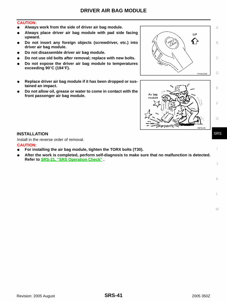
CAUTION:● Always work from the side of driver air bag module.● Always place driver air bag module with pad side facing
upward.● Do not insert any foreign objects (screwdriver, etc.) into
driver air bag module.● Do not disassemble driver air bag module.● Do not use old bolts after removal; replace with new bolts.● Do not expose the driver air bag module to temperatures
exceeding 90°C (194°F).
● Replace driver air bag module if it has been dropped or sus-tained an impact.
● Do not allow oil, grease or water to come in contact with thefront passenger air bag module.
INSTALLATIONInstall in the reverse order of removal.CAUTION:● For installing the air bag module, tighten the TORX bolts (T30).● After the work is completed, perform self-diagnosis to make sure that no malfunction is detected.
Refer to SRS-21, "SRS Operation Check" .
PHIA0164E
SBF814E

SRS-42
SPIRAL CABLE
Revision: 2005 August 2005 350Z
SPIRAL CABLE PFP:25554
Removal and Installation AHS00025
REMOVALCAUTION:Before servicing SRS, turn the ignition switch off, disconnect both battery cables and wait at least 3minutes.1. Remove driver air bag module. Refer to SRS-40, "Removal and Installation" .2. Set the steering wheel in the neutral position.3. Remove steering wheel nut.4. Remove combination meter assembly. Refer to DI-25, "Removal and Installation for Combination Meter" .5. Disconnect the spiral cable connector.
CAUTION:Do not tap or bump the steering wheel.
6. Remove steering wheel with steering wheel puller [A:ST27180001].CAUTION:Be careful not to over-tighten puller on steering wheel.
7. Loosen the spiral cable fixing screws, remove the spiral cable.CAUTION:● Do not disassemble spiral cable.● Do not apply lubricant to the spiral cable.
1. Steering wheel 2. Nut 3. Driver air bag module connector
4. Spiral cable 5. Scerw (Do not remove) 6. Wiper and washer switch
7. Screw 8. Steering column assembly 9. Combination meter
10. Lighting and turn signal switch
PHIA0713E
SGIA1323E

SPIRAL CABLE
SRS-43
C
D
E
F
G
I
J
K
L
M
A
B
SRS
Revision: 2005 August 2005 350Z
8. Remove the horn switch connector and then spiral cable con-nector.CAUTION:Also, with the steering linkage disconnected the cable maysnap by turning the steering wheel beyond the limited num-ber of turns.
INSTALLATIONInstall in the reverse order of removal.CAUTION:● The spiral cable may snap due to steering operation if the
cable is installed in an improper position.● Also, with the steering linkage disconnected the cable may
snap by turning the steering wheel beyond the limited num-ber of turns. The spiral cable can be turned counterclock-wise about 2.5 turns from the right end position.
● After the work is completed, perform self-diagnosis to makesure that no malfunction is detected. Refer to SRS-21, "SRSOperation Check" .
SHIA0193E
PHIA0180E

SRS-44
FRONT PASSENGER AIR BAG MODULE
Revision: 2005 August 2005 350Z
FRONT PASSENGER AIR BAG MODULE PFP:K8515
Removal and Installation AHS00026
REMOVALCAUTION:● Before servicing SRS, turn the ignition switch off, disconnect both battery cables and wait at least
3 minutes.● Always work from the side of or under front passenger air bag module.1. Remove instrument passenger panel lower. Refer to IP-13, "(M) Instrument Passenger Panel Lower" .2. Remove cluster lid C. Refer to IP-14, "(R) Cluster Lid C" .3. Disconnect passenger air bag connector.4. Remove special bolt, then remove front passenger air bag mod-
ule.
CAUTION:● Always place front passenger air bag module with caution
label side facing upward.● Do not insert any foreign objects (screwdriver, etc.) into
front passenger air bag module.● Do not disassemble front passenger air bag module.● Do not use old bolts after removal; replace with new bolts.
● Replace front passenger air bag module if it has beendropped or sustained an impact.
● Do not expose the front passenger air bag module to tem-peratures exceeding 90°C (194°F).
● Do not allow oil, grease or water to come in contact with thefront passenger air bag module.
● After front passenger air bag module inflates, the instru-ment panel assembly should be replaced.
INSTALLATIONInstall in the reverse order of removal.CAUTION:● Always work from the side of or under front passenger air bag module.● After the work is completed, perform self-diagnosis to make sure that no malfunction is detected.
Refer to SRS-21, "SRS Operation Check" .
PHIA0166E
PHIA0167E
SBF814E
SIDE CURTAIN AIR BAG MODULE (FOR COUPE)
SRS-45
C
D
E
F
G
I
J
K
L
M
A
B
SRS
Revision: 2005 August 2005 350Z
SIDE CURTAIN AIR BAG MODULE (FOR COUPE) PFP:985P0
Removal and Installation AHS00028
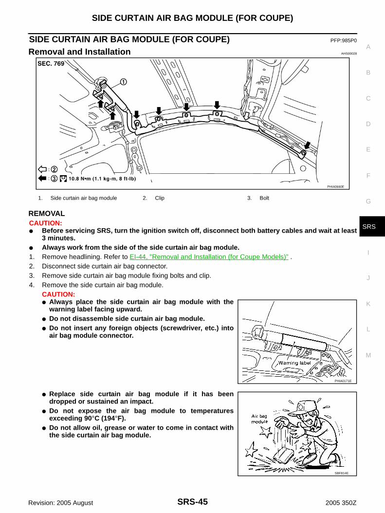
REMOVALCAUTION:● Before servicing SRS, turn the ignition switch off, disconnect both battery cables and wait at least
3 minutes.● Always work from the side of the side curtain air bag module.1. Remove headlining. Refer to EI-44, "Removal and Installation (for Coupe Models)" .2. Disconnect side curtain air bag connector.3. Remove side curtain air bag module fixing bolts and clip.4. Remove the side curtain air bag module.
CAUTION:● Always place the side curtain air bag module with the
warning label facing upward.● Do not disassemble side curtain air bag module.● Do not insert any foreign objects (screwdriver, etc.) into
air bag module connector.
● Replace side curtain air bag module if it has beendropped or sustained an impact.
● Do not expose the air bag module to temperaturesexceeding 90°C (194°F).
● Do not allow oil, grease or water to come in contact withthe side curtain air bag module.
PHIA0660E
1. Side curtain air bag module 2. Clip 3. Bolt
PHIA0171E
SBF814E

SRS-46
SIDE CURTAIN AIR BAG MODULE (FOR COUPE)
Revision: 2005 August 2005 350Z
INSTALLATIONInstall in the reverse order of removal.CAUTION:● Always work from the side of the side curtain air bag module.● After replacement of side curtain air bag module, perform self-diagnosis to make sure that no mal-
function is detected. Refer to SRS-21, "SRS Operation Check" .
CRASH ZONE SENSOR
SRS-47
C
D
E
F
G
I
J
K
L
M
A
B
SRS
Revision: 2005 August 2005 350Z
CRASH ZONE SENSOR PFP:98531
Removal and Installation AHS00029
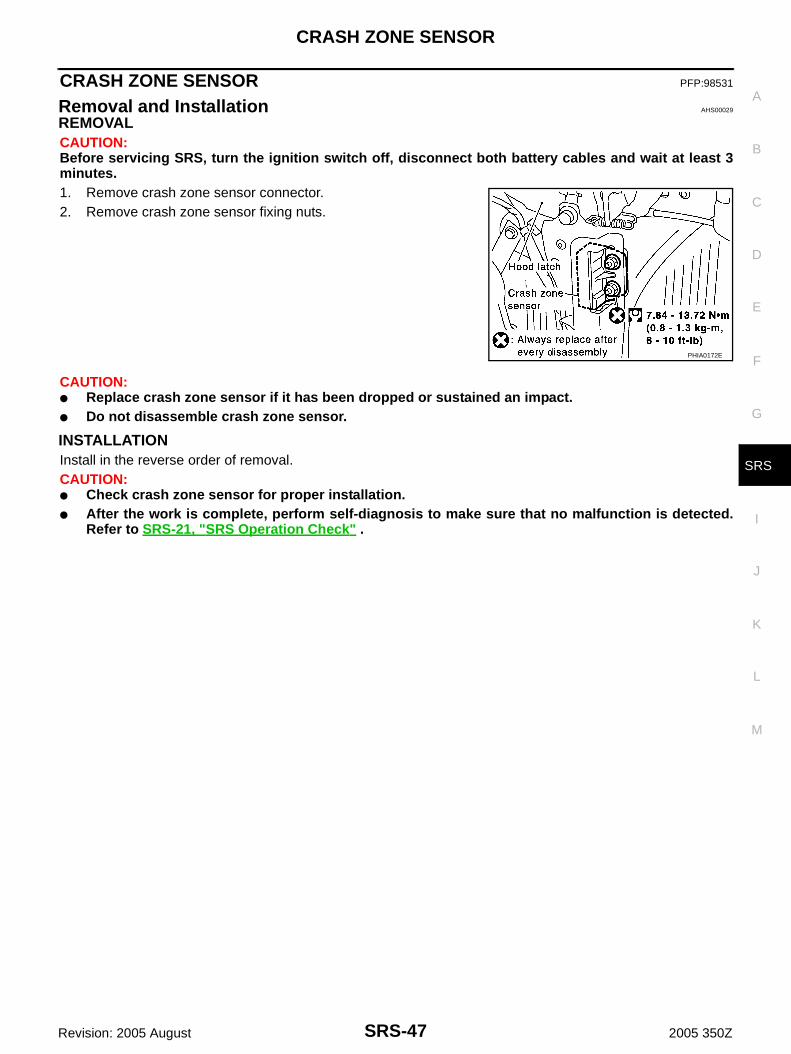
REMOVALCAUTION:Before servicing SRS, turn the ignition switch off, disconnect both battery cables and wait at least 3minutes.1. Remove crash zone sensor connector.2. Remove crash zone sensor fixing nuts.
CAUTION:● Replace crash zone sensor if it has been dropped or sustained an impact.● Do not disassemble crash zone sensor.
INSTALLATIONInstall in the reverse order of removal.CAUTION:● Check crash zone sensor for proper installation.● After the work is complete, perform self-diagnosis to make sure that no malfunction is detected.
Refer to SRS-21, "SRS Operation Check" .
PHIA0172E

SRS-48
SIDE AIR BAG (SATELLITE) SENSOR
Revision: 2005 August 2005 350Z
SIDE AIR BAG (SATELLITE) SENSOR PFP:98830
Removal and Installation AHS0002A
REMOVALCAUTION:Before servicing SRS, turn the ignition switch off, disconnect both battery cables and wait at least 3minutes.1. Remove seat belt pre-tensioner. Refer to SB-4, "Removal and Installation of Seat Belt (Coupe)" or SB-6,
"Removal and Installation of Seat Belt (Roadster)" .2. Remove side air bag (Satellite) sensor fixing nuts.3. Remove the side air bag (Satellite) sensor connector.
CAUTION:● Do not use old nuts; replace with new ones.● Check side air bag (Satellite) sensor to ensure it is free of deformities, dents, cracks or rust. If it
shows any visible signs of damage, replace it with new one.● Do not attempt to disassemble side air bag (Satellite) sensor.● Replace side air bag (Satellite) sensor if it has been dropped or sustained an impact.
INSTALLATIONInstall in the reverse order of removal.CAUTION:● Check side air bag (Satellite) sensor for proper installation.● After replacement of side air bag (Satellite) sensor, perform self-diagnosis to make sure that no
malfunction is detected. Refer to SRS-21, "SRS Operation Check" .
PHIA0176E

FRONT SEAT BELT PRE-TENSIONER
SRS-49
C
D
E
F
G
I
J
K
L
M
A
B
SRS
Revision: 2005 August 2005 350Z
FRONT SEAT BELT PRE-TENSIONER PFP:86884
Removal and Installation AHS0002B
For removal and installation procedures, refer to SB-4, "Removal and Installation of Seat Belt (Coupe)" or SB-6, "Removal and Installation of Seat Belt (Roadster)" .

SRS-50
DIAGNOSIS SENSOR UNIT
Revision: 2005 August 2005 350Z
DIAGNOSIS SENSOR UNIT PFP:28556
Removal and Installation AHS0002C
REMOVALCAUTION:Before servicing SRS, turn the ignition switch off, disconnect both battery cables and wait at least 3minutes.1. Disconnect each harness connector for the air bag module and seat belt pre-tensioner.2. Remove center console. Refer to IP-11, "Removal and Installation" .3. Disconnect diagnosis sensor unit connector.4. Remove fixing bolts from the diagnosis sensor unit.
CAUTION:● Do not use old bolts. Replace with new ones.● Check diagnosis sensor unit bracket to ensure it is free of deformities, dents, cracks or rust. If it
shows any visible signs of damage, replace with new one.● Replace diagnosis sensor unit if it has been dropped or sustained an impact.
INSTALLATIONInstall in the reverse order of removal.CAUTION:● Check the diagnosis sensor unit for proper installation.● After replacement of diagnosis sensor unit, perform self-diagnosis to make sure that no malfunc-
tion is detected. Refer to SRS-21, "SRS Operation Check" .
ECU DISCRIMINATED NO.After replacing the diagnosis sensor unit, make sure that the diagnosis sensor unit identification is correct forthe vehicle as equipped.
Hexagon head bolt: 24.5 N·m (2.5 kg-m, 18 ft-lb)
Ground bolt: 6.9 N·m (0.7 kg-m, 61 in-lb)
PHIA0463E
Model Specification ECU DISCRIMINATED No.
Coupe
Models with driver and passenger air bags and seat belt pre-tensioner FA51
Models with driver and passenger air bags, seat belt pre-tensioner, side air bags and curtain air bags
FA53
RoadsterModels with driver and passenger air bags and seat belt pre-tensioner FA86
Models with driver and passenger air bags, seat belt pre-tensioner and side air bags FA52

COLLISION DIAGNOSIS
SRS-51
C
D
E
F
G
I
J
K
L
M
A
B
SRS
Revision: 2005 August 2005 350Z
COLLISION DIAGNOSIS PFP:00015
For Frontal Collision AHS0002E
To repair the SRS, perform the following steps.When SRS (except the front side air bag and side curtain air bag modules) is activated in a collision:1. Replace the diagnosis sensor unit.2. Remove the air bag modules (except the front side air bag modules and side curtain air bag modules),
crash zone sensor assembly, bracket and seat belt pre-tensioner assemblies.3. Check the SRS components using the table below:– Replace any SRS components showing visible signs of damage (dents, cracks and deformation).4. Install new air bag modules (except the front side air bag modules and side curtain air bag modules) crash
zone sensor assembly, bracket and seat belt pre-tensioner assemblies.5. Perform self-diagnosis using CONSULT-II or “AIR BAG” warning lamp. Refer to SRS-21, "SRS Operation
Check" for details. Ensure entire SRS operates properly.When SRS is not activated in a collision:1. Check the SRS components using the table below:– Replace any SRS components showing visible signs of damage (dents, cracks and deformation).2. Perform self-diagnosis using CONSULT-II or “AIR BAG” warning lamp. Refer to SRS-21, "SRS Operation
Check" for details. Ensure entire SRS operates properly.When only one front air bag module is activated in a collision:1. Replace the following components:– Diagnosis sensor unit– Crash zone sensor– Activated front air bag and seat belt pre-tensioner.2. Check the other SRS components using the table below. (Refer to “SRS is NOT activated”.)– Replace any SRS components showing visible signs of damage (dents, cracks and deformation).3. Perform self-diagnosis using CONSULT-II or “AIR BAG” warning lamp. Refer to SRS-21, "SRS Operation
Check" for details. Ensure entire SRS operates properly.Only one front air bag may inflate a crash, depending on the crash severity and whether the front occupantsare belted or unbelted. This does not indicate improper performance of the system. Perform self-diagnosis tomake sure the entire SRS operates properly.
SRS INSPECTION (FOR FRONTAL COLLISION)Part SRS is activated SRS is NOT activated
Driver airbag module
If the Driver airbag has deployed:REPLACE.Install with new fasteners.
If the Driver air bag has NOT been activated:[same text as in current manual]
Passenger front airbag module
If the Passenger front airbag has deployed: REPLACE.Install with new fasteners.
If the Passenger front air bag has NOT been activated:[same text as in current manual]
Crash zone sensor
If any of the front airbags or seat belt pre-tensionsers have been activated:REPLACE the crash zone sensor and bracket with new fasteners.
If the front airbags or seat belt pre-tensionsers have NOTbeen activated:[same text as in current manual]
Seat belt pre-ten-sioner assemblies
If the driver or passenger Seat belt pre-ten-sioner has been activated:REPLACE the seat belt pre-tensionerassemblies with new fasteners.
If the pre-tensioners have NOT been activated:[same text as in current manual]
Diagnosis sensor unit
If any of the SRS components have beenactivated:REPLACE the Diagnosis sensor unit.Install with new fasteners.
If none of the SRS components have been activated:[same text as in current manual]

SRS-52
COLLISION DIAGNOSIS
Revision: 2005 August 2005 350Z
Steering wheel [same text as in current manual]
Spiral cable If the Driver airbag has deployed:REPLACE the spiral cable.
If the Driver airbag has not deployed:[same text as in current manual]
Harness and con-nectors
1. Check connectors for poor connection, damage, and terminals for deformities.
2. Check harness for binding, chafing, cuts, or deformities.
3. If no damage is found, reinstall the harness and connectors.
4. If damaged—REPLACE damaged section of harness. Do not repair, splice or modify any SRS harness.
Instrument panel 1. Visually check instrument panel for damage.
2. If no damage is found, reinstall the instrument panel.
3. If damaged—REPLACE the instrument panel with bolts.
Part SRS is activated SRS is NOT activated

COLLISION DIAGNOSIS
SRS-53
C
D
E
F
G
I
J
K
L
M
A
B
SRS
Revision: 2005 August 2005 350Z
For Side Collision AHS0002F
WHEN THE SIDE AIR BAG IS ACTIVATED IN THE SIDE COLLISION:1. Replace the following components:– All parts of front seatback (including front seatback frame) with front side air bag module (on the side on
which front side air bag is activated)– Curtain air bag module (on the side on which side curtain air bag is activated)– Diagnosis sensor unit– Satellite sensor (on the side on which side air bag and side curtain air bag is activated)2. Check the SRS components and the related parts using the following table.– Replace any SRS components and the related parts showing visible signs of damage (dents, cracks,
deformation).3. Perform self-diagnosis using CONSULT-II or “AIR BAG” warning lamp. Refer to SRS-21, "SRS Operation
Check" . Ensure entire SRS operates properly.
WHEN SRS IS NOT ACTIVATED IN THE SIDE COLLISION:1. Check the SRS components and the related parts using the following table.– Replace any SRS components and the related parts showing visible signs of damage (dents, cracks,
deformation).2. Perform self-diagnosis using CONSULT-II or “AIR BAG” warning lamp. Refer to SRS-21, "SRS Operation
Check" . Ensure entire SRS operates properly.
SRS INSPECTION (FOR SIDE COLLISION)
PartFront side air bag and side curtain air bag is
activatedFront side air bag and side curtain air bag is NOT activated
(LH or RH) side cur-tain air bag module*
Replace the side cur-tain air bag module.(Repair the center pil-lar inner, etc. before installing new one if damaged.)
1. Check for visible signs of damage (dents, tears, deformation) of the center pillar on the collision side.
2. If damaged— Remove the side curtain air bag module.
3. Check for visible signs of damaged (tears etc.) of the side curtain air bag module.
4. Check harness and connectors for damage, and terminals for deformities.
5. If no damage is found, reinstall the side curtain air bag module with new bolts.
6. If damaged—REPLACE the side curtain air bag module with new bolts.
Front (LH or RH) side air bag module
REPLACE all parts of seatback with deployed front side air bag module.
1. Check for visible signs of damage (dents, tears, deformation) of the seat back on the collision side.
2. Check harness and connectors for damage, and terminals for deformities.
3. If no damage is found, reinstall the front seatback assembly.
4. If damaged—REPLACE the front seatback assembly.
(LH or RH) side air bag (Satellite) sensor
REPLACE the side air bag (Satellite) sen-sor on the collision side with new nuts.(Repair the center pil-lar inner, etc. before installing new one if damaged.)
1. Remove the side air bag (Satellite) sensor on the collision side. Check harness connectors for damage, terminals for deformities, and harness for binding.
2. Check for visible signs of damage (dents, cracks, deformation) of the side air bag (Satellite) sensor.
3. Install the side air bag (Satellite) sensor to check fit.
4. If no damage is found, reinstall the side sir bag (Satellite) sensor with new nuts.
5. If damaged—REPLACE the side air bag (Satellite) sensor with new nuts.
Diagnosis sensor unit REPLACE the diag-nosis sensor unit with the new bolts.
1. Check case and bracket for dents, cracks or deformities.
2. Check connectors for damage, and terminals for deformities.
3. If no damage is found, reinstall the diagnosis sensor unit with new bolts and ground bolt.
4. If damaged—REPLACE the diagnosis sensor unit with new bolts and ground bolt.

SRS-54
COLLISION DIAGNOSIS
Revision: 2005 August 2005 350Z
*: For coupe
Seat belt pre-ten-sioner assembly
1. Check if the seat belt can be extended smoothly.If the seat belt cannot be extended smoothly,
– Check for deformities of the center pillar inner.
– If the center pillar inner has no damage, REPLACE the seat belt pre-tensioner assembly.
2. Remove the seat belt pre-tensioner assembly on the collision side. Check harness cover and connectors for damage, terminals for deformities, and harness for binding.
3. Check for visible signs of damage (dents, cracks, deformation) of the seat belt pre-tensioner assembly.
4. Check seat belt adjuster for damage.
5. If no damage is found, reinstall the seat belt pre-tensioner assembly.
6. If damaged—REPLACE the seat belt pre-tensioner assembly with new bolts.
Seat with front side air bag
REPLACE all parts of front seatback (including front seat-back frame)
1. Visually check the seat on the collision side.
2. Remove the seat on the collision side and check the following for damage and deformities.
– Harness, connectors and terminals
– Frame and recliner (for front and rear seat), and also adjuster and slides (for front seat)
3. If no damage is found, reinstall the seat.
4. If damaged—REPLACE the damaged seat parts using new bolts.
Center inner pillar 1. Check the center inner pillar on the collision side for damage (dents, cracks, deformation).
2. If damaged—REPAIR the center inner pillar.
Trim/headlining* 1. Check for visible signs of damage (dents, cracks, deformation) of the interior trim on the collision side.
2. If damaged—REPLACE the damaged trim parts.
PartFront side air bag and side curtain air bag is
activatedFront side air bag and side curtain air bag is NOT activated