
Supplemental Notice of Proposed Rulemaking; 49 CFR Part ...€¦ · January 24, 2011 The Honorable...
47
January 24, 2011 The Honorable David L. Strickland Administrator National Highway Traffic Safety Administration 1200 New Jersey Avenue, SE Washington, DC 20590 Supplemental Notice of Proposed Rulemaking; 49 CFR Part 571, Child Restraint Systems, Hybrid III 10-Year-Old Child Test Dummy; Docket No. NHTSA-2010-0158 Dear Administrator Strickland: The Insurance Institute for Highway Safety (IIHS) welcomes the opportunity to comment on the National Highway Traffic Safety Administration’s (NHTSA) Supplemental Notice of Proposed Rulemaking (SNPRM) concerning proposed changes to Federal Motor Vehicle Safety Standard (FMVSS) 213. We strongly encourage the agency to incorporate into its new regulation belt fit criteria for belt positioning booster seats. The primary purpose of booster seats is to correctly position vehicle lap/shoulder belts on the smaller anatomy of children, typically children ages 4-10. Given the wide range of belt configurations in the rear seats of passenger vehicles, providing good lap/shoulder belt fit across the vehicle fleet is a challenging but essential requirement for boosters. Without a booster seat, the lap belt is positioned above the pelvis, increasing the risk of submarining and abdominal injury (Nance et al., 2004). A well-designed booster also positions the shoulder belt across the middle of the shoulder. Without a booster seat shoulder belt guide, the belt may be positioned too low on a child’s torso, resulting in sub-optimal torso restraint. In other cases, the shoulder belt may be positioned on the child’s face or neck, resulting in discomfort that may cause a child to reposition the belt under the arm or behind the back. Booster seats require thoughtful design to ensure good lap/shoulder belt fit across the full range of passenger vehicles, but not all currently available boosters achieve this. Moreover, FMVSS 213 does not include any metric to ensure that booster seats properly position lap/shoulder belts, but this would be accomplished by the incorporation of static belt fit criteria. IIHS collaborated with the University of Michigan Transportation Research Institute (UMTRI) to develop a static belt fit measurement protocol for booster seats (Reed et al., 2009) and used it to rate boosters available on the market in 2008 (IIHS, 2008). The protocol evaluated lap/shoulder belt fit on a Hybrid III 6-year-old child dummy across a broad range of seat belt anchorage locations, and the belt scores were combined to determine an overall rating for the booster. IIHS subsequently refined the protocol to improve repeatability and reproducibility, particularly focusing on issues related to shoulder belt measurement (IIHS, 2009b, 2009c). In the IIHS rating system, Best Bet boosters should provide good lap/shoulder belt fit for typical 4-8-year-old children in almost any vehicle. Good Bet boosters provide optimal fit in almost as many vehicles as Best Bet seats. Boosters that do not provide acceptable placement for either the lap or shoulder belt in any of the belt configurations are rated as Not Recommended. The remaining seats can provide good protection for some children in some vehicles, but provide unacceptable protection in other vehicles In 2008, almost one-third of the boosters rated were classified as Not Recommended. IIHS updated its booster ratings in 2009 and again in 2010 (IIHS, 2009a, 2010), and significant improvements in booster designs were evident. In 2010, the proportion of boosters on the market rated as Best Bet and Good Bet increased dramatically to 87 percent, with only 11 percent of boosters rated as Not Recommended. Several manufacturers have used the IIHS belt fit protocol during their booster design phases, resulting in
Transcript of Supplemental Notice of Proposed Rulemaking; 49 CFR Part ...€¦ · January 24, 2011 The Honorable...

January 24, 2011
The Honorable David L. Strickland Administrator National Highway Traffic Safety Administration 1200 New Jersey Avenue, SE Washington, DC 20590
Supplemental Notice of Proposed Rulemaking; 49 CFR Part 571, Child Restraint Systems, Hybrid III 10-Year-Old Child Test Dummy; Docket No. NHTSA-2010-0158
Dear Administrator Strickland:
The Insurance Institute for Highway Safety (IIHS) welcomes the opportunity to comment on the National Highway Traffic Safety Administration’s (NHTSA) Supplemental Notice of Proposed Rulemaking (SNPRM) concerning proposed changes to Federal Motor Vehicle Safety Standard (FMVSS) 213. We strongly encourage the agency to incorporate into its new regulation belt fit criteria for belt positioning booster seats.
The primary purpose of booster seats is to correctly position vehicle lap/shoulder belts on the smaller anatomy of children, typically children ages 4-10. Given the wide range of belt configurations in the rear seats of passenger vehicles, providing good lap/shoulder belt fit across the vehicle fleet is a challenging but essential requirement for boosters. Without a booster seat, the lap belt is positioned above the pelvis, increasing the risk of submarining and abdominal injury (Nance et al., 2004). A well-designed booster also positions the shoulder belt across the middle of the shoulder. Without a booster seat shoulder belt guide, the belt may be positioned too low on a child’s torso, resulting in sub-optimal torso restraint. In other cases, the shoulder belt may be positioned on the child’s face or neck, resulting in discomfort that may cause a child to reposition the belt under the arm or behind the back. Booster seats require thoughtful design to ensure good lap/shoulder belt fit across the full range of passenger vehicles, but not all currently available boosters achieve this. Moreover, FMVSS 213 does not include any metric to ensure that booster seats properly position lap/shoulder belts, but this would be accomplished by the incorporation of static belt fit criteria.
IIHS collaborated with the University of Michigan Transportation Research Institute (UMTRI) to develop a static belt fit measurement protocol for booster seats (Reed et al., 2009) and used it to rate boosters available on the market in 2008 (IIHS, 2008). The protocol evaluated lap/shoulder belt fit on a Hybrid III 6-year-old child dummy across a broad range of seat belt anchorage locations, and the belt scores were combined to determine an overall rating for the booster. IIHS subsequently refined the protocol to improve repeatability and reproducibility, particularly focusing on issues related to shoulder belt measurement (IIHS, 2009b, 2009c). In the IIHS rating system, Best Bet boosters should provide good lap/shoulder belt fit for typical 4-8-year-old children in almost any vehicle. Good Bet boosters provide optimal fit in almost as many vehicles as Best Bet seats. Boosters that do not provide acceptable placement for either the lap or shoulder belt in any of the belt configurations are rated as Not Recommended. The remaining seats can provide good protection for some children in some vehicles, but provide unacceptable protection in other vehicles
In 2008, almost one-third of the boosters rated were classified as Not Recommended. IIHS updated its booster ratings in 2009 and again in 2010 (IIHS, 2009a, 2010), and significant improvements in booster designs were evident. In 2010, the proportion of boosters on the market rated as Best Bet and Good Bet increased dramatically to 87 percent, with only 11 percent of boosters rated as Not Recommended. Several manufacturers have used the IIHS belt fit protocol during their booster design phases, resulting in

David Strickland January 24, 2011 Page 2 good designs when the seats went to market. Manufacturers also have modified already available boosters to improve belt fit. All of these improvements are a direct result of providing the booster manufacturers with an established protocol for designing and evaluating their boosters.
NHTSA states in its SNPRM that it is “not proposing belt fit criteria at this time” because the “repeatability and reproducibility of the belt fit procedure does not seem robust enough to implement in the FMVSS No. 213.” The agency’s concerns primarily are associated with differences in dummy jackets and friction issues between the belt and dummy’s chest that arose using the original UMTRI protocol from 2008. The refined IIHS (2009b) protocol resolved these issues to improve repeatability and reproducibility and specifically addressed the dummy jacket and friction concerns. By using a new test fixture, standardized hardware and components, and improved techniques to measure shoulder belt fit and derive a score, IIHS is confident the new protocol results in improved repeatability and reproducibility.
FMVSS 213 should include an evaluation of the primary function of booster seats: the ability to correctly position vehicle lap/shoulder belts on the smaller anatomy of children across a range of vehicle anchorage locations. This cannot be accomplished practically using dynamic tests. IIHS has demonstrated that federally compliant booster seats offer a wide range of belt fit performance, with some poor enough to be Not Recommended by IIHS. Booster seat manufacturers have shown they can improve the belt fit of their boosters using the modified static belt fit measurement protocol, and NHTSA should incorporate the protocol into its new regulation without delay.
Sincerely, Christopher P. Sherwood, M.S. Senior Research Engineer cc: Docket Clerk, Docket No. NHTSA-2010-0158
Attachments
Insurance Institute for Highway Safety. 2009b. Booster seat belt fit evaluation protocol (ver. I). Arlington, VA.
Insurance Institute for Highway Safety. 2009c. Booster test fixture drawing package. Arlington, VA.
References
Insurance Institute for Highway Safety. 2008. Special issue: booster seats. Status Report 43(8). Arlington, VA.
Insurance Institute for Highway Safety. 2009a. Status Report 44(11). Arlington, VA.
Insurance Institute for Highway Safety. 2009b. Booster seat belt fit evaluation protocol (ver. I). Arlington, VA.
Insurance Institute for Highway Safety. 2009c. Booster text fixture drawing package. Arlington, VA.
Insurance Institute for Highway Safety. 2010. Status Report 45(9). Arlington, VA.
Nance, M.L.; Lutz, N.; Arbogast, K.A.; Cornejo, R.A.; Kallan, M.J.; Winston, F.K.; and Durbin, D.R. 2004. Optimal restraint reduces the risk of abdominal injury in children involved in motor vehicle crashes. Annals of Surgery 239:127-31.
Reed, M.P.; Ebert, S.M.; Sherwood, C.P.; Klinich, K.D.; and Manary, M.A. 2009. Evaluation of the static belt fit provided by belt-positioning booster seats. Accident Analysis and Prevention 41:598-607.

Booster Seat Belt Fit Evaluation Protocol (Version I)
December 2009

2009 Insu1005 N. Gle
OVERVI
The objecquantify tpotential lmethod uschildren. Transport
TEST FIX
Test Seat
The test fiwith adjus
The seat bbottom ancm long (mbottom lencushion an
The seat bFoam A “213. SourAppendixof 1.3 cm
urance Institute febe Road, Arling
IEW
ctive of the Inthe ability of blap and shoulsed to obtain The protocol
tation Researc
XTURE
t
fixture (Figurestable belt an
bottom is 51 ±nd seat back) measured frongth is greatend seat back a
bottom and se“Extra Firm Hrces for this f
x. Both cushio. Each cushio
for Highway Safgton, VA 22201.
nsurance Institbooster seats lder belt anchlap and shoull is based largch Institute, w
e 1) consists ochorage locat
± 1 cm long (and is reclinem the seat big
er, where it exare 42 ± 1 cm
FigurTest Fix
eat back are bHigh Density Gfoam, as well ons are suppoon then is cov
fety All rights reser
tute for Highwto provide prorage locatiolder belt score
gely on researwith some mo
of a representtions.
measured froed 15 ± 1 degrght) and is rextends below
m wide.
re 1 xture
both constructGrade” foam as other mate
orted by a wovered in a mar
rved.
way Safety’s roper seat beltns. The purpes that represrch conductedodifications m
tative test seat
om the seat bigrees from horclined 23 ± 1the bottom su
ted from a 5 cspecified in F
erials and supod (plywood rine vinyl (se
Boo
booster seat bt positions on
pose of this prent the qualit
d by the Univemade to standa
t and a three-
ght, defined arizontal (Figu degrees fromurface of the s
FigTes
cm thick polyuFederal Motopplies used in
or MDF) secee Appendix).
oster Seat Belt F
belt fit evaluan children, acrrotocol is to dty of seat belt ersity of Mich
ardize the pro
point lap/sho
as the intersecure 2). The sem vertical. Thseat back. Bo
gure 2st Seat
urethane foamor Vehicle Saf
this protocolction with a m
Fit Evaluation PrDecember 200
ation programross a range odescribe the
locations on higan cedure.
ulder belt sys
ction of the seeat back is 61 he total seat oth the seat
m, identical tofety Standard , are listed in
minimum thick
rotocol 09 — 1
m is to of
stem
eat ± 1
o the No. the
kness

2009 Insurance Institute for Highway Safety Booster Seat Belt Fit Evaluation Protocol 1005 N. Glebe Road, Arlington, VA 22201. All rights reserved. December 2009 — 2
The coordinate system for the test rig is shown in Figure 1. The positive X axis points toward the rear of the seat, the positive Y axis points toward the right side of the seat, and the positive Z axis points upward vertically. The origin for this reference frame is located at the resulting H-point location for the seat (SAE J826 MAR2008), at the seat centerline. Once the H-point location was determined for the test seat during the design process, a simplified test device was created to locate this same origin. For the purposes of the official protocol, this simplified test device (Booster Seat H-Point Origin Device, or BPOD) is used to locate the origin. Drawings for BPOD are located in the Appendix.
To determine the origin of the test fixture, place the BPOD on the seat cushion forward of the seat bight, and slowly slide it rearward until contact is made with the seat back. Use a force gauge to push the BPOD into the seat, parallel to the seat cushion at a location approximately 6 cm above the base, at a force of 40 pounds. The position of the BPOD reference point defines the location of the origin.
Seat Belt System
The frame used to support the test seat also supports the anchorage locations for the seat belt system. Any rigid frame can be used to support the test seat and seat belt system. These anchorages must be adjustable because they are moved to different positions during testing. Coordinates for the anchorage locations are listed in Table 1. The seat belt system (see Appendix) includes an inboard female buckle, webbing extender, retractor, D-ring anchor with bolt, and outboard end fitting. The test fixture was based on the geometry of a right, rear passenger seat. The right side of the seat, with D-ring and retractor, is considered to be the outboard side, whereas the left side of the seat is referred to as the inboard side.
Table 1Seat Belt System Anchor Coordinates (mm)
Anchorage Location X Y Z Inboard Maximum angle (83°) 15 -250 -125
Minimum angle (41°) 144 -250 -125 Outboard Maximum angle (68°) 57 330 -141
Minimum angle (35°) 201 330 -141 D-ring Fore/outboard/low 258 312 524
Aft/inboard/high 560 214 668
The coordinates for each position (lap belt maximum vs. minimum angles, D-ring fore/outboard/ low vs. aft/inboard/high) are based on the range of positions found in current model test vehicles, which approximates the full range allowed by federal standards. The angle of the lap belt is defined as the angle (with respect to horizontal) of a line from the seat H-point to the anchorage location.
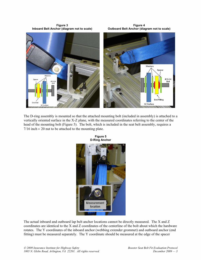
The female buckle is attached to the webbing extender with a 3/8 inch bolt, tightened sufficiently to prevent rotation between these two pieces, with the long axis of the buckle in line with the two grommets. The other end of the webbing extender is attached to the test fixture at a vertically oriented surface in the X-Z plane (see Figure 3). A #10-24 bolt passes through the grommet and serves as the axis around which the webbing extender can rotate. A spacer is required inside the grommet to (a) prevent the nut from being tightened to the point of preventing the webbing from rotating and (b) reduce the amount of play between the grommet and the bolt. The spacer should have a length of 0.22 ± 0.02 inch, an ID of 0.228 ± 0.01 inch, and an OD of 0.36 ± 0.02 inch. Washers are located on either side of the spacer.
The outboard lap belt anchorage has a metal end fitting that is attached to the test fixture at a vertically oriented surface in the X-Z plane (Figure 4) with a #10-24 bolt. As on the inboard side, a spacer is required between the end fitting and the bolt. The spacer should have a length of 0.22 ± 0.02 inch, an ID of 0.228 ± 0.01 inch, and an OD of 0.5 ± 0.02 inch. Washers are located on either side of the spacer.
2009 Insurance Institute for Highway Safety Booster Seat Belt Fit Evaluation Protocol 1005 N. Glebe Road, Arlington, VA 22201. All rights reserved. December 2009 — 3
Figure 3 Inboard Belt Anchor (diagram not to scale)
Figure 4 Outboard Belt Anchor (diagram not to scale)
The D-ring assembly is mounted so that the attached mounting bolt (included in assembly) is attached to a vertically oriented surface in the X-Z plane, with the measured coordinates referring to the center of the head of the mounting bolt (Figure 5). The bolt, which is included in the seat belt assembly, requires a 7/16 inch × 20 nut to be attached to the mounting plate.
Figure 5 D-Ring Anchor
The actual inboard and outboard lap belt anchor locations cannot be directly measured. The X and Z coordinates are identical to the X and Z coordinates of the centerline of the bolt about which the hardware rotates. The Y coordinates of the inboard anchor (webbing extender grommet) and outboard anchor (end fitting) must be measured separately. The Y coordinate should be measured at the edge of the spacer

2009 Insurance Institute for Highway Safety Booster Seat Belt Fit Evaluation Protocol 1005 N. Glebe Road, Arlington, VA 22201. All rights reserved. December 2009 — 4
closest to the seat centerline (also the face of the washer that contacts the spacer on this edge). The coordinates for the D-ring anchorage refer to the center of the mounting bolt. After purchase of the system, a punch (or other method) should be used to create a permanent location at the center face of the bolt for measurement (Figure 5). Each booster is tested in four combinations of lap and shoulder belt anchor locations. The test matrix is shown below in Table 2.
Table 2Test Matrix
Condition Description (Lap/Shoulder) Lap – Inboard Lap – Outboard Shoulder
1 Minimum/Fore Minimum angle 41° Minimum angle 35° Fore/outboard/low 2 Maximum/Fore Maximum angle 83° Maximum angle 68° Fore/outboard/low 3 Minimum/Aft Minimum angle 41° Minimum angle 35° Aft/inboard/high 4 Maximum/Aft Maximum angle 83° Maximum angle 68° Aft/inboard/high
ANTHROPOMORPHIC TEST DEVICE
Prepare ATD
A Hybrid III 6-year-old anthropomorphic test device (ATD) is used in this procedure to represent a booster-age child. No instrumentation is required.
ATD Head – The center of gravity locations on each side of the ATD’s head should be noted and marked with test stickers. This procedure should only need to be performed once.
ATD Pelvis – An important aspect of the procedure involves locating the reference points on the surface of the ATD’s pelvis. Reference points only need to be located and marked once (with occasional verification that the ATD’s pelvis skin has not shifted with respect to the rigid base).
1.1. Remove the ATD abdominal insert.
1.2. Set the ATD on a rigid surface and secure it in a stationary position. Ratchet straps are useful in attaching the ATD to the test surface to prevent movement. Because the orientation of the reference frame is determined by the location of the top surface of the pelvis (Figure 6), the ATD’s position in space is not critical, as long as it does not move.
Figure 6 Pelvic Reference Frame

2009 Insurance Institute for Highway Safety Booster Seat Belt Fit Evaluation Protocol 1005 N. Glebe Road, Arlington, VA 22201. All rights reserved. December 2009 — 5
1.3. Insert the H-point offset tools (see Appendix) in each side of the ATD’s pelvis. The purpose of the tools is (a) to allow measurement of the ATD’s pelvis angle and H-point location and (b) to allow use of a coordinate measuring machine (CMM) to measure the lap belt position with respect to the pelvis (and lap belt score). If only hand measurements are used (discussed later in the protocol), the H-point tools are not necessary.
1.4. The coordinate system for the pelvis is identical to the test fixture (X rearward, Y rightward, Z upward). The X-Y plane is defined as the top surface of the pelvis (rigid metal base). The origin is located at the intersection of this top surface of the pelvis and the lumbar load cell (or structural replacement), at the ATD’s centerline (measured as the midpoint of the lumbar load cell) (Figure 6).
1.5. Once the reference frame has been determined, the ATD equivalent pubic symphysis point and anterior superior iliac spines reference points are projected onto the front surface of the molded ATD pelvis.
1.5.1. Pubic symphysis (PS-ATD) – The point on the front surface of the ATD’s pelvis skin with a Z value of 0 (same plane as the rigid base of the pelvis) and a Y value of 0 (midpoint of the ATD). Mark this point on the ATD skin (Figure 7).
1.5.2. Anterior superior iliac spines (ASIS-ATD) – The actual ASIS on the rigid ATD pelvis must be located first. The left ASIS landmark is shown in Figure 7. The upper edge should have consistent Y and Z values along its length. Only measure the top edge, staying rearward of the front corner. The point on the front surface of the ATD pelvis with the same Y and Z values represents the ASIS-ATD. Mark these points on the ATD skin.
Figure 7 ATD Anterior Superior Iliac Spines and Pubic Symphysis
1.5.3. Additional points should be placed on the ATD skin with the same Y values as the ASIS-ATD, from the anterior superior edge of the pelvis to the thigh/pelvis gap. When the lap belt is digitized later in the protocol, the belt is measured at the lateral location where it crosses this X-Z plane.
1.6. Reference points on the hip-offset tools should be digitized at this time, if a coordinate measuring machine (CMM) is to be used to record measurement data. When the lap belt position is digitized later in the protocol, these hip-offset reference points are used to determine the correct pelvis reference frame for taking lap belt measurements.

2009 Insurance Institute for Highway Safety Booster Seat Belt Fit Evaluation Protocol 1005 N. Glebe Road, Arlington, VA 22201. All rights reserved. December 2009 — 6
Final ATD Setup
2.1. All limb joints should be tightened to just greater than 1 g so that the limbs do not rotate after being positioned, but do not require excessive force to change position.
2.2. The ATD is tested without clothing. Make sure the abdominal insert has been installed.
2.3. The ATD’s design results in a large gap between the thigh flesh and pelvis flesh, which can result in nonbiofidelic lap belt positions. This is corrected by adding a lap shield to provide a smooth surface from the upper surface of the pelvis to the mid-thigh region. The lap shield material and dimensions are listed in the Appendix. One purpose of the lap shield is to provide a low-friction surface for better positioning of the lap belt. A thin layer of baby powder should be added to the lap shield surface prior to use.
2.4. With the ATD seated upright on a flat surface, apply double-sided tape to the surface of the lap shield that will be in contact with the pelvis (Figure 8). The top edge of the lap shield should be aligned with the anterior superior edge of the ATD pelvis skin. It also may be useful to cut small holes (approximately 5 mm in diameter) where the lap shield covers the left and right ASIS. These provide a direct view of the ASIS during hand measurements of the lap belt position.
2.5. The lap shield has a tendency to separate from the pelvis even when taped, due to the low friction coefficient of the silicone. Additional tape can be used to attach the shield to the pelvis, although the tape should be applied in areas that are not in contact with the lap belt. Flexible measuring tape also can be applied, at the lateral location of the ASIS to assist in hand measurements (Figure 8).
2.6. To better mimic how real children sit in vehicle seats (Reed et al., 2006), a pelvis positioning pad is attached to the rear surface of the pelvis. The pelvis positioning pad material and dimensions are listed in the Appendix. Using double sided tape, position the pad in a centered location on the posterior of the ATD pelvis, with the top edge of the foam aligned with the superior edge of the ATD pelvis skin (Figure 9).
Figure 8 Lap Shield
Figure 9 Pelvis Positioning Pad
2.7. To reduce friction between the shoulder belt and ATD chest jacket during the procedure, a thin Teflon sheet (see Appendix) is taped to the front edge of the ATD chest jacket. Double sided tape should be placed in the approximate location of the chest reference point to adhere the Teflon sheet

2009 Insurance Institute for Highway Safety Booster Seat Belt Fit Evaluation Protocol 1005 N. Glebe Road, Arlington, VA 22201. All rights reserved. December 2009 — 7
to the chest jacket. Additional one-sided tape can be used as necessary at the edges of the Teflon sheet (Figure 10).
2.8. The chest reference point is located on the front of the ATD chest jacket, but its position is based on the location of the ATD spine.
2.8.1. Place the ATD torso in an upright position, defined as the superior face of the lower neck load cell (or structural replacement) being horizontal. The orientation of the reference frame is identical to that for the test fixture (X-Y plane parallel to the superior face of the load cell), and the origin is the posterior superior edge of the load cell, at the midline of the ATD (Figure 11). (Note that when using a CMM, the torso position does not need to be exactly vertical because the reference frame is determined by the orientation of the lower neck load cell. If a CMM is not used, the ATD spine may need to be more precisely positioned to accurately position the chest reference point).
Figure 10 Chest Reference Point and Tape
Figure 11 ATD Reference Frame for Locating
Chest Reference Point
2.8.2. A thin aluminum (recovery) plate can be attached to the rear surface of the lower neck bracket, projecting above the top surface, to assist in establishing the correct reference frame (Figure 12). During the evaluation process, it is difficult to reach the neck bracket to establish the correct reference frame. The neck bracket recovery plate provides easier access to digitizing points that can be used to recover the reference frame when the chest reference point is verified.

2009 Insurance Institute for Highway Safety Booster Seat Belt Fit Evaluation Protocol 1005 N. Glebe Road, Arlington, VA 22201. All rights reserved. December 2009 — 8
Figure 12 Neck Bracket Recovery Plate
2.9. With the chest jacket properly installed (snugly pushed in the inferior and posterior directions), the chest reference point is defined as the location on the anterior surface of the chest jacket, at the ATD centerline, which has a Z coordinate of 0 (same plane as the load cell surface). The coordinate of this point should be (-110 ± 5, 0, 0 mm).
2.10. To ensure consistency among different chest jackets, a second reference point should be checked, verifying the chest jacket coordinates at the ATD shoulder. At the midline of the ATD neck (approximate X value of 53 mm ), measure laterally 4 cm (from the outer edge of the neck). The top surface of the chest jacket at this location should have a value of (-53, 72, 10 ± 5 mm).
2.10.1. If the ATD chest jacket does not meet these requirements, spacers must be placed on top of the chest bib (below the chest jacket). An example of the spacers used for the ATD is shown in Figure 13. The spacers should be the same material as that designated for the pelvis positioning pad (see Appendix), but in the necessary thickness required to properly position the jacket. A first attempt at spacers should include the two shoulder spacers with a thickness of ½ inch, and the front chest spacer with a thickness of 3/8 inch.
Figure 13 Example Spacer Arrangement Used to Position Chest Jacket

2009 Insurance Institute for Highway Safety Booster Seat Belt Fit Evaluation Protocol 1005 N. Glebe Road, Arlington, VA 22201. All rights reserved. December 2009 — 9
2.11. Mark the chest reference value on the Teflon sheet, and mark a second point closer to the ATD’s right shoulder with the same Z value. These points are used to locate a piece of flexible, vinyl, adhesive ruler. This piece of tape should extend across the chest, with the top edge in the same plane as the chest reference point (Z=0) (Figure 10). During the final measurement procedure, the inboard edge of the shoulder belt is measured where it crosses this reference line. Due to the possible shifting of the chest jacket during installation of the ATD in the booster, the position of the chest reference point (and horizontal reference tape) must be verified after ATD installation.
MEASUREMENT PROTOCOL
3.1. Position the D-ring and inboard and outboard anchors in the correct positions. See the Appendix for photographs and diagrams illustrating the Measurement Protocol section.
Position Booster
Read and follow the booster manual instructions for proper use. Make any booster adjustments (if applicable). If after the final measurements are taken it is determined that additional modifications to the booster (as allowed and instructed by the booster manual) would improve belt fit, make these adjustments and begin the Position Booster section again. Verify and note all booster adjustment positions.
4.1. Place the adjusted booster on the test seat such that the center plane of the booster is aligned with the center plane of the test seat and the base of the booster is flat on the test seat cushion.
4.2. Move the booster rearward on the test seat until some part of the booster touches the seat back, keeping the booster centered and vertical.
4.3. If the booster has a back with belt positioning guides, route the shoulder belt through the appropriate guide at this time so that the final position of the ATD will not be disturbed.
4.4. Apply 133 N (30 lb) of force to the front of the booster seat cushion in a direction parallel to the test seat cushion, moving the booster rearward into the vehicle seat.
4.4.1. All forces in this protocol should be applied with a force gauge having a flat, square contact surface with a surface area of 2,580 square mm (4 square inches).
4.5. To reduce the effects of friction during positioning of the ATD, a Teflon sheet is placed on the booster seat cushion (between the ATD and booster seat). The sheet (see Appendix) should be placed in the center of the seat, with approximately 5 cm of the sheet extending past the booster seat bight (intersection of the seat bottom and seat back).
Position ATD
5.1. Verify the position of the pelvis positioning pad, lap shield (apply baby powder), chest jacket, abdominal insert, and hip offset tools fully inserted into the ATD’s pelvis.
5.2. Hold the ATD above the booster seat cushion such that the plane of the posterior pelvis is parallel to the plane of the booster seat back (or test seat back for backless boosters), but not touching.
5.2.1. It may be necessary during ATD installation to have assistance when positioning webbing-mounted shoulder belt clips on backless boosters to prevent artificial interactions with the pelvis positioning pad.

2009 Insurance Institute for Highway Safety Booster Seat Belt Fit Evaluation Protocol 1005 N. Glebe Road, Arlington, VA 22201. All rights reserved. December 2009 — 10
5.2.2. Hold the ATD below the outstretched legs and the neck. Supporting the ATD by its back causes the chest jacket to ride up and makes the position of the chest reference point less consistent.
5.3. Move the ATD rearward, maintaining the parallel planes, until the pelvis positioning pad and booster seat back (or test seat back for backless boosters) are in minimal contact. At the conclusion of this step, the pelvis positioning pad should not be pressed firmly against the seat back, but rather should only touch the seat back.
5.4. Set the ATD down in the seat. If during the process some part of the booster seat back moves the pelvis away from parallel to the booster seat back (e.g., the structure of the seat back forces the torso forward before the pelvis touches the seat back, thereby tilting the pelvis relative to the seat back), move the ATD rearward keeping the pelvis as parallel as possible to the seat back until some part of the pelvis pad is in light contact with the seat back.
5.5. Straighten and align the arm segments so that the ATD’s forearms and hands are in neutral positions (elbows and wrists extended, joints in the X-Z plane, palms facing inward). Rotate the arms upward at the shoulder as far as possible without contacting the booster seat.
5.6. Straighten and align the ATD’s legs and extend the lower legs as far as possible in the forward horizontal direction, with the feet perpendicular to the axis of the legs.
5.7. For highback boosters, Verify the seat back is vertical and centered. If it is not and the seat back can be adjusted slightly left or right, stabilize the ATD and make the adjustment. If the seat back is not able to be corrected, remove the ATD and repeat installation of the booster (step 4.1).
5.8. Center the ATD’s pelvis and align the ATD with the centerline of the booster and test seat. A CMM can be used to digitize the reference points on the booster and ATD to verify correct positioning. Identical left/right locations on the H-point tools are particularly useful when performing this step.
5.8.1. Because the ATD’s neck is rubber, the head angle may not always correctly reflect the angle of the torso. CMM Y values of the centerline of the neck (seam on front) is a better indicator of the ATD being vertical.
5.9. Apply a force of 177 N (40 lb) perpendicular to the back of the booster (or seat back for backless boosters) first against the ATD’s lower pelvis and then at the thorax on the centerline of the ATD.
5.10. Stabilizing the ATD and booster with one hand, rotate the arms down, at the shoulder joint, so that they are perpendicular to the torso (i.e., upper extremities are horizontal, elbows and wrists are straight). Even at low levels of joint torque, moving the shoulder joints can shift the ATD’s position.
5.11. Bend the knees until the back of the lower legs are in minimal contact with the booster or vehicle seat.
5.12. Position the legs such that the outer edges of the central portion of the femur are 14 cm apart.
5.13. Position the feet such that the soles are perpendicular to the centerline of the lower legs.
5.14. Verify that the ATD torso is vertical (Y coordinate of the center of the neck is ± 2 mm).

2009 Insurance Institute for Highway Safety Booster Seat Belt Fit Evaluation Protocol 1005 N. Glebe Road, Arlington, VA 22201. All rights reserved. December 2009 — 11
5.15. Verify that the chest reference point is in the correct location (using the neck bracket recovery plate to establish the ATD’s spinal reference frame) and the tape is horizontal (i.e., the chest jacket has not shifted). Re-mark the reference point and re-positioning the chest jacket if necessary. For hand measurements, it may be helpful to note the position of the chest reference point on the flexible ruler at this time, in case this point is covered by the belt at the time of measurement.
Apply Seat Belt
6.1. Stabilize the ATD and booster and pull the belt out of the retractor in a direction across the front of the ATD and booster so that the latch plate ends up above the ATD’s inboard foot.
6.2. If there is a belt positioning attachment guide/clip on a backless booster, route the shoulder belt through the attachment as instructed in the booster manual.
6.3. If the ATD has to be moved (minor bending of the torso is acceptable, but the pelvis cannot be moved) to position the belt in the guide/clip, adjust the guide/clip to the shoulder as instructed in the booster manual then remove the ATD and repeat installation procedure (step 4.1)
6.4. Route the lap belt as instructed by the booster manual on the outboard side.
6.5. Leaving enough slack in the lap belt to hold the lap belt approximately 15 cm from the front edge of the pelvis, route the lap and shoulder belts as instructed by the booster manual on the buckle side of the booster and buckle the belt.
6.6. With one hand, pull the slack portion of the lap belt between the lower belt guides forward along the midsagittal plane of the pelvis so that the belt is approximately 2 cm above the top surface of the thighs. This can be accomplished by grasping the belt with the palm up, such that the back of the hand is resting lightly on top of the ATD thighs.
6.7. With the other hand, grasp the torso portion of the belt approximately 15 cm above the latch plate and slowly pull upward in the direction of the shoulder belt path. Allow the hand holding the lap belt to be pulled toward the pelvis with minimal resistance, keeping the lower edge of the lap belt just clear of the thighs.
6.8. When the leading edge of the lap portion of the belt reaches the gap between the pelvis and thigh flesh, release the lap belt and pull on the shoulder belt until the lap belt has no slack. (This is only the preliminary step for positioning the lap belt).
6.9. Stabilizing the ATD and booster with one hand, rotate the outboard arm down toward the seat surface until the 5th metacarpal contacts the booster surface and the palm contacts the outside of the thigh, or stopping prior to making contact with the H-point offset tools.
6.10. Stabilizing the ATD and booster with one hand, grasp the torso portion of the belt 15 cm above the latch plate and slowly pull upward in the direction of the shoulder belt path with a force no greater than approximately 44 N (10 lb). Continue repeated pulls on the belt until there is no additional visually apparent movement of the lap belt.
6.11. If the ATD is observed to move during this step (minor bending of the torso is acceptable, but the pelvis cannot be moved) repeat the installation procedure (step 4.1).
6.12. Feed any excess shoulder belt slack into the D-ring retractor.

2009 Insurance Institute for Highway Safety Booster Seat Belt Fit Evaluation Protocol 1005 N. Glebe Road, Arlington, VA 22201. All rights reserved. December 2009 — 12
6.13. Position the section of the shoulder belt between the buckle/lower guide and the upper guide or D-ring so that the belt routes through the shortest (or most natural) path between the two locations. (This is only the preliminary step for positioning the shoulder belt).
6.13.1. For backless boosters with a shoulder belt guide/clip, keep the clip in position at the shoulder as instructed by the booster manual during preliminary positioning.
6.14. Feed any excess belt into the retractor. Attach a clamping device onto the webbing section between the D-ring and retractor (see Appendix). Stabilizing the ATD and booster with one hand, slowly pull this device, in the direction of the webbing, downward at a force of 22 N (5 lb). Only pull the webbing once.
6.15. Check the shoulder belt routing and determine if it is in the location specified by the booster instruction manual or in the desired location for the test. If the adjustments are not correct, make these adjustments and then repeat the installation procedure (step 4.1).
Final ATD Positioning
7.1. Legs – Check the ATD leg and feet positions and make any necessary adjustments to achieve the positions described in steps 5.10 and 5.11.
7.2. Arms – Stabilizing the ATD and booster with one hand, keep the elbow straight and rotate the inboard arm from the shoulder down toward the seat surface until the 5th metacarpal contacts the booster surface and the palm contacts the outside of the thigh. If the shoulder belt interferes with this motion, stop the rotation 1 cm short of the point of contact with the belt or H-point tool.
7.3. Verify the lap and shoulder belt routings are correct.
MEASUREMENTS
Lap Belt Score
The Lap Belt Score (LBS) is defined as the distance from the ASIS to the top edge of the lap belt (Figure 14). The actual reference point for this measurement is the point where the ASIS on the surface of the ATD’s skin (ASIS-ATD) is projected onto the lap shield (ASIS-LS). This is a horizontal projection when the ATD pelvis is positioned on a flat, horizontal surface. The distance is measured along the surface of the lap shield to the top edge of the lap belt, at the lateral location of the ASIS. Values are positive when the belt is positioned below the ASIS and negative when the belt is positioned above the ASIS.
On some boosters, the bottom edge of the lap belt is in greater tension than the top edge, and the top edge may not actually be in contact with the lap shield. This tends to happen in cases with large (good) belt scores. When this occurs, lightly press on the lap belt to flatten it out against the ATD’s pelvis contour prior to taking measurements.
The official LBS will be determined by measurements taken with a CMM. For this procedure, a digitized profile of the front edge of the lap shield is measured (this is easier to perform when only a small section of silicone is taped to the ATD), at the lateral location of the ASIS. A curve fit procedure is performed to fit an equation (or set of equations) to this set of points. The equation (or set of equations) then is used to produce a series of points on this line, with equidistant Z coordinates at 0.5 mm intervals. After the upper edge of the lap belt is digitized, the point on the lap shield with the smallest resultant distance (X and Z coordinates only) to the lap belt point is selected. The LBS is the distance from the ASIS-LS to this point, measured along the curve.

2009 Insurance Institute for Highway Safety Booster Seat Belt Fit Evaluation Protocol 1005 N. Glebe Road, Arlington, VA 22201. All rights reserved. December 2009 — 13
Figure 14 Lap Belt Score (illustration shown with ATD pelvis on flat/horizontal surface)
If a CMM is not used, the LBS can be approximated by attaching a flexible ruler to the lap shield, at the lateral location of the ASIS. The LBS is the distance along this ruler, measured from the ASIS-LS. However, there will be some error in this measure due to (a) the approximation of the location of the ASIS-LS and (b) the difficulty in maintaining a complete attachment between the ATD’s pelvis and lap shield particularly in area with curved surfaces.
Shoulder Belt Score
The Shoulder Belt Score (SBS) is the distance from the chest reference point to the inboard edge of the shoulder belt (where it crosses the chest reference tape), with only the lateral component of this distance (Y axis) being included.
If a CMM is not used, an approximation can be made by measuring this distance along the chest jacket surface (e.g., with a flexible ruler), but there will be some error.
Record Measurements
Record coordinates of the following seatbelt, booster, and ATD landmarks.
8.1. Head angle – negative angles are inclined forward, positive angles are reclined rearward.
8.2. Lap and shoulder belt hand measurements.

2009 Insurance Institute for Highway Safety Booster Seat Belt Fit Evaluation Protocol 1005 N. Glebe Road, Arlington, VA 22201. All rights reserved. December 2009 — 14
8.3. Neck – Verify that the Y value of the center of the neck is still ± 2 mm. If this tolerance is not met, adjust the ATD and re-apply the belt (6.1).
8.4. Seatbelt reference points – The following reference points are measured in the pelvis reference frame.
8.4.1. Left upper edge of lap belt at lateral location of ASIS
8.4.2. Left lower edge of lap belt at lateral location of ASIS
8.4.3. Right upper edge of lap belt at lateral location of ASIS
8.4.4. Right lower edge of lap belt at lateral location of ASIS
The following reference points are measured in the test fixture reference frame
8.4.5. Inboard edge of shoulder belt where it crosses chest reference line
8.4.6. Outboard edge of shoulder belt where it crosses chest reference line
8.4.7. Upper edge of shoulder belt where it crosses ATD centerline
8.4.8. Lower edge of shoulder belt where it crosses ATD centerline
8.5. Booster reference points – The following reference points are measured in the test fixture reference frame.
8.5.1. Left reference point #1
8.5.2. Left reference point #2
8.5.3. Left reference point #3
8.6. ATD landmarks – The following reference points are measured in the test fixture reference frame.
8.6.1. Left head center of gravity
8.6.2. Neck bracket rear
8.6.3. Neck bracket forward (Note: these 2 points are used to measure the neck bracket angle)
8.6.4. Chest reference point
8.6.5. Left hip offset top
8.6.6. Left hip offset front
8.6.7. Right hip offset front
8.6.8. Left ASIS-ATD
8.6.9. Right ASIS-ATD

2009 Insurance Institute for Highway Safety Booster Seat Belt Fit Evaluation Protocol 1005 N. Glebe Road, Arlington, VA 22201. All rights reserved. December 2009 — 15
8.6.10. Pubic Symphysis (PS-ATD)
8.6.11. Lower inboard anchorage point XZ (centerline of bolt, correct X and Z)
8.6.12. Lower outboard anchorage point XZ (centerline of bolt, correct X and Z)
8.6.13. D-ring (center of bolt face)
8.6.14. Buckle reference point
8.6.15. Test fixture reference point
Photography
Photograph the final booster and ATD setup from both sides and the front, at a height approximately equal to the chest reference point, in perpendicular planes. Take additional photographs if necessary.

2009 Insurance Institute for Highway Safety Booster Seat Belt Fit Evaluation Protocol 1005 N. Glebe Road, Arlington, VA 22201. All rights reserved. December 2009 — 16
APPENDIX
Seat Foam
FMVSS 213 Foam A “Extra High Density Grade”, 5 cm thick Penn foam, www.pennfoam.com Bob Fromknecht ([email protected])
Seat Vinyl
Jo-Ann Fabric and Craft Stores, www.joann.com http://www.joann.com/joann/catalog.jsp?CATID=cat3081&PRODID=prd23669 Med Blue Marine Vinyl SKU# CIP120 3526415
Seat Belt System
Three-point belt (retractor, D-ring, sliding latch plate, lower outboard anchor), female buckle, webbing extender Beam’s Industries, Inc. (http://www.seatbelts.net/) Part #I2476-001 Includes three-point belt system and webbing extender
Wade Johnson Tel: (405)793-0505 [email protected]
The inboard female buckle requires a minor modification prior to installation. An additional mounting hole must be drilled, and the end of the stalk (with the existing hole) must be cut off. The new hole is 0.386 inch (size W, clearance hole for a 3/8 inch × 16 bolt). The hole is centered on the stalk at a distance of 1.5 cm from the bottom edge of the plastic housing. The excess stalk is removed at a distance of 3.0 cm from the bottom edge of the housing.
Webbing extender

2009 Insurance Institute for Highway Safety Booster Seat Belt Fit Evaluation Protocol 1005 N. Glebe Road, Arlington, VA 22201. All rights reserved. December 2009 — 17
The webbing extender is included in the part number. The information below is included for reference purposes only.
A piece of seatbelt webbing (same material as the three-point belt system) is used to link the female buckle to the anchor location on the test fixture. The webbing is 8 cm long, and has two grommets added with centers 5.0 ± 0.2 cm apart, centered on the webbing. The grommets are rolled-rim grommets with a spur/extended neck, Trade Size 1 (13/32 inch hole size).
Grommets – McMaster Carr, Rolled Rim Grommets w/ Spur/Extended Neck, nickel-plated, Trade Size 1, 13/32 inch hole size, Part # 87995K52 (http://www.mcmaster.com/#87995k52/=3ad4t2)
H-Point Tools
Drawings courtesy of UMTRI (see pages 18-21)

2009 Insurance Institute for Highway Safety Booster Seat Belt Fit Evaluation Protocol 1005 N. Glebe Road, Arlington, VA 22201. All rights reserved. December 2009 — 18

2009 Insurance Institute for Highway Safety Booster Seat Belt Fit Evaluation Protocol 1005 N. Glebe Road, Arlington, VA 22201. All rights reserved. December 2009 — 19

2009 Insurance Institute for Highway Safety Booster Seat Belt Fit Evaluation Protocol 1005 N. Glebe Road, Arlington, VA 22201. All rights reserved. December 2009 — 20

2009 Insurance Institute for Highway Safety Booster Seat Belt Fit Evaluation Protocol 1005 N. Glebe Road, Arlington, VA 22201. All rights reserved. December 2009 — 21

2009 Insurance Institute for Highway Safety Booster Seat Belt Fit Evaluation Protocol 1005 N. Glebe Road, Arlington, VA 22201. All rights reserved. December 2009 — 22
Lap Shield
1/8-inch thick silicone rubber (11 × 7 inch), 50A Durometer, translucent white McMaster Carr, part #5827T23 http://www.mcmaster.com/#5827t23/=3cfvvt
Template
Pelvis Positioning Pad
3/4-inch thick oil-resistant (125 × 90 mm) neoprene/vinyl/Buna-N Foam, Firm McMaster Carr, part #85175K95 http://www.mcmaster.com/#85175k95/=3cggw0
ATD Jacket Pads
Same material as pelvis positioning pads, but in varying thicknesses.
Examples
Shoulder spacers: 1/2-inch thick, 2 × 1-3/4 inch
Chest spacer: 3/8-inch thick, 2-5/16 × 1 inch

2009 Insurance Institute for Highway Safety Booster Seat Belt Fit Evaluation Protocol 1005 N. Glebe Road, Arlington, VA 22201. All rights reserved. December 2009 — 23
Teflon Chest Bib
Teflon Film,0 .003-inch thick, 12-1/4 × 8-1/2 inch McMaster Carr, part # 8569K36
Teflon Sheet for Booster Seat
Teflon Film, 0.002-inch thick, 15 × 8-1/2 inch (length × width) McMaster Carr, part #8569K34
Clamp for Loading Shoulder Belt
Older model belt guide from Combi Dakota Modified by adding short bolt for application of force gauge

2009 Insurance Institute for Highway Safety Booster Seat Belt Fit Evaluation Protocol 1005 N. Glebe Road, Arlington, VA 22201. All rights reserved. December 2009 — 24
Booster Seat H-Point Origin Device (BPOD)

2009 Insurance Institute for Highway Safety Booster Seat Belt Fit Evaluation Protocol 1005 N. Glebe Road, Arlington, VA 22201. All rights reserved. December 2009 — 25

2009 Insurance Institute for Highway Safety Booster Seat Belt Fit Evaluation Protocol 1005 N. Glebe Road, Arlington, VA 22201. All rights reserved. December 2009 — 26

2009 Insurance Institute for Highway Safety Booster Seat Belt Fit Evaluation Protocol 1005 N. Glebe Road, Arlington, VA 22201. All rights reserved. December 2009 — 27

2009 Insurance Institute for Highway Safety Booster Seat Belt Fit Evaluation Protocol 1005 N. Glebe Road, Arlington, VA 22201. All rights reserved. December 2009 — 28
Photographs Illustrating Measurement Protocol
Steps 4.1-4.3 Step 4.4 Step 4.5 Step 5.2
Steps 5.3-5.6 Step 5.8 Step 5.8 Step 5.9
Step 5.9 Step 5.10 Steps 5.11-5.13 Step 5.12
Step 5.14 Step 5.15 Step 5.15 Step 5.15
Step 6.1 Step 6.3-6.8 Step 6.9 Step 6.10
Step 6.13 Step 6.14 Step 6.14

2009 Insurance Institute for Highway Safety Booster Seat Belt Fit Evaluation Protocol 1005 N. Glebe Road, Arlington, VA 22201. All rights reserved. December 2009 — 29
Head angle Lap belt hand measurement
Shoulder belt hand measurement
Pelvis recovery point 1 Pelvis recovery point 2 Pelvis recovery point 3
Left upper edge lap belt at ASIS
Left lower edge lap belt at ASIS
Right upper edge lap belt at ASIS
Right lower edge lap belt at ASIS
Test fixture recovery point 1 Test fixture recovery point 2 Test fixture recovery point 3
Booster left lateral lower 1 Booster left lateral middle 2 Booster left lateral upper 3 Head center of gravity
Neck bracket front and rear
Chest reference point Inboard edge shoulder belt at ATD center
Outboard edge shoulder belt at ATD center

2009 Insurance Institute for Highway Safety Booster Seat Belt Fit Evaluation Protocol 1005 N. Glebe Road, Arlington, VA 22201. All rights reserved. December 2009 — 30
Upper edge shoulder belt at ATD center
Lower edge shoulder belt at ATD center
Left hip offset top Left hip offset front
Left ASIS ATD Buckle reference point Lower inboard anchorage Test fixture reference point
PS-ATD D-ring Right ASIS Right hip offset front
Lower outboard anchorage

Booster Test Fixture Drawing Package
The information contained in these drawings describes the current IIHS design for the Booster Test Fixture. This structure only serves as a platform for the critical components (test seat and seatbelt) in the Booster Seat Belt Fit Evaluation Protocol. Neither the design nor the dimensions are critical and this information is only intended to serve as adesign nor the dimensions are critical, and this information is only intended to serve as a resource when designing new fixtures.