Supplemental Manual for L-protocol over RS485 for GF40 ...
58
Installation and Operation Manual X-DPT-RS485-L-GF40-GF80-MFC-eng Part Number: 541B179AAG September, 2012 Supplemental Manual for Brooks ® L-protocol over RS485 for GF40/GF80 Series Mass Flow Controllers and Meters Brooks ® GF40/GF80 Series with RS485 L-protocol Communications
Transcript of Supplemental Manual for L-protocol over RS485 for GF40 ...

Installation and Operation ManualX-DPT-RS485-L-GF40-GF80-MFC-engPart Number: 541B179AAGSeptember, 2012 Brooks® GF40/GF80 L-protocol over RS485
Supplemental Manual for Brooks®
L-protocol over RS485 for GF40/GF80 SeriesMass Flow Controllers and Meters
Brooks® GF40/GF80 Serieswith RS485 L-protocol Communications

Installation and Operation ManualX-DPT-RS485-L-GF40-GF80-MFC-eng
Part Number: 541B179AAGSeptember, 2012Brooks® GF40/GF80 L-protocol over RS485
Dear Customer,
We recommend that you read this manual in its entirety as this will enable efficient and proper use of the L-protocolover RS485 thermal mass flow controllers and meters. Should you require any additional information concerning theL-protocol over RS485 thermal mass flow controllers and meters, please feel free to contact your local Brooks Salesand Service Office; see back cover for contact information, or visit us on the web at www.BrooksInstrument.com.We appreciate this opportunity to service your fluid measurement and control requirements, and trust that we will beable to provide you with further assistance in future.
Yours sincerely,Brooks Instrument

i
ContentsInstallation and Operation ManualX-DPT-RS485-L-GF40-GF80-MFC-engPart Number: 541B179AAGSeptember, 2012 Brooks® GF40/GF80 L-protocol over RS485
Paragraph PageNumber Number
Section 1 Introduction1.1 Introduction ................................................................................................................................ 1-1
Section 2 Definition of Terms2.1 Definition of Terms ..................................................................................................................... 2-1
Section 3 Before Starting3.1 Background & Assumptions ........................................................................................................ 3-13.2 Numbers ..................................................................................................................................... 3-1
Section 4 Quick Start4.0 Quick Start .................................................................................................................................. 4-14.1 Supported Baud Rates ............................................................................................................... 4-14.2 Character Coding ....................................................................................................................... 4-14.3 Bus and Device LEDs ................................................................................................................ 4-14.4 Device Wiring ............................................................................................................................. 4-2
4.4.1 Electrical Connections ....................................................................................................... 4-24.4.2 Multi Drop .......................................................................................................................... 4-2
Section 5 Message Protocol Structure5.1 Introduction ................................................................................................................................ 5-15.2 Message Format ......................................................................................................................... 5-1
Section 6 Generation 1 Messages6.1 Overview ..................................................................................................................................... 6-16.2 RS485 Device NewSetpoint Conversion ..................................................................................... 6-26.3 Messages ................................................................................................................................... 6-36.3.1 Query for MAC ID ...................................................................................................................... 6-36.3.2 Set MAC ID Configuration .......................................................................................................... 6-46.3.3 Query for Current Baud Rate ..................................................................................................... 6-56.3.4 Set Current Baud Rate ............................................................................................................... 6-66.3.5 Query for Default Baud Rate ...................................................................................................... 6-76.3.6 Set Default Default Baud Rate .................................................................................................... 6-86.3.7 Set Calibration Instance (Process gas) Selection ...................................................................... 6-96.3.8 Query for Calibration Instance (Process Gas) Selection ........................................................... 6-106.3.9 Query for Available Calibration Instances (Process Gas) .......................................................... 6-116.3.10 Set Auto Zero Enable/Disable .................................................................................................... 6-126.3.11 Query for Sensor Current Zero ................................................................................................. 6-136.3.12 Query for Sensor Reference Zero ............................................................................................. 6-146.3.13 Set Sensor Reference Zero ....................................................................................................... 6-156.3.14 Set Requested Zero Enable ....................................................................................................... 6-166.3.15 Query for Requested Zero Status .............................................................................................. 6-176.3.16 Set Digital Mode Selection ......................................................................................................... 6-186.3.17 Query Present Digital/Analog Mode Setting ............................................................................... 6-196.3.18 Query for Default Control Mode ................................................................................................. 6-20

ii
Contents Installation and Operation ManualX-DPT-RS485-L-GF40-GF80-MFC-eng
Part Number: 541B179AAGSeptember, 2012Brooks® GF40/GF80 L-protocol over RS485
Paragraph PageNumber Number
6.3.19 Set Fault Control Mode .............................................................................................................. 6-216.3.20 Set Freeze Follow ..................................................................................................................... 6-226.3.21 Set new Setpoint ........................................................................................................................ 6-236.3.22 Set Ramp Time .......................................................................................................................... 6-246.3.23 Query Filtered Setpoint .............................................................................................................. 6-256.3.24 Query Indicated Flow/Pressure ................................................................................................. 6-266.3.25 Query Valve drive Current ......................................................................................................... 6-27
Section 7 Generation 2 Messages7.1 Overview ..................................................................................................................................... 7-17.2 Messages ................................................................................................................................... 7-27.2.1 Query Who Are You Manufacturer ID ........................................................................................ 7-27.2.2 Query Who Are You Firmware ................................................................................................... 7-37.2.3 Query Who Are You Device Details .............................................................................................. 7-47.2.4 Query Who Are You Serial Number ............................................................................................ 7-67.2.5 Set Freeze Floow Broadcast ...................................................................................................... 7-77.2.6 Set New Setpoint long ................................................................................................................. 7-87.2.7 Query Indicated Flow Long........................................................................................................ 7-107.2.8 Query Command Retrieval ......................................................................................................... 7-11
Warranty, Local Sales/Service Contact Information ....................................................................... Back Cover
Figure PageNumber Number
4-1 RS485 Label on Cover ............................................................................................................... 4-14-2 RS485 Mult Drop Interconnection MFC/MFM ............................................................................. 4-3
Table PageNumber
4-1 Bus LED Specification ............................................................................................................... 4-24-2 Device LED Specification ........................................................................................................... 4-24-3 Pin outs for D-Sub Connector .................................................................................................... 4-34-4 D-Connector Communication Pins ............................................................................................. 4-35-1 Fixed Format of the Message Packets ........................................................................................ 5-16-1 Summary of Messages and Specifications for Each Supported Message .................................. 6-1

1-1
Section 1 IntroductionInstallation and Operation ManualX-DPT-RS485-L-GF40-GF80-MFC-engPart Number: 541B179AAGSeptember, 2012 Brooks® GF40/GF80 L-protocol over RS485
1.1 Introduction
The L-protocol is a digital communication protocol which provides a reliable,transaction oriented service between a master device, such as a PC, andone or more Brooks® Digital Series Mass Flow Controllers and Meters. Theprotocol is designed to allow a centralized controller to acquiremeasurement data from a Mass Flow device and, in case of Mass FlowControllers, send setpoint values.
The Brooks RS485 on GF40/80 MFCs/MFMs support digitalcommunications as defined by this manual. The physical layer supported isRS485 only.
This document is intended to give a user the means to implement theprotocol structure into his own control system in order to establishcommunication between the control system and the RS485 based GF40/80Series devices. It does not cover the non-communication functionality ofthese devices. For this description please refer to Installation and OperationManual for this specific device.
The remaining sections of this document are summarized below:
• Section 4 – Quick Start defines how to properly configure and wireRS485 on GF40/80 Series MFCs/MFMs for digital communications.• Section 5 – Message Protocol Structure describes the L-protocolmessage.• Section 6 – Generation 1 Messages describes the set of generation 1commands• Section 7 – Generation 2 Messages describes the set of generation 2commands• Back Cover – Warranty and Contact Information

1-2
Section 1 Introduction Installation and Operation ManualX-DPT-RS485-L-GF40-GF80-MFC-eng
Part Number: 541B179AAGSeptember, 2012Brooks® GF40/GF80 L-protocol over RS485
THIS PAGE WASINTENTIONALLY
LEFT BLANK

2-1
Section 2 Definition of TermsInstallation and Operation ManualX-DPT-RS485-L-GF40-GF80-MFC-engPart Number: 541B179AAGSeptember, 2012 Brooks® GF40/GF80 L-protocol over RS485
2.1 Definition of Terms
Abbreviation DescriptionMFC/MFM Mass Flow Controller/Meter DeviceMSB Most Significant BitLSB Least Significant Bit

2-2
Section 2 Definition of Terms Installation and Operation ManualX-DPT-RS485-L-GF40-GF80-MFC-eng
Part Number: 541B179AAGSeptember, 2012Brooks® GF40/GF80 L-protocol over RS485
THIS PAGE WASINTENTIONALLY
LEFT BLANK

3-1
Section 3 Before StartingInstallation and Operation ManualX-DPT-RS485-L-GF40-GF80-MFC-engPart Number: 541B179AAGSeptember, 2012 Brooks® GF40/GF80 L-protocol over RS485
3 Before Starting
3.1 Background & Assumptions
This manual is a supplement to the Brooks GF40/80 Series installation andoperation manual. It is assumed that the owner of this RS485 GF40/80MFC/MFM is thoroughly familiar with the theory and operation of thisdevice. If not, it is recommended that the owner reads the installation andoperation manual first before continuing with this supplement.
3.2 Numbers
Numeric values used throughout this manual will be clearly denoted as tothe base numeric system it represents. All hexadecimal numbers (base 16)will be prefixed with a 0x, like 0xA4. All binary numbers (base 2) will besuffixed with a b, like 1001b. All other numbers not annotated this way willbe assumed decimal (base 10).

3-2
Section 3 Before Starting Installation and Operation ManualX-DPT-RS485-L-GF40-GF80-MFC-eng
Part Number: 541B179AAGSeptember, 2012Brooks® GF40/GF80 L-protocol over RS485
THIS PAGE WASINTENTIONALLY
LEFT BLANK

4-1
Section 4 Quick StartInstallation and Operation ManualX-DPT-RS485-L-GF40-GF80-MFC-engPart Number: 541B179AAGSeptember, 2012 Brooks® GF40/GF80 L-protocol over RS485
4 Quick Start
This section assumes the owner of the Digital Series device has a fullyoperational and trouble-free RS485 communications network withappropriate power supplies.
4.1 Supported Baud Rates
Data communication can be performed at a number of baud rates: 9600,38.4K and 115.2K baud. The baud rate can be changed using the ‘SetCurrent Baud Rate‘ or ‘Set Default Baud Rate‘message. The device isshipped with the baud rate set to 38.4K baud. Good network wiring isimportant in order to achieve consistent results at a baud rate of 115.2K.Bad termination will cause random, intermittent communication failures.
4.2 Character Coding
L-protocol messages are coded as a series of 8-bit characters or bytes.These are transmitted serially, using a conventional UART (UniversalAsynchronous Receiver/ Transmitter). As in normal RS-232 and otherasynchronous communication links, a start bit, a parity bit and a stop bitare added to each byte. These allow the receiving UART to identify the startof each character and to detect bit errors due to electrical noise or otherinterference. An L-protocol character is built up from:
8 Data bits1 start bitNo parity bit1 stop bitNo handshake
Figure 4-1 RS485 Label on Cover

4-2
Section 4 Quick Start Installation and Operation ManualX-DPT-RS485-L-GF40-GF80-MFC-eng
Part Number: 541B179AAGSeptember, 2012Brooks® GF40/GF80 L-protocol over RS485
Flash Code DescriptionFlashing Red/Green The device is in the Self-Test/initializing modeSolid Green All self-tests/initialization have passed. No faults
have been detectedFlashing Red A recoverable fault has been detected.
ex.: low/high flow alarmSolid Red An unrecoverable fault has occurred.
ex.: internal power supply failure
4.3 Bus and Device LEDs
The device supports a Bus and Device LED to indicate the status ofnetwork communication and the device.The Bus LED will indicate the following:
Table 4-2 Device Led Specification
Flash Code DescriptionOff No Network ConnectedSolid Green Communication Established at least once, resets
after power cycle (no periodic check)
Table 4-1 Bus LED Specification
The Device LED will indicate the following:
4.4 Device Wiring
4.4.1 Electrical Connections
The RS485 on GF40/GF80 Series device has a 15-pin D-sub connector,for analog I/O, power supply and digital communication signals. See Table4-3 for the pin-outs. For more detailed information refer to the instructionand operations manual.
4.4.2 Multi Drop
The RS485 communications interface is a multi drop connection making itpossible to connect up to 32 devices to a computer on a single multi dropline as shown Figure 4-2. Most Computers are NOT equipped with RS485ports. In order to connect an RS485 to a computer, one will need an RS485to RS232 converter. Figure 4-2 shows the interconnection diagram of anRS485 on GF40/GF80 MFC/MFM via an RS485 bus and an RS485 toRS232 converter to the RS232 serial port of a typical computer. The RS485bus requires two matching resistors of 120Ω, one at the end of the bus andone at the beginning, near the converter. Note the control line from the PCto the converter necessary to control the data direction of the RS485buffers. The RTS (“Request To Send”) line shown in Figure 4-2 becausethis line is used to control data direction in many of the commerciallyavailable converters. The actual line used depends on the converterselected.

4-3
Section 4 Quick StartInstallation and Operation ManualX-DPT-RS485-L-GF40-GF80-MFC-engPart Number: 541B179AAGSeptember, 2012 Brooks® GF40/GF80 L-protocol over RS485
Table 4-4 D-Connector Communication Pins
Pin No. Function at Remote Connector1 Setpoint Signal Ground2 Flow Voltage Output3 Alarm Output4 Flow Current Output5 Positive Supply Voltage6 Not Used7 Setpoint Current Input8 Setpoint Voltage Input9 Power Supply Common10 Flow Signal Ground11 Not Used12 Valve Override Input13 Auxiliary input14 RXD/A-15 TXD/A+
Table 4 3 Pin-outs for D-Sub Connector
D-Connector Pin Number RS485Pin #14 B (inverted driver side)Pin #15 A (non-inverted driver side)
Figure 4-2 RS485 Multi Drop Interconnection MFC/MFM

4-4
Section 4 Quick Start Installation and Operation ManualX-DPT-RS485-L-GF40-GF80-MFC-eng
Part Number: 541B179AAGSeptember, 2012Brooks® GF40/GF80 L-protocol over RS485
THIS PAGE WASINTENTIONALLY
LEFT BLANK

5-1
Section 5 Message Protocol StructureInstallation and Operation ManualX-DPT-RS485-L-GF40-GF80-MFC-engPart Number: 541B179AAGSeptember, 2012 Brooks® GF40/GF80 L-protocol over RS485
5 Message Protocol Structure
5.1 Introduction
The A-protocol is a “master-slave” protocol: each message transaction isoriginated by the master (central) station, whereas the slave (field) deviceonly replies when it receives a command message addressed to it. Thereply from the slave device will acknowledge that the command has beenreceived and it may contain the data requested by the master.
5.2 Message Format
Messages on the bus are sent as packets with a fixed format, illustrated asthe following diagram. Each packet begins with the target digital devicecontroller MAC ID (address), an STX character (0x02), a service(command) code (0x80 for read and 0x81 for write), a packet lengthcharacter, a variable identifier (consisting of Class ID, Instance ID, AttributeID) and a data count between 0 to x. Each packet ends with a pad byte of0, and a 1-byte checksum, which is the sum of all of the bytes in thepacket, other than the target MAC ID, modulo 256. The checksumcalculation discards the carry from the byte summation calculation.
All communication on the bus is done by service requests (from mastercontroller to a specified Device slave controller), each addressed to aspecific MAC ID, Class ID, Instance ID and Attribute ID. The RS485protocol supports only 2 services – Read and Write (Query and Set).
Table 5-1 Fixed Format of the Message Packets

5-2
Section 5 Message Protocol Structure Installation and Operation ManualX-DPT-RS485-L-GF40-GF80-MFC-eng
Part Number: 541B179AAGSeptember, 2012Brooks® GF40/GF80 L-protocol over RS485
THIS PAGE WASINTENTIONALLY
LEFT BLANK

6-1
Section 6Generation 1 Messages
Installation and Operation ManualX-DPT-RS485-L-GF40-GF80-MFC-engPart Number: 541B179AAGSeptember, 2012 Brooks® GF40/GF80 L-protocol over RS485
6 Generation 1 Messages
6.1 Overview
The following table summarizes the specification of Class ID, Instance IDand Attribute ID for each supported message:
Table 6-1 Summary of Messages and Specifications for Each Supported Message

6-2
Section 6Generation 1 Messages
Installation and Operation ManualX-DPT-RS485-L-GF40-GF80-MFC-eng
Part Number: 541B179AAGSeptember, 2012Brooks® GF40/GF80 L-protocol over RS485
6.2 RS485 Device NewSetpoint Conversion
The NewSetpoint request take values in the range of 0x4000 to 0xC000which represent setpoints between 0% and 100% full scale. The linearrelationship between Full Scale setpoints and the NewSetpoint isdemonstrated in the following table:
Full Scale % Setpoint New Setpoint Value (Hex)0.0 4000
25.0 600050.0 800075.0 A00099.0 BEB8100.0 C000
The "NewSetpoint" value may be calculated from the full scale percent value by:
"NewSetpoint"=(327.68 * full scale %) + 16,384
or
"NewSetpoint"= ((0xC000-0x4000)/100 * full scale %) + 0x4000
Note that at the communication level all values are sent in binary format.The decimal and hexadecimal formats shown above are for convenience.

6-3
Section 6Generation 1 Messages
Installation and Operation ManualX-DPT-RS485-L-GF40-GF80-MFC-engPart Number: 541B179AAGSeptember, 2012 Brooks® GF40/GF80 L-protocol over RS485
6.3 Messages
The following sections describe in detail the supported messages.
6.3.1 Query for MAC ID
Master controller will use this message to query the existence of a RS485device controller.
The value of "MFC MAC ID" returned will be a hex value representing theMFC's MAC ID. If the MAC ID if the MFC is 33 the value returned in thisbyte should be 0x21.

6-4
Section 6Generation 1 Messages
Installation and Operation ManualX-DPT-RS485-L-GF40-GF80-MFC-eng
Part Number: 541B179AAGSeptember, 2012Brooks® GF40/GF80 L-protocol over RS485
6.3.2 Set MAC ID Configuration
RS485 devices can have software cnfigurable MAC ID's by sending the"Set MAC ID" command to the current RS485 device controller address.
Master controller will use this message to set the MAC ID of an RS485device.

6-5
Section 6Generation 1 Messages
Installation and Operation ManualX-DPT-RS485-L-GF40-GF80-MFC-engPart Number: 541B179AAGSeptember, 2012 Brooks® GF40/GF80 L-protocol over RS485
6.3.3 Query for Current Baud Rate
Master controller will issue this command to determine the current deviceBAUD rate.

6-6
Section 6Generation 1 Messages
Installation and Operation ManualX-DPT-RS485-L-GF40-GF80-MFC-eng
Part Number: 541B179AAGSeptember, 2012Brooks® GF40/GF80 L-protocol over RS485
6.3.4 Set Current Baud Rate
Master controller will issue this command to set the current device BAUD rate.
(9600 = 0X2580. Byte 0 = 0x80; Byte 1 = 0X25; Byte 2 = 0X0; Byte 3 = 0X0.)(38400 = 0x9600. Byte 0 = 0X0; Byte 1 = 0x96; Byte 2 = 0X0; Byte 3 = 0x0.)(115200 = 0X1C200. Byte 0 = 0X0; Byte 1 = 0XC2; Byte 2 = 0X01; Byte 3 = 0X0.)

6-7
Section 6Generation 1 Messages
Installation and Operation ManualX-DPT-RS485-L-GF40-GF80-MFC-engPart Number: 541B179AAGSeptember, 2012 Brooks® GF40/GF80 L-protocol over RS485
6.3.5 Query for Default Baud Rate
Master controller will issue this command to determine the default deviceBAUD rate.

6-8
Section 6Generation 1 Messages
Installation and Operation ManualX-DPT-RS485-L-GF40-GF80-MFC-eng
Part Number: 541B179AAGSeptember, 2012Brooks® GF40/GF80 L-protocol over RS485
6.3.6 Set Default Baud Rate
Master controller will issue this command to set the default device BAUD rate.
(9600 = 0X2580. Byte 0 = 0x80; Byte 1 = 0X25; Byte 2 = 0X0; Byte 3 = 0X0.)(38400 = 0x9600. Byte 0 = 0X0; Byte 1 = 0x96; Byte 2 = 0X0; Byte 3 = 0x0.)(115200 = 0X1C200. Byte 0 = 0X0; Byte 1 = 0XC2; Byte 2 = 0X01; Byte 3 = 0X0.)

6-9
Section 6Generation 1 Messages
Installation and Operation ManualX-DPT-RS485-L-GF40-GF80-MFC-engPart Number: 541B179AAGSeptember, 2012 Brooks® GF40/GF80 L-protocol over RS485
6.3.7 Set Calibration Instance (Process Gas) Selection
Master controller will use this message to select which calibration instanceis to be used for flow metering.

6-10
Section 6Generation 1 Messages
Installation and Operation ManualX-DPT-RS485-L-GF40-GF80-MFC-eng
Part Number: 541B179AAGSeptember, 2012Brooks® GF40/GF80 L-protocol over RS485
6.3.8 Query for Calibration Instance (Process Gas) Selection
Master controller will use this message to query the selected calibrationinstance, which is currently being used for flow metering.

6-11
Section 6Generation 1 Messages
Installation and Operation ManualX-DPT-RS485-L-GF40-GF80-MFC-engPart Number: 541B179AAGSeptember, 2012 Brooks® GF40/GF80 L-protocol over RS485
6.3.9 Query for Available Calibration Instances (Process Gases)
Master controller will use this message to query available number ofcalibration instances.

6-12
Section 6Generation 1 Messages
Installation and Operation ManualX-DPT-RS485-L-GF40-GF80-MFC-eng
Part Number: 541B179AAGSeptember, 2012Brooks® GF40/GF80 L-protocol over RS485
6.3.10 Set Auto Zero Enable/Disable
Master controller will use this message to enable auto zero function.

6-13
Section 6Generation 1 Messages
Installation and Operation ManualX-DPT-RS485-L-GF40-GF80-MFC-engPart Number: 541B179AAGSeptember, 2012 Brooks® GF40/GF80 L-protocol over RS485
6.3.11 Query for Sensor Current Zero
Master controller will use this message to query the current sensor zero offset.

6-14
Section 6Generation 1 Messages
Installation and Operation ManualX-DPT-RS485-L-GF40-GF80-MFC-eng
Part Number: 541B179AAGSeptember, 2012Brooks® GF40/GF80 L-protocol over RS485
6.3.12 Query for Sensor Reference Zero
Master controller will use this message to query the sensor reference zero offset.

6-15
Section 6Generation 1 Messages
Installation and Operation ManualX-DPT-RS485-L-GF40-GF80-MFC-engPart Number: 541B179AAGSeptember, 2012 Brooks® GF40/GF80 L-protocol over RS485
6.3.13 Set Sensor Reference Zero
Master controller will use this message to set sensor reference zero offset.

6-16
Section 6Generation 1 Messages
Installation and Operation ManualX-DPT-RS485-L-GF40-GF80-MFC-eng
Part Number: 541B179AAGSeptember, 2012Brooks® GF40/GF80 L-protocol over RS485
6.3.14 Set Requested Zero Enable
Master controller will use this message to enable requested function.

6-17
Section 6Generation 1 Messages
Installation and Operation ManualX-DPT-RS485-L-GF40-GF80-MFC-engPart Number: 541B179AAGSeptember, 2012 Brooks® GF40/GF80 L-protocol over RS485
6.3.15 Query for Requested Zero Status
Master controller will use this message to query if the requested zerofunction has been completed which should take no longer than 120seconds.

6-18
Section 6Generation 1 Messages
Installation and Operation ManualX-DPT-RS485-L-GF40-GF80-MFC-eng
Part Number: 541B179AAGSeptember, 2012Brooks® GF40/GF80 L-protocol over RS485
6.3.16 Set Digital Mode Selection
Master controller will use this message to set an RS485 device controller todigital or analog mode.
6-19
Section 6Generation 1 Messages
Installation and Operation ManualX-DPT-RS485-L-GF40-GF80-MFC-engPart Number: 541B179AAGSeptember, 2012 Brooks® GF40/GF80 L-protocol over RS485
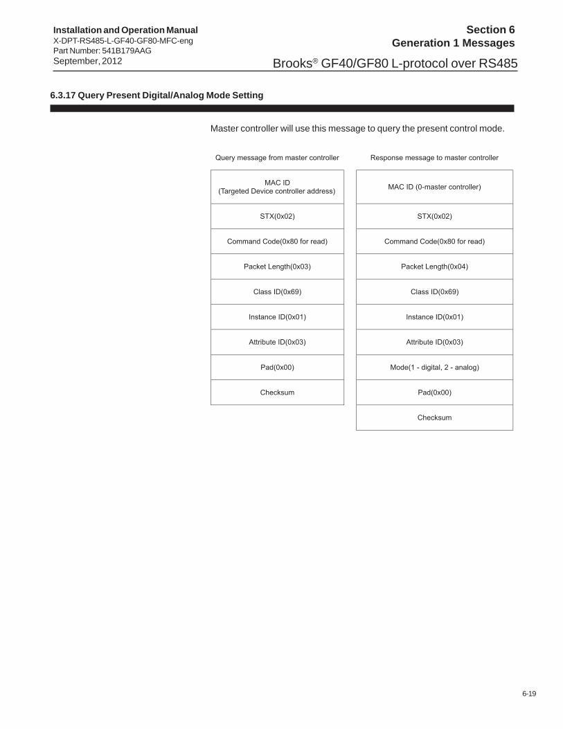
6.3.17 Query Present Digital/Analog Mode Setting
Master controller will use this message to query the present control mode.

6-20
Section 6Generation 1 Messages
Installation and Operation ManualX-DPT-RS485-L-GF40-GF80-MFC-eng
Part Number: 541B179AAGSeptember, 2012Brooks® GF40/GF80 L-protocol over RS485
6.3.18 Query for Default Control Mode
Master controller will use this message to query the default control mode.

6-21
Section 6Generation 1 Messages
Installation and Operation ManualX-DPT-RS485-L-GF40-GF80-MFC-engPart Number: 541B179AAGSeptember, 2012 Brooks® GF40/GF80 L-protocol over RS485
6.3.19 Set Fault Control Mode
Master controller will use this message to set an RS485 device controlmode when first powered up.

6-22
Section 6Generation 1 Messages
Installation and Operation ManualX-DPT-RS485-L-GF40-GF80-MFC-eng
Part Number: 541B179AAGSeptember, 2012Brooks® GF40/GF80 L-protocol over RS485
6.3.20 Set Freeze Follow
Master controller will use this message to configure an RS485 controller toact upon a new setpoint when recieved.

6-23
Section 6Generation 1 Messages
Installation and Operation ManualX-DPT-RS485-L-GF40-GF80-MFC-engPart Number: 541B179AAGSeptember, 2012 Brooks® GF40/GF80 L-protocol over RS485
6.3.21 Set New Setpoint
Master controller will use this message to send a new setpoint to an RS485device controller.
The flow calculation method is as defined in "6.2 RS485 Device NewSetpoint Conversion".

6-24
Section 6Generation 1 Messages
Installation and Operation ManualX-DPT-RS485-L-GF40-GF80-MFC-eng
Part Number: 541B179AAGSeptember, 2012Brooks® GF40/GF80 L-protocol over RS485
6.3.22 Set Ramp Time
Master controller will use this message to send a a ramp time to a MFCcontroller. The ramp time is how long the MFC controlller should take toreach the final setpoint for the current setpoint. The unit is millisecond. Azero ramp time effectively disables the ramping.

6-25
Section 6Generation 1 Messages
Installation and Operation ManualX-DPT-RS485-L-GF40-GF80-MFC-engPart Number: 541B179AAGSeptember, 2012 Brooks® GF40/GF80 L-protocol over RS485
6.3.23 Query Filtered Setpoint
Master controller will use this message to get the current setpoint from anRS485 controller. This is the current setpoint after ramping has beenapplied.

6-26
Section 6Generation 1 Messages
Installation and Operation ManualX-DPT-RS485-L-GF40-GF80-MFC-eng
Part Number: 541B179AAGSeptember, 2012Brooks® GF40/GF80 L-protocol over RS485
6.3.24 Query Indicated Flow/Pressure
Master controller will use this message to get the current flow reading froman RS485 device controller.
The flow calculation method is as defined in "6.2 RS485 Device NewSetpoint Conversion".

6-27
Section 6Generation 1 Messages
Installation and Operation ManualX-DPT-RS485-L-GF40-GF80-MFC-engPart Number: 541B179AAGSeptember, 2012 Brooks® GF40/GF80 L-protocol over RS485
6.3.25 Query Valve Drive Current
Master controller will use this message to get the valve drive current.

6-28
Section 6Generation 1 Messages
Installation and Operation ManualX-DPT-RS485-L-GF40-GF80-MFC-eng
Part Number: 541B179AAGSeptember, 2012Brooks® GF40/GF80 L-protocol over RS485
THIS PAGE WASINTENTIONALLY
LEFT BLANK

7-1
Section 7Generation 2 Messages
Installation and Operation ManualX-DPT-RS485-L-GF40-GF80-MFC-engPart Number: 541B179AAGSeptember, 2012 Brooks® GF40/GF80 L-protocol over RS485
7 Generation 2 Messages
7.1 Overview
GENERATION 2: Must support all of Generation 1 commands as defined– plus the following:
1 Commands will not be created with the following Class ID values: A0, A1,and A2. These will be considered Restricted Class ID values, for use byMFC suppliers should such suppliers require them for internal purposes2 These commands are supplier specific. All MFCs to whom thesecommands do not apply should return a reply of NSP.

7-2
Section 7Generation 2 Messages
Installation and Operation ManualX-DPT-RS485-L-GF40-GF80-MFC-eng
Part Number: 541B179AAGSeptember, 2012Brooks® GF40/GF80 L-protocol over RS485
7.2 Messages
7.2.1 Query Who Are You Manufacturer ID
Master controller will use this message to retrieve the RS485 deviceManufacturer ID.

7-3
Section 7Generation 2 Messages
Installation and Operation ManualX-DPT-RS485-L-GF40-GF80-MFC-engPart Number: 541B179AAGSeptember, 2012 Brooks® GF40/GF80 L-protocol over RS485
7.2.2 Query Who Are You Firmware
Master controller will use this message to retrieve the MFC firmware versioninformation.
In the response to the above command, RS485 device controller will returnthe firmware versiion of the RS485 device. Packet length will define thenumber of characters actually returned.

7-4
Section 7Generation 2 Messages
Installation and Operation ManualX-DPT-RS485-L-GF40-GF80-MFC-eng
Part Number: 541B179AAGSeptember, 2012Brooks® GF40/GF80 L-protocol over RS485
7.2.3 Query Who Are You Device Details
Master controller will use this message to retrieve the RS485 devicecontroller specific capability information.

7-5
Section 7Generation 2 Messages
Installation and Operation ManualX-DPT-RS485-L-GF40-GF80-MFC-engPart Number: 541B179AAGSeptember, 2012 Brooks® GF40/GF80 L-protocol over RS485
In response to the above command, Digital MFC Controller will returninformation regarding the MFC capabilities. Request is for several pieces ofinformation in a specific order:1. MFC Full Scale size in tenths of a SCCM 4 byte unsigned integer format,• To report MFC size in 10th of sccm as an integer. Take MFC size, multipleby 10, and convert to integer format.• In tenths of a sccm – a 100 sccm device would be returned as 100*10 toconvert this to 10th of sccm in integer format.• If the MFC size were 100.5 sccm, the number they would return would be1005.• If the MFC size were 100.55 sccm, the number reported would be 1005(or 1006 if you round up in your math routine).
2. SEMI Gas ID number for currently selected gas instance in 4 byteunsigned integer,3. SEMI Gas ID number for Calibration gas used in 4 byte unsignedinteger, and4. GENERIC calibration information and may be used for SEMI Gas IDnumber for Secondary calibration gas used or algorithm identity or othermanufacturer information useful in identifying calibration information.
Field is 4 byte unsigned integer – return zeros if not applicable.
7-6
Section 7Generation 2 Messages
Installation and Operation ManualX-DPT-RS485-L-GF40-GF80-MFC-eng
Part Number: 541B179AAGSeptember, 2012Brooks® GF40/GF80 L-protocol over RS485
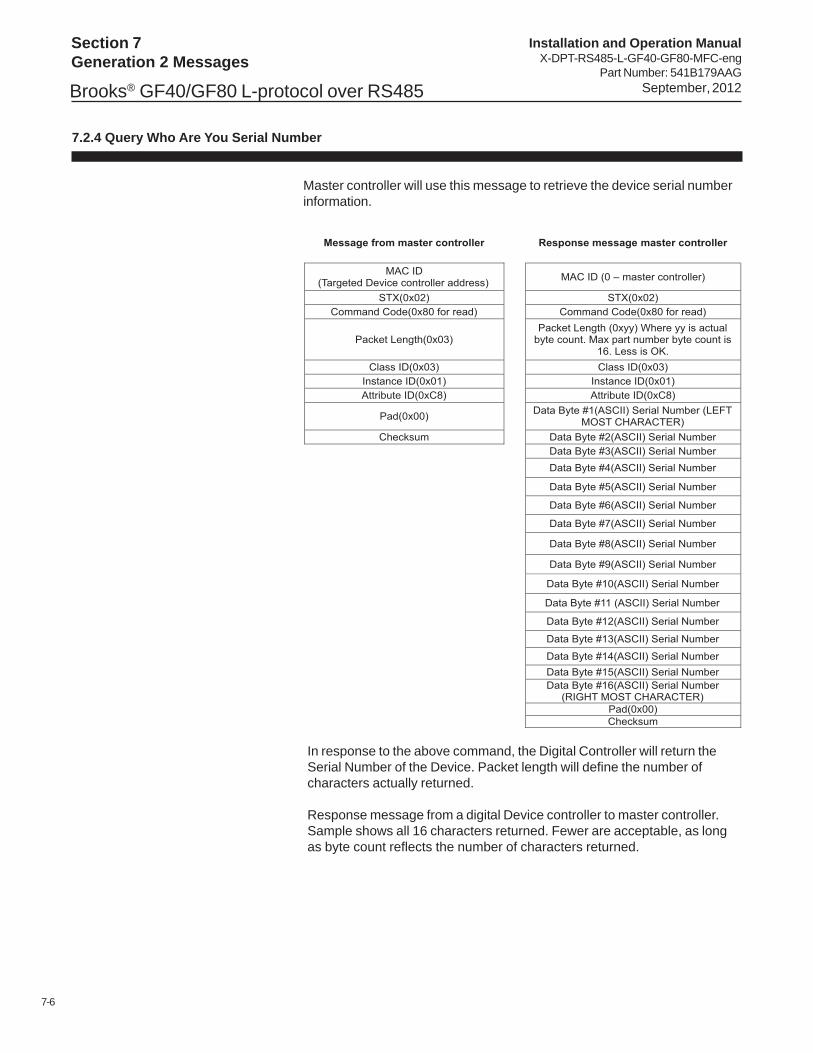
7.2.4 Query Who Are You Serial Number
Master controller will use this message to retrieve the device serial numberinformation.
In response to the above command, the Digital Controller will return theSerial Number of the Device. Packet length will define the number ofcharacters actually returned.
Response message from a digital Device controller to master controller.Sample shows all 16 characters returned. Fewer are acceptable, as longas byte count reflects the number of characters returned.

7-7
Section 7Generation 2 Messages
Installation and Operation ManualX-DPT-RS485-L-GF40-GF80-MFC-engPart Number: 541B179AAGSeptember, 2012 Brooks® GF40/GF80 L-protocol over RS485
7.2.5 Set Freeze Follow Broadcast
Single Freeze Follow Broadcast Message form Master Controller.

7-8
Section 7Generation 2 Messages
Installation and Operation ManualX-DPT-RS485-L-GF40-GF80-MFC-eng
Part Number: 541B179AAGSeptember, 2012Brooks® GF40/GF80 L-protocol over RS485
7.2.6 Set New Setpoint Long
New Setpoint Long includes Ramp and Freeze Follow.
Master controller will use this long message to prepare for the next set point.This message will use a single data exchange to pass the Freeze FollowFlag, Ramp time to ‘Next’ set point and the ‘Next’ set point to the device. Itwill expect to receive the same response as it would have received from thestandard New Set Point command – an ACK.
If Freeze Follow is set to 1 – use the ‘Next’ set point and its RAMP indicatorimmediately. If Freeze follow is set to 0 wait for a broadcast ‘immediate’command (See previous Item). NOTE: May be overridden/cancelled byanother ‘set point’ command. Status read commands received will behonored and will not change the settings for this new set point command.
If Ramp is set to zero, no ramp is required. If value is non-zero – alwaysramp. If a value is provided, this value is in milliseconds and is to be thetime used for a linear ramp to next set point. RS485 device is to always setthe last value for the set point to the actual set point requested at the end ofthe ramp. Once it reaches the set point it should stop. It is desired to avoidovershoot. If the time provided exceeds the RS485 device capability – set itto the RS485 device capability.

7-9
Section 7Generation 2 Messages
Installation and Operation ManualX-DPT-RS485-L-GF40-GF80-MFC-engPart Number: 541B179AAGSeptember, 2012 Brooks® GF40/GF80 L-protocol over RS485
This message is intended to be used as an alternate to the now utilized NewSet Point, Ramp time, and Original Freeze Follow individual commands andsimply combines all of the commands into a single message. It is intendedto be issued at the same frequency as the older set commands – potentiallyevery 250 – 500 ms.
All set point values will be percent of full scale and are passed as fractionalvalues in the same format as historically used, with 0x4000 correspondingto 0% of the parameter, and 0xC000 corresponding to 100% of theparameter.

7-10
Section 7Generation 2 Messages
Installation and Operation ManualX-DPT-RS485-L-GF40-GF80-MFC-eng
Part Number: 541B179AAGSeptember, 2012Brooks® GF40/GF80 L-protocol over RS485
7.2.7 Query Indicated Flow Long
This request will be used to obtain the current flow reading as well as otherRS485 device operating status information.
1. Current indicated flow in % of full scale (2 bytes)0x3333 to 0x4000 = -10% to 0%0x4000 to 0xC000 = 0% to 100%0xC000 to 0xE000 = 100% to 125%
2. Reading from the upstream pressure transducer hundredths psi units (2byte signed integer)0x0000 to 0x7FFF = 0.00psi to 327.67psi0x8000 to 0xFFFF = -327.68psi to -0.01psi
3. Valve voltage or Valve current as appropriate for the RS485 devicehundredths of a % full scale (2 byte signed integer)0x0000 to 0x7FFF = 0.00% to 100.00%0x8000 to 0xFFFF = -100.00% to -0.01%4. RS485 device internal temperature sensor reading hundredths of degreeC (2 byte signed integer)0x0000 to 0x7FFF = 0.00degC to 327.67degC0x8000 to 0xFFFF = -327.68degC to -0.01degC

7-11
Section 7Generation 2 Messages
Installation and Operation ManualX-DPT-RS485-L-GF40-GF80-MFC-engPart Number: 541B179AAGSeptember, 2012 Brooks® GF40/GF80 L-protocol over RS485
7.2.8 Query Command Retrieval
Master controller will use the following command to retrieve what commandsthe Digital RS485 device Controller believes it has been given.
Digital RS485 device Controller will return the following message in theorder specified:1) Current Freeze Follow Flag (1 byte)2) Current Target Set point in % of Full Scale (not actual flow, not indicatedflow, not valve position) (2 bytes 4000 to C000 as is standard)3) Next Set point (2 bytes 4000 to C000 as is standard)4) Ramp time for ‘Next Set point’ (2 bytes in milliseconds)

7-12
Section 7Generation 2 Messages
Installation and Operation ManualX-DPT-RS485-L-GF40-GF80-MFC-eng
Part Number: 541B179AAGSeptember, 2012Brooks® GF40/GF80 L-protocol over RS485
THIS PAGE WASINTENTIONALLY
LEFT BLANK

Installation and Operation ManualX-DPT-RS485-L-GF40-GF80-MFC-engPart Number: 541B179AAGSeptember, 2012 Brooks® GF40/GF80 L-protocol over RS485

Installation and Operation ManualX-DPT-RS485-L-GF40-GF80-MFC-eng
Part Number: 541B179AAGSeptember, 2012Brooks® GF40/GF80 L-protocol over RS485
TRADEMARKSBrooks .......................................................................Brooks Instrument, LLC
LIMITED WARRANTYSeller warrants that the Goods manufactured by Seller will be free from defects in materials or workmanship under normaluse and service and that the Software will execute the programming instructions provided by Seller until the expiration of theearlier of twelve (12) months from the date of initial installation or eighteen (18) months from the date of shipment by Seller.Products purchased by Seller from a third party for resale to Buyer (“Resale Products”) shall carry only the warrantyextended by the original manufacturer.All replacements or repairs necessitated by inadequate preventive maintenance, or by normal wear and usage, or by fault ofBuyer, or by unsuitable power sources or by attack or deterioration under unsuitable environmental conditions, or by abuse,accident, alteration, misuse, improper installation, modification, repair, storage or handling, or any other cause not the faultof Seller are not covered by this limited warranty, and shall be at Buyer’s expense.Goods repaired and parts replaced during the warranty period shall be in warranty for the remainder of the original warrantyperiod or ninety (90) days, whichever is longer. This limited warranty is the only warranty made by Seller and can beamended only in a writing signed by an authorized representative of Seller.
BROOKS SERVICE AND SUPPORTBrooks is committed to assuring all of our customers receive the ideal flow solution for their application, along withoutstanding service and support to back it up. We operate first class repair facilities located around the world to providerapid response and support. Each location utilizes primary standard calibration equipment to ensure accuracy andreliability for repairs and recalibration and is certified by our local Weights and Measures Authorities and traceable to therelevant International Standards.
Visit www.BrooksInstrument.com to locate the service location nearest to you.
START-UP SERVICE AND IN-SITU CALIBRATIONBrooks Instrument can provide start-up service prior to operation when required.For some process applications, where ISO-9001 Quality Certification is important, it is mandatory to verify and/or (re)calibratethe products periodically. In many cases this service can be provided under in-situ conditions, and the results will be traceableto the relevant international quality standards.
CUSTOMER SEMINARS AND TRAININGBrooks Instrument can provide customer seminars and dedicated training to engineers, end users and maintenance persons.
Please contact your nearest sales representative for more details.
HELP DESKIn case you need technical assistance:
USA 888 275 8946 Korea +82 31 708 2521Netherlands +31 (0) 318 549 290 Taiwan +886 3 5590 988Germany +49 351 215 2040 China +86 21 5079 8828Japan +81 3 5633 7100 Singapore +6297 9741
Due to Brooks Instrument's commitment to continuous improvement of our products, all specifications are subject to changewithout notice.